1C:Enterprise 8.3 Administrator guide. Client/server mode.
Contents
Introduction
Overview
Chapter 1 contains system requirements for 1C:Enterprise server deployment and operation.
Chapter 2 describes client/server mode features.
Chapter 3 provides information on 1C:Enterprise server deployment.
Chapter 4 describes 1C:Enterprise server startup.
Chapter 5 provides information on administration features in 1C:Enterprise client/server mode.
Chapter 6 outlines required actions to update the server cluster.
Chapter 7 provides information on how to remove 1C:Enterprise.
Agreed Notations
Keys. Keys such as Enter, Esc, Del, and others are given without quotation marks.
The Arrow keys phrase is used to specify all arrow keys at once. They are individually referred to as Up Arrow, Down Arrow, Right Arrow, and Left Arrow.
Keyboard shortcuts. When a command requires a keyboard shortcut, it will be denoted as Ctrl + F3. All keyboard shortcuts in the guide are specified for PC-compatible computers. On Apple computers, you need to use Cmd instead of Ctrl and Option instead of Alt in the given keyboard shortcuts. So, the keyboard shortcut Ctrl + Alt + Shift + F5 for a PC-compatible computer will look as follows for an Apple computer: Cmd + Option + Shift + F5.
Buttons. Form buttons are given without quotation marks, like OK, Cancel, Delete, and others.
1C:Enterprise language keywords. 1C:Enterprise language keywords are highlighted by specific font and are given as in modules, for example: WorkingDate. This manual contains references to some parts of 1C:Enterprise language description (sections, methods, attributes, and others). For these descriptions, see the application help (the 1C:Enterprise language section).
Menu actions. Menu interactions are described as follows: Menu – Submenu – Submenu – ... – Menu item. For example: "To select the picture scale, click Table – View – Scale" is similar to: "To select the picture scale, use the Scale menu item of the View submenu in the Table menu in the main menu of the application". If any menu, other than the main menu, is referred, it is specified explicitly.
1C:Enterprise modes. Configuration setup and validation (hereinafter referred to as Designer mode), and configuration execution (hereinafter referred to as 1C:Enterprise mode).
In this manual, the "user" refers to a specialist who develops or maintains the configuration.
The following abbreviations and expressions may be used in this document:
| Expression | Description |
|---|---|
| %ALLUSERSPROFILE% | The %ALLUSERSPROFILE% expression means a Windows
environment variable with a directory available to all users. If the
operating system is installed using default settings, this path looks as
follows:
|
| %APPDATA% | The %APPDATA% expression means a Windows environment
variable that contains a path to the directory (in the user profile)
where application data is stored. If the operating system is installed
using default settings and the username is Smith, this
path looks as follows:
|
| %LOCALAPPDATA% | The %LOCALAPPDATA% expression means an environment
variable of Windows that contains a path to the directory (in the user
profile) where user-specific application data is stored. If the
operating system is installed using default settings and the username is
Smith, this path looks as follows:
|
| %PROGRAMFILES% | The %PROGRAMFILES% expression means a Windows
environment variable with a path to the directory that contains data
files for applications whose bitness matches the operating system
bitness. If the operating system was installed using default settings,
this expression equals to
|
| %PROGRAMFILES(x86)% | The %PROGRAMFILES(x86)% expression means a Windows
environment variable with a path to the directory that contains data
files for applications whose bitness does not match the
operating system bitness. In other words, this environment variable
contains a link to the directory where x32 applications are stored in
the x64 operating system. If the operating system was installed using
default settings, this expression equals to
|
| %SYSTEMROOT% | The %SYSTEMROOT% expression means a Windows
environment variable that contains a path to the operating system
installation directory. If the operating system was installed using
default settings, this expression equals to
|
| %USERPROFILE% | The %USERPROFILE% expression means a Windows
environment variable that contains a path to the current user profile
directory. If the operating system is installed using default settings
and the username is Smith, this path looks as
follows:
|
| ~/ $HOME | The $HOME expression or ~/ means a Linux or macOS environment variable with a path to the home directory of the user on whose behalf the current operating system session is running. The specific location of the user directory depends on the operating system used. The ~/.1cv8 expression means the .1cv8 directory located in the home directory of the current user. |
| A.B.C.D | For the 1C:Enterprise version, the A.B.C.D expression means that the full version number of the 8.3.24.123 format is to be used. |
| arch | The description of paths to the components of the installed
1C:Enterprise version (on Linux) can use the arch
expression. This expression, unless explicitly stated otherwise,
describes the processor architecture of the used version, which can take
the following values:
|
All files that have the same name in Windows and Linux will also have the same name in this manual. For example, the 1cestart.cfg file in this guide will be named 1CEStart.cfg on Windows, but 1cestart.cfg on Linux.
Extensions of executable files are not specified (if any). This means that 1cv8.exe is referred to as 1cv8 in this manual. On Windows, add the .exe extension. On Linux, do not add anything.
Also, Linux is case-sensitive, and Windows is not.
Chapter 1. System and Hardware Requirements
The list of currently supported server operating systems and DBMS is available at: https://1c-dn.com/library/system_requirements/.
1.1. Server x32
Minimal requirements for production servers included in a 32-bit 1C:Enterprise server cluster:
| Parameter | Value |
|---|---|
| Processor | Intel Pentium/Xeon 2400 MHz or higher. Multiple cores or processors are recommended because they affect the 1C:Enterprise 8 server cluster throughput especially having many concurrent users. |
| RAM | 4 GB or more |
| Storage | Hard drive or solid state drive. Installation requires at least 1 GB. The requirements do not include the database size. |
| Ports | USB port (for a dongle) |
| Linux | x86 processors:
|
| macOS | x86 processors:
|
| Windows | x86 processors:
|
1C:Enterprise supports several database management systems (DBMS). DBMS support depends on the computer's processor architecture. In the table below, the plus sign (+) indicates that a DBMS is supported on a computer with a processor architecture specified in the column header:
| DBMS \ Processor architecture | x86 | ARM64 | E2K |
|---|---|---|---|
| IBM Db2 | + | ||
| Microsoft SQL Server | + | ||
| Oracle Database | + | ||
| Pangolin | |||
| PostgreSQL | + | ||
| Tantor SE 1C |
For a full list of supported DBMS versions, see Supported DBMS. When installing on a 32-bit version of the operating system, use the 32-bit versions of the supported DBMS (if any).
Make sure that a computer running a DBMS server is in compliance with requirements applicable to any relevant DBMS version described in more detail in DBMS documentation. The bitness of DBMS server can differ from that of 1C:Enterprise server.
1.2. Server x64
1.2.1. Requirements to Servers Designed for Server Cluster Operation
Minimal requirements for production servers included in a 64-bit 1C:Enterprise server cluster:
| Parameter | Value |
|---|---|
| Processor |
|
| RAM | Minimum: 4 GB or more Recommended: 8 GB or more |
| Storage | Hard drive or solid state drive. Installation requires at least 1 GB. The requirements do not include the database size. |
| Ports | USB port (for a dongle) |
| Linux | x86/x86-64 processors:
|
| macOS | x86_64 processors:
|
| Windows | x86_64 processors:
|
1C:Enterprise supports several database management systems (DBMS). DBMS support depends on the computer's processor architecture. In the table below, the plus sign (+) indicates that a DBMS is supported on a computer with a processor architecture specified in the column header:
| DBMS \ Processor architecture | x86-64 | ARM64 | E2K |
|---|---|---|---|
| IBM Db2 | + | ||
| Microsoft SQL Server | + | ||
| Oracle Database | + | + | |
| Pangolin | + | ||
| PostgreSQL | + | + | + |
| Tantor SE 1C | + | + |
For a summarized list of supported DBMS versions, see Supported DBMS. When installing on a 64-bit version of the operating system, use the 64-bit versions of the supported DBMS (if any).
Make sure that a computer running a DBMS server is in compliance with requirements applicable to any relevant DBMS version described in more detail in DBMS documentation. The bitness of DBMS server can differ from that of 1C:Enterprise server.
1.2.2. Requirements for Data Accelerator Operation
The computer used for Data accelerator service operation must meet specific requirements:
-
CPU: Intel Nehalem or AMD Piledriver or later. Use a dual-core or a multi-core processor. The core means a physical core of a computer processor, including cores obtained through Hyper-Threading Technology, or any core of the virtual machine where Data Accelerator is running. When you start Data Accelerator on operating system under Hyper-V, select the Transfer to computer with another processor version check box in the virtual machine settings.
-
64-bit operating system:
-
Microsoft Windows: versions 7, 8, 8.1, 10, 11 (with all installed updates).
-
Microsoft Windows Server: 2012, 2012 R2, 2016, 2019, 2022.
-
Linux: corresponds to 1C:Enterprise system requirements (only OS version for supported architectures).
-
-
RAM:
-
Minimum memory: 64 GB.
-
Recommended memory: 512 GB.
-
On Linux, the /sys/kernel/mm/transparent_hugepage parameter of the operating system core must be set to madvise or never. At startup, Data Accelerator checks the parameter value.
1.3. General Requirements for Client/Server Mode
1.3.1. General Requirements
The network connection throughput might be significantly affected if 1C:Enterprise server cluster and the database server are installed on different computers. Network cards with throughput of at least 1Gbit are recommended to implement the following connections:
-
Server cluster and computer running DBMS of the main database.
-
Server cluster and computer running DBMS of a database copy whenever the database copying feature is used.
-
Server cluster computer running Data Accelerator and other computers being part of a server cluster whenever Data Accelerator is used.
The client application will not run on a virtual machine if the network adapter connection is set to NAT and 1C:Enterprise server cluster is located on a host computer for the virtual machine of the client application.
To use some 1C:Enterprise features, you might need to install Java 1.8 or later on computers with the server cluster. The bitness of Java must match the bitness of 1C:Enterprise server cluster. We recommend that you use the Liberica distribution. Features that require Java to be installed:
-
The ring utility and related utilities, for example, the licensing utility (ring license).
-
Optimized infobase restructuring (for DBMS Microsoft SQL Server or PostgreSQL).
-
Full-text data search, version 2.
Java may require additional setup for the correct system operation.
1.3.2. User Rights
User running server cluster processes (USR1CV8 by default) must have the following access rights:
-
General requirements:
- The user must have full rights to the cluster data directory. If cluster working processes are running on behalf of an individual user (using the swpuser.ini file), then it is recommended that such user has no access to the cluster data directory.
-
Windows:
-
List folder contents right to a directory with temporary files.
-
Log on as a service right.
-
Log on as a batch job right.
-
The user must be included in the Performance Log Users group.
-
-
Linux:
- Read right to the temporary files directory.
To increase cluster security, we recommend that you specify such settings in the swpuser.ini file so that working processes (rphost) are started on behalf of a user who does not have access to the directory specified as the cluster data directory.
1.3.3. Required Libraries on Linux
To use some features of a server running on Linux, you might require the following libraries:
-
FreeType:
-
Library name: libfreetype.
-
Version: 2.1.9 or later.
-
Purpose:
-
Operation of 1C:Enterprise server in managed mode.
-
Using the Chart, GraphicalSchema, or SpreadsheetDocument objects on the server.
-
Using the GetPicture() method of the Chart, GanttChart, Dendrogram, or PivotChart objects.
-
Saving to PDF.
-
-
-
Libgsf;
-
Library name: libgsf-1.
-
Version: 1.10.1 or later.
-
Purpose: export/import of XLS documents.
-
-
Glib;
-
Library name: libglib-2.0.
-
Version: 2.12.4 or later.
-
Purpose: export/import of XLS documents.
-
-
unixOdbc:
-
Library name: libodbc.
-
Version: 2.2.11 or later.
-
Purpose: operations with external data sources.
-
-
Kerberos:
-
Library name: libkrb5.
-
Version: 1.4.2 or later.
-
Purpose: OS authentication.
-
-
GSS-API Kerberos:
-
Library name: libgssapi_krb5.
-
Version: 1.4.2 or later.
-
Purpose: OS authentication.
-
-
Microsoft Core Fonts.
Libraries are imported by 1C:Enterprise as LibraryName.so.X.Y, where:
-
LibraryName is one of the values listed above.
-
so indicates a library file.
-
X.Y are library suffix digits.
Only libraries registered in runtime dynamic linker cache can be imported. To get this information, execute the ldconfig -p command. If several versions of the library are available, the latest one will be imported.
1.4. Power-Saving Modes
You can enable a power-saving mode with running 1C:Enterprise if:
-
Your security key is installed locally.
-
File mode is enabled.
-
Database file is located on the local drive.
Otherwise, power-saving modes are always unavailable.
1.5. Supported DBMS
1.5.1. General Information
1C:Enterprise supports several DBMS versions. This section contains the list of supported versions. Operating system to be used with a specific DBMS is defined by system requirements of the DBMS used.
For more information about supported DBMS (server bitness, used operating systems, numbers of supported versions), visit https://1c-dn.com/library/system_requirements/.
1.5.2. IBM Db2
You can download a supported IDM Db2 version at: https://releases.1c.ru/project/AddCompDB2 (requires IT-support section access).
Supported DBMS versions:
-
Version 9.1.
-
Version 9.5.
-
Version 9.7.
-
Version 10.1.
-
Version 11.1.
1.5.3. Microsoft SQL Server
If the Compatibility mode is greater than Version 8.3.7:
-
The minimal required Microsoft SQL Server DBMS version is Microsoft SQL Server 2005.
-
To use 1C:Enterprise, install the latest version of Microsoft OLE DB Driver for SQL Server or SQL Server Native Client for SQL Server 2005 (and later Microsoft SQL Server versions).
-
Presence of installed Microsoft OLE DB Driver for SQL Server or SQL Server Native Client is checked upon:
-
Creating an infobase
-
Importing an infobase
-
Updating a database configuration
-
The version of SQL Server Native Client must not be earlier than the version of Microsoft SQL Server.
Supported DBMS versions:
-
Version 2000 Service Pack 1 (Service Pack 4 is recommended)
-
Version 2005 Service Pack 3
-
Version 2008 Service Pack 1
-
Version 2008 R2
-
Version 2012
-
Version 2014
-
Version 2016
-
Version 2017
-
Version 2019
-
Version 2022.
1.5.4. Oracle Database
You can find the list of required DBMS patches at http://v8.1c.ru/requirements/.
Install Oracle Instant Client to use 1C:Enterprise. Otherwise, a server cluster cannot connect to Oracle Database DBMS.
-
Oracle Instant Client version: 12.1.0.2.0.
-
Distribution package: https://www.oracle.com/database/technologies/instant-client/downloads.html. Make sure that a distribution package you download is supported by the OS installed on your computer where 1C:Enterprise server cluster is running.
-
During the installation, it is recommended that you follow all the installation instructions included in the Oracle Instant Client package.
Supported DBMS versions:
-
Version 10g R2
-
Version 11g R1
-
Version 11g R2
-
Version 12c R1
-
Version 12c R2
-
Version 18c
-
19c version
1.5.5. Pangolin
Supported DBMS versions:
- Version 5.3.2.
1.5.6. PostgreSQL
The DBMS PostgreSQL is supported in several options:
-
PostgreSQL delivered by 1C Company.
-
PostgreSQL delivered by Postgres Pro company.
-
Postgres Pro Standard.
-
Postgres Pro Enterprise.
You can download the DBMS PostgreSQL delivered by 1C Company at: https://releases.1c.ru/project/AddCompPostgre (access to the technical support section is required).
Supported DBMS versions:
-
Version 8.1.5
-
Version 8.2.4
-
Version 8.3.8
-
Version 8.4.3
-
Version 9.0.3
-
Version 9.1
-
Version 9.2
-
Version 9.3
-
Version 9.4
-
Version 9.6
-
Version 10
-
Version 11
-
Version 12
-
Version 13
-
Version 14
-
Version 15
-
Version 16
-
Version 17.
1.5.7. Tantor SE 1C
Supported DBMS versions:
-
Version 14.8
-
Version 14.13.
-
Version 15.4
-
Version 15.6
-
Version 15.8.
-
Version 16.4
Chapter 2. Client/Server Mode
2.1. Overview
1C:Enterprise supports infobase operations in client/server mode. 1C:Enterprise client/server architecture consists of the following software layers:
-
1C:Enterprise client application (ordinary client, thin client, or web client)
-
Web server (only for web client and thin client connected over web server)
-
1C:Enterprise server cluster
-
Database server
In fig. 1, you can see the interaction scheme of system components.
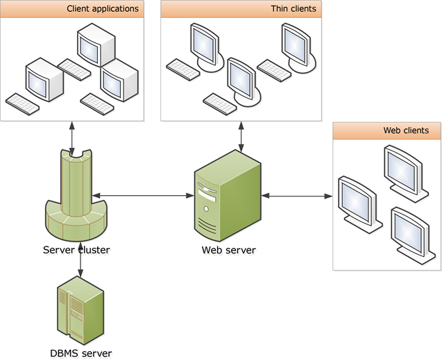
Fig. 1. Interaction scheme of system components
Client applications, thin clients and web clients are "1C:Enterprise" that end users use in various run modes. To run 1C:Enterprise web client, only a web browser is required.
1C:Enterprise server cluster is a logical entity comprised of working servers running on one or several computers, and a list of infobases stored in the cluster.
1C:Enterprise server cluster serves as a middle software layer between the client application and the database server. Client applications have no direct access to the database server. To access a database, client applications must interact with 1C:Enterprise server cluster.
The system architecture is intended to shift as much load as possible to the server cluster while keeping the essential functionality on the client side. All operations with applied objects, preparations before displaying the command interface and forms (reading item data from an infobase, filling form data, placing items, saving form data after change), and report generation are performed in the server cluster. The client only displays information prepared in the server cluster, interacts with the user, and calls server methods required for user operations.
Moreover, servers belonging to 1C:Enterprise server cluster also store files that contain event logs of infobases registered on a specific 1C:Enterprise server, as well as other service files. This data is not vital for routine infobase operations and its loss will not result in infobase failure. Background jobs run on the clustered servers as well.
To deploy 1C:Enterprise server cluster, use 1C:Enterprise installer. To configure the server cluster, use server cluster administration utility included in the distribution package.
1C:Enterprise server cluster dongle is not a network key, so you need to connect it to each computer running working processes of the cluster.
Web server is required to run web client and one of thin client variants. When web server is used, it serves as an intermediary in data exchange between server cluster and thin or web client.
Database server. Database server is used to store vital 1C:Enterprise infobase data in client/server mode. A variety of DBMS can serve as 1C:Enterprise database servers (see Supported DBMS). Each infobase is stored in a separate database of the selected DBMS.
2.2. Server Cluster Structure
2.2.1. General Concepts
Working server is the main unit of server cluster structure. Working server is a computer running a server agent (ragent). Server agent represents a working server in the server cluster. Generally, one computer hosts one working server. However, multiple working servers can run on a single computer if required (for example, for debugging purposes). Working servers running on the same computer must use different network ports and different cluster data directories.
Server cluster includes one or several working servers. However, information about how many working servers are running on a single physical computer is not important for the purpose of describing and running the cluster. A server agent maintains a server registry that specifies which production server serves as the main server for which cluster. A server registry is the 1cv8wsrv.lst file. The file contains the following information:
-
A list of server clusters that include this production server.
-
A list of administrators of this production server.
You can find the file in the server data directory. The server agent is not a part of the production server, but it supports the server operations and represents it in the server cluster.
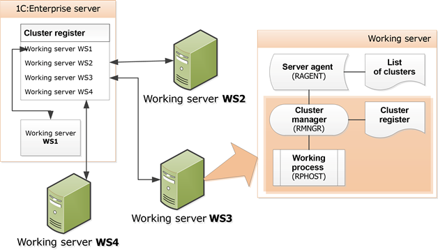 Fig. 2. Structure of 1C:Enterprise server
A cluster must contain at least one working server that has the Main server property set. The number of main servers per server cluster is unlimited. Therefore, you can select the Main server check box for all working servers in the cluster. A working server can be a main server in one cluster and a regular one in another cluster. Moreover, a working server with selected Main server check box can serve as a connection point for the server cluster it belongs to.
The working part of the working server includes the cluster manager (rmngr) and the working process (rphost). Cluster manager ensures normal operation of the working server and its interaction with other working servers within a cluster. Working process directly serves client applications, interacts with the database server, and executes the code marked in the application as "running on server side". The maximum number of working processes is determined by working server settings, server cluster settings, and hardware characteristics of the computer hosting the working server.
A working server must contain at least one cluster manager. A cluster manager running on the main server is called main cluster manager. The maximum number of cluster managers is equal to the number of cluster services. However, if a working server belongs to multiple clusters at the same time, at least one cluster manager per cluster will be created.
The main cluster manager maintains the cluster registry. A cluster registry is the 1cv8clst.lst file. The file contains the following information:
-
List of infobases registered in the cluster
-
List of working servers in the cluster
-
List of working processes in the cluster
-
List of cluster managers
-
List of cluster services
-
List of cluster administrators
You can find the cluster registry in the cluster data directory. The directory has a name of the reg_PORT kind and is located in the server data directory. PORT (in the name of the cluster data directory) is a cluster manager port (see Client application and server cluster interaction). If processes of multiple clusters are running on the production server, the server data directory will contain several cluster data directories, one for each cluster.
If a cluster contains multiple main servers, each main cluster manager maintains its cluster registry. To avoid data discrepancies, these cluster registry copies are constantly synchronized between the main cluster managers of main servers within a server cluster.
In the basic case, the working server and server cluster are hosted on the same computer (see fig. 4).
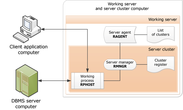 Fig. 3. Simple cluster
2.2.2. Client Application and Server Cluster Interaction
Interactions between 1C:Enterprise server cluster processes and the client application are performed over TCP/IP. Each cluster process is addressed using the name of a working server where it runs, and the network port number.
While configuring a server cluster, the following default network port numbers are used:
-
Server agent: port 1540;
-
Cluster manager: port 1541.
-
Port range for dynamic selection: 1560:1591. If required, network ports for working processes and additional cluster managers are allocated from this range. The allocation is performed according to the following rule:
-
Each working process occupies one network port.
-
Each additional cluster manager occupies one network port.
-
To create additional cluster managers, use the Manager for each service setting in the production server properties (see Adding production servers to a cluster).
You can change port numbers and range.
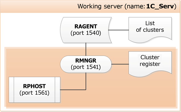
In the figure above, 1C_Serv is a main server. Therefore, it is addressed as 1C_Serv:1540. The cluster located on this server is addressed as 1C_Serv:1541, and the working process is addressed as 1C_Serv:1561.
Whenever the client application attempts to establish connection to an infobase in client/server mode, it uses the following server cluster address: 1C_Serv:1541.
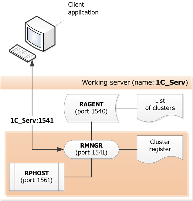 Fig. 5. Connecting to a simple cluster
The cluster manager assigns a working process that will serve the client application and sends its address to the client application. In this case, only one working process is available, therefore the 1C_Serv:1561 address will be used.
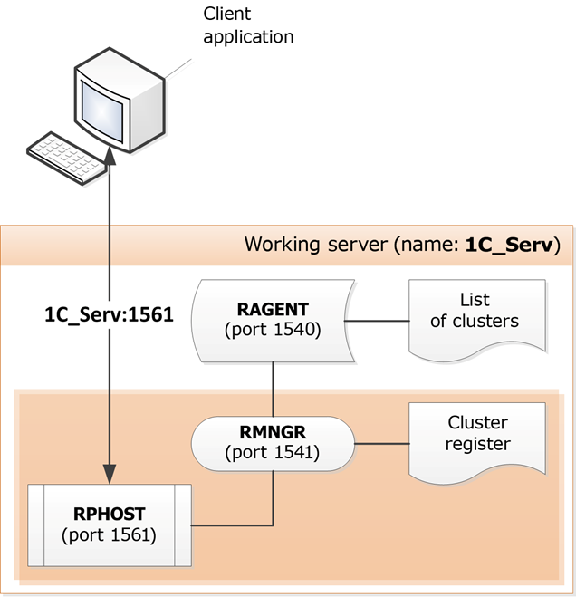 Fig. 6. Established connection
The client application establishes connection to the working process assigned to it. This process is responsible for infobase user authentication and any further interactions between the client application and the infobase.
2.2.3. Cluster Services
2.2.3.1. List of Services
All server cluster manager features are broken down into several independent services. Each service has specific characteristics. You can view the list of services, their brief description and characteristics below:
| Service | Description | Characteristics |
|---|---|---|
| Object locks | Stores pessimistic (not transaction-based) object locks. | Memory Replication Migration+ Instancing by infobases |
| External session management | Controls creation of sessions that require client licenses. | Migration+ Instancing by infobases |
| Time | Supports getting real-time timestamps and some auxiliary functions. | Replication Migration+ Instancing by infobases |
| Auxiliary cluster functions | Manages cluster lock information collection. | No migration |
| Data Accelerator | Allows creating data copies for high-speed preparation of analytical reports. Service works together with data base copies mechanism. | Memory Disk Migration- |
| Event logs | Supports access to event logs. | Disk Migration- Instancing by infobases Directory |
| Jobs | Starts and monitors lifetime of background and scheduled jobs. | Replication Migration+ |
| Integration data | Ensures operation of integration services. | Instancing by infobases No migration |
| Cluster configuration | Stores all cluster settings. | No migration Replication |
| Full-text search coordination service, version 2 | The service allows you to divide storage and maintenance of the search index between cluster managers. | Migration- Instancing by infobases |
| Licensing | Provides software license distribution. If the cluster licensing service that had issued licenses earlier is temporarily unavailable, this service issues duplicate licenses for no longer than 20 seconds. To ensure uninterrupted license acquisition from the licensing service, the rphost and rmngr processes of 1C:Enterprise server must have rights to create, read, and modify data in the 1cv8conn.pfl file. | Migration+ |
| Resource consumption counter monitoring | Calculates values of resource consumption indicators. | Disk Memory Migration- Directory |
| Numbers of database tables and fields | Provides unified numbering for database tables and fields. Used during database configuration updates that involve changes in database structure. | Migration+ Instancing by infobases |
| Numbering | Generates unique object numbers and codes. | Replication Migration+ Instancing by infobases |
| Database configuration updates | Performs background database restructuring. Before migrating this service between cluster managers, stop all working process. The system background job must be stopped as well. Therefore, the background update will be paused immediately after migration. | Replication Migration+ Instancing by infobases |
| Session reuse | Provides an automatic pool of reused sessions for Web services, HTTP services, and OData. | Migration+ |
| Full-text search | Performs full-text search and indexing. | Disk Migration- Instancing by infobases Directory |
| Full-text search, version 2 | The service is responsible for full-text search and indexing management: start on demand, start on a schedule, and information about the index status. | Disk Migration- Instancing by infobases Directory |
| Getting a list of sessions | Allows you to get a list of current sessions using various platform features, including internal cluster features, 1C:Enterprise language objects, and administration tools. | Migration+ |
| Custom settings | Provides access to files storing custom settings. | Migration- Instancing by infobases |
| OpenID provider | Stores OpenID authentication contexts. | Migration- Instancing by infobases |
| ODBC external data source management | Provides interaction with external databases over ODBC interface. | Memory Migration+ Instancing by infobases |
| External data source management using XMLA | Provides interaction with OLAP sources over XMLA interface. | Migration- Instancing by infobases |
| Speech recognition | Enables speech recognition. Receives (downloads) speech recognition models from an external model source (a recognition server). | Disk Memory Single server |
| Session data | Provides storage and caching of session information, for example, information in managed application forms. Provides client license acquisition. | Disk Replication Migration+ Instancing by infobases Directory |
| Cluster state | Contains dynamic data about cluster state and composition. | Replication No migration |
| Testing | Simulates user operations with 1C:Enterprise cluster. | Migration- |
| Transaction locks | Contains transaction locks for managed mode. | Memory Migration+ Instancing by infobases |
| Client notifications | Transfers client notifications from the server. | Replication Single server |
| Service for managing speech recognition models | Stores speech recognition models and distributes them among other production servers. | Disk Single server Directory |
| Debug item management | Manages debugger connection to server debug items. | No migration |
| Binary data storages | Maintains the operation of the binary data storage service. | Disk Migration- Directory |
Indicators used in the table:
-
Disk. Resource-intensive service that causes high load on the disk subsystem.
-
Memory. Resource-intensive service that causes high load on CPU and RAM.
-
Replication. Replication between the main and reserve service instances is supported. Replication is activated whenever the fault-tolerance level of the cluster is not zero (see Fault tolerance level). For cluster configuration services and cluster locks, the replication is activated when multiple production servers with the selected Main server checkbox are registered in the cluster.
-
Instancing by infobases. A separate service instance is used for each infobase.
-
Migration between production servers:
-
Migration+. Service migration between working servers is possible without any data loss.
-
Migration–. Service migration between working servers is possible with some data loss.
-
No migration. Service migration between working servers is impossible. Service can be located only on the computer hosting a main server of the cluster. Functionality assignment rules cannot be created for such services.
-
Single server. Service migration between production servers is unavailable. The service can be located on any single production server, not only on the main server.
-
-
Directory. Service can change the data storage directory.
Cluster services are evenly allocated between cluster production servers by service types, infobases, and sessions.
If at least one speech recognition model is registered in the server cluster, a special cluster manager that serves the speech recognition service starts running. The cluster manager will start despite the selected Manager for each cluster checkbox of the production server. The process of such cluster manager will have the rmstt name.
2.2.3.2. Changing the Location of Directories with Service Data
Some server cluster services allow you to change the location of the directory where the service data is stored. In the service list (see Cluster services), these services are marked as Directory. In this case, the cluster service data will be located in the specified directory, but the data storage structure will remain unchanged relative to the default storage locations. The following table contains a list of services that support data storage directory migration and the default data storage directory:
| Service | ID | Default path |
|---|---|---|
| Data Accelerator | DataAcceleratorService | <cdf>/1Сv8DbDA/<uuid-db> |
| Event logs | EventLogService | <cdf>/<uuid-db>/1Cv8Log |
| Resource consumption counter monitoring | CounterService | <cdf>/rescntsrv.lst |
| Full-text search | FulltextSearchService | <cdf>/<uuid-db>/1Cv8FTxt |
| Full-text search, version 2 | FullTextSearchServiceV2 | <cdf>/<uuid-db>/1Cv8FTxt2 |
| Session data | SessionDataService | <cdf>/snccntx/<uuid-rmngr> |
| Service for managing speech recognition models | SpeechToTextModelManagementService | <cdf>/STT |
| Binary data storages | BinaryDataStorageService | <cdf>/BinDataStrg/<uuid-db> |
This table has the following assumptions and notations:
-
All catalogs listed in the Default column are located in the cluster data directory.
-
<cdf>. Data directory of the server cluster. With the default location, this directory is equal to the directory specified in the /d command-line option for starting the server agent (ragent).
-
<uuid-db>. Infobase UUID in this server cluster.
-
<uuid-rmngr>. Cluster manager UUID.
After reassigning, the cluster data directory changes as follows: a part of the path that refers to the cluster directory (indicated in the table above as <cdf>) is replaced with the following path: <new directory>\reg_<port>, where <port> is a network port of the server agent.
If the service is divided by infobases, but no infobases are specified, a common directory is used for all server cluster databases, similar to how it is done in the default cluster settings. If the service can be divided by infobases, you can change both the common data catalog and the specific infobase catalog. In this case, the service data will be located as follows:
-
For infobases explicitly specified in the settings, "personal" directories will be used. The structure of data placement directories will remain unchanged.
-
All other infobases will be located in the common directory or the default directory.
If the data directory changes for event log services or binary data storage, it is required to transfer data of these services. Without this transfer, the server cluster may become completely inoperable. Remember that data transfer is performed by the administrator. The server cluster does not transfer data automatically.
For the rest of the cluster services, transferring the directory of a running service without transferring data may slow down the cluster and make some of the functionality temporarily inoperable. We do not recommend that you assign a network resource as the working directory of the cluster service, as this will lead to a significant decrease in the cluster performance. We also do not recommend that you assign the same directory to services from different server clusters. The administrator must monitor it manually.
To change the cluster data directory, use the service settings object. You can manage these objects both interactively (in the server cluster management console or the standard server management data processor) and using the object model of 1C:Enterprise language.
The general scheme for transferring the cluster service data directory is as follows:
-
The server cluster administrator creates service settings for the selected cluster services.
-
Connecting users and starting scheduled jobs is not allowed.
-
All background jobs are completed.
-
All users are disconnected.
-
The created settings are applied.
-
The server cluster is terminated.
-
The cluster services data is transferred to new directories.
-
A server cluster whose services will use the new data directories is started.
-
It becomes possible to connecting users and start scheduled jobs.
You need to restart the cluster (and terminate user sessions) as the changed cluster service directories are applied when the server cluster is started. So, even if you change in the event log storage directory of one infobase, it is necessary to restart the entire server cluster. We recommend that you carefully consider the location of new directories of cluster service data before creating new service settings and transferring data.
-
Speech recognition functionality.
-
Production server administration.
-
Service settings.
2.2.4. Sessions and Connections
2.2.4.1. General Information
Session defines the active infobase user and the processing thread assigned to the user. Any of these entities can become an active user:
-
1C:Enterprise client application instance
-
Web application instance running the web client
-
External connection instance (obtained from the V83.COMConnector object)
-
Background job instance
-
Web service call
Sessions can be active or hibernating. A hibernating session can maintain normal operation of the client application after the client computer is switched to different power-saving modes. A session hibernates when:
-
Session connection terminates abnormally (applicable for thick client, external connection, and thin client with direct server connection). If the network link is physically terminated, server requires 2–3 minutes to detect loss of connection to the client application;
-
Client application session times out due to inactivity (applicable for web client and thin client connected over web server). If power-saving mode is disabled on the client computer and no user operations are performed in the client application, it calls 1C:Enterprise server every 5-10 minutes to keep the session active. Therefore, it is not recommended that you set session hibernation time below 10 minutes.
Any activity of the client application wakes the session. A hibernating session is terminated when:
-
Hibernating session times out.
-
Locks set by the hibernating session conflict with the locks an active session attempts to set.
When an active session hibernates, its client license is revoked and becomes available. When a hibernating session wakes, it attempts to acquire a client license (provided that it has a client license prior to hibernation). If a license cannot be acquired, the session is terminated with a fatal exception.
Timeout values for inactive session hibernation and hibernating session termination are set in the infobase parameter settings in Designer.
All data stored in a cluster and related to an active user and becoming obsolete once the user session ends is referred to as session data. Session data includes:
-
Infobase
-
Session number
-
Authenticated infobase user
-
Interface language
-
Session parameter values
-
Temporary storages
-
Session statistics
-
Managed application form data
-
Internal data of the platform
Session data is saved by the cluster manager. Session data service is used for this purpose. Session data is retained when the service cluster restarts. If the active user makes no calls to the cluster during the timeout period and the session is not assigned to a connection, the session hibernates. The inactivity timeout period is set in the infobase parameter settings in Designer. The default value is 1200 seconds. To keep the session from hibernating, thin client and web client call the cluster every 10 minutes or less. For quicker access, session data is cached both in the working processes and thick clients. The list of active sessions is displayed in the list of active users.
Session data changes made during a server call are stored in the working process and passed to the cluster manager only when control is returned to the client (normally, or after a software exception).
Session data changes are not saved in the cluster manager if:
-
A working process was abnormally terminated during a server call.
-
A data transfer error has occurred when control was returned to the client.
Connection is used by sessions to access 1C:Enterprise server cluster, it contains a limited set of connection data and is not associated with the active user. Connections are also used in interactions between cluster processes.
To access the cluster from client, you need to assign the session to a connection. While the client does not attempt to access the cluster, no assignment is required.
Sessions and connections are used in different ways in different 1C:Enterprise modes.
-
Designer and thick client:
-
Upon startup: establishes connection, creates a session, and assigns the session to the connection.
-
Upon exit: cancels session assignment, closes the session and connection.
-
-
One web service call, and one execution of a background or scheduled job:
-
When the call starts: selects a connection from the pool, creates a session, and assigns the session to the connection.
-
When the call ends: cancels session assignment, terminates the session, returns the connection to the pool.
-
-
The thin client and web client start the session at startup and end the session at shutdown:
-
At the beginning of a cluster call, a connection from the pool is selected, and a session of this client is assigned to it.
-
At the end of the call, the session assignment to the connection is canceled and the connection is returned to the pool.
-
Session information can be viewed in:
-
Event log
-
Cluster console
-
Software administration tools
-
Technological log
-
Global context
Cluster administrator can retrieve a list of open sessions for a specific infobase or for the whole cluster, using the cluster administration utility or software administration tools.
Cluster administrator can end a session using the cluster administration utility or software administration tools. This will terminate the active user's session. Ending a session assigned to a connection will also close this connection.
Cluster administrator can set a session creation lock using the cluster administration utility or software administration tools. This prohibits creation of new sessions but does not affect any existing ones.
2.2.4.2. Connection Types
Connections are classified into two general types:
-
Infobase connections
-
Internal connections with working processes in the cluster
2.2.4.3. Infobase Connections
Infobase connections have several distinctive features:
-
Connection is established to a specific infobase in the cluster.
-
Code in 1C:Enterprise language can be executed in such connection.
-
Connection can be reestablished over time.
-
Connection can be terminated using a cluster console command or from 1C:Enterprise language.
-
Infobase connections in a working process of the cluster prevent the process from stopping or starting.
The following infobase connection types are available:
-
Thick client
-
Thin client
-
Designer
-
Web server extension module
-
COM connection
-
Background job,
-
System background job
Thick client
This connection is established between a thick client and an infobase. The connection is used to modify infobase data and perform other functions supported by infobase configuration.
The Thick client connection is established when a thick client is started interactively in 1C:Enterprise mode, or when Automation Client/Server technology is used to connect to an infobase, for example:
// Create 1C:Enterprise Automation server
AutomationServer= New COMObject("V83.Application");
// Establish infobase connection
// TestBase in cluster 1541 of the TestSrv main server
AutomationServer.Connect("Srvr="TestSrv";Ref="TestBase");
Thin client
This connection is established between a thin client and an infobase. The connection is used to modify infobase data and perform other functions supported by infobase configuration.
The Thin client connection is established when a thin client is started interactively, or when Automation Client/Server technology is used to connect to an infobase, for example:
// Create 1C:Enterprise Automation server
AutomationServer = New COMObject("V83C.Application");
// Establish infobase connection
// TestBase in cluster 1541 of the TestSrv main server
AutomationServer.Connect("Srvr="TestSrv";Ref="TestBase");
Designer
This connection is established between Designer and an infobase. The connection is used to create or modify infobase configurations, and perform administrative or scheduled activities.
Web server extension module
This connection is established between a web server and a working process of the server. You can use this connection for operation of: web clients, Internet services, thin clients over HTTP, and mobile clients.
The connection is established when an Internet service is called, or when a web client, thin client over HTTP, or mobile client calls 1C:Enterprise server. The connection exists until the web server is restarted or the connection is removed from the connection pool of web server extension modules (until its pool lifetime expires or until it is replaced by other connections).
-
Internet services.
-
Mobile client.
COM connection
This connection is established between a process using an external 1C:Enterprise connection and an infobase. The connection is used to modify infobase data and perform other functions supported by infobase configuration.
COM connection is established when COM technology is used to connect to an infobase, for example:
// Create 1C:Enterprise Automation server
COMConnector = New COMObject("V83.COMConnector");
// Establish infobase connection
// TestBase in cluster 1541 of the TestSrv main server
ConnectInfobase = COMConnector.Connect("Srvr="TestSrv";Ref="TestBase");
Background job
This connection is established between a working process of the cluster and an infobase. The connection is intended for executing the background job procedure code.
The background job connection is established in the following situations:
-
Receipt of a list of scheduled jobs registered in the infobase
-
Start of a scheduled job registered in the infobase
-
Background job start from 1C:Enterprise language
-
Report execution in the background
-
Background search by substring
-
Background list query execution
-
Start of background restructuring
Among others, developers can start background jobs using 1C:Enterprise language expressions. Example:
// Run the background job described in the procedure
// UpdateFullTextSearchIndex
// of the ScheduledProcedures common module
BackgroundJob = BackgroundJobs.Execute("ScheduledProcedures.UpdateFullTextSearchIndex");
The background job connection is maintained while the background job procedure context exists. Once the procedure is completed or the report is generated, the background job connection is closed.
System background job
This connection is established between a working process of the cluster and an infobase. This connection is intended for various operations that the system performs with the infobase during cluster operation. The following actions can be performed within this connection (the list is not exhaustive):
-
Background infobase configuration update. The background job connection is closed when background restructuring is completed.
-
Processing database copy notifications.
-
Processing notifications of the database copy feature.
-
Processing changes to administrative parameters and the security profile of the infobase.
-
Various service operations with the infobase:
-
Infobase context preload in the backup working process.
-
Recalculate totals.
-
Parallel dumping/restoring of the infobase.
-
Testing and debugging.
-
-
Background jobs.
-
Background report generation.
2.2.4.4. Service Connections
Service connections:
-
Access a working process rather than a specific infobase.
-
Do not run code in 1C:Enterprise language.
-
Cannot be terminated by a user.
-
Do not prevent working processes of a server cluster from stopping or starting.
The following service connection types are available:
-
Job scheduler
-
Debugger
-
Cluster console
-
Administration server
-
COM administrator.
Job scheduler
This connection is established between the job scheduler and a working process. You can use this connection to manage background jobs, which includes starting scheduled jobs at specified moments of time. This connection is also used in other situations when the cluster manager (rmngr) calls the working process (rphost), for example, when getting session lists.
The job scheduler connection is established during the first start of a background job. It can create a connection between a background job and an infobase within the same working process of a server cluster. After the background job connection is closed, the job scheduler connection stays active until the working process of the cluster is terminated or deleted.
Debugger
This connection is established between the debugger and a working process of a cluster in debug mode. You can use this connection to manage the debugging process and search for currently available debug items.
The debugger connection is established upon debug item attachment or search. The connection is closed upon debug item detachment or completion.
Cluster console
This connection is established between the server cluster console (mmc, see General information) and a working process. You can use this connection to administer server cluster infobases.
The cluster console connection is established when working process data is accessed (for example, when getting infobase parameters, a detailed list of infobase connections, and so on).
Administration server
This connection is established between the remote administration server of a server cluster and a working process. You can use this connection to administer server cluster infobases.
The remote administration connection is established when working process data is accessed (for example, when getting infobase parameters, a detailed list of infobase connections, and so on).
COM administrator
This connection is established with a working process of the server using COM technology. You can use this connection to administer server cluster infobases.
The COM administrator connection is established when a working process is accessed using COM technology, for example:
// Create 1C:Enterprise COMConnector
COMConnector = New COMObject("V83.COMConnector");
// Establish connection with working process 1562
// in cluster 1541 of the TestSrv main cluster
ConnectWorkingProcess = COMConnector.ConnectWorkingProcess("tcp://TestSrv:1562");
2.2.4.5. Session Types
The following session types are available:
-
COM administrator
-
COM connection
-
WS connection
-
Web client
-
Analytics system request
-
Analytics system client
-
Cluster console
-
Designer
-
Mobile client
-
Administration server
-
Thick client
-
Thin client
-
Background job
Descriptions of sessions are generally similar to the above descriptions of corresponding connections. Descriptions of other sessions are provided below.
Web client
This session is a web client instance presentation in a server cluster. You can use this session to modify infobase data and apply other features available in the infobase configuration. Web client calls the server over the Web server extension module connection.
The Web client session is created when web client is started in interactive mode. It is closed when the interactive infobase session is terminated (the last web browser window is closed).
Analytics system request
It is a presentation in the server cluster of the analytics system. You can use the session to execute analytics system queries to the 1C:Enterprise server cluster. Analytics system request calls the server over the Web server extension module connection.
The Analytics system request session starts when the analytics system requires some data from the 1C:Enterprise server cluster. Session pool parameters determine the session termination parameters.
Analytics system client
It is a presentation in the server cluster of the analytics system. With the session, the analytics system interacts with the 1C:Enterprise server cluster (excluding query execution). The analytics system client calls the server over the Web server extension module connection.
The Analytics system client session starts when the analytics system starts from the 1C:Enterprise client application. The session is terminated either when the user logs out of the system or automatically according to the parameters (similar to the web client).
Mobile client
This session is a mobile client instance presentation in a server cluster. You can use this session to modify infobase data and apply other features available in the infobase configuration. Web client calls the server over the Web server extension module connection.
The Mobile client session is created when mobile client is started on a mobile device. It is closed when the infobase session is terminated (the mobile application is closed on the mobile device).
2.2.5. Failover Cluster
A failover cluster ensures uninterrupted user experience in the following situations:
-
Working processes and cluster managers are restarted (both on schedule or abnormally).
-
A cluster server fails.
This section covers the mechanisms ensuring uninterrupted operation.
2.2.5.1. Transactional Nature of Session Data
Upon a failure, sessions are saved and can be restored after reconnection. However, the system ends a session instead and prompts to restart the client application in certain situations, such as:
-
A working process has failed during a server call after the first transaction of this call has been committed.
-
A data transfer error has occurred when control was returned to the client.
2.2.5.2. Last Call Retry
If a data transfer error occurs during a server call, it might mean that:
-
A communication channel was broken.
-
A working process of the server was abnormally terminated.
If the client application calls a server outside of transaction and the client receives a data transfer error before the first transaction within the server call is committed, the client automatically reconnects to the server and retries the call. Then, the client continues normal operation.
If the client receives a data transfer error after the first transaction within the server call is committed, the session of this client terminates and the client application must be restarted to proceed.
2.2.5.3. Interactive Action Retry
If the client application calls a server within transaction (in standard mode instead of managed application mode), the data transfer error is considered to be a recoverable error and results in failure of the interactive action, not the client application.
Please note that application data integrity is not ensured by the platform if the interactive action contains multiple transactions or modifies application data status (except for the data with caching logic supported).
2.2.5.4. Working Process Backup
If a working process is abnormally terminated, the server cluster starts another working process. Further, an attempt to move all client sessions serviced by the terminated working process to another working process is made. As a result, users might experience noticeable delays: the client application can cease to respond to user commands and it may appear to the user that the client application is hanging.
To mitigate manifestations of this problem, which arises when you try to move existing sessions to another working process, server cluster enables you to create special backup working processes. Working processes are backed up for each infobase individually. Infobases with working process backup function switched on are called 'redundant'. Administrator can specify infobases for which backup working processes have to be created.
As such, the operation logic is as follows.
-
Working servers storing redundant infobases run backup working processes.
-
The said working processes load metadata from redundant infobases.
-
Whenever necessary, client sessions switch to backup working processes with all proper data already loaded. The foregoing process is performed without delay.
-
As soon as a backup working process becomes a standard working process, it is no more deemed a redundant process, and server cluster creates further backup working processes to get the required number thereof by way of starting new backup working processes.
The number of backup working processes is determined by the Number of infobases per process working server property. If you need to back up a working process, select the Working process backup check box in the infobase properties (cluster console). If a working process is a backup process, select the Backup check box in its properties. It is cleared as soon as a working process becomes an active process.
-
Viewing infobase properties (see Viewing infobase properties).
-
Viewing working process properties (see Viewing the list of working processes).
-
Viewing working process properties (see Viewing and editing cluster server properties).
2.2.5.5. Fault Tolerance Level
Fault tolerance level defines the maximum number of working servers in the cluster whose concurrent failure would not result in abnormal termination of any user sessions. Keep in mind that "failure" implies situations such as: computer power-off, network cable break, operating system problems preventing the process from running, and so on.
Therefore, if a server cluster contains only one working server, its fault tolerance level is 0 since failure of the only server will result in abnormal termination of all user sessions. If a server cluster contains 4 working servers, its fault tolerance level may vary from 0 to 3. 0 means that failure of any working server results in cluster failure. 3 means that the cluster will remain in operation even if 3 out of 4 working servers fail.
Please note that any increase in fault tolerance level affects cluster performance, as some cluster resources are spent on synchronization of data between working servers.
Fault tolerance level depends on the number of main servers in the cluster. The number of main servers determines whether new connections can be created. If, for example, a cluster of 3 working servers contains 2 main servers one of which has been abnormally terminated, users will have access to infobases. In this case, two servers are still operable: one main server and one working server. If there is only one main server in the cluster, the server crash will make the cluster unavailable to users even if 2 more working servers remain operational.
If a cluster contains 1 main server and 2 working servers (3 in total) and the fault tolerance level is 1, this might lead to several scenarios. Let us have a closer look at them.
Failure of one working server
An ordinary working server is abnormally terminated. This is within the resilience level and the cluster keeps running user sessions. New users can be connected as the main server is functioning properly.
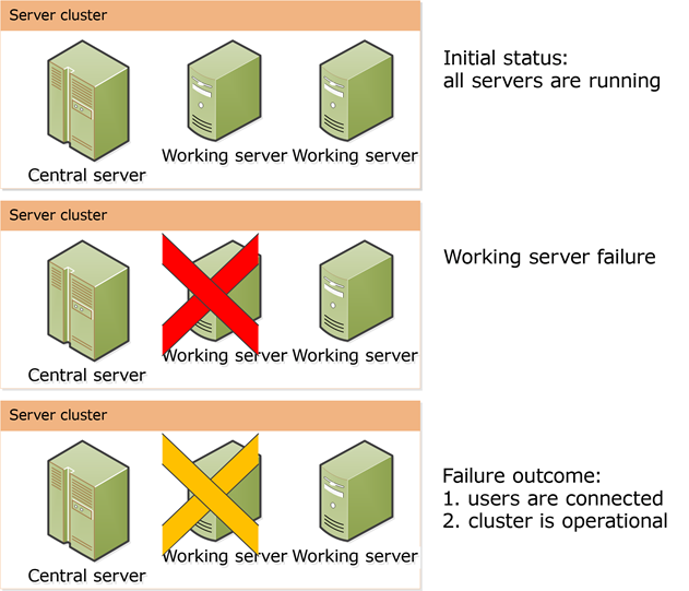 Fig. 7. Failure of one working server
Failure of the main server
The main server is abnormally terminated. This is within the fault tolerance level, but the cluster stops serving users as the only main server is down.
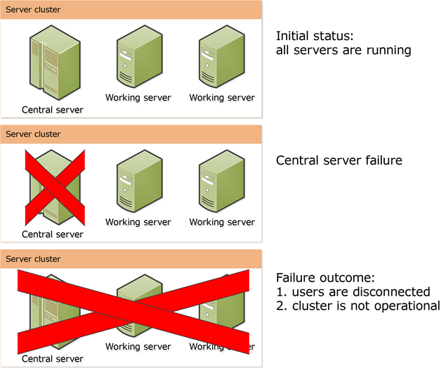 Fig. 8. Abnormal termination of the main server
Failure of two working servers
Two working servers are abnormally terminated while the main server keeps functioning. The fault tolerance level is exceeded and all user sessions served by the failed working servers will be closed. Users served by the main server will be able to continue their operations. You can also connect new users.
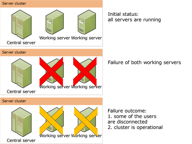 Fig. 9. Failure of two working servers
Therefore, the fault tolerance level in relation to the number of main servers in the cluster is calculated as follows: Number of main servers = Fault tolerance level + 1. Keep in mind that following this formula literally may decrease cluster performance as some system resources will be used to synchronize data between working servers. When you define the number of main servers and fault tolerance level, you need to find balance between the fault tolerance level and acceptable level of cluster performance considering hardware specifications of cluster computers.
2.2.5.6. Connection Break Monitoring
Load balancing and failover cluster systems use TCP connections (network connections) between cluster components. TCP connections are also used when the thin or thick client application connects directly (without using a web server) to 1C:Enterprise server. If the availability of cluster components is determined incorrectly, the mechanisms that rely on it will not function adequately or correctly. To determine the correct availability of cluster components, you can use a special system that monitors broken connections between cluster components.
This system monitors network connections between server cluster processes (both on the same computer and on different computers), between a server cluster and a web server extension, and between a client application and a server cluster to achieve the following goals:
-
Rapid detection of loss of connection between components.
-
Economical monitoring of the integrity of connections between cluster components.
For verification purposes, the concept of verification direction is used. Verification direction is a group of connections among server cluster components that are joined by the following rules:
-
Outgoing connections to the target address (computer name and port that uniquely identify a specific component of the server cluster).
-
Incoming connections from a web server extension by a UUID that uniquely identifies infobase publication on the web server.
-
Other incoming connections are identified by a UUID that uniquely identifies the source process.
For each direction, a small data package is periodically sent and response is expected. Verification is carried out at both connection sides. Verification parameters are passed from the connection source.
Packages are sent and expected over UDP and TCP. Initially, packages are sent via UDP and in case of no response within the entire direction lifetime, a TCP connection is established upon timeout and verification is attempted over the new connection. Such direction is still considered available. TCP verification mode is less accurate and can cause false positives when small timeouts are set. When you set up a server cluster and publish infobases on a web server, it is recommended that you ensure accessibility among all cluster computers as well as among cluster computers and web server computers over TCP and UDP (with the same port numbers). To control the tracking system, use the following parameters:
-
Verification period. Time period between sending test packages.
-
Verification timeout. Time period during which the message sender must receive at least one response package by the selected direction. The time period is measured starting from the previous response package receipt (or system startup).
If no packages are received from the other side within the verification timeout period, the verification direction is considered unavailable, except when switching from UDP to TCP. Once a verification direction is considered unavailable, all connections in that direction are marked as unusable and are terminated the first time they are accessed. At the same time, all available components of the server cluster are notified of the disconnection of a certain direction so that the cluster can respond quickly to the upcoming disconnection (including the removal of locks corresponding to the unavailable process).
The server cluster administrator can monitor the quality of connection between cluster components. For that to happen, connection verification statistics for the past 10 seconds are recorded in the technological log every 10 seconds. In particular, it displays information about the average response time and the maximum response time. This information allows you to set optimal verification timeout values that will not lead to false positives of the verification system, but, at the same time, will ensure reliable operation of the system. In the technological log, this information is recorded in the CONN event.
If any parameter of the system that monitors broken connections is set to 0, its operation algorithm changes. In this case, verification is performed only by the side that initiated the network connection and test packages are sent every 5 seconds. The process that receives test packages determines that the connection is broken if it does not receive any packages within 200 seconds. The source process will only know about the disconnection after the TCP connection timeout occurs, which is determined by the operating system settings. If the system that monitors broken connections is set up this way, the period of sending messages and timeout are not configured and connection statistics information is not displayed in the technological log. This setup option of the system that monitors broken connections (verification period or timeout period is set to 0) is not recommended.
When you monitor a connection break between a client application and a server cluster, check periods and timeouts are fixed and cannot be changed:
-
For thick client:
-
Check period: 12 seconds.
-
Check timeout: 60 seconds.
-
-
For thin client:
-
Check period: 3 seconds.
-
Check timeout: 15 seconds.
-
The default period and timeout to check connections between a web server extension and the server cluster are 3 and 15 seconds. You can change them using the parameters of infobase publication on the web server.
The default period and timeout to check connections between server cluster processes are 1 and 5 seconds. You can change them using the parameters of server agent startup (for details, see Running the server agent).
2.2.6. Server Cluster Scalability
Cluster server scalability can be achieved by:
-
Increasing the computing power of the computer where a single working server is deployed.
-
Adding one or several working servers to the server cluster.
The server cluster automatically executes all scalability activities. The cluster administrator can affect these activities by modifying the working server properties.
New servers can be added to the cluster list of working servers, and the properties of existing servers can be modified (see Operations with the list of working servers in a cluster). Modified properties do not take effect until a new session or connection is created. When removing a working server from the cluster, ensure that user sessions being run by this server will not be terminated. For more information on how to delete a production server, see Removing servers from a cluster. The last working server with selected Main server check box cannot be removed from the cluster. When a default cluster is created, the working server of the computer used to create the server cluster is automatically added to the list of working servers and the Main server check box is selected for it.
The server cluster automatically distributes the load between working servers to achieve the quickest possible response time for client applications. Cluster services are evenly distributed between working servers by service types, infobases, and sessions.
When establishing an infobase connection, the server cluster selects working servers with maximum performance available at the moment. Existing connections can be moved to other working servers. For more information, see Cluster load balancing.
For more information on other properties managing a production server, see Adding production servers to a cluster.
2.2.7. Cluster Load Balancing
2.2.7.1. Available Performance of a Working Process
Each working process has the Available performance property. It defines how quickly the working process can perform reference operations compared to other working processes. Reference operations include:
-
Memory operations: array allocation, population, and deallocation.
-
File operations: creation, saving, and deletion.
-
Assessment of processor load for the computer running the working process and defining the number of threads to run. This value increases execution time of the reference call.
On Windows, the user that runs a server must belong to the Performance Log Users group. Otherwise, processor load assessment is not performed.
Value of the Available performance property is calculated by dividing 10,000 by the average time (within 5 minutes) required by the current working process to perform reference operations. The speed with which reference operations are performed is measured every 5 seconds.
Clients are allocated among working processes so as to ensure a roughly equivalent available performance for each working process. The 25% difference in available performance levels is considered substantial.
When balance between the available performance of working processes changes, the clients are dynamically reallocated to working processes within 10 minutes.
When a working process is disabled, clients allocated to it are dynamically reallocated to the remaining active working processes.
2.2.7.2. Establishing a New Connection
2.2.7.3. Direct Server Connection
When establishing a new connection to 1C:Enterprise server, you can specify how the working process will be selected (the Load balancing mode server cluster property):
-
By performance
-
By available memory
- Selection by performance
- A list of suitable working servers with performance not less than 75% of the most efficient server is generated. Server performance is defined as the performance level of the most efficient working process on this server. On each suitable server, suitable working processes are selected. Their performance cannot be less than 75% of performance of the most efficient working server. Per each working server, the most suitable working process from available working processes is selected based on one of the following criteria:
-
A working process has the greatest number of connections with the serviced infobase.
-
A working process has the greatest number of connections with any infobase whenever there are no working processes servicing the infobase for which connection is established.
A random working process is selected from the best working processes of all servers for even distribution in case of mass load. This working process will be used to establish a new connection.
An existing connection to 1C:Enterprise server can be re-established with another working process in one of the following cases:
-
Current working process is disconnected.
-
Available performance of the current working process is less than 75% of available performance of the most efficient working server.
Connection can be re-established only if the following conditions are met:
-
Client thread is not executed on the server.
-
No open transactions exist.
-
No temporary tables were created.
- Selection by available memory
- Working servers whose performance is not less than 25% from performance of the most efficient working server are selected. Server performance is defined as the performance level of the most efficient working process on this server. On each selected working server, working processes are selected. Their performance cannot be less than 25% of performance of the most efficient working server. Working processes servicing the required infobase are selected from the list of suitable working processes. Selected working process depends on search results:
-
If only one working process is found, it will be used to establish connection.
-
If several working processes are found, a working process with the greatest amount of free RAM available is selected.
-
If no such process is found, a working process with the greatest amount of free RAM available will be selected from the list of suitable processes to establish connection.
An existing connection to 1C:Enterprise server can be re-established with another working process in one of the following cases:
-
Current working process is disconnected.
-
Available performance of the current working process is less than 25% of available performance of the most efficient working server.
Connection can be re-established only if the following conditions are met:
-
Client thread is not executed on the server.
-
No open transactions exist.
-
No temporary tables were created.
2.2.7.4. Connection via Web Server Extension
When calling the server on behalf of a new session:
-
The system selects any connection from the connection pool available in the web server extension.
-
If no connections are available, a new connection is created according to the Load balancing mode cluster parameter.
When calling the server on behalf of an existing session:
-
The system searches the connection pool for a connection to the working process that was used during the previous call. If the search is successful, the found connection is used.
-
The system attempts to select a working process based on the Load balancing mode cluster parameter. Higher priority is given to the working process that was previously used for the server call. A new working process will be selected if it significantly exceeds the current working process in terms of performance or available memory. If there are free connections to the resulting working process, one of them will be used.
-
Otherwise, a new connection is created based on the Load balancing mode cluster parameter.
2.2.7.5. Running Scheduled Jobs Without Active Sessions
The server cluster allows you to manage scheduled job start if there are no active user sessions in the infobase. These are the Minimal startup period for scheduled jobs and Maximum startup offset for scheduled jobs parameters.
Let's introduce some definitions. We will consider the infobase to be passive if it does not contain user sessions that are not hibernating and connections that serve these sessions. Otherwise, we consider the infobase to be active.
To describe this feature, we will divide sessions into "user sessions" and other sessions:
-
User sessions include:
-
Designer
-
Thick client
-
Thin client with direct connection to the server cluster.
-
Sessions which use the Web server extension module connection for operations (Web client, Analytics system request, Analytics system client, Mobile client, Thin client with connection via the web server).
-
COM-connection (with the operation time exceeding 20 seconds).
-
-
User sessions do not include:
-
Sessions that use the Web server extension module WS connection which are not client applications: Internet services (HTTP and Web services)
-
COM connection (with the operation time below 20 seconds)
-
Background job (including bots and integration services)
-
Scheduled jobs are launched in full accordance with the schedule in the following cases:
-
In active infobases.
-
In passive infobases, if the Minimal startup period for scheduled jobs and Maximum startup offset for scheduled jobs parameter values are set to 0.
In passive infobases, time intervals equal to the Minimal startup period for scheduled jobs are counted since the last scheduled job launch in the active infobase. All jobs that were to be launched during this interval are launched after a random time from 0 to Maximum startup offset for scheduled jobs after the end of the interval. The jobs are grouped to start them together in one infobase context load. The job determined by one ScheduledJob object is launched no more than once. If there are many jobs, they will be launched with a small shift in time, not simultaneously.
After restarting the cluster manager process, the first scheduled job launch in a passive infobase is performed after a random time interval after the cluster manager startup. The interval value ranges from 60 seconds (the minimal launch delay) to 60 + Maximum startup offset for scheduled jobs seconds (the maximum launch delay).
When an infobase switches from an active state to a passive state, the Minimal startup period for scheduled jobs is counted from the last scheduled job launch in an active infobase.
When an infobase switches from a passive state to an active state, all scheduled jobs that are pending startup within the Minimal startup period for scheduled jobs interval will be performed together with the next scheduled job launch as scheduled but not later than 20 seconds since the infobase became active. If there are many jobs, they will be launched with a small shift in time, not simultaneously.
Consider an example. There are two scheduled jobs in the infobase:
-
The first job starts once every two hours, starting at 00:00.
-
The second job starts once every 24 hours, starting at 01:00.
The cluster is configured as follows:
-
Minimal startup period for scheduled jobs is 3 hours (10,800 seconds).
-
Maximum startup offset for scheduled jobs is 1 hour (3,600 seconds).
Schedule for starting scheduled jobs for an active infobase is as follows:
-
The first job:
-
Day 1: 0:00 AM, 02:00 AM, 04:00 AM, 06:00 AM, 08:00 AM, 10:00 AM, 12:00 PM, ... , 8:00 PM, 10:00 PM.
-
Day 2: 0:00 AM, 02:00 AM, 04:00 AM, and so on.
-
-
The second job:
-
Day 1: 01:00 AM.
-
Day 2: 01:00 AM and so on.
-
At 0:30 AM, the infobase switched to the passive state.
Schedule for starting scheduled jobs for a passive infobase is as follows:
-
The first job:
-
Day 1: 03:30 AM, 06:30 AM, 09:30 AM, 12:30 PM, 03:30 PM, 06:30 PM, 9:30 PM.
-
Day 2: 0:30 AM, 03:30 AM, 06:30 AM, and so on.
-
-
The second job:
-
Day 1: 03:30 AM.
-
Day 2: 03:30 AM and so on.
-
2.2.7.6. Functionality Assignment Rules
2.2.7.7. General Information
Server cluster provides a set of features called assignment rule objects. You can manage their allocation among working servers within a cluster. For example, you can specify a working server to run all background jobs in the cluster.
To assign a connection or cluster service to a working server, you need to create a functionality assignment rule for this working server. This rule determines whether the server is allowed to execute a particular job. Let us examine functionality assignment rules in detail.
A functionality assignment rule determines:
-
An object for which the rule is created. Some cluster services (see Cluster services), client connections (see Connection types), or arbitrary assignment rule objects can be used as assignment rule objects. Cluster services with enabled migration can be assignment rule objects. (for details, see Cluster services).
-
A rule type, which determines how the working server is used:
-
Do not assign. It means that the working server for which this rule is created will not be assigned to the rule object that meets the rule conditions.
-
Assign. It means that the working server for which this rule is created will be one of the candidates for this rule object (if several working servers are available).
-
Auto. It means that the working server can be used for this rule object if there is no working server explicitly assigned for use.
-
-
Additional parameters the server cluster sometimes needs to make decisions:
-
Infobase name. Infobase name is used to specify the rule to generate rules for client connections and all cluster services that can be a rule object, except for the licensing service. Please keep in mind that infobase name is case-insensitive.
-
Additional parameter value. You can use it to adjust the requirements when hosting a client connection or a session data service. When you host a client connection, a new session in the session data service, or the Data Accelerator service, the object to host has an additional parameter. The additional parameter consists of one or several dot-separated words. Comparing the value of an additional requirement parameter with the value of an additional object parameter is done word by word, from left to right. The additional object parameter corresponds to the additional requirement parameter if all words in the additional requirement parameter match the corresponding words in the additional object parameter. An empty value of the additional requirement parameter corresponds to any value of the additional object parameter.
-
The additional object parameter can take one of the following values:
-
Hosting a new session in the session data service:
-
Designer: Designer.
-
Thick client: 1CV8.
-
Thin client: 1CV8C.
-
Thin client in case of a direct connection to the 1C:Enterprise server: 1CV8CDirect.
-
Web client: WebClient.
-
COM connection: COMConnection.
-
Web service call: WSConnection.
-
HTTP service call: HTTPServiceConnection.
-
Standard OData Interface call: ODataConnection.
-
Collaboration System bot: BotConnection.
-
Mobile client: MobileClient.
-
1C:Analytics system client: AnalyticsSystemClient.
-
1C:Analytics system query: AnalyticsSystemQuery.
-
System background job: SystemBackgroundJob:
-
Infobase context preload.
-
Background restructuring.
-
Recalculate totals.
-
-
Background job executing the 1C:Enterprise language method: <Common module name>.<Method name>.
-
Another background job: BackgroundJob.
-
-
Hosting a client connection:
-
Designer: Designer.
-
Thick client: 1CV8.
-
Thin client: 1CV8C.
-
Thin client in case of a direct connection to the 1C:Enterprise server: 1CV8CDirect.
-
COM connection: COMConnection.
-
Connection to the infobase via a web server (web client, thin client if connected via a web server, mobile client, Internet service): WebServerExtension.
-
Infobase user connection: UserName.<Name>.
-
Connection of the user whose Assignment rule key property is set to some value: UserAssignmentRuleKey.<Value>.
-
Background job started from 1C:Enterprise language: BackgroundJob.CommonModule.<Module name>.<Method name>.
-
Scheduled job: BackgroundJob.ScheduledJob.<Configuration object name>.
-
Other background jobs:
-
Full-text search indexing: BackgroundJob.FullTextSearchIndexUpdate.
-
Report generation (including an external report): BackgroundJob.GenerateReport.<Full name of configuration object>.
-
Input by string: BackgroundJob.InputByString.<Full name of configuration object>.
-
Search in the list: BackgroundJob.DynamicListSearch.<Full form name>.<Name of form table associated with the list>.
-
Initial population of a database copy: BackgroundJob.DBCopiesFilling.
-
Updating database copies: BackgroundJob.DBCopiesNotification.
-
Updating data history immediately after a versioned object is saved: BackgroundJob.UpdateDataHistoryImmediatelyAfterWrite.
-
Processing after versions are saved: BackgroundJob.AfterWriteDataHistoryVersionsProcessing.
-
Global search by:
-
Functions menu: BackgroundJob.GlobalSearchFunctionsMenu.
-
Data: BackgroundJob.GlobalSearchFullTextSearch.
-
Help: BackgroundJob.GlobalSearchHelp.
-
Metadata: BackgroundJob.GlobalSearchAllFunctions.
-
-
Background job that calls a search procedure in background mode. This search procedure is implemented in 1C:Enterprise language and specified in the global search plan: BackgroundJob.GlobalSearch.<module name>.<method name>.
-
Used by the integration service for:
-
Processing a message sending queue: BackgroundJob.SendIntegrationSystemMessagesQueueProcessing.<full integration service name>.
-
Processing a message receiving queue: BackgroundJob.ReceiveIntegrationSystemMessagesQueueProcessing.<full integration service name>.
-
Receiving messages: BackgroundJob.ReceivingIntegrationSystemMessages.<full integration service name>.
-
Processing received messages: BackgroundJob.ReceivedIntegrationSystemMessagesProcessing.<full integration service channel name>.
-
-
Standalone infobase mode (create new nodes, prepare for exchange, exchange, delete unused nodes): BackgroundJob.StandaloneExchange.
-
-
System background jobs:
-
Processing database copy notifications: SystemBackgroundJob.DBCopiesNotification.
-
Background restructuring: SystemBackgroundJob.DBConfigUpdate.
-
Background job for recalculating totals: SystemBackgroundJob.RecalcTotals.
-
Generating a log event for changing the infobase parameters: SystemBackgroundJob.InfoBaseAdministrationParametersChange.
-
Generating a log event for changing the infobase security profile: SystemBackgroundJob.InfoBaseSecurityProfileChange.
-
-
-
Hosting the Data Accelerator service:
- The additional parameter can contain the name of the database copy with the built-in Data Accelerator. In this case, only the copy with the specified name will be serviced on the selected working server. Multiple copies with the built-in Data Accelerator can be serviced on one working server. In an infobase, database copies are managed using the Database copies management standard function.
Once you created the functionality assignment rules, you need to apply them through the cluster administration console (see Calling operation to apply).
Let us examine how the server cluster processes assignment rules. If an assignment rule object must be allocated, the cluster does the following:
-
All cluster servers process functionality assignment rules specified for these servers. The rules are processed in order specified in the cluster console.
-
In every list of rules, the system selects the first rule that matches the object to be assigned based on the object, infobase, and additional parameter.
-
Then the list of working servers is sorted by the rule type so that working servers explicitly assigned for use are placed at the top of the list. Working servers prohibited from use by applicable rules are excluded from the list of available working servers. Servers are assigned as follows:
-
If any working servers are explicitly assigned for use, the assignment rule object will be processed by one of these servers.
-
If no working servers are explicitly assigned for use, the system attempts to use working servers with the Auto rule type or with no rule type specified.
-
-
To find out how to select a production server to serve an assignment rule object, see Assigning .
-
When allocating a client connection, the server running a working process with the highest available performance will be selected from the list of available servers (see Available performance of a working process). For more information on the rules of selecting a working process in a specific production server, see Assigning working processes.
The client application, which initiated the assignment rule object placement, is terminated when:
-
The list of working servers for the assignment rule object is empty. In this case, there is no working server that can process the object. If that happens, the assignment rule object is not allocated and an exception is thrown.
-
The assignment rule object cannot be assigned to the selected working server (for example, when the server has failed and no alternate servers are available).
2.2.7.8. Assigning Assignment Rule Objects
Let us examine the algorithm used to assign a working server for processing a cluster service.
Cluster services (see Cluster services) can have the following assignment rule objects:
-
Service of one type, provided that the service is not divided by infobases.
-
Service of one type for one infobase, provided that the service is divided by infobases.
-
Session data service.
-
Licensing service.
Services are allocated to working servers as follows:
-
From the list of working servers selected to host the service according to the functionality assignment rules, select working servers that are currently functioning. From these working servers, select those with the highest Priority property value. If there is no functioning working server, an attempt to place the service results in an error.
-
Services are distributed evenly among the selected working servers.
-
Services supporting replication can be assigned to multiple working servers. Number of used working servers is equal to the cluster fault tolerance level plus 1 (see Fault tolerance level). In this case, one service is set as active and its internal data is replicated to other (backup) services. Replication is performed asynchronously. Data is synchronized every second.
-
Services that do not support data migration (for more information on the No migration characteristic, see Cluster services) are assigned to all production servers with the selected Main server checkbox (see General concepts).
-
A separate instance of the session data service is created for each session processed by the server cluster. When selecting working servers that can process a specific service instance, additional parameters of the rule are considered. Servers processing the lowest number of cluster services are selected from the list of available servers. Number of used production servers is equal to the cluster fault tolerance level plus 1 (see Fault tolerance level).
-
If you need to use the licensing service, select a working server to which the software license will be attached and assign the service to this server in the rules explicitly.
-
Other services are assigned as a single instance.
Cluster services can be reassigned between working servers in the following cases:
-
When a working server is added, services are partially reassigned. The reassignment is performed automatically.
-
When a working server is removed from the cluster or becomes unavailable, assignment rule objects processed by the unavailable server are reassigned. The reassignment is performed automatically.
-
When an infobase is added or removed from the cluster, services are partially reassigned. The reassignment is performed automatically.
-
Services are reassigned when the cluster administrator applies all or some assignment rules from the cluster console.
2.2.7.9. Assigning Working Processes
At cluster startup, one working process is started on each production server, and the available performance of each production server is computed (see Available performance of a working process).
The client application connects to 1C:Enterprise server cluster according to these rules:
- A working server is selected in accordance with assignment rules and RAM usage restrictions.
RAM usage restrictions are considered when connecting to an infobase with no established connections on the selected working server. If the RAM usage limit is exceeded, the working server is excluded from the list (provided that another working server that has not exceeded the limit is available). Working servers that cannot process the requested connection according to the assignment rules are also excluded.
-
A list of working processes that are available and can process the connection is created for the selected server. A working process is added to the list of available working processes when:
-
The maximum number of connected infobases (see the Number of infobases per process property of the production server) is not reached for the working process.
-
The maximum number of processed connections (see the Number of connections per process property of the production server) is not reached for the working process.
-
The working process is not preparing for automatic restart.
-
-
The system prefers working processes that already process connections to the required infobase. If there is no such working process, a working process with the greatest number of connections served is selected.
-
If the system fails to select any working process, a new working process is started on the working server to process the requested connection.
When establishing connection from an existing session (if the previous server call failed to reconnect) the working process that processed the previous connection of this session will be selected. Another working process can be also selected if its available performance exceeds the available performance of the current working process by 25% or more.
When two working processes concurrently run for 20 minutes on the same working server and the number of connections and infobases processed by these processes together is less than the values specified in the working server properties (Number of connections per process and Number of infobases per process correspondingly), the process that serves fewer connections will be marked as obsolete and stopped after closing the last connection. Existing connections with the obsolete working process will be prompted to stop using the working server during the next server call over the connection. The obsolete working process is ignored when requests for processing new assignment rule objects are allocated.
When calculating the number of processed connections, all connections created by the debugger to check the access rights for debugging purposes are included.
2.2.7.10. Cluster Management Examples
2.2.7.11. General Information
A server cluster described below will be used to examine sample functionality assignment rules.
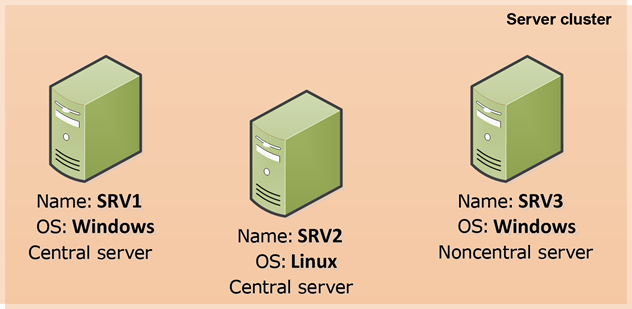 Fig. 10. Server cluster used for sample rules
Cluster specifications:
-
Number of working servers: 3
-
Fault tolerance level: 1
-
Number of main servers: 2 (SRV1 and SRV2)
-
Operating systems on working servers:
-
SRV1 server, Windows
-
SRV2 server, Linux
-
SRV3 server, Windows
-
Cluster infobases:
-
DemoDB,
-
WorkDB.
2.2.7.12. Assigning All Background Jobs to a Single Working Server
To assign all background jobs to the SRV1 working server, use the functionality assignment rules for SRV1 as described below:
-
Assignment rule object: Client infobase connection.
-
Rule type: Assign.
-
Infobase name: not specified.
-
Additional parameter value: BackgroundJob.CommonModule.
2.2.7.13. Assigning the Licensing Service to a Dedicated Working Server
To activate a multi-user client license for the computer running the SRV2 working server, assign the licensing service to this computer, and make sure no other service are assigned to this computer, use the functionality assignment rules for SRV2 as described below:
-
Rule 1:
-
Assignment rule object: Licensing service.
-
Rule type: Assign.
-
Infobase name: not specified.
-
Additional parameter value: not specified.
-
-
Rule 2:
-
Assignment rule object: Any assignment rule object.
-
Rule type: Do not assign.
-
Infobase name: not specified.
-
Additional parameter value: not specified.
-
Rule 1 will ensure that the licensing service is running on the SRV2 server. Rule 2 will ensure that only the licensing service is running on the SRV2 server (no other cluster services will be running on the SRV2 server).
When activating a software license via 1C:Enterprise server, specify SRV2 as the server name. Otherwise, the server cluster will not be able to use the license as it will be activated for another computer.
2.2.7.14. Prohibiting Assignment of the External Data Source Access Service to a Working Server
You must allow operation of the external data source access service on the SRV1 and SRV3 working servers and prohibit it on the SRV2 working server. To do it, specify the assignment rule for the SRV2 working server as described below:
-
Assignment rule object: External data source access service.
-
Rule type: Do not assign.
-
Infobase name: not specified.
-
Additional parameter value: not specified.
2.2.7.15. One Working Process Processing a Single Infobase
To configure the server cluster so that each infobase is processed by one working process, set the Number of infobases per process property for each working server to 1.
As a result, two working processes will be created on each server (6 in total, 2 working processes for each of the 3 working servers). In this case, one infobase will be processed by 3 working processes on 3 working servers.
2.2.7.16. Assigning Working Servers to Specific Infobases
Configure the server cluster so that the DemoDB infobase is processed only by the SRV3 working server and the WorkDB infobase is processed by two working servers: SRV1 and SRV2. To do it, specify the following rules:
-
For the SRV3 working server:
-
Assignment rule object: Any assignment rule object.
-
Rule type: Assign.
-
Infobase name: DemoDB.
-
Additional parameter value: not specified.
-
-
For the SRV1 and SRV2 working servers:
-
Assignment rule object: Any assignment rule object.
-
Rule type: Assign.
-
Infobase name: WorkDB.
-
Additional parameter value: not specified.
-
These rules will allocate all server cluster mechanisms: connections, background jobs, session data services, and so on.
2.2.7.17. Assigning Specific Background Jobs to Specific Working Servers
Configure the server cluster so that the SRV1 working server only runs reports, SRV2 runs the FullTextSearchUpdateIndex and SalesAggregateUpdate scheduled jobs, and SRV3 runs any other background jobs. To do it, specify the following rules:
-
For the SRV1 working server:
-
Rule:
-
Assignment rule object: Client infobase connection.
-
Rule type: Assign.
-
Infobase name: not specified.
-
Additional parameter value: BackgroundJob.GenerateReport.
-
-
-
For the SRV2 working server:
-
Rule:
-
Assignment rule object: Client infobase connection.
-
Rule type: Assign.
-
Infobase name: not specified.
-
Additional parameter value: BackgroundJob.CommonModule.FullTextSearchOperation.FulltextSearchIndexUpdate.
-
-
Rule:
-
Assignment rule object: Client infobase connection.
-
Rule type: Assign.
-
Infobase name: not specified.
-
Additional parameter value: BackgroundJob.CommonModule.AggregatesScheduledJobs.SalesAggregateUpdate.
-
-
2.2.7.18. Group Distribution of Background Jobs
Configure the cluster so that the SRV1 working server serves all background jobs that start from the ServiceJobsServer common module, and the SRV2 working server serves only the search in dynamic lists.
To do it, specify the following rules:
-
For the SRV1 working server:
-
Rule:
-
Assignment rule object: Client infobase connection.
-
Rule type: Assign.
-
Infobase name: not specified.
-
Additional parameter value: BackgroundJob.CommonModule.ServiceJobsServer.
-
-
-
For the SRV2 working server:
-
Rule:
-
Assignment rule object: Client infobase connection.
-
Rule type: Assign.
-
Infobase name: not specified.
-
Additional parameter value: BackgroundJob.DynamicListSearch.
-
-
2.2.7.19. Restricting Data Accelerator Startup
To restrict using Data Accelerator in the cluster:
-
Create two rules on any production server as follows:
-
Rule 1:
-
Assignment rule object: Any assignment rule object.
-
Rule type: Assign.
-
Infobase name: not specified.
-
Additional parameter value: not specified.
-
-
Rule 2:
-
Assignment rule object: Data Accelerator service.
-
Rule type: Do not assign.
-
Infobase name: not specified.
-
Additional parameter value: not specified.
-
-
-
For the rest of the production servers:
-
Rule 3:
-
Assignment rule object: Data Accelerator service.
-
Rule type: Do not assign.
-
Infobase name: not specified.
-
Additional parameter value: not specified.
-
-
If a server cluster consists of one production server, create the first two rules in the specified order. You cannot create one rule with the Do not assign type due to the assignment rule specifics.
2.2.7.20. Assigning User Sessions
Configure the cluster so that the SRV1 production server serves all sessions of the user named ExternalService (on whose behalf, for example, all HTTP and web services for external access to infobase data are performed), and the SRV2 server serves only users whose Assignment rule key is set to Analytics.
To do it, specify the following rules:
-
For the SRV1 working server:
-
Rule:
-
Assignment rule object: Client infobase connection.
-
Rule type: Assign.
-
Infobase name: not specified.
-
Additional parameter value: UserName.ExternalService.
-
-
-
For the SRV2 working server:
-
Rule:
-
Assignment rule object: Client infobase connection.
-
Rule type: Assign.
-
Infobase name: not specified.
-
Additional parameter value: UserAssignmentRuleKey.Analytics.
-
-
If the above rules are to be applied to only one infobase, fill the Infobase name field in the above rules. In this field, enter the name of the infobase for which these rules for allocating server cluster connections will be executed.
Please note that the Additional parameter value can be either the only value of UserName.<name> or the only value of UserAssignmentRuleKey.<name>. Combinations of values, regular expressions, and other ways to specify multiple parameter results are not supported.
2.2.8. Security Profiles
2.2.8.1. General Information
Functioning applications can use different external resources for their purposes: file system directories, COM objects (on Windows), add-ins, OS applications, and so on. However, for security reasons, applications might be restricted from accessing certain external resources. You might need to create a separate temporary files directory for each area of a separated infobase or specify a white list of Internet resources that the application can access.
To enable such restrictions, you can set up security profiles for the server cluster. Security profile is a set of explicitly defined permissions that allow using certain external resources (with a list of such resources), which can be assigned to infobases registered in the cluster. Security profiles are created by the cluster administrator and allow you to configure the following permissions:
-
Permission to use this profile as a security profile in safe mode. If this permission is enabled (see the Can be used as a safe mode security profile property), the name of this security profile can be specified in 1C:Enterprise language when enabling safe mode and attaching external reports and data processors.
-
Access to file system resources of the server (see Server file system resources).
-
Access to COM objects (only for Windows servers) (see Server COM objects).
-
Access to add-ins (see Add-ins).
-
Access to external modules (external reports, data processors, and extensions) and access to the Execute() operator and the Eval() function (see External modules).
-
Access to OS applications (see OS applications).
-
Access to Internet resources (see Internet resources).
-
Access the privileged mode. If this permission is enabled (see the Full access allowed: privileged mode profile property), the privileged mode can be enabled when this profile is used as the safe mode profile (see Privileged mode).
-
Access to cryptographic functions.
-
Extension of access rights (see Ошибка! Источник ссылки не найден.).
-
Extension of all configuration modules (see Extending all configuration modules).
To apply the security profile you created to a certain infobase, you need to specify the name of that profile in the infobase properties using cluster server administration tools. You can also specify the name of the profile to be used in safe mode in the infobase properties.
Some permissions allow you to specify a list of permitted resources. These permissions are:
-
Access to server file system resources
-
Access to COM objects (only for Windows servers)
-
Access to add-ins
-
Access to external modules
-
Access to OS applications
-
Access to Internet resources
-
Extension of access rights
-
Extension of all configuration modules
In this case, the following considerations apply:
-
If a check box (for example, "Access to Internet resources") is cleared in the security profile, Internet resources cannot be accessed from the infobase this security profile is applied to.
-
If this check box is selected in the security profile, the application has full access to Internet resources.
-
If assigned access is required, clear the check box and specify resources you allow access to. For some permissions, both white-list and black-list can be specified. Restriction lists for permissions are created in a number of different ways.
For detailed descriptions of specific permissions, see below.
2.2.8.2. Server File System Resources
Virtual directories are used to access server file resources. This implies that each security profile has a virtual file system where directories are created. Each virtual directory reflects the real file system according to certain rules. When the application needs to execute a file operation, a path to the file located in the virtual file system is specified in the respective function parameter. 1C:Enterprise translates the virtual directory to a physical one and generates a physical path to the file specified in the operation. The application cannot obtain any information on which physical path will be used to reflect the virtual directory.
If multiple virtual directories are specified in the security profile, the application can only access those resources. Attempting to access any other directory (both real and virtual) is impossible.
Virtual directories are used when calling the following 1C:Enterprise language methods:
-
Global context:
-
BinDir()
-
TempFilesDir()
-
ValueToFile()
-
ValueFromFile()
-
FileCopy()
-
MoveFile()
-
DeleteFiles()
-
FindFiles()
-
CreateDirectory()
-
SplitFile()
-
MergeFiles()
-
GetTempFileName()
-
-
Picture object:
-
File name-based constructor
-
Write()
-
-
BinaryData object:
-
File name-based constructor
-
Write()
-
-
TextExtraction object:
-
File name-based constructor
-
Change of FileName property
-
Write()
-
-
TextDocument object:
-
Write()
-
Read()
-
-
SpreadsheetDocument object:
-
Write()
-
Read()
-
-
FormattedDocument object:
- Write()
-
GraphicalSchema object:
-
Write()
-
Read()
-
-
GeographicalSchema object:
-
Write()
-
Read()
-
-
File object:
- File name-based constructor
-
xBase object:
-
File name-based constructor
-
OpenFile()
-
CreateIndex()
-
CreateFile()
-
-
XMLReader object:
- OpenFile()
-
XMLWriter object:
- OpenFile()
-
XMLCanonicalizingWriter object:
- OpenFile()
-
XSLTransform object:
-
LoadFromFile()
-
TransformFromFile()
-
-
FastInfosetReader object:
- OpenFile()
-
FastInfosetWriter object:
- OpenFile()
-
ZipFileWriter object:
-
File name-based constructor
-
Add()
-
Open()
-
-
ZipFileReader object:
-
File name-based constructor
-
Extract()
-
ExtractAll()
-
Open()
-
-
FileClientCertificate object:
- Default constructor
-
FileCertificationAuthorityCertificates object:
- Default constructor
-
HTMLWriter object:
- OpenFile()
-
HTMLReader object:
- OpenFile()
-
TextReader object:
-
File name-based constructor
-
Open()
-
-
TextWriter object:
-
File name-based constructor
-
Open()
-
-
CryptoCertificate object:
- File name-based constructor
-
CryptoManager object:
-
Sign()
-
VerifySignature()
-
Encrypt()
-
Decrypt()
-
GetCertificatesFromSignature()
-
-
DataHashing object:
- AddFile()
The following parameters describe a virtual directory:
- Logical URL. Address to be used by the application. This parameter must look like a beginning of a real path in the respective file system (for Windows and Linux). Paths used in the application can start only with a value that completely matches the logical URL value. For example, if the \storage string is specified as a logical URL, this virtual directory will be used when you specify the \storage\document.txt path in the application. However, it will not be used when you specify the storage\document.txt path. The logical URL value is unique within a single profile.
System methods use two predefined logical URLs:
-
/bin. Directory with runtime modules of the current 1C:Enterprise version. This virtual directory is used by the BinDir() method.
-
/temp. Temporary files directory. This virtual directory is used by the TempFilesDir() method.
-
Physical URL. URL that specifies the physical location of a logical URL in the file system of the server. It can include special placeholder characters. When executing file operations, 1C:Enterprise converts the logical URL into the actual file system address by replacing all placeholders. Each character sequence that is not allowed in a URL is replaced by an underscore ("_").
The following placeholders are allowed in the address:
-
%r. Reference name of the infobase.
-
%i. Infobase ID.
-
%z. String representation of the current values of current session separators in a format adopted for the /Z command-line option.
-
%s. Session number.
-
%c. Connection number.
-
%p. ID of the safe code execution mode.
-
%e. Directory with 1C:Enterprise runtime modules.
-
%t. Current directory with temporary OS files.
-
%u. Directory with application data of the current user.
-
%a. Directory with application data of all users.
-
%n. Name of the current infobase user.
-
%%. Percent sign (%).
-
Can read data. Defines whether files can be read from this virtual directory.
-
Can write data. Defines whether files can be written to this virtual directory.
Physical URL can point to directories located on 1C:Enterprise computer or network resources. You need to consider specifics of file system organization and network resource operations of the OS running the server.
When a session is closed, any physical directories specified with the %s placeholder are deleted. Similarly, when a connection is closed, any physical directories specified with the %c placeholder are deleted. Enabling safe mode for execution of code in 1C:Enterprise language has its own unique ID. When safe mode is disabled, any physical directories specified with the %p placeholder are deleted.
2.2.8.3. Server COM Objects
The cluster security profile can contain a list of COM object classes permitted for the application.
If the infobase references a security profile that restricts usage of COM objects, only COM object classes included in the list of COM object classes permitted for this profile can be used. The COM object used by the configuration corresponds to the item on the security profile list of permitted COM objects if the value of the COM object computer property matches and the non-null values of the File (moniker) and COM class ID properties also match. Any attempt to create an instance of any COM object not included in the list raises an exception.
The following parameters describe a permitted COM object class:
-
Name. Unique name of the COM object class. It is unique within one profile.
-
File (moniker). File moniker name. Used when calling the GetCOMObject() method with an undefined value of the NameOfCOMClass parameter. For more information about file monikers, see: https://docs.microsoft.com/en-us/windows/win32/com/file-monikers?redirectedfrom=MSDN.
-
COM class ID. String representing a COM object class ID. It is in the Windows registry format and without framing curly brackets. This value is used in the new COM object wizard and in the GetCOMObject() method.
-
COM object computer. Computer where a COM object can be created. Used by the new COM object constructor. To specify the current computer, use the localhost string. If the COM object can be created on any computer, leave the string empty.
2.2.8.4. Add-Ins
The cluster security profile can contain a list of add-ins permitted for the application. If the infobase references a security profile that restricts usage of add-ins, only the add-ins included in the list of add-ins permitted for this profile can be used. Any attempt to execute the AttachAddIn() method for an add-in not included in the list raises an exception. An empty list means that this profile does not permit any add-in usage.
The following parameters describe a permitted add-in:
-
Name. Unique add-in name. It is unique within one profile.
-
Checksum. SHA1 checksum of an allowed add-in converted to the base64 format.
To generate the checksum, you can use the DataHashing object and the Base64String() global context method.
To prepare permissions for a Native API add-in, you need to specify a separate permission for each platform type supported by the add-in. An add-in supporting all platforms has 4 permissions: for x32 and x64 Windows, and for x32 and x64 Linux.
2.2.8.5. External Modules
A cluster security profile can contain a list of external modules that can be accessed from the application code without enabling the safe mode. External modules include: external reports, external data processors, and configuration extensions. If the infobase references a security profile that restricts usage of add-ins, only those external modules included in the list of permitted modules can be used without enabling the safe mode. Any attempt to use an external module not included in the list without enabling the safe mode raises an exception. An empty list means that this profile does not permit any usage of external modules without enabling the safe mode. This profile item also controls whether the Execute() operator and the Eval() function can be used in safe mode. If the Full access allowed: external modules checkbox is cleared in the security profile, the Execute() operator and the Eval() function can be used in safe mode only (you need to enable the safe mode prior to every use of this operator or function). If the Execute() operator and the Eval() function are used in the application for internal purposes (with disabled safe mode), do not use any security profiles where the Full access allowed: external modules check box is cleared.
The following parameters describe a permitted external report or data processor:
-
Name. Unique external module name. It is unique within one profile.
-
Checksum. SHA1 checksum of an allowed external report or data processor converted to the base64 format.
To generate the checksum, you can use the DataHashing object and the Base64String() global context method. To generate the checksum for a configuration extension, use the API or Designer (Configuration – Configuration extensions – Actions – Show checksum).
2.2.8.6. OS Applications
A cluster security profile can contain a list of third-party applications that can be started from 1C:Enterprise. If the infobase references a security profile that restricts usage of third-party applications, only those third-party applications included in the list of applications permitted for this profile can be used. Any attempt to execute the RunApp() method for a third-party application or with parameters not included in the list raises an exception. An empty list means that this profile does not permit any usage of third-party applications.
The following parameters describe a permitted third-party application:
-
Name. Application name. It is unique within one security profile.
-
Command-line syntax. Application command-line syntax. It is a sequence of space-separated mask words. A mask word is a sequence of any characters and placeholders. If a mask word contains spaces, it must be enclosed in quotation marks.
The following placeholders are allowed:
-
%. Arbitrary sequence of characters.
-
_. Single character.
-
. File name. If a mask word starts with , the parameter is a virtual directory path. Before the command line is executed, the virtual directory name is replaced with the physical one.
-
\. Escape character. Place this character before a mask word to make it a common non-mask word.
The name of the application to be started, as well as each of its command-line parameters, are checked against the list of allowed applications. If a matching mask word is not found, the mask does not match the command line.
Example: the xcopy /temp/% /userdata/% mask is used to copy a file from the /temp virtual directory to the /userdata virtual directory.
Command-line parameters are separated by one or more space characters.
A string enclosed in quotes (") is treated as a single parameter. A sequence of words where the first and the last words contain an odd number of single quotation marks is treated as a single parameter. If only one word with quotation marks is found, everything from this word to the end of the string is treated as a single parameter. To put a quotation mark in a parameter not enclosed in quotation marks, use this pair of characters instead: \". To put a quotation mark in a parameter enclosed in quotation marks, use either of these pairs of characters: \" or "".
2.2.8.7. Internet Resources
A cluster security profile can contain a list of Internet resources that can be accessed from the application server code. If the infobase references a security profile that restricts access to Internet resources, the InternetConnection object cannot be used. The InternetMail, HTTPConnection, FTPConnection, and WSDefinitions objects can be used only to access resources included in the list of Internet resources permitted for this profile. Any attempt to access any resource not included in the list raises an exception. An empty list means that this profile does not permit any access to Internet resources.
The following parameters describe a permitted Internet resource:
-
Name. Resource name for its identification. It is unique within one security profile.
-
Address. Resource address without specifying the protocol.
-
Port. Number of the port used to interact with the resource. If the value is set to 0, any port can be used for interaction.
-
Resource type (protocol). Protocol used to interact with the resource. The following protocols can be specified (the character case is irrelevant):
-
imap. Email server using IMAP.
-
pop3. Email server using POP3.
-
smtp. Email server using SMTP.
-
http. Web server.
-
https. Secure web server connection.
-
ftp. FTP server.
-
ftps. Secure FTP server connection.
-
2.2.8.8. Privileged Mode
If a session is managed by a security profile in safe mode, operation in privileged mode depends on the following two security profile parameters: the privileged mode checkbox in the Full access allowed group and the Privileged mode roles property.
If the privileged mode check box is selected, the user is granted full access as soon as the privileged mode is enabled: access roles are no longer checked and all data access restrictions are removed.
If the privileged mode check box is cleared, system behavior depends on the Privileged mode roles property as follows:
-
The property has predefined roles. When privileged mode is enabled, access rights and data access restrictions in the current session are set according to the roles selected in the Privileged mode roles property. When the privileged mode is disabled (in any way), roles and data access restrictions existing before the privileged mode was enabled are restored.
-
The property has no predefined roles. In this scenario, roles and data access restrictions used before the privileged mode was enabled remain active. All right checks and data access restrictions will be applied.
Other parameters of the active security profile define available external resources.
-
Safe mode.
-
Privileged mode.
2.2.8.9. Cryptographic Functions
To use cryptographic functions on the server side, you need a specific security profile permission. If required check box is selected, you can use any methods of the CryptoManager object. Otherwise, any attempt to use these methods raises an exception.
The security profile permission affects the following methods of the CryptoManager object:
-
Encrypt()
-
Sign()
-
GetCryptoModuleInformation()
-
GetCertificatesFromSignature()
-
GetCertificateStore()
-
VerifySignature()
-
CheckCertificate()
-
Decrypt()
2.2.8.10. Extending All Configuration Modules
When the application runs in client/server mode and a specific security profile is specified when attaching an extension or profiles of both regular and safe modes are assigned to an infobase, the "server" extension part will be extended according to the respective profile. There are several properties responsible for extending the "server" extension part in the security profile:
-
To all module extensions. If this check box in the Full access allowed group is selected, all common server modules can be extended for all extensions applied using this security profile.
-
Modules available for extension. This property contains a comma-separated list of modules that can be extended.
-
Modules not available for extension. The property contains a comma-separated list of modules that cannot be extended.
The server part of extension includes:
-
Extensions of server methods of managed forms that were created using annotations (rather than property panel constructor)
-
Non-global server common modules
2.2.9. Server Cluster Security
2.2.9.1. General Information
When 1C:Enterprise runs in client/server mode, data security is achieved by ensuring that 1C:Enterprise data is only accessed using 1C:Enterprise tools. In this context, a number of major security areas can be defined.
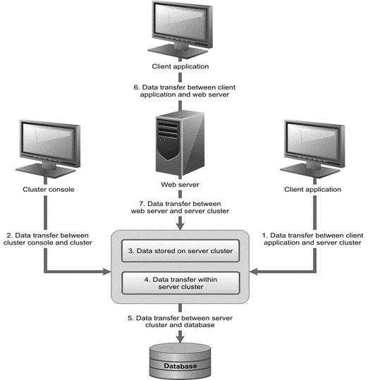
Fig. 11. General data security structure
All client applications and external connections access the 1C:Enterprise data only via 1C:Enterprise server cluster. For successful authentication, the user must enter their valid 1C:Enterprise username and password.
1C:Enterprise server cluster data processes infobase and internal data. The server cluster is therefore responsible for data security of the following areas (for area numbering explanation, see Fig. 11):
-
Data exchange between the client and server cluster (1)
-
Data exchange between the server cluster console and server cluster (2)
-
Data exchange between the server cluster and web server (7)
-
Internal data storage in the server cluster (3)
-
Data exchange within the server cluster (4)
The infobase is stored in a database. Infobase security, as well as data security during exchange between the server cluster and the database server, is provided by the DBMS (5).
When an infobase is connected via a web server, data security during exchange between the client application and web server is provided by the web server (6).
2.2.9.2. Security of Data Exchanged Between a Client and a Server Cluster
2.2.9.3. General Information
Security of data exchanged between the client and server cluster is achieved due to data encryption. Three security levels are available:
-
Never
-
Connection only
-
Always
The Never level is the least secure, the Always level is the most secure. Secure TCP/IP connection with RSA and Triple DES encryption is used.
2.2.9.4. “Always” Security Level
The Always security level provides full-range protection for data (including passwords) being exchanged between the client and the server cluster.
The client and server cluster interaction protocol is outlined below.
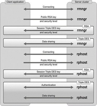 Fig. 12. "Always" security level
The same interaction protocol is used for the cluster manager (rmngr) and for the working process (rphost): once the connection is established, the first data exchange procedure is RSA encrypted while all subsequent data exchange uses Triple DES encryption.
The security level is specified when an infobase is created. This information is stored both on the client (in the infobase list) and in the server cluster (in the server registry). You cannot change the security level of an infobase after it has been created. The client application can, however, request that the security level be increased.
For that reason, when a connection is established, the client generates a private and a public RSA keys and sends the public key and security level specified on the client for this infobase to the server cluster. This is the target security level.
The server cluster selects the higher security level from the one sent by the client and one specified for this infobase in the cluster registry. This is the actual security level. Then, the server cluster generates a Triple DES session key and sends it (together with the actual security level) to the client, after encrypting it with the client's public key.
All subsequent data exchange is performed at the actual security level. Both the client and the server encrypt the transferred data using the Triple DES session key.
2.2.9.5. “Connection Only” Security Level
The Connection only security level provides partial protection for data (passwords only) being exchanged between the client and the server cluster. This security level offers good balance between safety and performance.
The infobase data is sent without encryption. This constitutes a negligible performance impact.
However, crucial information (passwords) is sent in encrypted form. Therefore, any malicious user that intercepts the data stream will not be able to read any significant amount of the infobase data. Password encryption prevents the malicious users to pass infobase authentication in order to gain full data access or perform any infobase operations.
The client and server cluster interaction protocol is outlined in fig. 13.
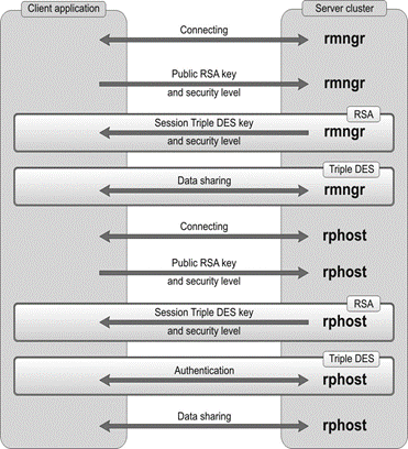
Fig. 13. "Connection only" security level
Once the connection is established, the first data exchange procedure is RSA encrypted while all subsequent data exchange uses Triple DES encryption until the authentication is completed. All data exchange after that moment is not encrypted.
2.2.9.6. “Never” Security Level
The Never security level offers the weakest protection at the lowest performance cost. Absolute majority of data is sent without encryption.
The client and server cluster interaction protocol is outlined below.
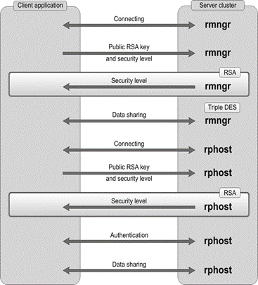 Fig. 14. "Never" security level
Once the connection is established, the first data exchange procedure is RSA encrypted. All data exchange after that moment is not encrypted.
If the client application and server cluster are located on the same computer and security level is set to Never, all data is sent without encryption.
2.2.9.7. Security of Data Exchanged Between the Server Cluster Console and a Server Cluster
Security of data exchanged between the server cluster console and server cluster is achieved due to data encryption. The following security levels are used: Never, Connection only, and Always.
The server cluster console interacts with the server agent (ragent process). Required security level is specified at server agent startup. The server agent selects and applies the higher security level from the security level specified at startup and security levels of all clusters located on the main server. Cluster security level is specified when the cluster is created (interactively or programmatically).
2.2.9.8. Security of Data Stored in a Server Cluster
2.2.9.9. General Information
A server cluster uses internal data, such as a list of server clusters, cluster registries, and more. All internal data is stored in files in two directories:
-
Application data directory
-
Temporary files directory
The general policy of handling the internal data is that only the cluster manager (rmngr) and the server agent (ragent) can access internal data of the server cluster. Working processes (rphost) access internal data only via the cluster manager. Since these processes can run configuration code snippets, they are considered potentially dangerous.
2.2.9.10. Security of Application Data Directory
During 1C:Enterprise server cluster deployment, a special directory, which is used to store 1C:Enterprise server cluster files, is created in the application data directory.
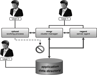 Fig. 15. Application data directory
Full rights for this directory are granted to the user account USR1CV8 that runs the server agent by default. No other users are allowed to access this directory. The server agent starts the cluster manager under the same user account that was used to start the server agent. For more details about the rights required for the USR1CV8 user, see User rights.
The server agent also starts working processes. By default, a working process is started under the same user account that was used to start the server agent. However, an additional operating system user account can be created that will start working processes only. This technique is used to prevent the configuration code from directly accessing internal data.
To start a working process under a different user account (not the user account that was used to start the server agent), you need to place swpuser.ini file in the application data directory for the server agent user.
2.2.9.11. Security of Temporary Files Directory
Temporary files data is protected in a different manner. As the system temporary files directory is a shared directory, the access rights for each temporary file are granted separately.
When a temporary file is created by 1C:Enterprise server cluster, the USR1CV8 user is granted full rights to the created file. No other users are allowed to access this file. This means that all the data stored in temporary files is protected from unauthorized access.
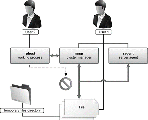 Fig. 16. Access restriction
2.2.9.12. Encryption of Passwords Stored in Internal Data of Server Cluster
Server cluster administrator passwords and infobase access passwords are encrypted and stored in the server cluster. SHA1 and AES128 algorithms are used for password encryption.
-
SHA1 is used to store passwords that 1C:Enterprise checks (for example, cluster administrator password, main server administrator password). The original text of the stored passwords cannot be restored. You can only check if the checksum of the entered password matches the stored checksum.
-
AES128 is used to store passwords that can be decrypted (for example, DBMS passwords).
2.2.9.13. Security of Data Exchanged Within a Server Cluster
Security of data exchanged within a server cluster (for example, between working processes and the cluster manager) is achieved due to data encryption. The following security levels are used: Never, Connection only, and Always.
The cluster security level is applied to interactions between a working process and the cluster manager. The security level applied for interaction between the server agent and cluster manager is the higher security level selected from the security level used at server agent startup and the security level of the cluster served by this manager.
2.2.9.14. Security of Data Exchanged Between a Server Cluster and a DBMS
Security of the data channel between a server cluster and a DBMS is provided by DBMS tools. All supported database management systems can encrypt the traffic between client components in a cluster and the DBMS. All supported database management systems can exchange data over SSL.
2.2.9.15. Security of Data Exchanged Between a Client and a Web Server
SSL or TLS encryption protocols are used to secure the channel between a web client (or a thin client) and the web server.
These protocols are supported by web server HTTPS connection. This requires that a valid server certificate is available on the server, guaranteeing authenticity of the server public key used for data encryption. Client certificates that ensure client authenticity can be used as well.
You need to consider restrictions related to the operating system running the application. For example, the Linux client does not support client certificates from the Windows certificate store.
2.2.9.16. Security of Data Exchanged Between a Web Server and a Server Cluster
Security of data channels between a server cluster and a web server is provided by data encryption algorithms available in 1C:Enterprise: RSA and Triple DES.
Connection between a cluster and a web server is only secured by the cluster in accordance with the properties of the connected infobase (for details, see Security of data exchanged between a client and a server cluster).
2.2.9.17. Main Server and Cluster Administrators
1C:Enterprise server cluster is administrated either with or without administrator authentication.
If authentication is disabled, any user connected to a main server of the cluster can perform any administrative actions both on the main server and any cluster on this server. By default, administrator authentication is disabled when 1C:Enterprise server cluster is deployed.
To restrict the number of users allowed to perform administrative tasks, you can create separate administrator lists for the main server (see Operations with the list of main server administrators) and for each cluster on this server. Areas of authority of main server administrators and cluster administrators do not overlap.
Users authenticated as main server administrators can perform administrative tasks on the main server. However, to perform any administrative tasks on a specific cluster, the user must be authenticated as administrator of this cluster. Authentication as the server administrator is not required for this purpose.
Main server/cluster administrator authentication is enabled automatically as soon as at least one administrator is added to the main server/cluster administrator list.
If authentication is enabled, users not authenticated as main server administrators can only view or modify main server connection parameters in the server cluster administration console.
User not authenticated as cluster administrators can only view cluster properties. Moreover, these users can also create objects in a cluster, infobase, and so on using 1C:Enterprise language expressions, but they cannot register these objects in the cluster.
2.2.10. Infobase Locks
To ensure consistent interaction with infobases, 1C:Enterprise relies on a locking feature for concurrent operation with these components:
-
Configuration
-
Infobase
-
Database
For more details on the feature, see the section that covers the server cluster administration utility (see Operations with the list of locks).
Two types of locks are implemented: shared and exclusive. Shared locks support multiple concurrent sessions. Exclusive locks are used when you need to prevent data from being changed by other sessions.
System administrators need to clearly understand when exclusive locks (exclusive mode) are required. In some situations, exclusive locks for a certain configuration or infobase are enabled and disabled automatically (see below). The exclusive database lock may be enabled or disabled both automatically and manually by calling the SetExclusiveMode() method.
Please note that these locks are intended for database access control in 1C:Enterprise. For example, enabling the exclusive lock for a database will not prevent third-party applications from accessing the database as their access methods do not rely on 1C:Enterprise features.
More on exclusive locks:
-
Configuration lock is set automatically as Designer starts, preventing other Designer instances from accessing the infobase.
-
Infobase lock prevents any other sessions from starting while a session is running. The lock is enabled upon:
-
Database configuration update
-
Infobase import
-
Infobase export
-
Creation of initial infobase image
-
Infobase conversion for a new platform version
-
Testing and debugging
-
-
Database lock allows only one Designer session and one session of an arbitrary kind. The lock is enabled upon:
-
Execution of the SetExclusiveMode() method. It is required when you want to make consistent changes to the database, but the changes you make cannot be made in a single transaction. For example, in case of bulk deletion of objects from a large infobase.
-
Batch posting of documents (only for thick client)
-
If any internal infobase connections are open, these connections will not prevent you from enabling the exclusive mode (both for the infobase and the database).
Any open sessions (except for cluster console sessions) will prevent you from enabling the exclusive mode since each session specifies an active user. Moreover, when you enable the exclusive mode, all infobase connections with no sessions assigned will be terminated implicitly. If the exclusive mode is enabled for infobase or database access, no new sessions can be opened.
If any web servers are connected to this infobase, enabling the exclusive access will result in requests sent to these servers to clear the connections pool.
2.2.11. Working Process Load Statistics
For each working process, the server cluster calculates a set of parameters that describe the load of this working process. All these parameters are calculated for an approximate 10-minute period:
-
Average server cluster response time
-
Average time spent by server cluster
-
Average time spent by DBMS
-
Average time spent by lock manager
-
Average number of client threads
The average server cluster response time is the time spent by the server cluster to process one client connection. It consists of several components:
-
Time spent by the working process
-
Time spent by the DBMS
-
Time spent by the lock manager
A working process handles each client connection in a separate thread. So, a working process can run multiple client threads at the same time. Generally, the number of such concurrent threads is less than the number of connections (because not all the connections are permanently active). The average number of client threads indicates the 24-hour average number of threads processed by the server simultaneously.
2.2.12. Cluster Monitoring System
To ensure uninterrupted server cluster operation, all cluster components must be monitored and emerging issues must be resolved without delay. To address such issues, you can use the cluster monitoring subsystem implemented in the server cluster. The subsystem collects cluster process status information on a regular basis. Generally, "process" means any server cluster component: server agent (ragent), server manager (rmngr), or working process (rphost). The term "process" will be clarified in the context where necessary. The list of collected and analyzed parameters includes:
-
Process connection check.
-
Calculation of available performance of a working process (see Available performance of a working process).
-
Process memory amount check (applicable to the cluster manager and a working process). The actual meaning of "memory occupied by a process" depends on which operating system the server cluster is running. A "process" refers to a working process or cluster manager. In documentation sections devoted to memory control, "memory occupied by a process" will always be used without specifying the used operating system. The phrase has the following meaning:
-
On Linux: the sum of the vmSwap and vmRSS indicators values of information about the memory used by the process.
-
On Windows: the PagefileUsage value of the PROCESS_MEMORY_COUNTERS structure.
-
-
Monitoring of working processes removed from the cluster registry.
Some operations (such as process memory check) are performed via respective server agents, which also tests operability of these agents.
Checks are made every 5 seconds. The connection check timeout is 20 seconds. The checks are performed consecutively, meaning that a check does not start until the previous check has completed. Negative check results are written to the technological log using the ATTN event.
The amount of memory is checked by comparing the total amount of memory occupied by all working processes and cluster managers (the meaning of this term is described earlier in this section) with the server cluster settings:
- The Temporarily allowed amount of process memory production server parameter. If the parameter is set to -1, this check is not performed. If the parameter is set to 0, 80% of the production server computer's RAM is considered to be the parameter value.
If the amount of used memory exceeds the temporarily allowed amount of memory, new connections are no longer assigned to the production server. If the Period of exceeding the process memory threshold production server parameter is not set to zero, after this interval, the used RAM of the server processes and the value of the Temporarily allowed amount of process memory parameter are compared again. If the amount of used memory still exceeds the temporarily allowed amount of memory, the required number of working processes will be restarted (not abnormally) starting with the one consuming the largest amount of RAM, so that the amount of memory consumed by the remaining working processes and managers does not exceed the Temporarily allowed amount of process memory parameter value.
- The Critical amount of process memory production server parameter. If the parameter is set to -1, this check is not performed. If the parameter is set to 0, 95% of the production server computer's RAM is considered to be the parameter value.
If the amount of used memory exceeds the value of this parameter, the required number of working processes will be terminated (and then restarted) starting with the one consuming the largest amount of RAM, so that the total amount of memory consumed by the remaining working processes and managers does not exceed the set value. In case of an abnormal termination of processes, dump recording will be controlled by the Write process dump when critical memory amount is exceeded production server parameter.
At each iteration of cluster state monitoring, if critical amount of processes memory is exceeded, the ATTN event is recorded to the technological log along with IDs of all cluster processes and their memory amount.
Processes that do not meet the monitoring requirements (the available performance indicator is excluded from the analysis) are considered problematic. The monitoring feature then analyzes the Terminate corrupted processes and Terminate corrupted processes in cluster parameters. The first parameter (Terminate corrupted processes) allows the cluster to terminate cluster processes (by means of the used operating system) that could not be completed normally. The second parameter (Terminate corrupted processes in) determines the time that must pass from the moment when the cluster "understands" that the process was not terminated normally to the moment when its process is forcibly terminated by the operating system.
Hung up processes will never be forcibly terminated by means of the operating system if the Terminate corrupted processes parameter is cleared or the Terminate corrupted processes in parameter is set to 0.
Processes running on additional servers are terminated by sending requests to corresponding cluster agents.
Crash dumps are created according to the following rules for creating dumps in the 1C:Enterprise platform:
-
On Windows, settings from logcfg.xml are used.
-
On Linux, the OS settings are used, and the crash dump recording starts by sending a signal to the SIGABRT process. In this case, the standard crash dump is performed by the SIGSEGV signal.
Only the main server agent can send requests to cluster processes. Additional server agents are used to send requests to processes running on additional working servers. If a server agent connection error occurs, error messages are recorded to the technological log of main server agent.
Server calls (recorded in the technological log as CALL events) occur on a regular basis during normal operation of the server cluster. Errors of various nature (recorded in the technological log as EXCP events) can occur during these calls. However, an EXCP event recorded in the technological log does not automatically mean an actual server error. For example, when you select a working port from the available port range, each occupied port generates an EXCP message although no actual error has occurred.
When you monitor working processes removed from the cluster registry, a process is considered to have issues if it is not completed within 7.5 seconds after removal from the cluster registry.
The server cluster monitoring system described above might help you resolve the following issues:
-
"Hangup" of server processes in computer memory both during operation and when attempting to terminate a process.
-
Obsolete information on memory used by a working process displayed in the cluster console.
-
Increased memory consumption by cluster processes.
-
Server cluster parameters (see Adding clusters).
-
Production server parameters (see Adding production servers to a cluster).
2.2.13. Location of Cluster Manager Service Files
You can find the service files of the server cluster on a particular production sever in the server data directory. The path to this directory is specified as a value of the /d command of the command-line option for starting the server agent.
If a cluster is already created on a main server computer, always verify that the specified path to the directory with service files of the server cluster is correct when you change the start mode of the server agent (as a service or as an application) or when you change the user account used to run the server agent. If the server agent cannot find the server registry during startup, it creates a new cluster on the server.
On Windows, the location of the server data directory depends on how 1C:Enterprise server is started during installation:
-
Run as a service. In this case, the server agent will be first started during the system installation. The service will be started under the user account selected during the installation. Service files of the server cluster will be located in the <root installation directory>\srvinfo directory. This directory will be explicitly specified in the service parameters, in the /d command of the command-line option for starting the server agent.
-
Run as an application. The server is not started during the installation. Run the server agent manually after the installation is completed. If the /d command is not specified at startup, the server data directory will be the following directory: %LOCALAPPDATA% \1C\1cv8.
On Linux, you can find the server data directory in the /home/usr1cv8/.1cv8/1C/1cv8 folder (short name: ~/.1cv8/1C/1cv8). To change the directory, use the /d command of the command-line option for starting the server agent.
- Running the server agent (see Running the server agent).
2.3. Linux Operation Specifics
When 1C:Enterprise server cluster runs on Linux computers, the following limitations apply:
-
Working processes of 1C:Enterprise server cluster cannot interact with Microsoft SQL Server DBMS.
-
Working processes of 1C:Enterprise server cluster cannot interact with COM objects. Server modules interacting with COM objects can be compiled, but an attempt to run such module will result in an error message.
-
Kerberos authentication (the Windows version supports NTLM that ensures authentication without PDC) and/or username and password authentication are supported.
-
Features of the InternetConnection object are unavailable.
To be able to use certain features, 1C:Enterprise server running on Linux requires specific libraries. For a list of necessary libraries and features that require these libraries, see Required libraries on Linux.
Chapter 3. Installing System Components
3.1. Installing 1C:Enterprise Server
3.1.1. General Information
1C:Enterprise is a collection of modules used to develop and use applications (configurations) for enterprise accounting and business activities automation and the configuration or configuration collection.
1C:Enterprise modules are universal and compatible with any configuration (within the scope of the corresponding License Agreement).
A security driver preventing unauthorized access is installed together with 1C:Enterprise.
The installer allows you to install multiple 1C:Enterprise versions on a single computer, select components to install, and select 1C:Enterprise server installation mode.
3.1.2. Installation Options
Install 1C:Enterprise server cluster using an installer specific to each supported operating system: Linux OS family (hereinafter referred to as "Linux") and Windows OS family (hereinafter referred to as "Windows"). The server cluster is unavailable on macOS.
For Windows-based installations, use a standalone installer. Depending on the rights of the user performing the installation and the installation parameters, the installation can be performed in two modes: "for computer" or "for user".
1C:Enterprise supports several processor architectures for Linux. There are several ways to install the system. You can use a special installer or the package manager of the used operating system. The difference between these options:
-
The installer. A package manager of the operating system is not used in the installer. The installer has a graphical user interface. When using the command-line installer (batch installation), use the startup command-line parameters to select the components to install. The installer is available only for operating systems running on x86/x86-64 processors.
-
The package manager. A standard package manager of the used operating system is used for installation. To select components to install, choose preferred installation packages. There is no graphical user interface. This option is available for all supported processors. This is a more common option for Linux network administrators.
Before installation, please make sure that your computer is virus-free, the hard drive does not contain any errors, and enough disk space is available for the installation.
-
Installation for Linux.
-
Installation for Windows.
3.1.3. Installation on Linux
3.1.3.1. Rules to Name Distribution Files
The installation using the installer is not compatible with the installation using the package manager. In other words, if you install 1C:Enterprise using the package manager, delete the system using the package manager. If you install it using the installer, you can delete the system using the appropriate tool available in the directory of a specific version.
- File names when using the installer
- To install 1C:Enterprise on Linux running on an x86/x86-64 processor, use an installer created based on VMware InstallBuilder. The following installers are available:
- 1C:Enterprise 8. Installs any components. 32-bit and 64-bit versions of the installer are available.
The installer is located in a ZIP archive. ZIP archive and the installer have the same names (accurate to the extension). Names of the archive and the installer look as follows: setup-full-A.B.C.D-arch.ext, where:
-
A.B.C.D. Full number of 1C:Enterprise version whose installer is used.
-
arch. Architecture of 1C:Enterprise version to be installed:
-
i386. x86 processors.
-
x86_64. x86-64 processors.
-
-
ext. File extension.
-
zip. Archive of the installer and accompanying files.
-
run. Installer.
-
So, if the installer name is setup-full-8.3.24.100-x86_64.run, it is used to install a 64-bit version 8.3.24.100 of 1C:Enterprise, which will allow installing all system components. You can install the 1C:Enterprise server cluster only using the full installer version.
The ZIP archive also contains the installAsRoot executable file. The application simplifies the system installation process for an inexperienced user. If you run this application, the following will happen:
-
The application checks whether you have superuser rights (root).
-
If you do not have them, the acquisition of these rights will be initiated. To get the rights, enter the superuser password in the dialog box opened by the installAsRoot application.
-
If the password is correct, the installer with the superuser rights will be started in interactive graphic mode.
For an experienced user, the installAsRoot application startup is similar to the following command-line option:
sudo ./setup-*.runIn this example, "*" refers to the remaining part of the installer name described earlier in this section. If you run installAsRoot in a directory that has several run files, the installer whose file name is the first in the search results for files by the "setup-*.run" mask will be started.
Below, you can find out how to use a Linux installer.
- File names when using the package manager
- When you use a package manager, the 1C:Enterprise distribution package for Linux is provided in several packages. These packages are used to install both client applications and server clusters. Package files have the following names: 1c-enterprise-<version1>-<add-in>_<version2>.<arch>.<extension>, where:
-
<add-in>:
-
client. 1C:Enterprise client applications (thick client and thin client).
-
thin-client. 1C:Enterprise thin client (file infobase mode is not supported).
-
common. Common 1C:Enterprise add-ins.
-
server. 1C:Enterprise server add-ins and the integrity monitoring utility.
-
ws. Adapter for publishing a web client and 1C:Enterprise Internet services on Apache HTTP Server of supported versions.
-
crs. Configuration repository server.
-
An add-in name can end with the "-nls" suffix. This means that a package with this name contains additional national resources (in addition to Russian and English localizations) for the respective package. You can find the server add-in in two files: server (the server and resources in Russian and English) and in server-nls (additional national resources).
-
-
<version1>. Full version number of 1C:Enterprise package. All version elements are dot-separated. For example, for 1C:Enterprise version 8.3.22.100, version1 of the package name will contain the 8.3.22.100 string.
-
<version2>. Full version number of 1C:Enterprise package. The first three number elements are dot-separated. The last (fourth) number element is preceded by a hyphen ("-"). For example, for 1C:Enterprise version 8.3.22.100, version2 of the package name will contain the 8.3.22-100 string.
-
<arch>. Processor architecture for which this package is used:
-
aarch64. ARM64 processors (RPM version).
-
amd64. x86-64 processors (DEB version).
-
arm64. ARM64 processors (DEB version).
-
e2k. E2K processors (RPM version).
-
e2k-8c. E2K processors (DEB version).
-
i386. x86 processors.
-
x86_64. x86-64 processors (RPM version).
-
-
<extension>:
-
rpm. RPM package version.
-
deb. DEB package version.
-
If necessary, the required package file name is generated according to the rules above. If the name of the package you install is required, it is specified based on the add-in name. For example, the name of the common package for DEB version 8.3.22.100 looks as follows: 1c-enterprise-8.3.22.100-common_8.3.22-100-arm64.deb.
3.1.3.2. Installing Using the Installer
3.1.3.3. About Installer
3.1.3.4. General Information
To begin the installation, start the previously received installer (*.run file). Before you start the installer, make sure it has the execution access right. The access right must be granted to the current user. If necessary, you can configure the access right for a group and other users. To set the execution right, use the chmod operating system command or a dialog box of file properties in the graphical interface. Setting the right might require superuser rights (root).
You can start the installer either in interactive or batch mode. In this section, you can read about the installation in interactive mode.
The installer is an installation wizard. You can proceed through the wizard pages by clicking Next >. On every page of the wizard, provide information required for 1C:Enterprise installation. The installer details will contain the pages to be ignored if you select the "for user" installation mode.
Before the installer starts, the user will be prompted to select the language in which the installer will generate its interface. The same language will be selected to install the respective interface.
The language list contains only those languages in which user interfaces of 1C:Enterprise applications are implemented.
During the installation, the installer might display a list of packages required for the correct operation of 1C:Enterprise. This list is generated if the installer has not found the packages on the computer. Manually install the missing packages (from the displayed list) using the package manager of your operating system. The installation requires superuser rights (root).
Every wizard step is briefly described below. The examples illustrate installation of the full 64-bit 1C:Enterprise distribution package.
3.1.3.5. Welcome Screen
The 1C:Enterprise installation wizard starts with the welcome window.
3.1.3.6. Selecting Components
On this page, you need to select components to be installed and an installation directory. The component list depends on what exactly you need to have installed. Some standard installation scenarios are described in a special documentation section (see Typical 1C:Enterprise installation scenarios).
Select components using the check box next to the component description.
You can install the following components:
| Component | Brief description |
|---|---|
| 1C:Enterprise | Main 1C:Enterprise components, including components for file infobase operations. |
| 1C:Enterprise – Thin client | Thin client components only for client/server mode. |
| 1C:Enterprise – Thin client, file mode | Thin client components, including components for file infobase operations. |
| 1C:Enterprise 8 server | 1C:Enterprise server components, including the administration server and the administration utility. |
| Web server extension modules | Web server extension modules required for web client and web services. |
| 1C:Enterprise server administration | Administration server of 1C:Enterprise server cluster. |
| Additional interfaces | User interfaces in various languages. The English interface is installed by default and cannot be uninstalled. |
| 1C:Enterprise configuration repository server | 1C:Enterprise configuration repository server components. |
| Additional administration functions | Administrative console utility. |
| Thin client distribution packages | Allows you to install client application distribution packages.
The item becomes available when the following conditions are met:
|
| Liberica JRE | Java Runtime Environment (JRE) is minimal virtual machine implementation required to develop Java applications without a compiler and other development tools. JRE is used, for example, by the optimized feature for updating the database configuration (v2) or the licensing utility. |
| Integrity monitoring | Data integrity monitoring utility. |
3.1.3.7. Starting Installation
Click Next > to start the installation procedure that:
-
Creates required directories.
-
Copies files for selected components.
-
Creates configuration files.
-
Registers server software components.
-
Creates shortcuts in the application list to start 1C:Enterprise applications.
The installation procedure is displayed with an indicator. Notes to the indicator describe the actions being executed.
3.1.3.8. Installation Completion
Once the installation is completed, the installer notifies the user of it.
Click Finish to start the installation process. Before the installation of 1C:Enterprise, the following will be made:
-
An attempt to install the add-ins required for 1C:Enterprise operation if these add-ins are absent on the computer or there are versions that do not meet the 1C:Enterprise system requirements.
-
An attempt to install True Type fonts from Microsoft Core Fonts for Web. The installation will be performed as follows:
-
The installer searches for the installed package with the required fonts on the current computer.
-
If no fonts are found, the fonts will be installed from the official repository of the used operating system.
-
If the official repository does not have the required fonts, they will be installed from the following sources:
-
The same actions will take place during the batch installation.
Once the installation is completed, 1C:Enterprise is ready for use.
3.1.3.9. Batch Installation
Use the installer to install 1C:Enterprise both in interactive mode and batch mode. In this mode, installation can be performed without the window manager, completely in console mode. Batch installation is applied when you update the client application.
Enable batch mode by specifying the --mode unattended command in the installer command line. To specify components to be installed, use the --enable-components command. Components to be installed are listed by comma-separated parameters of this command. The following parameters are available:
| ID | Description | |
|---|---|---|
| additional_admin_functions | Install the administrative console utility. | |
| client_full | Install thick client with access to Designer operations. | |
| client_thin | Install thin client without access to file infobase operations. | |
| client_thin_fib | Install thin client with access to operations in any infobase mode. | |
| config_storage_server | Install configuration repository server. | |
| desktop_icons | Install shortcuts for various 1C:Enterprise add-ins. | |
| integrity_monitoring | Install the integrity monitoring utility. | |
| liberica_jre | Install Java Runtime Environment (JRE). | |
| server | Install 1C:Enterprise server cluster. | |
| server_admin | Install the administration server of the 1C:Enterprise server cluster. | |
| ws | Install web server extension modules. | |
| Install the application interface in a language that matches the specified ID: | ||
| ar | Arabic | |
| az | Azerbaijani | |
| bg | Bulgarian | |
| de | German | |
| el | Greek | |
| es | Spanish | |
| fr | French | |
| hu | Hungarian | |
| hy | Armenian | |
| it | Italian | |
| ka | Georgian | |
| kk | Kazakh | |
| lt | Lithuanian | |
| lv | Latvian | |
| pl | Polish | |
| ro | Romanian | |
| ru | Russian | |
| tk | Turkmen | |
| tr | Turkish | |
| uk | Ukrainian | |
| vi | Vietnamese | |
| zh | Chinese | |
When you specify the interface language to be installed, note that the English interface is installed by default. You do not need to specify English upon installation.
Let's consider a simple example. Perform the installation with the following parameters:
-
1C:Enterprise server cluster, administration tools, JRE, and web server operations.
-
1C:Enterprise version 8.3.24.100.
-
Install the Russian and English (default) interface languages.
-
Perform the installation for a 64-bit operating system.
For these parameters, use the installer for the full version. The installation command line will look as follows:
setup-full-8.3.24.100-x86_64.run --mode unattended --enable-components server,ws,server_admin,liberica_jre,ruAs noted earlier, the installer is based on VMware InstallBuilder. This documentation contains only system commands that are required to install 1C:Enterprise. For more information about other commands, see VMware InstallBuilder user documentation.
3.1.3.10. Installing Using the Package Manager
Systems running on Linux use a lot of package managers that have different names and used commands. For more information on which commands to use to install the software from files, see the documentation of a package manager that is used to install your operating system.
During installation, consider the following dependencies between packages:
-
common has no dependencies.
-
server depends on common.
-
ws depends on common.
-
crs depends on common, server, and ws.
-
client depends on server.
-
thin-client has no dependencies. No other 1C:Enterprise packages are required for a thin client. It conflicts with the common package. You can install either thin-client or other packages.
-
National resource packages depend on their package.
To install a package, first install all the packages that this package depends on. For example, to install the 1C:Enterprise thick client and Designer, first install the common and server packages, and then install the client package.
3.1.4. Installation for Windows
3.1.4.1. Available Installers
The following installers are available:
-
1C: Enterprise 8. Allows you to install any system component, including the system server. 32-bit and 64-bit versions of the installer are available.
-
1C:Enterprise 8 (x86-64) Server. Allows you to install only a 64-bit 1C:Enterprise server. Only 64-bit version of this installer is available.
All installers offer similar user experience. However, this documentation describes only 1C:Enterprise 8 (x86-64) Server installer.
3.1.4.2. General Installer Information
3.1.4.3. General Information
An installation wizard carries out the installation procedure. You can proceed through the wizard pages by clicking Next >>. To start the wizard, run setup.exe from the directory containing the distribution package you have selected. On every page of the wizard, provide information required for 1C:Enterprise installation.
When you start setup.exe using the /S parameter, installation is performed in silent mode. In this case, the installation mode will be defined first. Then its parameters will be obtained from the 1cestart.cfg file that matches the defined installation mode. If this file is not available, the default parameters will be used. Then 1C:Enterprise will be installed in the defined installation mode with the defined parameters.
Every wizard step is briefly described below.
3.1.4.4. Specifying Installation Mode
To select an installation mode, analyze the following data:
-
Value of the InstallForUser parameter of the 1cestart.cfg configuration file and the ALLUSERS parameter of the installer startup command line.
-
Access rights of the user installing 1C:Enterprise.
After the analysis, select the installation mode. The "Parameter value" column (in the table below) contains the resulting installation mode value obtained considering priorities. The resulting parameter value is determined as follows:
-
Parameter value is not specified (first-time installation). In this case, the parameter value is 0.
-
1cestart.cfg configuration file contains a value, the installer command line is blank. In this case, the parameter value is equal to the value from the 1cestart.cfg configuration file.
-
Installer startup command line contains the ALLUSERS parameter. In this case, the parameter value is equal to the value from the command line regardless of the 1cestart.cfg configuration file.
The user is considered to have administrator rights if at least one of the following requirements is met:
-
User is a local administrator of the personal computer.
-
User is a member of the local administrators group.
-
User has the right to install applications (the AlwaysInstallElevated policy).
Installation mode options are shown in the table:
| Parameter value | Administrator | User |
|---|---|---|
| 0: installation depends on access rights | C | D or U |
| 1: install "for computer" | C | D or C |
| 2: install "for user" | U | D or U |
| 3: install "for user" without questions | U | U |
Information to the table:
-
C. Installs "for computer" without providing the user with a choice.
-
U. Installs "for user" without providing the user with a mode choice.
-
D. Opens a dialog box where the user can select an installation mode.
-
If the user does not have administrator rights and the installation mode is between 0 and 2 (inclusive), "D" mode is selected for interactive installation and the second mode is used in other cases.
-
If a mode that requires an administrator password is selected during the installation and the current user does not know this password, the installation cannot be performed.
Depending on the selected installation mode, different directories will be used in further installer dialog boxes as default directories to install the system:
-
Installation "for computer": %PROGRAMFILES% or %PROGRAMFILES(x86)%.
-
Installation "for user": %LOCALAPPDATA%\Programs. You cannot use this mode to install 1C:Enterprise 8 (x86-64) as it includes only a 64-bit server cluster.
To ensure that installation "for user" is successfully completed, Windows must contain an installed Microsoft Visual C++ Re-distributable package included in 1C:Enterprise version to be installed (file: vc_redist.x86.exe or vc_redist.x64.exe). In any case, the installation of this package requires local administrator or network administrator rights.
If the installation mode must be selected by the user after the actions described above, the User text is the actual name of the user that performs the installation.
Once the user confirms their choice in the dialog box, the installation mode is saved to the 1cestart.cfg configuration file.
- 1cestart.cfg configuration file.
3.1.4.5. Welcome Screen
This is the starting window of the 1C:Enterprise installation wizard.
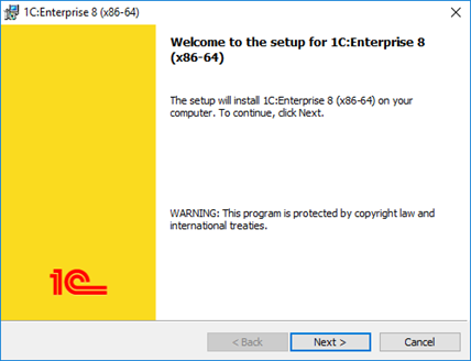 Fig. 17. Welcome screen
3.1.4.6. Selecting Components
On this page, you need to select components to install. The component list depends on what exactly you need to have installed. Some standard installation scenarios are described below.
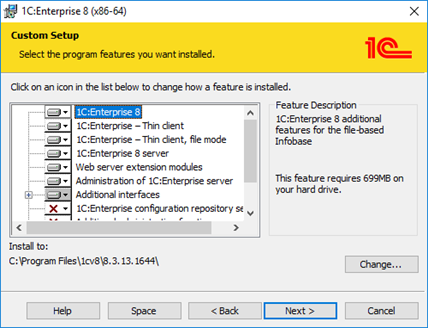 Fig. 18. Selecting components
If a component needs to be installed, select it in the list. If a component is not required, do not select it. To select a component, click an icon to the left of its name or press Spacebar. Select the item you need.
 Fig. 19. Component installation menu
Components to be installed or skipped are displayed as shown in fig. 20.
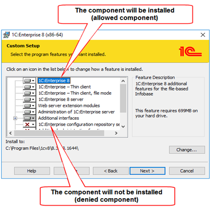
Fig. 20. Components to be installed or skipped
The following elements are numbered in the figure:
-
Component that will be installed on the user computer (selected component).
-
Component that will not be installed on the user computer (skipped component).
You can install the following components:
| Component | Brief description |
|---|---|
| 1C:Enterprise server access components | 1C:Enterprise server cluster component that allows you to connect to the server cluster using the cluster management console (available in the full system distribution package). |
| 1C:Enterprise 8 server | 1C:Enterprise server components, including administration server, administration utility, and Data Accelerator. |
| Web server extension modules | Web server extension modules required for web client and web services. |
| Additional interfaces | User interfaces in various languages. |
| LibericaJRE | Java Runtime Environment (JRE) is minimal virtual machine implementation required to develop Java applications without a compiler and other development tools. JRE is used, for example, by the optimized feature for updating the database configuration (v2) or the licensing utility. |
| COM connection | Server cluster component that allows you to get access to 1C:Enterprise using a COM connection. |
| Integrity monitoring | Data integrity monitoring utility. |
Regardless of the 1C:Enterprise installation directory (the Folder: field and the Edit button), some directories of the installed system will have predefined locations. The installation directory depends on the installation mode as well as the operating system and 1C:Enterprise bitness. The default directories are:
-
Installation "for computer":
-
1C:Enterprise x32 in x64 operating system: %PROGRAMFILES(x86)%\1cv8\A.B.C.D.
-
Otherwise: %PROGRAMFILES%\1cv8\A.B.C.D.
-
-
Installation "for user":
-
1C:Enterprise x32 in x32 operating system: %LOCALAPPDATA%\Programs\1cv8\A.B.C.D.
-
1C:Enterprise x32 in x64 operating system: %LOCALAPPDATA%\Programs\1cv8_x86\A.B.C.D.
-
1C:Enterprise x64 in x64 operating system: %LOCALAPPDATA%\Programs\1cv8_x64\A.B.C.D.
-
After installation, a local configuration file will be generated. The file will have two specified parameters: InstalledLocation and InstallComponents. The values of these parameters will be set according to settings specified during installation. The location of this configuration file depends on the selected installation mode: "for computer" or "for user".
3.1.4.7. Selecting Default Interface Language
At the next step, the installer prompts you to select the default interface language.
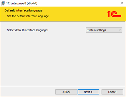 Fig. 21. Selecting interface language
You need to specify one of the interface languages as a default interface language.
After the installation procedure is completed, the conf.cfg file describing the default interface language will be created in the conf directory of the root directory.
To use 1C:Enterprise with a non-default interface language, specify the language at startup using the /L command-line parameter.
| Interface language | Language code |
|---|---|
| Azerbaijani | az |
| English | en |
| Armenian | hy |
| Bulgarian | bg |
| Hungarian | hu |
| Vietnamese | vi |
| Greek | el |
| Georgian | ka |
| Spanish | es |
| Italian | it |
| Kazakh | kk |
| Chinese | zh |
| Latvian | lv |
| Lithuanian | lt |
| German | de |
| Polish | pl |
| Portuguese (Brazil) | pt_BR |
| Romanian | ro |
| Russian | ru |
| Turkish | tr |
| Turkmen | tk |
| Ukrainian | uk |
| French | fr |
3.1.4.8. Installing 1C:Enterprise Server
If the 1C:Enterprise 8 server component is selected for installation, a wizard page will be available. On this page, you can select the 1C:Enterprise server installation mode and the user to run the server if it is installed as a Windows service.
If 1C:Enterprise is already installed as a Windows service on the computer, the installer will reinstall the service.
3.1.4.9. Installation Start
Click Install to start the installation procedure that:
-
Creates required folders
-
Copies files for selected components.
-
Creates configuration files.
-
Registers server software components.
-
Creates 1C:Enterprise startup shortcut on the desktop.
-
Starts 1C:Enterprise server if you install the server as a Windows service.
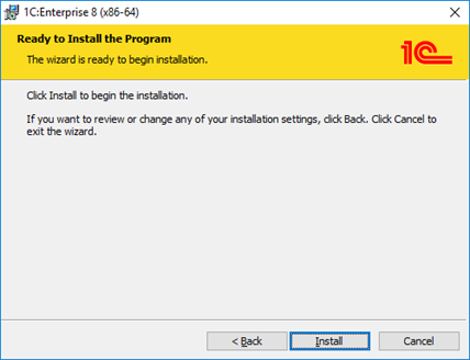 Fig. 22. Starting installation
In addition, a separate entry will be created for each version in the Install and delete programs component on Windows control panel. Entries must be of the following kind: 1C:Enterprise 8 (A.B.C.D).
3.1.4.10. Installing the Protection Driver
After the installation is completed, the installation wizard prompts you to install HASP Device Driver to protect you from unauthorized software use.
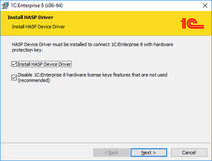 Fig. 23. Installing the protection driver
You have to install the driver if you have a dongle for plugging into a USB port of this computer and:
-
The user has a License Agreement to use 1C:Enterprise at one workplace.
-
The user has an additional License Agreement to use 1C:Enterprise at one additional workplace.
-
The user has a License Agreement to use 1C:Enterprise server.
When installing the protection driver, a web-based driver management interface is installed automatically. To minimize risks and increase safety for 1C:Enterprise servers and user workstations, it is recommended that you disable the web-based protection driver interface when installing the driver. To do this, select the Disable 1C:Enterprise 8 hardware license key features that are not used (recommended) check box.
3.1.4.11. Installation Completion
If the installation is successful, the final page of the installation wizard opens. On this page, you can decide whether to open a file with information recommended for reading before using this system version (to do it, select the Open Readme file check box). You can also install client application distribution packages to simplify the automated update of these applications on user computers.
To install client application distribution packages, select the following check box: Install thin client distribution packages for the automated update of clients via web server in the installation directory. The check box becomes available if the directory with the 1C:Enterprise installation files contains a file named according to one of the formats: win-mac-clients-distr_A.B.C.D.exe or all-clients-distr_A.B.C.D.exe.
The checkbox state is saved to the InstallComponents parameter of the 1cestart.cfg file (using the COPYTHINCLIENTDST key). Installation of the client application distribution package requires administrator rights.
 Fig. 24. Installation completion
Click Done to complete the installation. Further behavior (after closing the installer dialog box) depends on the check boxes selected on this page:
-
Show Readme opens the readme.htm file in the default interface language.
-
Store thin client distribution packages in the installation folder to update clients automatically… starts the installation of client application distribution packages.
-
Automated update of client applications.
-
1cestart.cfg configuration file.
3.1.4.12. Recommendations for Component Registration
The installer registers some components such as COM connection. The registration method depends on the installation mode.
-
Installation "for computer": the cluster console and COM connection (V83.COMConnector COM object) are registered "for computer".
-
Installation "for user": the cluster console and COM connection (V83.COMConnector COM object) are registered "for user".
1C:Enterprise version to which the COM connection is established (using V83.COMConnector) and 1C:Enterprise version from which the COM connection is generated must be identical or differ in the first two digits. In other words, 1C:Enterprise 8.3 can establish a COM connection with 1C:Enterprise 8.2, 8.1, and so on, but 1C:Enterprise 8.3.6 cannot establish a COM connection to 8.3.5. At the same time, 1C:Enterprise 8.3.6.2100 can a establish COM connection with 8.3.6.2100.
3.1.5. Typical 1C:Enterprise Installation Scenarios
3.1.5.1. On Linux
3.1.5.2. General Information
This section contains typical installation scenarios of 1C:Enterprise components on Linux broken down by different processors. Each installation scenario includes a list of components and packages to install. You will also find installation specifics to consider, if any.
Installation requires superuser (root) rights.
3.1.5.3. Installing a Production Server
- 1C:Enterprise installer
- Allow installation of the following components:
-
1C:Enterprise 8 server
-
1C:Enterprise server administration
-
Web server extension modules. Install this component if you intend to configure infobase access using a web server on a computer with a server cluster.
- Package manager
- Install the following packages:
-
common and, if required, the common-nls resources
-
server and, if required, the server-nls resources
-
ws and, if required, the ws-nls resources Install this package if you intend to configure infobase access using a web server on a computer with a server cluster.
- Result
- 1C:Enterprise server cluster components are installed. During the installation, an operating system user called usr1cv8 is created. 1C:Enterprise server processes will be executed under this account. Configure automatic server startup manually. For more information, see Run as a service.
3.1.5.4. Adding a Server to a Server Cluster
This scenario is used if you need to add another physical server to the existing server cluster (for example, to improve performance). For example, an extended server cluster is located on the COMP1 computer and you want to install an additional working server on the COMP2 computer. Then to add a working server, follow these steps:
-
Install the 1C:Enterprise server on COMP2.
-
Using the server console, connect to the server cluster (COMP1) to which you want to add the server (see Registering a working server instance).
-
Add a new production server (on COMP2) to the cluster located on COMP1 (see Adding production servers to a cluster).
-
If necessary, specify functionality assignment rules for the COMP2 production server.
After adding, delete the main cluster server registration from the computer which was added as an additional cluster server (COMP2).
You can perform cluster management operations using either the cluster console (runs on Windows only) or the administration server and utility (see Server cluster administration server).
3.1.5.5. Web Client
- 1C:Enterprise installer
- Allow installation of the following components:
-
1C:Enterprise 8 server
-
1C:Enterprise server administration
-
Web server extension modules.
- Package manager
- Install the following packages:
-
common and, if required, the common-nls resources
-
server and, if required, the server-nls resources
-
ws and, if required, the ws-nls resources
- Result
- Publish the web client using the utility of the webinst command-line.
3.1.5.6. On Windows
3.1.5.7. General Information
This section contains typical examples of 1C:Enterprise components installation on Windows.
For each installation option, a list of components to be installed and specific installation instructions (if any) are provided.
3.1.5.8. Cluster Core Server Installation
The installer copies required files to the computer and can configure startup of the main server agent as an application or as a Windows service. To install a server cluster select the following components: 1C:Enterprise server and 1C:Enterprise server administration.
If you install 1C:Enterprise server as a Windows service (recommended installation method), select a user and enter a password for them. By default, USER1CV8 is specified. The said user can be created upon initial installation of 1C:Enterprise server cluster. Make sure that the user specified to start the service is granted all access rights (see User rights). If the user is created by the installer, the access rights mentioned above are granted by default. If the password is empty, the installer will not be able to start the server. Moreover, the selected user is always granted all rights required to access the directory of server service files. The server cluster will be started during the installation. After installation completion, the cluster will be fully operational.
If you install a server as an application, you need to start the server cluster manually after installation completion.
3.1.5.9. Adding a Server to a Server Cluster
This scenario is used if you need to add another physical server to the existing server cluster (for example, to improve performance). For example, an extended server cluster is located on the COMP1 computer and you want to install an additional working server on the COMP2 computer. In this case, to add a working server, you need to do the following:
-
Install the 1C:Enterprise server on COMP2 (see Cluster core server installation).
-
Using the server console, connect to the server cluster (COMP1) to which you want to add the server (see Registering a working server instance).
-
Add a new production server (on COMP2) to the cluster located on COMP1 (see Adding production servers to a cluster).
-
If necessary, specify functionality assignment rules for the COMP2 production server.
After adding, delete the main cluster server registration from the computer which was added as an additional cluster server (COMP2).
You can perform cluster management operations using either the cluster console (you can find the links to it above) or the administration server and utility (see Server cluster administration server).
3.1.5.10. Data Accelerator Settings
There are two ways you can deploy Data Accelerator:
-
If a server cluster contains one working server, Data Accelerator will be started on this server by default. For such deployment, keep in mind that overall available RAM on a working server must be calculated considering information on memory consumption by 1C:Enterprise server cluster and Data accelerator memory requirements. In this case, the overall RAM of a working server must be greater than the sum of required memory values specified for the server cluster and Data Accelerator. For example, 1C:Enterprise server cluster uses 5 GB of memory in regular mode. If you add Data Accelerator to a server, the minimum memory amount for this server will be 69 GB and the recommended memory amount will be 520 GB.
-
If 1C:Enterprise server clusters function on several working servers, you can run several instances of the Data Accelerator. Each working server where the Data Accelerator will function must meet system requirements for the Data Accelerator. Data Accelerator services are placed on specific working servers based on functionality assignment rules. This process will be reviewed further in this section.
The number of Data Accelerator instances that operate in one server cluster depends on the license level:
-
PROF license. You can use one Data Accelerator instance.
-
CORP license. The number of Data Accelerator instances is not limited by the license.
Keep in mind that physical RAM is generated by standard memory modules and cannot be less than the value calculated for selected deployment option.
In addition to setting the required amount of RAM and functionality assignment rules, you need to configure some operating system settings on each working server where you are going to run the Data Accelerator instance:
-
On Windows: manually set up swap file size. The minimum swap file size cannot be less than the working server RAM. Recommended swap file size: 512 GB or more.
-
On Linux: change memory control strategy. To do this, set the vm.overcommit_memory system parameter to 1. The user who has a superuser password can do it using the following command: sudo sysctl -w vm.overcommit_memory=1.
If you use a configuration with several working servers, the Data Accelerator service is placed on a required working server according to functionality assignment rules. These rules can be conditionally divided into:
-
"Permitting" rules. They allow you to run a Data Accelerator instance on a working server.
-
"Prohibiting" rules. They prohibit to place a Data Accelerator instance on a working server. All functionality assignment rules for the Data Accelerator service that follow a prohibiting rule are ignored. If a prohibiting rule for the Data Accelerator service is the first rule in the list, it is considered that the Data Accelerator service is not running on this working server.
To place Data Accelerator instances, use the following algorithms:
-
The number of permitting rules is no more than 1. It does not depend on the license level:
-
All working servers for which there is at least one functionality assignment rule for the Data Accelerator are calculated. Parameters of functionality assignment rules are ignored.
-
If there are no permitting rules in the list, it is considered that a Data Accelerator instance can be run on any working server where the prohibiting rule is not applied.
-
An arbitrary working server is selected from the resulting list.
-
A Data Accelerator instance is run on the selected working server.
-
-
The number of permitting rules is more than 1. A CORP license is required:
-
If there are no permitting functionality assignment rules in the server cluster, one Data Accelerator instance will be placed according to the above algorithm (the number of permitting rules is no more than 1).
-
If there is at least one permitting functionality assignment rule in the server cluster, the list of working servers for which permitting rules are configured is generated. Parameters of functionality assignment rules are ignored.
-
On each working server from the generated list, a Data Accelerator instance is started.
-
-
The list of working servers where the Data Accelerator service functions can change after applying new functionality assignment rules.
Examples of functionality assignment rules performing different functions are provided below:
-
Permitting rule. You need to specify such a rule for each working server where you are going to use the Data Accelerator.
-
Assignment rule object: Data Accelerator service.
-
Rule type: Assign.
-
Infobase name: not specified.
-
Additional parameter value: can be not specified (in this example, the parameter is not considered).
-
-
If you need only the Data Accelerator service to run and other cluster services not to run on the selected working server, in addition to the permitting rule, specify the following rule for each working server:
-
Assignment rule object: Any assignment rule object.
-
Rule type: Do not assign.
-
Infobase name: not specified.
-
Additional parameter value: not specified.
-
-
Prohibiting rule:
-
Assignment rule object: Data Accelerator service.
-
Rule type: Do not assign.
-
Infobase name: not specified.
-
Additional parameter value: not specified.
-
-
Database copies functionality.
-
Data Accelerator system requirements.
-
Application of the requirements related to functionality assignment.
3.1.6. Installing and Configuring Additional Software
3.1.6.1. On Windows
3.1.6.2. Creating a Server Service Name for Kerberos Authentication
Windows authentication includes two authentication protocols: NTLM and Kerberos. When you build systems with transparent authentication (Single Sign-On, SSO), use the Kerberos protocol. This protocol supports delegation that allows you to safely pass authorization data to other collaboration participants (services) to perform operations on behalf of the client.
If the web server with the published infobase and 1C:Enterprise server cluster are located on different computers or 1C:Enterprise server cluster contains several servers, then Windows authentication can run only over Kerberos.
Server service name (Service Principal Name, SPN) is a service instance UUID. SPNs are used upon Kerberos authentication to link a service instance to the account used to log in to the service. It allows the client application to request account authentication from the service even if the client does not have an account name.
Creating a server service name is recommended for correct operation of Kerberos authentication and required to configure limited Kerberos delegation. When created, the server service name is associated with the domain account that starts 1C:Enterprise server service.
Specify a server service name for each working server included in 1C:Enterprise server cluster. The most common SPN format is <service class>/<host name> (host-based services). Note that there are common service class names, such as http, host, termsrv, and so on. We do not recommend that you use them as the service name for 1C:Enterprise server cluster. We recommend that you use a name that will be associated with 1C:Enterprise and will probably not be used by any other manufacturer or software. For example, you can use the following names as this service class: srv1c or svc1c.
So, the server service name for a server cluster running on the myserver.mydomain computer may look as follows: srv1c/myserver.mydomain or svc1c/myserver.mydomain.
To specify a server service name for a server cluster, follow these steps:
- Register a server service name on a domain controller using the setspn command:
setspn -S srv1c/myserver.mydomain mydomain\svc-1cIn this command line:
-
srv1c/myserver.mydomain is a server service name.
-
domain1\svc-1c is a domain account name of a user running 1C:Enterprise server cluster.
You can get a list of server service names registered for an account using the following command on the computer that serves as a domain controller:
setspn -L mydomain\svc-1c- Specify the 1C:Enterprise server service name (SPN) property value for the working server. In the example above, the computer is myserver and the server service name is srv1c/myserver.mydomain.
If 1C:Enterprise server cluster service runs on behalf of the local system account (Local System), you can use a registered service name in the following format: HOST/server_name. However, we do not recommend that you use this name.
- In the domain controller settings, in the properties of the computer running the web server, or in the account properties of the user running the web server, enable full or limited delegation for SPN srv1c/myserver.mydomain.
-
Service Principal Name (SPN) (https://docs.microsoft.com/windows/win32/ad/service-principal-names).
-
Properties of a production server (see Adding production servers to a cluster).
3.1.6.3. On Linux
3.1.6.4. Configuring Kerberos Authentication
This section describes how to configure Kerberos authentication of 1C:Enterprise server for a basic system that consists of three computers: domain controller, main server of 1C:Enterprise cluster, and workstation.
3.1.6.5. Base System Description
The base system contains the following computers:
-
Active Directory domain controller:
-
Hostname: main.
-
IP address: 192.168.29.150.
-
Domain name: krb.local.
-
-
Main server of 1C:Enterprise cluster:
-
Operating system: Fedora 7.
-
Hostname: srv1c.
-
IP address: 192.168.29.151.
-
MIT Kerberos implementation is installed (the krb5-workstation package).
-
-
Workstation.
3.1.6.6. Setting Up a Domain Controller
This section assumes that the Active Directory domain controller is configured and running. Based on this, to configure Kerberos authentication, you need to perform the following steps:
-
In the DNS server, you must manually register all Linux computers. Windows computers are registered automatically when they are included in the domain. In our case, you need to manually register the main server of 1C:Enterprise cluster (since it runs the Linux version of the server) and include the workstation in the domain (it will be registered automatically).
-
After that, create a domain user account with which authorization requests to 1C:Enterprise server will be associated. In our example, this will be user usr1cv8 with password pass1cv8. In the properties of this account, clear the Use DES encryption types with this account check box. If your Kerberos implementation does not support the RC4-HMAC encryption algorithm, select the check box.
-
After that, generate a file with a secret key for the usr1cv8 domain user. To do this, use the ktpass utility included in the Windows Support Tools package. You can find it in the SUPPORT subdirectory of the Microsoft Windows installation disk.
Start the ktpass utility in the command line. For our example, the command line must look as follows:
C:\>ktpass -princ usr1cv8/srv1c.krb.local@KRB.LOCAL -mapuser usr1cv8 -pass pass1cv8 -out usr1cv8.keytab
C:\>
If the RC4-HMAC algorithm is not supported, the command line must look as follows:
C:\>ktpass -crypto DES-CBC-CRC -princ usr1cv8/srv1c.krb.local@KRB.LOCAL -mapuser usr1cv8 -pass pass1cv8 -out usr1cv8.keytab
C:\>
As a result, the usr1cv8.keytab file will be created in the current directory (C: drive root in the example) and the usr1cv8/srv1c.krb.local server service name will be associated with the usr1cv8 user. Use the server service name to configure limited delegation in a Windows domain.
In the pass parameter, the pass1cv8 password of the usr1cv8 domain user account is passed.
The out parameter specifies the name of the file with the key. In our case, this is usr1cv8.keytab. If 1C:Enterprise 8.3 server cluster is running on behalf of another user, for example usr1cv82, specify usr1cv82.keytab as the name of the key file.
3.1.6.7. Configuring the Main Server of 1C:Enterprise Cluster
In this section, it is assumed that 1C:Enterprise server cluster is already installed and running on a main server of the cluster.
First of all, you need to specify the DNS server for the main server of the cluster. It must be a DNS domain controller.
As a result, the file must contain the following lines:
nameServer 192.168.29.150
search krb.local
After that, check DNS operation. To do this, run the ping command:
srv1c:~#ping main -c 1
PING main.krb.local (192.168.29.150)56(84)bytesofdata.
64 bytes from 192.168.29.150: icmp_seq=1 ttl=128 time=0.177 ms
--- main.krb.localpingstatistics ---
1 packets transmitted, 1 received, 0% packet loss, time 0ms
rtt min/avg/max/mdev = 0.177/0.177/0.177/0.000 ms
srv1c:~#Therefore, you need to synchronize time between the main server of the cluster and domain controller. To do this, use the ntpdate command:
srv1c:~#ntpdate main
4 Jun 11:51:53 ntpdate[2527]: step time Server 192.168.29.150 offset -56.766439 sec
srv1c:~#
Now you need to configure Kerberos. To do this, edit the /etc/krb5.conf file. In this case, we need the NETBIOS name of the domain controller. It is usually an uppercase domain name. Therefore, in our case, the NETBIOS name will be KRB.LOCAL. As a result, the /etc/krb5.conf file must look as follows:
srv1c:~#cat/etc/krb5.conf
[logging]
Default = FILE:/var/log/krb5libs.log
Kdc = FILE:/var/log/krb5kdc.log
admin_Server = FILE:/var/log/kadmind.log
[libdefaults]
default_realm = KRB.LOCAL
dns_lookup_realm = false
dns_lookup_kdc = false
default_tkt_enctypes = rc4-hmac
default_tgs_enctypes = rc4-hmac
[realms]
KRB.LOCAL = {
  kdc=main.krb.local:88
  default_domain=krb.local
}
[domain_realm]
krb.local = KRB.LOCAL
.krb.local = KRB.LOCAL
KRB.LOCAL = KRB.LOCAL
.KRB.LOCAL = KRB.LOCAL
[kdc]
Profile = /var/kerberos/krb5kdc/kdc.conf
[appdefaults]
Pam = {
  Debug = true
  ticket_lifetime = 36000
  renew_lifetime = 36000
  forwardable = false
  krb4_convert = false
}
srv1c:~#
If the RC4-HMAC algorithm is not supported, the default_tkt_enctypes and default_tgs_enctypes parameters must look as follows:
...
default_tkt_enctypes = des-cbc-crc des-cbc-md5
default_tgs_enctypes = des-cbc-crc des-cbc-md5
...
Now you need to check authentication system operation. To do this, execute the kinit <name> command, where name is the name of an arbitrary user registered in the krb.local domain. In the example, this will be the user name. Then, specify the password of this user and press Enter. If the program does not display any messages after that, you have done everything correctly.
You can verify this with the klist command. As you can see, we received a so-called ticket-granting ticket from the Key Distribution Center. This function is performed by the domain controller. After that, use the kdestroy command to clear the local ticket cache to return to its original state.
srv1c:~#kinit user
Password for user@KRB.LOCAL:
srv1c:~#klist
Ticket cache: FILE:/tmp/krb5cc_0
Default principal: user@KRB.LOCAL
Valid starting Expires Service principal
06/04/08 11:29:21 06/04/08 21:28:28 krbtgt/KRB.LOCAL@KRB.LOCAL
renew until 06/05/08 11:29:21
Kerberos 4 ticket cache: /tmp/tkt0
Klist : You have no tickets cached
srv1c:~#kdestroy
srv1c:~#
After that, send the usr1cv8.keytab file with the secret key obtained during domain controller setup to the main server of 1C:Enterprise cluster. Copy this file to the directory where 1C:Enterprise server is installed (by default it is /opt/1cv8/i386/A.B.C.D or /opt/1cv8/x86_64/A.B.C.D for the 64-bit version), and set the rights and owner of the file as below:
srv1c:~#cd /opt/1cv8/i386/A.B.C.D
srv1c:i386#chown usr1cv8:grp1cv8 usr1cv8.keytab
srv1c:i386#chmod 600 usr1cv8.keytab
srv1c:i386#
To place the file with a secret key somewhere else, change the SRV1CV8_KEYTAB variable in the configuration file to specify the new file location.
After that, using the klist command, you must verify that all settings are correct. To do this, execute the following command:
srv1c:~#klist -e -k -t /opt/1cv8/i386/A.B.C.D/usr1cv8.keytabFor the example used, the command result must look as follows:
Keytab name: FILE: /opt/1cv8/i386/A.B.C.D/usr1cv8.keytab
KVNO Principal
---- -------------------------------------------------------------
13 usr1cv8/srv1c.krb.local@KRB.LOCAL (ArcFour with HMAC/md5)
If the RC4-HMAC algorithm is not supported, the command execution result will look as follows:
Keytab name:FILE: /opt/1cv8/i386/A.B.C.D/usr1cv8.keytab
KVNO Principal
---- -------------------------------------------------------------
13 usr1cv8/srv1c.krb.local@KRB.LOCAL (DES cbc mode with RSA-MD5)
As you can see, the file with the secret key contains exactly what we need: the Principal column indicates the service name that we specified when creating the file with the secret key and the correct encryption algorithm (ArcFour with HMAC/md5 for RC4-HMAC or DES cbc mode with RSA-MD5 for DES).
Next, you need to check whether Kerberos can work without a password using a secret key. Use the kinit command to specify that you need to use authentication information from the file (/opt/1cv8/i386/A.B.C.D/usr1cv8.keytab or /opt/1cv8/x86_64/A.B.C.D /usr1cv8.keytab for 64-bit version) and read the key for the usr1cv8/srv1c.krb.local@KRB.LOCAL service from there. As a result, kinit must run without any messages, not ask for any passwords, and return control to the command line:
srv1c:~#kinit -k -t /opt/1cv8/i386/A.B.C.D/usr1cv8.keytab usr1cv8/srv1c.krb.local@KRB.LOCAL
srv1c:~#
Use the klist command to review the results of previous operations. If they have been successful, you will see information that looks approximately as follows:
srv1c:~#klist
Ticket cache: FILE:/tmp/krb5cc_0
Default principal: usr1cv8/srv1c.krb.local@KRB.LOCAL
Valid starting Expires Service principal
06/04/08 11:44:54 06/04/08 21:43:58 krbtgt/KRB.LOCAL@KRB.LOCAL
renew until 06/05/08 11:44:54
Kerberos 4 ticket cache: /tmp/tkt0
klist: You have no tickets cached
srv1c:~#
If any settings are incorrect, this command will display:
srv1c:~#klist
klist: No credential scache found (ticket cache FILE:/tmp/krb5cc_1000)
Kerberos 4 ticket cache: /tmp/tkt1000
klist: You have no tickets cached
srv1c:~#
If the health check is successful, starting from this moment, 1C:Enterprise cluster server can process authentication requests. In this case, server restart is not required unless location of the file with the secret key has been changed in the configuration file.
3.2. Installing Database Servers
3.2.1. General Information
You can use the following objects as a 1C:Enterprise database server:
-
IBM DB2 (for Windows and Linux)
-
Microsoft SQL Server (only for Windows)
-
Oracle Database (for Windows and Linux)
-
PostgreSQL (for Windows and Linux)
3.2.2. Installing IBM Db2
Database servers are installed from IBM DB2 distribution packages.
IBM DB2 versions supported by 1C:Enterprise are published at: http://v8.1c.ru/requirements/.
To facilitate setup of IBM DB2 for operation with 1C:Enterprise platform, IBM DB2 introduced the 1C value for the DB2_WORKLOAD group registry variable.
If you specify DB2_WORKLOAD = 1C, IBM DB2 automatically configures all required registry variable values to optimize DB2 operations with 1C:Enterprise platform.
Registry variable value is set using the following command:
db2set DB2_WORKLOAD=1CAfter setting the 1C value for the DB2_WORKLOAD group registry variable, you must restart the database server.
To find out which registry variable values will be used when setting the value of DB2_WORKLOAD = 1C, you can use the following command:
db2set -gd DB2_WORKLOAD=1CThis command will display a list of IBM DB2 registry variables and their values corresponding to the DB2_WORKLOAD = 1C group registry variable.
If 1C:Enterprise server is running as a service, follow these steps:
-
Include the user running 1C:Enterprise server (USR1CV8 by default) in the DB2ADMNS group.
-
For the DB2 copy in use, set the SYSADM_GROUP parameter to DB2ADMNS.
Installation information is available in the server documentation:
-
IBM Db2 v9.7: http://publib.boulder.ibm.com/infocenter/db2luw/v9r7/topic/com.ibm.db2.luw.qb.server.doc/doc/r0025127.html.
-
IBM Db2 v10.1: http://publib.boulder.ibm.com/infocenter/db2luw/v10r1/topic/com.ibm.db2.luw.qb.server.doc/doc/r0025127.html.
-
IBM Db2 v11.1: http://www.ibm.com/support/knowledgecenter/SSEPGG_11.1.0/com.ibm.db2.luw.qb.server.doc/doc/r0025127.html.
3.2.3. Installing Microsoft SQL Server
The database server is installed from Microsoft SQL Server distribution media.
The user on whose behalf 1C:Enterprise server accesses MS SQL Server must have the processadmin or sysadmin fixed server role.
Installation information is available in the server documentation:
-
Microsoft SQL Server 2005: http://msdn.Microsoft.com/ru-ru/library/ms143516(SQL.90).aspx.
-
Microsoft SQL Server 2008: http://msdn.Microsoft.com/ru-ru/library/bb500469(v=sql.100).aspx.
-
Microsoft SQL Server 2008 R2: http://msdn.Microsoft.com/ru-ru/library/bb500469(v=sql.105).aspx.
-
Microsoft SQL Server 2012: http://msdn.microsoft.com/ru-ru/library/bb500469(v=sql.110).aspx.
-
Microsoft SQL Server 2014: http://msdn.Microsoft.com/ru-ru/library/bb500469(v=sql.120).aspx.
-
Microsoft SQL Server 2016: http://msdn.microsoft.com/ru-ru/library/bb500469(v=sql.130).aspx.
-
Microsoft SQL Server 2017: https://docs.microsoft.com/ru-ru/sql/database-engine/install-windows/install-sql-server?view=sql-server-2017.
-
Microsoft SQL Server 2019: https://docs.microsoft.com/ru-ru/sql/database-engine/install-windows/install-sql-server?view=sql-server-ver15.
-
MicrosoftSQLServer2022: https://learn.microsoft.com/ru-ru/sql/database-engine/install-windows/install-sql-server?view=sql-server-ver16.
3.2.4. Installing Oracle Database
The database server is installed from Oracle Database distribution packages.
Oracle Database versions supported by 1C:Enterprise are published at: http://v8.1c.ru/requirements/.
Installation information is available in the server documentation:
-
Oracle Database 10g Release 2: http://download.oracle.com/docs/cd/B19306_01/em.102/b16227/toc.htm (in English).
-
Oracle Database 11g Release 1: http://download.oracle.com/docs/cd/B28359_01/em.111/b31207/toc.htm (in English).
-
Oracle Database 11g Release 2: http://docs.oracle.com/cd/E11882_01/em.112/e12255/toc.htm (in English).
-
Oracle Database 12c Release 1: http://docs.oracle.com/database/121/nav/portal_11.htm.
The database server in terms of 1C:Enterprise corresponds to the concept of DATABASE in terms of Oracle Database. Database in 1C:Enterprise corresponds to data schema in Oracle Database. When you create an infobase in 1C:Enterprise, an infobase user and their data schema are created in Oracle Database.
1C:Enterprise 8 uses the following tablespaces in Oracle Database operations:
-
For data: v81c_data.
-
For indexes: V81C_INDEX.
-
For LOB: V81C_LOB.
-
For temporary files: V81C_TEMP.
If tablespaces with such names exist, they will be used. If not, they will be created along with an infobase and datafiles will have default paths.
The V81_INDEX_BIG tablespace is used for index operations. It is created when index creation resulted in error ORA-01450. If this tablespace already exists, it will be used.
When you create a DATABASE, set the CHARACTER SET parameter to AL32UTF8 for this DATABASE.
Before using the Oracle Database server with 1C:Enterprise, you need to configure multilingual collation for the database server. To do this, follow these steps:
-
Copy the lx327c6.nlt file from the Additional\OracleDatabase directory of 1C:Enterprise distribution package to an empty directory on the hard drive of the computer where Oracle Database is installed.
-
Run Oracle Locale Builder (lbuilder).
-
Start generation of NLB files (Tools – Generate NLB) by specifying the folder with the lx327c6.nlt file.
-
Stop all Oracle Database services running from the Oracle Database home directory (ORACLE_HOME).
-
Create a backup of the lx0boot.nlb and lx1boot.nlb files from the ORACLE_HOME/nls/data folder.
-
Copy the lx1boot.nlb and lx327c6.nlb files from the folder where they were created by the Oracle Locale Builder utility to ORACLE_HOME/nls/data. While copying, agree to overwrite the lx1boot.nlb file.
-
Start Oracle Database services.
3.2.5. Install PostgreSQL
3.2.5.1. General Information
The database server is installed from 1C:Enterprise distribution media. PostgreSQL DBMS is supported both on Windows and Linux.
When you initialize a database cluster, specify UTF-8 encoding.
1C:Enterprise 8 supports the following tablespaces for PostrgeSQL operations:
-
For data: v81c_data.
-
For indexes: v81c_index.
If the table space with such names exist, they will be used. If not, we recommend that you create them:
create tablespace v81c_index location <Folder name>;
create tablespace v81c_data location <Folder name>;
Where <Folder name> is a full path to the directory where files of the created tablespace will be stored. If the tablespaces do not exist, a tablespace with name pg_default will be used.
To work with 1C:Enterprise, a modified version of PostgreSQL is required. You can get this version on the ITS disk or at: https://releases.1c.ru/project/AddCompPostgre (requires IT-support section access).
1C:Enterprise can work with a cluster created using the following PostgreSQL DBMS versions:
-
PostgreSQL 8.1.5-X.1C – 9.1.2-1.1C;
-
PostgreSQL 9.2.1-2.1C
-
Standard PostgreSQL version if regional (locale) settings of the cluster and the infobase are identical
1C:Enterprise operation with a cluster created by the standard PostgreSQL version is allowed only using the PostgreSQL distribution package released by 1C.
You can switch to an earlier or later version of 1C:Enterprise without having to change PostgreSQL version or perform other actions.
Infobases created using PostgreSQL 9.2.1-2.1C or later cannot be used with the earlier versions of 1C:Enterprise (8.3.2 or earlier). Do not create infobases using PostgreSQL version 9.2.1-2.1 C, if you expect to access these infobases from earlier 1C:Enterprise versions.
3.2.5.2. Installing PostgreSQL for Windows
To install the version you need:
-
Unpack the ZIP archive with the PostgreSQL distribution package.
-
Run the postgresql-<Version>-1.1C.msi file, where \<Version> is PostgreSQL version to be installed.
-
Follow installer instructions.
3.2.5.3. Installing PostgreSQL for Linux
The distribution package of the modified PostgreSQL version consists of 11 packages. You must install them in the following order:
-
postgresql-libs-8.3.<X>-<Y>.1C.i386.rpm,
-
postgresql-8.3.<X>-<Y>.1C.i386.rpm,
-
postgresql-Server-8.3.<X>-<Y>.1C.i386.rpm,
-
postgresql-contrib-8.3.<X>-<Y>.1C.i386.rpm.
Where <X> and <Y> are corresponding positions in the PostgreSQL version.
After that, the postgres user will appear in the system and the /etc/init.d/postgresql script will be created to start and stop the DBMS.
Next, you need to set the desired value of the LANG variable and run /etc/init.d/postgresql for initial database creation. This can be done with the command:
LANG=ru_RU.utf-8 /etc/init.d/postgresql startThis will create a database located in the /var/lib/pgsql/data directory. All the above actions require superuser (root) rights.
Chapter 4. Running System Components
4.1. General Information
When you install 1C:Enterprise, the following structure is created in the Start – Programs menu (see example for Windows 10):
1C:Enterprise
1C:Enterprise 8 (folder)
  1C:Enterprise (A.B.C.D)
  ReadMe – Additional information
  Register server administration utility (A.B.C.D)
  1C:Enterprise server administration
  Start server (A.B.C.D)
  Install protection driver
  Remove protection driver
In the above list:
| Item | Purpose |
|---|---|
| Install protection driver | Starts installation of the protection driver. |
| Remove protection driver | Starts removal of the protection driver. |
| ReadMe – Additional Information | Additional information not included in the documentation. |
| 1C:Enterprise server administration | Server cluster administration utility (if any 1C:Enterprise server cluster access components are installed). |
| Start server (A.B.C.D) | Starts 1C:Enterprise server as a service (if the Install 1C:Enterprise 8 server as Windows service check box was selected during server installation) or as an application (if the Install 1C:Enterprise 8 server as Windows service check box was cleared during server installation). In this case, server shutdown is identical to closing a regular application. |
| Register server administration utility (A.B.C.D) | Registers the 1C:Enterprise server administration utility (radmin.dll) for a specific version, so that you can connect to the servers of this version using the administration utility. |
In this table:
-
Specifying the name of an application without specifying a version means the application or file from the version that was installed latest.
-
Specifying (A.B.C.D) next to an application name means that a separate menu item is created for each installed version, where A.B.C.D means the full number of the installed version. For example, if two versions are installed – 8.3.12.100 and 8.3.12 150, there will be two options in the menu: Start the server (8.3.12.100) and Start the server(8.3.12.150).
-
If the 64-bit version of 1C:Enterprise is installed, x86-64 will be included in the folder name and names of items in this folder.
When starting 1C:Enterprise server components, the system command-line interface is actively used.
If 1C:Enterprise server is installed in "For user" mode, it cannot be started as a Windows service.
4.2. Running the Server Agent
4.2.1. General Information
To start 1C:Enterprise server cluster, you must start the server agent (ragent). All further actions will be executed by the system automatically. At startup, the server agent searches for a list of clusters registered on this computer.
If the cluster list is found, the server agent starts specified cluster managers. Through these, it obtains information about the working processes that must be run in each cluster and starts these processes, with or without the help of agents of other working servers of the cluster.
If no list of clusters is found, the server agent creates a default cluster. Default cluster specifications:
-
Network port number: 1541.
-
Network port range: 1560:1591.
-
Port number used by the debug server in debug mode over HTTP: 1550.
-
One working process is used: port number is selected from the specified range.
4.2.2. On Linux
4.2.2.1. General Information
The installer sets up server processes so that they are started in daemon mode, that is, without binding them to any specific control terminal. If necessary, the server agent can be started with command-line switches.
Depending on a used processor architecture, you can use various subsystems of operating system service management for managing 1C:Enterprise server cluster start:
-
x86/x86-64 architecture, ARM64. The systemd subsystem. To operate with systemd, use the systemctl utility. The files that you use to configure systemd are called units or service files.
-
E2K architecture. The init subsystem. init tools depend on the used Linux distribution package and package format.
If you need to configure the systems so that the server cluster starts immediately, then configure the corresponding service management subsystem of the Linux operating system accordingly. To operate with the service management subsystem, you need the superuser rights (root). In the examples, this point is ignored (to shorten the example). So you will either need to run the console as superuser or precede each service management subsystem command with a sudo command. For example: sudo systemctl list (gets a list of running services) or sudo chkconfig --add <UniqueScriptName> (adds a server cluster startup script to the start script of the system for RPM distribution packages).
4.2.2.2. Run as an Application
You can start the server agent as an application. In the simplest version, the startup command will look as follows:
/opt/1cv8/x86_64/8.3.27.100/ragent /d "~/cluster data" /debug -HTTPIn this example, the server agent is started with the following parameters:
-
1C:Enterprise version: 8.3.27.100, 64-bit version.
-
Directory with service files of the server cluster: ~/cluster data.
-
The server cluster is running in debug mode (/debug) over the HTTP protocol (/debug HTTP).
-
Command line for starting the server agent (ragent).
-
Configuration setup file of debug server users.
4.2.2.3. Run as a Service
4.2.2.4. Systemd Subsystem
To use 1C:Enterprise server as a service and automatically start it at operating system startup, register the server cluster unit in systemd:
- On Linux (except for CentOS 7), run the following command:
systemctl link /opt/1cv8/arch/A.B.C.D/srv1cv8-A.B.C.D@.serviceTo register, specify the full path to the systemd unit.
-
For CentOS 7:
- Create a hard link or a copy of the srv1cv8-A.B.C.D@.service file named srv1cv8-A.B.C.D@default.service:
ln /opt/1cv8/arch/A.B.C.D/srv1cv8-A.B.C.D@{,default}.service- Register the unit:
systemctl link /opt/1cv8/arch/A.B.C.D/srv1cv8-A.B.C.D@default.serviceIn the above command examples, replace arch with the bitness of the used 1C:Enterprise version:
-
32-bit version: i386.
-
64-bit version: x86_64.
Use the unit available in the 1C:Enterprise distribution package to register an instance of the server cluster service named default. If you need to organize simultaneous operation of several server cluster instances on one computer, set up an application. These settings depend on which platform versions are used for different cluster instances:
-
One version for different instances: see One 1C:Enterprise version for different cluster instances.
-
Different versions for different instances: see Different 1C:Enterprise versions for different cluster instances.
After you complete the previous steps, the start of a server cluster of a specific version and bitness will be added to the list of automatically started services.
After registration, you can configure the automatic startup of the required service instance when starting the operating system, as well as manage a specific service instance:
| Action | Command |
|---|---|
| Enable automatic start | systemctl enable srv1cv8-A.B.C.D@instName |
| Disable automatic start | systemctl disable srv1cv8-A.B.C.D@instName |
| Start | systemctl start srv1cv8-A.B.C.D@instName |
| Stop | systemctl stop srv1cv8-A.B.C.D@instName |
| Get status | systemctl status srv1cv8-A.B.C.D@instName |
The table uses a unique service name: srv1cv8-A.B.C.D@instName, where instName is a name of the specific instance. An instance that is registered with default parameters has the following name defined: default.
4.2.2.5. Init Subsystem
To automatically start 1C:Enterprise server at the operating system startup:
-
Copy the srv1cv83 file from the directory of the required version to the /etc/init.d directory.
-
Rename the copied file so that the script name within the /etc/init.d directory is unique (hereinafter used as <UniqueScriptName>). You can specify a full number of the starting server version in the startup script name. For example, the startup script for version 8.3.22.100 will be named srv8-3-22-100.
-
Copy the srv1cv83.conf configuration file from the directory of the required version to the following directory:
-
For RPM systems: /etc/sysconfig.
-
For DEB systems: /etc/default.
-
-
Do the following for the copied configuration file in the destination directory:
-
Delete the file extension.
-
Rename the file so that it matches the start script name (created at step 2). The renamed configuration file will contain startup parameters for the server of the same name as the configuration file. For the example from step 2, the configuration file must be called srv8-3-22-100.
-
-
Add the server startup script to the system startup script:
- For RPM systems:
chkconfig --add <UniqueScriptName>
chkconfig <UniqueScriptName> on- For DEB systems:
update-rc.d <UniqueScriptName> defaults
service <UniqueScriptName> start
In the mentioned commands, <UniqueScriptName> is a start script (and configuration file) name selected when coping the srv1cv83 file to the /etc/init.d directory. In the example from step 2, replace <UniqueScriptName> with srv8-3-22-100.
As a result, the start of a server of a specific version and bitness will be added to the list of automatically started services.
4.2.2.6. Init Subsystem: Operation Management Script
To manage 1C:Enterprise server cluster, use the script created based on the srv1cv83 script that is located in the directory of a specific version. You can create a script for managing a specific version by copying or creating a symbolic link. Such script is located in the /etc/init.d directory and must have a unique name (for details, see p. 2 of the previous section). You cannot run a script from a specific version directory directly from this directory. However, all scripts created based on the srv1cv83 script will have the same command line:
script-from-srv1cv83 start|stop|restart|info|statusScript commands:
| Command | Description |
|---|---|
| info | Displays information about server settings: ports specified at startup, cluster directory, configuration debug mode status, connection security level. |
| restart | Restarts the server. Equal to the sequence of the stop and start commands. |
| start | Starts the server. The script allows you to launch one instance of the 1C:Enterprise server, which is specified during setup. |
| status | Displays information about the server status (whether it is started/not started, and if it is started, whether it is currently running). |
| stop | Stops the server. Only the server that was previously launched by this script will stop operations. See the start command. |
4.2.2.7. Editing Server Cluster Instance Parameters
4.2.2.8. Systemd Subsystem
To edit any server cluster instance parameters, use the following command:
systemctl edit srv1cv8-A.B.C.D@instanceNameThen, in the opened file, create the [Service] section (if it is not set yet) and specify the parameters to be changed in it in the following notation: Environment=SRV1CV8_REGPORT=1541. In this example:
-
Environment. A required value. Defined by the systemd unit description syntax.
-
SRV1CV8_REGPORT. A server cluster parameter name. For the list of parameters, see the table below.
-
1541. A parameter value. Depends on the parameter name.
4.2.2.9. Init Subsystem
To edit the parameters of a server cluster instance, open the configuration file of the corresponding server cluster instance using any available editor. The configuration file name matches the file with the startup script name. The configuration file must be without an extension.
The location of the configuration file depends on the operating system version you are using:
-
For RPM systems: /etc/sysconfig.
-
For DEB systems: /etc/default.
4.2.2.10. Configuration File Parameters
The table lists parameters available for editing:
| Parameter | Description |
|---|---|
| SRV1CV8_DATA | Full path to the directory containing the server cluster service files (including the cluster list and the cluster infobase list). Default value: /home/usr1cv8/.1cv8/1C/1cv8. |
| SRV1CV8_DEBUG | Indicates that the server cluster is started in debug mode. The
parameter can take values:
|
| SRV1CV8_KEYTAB | Path to the keytab file that will be used by 1C:Enterprise server cluster to authenticate the operating system. Default value: /opt/1cv8/x86_64/A.B.C.D/usr1cv8.keytab. |
| SRV1CV8_PINGPERIOD | Connection interruption check frequency (in milliseconds). For more information, see 2.2.5.6. Connection Break Monitoring. You can change the value using the cluster administration tools. If at least one of the Verification period or Verification timeout parameters in the cluster settings is different from 0, these values will be used. Otherwise, the server cluster startup command-line options will be used. Default value: 1,000. |
| SRV1CV8_PINGTIMEOUT | Check timeout of the connection break monitoring system (in milliseconds). For more information, see Connection break monitoring. You can change the value using the cluster administration tools. If at least one of the Verification period or Verification timeout parameters in the cluster settings is different from 0, these values will be used. Otherwise, the server cluster startup command-line options will be used. Default value: 5,000. |
| SRV1CV8_PORT | Network port number of the server agent (ragent). For more information, see Client application and server cluster interaction. Default value: 1540. |
| SRV1CV8_RANGE | Network port ranges for dynamic selection. For more information, see 2.2.2. Client Application and Server Cluster Interaction. Default value: 1561:1590. |
| SRV1CV8_REGPORT | Network port number of the main cluster manager (rmngr). For more information, see Client application and server cluster interaction. Default value: 1541. |
| SRV1CV8_SECLEV | Connection security level. For more information, see Security
of data exchanged between a client and a server cluster. The
parameter can take values:
|
4.2.3. On Windows
4.2.3.1. Run as an Application
You can start the server agent as an application. In the simplest version, the startup command will look as follows:
"C:\Program Files\1cv8\8.3.27.100\bin\ragent.exe" /d "D:\Working directory\1C srvinfo\" /debug -HTTPIn this example, the server agent is started with the following parameters:
-
1C:Enterprise version: 8.3.27.100. The bitness depends on the operating system used.
-
Directory with service files of the server cluster: D:\Working directory\1C srvinfo\.
-
The server cluster is running in debug mode (/debug) over the HTTP protocol (/debug HTTP).
-
Command line for starting the server agent (ragent).
-
Configuration setup file of debug server users.
4.2.3.2. Run as a Service
If during server cluster installation the option of starting the main server agent as a service was selected, this service will be started automatically during the installation process and upon operating system startup.
If the main server agent was installed as an application, you can register the service manually and then start it.
The service name differs in 32- and 64-bit versions of 1C:Enterprise:
| 1C:Enterprise version | Service name |
|---|---|
| 32-bit version | 1C:Enterprise 8.3 Server Agent |
| 64-bit version | 1C:Enterprise 8.3 Server Agent (x86-64) |
In the simplest version, the service registration command line looks as follows:
C:\Program Files\1cv8\8.3.27.100\bin\ragent /srvc /agent /d "D:\Working directory\1C srvinfo\"The default service is started automatically when you turn on the computer. You can also manually start the service from Windows: My computer – Manage – Computer Management – Services and Applications – Services - 1C:Enterprise 8 Server Agent. You can also manually stop the service from Windows.
To unregister the service, execute this command:
ragent /rmsrvcTo simplify the registration and unregistration of the server cluster service, you can use batch files. See Auxiliary tools for examples.
-
Command line for starting the server agent (ragent).
-
Configuration setup file of debug server users.
4.3. Collaboration Between Server Processes
4.3.1. General Information
In most cases, one server agent runs per working server.
When multiple created clusters are controlled by a single server agent, the server agent ensures that their network ports do not conflict. If created clusters are controlled by different server agents, you need to ensure that there are no conflicts between the network ports of cluster managers.
You must always ensure that there are no conflicts among network port ranges of working processes on the server (if the server is used in different clusters), even when such clusters are controlled by the same server agent.
The situation when two or more server agents run on a computer at the same time, each agent managing a set of clusters, is rare but not abnormal. For example, this might be required when you need to use multiple versions of 1C:Enterprise server on the same computer.
To ensure concurrent operation of two server agents processing different clusters, you need to meet the following conditions:
-
Server agents must have different network ports.
-
Server agents must have different service file directories.
-
Server clusters created for each server agent must have different network ports.
-
Network port ranges used by working processes on this server must not overlap (if this server is used in different clusters).
You cannot change network ports used by an already running instance of 1C:Enterprise server. The only way to do it is to register another instance of the server cluster and transfer infobases to a new cluster.
4.3.2. On Linux
4.3.2.1. General Information
This section explains how to start multiple instances of 1C:Enterprise server cluster on a computer.
Please note that the installer does not allow changing server network ports, so a new server instance will not be able to function directly after installation.
Depending on a used processor architecture, you can use various subsystems of operating system service management for managing 1C:Enterprise server cluster start:
-
x86/x86-64 architecture, ARM64. The systemd subsystem. To operate with systemd, use the systemctl utility. The files that you use to configure systemd are called units or service files.
-
E2K architecture. The init subsystem. init tools depend on the used Linux distribution package and package format.
If you need to configure the systems so that the server cluster starts immediately, then configure the corresponding service management subsystem of the Linux operating system accordingly. To operate with the service management subsystem, you need the superuser rights (root). In the examples, this point is ignored (to shorten the example). So you will either need to run the console as superuser or precede each service management subsystem command with a sudo command. For example: sudo systemctl list (gets a list of running services) or sudo chkconfig --add <UniqueScriptName> (adds a server cluster startup script to the start script of the system for RPM distribution packages).
4.3.2.2. Different 1C:Enterprise Versions for Different Cluster Instances
4.3.2.3. As a Service
To start multiple 1C:Enterprise server cluster instances of different versions, register the required number of instances in the service management subsystem and set up parameters of each instance correctly.
To register each service, follow the autostart installation steps. For more information, see Run as a service. After that, you can manage each server cluster instance using the tools which correspond to the service management subsystem of the Linux version in use.
4.3.2.4. As an Application
You can simultaneously start multiple instances of the server of different versions running as an application from the command line.
/opt/1cv8/x86_64/8.3.27.200/ragent -port 1540 -regport 1541 -range 1560:1590 -d /home/usr1cv8/.1cv8/1C/srv1
/opt/1cv8/x86_64/8.3.27.300/ragent -port 2540 -regport 2541 -range 2560:2590 -d /home/usr1cv8/.1cv8/1C/srv2
In the example, two instances of 1C:Enterprise server are started with the following parameters:
-
The first server cluster:
-
To start the cluster, use 64-bit version 8.3.27.200 of 1C:Enterprise.
-
Server cluster serves 15xx network ports.
-
The cluster data directory is located at /home/usr1cv8/.1cv8/1C/srv1.
-
-
The second server cluster:
-
To start the cluster, use 64-bit version 8.3.27.300 of 1C:Enterprise.
-
Server cluster serves 25xx network ports.
-
The cluster data directory is located at /home/usr1cv8/.1cv8/1C/srv2.
-
4.3.2.5. One 1C:Enterprise Version for Different Cluster Instances
4.3.2.6. As a Service
4.3.2.7. Systemd Subsystem
To run multiple instances of the same 1C:Enterprise server cluster version, you can use parameterization of the srv1cv8-8.X.Y.Z@.service unit template. You can perform parameterization by passing an arbitrary name after the "@" character.
For example, you need to start another cluster instance of the current version. To do this, follow the steps:
-
Select a name of a new instance. For example, the name would be 2xports.
-
Create a configuration file for this server cluster instance:
systemctl edit srv1cv8-A.B.C.D@2xports.service.- Enter the following text in the file:
[Service]
Environment=SRV1CV8_DATA=/home/usr1cv8/.1cv8/1C/1cv8_2xports
Environment=SRV1CV8_PORT=2540
Environment=SRV1CV8_REGPORT=2541
Environment=SRV1CV8_RANGE=2560:2591-
In the file that opens, specify or correct the values of the following parameters: SRV1CV8_DATA, SRV1CV8_PORT, SRV1CV8_REGPORT, and SRV1CV8_RANGE.
-
Register a new unit in systemd:
systemctl link /opt/1cv8/arch/A.B.C.D/srv1cv8-A.B.C.D@2xport.service- You can manage the new service (2xport) in the same way as when you register the automatic server cluster startup. For more information, see Run as a service.
4.3.2.8. Init Subsystem
To ensure simultaneous operations of two 1C:Enterprise server clusters:
-
Copy the srv1cv83 file from the directory of the required version to the /etc/init.d directory.
-
Rename the copied file so that the script name within the /etc/init.d directory is unique (hereinafter used as <UniqueScriptName>). You can specify a full number of the starting server version in the startup script name. For example, the startup script for version 8.3.22.100 will be named srv8-3-22-100.
-
Copy the srv1cv83.conf configuration file from the directory of the required version to the following directory:
-
For RPM systems: /etc/sysconfig.
-
For DEB systems: /etc/default.
-
-
Do the following for the copied configuration file in the destination directory:
-
Delete the file extension.
-
Rename the file so that it matches the start script name (created at step 2). The renamed configuration file will contain startup parameters for the server of the same name as the configuration file. For the example from step 2, the configuration file must be called srv8-3-22-100.
-
In the created configuration file, specify the correct parameters for the server cluster instance to be created. After editing, you can start the created instance using the script created at step 2 of the above algorithm. For the script parameter details, see Init subsystem: operation management script.
4.3.2.9. As an Application
You can simultaneously start multiple instances of the server of different versions running as an application from the command line.
/opt/1cv8/x86_64/8.3.27.200/ragent -port 1540 -regport 1541 -range 1560:1590 -d /home/usr1cv8/.1cv8/1C/srv1
/opt/1cv8/x86_64/8.3.27.200/ragent -port 2540 -regport 2541 -range 2560:2590 -d /home/usr1cv8/.1cv8/1C/srv2
In the example, two instances of 1C:Enterprise server are started with the following parameters:
-
1C:Enterprise application of 64-bit version 8.3.27.200 is used for the cluster startup.
-
The first server cluster:
-
Server cluster serves 15xx network ports.
-
The cluster data directory is located at /home/usr1cv8/.1cv8/1C/srv1.
-
-
The second server cluster:
-
Server cluster serves 25xx network ports.
-
The cluster data directory is located at /home/usr1cv8/.1cv8/1C/srv2.
-
4.3.2.10. Changing Network Ports Used by a Running 1C:Enterprise Server Instance
You cannot change network ports used by an already running instance of 1C:Enterprise server. If it is required, do the following:
-
Create a new server instance with required network port values and other parameters
-
Register existing infobases on the new server
-
Transfer users to the new server.
-
Stop and delete the old instance of 1C:Enterprise server (along with the cluster data).
4.3.3. On Windows
4.3.3.1. General Information
This section explains how to start a second instance of 1C:Enterprise server on a computer.
Please note that the installer does not allow changing server network ports, so a new server instance will not be able to function directly after installation.
The following examples assume that 1C:Enterprise server runs on an OS of the same bitness (a 32-bit server on a 32-bit OS, or a 64-bit server on a 64-bit OS). If you run a 32-bit 1C:Enterprise server on a 64-bit Windows, replace the C:\Program Files path with C:\Program Files (x86) in all examples in the following sections.
4.3.3.2. Auxiliary Tools
The installer always changes the startup parameters of a single service of 1C:Enterprise server cluster.
1C:Enterprise does not have standard tools to register multiple instances of 1C:Enterprise server service. To register or unregister such instances, use the sc utility. When you register multiple instances of 1C:Enterprise server cluster operating in service mode, remember that all simultaneously running cluster instances must have different sets of network ports and different cluster directories.
4.3.3.3. Different 1C:Enterprise Versions for Different Cluster Instances
4.3.3.4. As a Service
To use server clusters of different 1C:Enterprise versions as a service on one computer, use the register-agent.bat batch file.
Let's say we need to simultaneously execute server clusters of versions 8.3.26.100 and 8.3.27.200. In this case, register the cluster services the following way:
register-agent 8.3.26.100 15 "c:\cluster_data\cluster 1"
register-agent 8.3.27.200 25 "c:\cluster_data\cluster 2"
In this example, the first string registers the server service with the following parameters:
-
1C:Enterprise version: 8.3.26.100.
-
Service name: 1C:Enterprise 8.3 Server Agent 1540 8.3.26.100.
-
Server ports: 1540, 1541, 1560:1591.
-
Directory with cluster registry data: C:\cluster_data\cluster 1.
-
Service description: 1C:Enterprise 8.3 server agent. Parameters: 8.3.26.100, 1540, 1541, 1560:1591.
The second string registers a server service with the following parameters:
-
1C:Enterprise version: 8.3.27.200.
-
Service name: 1C:Enterprise 8.3 Server Agent 2540 8.3.27.200.
-
Server ports: 2540, 2541, 2560:2591.
-
Directory with cluster registry data: C:\cluster_data\cluster 2.
-
Service description: 1C:Enterprise 8.3 server agent. Parameters: 8.3.27.200, 2540, 2541, 2560:2591.
4.3.3.5. As an Application
You can simultaneously start multiple instances of the server of different versions running as an application from the command line.
start "Server 1" "C:\Program Files\1cv8\8.3.27.200\bin\ragent.exe" /port 1540 /regport 1541 /range 1560:1590 /d d:\ClusterData\Srv1
start "Server 2" "C:\Program Files\1cv8\8.3.27.200\bin\ragent.exe" /port 2540 /regport 2541 /range 2560:2590 /d d:\ClusterData\Srv2
In the example, two instances of 1C:Enterprise server are started with the following parameters:
-
The first server cluster:
-
To start the cluster, use 1C:Enterprise version 8.3.27.200. Depending on the Windows bitness, it can be a 32- or 64-bit version.
-
The window title is Server 1.
-
Server cluster serves 15xx network ports.
-
The cluster data directory is in the d:\ClusterData\Srv1 directory.
-
-
The second server cluster:
-
To start the cluster, use 1C:Enterprise version 8.3.27.200. Depending on the Windows bitness, it can be a 32- or 64-bit version.
-
The window title is Server 2.
-
Server cluster serves 25xx network ports.
-
The cluster data directory is in the d:\ClusterData\Srv2 directory.
-
4.3.3.6. One 1C:Enterprise Version for Different Cluster Instances
4.3.3.7. As a Service
To use server clusters of the same 1C:Enterprise version but configured for different parameters as a service on one computer, use the register-agent.bat batch file.
Let's say we need to simultaneously execute server clusters of version 8.3.27.200. In this case, register the cluster services the following way:
register-agent 8.3.27.200 15 "c:\cluster_data\cluster 1"
register-agent 8.3.27.200 25 "c:\cluster_data\cluster 2"
This example registers two server cluster services that use executable files of the same version (8.3.27.200) but use different parameters and different registered service names:
-
The first server cluster:
-
Service name: 1C:Enterprise 8.3 Server Agent 1540 8.3.27.200.
-
Server ports: 1540, 1541, 1560:1591.
-
Directory with cluster registry data: C:\cluster_data\cluster 1.
-
Service description: 1C:Enterprise 8.3 server agent. Parameters: 8.3.27.200, 1540, 1541, 1560:1591.
-
-
The second server cluster:
-
Service name: 1C:Enterprise 8.3 Server Agent 1540 8.3.27.200.
-
Server ports: 2540, 2541, 2560:2591.
-
Directory with cluster registry data: C:\cluster_data\cluster 2.
-
Service description: 1C:Enterprise 8.3 server agent. Parameters: 8.3.27.200, 2540, 2541, 2560:2591.
-
4.3.3.8. As an Application
You can simultaneously start multiple instances of the server of different versions running as an application from the command line.
start "Server 1" "C:\Program Files\1cv8\8.3.27.200\bin\ragent.exe" /port 1540 /regport 1541 /range 1560:1590 /d d:\ClusterData\Srv1
start "Server 2" "C:\Program Files\1cv8\8.3.27.200\bin\ragent.exe" /port 2540 /regport 2541 /range 2560:2590 /d d:\ClusterData\Srv2
In the example, two instances of 1C:Enterprise server are started with the following parameters:
-
1C:Enterprise version 8.3.27.200 is used. Depending on the Windows bitness, it can be a 32- or 64-bit version.
-
The first server cluster:
-
The window title is Server 1.
-
Server cluster serves 15xx network ports.
-
The cluster data directory is located at /home/usr1cv8/.1cv8/1C/srv1.
-
-
The second server cluster:
-
The window title is Server 2.
-
Server cluster serves 25xx network ports.
-
The cluster data directory is located at /home/usr1cv8/.1cv8/1C/srv2.
-
4.3.3.9. Changing Network Ports Used by a Running 1C:Enterprise Server Instance
You cannot change network ports used by an already running instance of 1C:Enterprise server. If it is required, do the following:
-
Create a new server instance with required network port values and other parameters.
-
Register existing infobases on the new server.
-
Transfer users to the new server.
-
Stop and delete the old instance of 1C:Enterprise server (along with the cluster data).
Chapter 5. Administration
This section contains a description of 1C:Enterprise administration methods for client/server mode.
5.1. Infobase Administration
5.1.1. Backup in Client/Server Mode
Creating a backup with DBMS utilities allows you to get a perfectly accurate copy of the database so that you can revert exactly to the pre-backup state. When you import an infobase to a file to restore it later, make sure that data in the database is valid. If the database contains any abnormal data, restoring the backup might fail.
To improve infobase backup usability, we recommend that you include event log files in it. However, you cannot add event log files to a backup using standard DBMS tools. You need a convenient tool of your choice instead. When you restore a backup, it is recommended that you also restore the event log. In this case, activity history will be available in the infobase along with the restored data.
When a binary data storage is enabled in the infobase (see Binary data storage), this storage must also be backed up. However, you cannot back up the binary data storage using DBMS tools. For this purpose, you can use required platform tools or external tools.
To create a backup, it is recommended to use these methods:
-
In file mode, copy the 1Cv8.1CD file and make sure that there is no connection to the infobase (including Designer) while doing it.
-
In client/server mode, use backup tools of respective DBMS.
-
Infobase backup.
-
Event log.
-
Binary data storage (see Binary data storage).
5.1.2. Converting Infobases for Use in Client/Server Mode
To convert an infobase from file to client/server mode, export/import it to a file.
Dump an infobase by clicking Administration – Dump infobase. Then create an empty infobase in client/server mode. Open the infobase in Designer and restore it by clicking Administration – Restore infobase.
5.2. Server Cluster Administration
5.2.1. General Information
This utility is a snap-in MMC module that can be used on computers with Microsoft Management Console installed. Microsoft Management Console is a standard tool in the Microsoft Windows operating systems. When installing 1C:Enterprise for infobase operations in client/server mode for these operating systems, the utility start shortcut will be in the Start menu, in section 1C:Enterprise 8.
You can use the server cluster administration utility to perform the same operations as the ones performed programmatically for server cluster administration (see Server cluster administration software).
Remember that the information displayed on the administrator console is not automatically updated. To get relevant information, click Actions – Refresh in the cluster console or click Refresh in the context menu.
5.2.2. Running the Administration Utility
You can start the utility only on the computer with the Microsoft Management Console software. To run the 32-bit utility version, click Start – Programs – 1C:Enterprise 8 – Advanced – 1C:Enterprise server administration. To run the 64-bit utility version, click Start – Programs – 1C:Enterprise 8 (x86-64) – Advanced – 1C:Enterprise server administration.
Alternately, start the Microsoft Management Console (MMC) using the command line:
mmcAfter the Microsoft Management Console is started, click Console – Add or Remove Snap-in...
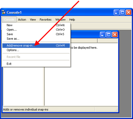 Fig. 25. Adding snap-in
This will open the Add/Remove Snap-in dialog box. Click Add.
This will open the Add Isolated Snap-In dialog box. Select 1C:Enterprise 8.3 Servers from the list, click Add, and close the dialog box by clicking Close.
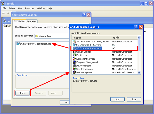 Fig. 26. Snap-in selection
In the Add/Remove Snap-in dialog box, click OK. This will connect the administration utility to the Microsoft management console.
5.2.3. Registering a Working Server Instance
When you first start the administration utility, the tree of main servers includes only the working server installed on the computer running the administration utility (provided that the server agent is running on this computer).
To display the full list of main servers, select and expand the 1C:Enterprise 8.3 Central Servers branch in the main server tree.
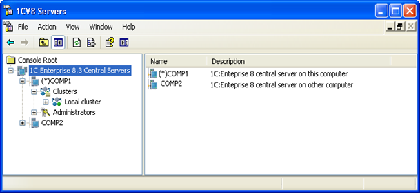 Fig. 27. Main server tree
The tree of main servers contains a list of main servers to which the utility is connected. Each main server is identified by the name of computer running it. The properties field displays a list of main servers. The list contains network addresses and descriptions of all main servers.
5.2.3.1. Connecting the Utility to a Main Server
To connect the utility to a new main server, click Create – 1C:Enterprise 8.3 main server in the context menu or execute the same main menu command of the utility.
This will open the dialog box of main server properties.
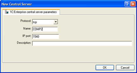 Fig. 28. New main server
You need to enter the following data in the dialog box fields:
- Protocol
- Main server connection protocol selected from the list. Default value: -tcp. This field contains the protocol by which the administration utility connects to the main server agent. tcp is the only supported value.
- Name
- Network address of the main server running the server agent.
- IP port
- Number of a network port of the server agent that is running on the main server. Default value: 1540. The server agent port is specified at startup (see Running the server agent).
- Description
- Arbitrary description of the main server.
5.2.3.2. Viewing and Editing Main Server Properties
To view or edit properties of a main server, select the server in the list of main servers and execute the Properties context menu command or the same main menu command of the utility.
This will open the dialog box of main server properties described in the previous section (see Connecting the utility to a main server).
5.2.3.3. Disconnecting a Main Server from the Utility
To remove a main server from the list of main servers in the utility, select the server in the list and execute the Remove context menu command or the same main menu command of the utility.
5.2.3.4. Disconnecting a Main Server from the Utility
The 1C:Enterprise server cluster administration utility can be disconnected from a main server. However, connection settings to the main server will not be deleted.
To disconnect the utility from a main server, select the server in the list of main servers and execute the Disconnect context menu command or the same main menu command of the utility.
5.2.4. Operations with the List of Main Server Administrators
In a server cluster, you can create a list of main server administrators so that administrative operations (for example, adding a new cluster or viewing the list of main server administrators) can be performed by authenticated users only.
By default, the list of main server administrators is empty. This means that authentication of a main server administrator is not required to perform the above actions.
To display the list of main server administrators, select a server in the main server tree. After that, select and expand the Administrators branch.
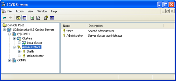 Fig. 29. List of server cluster administrators
The main server tree contains the list of administrators of the selected main server. Each administrator is identified by name. The properties field displays a list of administrators of the selected main server. The list contains administrator names and descriptions.
For each working server that is not assigned as a main server of a cluster and that has a non-empty list of main server administrators, the administrator list must include an administrator with OS authentication of the user on whose behalf ragent is running on the main server of the cluster or an administrator whose name and password match those of an administrator of the main server of the cluster.
5.2.4.1. Creating a Main Server Administrator
To add a new main server administrator, select the required server in the main server tree, right-click Administrators and then click Create – Administrator or execute the same main menu command of the utility.
This will open the dialog box of main server administrator properties.
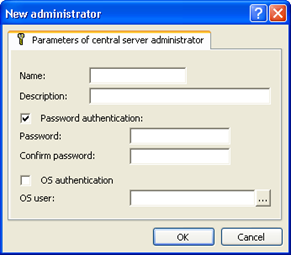 Fig. 30. New main server administrator
You need to enter the following data in the dialog box fields:
- Name
- Name of the main server administrator.
- Description
- Arbitrary description of the main server administrator.
- Password authentication
- Indicates whether password authentication is enabled. It is set by default.
- Password
- Password of the main server administrator.
- Password confirmation
- Password confirmation.
- OS authentication
- Indicates whether OS authentication is enabled.
- User
- Operating system user. Allowed format: \domain name\user name. For example: \domainname\username. You can specify a user directly by entering their name or select a user from the OS user list available on a computer running the infobase administration utility. To select a user from the list, click "..." in the opened dialog box and select a OS user.
Two authentication methods are supported for main server administrators:
-
Password authentication
-
OS authentication
Password authentication opens the dialog box of main server administrator authentication where you need to enter a username and a password.
If you select OS authentication, you are not required to enter a username or a password. The authentication dialog box is not displayed. The main server administrator is selected depending on the OS user on whose behalf connection was established.
5.2.4.2. Viewing and Editing Main Server Administrator’S Properties
To view or edit properties of a main server administrator, select the administrator in the list of main server administrators and execute the Properties context menu command or the same main menu command of the utility.
This will open the dialog box of main server administrator properties.
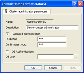 Fig. 31. Main server administrator's properties
All properties, except for the administrator name, are editable. Values of the Password and Password confirmation fields are hidden.
5.2.4.3. Deleting a Main Server Administrator
To delete a main server administrator, select the administrator in the list of main server administrators and execute the Delete context menu command or the same main menu command of the utility.
5.2.4.4. Main Server Administrator Authentication
Authentication is automatically requested from a main server administrator when they attempt to perform an action requiring authentication (provided that the list of main server administrators is not empty). This opens the dialog box of main server administrator authentication.
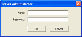 Fig. 32. Administrator authentication
You need to enter the following data in the dialog box fields:
- Name
- Name of the main server administrator.
- Password
- Password of the main server administrator.
5.2.5. Operations with the List of Clusters
To display the list of clusters registered on a main server, select a server in the main server tree. After that, select and expand the Clusters branch.
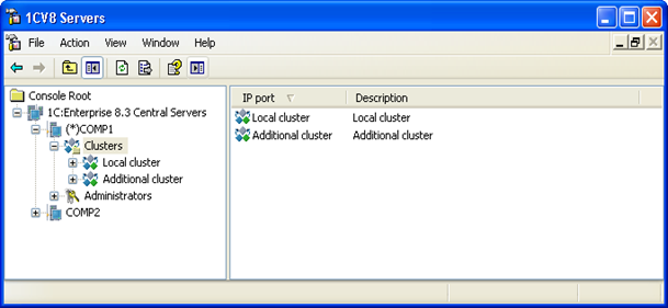 Fig. 33. List of clusters
The main server tree contains a list of clusters for the selected main server. Each cluster is identified by a network port number. The properties field displays a list of clusters of the selected main server. The list contains port numbers and descriptions of all clusters.
5.2.5.1. Adding Clusters
To add a new cluster to a main server, select the required server in the main server tree, right-click Clusters and then click Create – Cluster or execute the same main menu command of the utility.
This will open the dialog box of cluster properties.
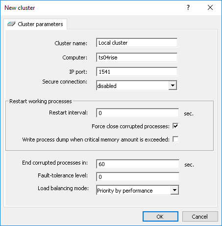 Fig. 34. New cluster
You need to enter the following data in the dialog box fields:
- Cluster name
- Arbitrary description of the cluster.
- Computer
- Name of the main server hosting the cluster. Not editable.
- IP port
- Network port number of the cluster manager. Default value: 1541.
- Secure connection
- Cluster security level. Selected from the list (allowed values: Never, Connection only, and Always.) Default value: Never. For more information on the cluster security levels, see Security of data exchanged between a client and a server cluster.
- Allow logging access right audit events
- NOTE. Available only for CORP licenses.
Allows you to manage logging of access right audit events for all infobases of the server cluster.
- Restart schedule
- String that contains a schedule for restarting working processes of the server cluster. The schedule is set in cron format. The format is borrowed from the cron utility from Linux/Unix (the utility is used to set a schedule for performing various actions in the operating system). For details on the format, see Format of the schedule string for restarting working processes (cron format). A production server can have its own schedule for restarting working processes, which takes precedence over the cluster schedule. If the schedule line is not specified, scheduled restart of working processes is not performed.
Working processes are restarted as follows:
-
An existing working process (hereinafter referred to as "old" process) is disconnected. The working process in disconnected mode:
-
Continues processing old connections with infobases.
-
Accepts new connections to infobases being processed by this working process.
-
Does not accept new connections to infobases not being processed by this working process.
-
-
A new working process (hereinafter referred to as "new" process) is registered and started in the server cluster.
-
In the new working process, contexts of infobases being processed by the old working process are created. Infobase configurations are imported to the created contexts. Contexts are created by system background jobs, which have the following characteristics:
-
They are displayed in the list of connections as System background job with the SystemBackgroundJob application ID.
-
When a system background job is started, the functionality assignment rules are not considered.
-
A system background job runs without session creation, and its operation is not recorded in the event log.
-
A system background job can be interrupted by the server cluster administration tools.
-
-
After infobase contexts are generated in the new working process, the old working process:
-
Stops accepting all new connections.
-
"Transfers" existing connections to the new working process.
-
-
The old working process is closed if one of the following conditions is met (combined "by OR"):
-
After successful transfer of all existing connections.
-
After the time period specified in Terminate corrupted processes in.
-
-
The old working process is unregistered from the server cluster.
If there are several working processes running on the production server, they are restarted sequentially. First, one working process is restarted (as described above), then the next, and so on. If there are several production servers in the cluster, working processes on different production servers are restarted simultaneously.
- Terminate corrupted processes
- If the cluster monitoring tool considers a working process corrupted, this check box controls whether this process can be terminated forcibly. This check box does not affect the monitoring process. For more information on the cluster monitoring, see Cluster monitoring system.
- Write process dump when critical memory amount is exceeded
- Defines whether an abnormal termination dump of a working process must be generated if the server cluster terminates the working process. This situation might occur if, during cluster state monitoring, the value set in the Critical amount of process memory working server parameter is exceeded. For the algorithm that can result in forced termination of a working process, see Adding production servers to a cluster.
A dump is generated according to the current settings of abnormal termination dump generation.
- Terminate corrupted processes in \_ seconds
- Time period after which a corrupted working process is terminated regardless of any active connections to it. All connections to this process are abnormally terminated. Value of this property can be changed while the cluster is running. A zero value means that processes will not be terminated. A cluster manager that exceeds the limit of used memory is always restarted without waiting.
- Fault tolerance level
- Fault tolerance level defines the maximum number of working servers in the cluster whose concurrent failure would not result in abnormal termination of any user sessions. For more information, see Fault tolerance level.
- Load balancing mode
- This parameter defines criteria to select a working process upon establishing a new connection. For more information, see Establishing a new connection.
- Verification period
- Connection interruption check frequency (in milliseconds). See Connection break monitoring. If at least one of the Verification period or Verification timeout parameters in the cluster settings is different from 0, these values will be used. Otherwise, the server cluster startup command-line options will be used (see Running the server agent).
- Verification timeout
- Check timeout of the connection break monitoring system (in milliseconds). See Connection break monitoring. If at least one of the Verification period or Verification timeout parameters in the cluster settings is different from 0, these values will be used. Otherwise, the server cluster startup command-line options will be used (see Running the server agent).
5.2.5.2. Viewing and Editing Cluster Properties
To view or edit cluster properties, select a cluster in the cluster list of the main server and execute the Properties context menu command or the same main menu command of the utility.
This will open the dialog box of cluster properties.
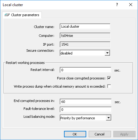 Fig. 35. Server cluster properties
When you change the Secure connection property of a running server cluster, you need to restart the cluster to apply the new property value.
5.2.5.3. Calling Operation to Apply Functionality Assignment Rules
Functionality assignment rules do not take effect until they are explicitly applied. The list of rules edited in the cluster console does not affect the operation of the server cluster until the rules are applied. The application may be full or partial.
In the case of partial application, services that support migration between working servers without data loss are reassigned. Other services are reassigned only if new functionality assignment rules do not allow these services to remain at their previous locations or the working servers running these services at the time of partial application are unavailable. Full application affects all services regardless of formal characteristics of the services.
When performing full application, any client applications connected to the server cluster on which the operation is performed may be terminated. This situation is also possible in case of partial application if all services have been reassigned, not only those that allow migration without data loss.
To apply the rules, right-click the server cluster and select Apply functionality assignment rules (partial) or Apply functionality assignment rules (full).
5.2.5.4. Deleting Clusters
To delete a cluster, select it in the cluster list of the main server and execute the Delete context menu command or the same main menu command of the utility.
5.2.6. Operations with the List of Working Servers in a Cluster
To display the list of working servers in a cluster, select a server in the main server tree and a cluster registered on this server. After that, select and expand the Working servers branch.
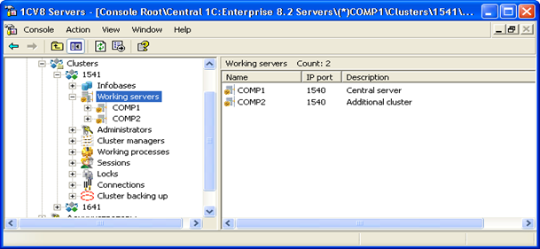 Fig. 36. List of working servers
The main server tree contains a list of working servers in a cluster. Each working server is identified by a network name. The properties field displays a list of working servers of the selected cluster. The list contains the name and description of each server, and the network port number of the server agent running on this server.
When you create a default cluster, the working server where it was created is added to the cluster automatically. The Main server check box is automatically selected for this working server.
5.2.6.1. Adding Production Servers to a Cluster
To add a new production server to a cluster, select a main server in the main server tree and then select a cluster registered on this server. After that, right-click Production servers and then click Create – Production server or execute the same main menu command of the utility.
This will open the dialog box of working server properties.
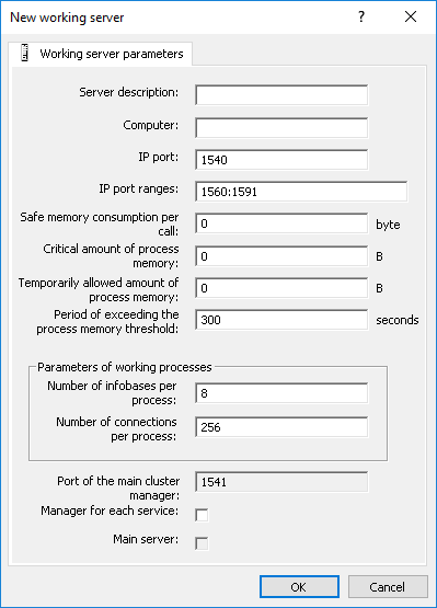 Fig. 37. New working server
You need to enter the following data in the dialog box fields:
- Description
- Arbitrary description of the cluster server.
- Computer
- Network address of the working server running the server agent.
- IP port
- Number of a network port of a server agent that is running on the specified computer. Default value: 1540.
- IP port range
- Range of network ports that will be used to assign addresses to working processes created on this server. Default value: 1560:1591.
- Safe memory consumption per call
- NOTE. Available only for CORP licenses.
The amount of memory in bytes that is considered safe to use during a server call and does not cause the call to be interrupted if the Temporarily allowed amount of process memory limit is exceeded.
It can take values from -1 to 9 223 372 036 854 775 807:
-
-1. Any server call will be interrupted if the Temporarily allowed amount of process memory limit is exceeded.
-
0. The safe memory consumption per call is calculated automatically as a 10% share of the value specified in the Temporarily allowed amount of process memory property.
- Critical amount of process memory
- Defines the critical memory amount for cluster processes (working processes and cluster managers). The total amount of memory occupied by cluster processes (working processes and cluster managers) on the production server, which can impact the production server performance when exceeded. Used by the cluster monitoring tool (for details, see Cluster monitoring system).
This parameter can take values from -1 to 9 223 372 036 854 775 807, where:
-
-1. The allowed memory amount available for cluster processes on this production server is unlimited.
-
0. The allowed amount of memory available to working processes of the cluster on this production server is limited to 95% of server RAM.
Default value: 0.
- Temporarily allowed amount of process memory
- Defines the size of the temporarily allowed amount of memory occupied by cluster process (working processes and cluster managers) on the production server, in bytes. If the amount of memory occupied by cluster processes exceeds the parameter value, the system does not assign new infobase connections to this server due to its decreased performance.
This value is used to monitor the amount of memory consumed by working processes in general or by a specific server call:
-
Working process memory monitoring. Performed by the cluster monitoring tool (for details, see Cluster monitoring system).
-
Server call memory monitoring.
Each working process of a cluster determines the amount of memory consumed by cluster processes on this working server (hereinafter referred to as ProcessMemory). ProcessMemory is updated every two seconds.
When you make a server call, the current value of ProcessMemory is registered (hereinafter referred to as CurrentProcessMemory) and the difference between Temporarily allowed amount of process memory and CurrentProcessMemory is calculated (hereinafter referred to as MemoryLimitPerCall). If MemoryLimitPerCall is less than Safe memory consumption per call, MemoryLimitPerCall takes the value of Safe memory consumption per call.
During the call, the amount of memory consumed by the call (hereinafter referred to as MemoryPerCall) is calculated.
If, upon memory allocation, MemoryPerCall is greater than MemoryLimitPerCall in a single server call, this call is abnormally terminated with an exception. In this case, the EXCP event is logged with the following information:
-
Exception text
-
Exception context
It can take values from -1 to 9 223 372 036 854 775 807:
-
-1. The temporarily allowed memory amount available for cluster processes on this production server is unlimited.
-
0. The allowed amount of memory available to working processes of the cluster on this production server is limited to 80% of the server's computer RAM.
Default value: 0.
- Period of exceeding the memory threshold
- Defines the time period during which the amount of RAM occupied by cluster processes can exceed the value of Temporarily allowed amount of process memory. This parameter will be used only if its value is not equal to 0 and the value of Temporarily allowed amount of process memory differs from -1. Used by the cluster monitoring tool (for details, see Cluster monitoring system).
Default value: 300 seconds.
- 1C:Enterprise server service name (SPN)
- If you specify any value other than an empty string for this property, the value will be used as 1C:Enterprise server service name (Service Principal Name, SPN). When you use Windows authentication, the server service name is required to configure limited Kerberos delegation in the domain.
If this property is not specified, OS authentication with limited delegation is not available for 1C:Enterprise server cluster on Windows.
For how to create a server service, see Creating a server service name for Kerberos authentication.
- Restart schedule
- String that contains a schedule for restarting working processes of this production server. The schedule is set in cron format. The format is used by the cron utility from Linux/Unix to manage the execution of tasks according to a certain schedule. For details on the format, see Format of the schedule string for restarting working processes (cron format). The schedule for restarting the production server takes precedence over the schedule set for the cluster that includes the production server. If the schedule line is not specified, scheduled restart of working processes is not performed.
For a description of the working process restart, see Adding clusters (in the description of the same-named parameter).
- Number of infobases per process
- NOTE. Available only for CORP licenses.
Maximum number of infobases whose connections can be maintained by a single working process of this server. A zero value means that no limit is set.
If the number of infobases exceeds this limit, the server cluster will create an additional working process on this production server.
- Number of connections per process
- Number of infobase connections that can be maintained by a single working process of this server. A zero value means that no limit is set.
If the number of connections maintained by a working process exceeds this limit, the server cluster will create an additional working process on this server.
- Main cluster manager port
- Network port number of the main cluster manager running on this working server. This network port is used when generating the server cluster address for the client application. The address is as follows: <Computer property>: <Main cluster manager port>. If the Computer property is set to COMP1 and the Main cluster manager port property is set to 2541, the server cluster address is COMP1:2541.
The value of this parameter is ignored if the Main server check box is not selected.
- Manager for each service
- Allocates a separate cluster manager for each service type (see Cluster services). If this check box is selected, a separate cluster manager will be created for each cluster service type. Otherwise, all cluster services are assigned to the same cluster manager of the working server.
Every additional cluster manager will use one port from the range of network port for dynamic selection (set when starting the server cluster).
If you create a cluster manager for each cluster service, name the manager as follows: Additional cluster manager (<Service description>). For example, the manager for the session data service will have the following description: Additional cluster manager (Session data service). The main cluster manager is always described as Main cluster manager.
- Main server
- If the check box is selected, the cluster registry is synchronized with this working server. The address of the working server can be used to connect client applications to the cluster.
- Set forbidding functionality assignment rule
- Selecting this checkbox when creating a new production server will lock the assignment of any sessions to the created server. This might be useful if the default production server settings do not meet your needs. With this checkbox, you can create a server, configure it, and only then allow assigning sessions by applying the required rules.
When the checkbox is selected, a functionality assignment rule with the following parameters is created and applied on the created server:
-
Assignment rule object: Any assignment rule object.
-
Rule type: Do not assign.
-
Infobase name: not specified.
-
Additional parameter value: not specified.
-
Priority: 0.
You can only set this property when creating a production server.
5.2.6.2. Viewing and Editing Cluster Server Properties
To view or edit cluster server properties, select a server in the list of cluster servers and execute the Properties context menu command or the same main menu command of the utility.
This will open the dialog box of working server properties.
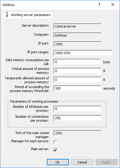 Fig. 38. Properties of a production server
In addition to the properties that are displayed in the dialog box when creating a new server, the properties dialog box of the existing server also displays the internal network port of the server agent that was automatically assigned on the server agent startup and is used for interaction between the server cluster processes.
In the properties of an existing server, only the network port range is editable.
5.2.6.3. Removing Servers from a Cluster
Removing a working server can abnormally terminate client connections. To avoid this, add the following functionality assignment rule (with the highest priority) before removing the server:
-
Assignment rule object: Any assignment rule object.
-
Rule type: Do not assign.
-
Infobase name: not specified.
-
Additional parameter value: not specified.
After that, apply the new set of rules and wait until existing connections are closed. Then, remove the working server using the Remove context menu command or the same main menu command.
You cannot delete the last working server with selected Main server check box.
5.2.6.4. Functionality Assignment Rules
To view the list of functionality assignment rules for a specific working server, select the server in the main server tree. After that, select a cluster and a working server. Then, select the Functionality assignment rules branch.
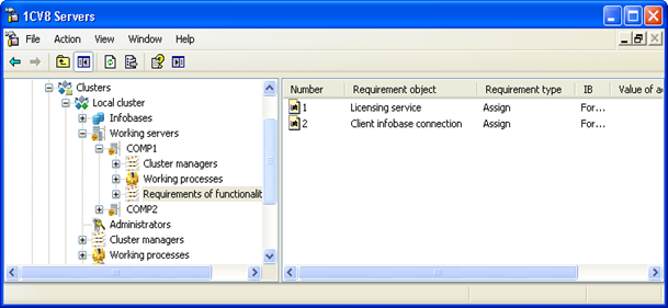 Fig. 39. Functionality assignment rules
To create a new rule, click Create – Functionality assignment rule in the context menu or in the Action submenu of the main menu.
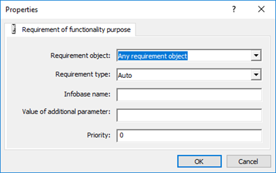 Fig. 40. New functionality assignment rule
Selected rules are processed in the order they are placed in the rule list of a specific server. The processing order (rule priority) is determined by the Number column of the functionality assignment rule list. The smaller the number, the higher the priority and the earlier the rule will be processed. To change the priority of a rule, hover the pointer over the rule, right-click it (or click Action in the main menu), and select the Increase rule priority or Reduce rule priority command, depending on whether you need to increase or decrease the rule priority.
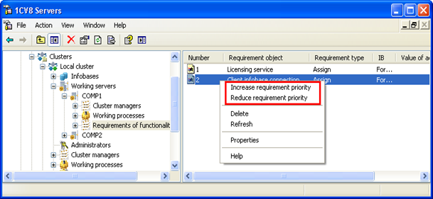 Fig. 41. Changing a rule priority
Functionality assignment rules do not take effect until they are explicitly applied. For more information on applying functionality assignment rules, see Calling operation to apply functionality assignment rules.
5.2.6.5. Cluster Service Settings
To view the list of cluster service settings for a specific production server, select the server in the main server tree. After that, select a cluster and a working server. Then, select the Service settings branch. For more information about cluster service settings, see Cluster services.
To create a new service setting, click Create – Service setting in the context menu or in the Action submenu of the main menu.
Next, in the Service name field, select the service for which you plan to change the data storage directory. Specify the new data storage directory in the Service data directory field. If the service you configure can be separated by infobases, specify the name of the required infobase in the Infobase name field. After saving, the setting is not automatically applied to the server cluster.
For the server cluster to start using the new service data directories, apply the made changes. To do this, use the Apply settings command for the production server for which the service settings were created or deleted.
You cannot change the existing service settings. You can only delete an existing setting and create a new one for the same cluster service.
5.2.7. Operations with the List of Infobases
To display the list of infobases registered in a cluster, select a server in the main server tree and a cluster registered on this server. After that, select and expand the Infobases branch.
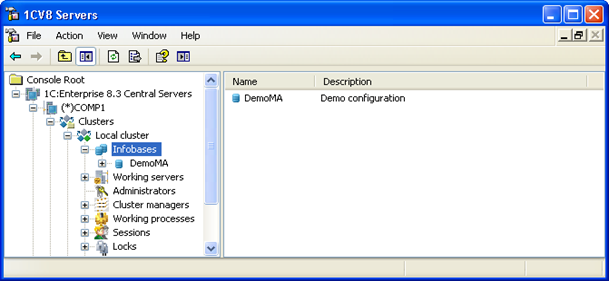 Fig. 42. List of infobases
The main server tree contains a list of infobases in the cluster. Each infobase is identified by name. The properties field displays a list of infobases of the selected cluster. The list contains names and descriptions of all infobases.
5.2.7.1. Registering a New Infobase
You can register a new infobase in a server cluster:
-
From the client application
-
Directly in the server cluster
When you add a new infobase in the client application, it is automatically registered in the server cluster.
To register a new infobase using the server cluster administration utility, select a main server in the main server tree and a cluster registered on this server. After that, right-click Infobases and then click New – Infobases or execute the same main menu command of the utility.
This will open the dialog box of infobase properties.
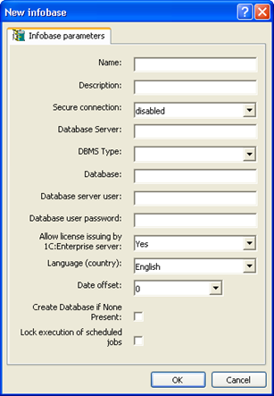 Fig. 43. New infobase
Infobase parameters are identical to the parameters of a new infobase created using 1C:Enterprise startup window.
Please pay attention to the Allow license issuing by 1C:Enterprise server parameter. This parameter controls whether 1C:Enterprise server can issue client licenses. If the parameter is set to Yes, 1C:Enterprise server will issue client licenses whenever the client application fails to get one. If the parameter is set to No, 1C:Enterprise server will not issue client licenses. In this case, the client application that could not obtain the license displays the diagnostic message: License is not found. No dongle or software license is found.
When you register a new infobase, the system checks whether an infobase with the same name already exists on the specified database server. If the infobase exists, a connection with it will be established. If the existing database already contains 1C:Enterprise infobase data, a connection will be established with the existing infobase. If the database does not contain infobase data, a new 1C:Enterprise infobase will be created in it.
5.2.7.2. Viewing Infobase Properties
To view and edit infobase properties, select an infobase in the infobase list and execute the Properties context menu command or the same main menu command of the utility.
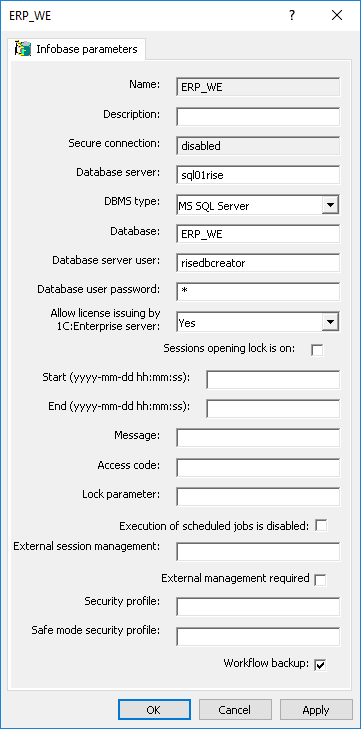 Fig. 44. Infobase properties
In the window of infobase parameters, you can edit database server name, database name, select another DMBS to be used, and change username and password of the database user.
You can also edit properties related to locks of user sessions with this database.
- Session start lock enabled
- If the check box is selected, infobase session startup is locked. Where:
-
Existing sessions remain active.
-
Existing sessions can start background jobs.
-
Existing sessions can establish connections.
-
New sessions cannot be opened.
-
New connections cannot be established, except by existing sessions.
- Start (lock start date/time)
- Lock takes effect if the current time exceeds the property value.
- End (lock end date/time)
- If the property value differs from the zero date and is less than or equal to the current time, the lock is no longer applied.
- Message
- Custom text included in the error message that is displayed upon an attempt to connect to a locked infobase.
- Access code
- String to be added to the /UC command-line option or to the UC connection string parameter to connect to the infobase despite the connection lock.
- Lock parameter
- Arbitrary text. It can be used in configurations for various purposes.
- Scheduled job lock enabled
- If the check box is selected, scheduled jobs for this infobase are locked.
- External session management
- String that describes web service parameters of external session management.
An example of a string with web service description:
wsdl=http://server/sm/ws/manager?wsdl;ns=http://www.sessioncontrol.org;srvc=manager;port=managerSoap;tout=10;wsver=4;- External management required
- If the check box is selected, an error occurs and the infobase cannot be connected to when the web service of external session management is unavailable. If the checkbox is cleared and the web service is unavailable, the infobase can be connected and the number of concurrent sessions is not restricted.
- Security profile
- If you specify the security profile name (see Operations with the list of security profiles) in this field, the security profile applies its restrictions to the server-side application.
You can enter the security profile name manually or select it from the drop-down list. The drop-down list includes existing profiles appropriate for this input field.
- Safe mode security profile
- If you specify the name of a security profile in this field, the security profile applies its restrictions to the application segments running in safe mode.
You can enter the security profile name manually or select it from the drop-down list. The drop-down list includes existing profiles appropriate for this input field.
- Working process backup
- If this check box is selected, the server cluster starts to create backup working processes for this infobase. For more information on working process backup, see Working process backup.
- Deny local speech recognition
- If the check box is selected, local speech recognition in the infobase will be denied. To recognize speech, you will be able to use the remote (cloud) mode only.
- Delay for configuration dump by working process
- Possible values: from 0 to 4,294,967.
Defines the time (in seconds) in which the working process releases infobase data after the latest infobase connection in this working process is broken. As long as the data is not released, establishing new connections and starting background jobs takes less time. Data can be released earlier if a working process is completed or exclusive access to an infobase or database is requested. You can set this parameter if the server capacity is designed to support operations in all infobases registered in the server cluster at the same time. Configuration dump delay lowers overheads of starting scheduled jobs by excluding extra configuration data exports/imports.
For more information on the system behavior if there are no active sessions, see Running scheduled jobs without active sessions.
- Minimal startup period for scheduled jobs
- Possible values: from 0 to 4,294,967.
Defines a minimum start period for each scheduled infobase job (in seconds) if the infobase has no active user sessions. Helps to reduce server load without changing the configuration when the infobase has no interactive users. Start of multiple jobs of one infobase will be grouped by time to minimize overheads of the configuration data import/export.
For more information on the system behavior if there are no active sessions, see Running scheduled jobs without active sessions.
- Maximum startup offset for scheduled jobs
- Possible values: from 0 to 4,294,967.
Determines the maximum delay of the start of each scheduled job of the infobase (in seconds) in relation to the schedule, taking into account the value of the Minimal startup period for scheduled jobs parameter if there are no active user sessions in the infobase. It is only used if the Minimal startup period for scheduled jobs parameter is not set to zero. Together with the Minimal startup period for scheduled jobs parameter, it allows you to exclude peak loads on the server while performing scheduled jobs of various infobases at different times within the values of this parameter. Both parameters can be used provided there are many infobases registered in the cluster, most of which users do not use simultaneously, and the server capacity is not designed to support operations in all infobases at the same time.
For more information on the system behavior if there are no active sessions, see Running scheduled jobs without active sessions.
5.2.7.3. Deleting Infobases
To delete an infobase, select an infobase in the infobase list and execute the Delete context menu command or the same main menu command of the utility.
As a result of the command execution, a warning question appears on the screen: Delete the infobase? If you confirm, you will be prompted to select one of three infobase deletion options.
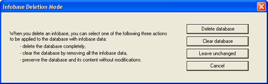 Fig. 45. Infobase deletion mode
-
Delete database. If you select this option, the infobase will be unregistered in the server cluster and the respective database on the database server will be deleted.
-
Clear database. If you select this option, the infobase will be unregistered in the server cluster and all the data will be deleted from the database on the database server. The database will not be deleted from the database server.
-
Leave unchanged. If you select this option, only the infobase will be unregistered in the server cluster. No changes will be made to the database.
If the Delete database option is selected but there are user connections to this database, the infobase will be unregistered in the server cluster. When trying to delete the database, the database server will display an error message. For example:
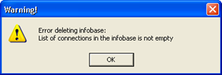 Fig. 46. Error deleting infobase
5.2.7.4. Operations with the List of Binary Data Storages
In client/server mode, the infobase can be connected to one or several binary data storages. If such storages are connected to the infobase, the following operations will be available to the administrator:
-
Built-in storage: backup and restore operations, storage cleanup.
-
S3 storage: storage cleanup.
Creating and deleting binary data storages in the cluster management console is not supported.
To see the list of connected storages, select the infobase, and then expand the Binary data storages branch.
To open a dialog box for managing the selected storage, right-click the storage in the list and then click Manage. You can also find this command in the main menu of the utility.
This will open the dialog box for binary data storage management.
On this page, you can create a backup of the binary data storage. To specify the type of backup to be created (full or differential), use the Backup type radio button. The Full backup file name and Differential backup file name fields allow you to specify file names for a particular backup type. Remember that a differential backup is always performed relative to a full backup. To clear the storage after creating a backup, use the same-named checkbox. To leave unused data for the specified interval (relative to the current date), use the Save deleted data for the last X days field. To start the configured operation, click Create.
To restore the built-in binary data storage from its pre-created backup, use the Restore from backup tab.
To specify the type of backup to restore the data from (full or differential), use the Backup type radio button. The Full backup file name and Differential backup file name fields allow you to specify file names for a particular backup type. To restore from a differential backup, specify the same full backup file that was used to create the differential backup. To start the configured operation, click Restore.
On the Clear storage tab, you can clear the storage of unused data without linking it to the backup operation.
The administrator must specify the date and time before which the deleted (unused) data must be cleared (starting "from the past"). The date and time are specified in the Clear data before date fields. To start the operation, click Clear.
-
Binary data storage (see Binary data storage).
-
Built-in storage backup (see Backup).
5.2.8. Operations with the List of Cluster Administrators
You can create a separate list of administrators for each cluster registered on a main server so that only authenticated users can perform administrative actions with the cluster.
By default, the list of cluster administrators is empty. This means that cluster administrator authentication is not required.
To display the list of cluster administrators, select a server in the main server tree and a cluster registered on this server. After that, select and expand the Administrators branch.
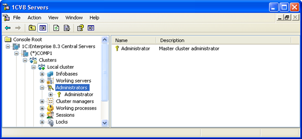 Fig. 47. List of cluster administrators
The main server tree contains the list of administrators of the selected cluster. Each administrator is identified by name. The properties field displays a list of administrators of the selected cluster. The list contains names and descriptions of all administrators.
5.2.8.1. Adding Cluster Administrators
To add a cluster administrator, select a server in the main server tree and a cluster registered on this server. After that, right-click Administrators and then click Create – Administrator or execute the same main menu command of the utility.
This will open the dialog box of cluster administrator properties.
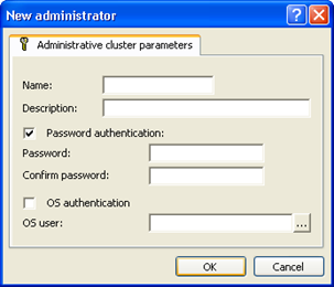 Fig. 48. New cluster administrator
You need to enter the following data in the dialog box fields:
- Name
- Name of the cluster administrator.
- Description
- Arbitrary description of the cluster administrator.
- Password authentication
- Indicates whether password authentication is enabled. It is set by default.
- Password
- Password of the cluster administrator.
- Password confirmation
- Password confirmation.
- OS authentication
- Indicates whether OS authentication is enabled.
- User
- Operating system user. The username must follow this format: \domain name\user name. For example: \domainname\username. You can specify a user directly by entering their name or select a user from the OS user list available on a computer running the infobase administration utility. To select a user from the list, click "..." in the opened dialog box and select a OS user.
Two authentication methods are supported for cluster administrators:
-
Password authentication
-
OS authentication
Password authentication opens the dialog box of cluster administrator authentication (see Cluster administrator authentication), where you need to enter a username and a password.
If you select OS authentication, you are not required to enter a username or a password. The authentication dialog box is not displayed. The cluster administrator is selected depending on the OS user on whose behalf connection was established.
If no authentication method is specified for an administrator, this administrator can perform only those actions that do not require authentication.
5.2.8.2. Viewing and Editing Cluster Administrator Properties
To view or edit cluster administrator properties, select an administrator in the list of cluster administrators and execute the Properties context menu command or the same main menu command of the utility.
This will open the dialog box of cluster administrator properties.
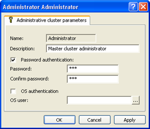 Fig. 49. Cluster administrator properties
You can edit all properties, except for administrator's name. Values of the Password and Confirm password fields are hidden.
5.2.8.3. Deleting Cluster Administrators
To delete a cluster administrator, select the administrator in the list of cluster administrators and execute the Delete context menu command or the same main menu command of the utility.
5.2.8.4. Cluster Administrator Authentication
Authentication is automatically requested from a cluster administrator when they attempt to perform an action requiring authentication (provided that the list of cluster administrators is not empty). This opens the dialog box of cluster administrator authentication.
You need to enter the following data in the dialog box fields:
- Name
- Name of the cluster administrator.
- Password
- Password of the cluster administrator.
5.2.9. Viewing the List of Cluster Managers
You can view and edit the list of cluster managers. By default, one cluster manager is set as the primary cluster manager. It is defined in all clusters.
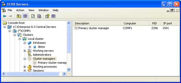 Fig. 50. Cluster managers
The cluster determines the number and location of cluster managers. The number and location of cluster managers depend on functionality assignment rules and values of the Manager for each service and Main server production server properties. Administrators cannot manually add or delete cluster managers.
To view description of a cluster manager, right-click it and select Properties.
This will open a window where you can edit the description of the cluster manager.
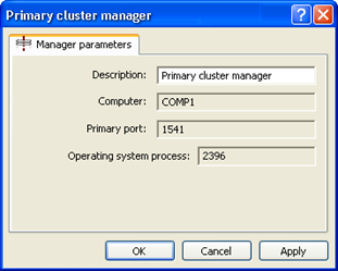 Fig. 51. Cluster manager properties
5.2.10. Viewing the List of Working Processes
The list of working processes can be displayed:
-
For the entire cluster
-
For a cluster server
To display the list of working processes for the entire cluster, select a server in the main server tree and a cluster registered on this server. After that, select and expand the Working processes branch.
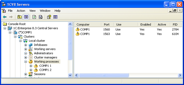 Fig. 52. Working process list
To display the list of working processes for a certain server in a cluster, select a server in the main server tree, a cluster and a server in this cluster. After that, select and expand the Working processes branch.
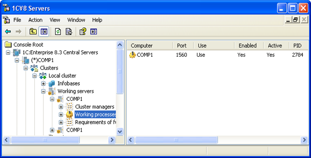 Fig. 53. List of working processes on a specific working server
The main server tree contains a list of working processes. Each working process is identified by a server name and a sequence number in that working server. The properties field displays technical information that describes a particular working process. Displayed parameters are described below.
You can disable working processes in the working process list. To do this, right-click the working process and then click Disable or click Main menu – Actions – Disable. In this case, the working process will be disabled. To find out how to disable working processes, see Adding clusters (in the description of the Restart schedule parameter).
To view the properties of a working process, right-click a working process in the list of working processes and then click Properties. You can also click Main menu - Action - Properties. Administrators cannot manually add or delete working processes.
This will open the dialog box of working process properties.
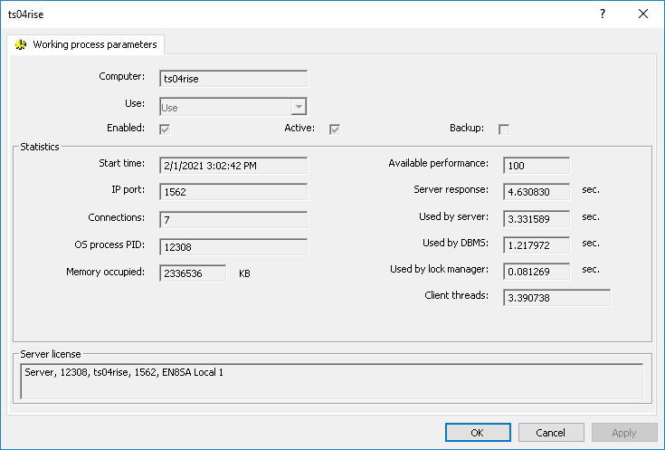 Fig. 54. Working process properties
The dialog box of working process properties contains the following fields, which you cannot edit:
- Computer
- Name of the working server where the working process runs.
- Enabled
- The working process is currently enabled and can be used.
- Active
- The working process is currently in use.
- Backup
- Currently, this is a backup working process (for details, see Working process backup).
- Start time
- Time of the last working process startup.
- IP port
- Working process network port that is selected by the system dynamically from network ports specified for this server upon working process startup.
- Connections
- Current number of connections maintained by the working process.
- OS process PID
- Process number in terms of the OS running the working process.
- Occupied memory
- Memory amount occupied by the working process.
- Available performance
- Current available performance. For more information, see Available performance of a working process.
- Server response
- Average time spent to maintain a single connection. It is equal to the sum of the values of the following fields:
-
Used by server
-
Used by DBMS
-
Used by lock manager
- Used by server
- Average time spent by the working process to maintain a single connection.
- Used by DBMS
- Average time spent by the DBMS to maintain a single connection.
- Used by lock manager
- Average time spent by the lock manager to maintain a single connection.
- Client threads
- Average number of client threads processed by the working process. Used by the system to calculate working process performance.
- Server license
- Indicates a server license to be used by this working process and its characteristics. For more details on the generated string, see License description string format.
5.2.11. Operations with the List of Sessions
5.2.11.1. General Information
The list of sessions can be displayed:
-
For the entire cluster
-
For an infobase
To display the list of sessions for the entire cluster, select a main server in the main server tree and a cluster registered on this server. After that, select and expand the Sessions branch.
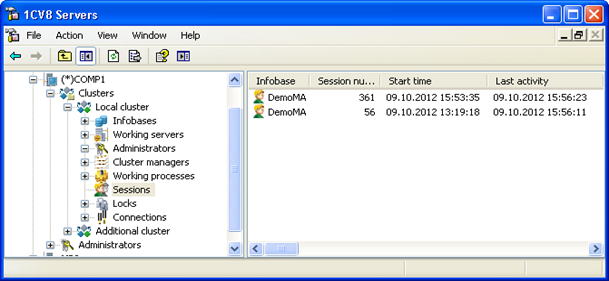 Fig. 55. List of server cluster sessions
To display the list of connections for a specific database, select a main server in the main server tree, a cluster and an infobase. After that, select and expand the Sessions branch.
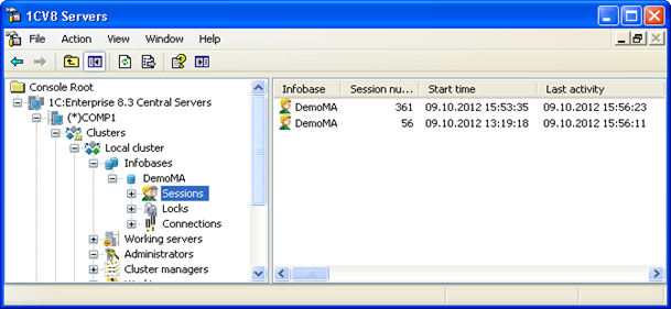 Fig. 56. List of infobase sessions
The properties field displays a list of sessions that contains the following information (the table is ordered by the indicator name):
| Indicator | Description |
|---|---|
| Client IP | IP of the client application that started the session. |
| DBMS call duration (5 min) | Total duration of DBMS calls in completed server calls in the last 5 minutes (in seconds). |
| DBMS call duration (total) | Total duration of DBMS calls in completed server calls since the session start (in seconds). |
| DBMS call duration (current) | Total duration of DBMS calls since the current incomplete server call was initiated (in seconds). |
| Call time (5 min) | Total duration of server calls completed in this session in the last five minutes (in seconds). |
| Call time (total) | Total duration of server calls since the session start (in seconds). |
| Call time (current) | Execution time of the current incomplete server call (in seconds). |
| Service call time (5 min) | Total running time of all cluster services in completed server calls in the last 5 minutes (in seconds). |
| Service call time (total) | Total running time of all cluster services in completed server calls since the session start (in seconds). |
| Service call time (current) | Running time of the cluster service in the current incomplete call (in seconds). Name of the service is specified in the Current service property. |
| Start time | Time of session creation. |
| DBMS data (5 minutes) | Amount of data passed by this client connection between the 1C:Enterprise server and the database server in completed calls in the last 5 minutes (in bytes). |
| DBMS data (total) | Amount of data passed by this session between the 1C:Enterprise server and the database server in completed server calls since the session start (in bytes). |
| DBMS locked | The number of a session that set the lock is displayed if the current session is expecting the release of the automatic transaction lock that was set by the DBMS when executing a transaction of another session. In other cases, no information is available. |
| Control locked | The number of a session that set the lock is displayed if the current session is expecting the release of the managed transaction lock that was set by the transaction lock service when executing a transaction of another session. In other cases, no information is available. |
| Close in | Time period (in seconds) after which a hibernating session is closed. |
| Write (5 min) | Amount of data written to the hard drive by completed calls of this session in the last 5 minutes (in bytes). |
| Write (total) | Amount of data written to a hard drive by completed calls of this session since the session start (in bytes). |
| Write (current) | Amount of data written to a hard drive since the beginning of the current call (in bytes). |
| Hibernate in | Time period (in seconds) after which an inactive session enters hibernation mode. |
| DBMS captured | Period during which a database connection has been captured by the current session, from the capture start up to the current moment. It is only displayed if DBMS connection is captured by the session. |
| Infobase | Name of the connected infobase. |
| Number of calls (5 min) | Total number of completed server calls made by this session in the last five minutes. |
| Number of calls (total) | Total number of completed server calls made by this session since the client connection was established. |
| Computer | Network name of the computer running the client application that initiated creation of the session. The computer name will be empty if the session is created by a web client, thin client connected via a web server, or web service. |
| License | Summary of the client license used by this session. For more details on the generated string, see License description string format. |
| Session number | Session number. |
| Amount of data (5 min) | Amount of data sent and received in completed server calls in the last five minutes (in bytes). |
| Amount of data (total) | Amount of data sent and received in completed server calls since the session start (in bytes). |
| Memory (5 min) | Difference between the amounts of memory occupied and released by the threads making completed calls for this session, in the last five minutes (in bytes). |
| Memory (total) | Difference between the amounts of memory occupied and released by the threads making completed calls for this session, since the session start (in bytes). |
| Memory (current) | Difference between the amounts of memory occupied and released by the thread making the current call, since the beginning of the call (in bytes). |
| User | Name of the infobase user. |
| Port | Number of the network port of the working process servicing this connection. |
| Last activity | Time of the last activity of the session. |
| Application | Client application start mode (see Connection types). |
| OS process | Process number of the working server (in terms of the operating system) that is processing this session. |
| CPU usage time (5 min) | CPU time used by completed server calls of this session in the last 5 minutes, accurate to milliseconds. |
| CPU usage time (total) | CPU time used by completed server calls of this session for the entire session lifetime, accurate to milliseconds. |
| CPU usage time (current) | CPU time used by the current incomplete server call, accurate to milliseconds. |
| Server | Name of the connected cluster server. |
| Connection | Number of the connection established to this session. |
| DBMS connection | ID of the database server process. It is displayed if a database connection is currently captured by the session: either a DBMS call is in progress, a transaction is open, or the TempTablesManager object with at least one temporary table is captured. |
| Hibernating | Indicates that the session is hibernating. |
| Current service | Name of the service that is currently running. If the column is empty, it means that no cluster services are running currently. |
| Read (5 min) | Amount of data read from a hard drive by completed calls of this session in the last 5 minutes (in bytes). |
| Read (total) | Amount of data read from a hard drive by completed calls of this session since the session start (in bytes). |
| Read (current) | Amount of data read from a hard drive since the current incomplete server call was initiated (in bytes). |
| Language | Application localization language. |
5.2.11.2. Viewing Session Properties
To view session properties, select a session in the session list and execute the Properties context menu command or the same main menu command of the utility.
This will open the dialog box of session properties.
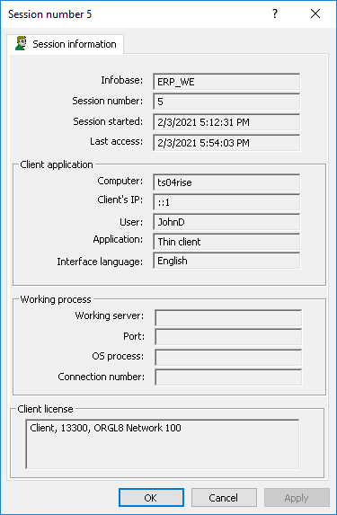 Fig. 57. Session properties
The dialog box of session properties contains the following information (all session properties are not editable, the table is ordered by the indicator name):
| Indicator | Description |
|---|---|
| Client IP | IP of the client application that started the session. IP address
is obtained:
|
| Infobase | Name of the infobase used to open the session. |
| Client license | Indicates a client license to be used by this session and its characteristics. For more details on the generated string, see License description string format. |
| Computer | Network name of the computer running the client application that initiated creation of the session. The computer name will be empty if the session is created by a web client, thin client connected via a web server, or web service. |
| Session start | Time of session creation. |
| Session number | Session number. |
| Connection number | Number of the connection established to this session. |
| User | Name of the infobase user. |
| Port | Number of the network port of the working process servicing this connection. |
| Last call | Time of the last activity of the session. |
| Application | Client application start mode (see Connection types). |
| OS process | Process number of the working server (in terms of the operating system) that is processing this session. |
| Working server | Name of the connected cluster server. |
| Interface language | Localization language of the client application. |
5.2.11.3. Closing Sessions
The administrator can perform the following actions with a session:
-
Terminate the server call for the current session. You can terminate a server call only for the following client applications: thin client, web client, and mobile client.
-
Delete the current session.
You can terminate a server call only if the client session initiates 1C:Enterprise language execution on the server side. Server call termination does not close the client session. The termination itself is performed when executing the next code string in 1C:Enterprise language.
When you delete a session, the current server call is terminated first. After that, the session is deleted. If the session is assigned to a connection upon the session termination, an attempt is made to break the connection (see Terminating a connection).
For the server call termination command (as well as for the session deletion command), you can enter a message that the user will receive after completing the action.
The text specified in this dialog box will be displayed to the user for whom the server call will be terminated. If no text is specified in the dialog box, the user will receive the following standard message: Operation aborted by the administrator.
If there is no server call in the session to be deleted, the session is deleted without displaying any user messages. When a user attempts to perform an action in a client application that used a deleted session, the user gets the following standard error message: Session is not available or has been dropped.
To terminate a server call or close a session, you need the access rights of the server cluster administrator (see Operations with the list of main server administrators).
5.2.12. Operations with the List of Connections
5.2.12.1. General Information
The list of connections can be displayed:
-
For the entire cluster
-
For a working process of a cluster
-
For an infobase
-
For a working process of a cluster server
To display the list of connections for the entire cluster, select a main server in the main server tree and a cluster registered on this server. After that, select and expand the Connections branch.
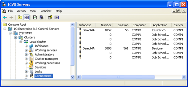 Fig. 58. Cluster connections
To display the list of connections for a working process of a cluster, select a main server, a cluster, and the Working processes branch. After that, select a working process and expand the Connections branch.
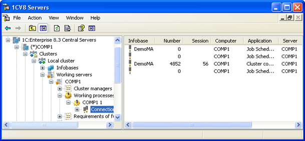 Fig. 59. Working process connections
To display the list of connections for an infobase, select a main server in the main server tree, a cluster, and an infobase. After that, select and expand the Connections branch.
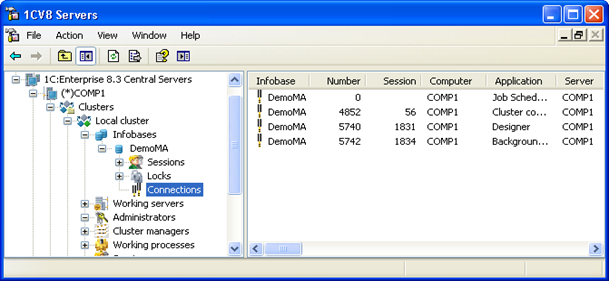 Fig. 60. Infobase connections
To display the list of connections for a working process of a cluster server, select a main server in the main server tree, a cluster, a cluster server, and a working process. After that, select and expand the Connections branch.
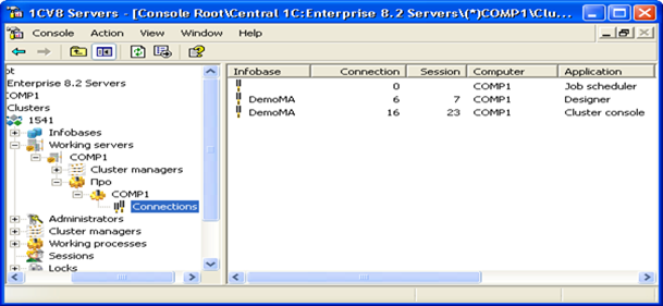 Fig. 61. Working process connections
Connections are not displayed in the main server tree. The properties field displays a list of connections that contains the following information (the table is ordered by the indicator name):
| Indicator | Description |
|---|---|
| Infobase | Name of the connected infobase. This field is empty for service connections. |
| Computer | Network name of the computer that established the connection. |
| Connection start | Time when this connection was established. |
| Server port | Number of the network port of the working process servicing this connection. |
| Application | Identifier of the application that uses this connection (see Connection types). |
| Session | Session number associated with the connection. |
| Server | Name of the connected cluster server. |
| Connection | Connection number. Number of each new infobase connection is incremented by 1. A new connection can only have number 1 assigned if no connections were established to the infobase previously. Number 0 is only assigned to service connections not associated with any infobase. Therefore, both in file and client/server modes, connections are numbered starting from 1 only after all clients, including scheduled and background jobs, disconnect from the infobase. |
If the list of connections is open for an infobase, additional columns are displayed in the properties field, allowing you to quickly analyze database locks. These properties are described in the next section.
5.2.12.2. Viewing Connection Properties
To view connection properties, select a connection in the connection list and execute the Properties context menu command or the same main menu command of the utility.
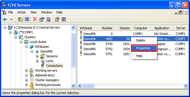 Fig. 62. Infobase connection list
This will open the dialog box of connection properties.
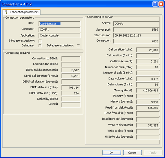 Fig. 63. Connection properties
The dialog box of connection properties contains the following information (all connection properties are not editable, the table is ordered by the indicator name):
| Indicator | Description |
|---|---|
| Database | Indicates that the connection is established with a database. |
| DBMS call duration (5 min) | Total duration of DBMS calls in completed server calls in the last 5 minutes (in seconds). |
| DBMS call duration (total) | Total duration of DBMS calls in completed server calls since the client connection was established (in seconds). |
| DBMS call duration (current) | Total duration of DBMS calls since the current incomplete server call was initiated (in seconds). |
| Call time (5 min) | Total duration of server calls completed by this connection in the last five minutes (in seconds). |
| Call time (total) | Total duration of completed server calls since the client connection was established (in seconds). |
| Call time (current) | Current execution time of the current incomplete server call. |
| Service call time (5 min) * | Total running time of all cluster services in completed server calls in the last 5 minutes (in seconds). |
| Service call time (total) * | Total running time of all cluster services in completed server calls since the client connection was established (in seconds). |
| Service call time (current) * | Running time of the cluster service in the current incomplete server call (in seconds). Name of the service is specified in the Current service property. |
| Locked | User name (connection number), which is displayed if a process is waiting for a transaction lock to be released. |
| DBMS locked | ID of the process that locked the process. |
| Write to disk (5 min) | Amount of data written to the hard drive by completed server calls of this connection in the last 5 minutes (in bytes). |
| Write to disk (total) | Amount of data written to the hard drive by completed server calls of this connection since it was established (in bytes). |
| Write to disk (current) | Amount of data written to a hard drive since the beginning of the current incomplete server call (in bytes). |
| DBMS captured | Duration of database server access at the moment of opening the properties dialog box. It is displayed if the connection currently performs a database call. |
| Exclusive infobase lock | Indicates that an exclusive infobase lock is enabled. |
| Number of calls (5 min) | Total number of completed server calls made by this connection in the last five minutes. |
| Number of calls (total) | Total number of completed server calls made by this connection since it was established. |
| Computer | Name of the computer that established the connection. |
| Exclusively | Indicates that an exclusive infobase mode is enabled. |
| Connection start | Time when the connection was established. |
| Amount of data (5 min) | Amount of data sent and received in completed server calls in the last five minutes (in bytes). |
| Amount of data (total) | Amount of data sent and received in completed server calls since the client connection was established (in bytes). |
| DBMS data (5 min) | Amount of data sent over this client connection between 1C:Enterprise server and the database server in completed server calls in the last 5 minutes (in bytes). |
| DBMS data (total) | Amount of data sent over this client connection between 1C:Enterprise server and the database server in completed server calls since the client connection was established (in bytes). |
| Memory (5 min) | Amount of RAM used for completed server calls in the last 5 minutes (in bytes). |
| Memory (total) | Amount of RAM used for completed server calls since this client connection was established (in bytes). |
| Memory (current) | Amount of RAM used since the current incomplete server call was initiated (in bytes). |
| User | User on whose behalf this connection is established. |
| Server port | Network port of the server used for the connection. |
| Application | Name of the application (see 2.2.4.2. Connection Types) that established the connection to the infobase. |
| Server | Name of the server to which you are connected. |
| Connection | ID of the current connection. |
| DBMS connection | ID of the database server process. It is displayed if the connection currently performs a database call. |
| Current service * | Name of the service that is currently running. If the column is empty, it means that no cluster services are running currently. |
| Read from disk (5 min) | Amount of data read from a hard drive by completed server calls of this connection in the last 5 minutes (in bytes). |
| Read from disk (total) | Amount of data read from the hard drive by completed server calls of this connection since it was established (in bytes). |
| Read from disk (current) | Amount of data read from a hard drive since the current incomplete server call was initiated (in bytes). |
The * character marks the indicators that are available only when the list of infobase connections is displayed, and is not displayed in the properties of a specific connection.
5.2.12.3. Terminating a Connection
To terminate a connection, select the connection in the connection list and execute the Delete context menu command or the same main menu command of the utility.
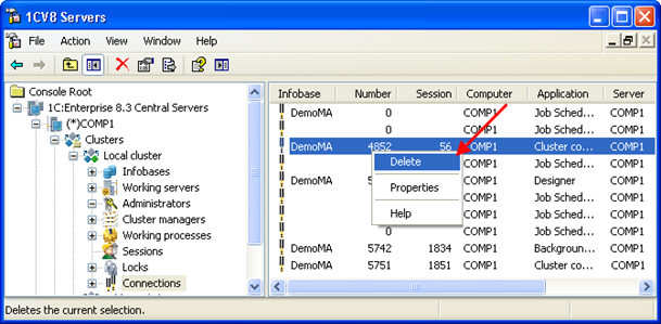 Fig. 64. Deleting a connection
If a large query to a Microsoft SQL Server database, IBM DB2, or Oracle Database is in progress, 1C:Enterprise server attempts to terminate the connection. The attempt succeeds if the user who is connecting to the database server has the appropriate rights. For more information about the required database user rights, see the documentation for the DBMS you are using. If the connection is terminated successfully, the user will receive the following message: The session is terminated by the administrator. PostgreSQL database connections cannot be terminated. Any termination attempts will have no effect.
If the client runs code on 1C:Enterprise server, 1C:Enterprise server will attempt to disconnect the client application from the server. To terminate a connection, you need the access rights of the server cluster administrator (see Operations with the list of main server administrators) and the infobase administrator. If the connection is terminated successfully, the user will receive the following message: The session is terminated by the administrator.
Connection cannot be terminated while 1C:Enterprise server is performing a client call and only one 1C:Enterprise language code line is being executed (except for DBMS calls). For example, a connection cannot be terminated when a long call to a COM object method or an HTTP call is made from code in 1C:Enterprise language.
5.2.13. Operations with the List of Locks
The list of locks can be displayed:
-
For the entire cluster (all locks or by connections)
-
For an infobase (all locks or by connections)
To display the list of locks for the entire cluster, select a main server in the main server tree and a cluster registered on this server. After that, select and expand the Locks branch.
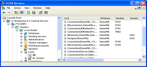 Fig. 65. List of cluster locks
If you then select the All branch, a list of all cluster locks will be displayed.
You can also expand the By sessions branch and select a session. The list of locks for the selected session will be displayed.
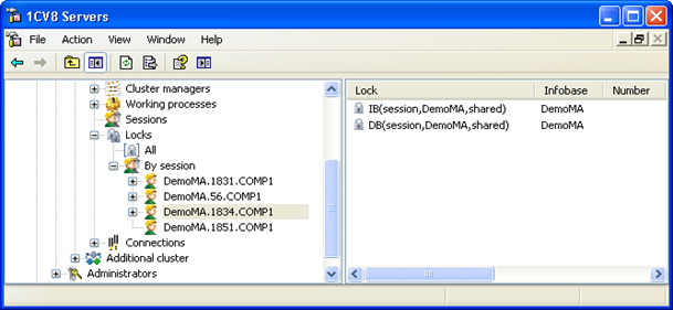 Fig. 66. List of cluster locks by session
To display the list of locks for an infobase, select a main server in the main server tree, a cluster, and an infobase. After that, select and expand the Locks branch.
If you then select the All branch, a list of all locks for this infobase will be displayed.
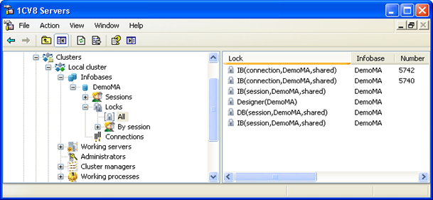 Fig. 67. List of all locks
You can also expand the By sessions branch and select a session. The list of locks for the selected session will be displayed.
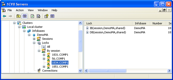 Fig. 68. List of locks by session
If you view the list of locks for a connection, the main server tree will contain a list of connections. Each connection is identified by the number and name of the user's computer.
The properties field displays a list of locks that contains the following information:
- Lock
- Contains lock type presentation and basic lock parameters. The following lock types are supported:
-
Infobase locks:
-
Database. 1C:Enterprise database lock. Parameters:
-
Lock source (session or connection)
-
Infobase name
-
Shared or exclusive
-
If the infobase is shared, this parameter contains information about parameters of the locked area in the format of the /Z parameter of the startup command line of the client application. If a background job removes the exclusive lock of the parent session, the parent session number is specified in this parameter in the >>SessionNumber format, and the locked area parameters are specified by the following parameter.
-
-
Infobase. Infobase lock. Parameters:
-
Lock source (session or connection)
-
Infobase name
-
Shared or exclusive
-
-
Designer. Exclusive Designer lock. Parameters:
- Infobase name
-
-
Database object. Exclusive 1C:Enterprise object lock. Parameters:
- Infobase name
-
Cluster locks:
-
Cluster manager. Activity of a cluster manager process. Parameters:
-
Server name
-
Ports used by the cluster manager process
-
-
Working process. Activity of 1C:Enterprise working process. Parameters:
-
Server name
-
Ports used by the working process of the cluster
-
-
Connection. TCP connection to a working process of a cluster or a scheduled job. Parameters:
-
Name of the server context (can match the infobase name)
-
Computer name and ID of the application that established the connection
-
Infobase names and connection numbers if the connection is associated with any infobases
-
-
- Infobase
- Name of the locked infobase. Empty if the lock is not applied to an infobase.
- Connection
- Infobase connection number. It can be empty if:
-
No infobase is locked.
-
Lock source is a session not assigned to any connection.
- Session
- Number of the session where the lock was applied. It can be empty if:
-
No infobase is locked.
-
Lock source is a connection with no sessions assigned to it.
- Computer
- Name of the client computer used to enable the lock. Empty if the lock source is a server-side process.
- Application
- Name of the client application that enabled the lock. Empty if the lock source is a server-side process.
- Server
- Name of the server of the working process responsible for the lock. Empty if the lock source is a server-side process or a session not assigned to any connection.
- Server port
- Network port of the working process responsible for the lock. Empty if the lock source is a server-side process or a session not assigned to any connection.
- Locked on
- Time when the lock was enabled.
5.2.14. Operations with the List of Security Profiles
To display the list of infobases registered in a cluster, select a server in the main server tree and a cluster registered on this server. After that, select and expand the Security profiles branch.
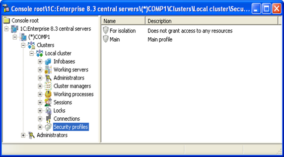 Fig. 69. Security profile list
The main server tree contains a list of cluster security profiles. Each security profile is identified by a name. The properties field displays a list of security profiles of the selected cluster. The list contains names and descriptions of all profiles.
5.2.14.1. Adding Profiles
To add a security profile to the cluster, select a main server in the main server tree and a cluster registered on this server. After that, right-click Security profiles and then click Create – Security profile or execute the same main menu command of the utility.
This will open the dialog box of security profile properties.
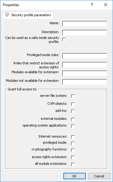 Fig. 70. New security profile
You need to enter the following data in the dialog box fields:
- Name
- Security profile name. The name must be unique per cluster.
- Description
- Arbitrary description of the security profile.
- Can be used as a safe mode security profile.
- Indicates that the name of this profile can be specified as a value of the SafeMode parameter of the SetSafeMode() global context method, the Create() and Connect() methods of the external data processor manager, the Create() and Connect() methods of the external report manager. Also, it indicates that the name can result from the SafeMode() global context function.
- Privileged mode roles
- Allows you to assign roles (separated by ;) to be used when privileged mode is enabled if the privileged mode check box is cleared. For more information on the parameter, see Privileged mode.
- Roles that restrict extension of access rights:
- Allows you to specify roles (separated by ;) that prevent extension of access rights of an extended configuration from the extension.
- Modules available for extension:
- Contains a list of modules that can be extended with extensions. For more information on the parameter, see Extending all configuration modules.
- Modules not available for extension:
- Contains a list of modules that cannot be extended with extensions. For more information on the parameter, see Extending all configuration modules.
- To server file system:
- Defines whether file resources of the computer running 1C:Enterprise server can be accessed from the application. For more information on the parameter, see Server file system resources.
- To COM objects:
- Defines whether the application and COM objects of the computer running 1C:Enterprise server can interact. This parameter has no effect for servers running on Linux. For more information on the parameter, see Server COM objects.
- To add-ins:
- Defines whether the application can interact with add-ins on the 1C:Enterprise server side. For more information on the parameter, see Add-ins.
- To external modules:
- Defines whether the application can use external modules (external reports, data processors, and configuration extensions), the Execute() operator, and the Eval() function.
- To OS applications:
- Defines whether the operating system applications are available for the application on the 1C:Enterprise server side. The list of applications depends on the operating system running 1C:Enterprise server. For more information on the parameter, see OS applications.
- To Internet resources:
- Defines whether the application code executed on 1C:Enterprise server can interact with Internet resources. For more information on the parameter, see Internet resources.
- To privileged mode:
- Defines the access right verification mode (and applicable data access restrictions) if the current session is managed by a security profile. For more information about the checkbox, see Privileged mode.
- To cryptographic functions:
- Defines whether you can use cryptographic features in the application code executed on 1C:Enterprise server.
- To access rights extension:
- Defines whether access rights of the main configuration can be extended for any extended configuration object.
- To all module extensions:
- Defines whether all server configuration modules can be extended using any extension. For more information on the parameter, see Extending all configuration modules.
5.2.14.2. Viewing and Editing Profile Settings
To view or edit security profile parameters, select a profile in the list of cluster security profiles and execute the Properties context menu command or the same main menu command of the utility.
This will open the dialog box of security profile properties.
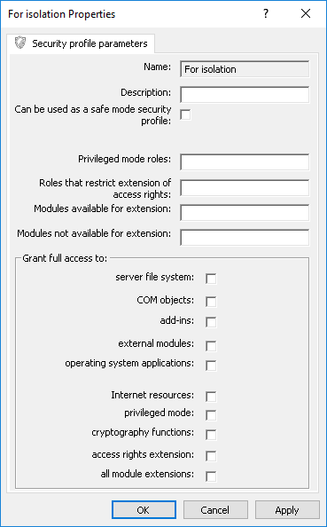 Fig. 71. Security profile properties
Some profile parameters allow you to create exceptions from general restrictions. For example, you can deny access to all directories in the server file system, except for specific directories included in the list of exceptions.
To create an exception from any security profile restriction, right-click an item subordinate to a virtual directory and then click Create – Item you want to create. For example: Create – Virtual directory.
This will open a window that displays the Description property that describes the item being created. For other parameters, see the corresponding section of the general description of the security profile.
5.2.14.3. Deleting Profiles
To delete a security profile, select the profile in the list of security profiles and execute the Delete context menu command or the same main menu command of the utility.
5.2.15. Operations with Resource Usage Management Functionality
5.2.15.1. Resource Consumption Counters
5.2.15.2. General Information
Resource consumption counters are designed to collect and accumulate system performance information. Each counter has a name, a description, and a set of properties that describe the accumulated information.
Information accumulated by the counters can be displayed in the cluster console and can be used by the resource consumption limiting functionality. The resource consumption limiting functionality restricts user actions based on data from the counters.
The counter accumulates information for a single server call or for a specified time period. Use the Registration period property to set a counter mode:
-
Server call. In this case, all parameters that the counter accumulates use the current server call data. Each session that makes a server call is a separate instance of the counter.
-
Custom value. In this case, information is accumulated for a period specified in the Registration period property. A sliding window of the specified size is used to accumulate data. Indicators are not divided by sessions. All sessions are accumulated within one counter.
The counter accumulates the following information:
-
Time spent on the following actions:
-
Server calls. Time spent from the start to the end of a server call in milliseconds. It is generated based on the Call time value in the session properties.
-
CPU usage time. CPU time spent to execute a server call in milliseconds. It is generated based on the CPU usage time value in the session properties.
-
DBMS call time. Time spent on a DBMS call in milliseconds. It is generated based on the DBMS call duration value in the session properties.
-
Service call time.Time spent on the operation of cluster services in milliseconds. Based on the Service call time value in the session properties.
-
-
Amount of data processed during the measurement:
-
Memory. RAM volume currently occupied by a session in bytes. This indicator always shows the current value. Based on the Memory (total) value in the session properties.
-
Read. Amount of data read from a hard drive in bytes. It is generated based on the Read value in the session properties.
-
Write. Amount of data written to a hard drive in bytes. It is generated based on the Write value in the session properties.
-
DBMS data. Amount of data sent and received when operating with the DBMS in bytes. Based on the DBMS data value in the session properties.
-
-
Quantitative indicators:
-
Number of calls. Number of server calls. It is generated based on the Number of calls value in the session properties.
-
Number of active sessions. Current number of active sessions.
-
Number of sessions. Total number of sessions per measurement period. It includes both active and closed sessions.
-
Depending on the data collection duration, different session properties may be used to calculate the indicators:
-
When calculating data per server call, a session property with the (current) suffix is used as the initial information. For example, to calculate the duration of a server call, the Call time (current) property is used.
-
When calculating data per time period, the difference between the total value of the indicator at the end and at the beginning of the period is used. To calculate the Server calls value for a period, the Call time (total) value at the beginning of the period is subtracted from the Call time (total) value at the end of the period.
- Session properties (see Viewing session properties).
5.2.15.3. Viewing and Editing Counter Parameters
To create a resource consumption counter, right-click Resource consumption counters in the cluster console and then click Create – Resource consumption counter. To edit counter parameters, right-click the required counter in the list and select Properties.
In both cases, a window with counter parameters will open. When editing an existing counter, the Name property is not editable.
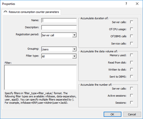 Fig. 72. Resource consumption counter
The Name and Description properties are used to identify and describe the counter. The Registration period property describes how long the counter will collect data. Each counter can be created in the context of a certain property, meaning that the number of counter instances created is equal to the number of unique values for this property. The Grouping property allows you to specify a counter property to be used when creating a new instance:
-
Users. Counter will separately accumulate information on sessions operating on behalf of various 1C:Enterprise users.
-
Data separation. Counter will separately accumulate information on sessions operating with different data areas.
If the Grouping value is changed, the counter is cleared and all its instances are deleted. After that, the counter starts accumulating new values according to the new grouping. Changing other counter properties does not clear the counter.
In the Filter and Filter type fields, you can define how to filter the sessions whose properties will be used by the counter. In the Filter field, specify required filter values. You can set filters:
-
By infobase (the infobase parameter).
-
By values of separators that describe a data area (the data-separation parameter). Values of separators that describe a data area are defined in the same way as the /Z parameter of the startup command line of the client application.
-
By username (the user parameter).
-
By ID of the application using the session (the appID parameter). Value of this parameter matches the value of the InfobaseConnection.ApplicationName property.
-
By security profile (the safe-mode-profile-name parameter). To filter data by default security profile, leave the field name blank, for example: safe-mode-profile-name=;.
-
By safe mode activation status (the safe-mode parameter). There are two possible status values: on for enabled safe mode and off for disabled safe mode.
The parameter value can be compared for equality (operator =) or for inequality (operator <>). Some filter conditions can be combined "by AND". "|" operator is used to group conditions "by OR". For example:
infobase=IB; user<>Admin; user<>Manager; safe-mode-profile-name=profile | infobase<>IB; safe-mode=onwill be interpreted as follows:
-
This filter has the following two conditions:
-
First condition: Infobase is equal to IB AND user is not equal to Admin AND user is not equal to Manager AND security profile is equal to profile.
-
Second condition: Infobase is not equal to IB AND safe mode is enabled.
-
-
The first condition and the second condition are combined "by OR".
The Filter type property allows you to specify the filter mode in general: equality or inequality.
5.2.15.4. Deleting One or All Counter Instances
You can delete an entire counter or its specific instance. Both operations are performed in a similar manner: select an item that you need to delete, right-click it, and select Delete.
To delete the entire counter, select the counter in the cluster object tree or in the list of counters (select Resource consumption counters in the object tree).
To delete a specific instance, select a counter, open its instance list, and select an instance from the list.
5.2.15.5. Resource Consumption Limits
5.2.15.6. General Information
Different client applications create different load on the server cluster. This load may adversely affect the overall performance of the cluster. For example, if a user decides to get all records for all goods for the entire lifetime of the infobase, such report most likely will completely paralyze the entire system for a long period of time. In addition, such report might cause an abnormal termination due to exhaustion of available RAM or other similar reasons.
To detect such actions, you can create resource consumption counters in a server cluster. You can also automatically restrict operations performed by the users and data areas (depending on the counter grouping) that exceed the resource consumption threshold. The resource consumption limiting functionality controls such restrictions. The functionality interacts with resource consumption counters.
You can use the limiting functionality to set required actions for sessions that exceed a specified threshold for one or several counter parameters. The following options are available:
-
Close session. Terminate the server call and close the session.
-
Terminate server call. Terminate the server call without closing the session.
-
Decrease thread priority. Decrease the priority of a thread that is performing the current server call.
-
None. Record the threshold violation in the technological log, but do not restrict execution of the server call.
Regardless of the selected option, the ATTN event is added to the technological log.
The limiting functionality operates as follows:
-
Create one or more counters with desired characteristics.
-
For each counter, you can create a rule that specifies threshold values for any counter parameters. Once such threshold is exceeded, a restrictive action is performed. The restrictive action is only performed when all thresholds are exceeded at the same time. However, only the first threshold violation is recorded in the technological log.
-
The counter and rules take effect.
Please keep in mind that for counters set up to analyze indicators for a period of time, executing restrictions of the Close session and Terminate server call types will prohibit any new server calls until the counter indicators fall below their thresholds.
5.2.15.7. Viewing and Editing Limit Settings
To set up a new resource consumption limit, right-click Resource consumption limits in the cluster console and then click Create – Resource consumption limit. To edit limit parameters, right-click the required limit in the list and select Properties.
In both cases, a window with limit parameters will open. When you edit an existing limit, you cannot change the Name property.
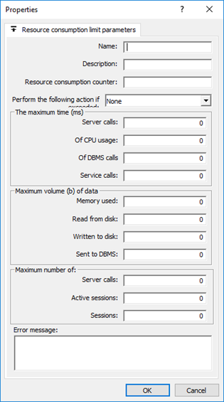 Fig. 73. Resource consumption limit parameters
The Name and Description properties are used to identify and describe each resource consumption limit. The Resource consumption counter property contains a name of the counter to be used for this limit. You can enter a counter name using a keyboard or select it from a drop-down list that contains the current counter list. The Resource consumption counter property is required. Use the Action upon exceeding property to set an action that will be performed if the current counter value exceeds the limits specified in this window.
The Maximum number of... groups are used to specify values that trigger actions specified in the Action upon exceeding property when they are exceeded. The values are described with the parameters of the resource consumption counter.
Text in the Error message property will be displayed to the user if the server call or session is terminated.
- Resource consumption counters (see Resource consumption counters).
5.2.15.8. Deleting Limits
To delete a resource consumption limit, select it in the list and execute the Delete context menu command or the same main menu command of the utility.
5.3. Server Cluster Administration Software
5.3.1. Using 1C:Enterprise Language to Access Server Clusters
5.3.1.1. Via COM Connection
The API of 1C:Enterprise server cluster administration is described in the Syntax Assistant. To find the description, go to Integration and administration tools – COM connection manager – Server cluster administration.
You can use this feature only if 1C:Enterprise application administering the cluster:
-
Runs on Windows.
-
Has the same version as the administered server cluster.
Two objects are used for server cluster administration: ConnectServerAgent and ConnectWorkingProcess.
To get ConnectServerAgent, use the ConnectAgent() method of the COM connector object:
COMConnector = New COMObject("V83.COMConnector");
ConnectServerAgent = COMConnector.ConnectAgent ("TestSrv");
Server agent connection is used to:
-
Authenticate, add, delete, and get a list of main server administrators and cluster administrators.
-
Create, delete, and get a list of clusters.
-
Create, delete, and get a list of servers.
-
Create, delete, and get a list of working processes of a cluster.
-
Get a list of cluster services.
-
Get a list of infobase sessions.
-
Get a list of cluster connections.
-
Get a list of infobase connections.
-
Get a list of infobases registered in the cluster.
-
Get a list of cluster locks.
-
Get other information.
To get ConnectWorkingProcess, use the ConnectWorkingProcess() method of the COM connector object:
COMConnector = New COMObject("V83.COMConnector");
ConnectWorkingProcess = COMConnect.ConnectWorkingProcess ("TestSrv: 1562");
Working process connection is used to:
-
Authenticate infobase users.
-
Create, delete, and get a list of infobases registered in the cluster.
-
Get a list of infobase connections.
-
Disconnect an infobase.
-
Connect to an infobase (COM connection).
-
Get other information.
5.3.1.2. Via Server Cluster Administration Server
The API of 1C:Enterprise server cluster administration using the administration server is described in the Syntax Assistant. To find the description, go to Integration and administration tools – 1C:Enterprise server administration.
1C:Enterprise allows you to administer any number of 1C:Enterprise server clusters using the 1C:Enterprise server cluster administration server (ras).
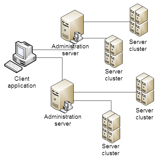 Fig. 74. Administration via the administration server
As you can see in the picture, the overall administration algorithm looks as follows:
-
A clients application is connected to any administration server.
-
The selected administration server establishes connection to required server clusters.
The object model designed for administration server operations is similar to the command-line utility (rac) designed for the same purpose.
Considering this, administration is possible if:
-
1C:Enterprise application administering a server cluster can run on Linux, macOS, and Windows.
-
Versions of 1C:Enterprise application (administering a server cluster), administration server, and server cluster do not have to match (considering administration server specifics).
-
Control is possible both from the client application and server application sides.
-
1C:Enterprise client application where administrative operations are performed can process file infobases and be disconnected from the administered server cluster in terms of data.
The general procedure is as follows:
-
Connection to an administration server is established.
-
An administrator (if any) of the main server of the cluster is authenticated.
-
The list of clusters available on selected main server is generated.
-
An administrator (if any) of a specific cluster is authenticated.
-
Administrative actions can be performed now.
You can find the most basic example of API usage below:
Agent = New ServerAdministration("localhost", 1545);
Agent.Authenticate();
Clusters = Agent.GetClusters();
For Each Cluster In Clusters Do
  Cluster.Authenticate();
  Infobases = Cluster.GetInfoBases();
  For Each InfoBase In InfoBases Do
    Message(InfoBase.Name + ", " + InfoBase.Description);
  EndDo;
EndDo;- Administration server of server cluster (see Server cluster administration server).
5.3.2. Server Cluster Administration Server
5.3.2.1. General Information
To administer a server cluster, you can use a cluster administration server. It includes the server (ras) and the command line utility (rac) used for server cluster management.
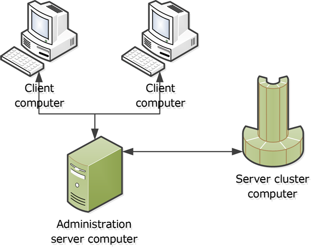 Fig. 75. Administration server
The server cluster and the administration server (ras) must have the same version. If you use the command line utility (rac), consider the following restrictions:
-
The command line utility (rac) version 8.3.1 or 8.3.2 can only be used with the administration server (ras) version 8.3.1 or 8.3.2.
-
The command line utility (rac) version 8.3.3 or 8.3.4 can only be used with the administration server (ras) version 8.3.3 or 8.3.4.
-
The command line utility (rac) versions 8.3.5 - 8.3.8 can only be used with the administration server (ras) versions 8.3.5 - 8.3.8.
-
The command line utility (rac) version 8.3.9 and later can only be used with the administration server (ras) version 8.3.9 and later. If you use the command line utility whose version is earlier than the administration server version, only features implemented in the platform corresponding to the command line utility version are available. If you need a specific feature, use the command line utility version where this feature is implemented (considering the restrictions mentioned above).
Both the administration server and the command line utility can work in any supported OS. Multiple administration servers can be connected to a single server cluster at the same time. An administration server can be connected to one server agent only.
An administration server (ras) can run as an application, as a Windows service, or as a Linux daemon. The general procedure is as follows:
-
The administration server is started as an application or as a service/daemon.
-
The command line utility connects to the administration server to perform required actions.
-
For the duration of operations, the administration server is connected to the server cluster. It is disconnected from the cluster after the operations are completed. Therefore, there is no need to stop the administration server during scheduled server cluster operations associated with cluster stop or restart. Changing the server cluster version is an exception. In this case, you need to change the administration server version for it to match to the server cluster version.
The administration server and the administration utility are installed together with the 1C:Enterprise server (see Installing system components).
For interaction between the administration server and the administration utility, network port 1545 is used. This can be redefined using the --port parameter of the administration server startup command line (ras).
The administration utility allows you to perform all operations required to administer a server cluster. However, the following features are not supported:
- OS authentication for server cluster administrators, working server administrators, and infobase administrators.
The administration utility (rac) gets all necessary parameters from the command line and sends information to the standard output stream (stdout). If successful, the return code of the utility is equal to 0. Otherwise, the return code is non-zero and an error message is sent to the standard error stream (stderr).
The utility operation result is a description of one or several data objects (for example, a list of infobase servers registered in a cluster) presented in a table:
<Parameter name> : <Parameter value>Successfully completed cluster item creation commands (except for administrators) send the ID of the created item to the stream in the format specified above.
Strings that allow arbitrary characters are displayed in double quotes. Already existing double quotes in such strings are duplicated.
Dates are displayed in XML format (https://www.w3.org/TR/2012/REC-xmlschema11-2-20120405/#dateTime).
For more information about parameters of the administration server (ras) or the administration utility (rac), run the corresponding executable file with the help command-line parameter:
ras help
rac help
The ITS disk also provides a Java archive package that allows accessing the administrator server from a Java program without using the console administration utility (http://its.1c.ru/db/metod8dev#content:4985:hdoc).
5.3.2.2. Starting the Administration Server
5.3.2.3. On Windows
In application mode
To start the administration server in application mode, use the following command line:
ras cluster --port=<port> --monitor-address=<address> --monitor-base=<location> --monitor-port=<port> <host[:port]>In service mode
To start the administration server in service mode, you need to register the administration server as a service. You can perform this operation using a batch file that uses the Windows sc utility.
Example of starting the command file (administrator rights are required):
register-ras 8.3.24.1005.3.2.4. On Linux
In application mode
To start the administration server in application mode, use the following command line:
./ras cluster --port=<port> --monitor-address=<address> --monitor-base=<location> --monitor-port=<port> <host[:port]>In daemon mode
To start the administration server (ras) in daemon mode, you need to start the administration server using a special command-line switch:
./ras cluster --daemon --port=<port> --monitor-address=<address> --monitor-base=<location> --monitor-port=<port> <host[:port]>5.4. Binary Data Storage
5.4.1. General Information
Infobases often store various large-size data: documents, goods images, and so on. This data can be required for the information system operation or used as service data. Large data is usually stored in an infobase in attributes of the ValueStorage type. It is a convenient way to store data as the database contains all information required for different operations. At the same time, you can store such data on a disk drive separately from the infobase. In this case, you need to manually implement this storage API and its backup.
1C:Enterprise provides a compromise and allows you to store large data in a binary data storage. With this option, you can store data on a disk drive (built-in storage) or in an external storage accessible over Amazon S3 (S3 storage). You also receive certain benefits from the platform, for example: a) transparency in managing data no matter where it is located and b) an API for external storage administration, including backup and restoration. A good thing about the binary data storage is that you do not need to modify your code to use it. You can access data in the same way: use the value of the ValueStorage type and write/read this value into the object attribute.
In addition to using the storage, 1C:Enterprise allows you to manage the data size threshold, which will write the data to the binary data storage when exceeded, and whether to use a binary data storage for each ValueStorage type attribute. The use of a binary data storage by an attribute can be unconditional or conditional. In the second case, the use of a binary data storage can depend not only on the size of stored data, but also on some other parameters.
Consider that whether data will be available in the ValueStorage attributes when you transfer the infobase to another computer or a server cluster depends on the storage used in the transferred infobase:
-
Built-in storage. To make sure that you will have access to data, transfer the binary data storage with the infobase. If you do not transfer it, data will be lost and you will no longer be able to use it.
-
S3 storage. In this case, you need to grant access to the storage API from a new infobase position. Access option depends on which external storage you use to store binary data. If access is not provided, data will be lost. For S3 storage, 1C:Enterprise does not support multipart upload (part of S3 protocol). The size of the file you can place in the S3 storage is determined by the limits on the size of the file transmitted in one fragment (set on the S3 server), but cannot exceed 4 GB.
When setting up the binary data storage, keep in mind an important feature of writing data to the storage. If a value of a configuration object attribute is placed in a binary data storage, data in the storage will be written whenever a specific instance of this configuration object is written. Writing to the binary data storage does not depend on whether the data to store is changed or not. If a built-in storage is used as a binary data storage, data duplication will be eliminated using object deduplication (see Deduplicating data in the storage). If an S3 storage is used as a binary data storage, you can eliminate object duplication using backup or storage cleanup (see Clearing data). Before these operations, an S3 storage will store more data than can be expected.
If more than one binary data storage is connected to the infobase, you can specify what storage will contain data of what attribute of what object. To set it up, use the standard function (in the system's client application) or 1C:Enterprise language.
You can apply the binary data storage only if the following is used:
-
Server infobase
-
The 64-bit version of the server cluster is used.
5.4.2. Setting Up Data Placement
5.4.2.1. General Information
The binary data storage offers various tools: enabling/disabling block binary data storage (in previous compatibility modes), managing the storage location of specific attribute data, and managing data of each storage.
You can set up operating parameters of the binary data storage at the metadata level (in Designer mode) and at the running application level (in 1C:Enterprise mode, using 1C:Enterprise language). Settings made in 1C:Enterprise mode have priority over the settings made in Designer. Remember it when it comes to determining whether an attribute can be written to a binary data storage, or which binary data storage the attribute value will be written to. An attribute value will only be written to the binary data storage if all conditions that determine whether an attribute can be written to the storage and that are described in this section are met. If the conditions are not met, the attribute value will be written to the corresponding infobase.
5.4.2.2. Binary Data Storage
In client/server infobases, binary data (values of the ValueStorage type attributes) is stored in a special database system table. Binary data is stored in blocks. Each block has a maximum size of 448 MB. This table contains data larger than 2 KB. If the data size exceeds 448 MB, several records will be allocated to store such data (the number of records is a multiple of the block size). Such storage is not used in file infobases (all data is stored in separate tables of "their" objects). When restoring an infobase from a DT file, the data will be placed in tables of "their" configuration objects. Block storage allows you to bypass the restrictions of various DBMS on the maximum size of binary data (BLOB, Binary Large Object) that can be stored in the DBMS table field.
Let's focus on the block data placement management. If 1C:Enterprise platform version 8.3.26 and compatibility mode above Version 8.3.26 (with the Do not use value for version 8.3.26) are used, a special system table is always used and this is the only operation mode. If 1C:Enterprise platform version 8.3.26 and compatibility mode below Version 8.3.26 (for example, Version 8.3.25, Version 8.3.24, and preceding values) are used, the Block binary data storage mode property becomes available in configuration properties. When you change the property value, the behavior will be as follows:
-
The value is set to Use: the existing attributes are not transferred to the system table. Binary data is written to the system table after block storage is enabled.
-
The value is set to Do not use: data from the system table is transferred to tables of "their" configuration objects.
The 1C:Enterprise system provides an interface for managing modes of writing and reading in the binary data storage. This interface is formed by the following methods: GetBinaryDataStorageDataCopiesPlacementMode() andSetBinaryDataStorageDataCopiesPlacementMode(). These methods operate with the BinaryDataStorageDataCopiesPlacementMode system enumeration values. The values of this enumeration determine how the platform will write and read binary data:
| Value | Description |
|---|---|
| DataPlacementToStorageAndToDatabaseOnInaccessibleStorage | Data is placed in a binary data storage. If writing to the binary data storage is impossible, binary data will be placed in the infobase. In this mode, if the binary data storage is not available, you can read binary data only if it is in the infobase. |
| DataPlacementToStorageOnly | Data is written to a binary data storage. When reading, data is first read from the storage, and in case of a reading error, it is read from the infobase. |
| DataCopiesPlacementToStorageOnWritingToDatabase | Data is written to a binary data storage and an infobase. When reading, data is first read from the storage, and in case of a reading error, it is read from the infobase. It is used to provide fault-tolerant data storage in the infobase using a binary data storage as a quick access cache. |
| DataCopiesPlacementToStorageOnReadingFromDatabase | Data is written to an infobase. When reading, data is first read from the binary data storage, and in case of a reading error, it is read from the infobase. If there is no data in the binary data storage, it is synchronously copied there from the infobase. In this case, the binary data storage is used as a quick access cache, so data is placed in the binary data storage after the first reading. |
5.4.2.3. Attribute Storage Management
You can manage data placement in a binary data storage using several related features. Each subsequent feature requires enabling the previous one:
-
A common feature for the entire infobase is setting a data size threshold. If the value in the attribute is greater than this value, it will be stored in the binary data storage. For more information, see Storage management.
-
Unconditional enabling or disabling of the storage for each attribute with the ValueStorage type. To do this, set the Use storage in binary data storage property to Use for the necessary attributes. In this case, all the data that gets into this attribute (and exceeds the record size threshold) will be placed in the binary data storage.
-
Conditional enabling or disabling of the storage for each attribute with the ValueStorage type. To do this, in addition to enabling the Use storage in binary data storage property, specify a value of the Storage usage field in binary data storage property. In this case, attribute data will be transferred to the appropriate binary data storage if all the following conditions are met:
-
The attribute specified in the Storage usage field in binary data storage property is set to True.
-
The value size exceeds the threshold value.
-
Remember that conditional storage management is performed for each data item for which conditional placement is enabled. In other words, an attribute value will be written to the binary data storage if, when writing the object that contains an attribute (for example, catalog), the attribute which controls writing is set to True.
5.4.2.4. Managing Data for a Specific Storage
If more than one binary data storage is connected to the infobase, you can specify what data to store in which storage. This allows you to keep data of different configuration objects in different storages. For this separation, use either the standard Binary data storage management function or 1C:Enterprise language. When distributing the load across storages, remember that one attribute can only be stored in one binary data storage. Let's take a closer look at how to distribute data across storages using 1C:Enterprise language.
To manage what data is stored in a particular binary data storage, use the SetStoredDataContent()/GetStoredDataContent() methods of the binary data storage manager or the StoredDataContent property for the external binary data storage manager. To use the SetStoredDataContent() method, set exclusive access to the infobase. All of these tools operate with the value of the BinaryDataStorageDataContent type, which is a collection of the BinaryDataStorageDataContentItem type objects. Each attribute is described by a single value of the BinaryDataStorageDataContentItem type with the following properties:
-
Metadata. Stores a reference to a metadata object that describes a configuration object attribute that can be placed in a binary data storage. This can be an object attribute, a register resource, or a constant with the ValueStorage type.
-
Storage. The property indicates that it is required to store an attribute in the binary data storage. It is presented by the value of the BinaryDataStorageLocationUse system enumeration.
So, programmatic management of stored attributes comes to generating the BinaryDataStorageDataContent collection, which is installed in the appropriate binary data storage manager. Take into account that one attribute cannot be stored in multiple binary data storages. If it happens, an exception will be thrown when setting the stored data.
If no "personal" storage is set for a configuration object attribute, the attribute value will be written to the default binary data storage. To set a binary data storage as a default one, use the standard Binary data storage management data processor or 1C:Enterprise language. You can set a binary data storage as a default one only if data writing is allowed for this storage.
The following methods are used to manage the default storage:
-
For a built-in binary data storage: the SetUsingAsDefaultStorage()/GetUsingAsDefaultStorage() methods of the binary data storage manager. To set a default binary data storage, you need exclusive access to the infobase.
-
For an external binary data storage: the DefaultStorage property of the external binary data storage manager.
There can be only one default storage. Monitor it manually when implementing the interface for interactive selection of a default storage.
5.4.2.5. Identifying the Used Storage to Write Binary Data
When writing a value of the ValueStorage type, the location to write the value to is determined as follows:
-
If a composition item of any binary data storage is connected to the attribute, the rule specified in the composition item is applied.
-
Otherwise, the default binary data storage is used if it is available for writing.
-
In all other cases, attributes are written to the infobase.
5.4.3. Storage Management
5.4.3.1. General Information
To start using the binary data storage:
-
Configure the server cluster for the internal storage or create S3 storage.
-
Enable the functionality in the application.
When you configure a server cluster, set the functionality management rule that will place the appropriate cluster service on the required production server. If the cluster runs on one server, you do not need to set the rule. After the cluster is configured and restarted, set up an application. You can apply these settings using 1C:Enterprise language or the respective standard data processor.
Create S3 storage according to the rules of a company or service owner that provides you with a storage and access to it via the Internet. The S3 storage can be configured to impose a limit on the transferred file volume and on the number of requests to the storage per second. To work around the first limitation, 1C:Enterprise uses multipart import and export. With multipart import and export, files are imported or exported in fixed-size fragments, which are combined into a single file after all parts are transferred. When transferring a file to the S3 storage, the fragment size is selected automatically. When receiving a file from the S3 storage, the fragment size is fixed (100 MB) and cannot be changed. If the S3 storage imposes a limit on the number of requests per second, the platform determines this and attempts to execute the request several times. In total, up to 4 retries are performed, with a gradually increasing interval between retries. The pause between two consecutive requests will not exceed 20 seconds.
When you use the binary data storage, make sure you set a data size threshold. Once this value is exceeded, data is sent to the storage. This value is set for each connected storage. If the size of the data that you want to save to the infobase (in serialized form) exceeds the value set as a threshold, the data will be automatically saved to a particular binary data storage. In this case, the infobase will have a flag indicating that the data is placed in the storage. If the data size is less than the threshold, the data is saved only to the infobase.
When an object whose attribute values are stored in a binary data storage is deleted from the infobase, the data is not deleted in the storage, but only marked for deletion (the same way as in the infobase). Marked objects are deleted when backing up the binary data storage. You can also use a special method to clear the binary data storage of the objects marked for deletion.
-
Backing up a binary data storage (see Backup).
-
Clearing binary data storage objects marked for deletion (see Clearing data).
5.4.3.2. Built-in Storage
5.4.3.3. Operating from 1C:Enterprise Language
To call the binary data storage API, use the BinaryDataStorage global context property. This property provides access to the manager of the binary data storage. So, calling API methods will look as follows: BinaryDataStorage.CalledMethodName(). For simplicity, the name of the global context property will be omitted in the following text.
Before you start using the storage, make sure the current 1C:Enterprise platform version supports the binary data storage. You can do it using the GetBinaryDataStorageAvailability() method. If the storage is available, you can start using it. The availability of the binary data warehouse is determined as follows:
-
If the Compatibility mode configuration property is set to one of the values from Version 8.3.10 to Version 8.3.21 (including both values), the method result depends on the value of the Binary data storage mode configuration property:
-
Use: the method returns True.
-
Do not use: the method returns False.
-
-
If the Compatibility mode configuration property is set to Version 8.3.22 and later, the method always returns True.
-
In file infobases, the binary data storage is always unavailable.
To enable the binary data storage, use the SetBinaryDataStorageUseMode() method. To enable the mode, exclusive infobase mode is required. To find out the current mode of the binary data storage, use the GetBinaryDataStorageUseMode() method. To manage the threshold of data you save to the storage, use the GetMinWriteDataSize()/SetMinWriteDataSize() methods.
You can manage data saving to the storage without disabling it. To do it, use the GetBinaryDataStorageReadWriteMode() or SetBinaryDataStorageReadWriteMode() method. With this method, you can switch the storage to read-only mode. In this case, new data is saved to the database instead of the storage. However, data already written to the storage can still be received and remain available to users.
5.4.3.4. Deduplicating Data in the Storage
The storage can store duplicate data. Such data can take up a lot of storage space. To make sure data is not duplicated, use the deduplication tool. The tool searches for and deletes duplicates in the storage. The logical storage state remain unchanged. The tool optimizes the space occupied by the storage.
Deduplication happens:
-
When you save a new object to the storage. In this case, data is considered mapped if there is a complete binary map.
-
In background mode. In this mode, the algorithm tries to find mapping parts in some file types. Besides deduplicating the whole files, file parts can be deduplicated for Microsoft Compound File Binary File Format files that store Microsoft Office files up to version 2023 and files with PDF documents.
With background deduplication, you can only deduplicate saved data, and only after more than 2 months have passed since the last access to the data. That means that only objects that are not used can be deduplicated.
Deduplication happens automatically and does not have management tools.
To get more information on the number of mapping objects, use the BinaryDataStorageInformation object (see Getting information on the storage).
5.4.3.5. Getting Information on the Storage
You can get information on the current state of the binary data storage. To do this, use the BinaryDataStorage.GetInformation() method. As a result, you will receive the BinaryDataStorageInformation object that has the following information:
-
LastClearingDate. Date and time of the last storage clearing from obsolete data.
-
DeduplicatedItemsCount. Number of deleted stored duplicates.
-
DeletedItemsCount. Number of objects that are deleted logically (marked for deletion) but occupy the disk space.
-
StoredItemsCount. Number of objects in the storage excluding the deleted ones.
-
DeletedDataSize. Size of obsolete objects in the storage in bytes.
-
StoredDataSize. Size of objects stored in the storage in bytes.
-
StoredDataSizeOnDisk. Size that the storage occupies on the disk drive in bytes.
5.4.3.6. Changing the Binary Data Storage Location
A directory with data of the binary data storage is located in a cluster data directory on a production server selected for the Binary data storage service cluster service. To find out how to specify a directory with service data, as well as how to edit this directory, see Changing the location of directories with service data. You may need to transfer the data directory not only if the directory is physically moved within the same production server. It may be required, for example, if the binary data storage service is transferred to another production server using a functionality assignment rule.
5.4.3.7. S3 Storage
5.4.3.8. Operating from 1C:Enterprise Language
To access the S3 binary data storage interface, use the BinaryDataExternalStorages global context property (you can use the "external storage" or "external binary data storage" terms). This property provides access to the manager of the external binary data storage. So, calling API methods will look as follows: BinaryDataExternalStorages.CalledMethodName(). For simplicity, the name of the global context property will be omitted in the following text.
To access the external binary data storage, use the following objects:
-
BinaryDataExternalStorageConnectionParameters. The object describes parameters for connecting to S3 storage.
-
BinaryDataExternalStorageAccessParameters. The object describes the data set required to get access to the external binary data storage.
As parameters for connecting to S3 storage, provide the endpoint URL (the BinaryDataExternalStorageConnectionParameters.URL property) and the specified URL type (the BinaryDataExternalStorageConnectionParameters.URLType property). The URLType describes the style in which you need to set the endpoint URL to a container (bucket) from your S3 storage provider:
-
The virtual-hosted-style is a path to the container in which the container name is considered when generating the domain name along with other provider parameters. In this case, the ID of a particular resource generates the path in the domain. To set this style, use the ExternalBinaryDataStorageURLType.S3VirtualHost system enumeration.
-
Path-style. With this style, the container name is considered when generating the path in the domain along with the resource ID and the domain address is fixed. To set this style, use the ExternalBinaryDataStorageURLType.S3HostWithBucketInPath system enumeration.
If the S3 storage provider limits the number of containers for each user, you can create a storage inside an existing container. To do this, specify the folder inside the existing container using the BinaryDataExternalStorageConnectionParameters.Directory property. The full address of the external storage will be generated as the URL + "/" + Directory expression result.
Once you define the parameters for connecting to S3 storage, determine the parameters for accessing the storage. These parameters are determined by the following parameters:
-
Access ID. This is a public UUID of the S3 storage client. In storage terms, it can be called "Access Key ID". Specify this ID in the BinaryDataExternalStorageAccessParameters.AccessID property.
-
Secret key. This is a private part of the ID to access container data. To get access, you need to have an access ID and a secret key. In storage terms, a secret key can be called "Secret Access Key". Specify this ID in the BinaryDataExternalStorageAccessParameters.SecretKey property.
-
Storage location region. You can use this property when getting access to a storage, for example, when the storage depends on the region. Specify this ID in the BinaryDataExternalStorageAccessParameters.Region property.
If you know the connection and access parameters to S3 storage, you can add this storage to the list of used external binary data storages. To do this, use the Add() method of the manager of external binary data storages. The manager receives the name and access parameters of the external storage you create. To start using S3 storage, save the created object using the Save() method.
You can manage the rest of the parameters via the object of the BinaryDataExternalStorageManager type. You can find the name and connection parameters of the storage in the Name, ConnectionParameters, and AccessParameters properties of this object.
Set a data size threshold using the MinWriteDataSize property. Once this value is exceeded, data will be saved to the storage. To enable or disable the storage, use the ReadWriteMode property. The property is similar to the GetBinaryDataStorageReadWriteMode()/SetBinaryDataStorageReadWriteMode() methods of the built-in storage.
To clear the binary data storage from deleted objects and to reduce the size of the disk space occupied by the storage, use the LastClearingDate property and the ClearUnusedSpaceByUniversalDate() method. For more information, see Clearing data.
5.4.4. Clearing Data
5.4.4.1. General Information
When you delete data in the infobase, related (obsolete) data in the binary data storage is marked as deleted but not deleted. As a result, the storage space does not change. It leads to an excessive consumption of the disk space on the server or in an external storage. So, deleting data from the storage does not reduce the size occupied by this storage.
To actually delete obsolete data, use a special API that depends on the used storage.
To clear a binary data storage:
-
Back up a 1C:Enterprise infobase.
-
Back up a binary data storage.
-
Clear the storage from obsolete data and specify a date that precedes the start of the binary data storage backup.
In this section, you will find out how to use the API.
5.4.4.2. Built-in Storage
To delete obsolete storage data, use the ClearUnusedSpaceByUniversalDate() method of the BinaryDataStorageManager object. The date that is used as a border is passed as a method parameter. All data that is marked for deletion earlier than the specified date will be deleted.
You can clear data after you back up storage data. The threshold point in time is passed as a parameter of the backup generation method.
- Built-in storage backup (see Built-in storage).
5.4.4.3. S3 Storage
To delete obsolete storage data, use the ClearUnusedSpaceByUniversalDate() method of the BinaryDataExternalStorageManager object. The date that is used as a border is passed as a method parameter. All data that is marked for deletion earlier than the specified date will be deleted.
5.4.5. Backup
5.4.5.1. General Information
Like an infobase, binary data storage requires backup. The storage backup methods depend on which storage you use with the infobase. This section describes methods to back up binary data storage depending on the storage kind.
5.4.5.2. Built-in Storage
Let us review the methods required to create a built-in storage backup. Backup can be full or differential. Full backup (as the name implies) transfers all the storage files to a backup file. To perform full backup, use the CreateFullBackup() method. As a result, a file whose name is specified by the method parameter will be generated. The file will be a backup. We recommend that you specify a file with the .sbf extension (Storage Backup, Full) as the standard data processor for managing binary data storage will prompt you to select a file with this extension by default.
The obvious disadvantage of a full backup is that it occupies more storage space and takes more time to be created. If you do not update the binary data storage often, you can perform differential backup instead. A differential backup will contain only changes that you made to the data since the start of the previous full backup. In other words, the differential backup will contain all the data that did not get to the full backup specified as a base for determining differences. Note that you cannot perform differential backup without at least one full backup. To perform differential backup, use the CreateDifferentialBackup() method. The name of the file with a backup is passed as a method parameter. We recommend that you specify a file with the .sbf extension (Storage Backup, Differential) as the standard data processor for managing binary data storage will prompt you to select a file with this extension by default.
You can restore data from the backup depending on the backup method:
-
To restore data from a full backup, you only need one file (the backup). To do it, use the LoadFullBackup() method.
-
To restore data from a differential backup, you need a full backup file and a differential backup file. Note that the differential backup file must be based on the full backup file used for data restoring. To restore data, use the LoadDifferentialBackup() method.
To determine the point in time the system will consider the full backup start, use the GetBackupCreationUniversalDate() method. Specify a full backup file for the method. You can use this point in time to specify a point in time in the method for clearing the storage from outdated data as a threshold.
With 1C:Enterprise, after the backup, you can clear the storage once and compact the binary data storage. You can do it if the value of the UnversalDateForClearing optional parameter is specified when you call the CreateFullBackup() and CreateDifferentialBackup() methods.
If one of the modes (DataCopiesPlacementToStorageOnWritingToDatabase or DataCopiesPlacementToStorageOnReadingFromDatabase) is set to operate with the binary data storage using the SetBinaryDataStorageDataCopiesPlacementMode() method, the minimum acceptable backup option is to back up an infobase without a binary data storage. When restoring the infobase, it will be enough to restore only the infobase. However, even with these settings, we recommend that you back up and restore the binary data storage upon each backup.
When you restore a binary data storage from a backup, all "deletion marks" of binary data storage items are removed as backing up and restoring a binary data storage has nothing to do with the state of the infobase that is connected to this storage. To minimize possible data loss when restoring storage data, all the data is restored.
-
Clearing storage from obsolete data (see Clearing data).
-
Binary data storage (see Binary data storage).
5.4.5.3. S3 Storage
Back up S3 storage using the service owner tools of such storage. Note that when you transfer S3 storage to another service owner, you need to transfer data from one service owner container to the container of another service owner. Otherwise, data in the infobase will be unavailable.
5.4.6. Administering Binary Data Storage
5.4.6.1. General Information
To manage the binary data storage, use the following:
-
Designer dialog box (available via Main menu – Administration – Binary data storage management).
-
Standard function (in 1C:Enterprise mode).
-
Cluster console dialog box.
The first two tools are identical. They only differ in the place where they are called and executed. Both tools are available only for the 64-bit client/server infobase.
This section describes the Designer tools. For more information about the standard function, see the help. For the features of the cluster console dialog box, see Operations with the list of binary data storages.
5.4.6.2. Storage List
Clicking Main menu – Administration – Binary data storage management opens a form with a list of binary data storages to which the current infobase is connected.
To create a connection to a new storage, click Add.
In the dialog box that opens, select the configuration storage type: a built-in server cluster storage (Built-in storage) or S3 storage (External storage over S3 protocol and External storage over S3 protocol (virtual host)). For S3 storage, specify the connection data. You can get it from the storage provider.
To connect to the selected storage, click OK. It will be available in read-only mode.
To delete a storage, click Delete. In this case, the system will not use this storage, but its contents will not be deleted.
To configure an external binary data storage, click Edit. These actions are discussed in the next section.
5.4.6.3. Storage Actions
In the storage settings dialog box, you can perform various storage administration tasks. Each task has its own tab.
- General settings
- On this tab, you can enable the storage writing mode (the Allow writing radio button). As a result, new data whose size exceeds the one specified in the Minimal data size (bytes) field will get into the storage.
- Backup creation
- On this tab, you can back up the selected binary data storage. Both full and differential backups can be performed. To create a differential backup, specify a file with a full backup.
For more details on backups, see Backup.
- Restore from backup
- On this tab, you can restore the binary data storage from a previously created backup. You can restore it both from a full or differential backup. To restore from a differential backup, specify a file with a full backup.
For more details on backups, see Backup.
- Storage information
- This tab displays information about the current parameters of the selected binary data storage.
For the parameter details, see Getting information on the storage.
- Clear storage
- On this tab, you can clear the binary data storage.
For more information, see Clearing data.
5.5. DBMS Administration
5.5.1. General Information
In 1C:Enterprise applications, you can perform some administrative actions that do not affect the application performance or the data structure presentation used by 1C:Enterprise. This also includes restructuring the infobase and saving the changes after the restructuring is completed. In this section, you can read about these actions.
5.5.2. Using Encryption at DBMS Level
Available for DBMS:
-
Microsoft SQL Server 2008 or later.
-
Oracle Database.
5.5.3. Server Cluster Support
A server cluster is a group of computers connected via high-speed communication channels that serves as a single hardware resource for users.
Available for DBMS:
-
IBM Db2.
-
Microsoft SQL Server;
-
Oracle Database.
-
PostgreSQL
5.5.4. Using Data Compression at DBMS Level.
Available for DBMS:
- Oracle Database (only through compressed tablespace).
5.5.5. Managing Tablespaces
5.5.5.1. Support for Changing the Location of Predefined Tablespaces
Available for DBMS:
-
IBM Db2
-
Oracle Database
-
PostgreSQL
Predefined tablespaces:
-
IBM Db2:
-
For indexes: V81C_INDEXSPACE.
-
For data: V81C_LARGESPACE.
-
for LOB: V81C_LOBSPACE.
-
Temporary user tablespace: V81C_USERTEMP.
-
Temporary system tablespace: V81C_SYSTEMPBP.
-
-
Oracle Database:
-
For indexes: V81C_INDEX.
-
For data: v81c_data.
-
For LOB: V81C_LOB.
-
Temporary tablespace: V81C_TEMP.
-
-
PostgreSQL:
-
For indexes: V81C_INDEX.
-
For data: v81c_data.
-
Temporary tablespace: custom name that is specified in the postgresql.conf configuration file.
-
5.5.5.2. Managing User Tablespaces
5.5.5.3. General Information
You can use tablespaces to organize the storage space of various database objects, for example, tables and indexes. To manage tablespaces, you can use the following tools:
-
Tablespace usage mode configuration property.
-
Database tablespace management standard function.
-
Infobase testing and correction feature.
The feature is available for all supported database management systems:
-
IBM Db2
-
Microsoft SQL Server
-
Oracle Database
-
PostgreSQL
User tablespaces belong to a specific database. Tablespace settings are not transferred between databases when you export an infobase to a dt-file and import it back to another DBMS.
To create user tablespaces, grant the following rights to the user to be connected to the DBMS:
-
IBM Db2: SYSCTRL or SYSADM rights.
-
Microsoft SQL Server: ALTER right to the database.
-
Oracle Database: CREATE TABLESPACE and DROP TABLESPACE privileges.
-
PostgreSQL: assign the SUPERUSER role.
User tablespace management is not supported for Data Accelerator and file infobases.
-
Configuration properties.
-
Standard functions.
-
Infobase testing and correction feature.
5.5.5.4. Adding Tablespaces
To add a new tablespace:
-
Enable the use of tablespaces (for Version 8.3.22 or earlier compatibility mode). You can do it in Designer.
-
Run the client application (thin client or web client).
-
Open the standard Database tablespace management function.
-
Create a new tablespace. Note that directories that you specify when creating a tablespace must exist on the computer running the DBMS server at the moment you click Save in the standard function form.
-
Place required tables and indexes in the created tablespaces.
-
Click Save. If the operation is successfully completed, perform the following action.
-
Update the placement of infobase tables via Designer in interactive or batch mode. For that:
-
In interactive mode, use the Verify and repair infobase Designer function and select the Update infobase table placement mode.
-
In batch mode, use the /IBCheckAndRepair command with the -RefreshTableLocation parameter.
-
If the operation is successfully completed, the tablespaces are created and ready for use.
If you need to connect to already created tablespaces, do the following when you add a new tablespace:
-
Find out the exact name of an existing tablespace and the directory where the files of this tablespace are located.
-
Open the standard tablespace management function.
-
Add a new user tablespace and specify:
-
As a name, the name of the existing tablespace.
-
As a path, the directory of the tablespace files.
-
-
Perform the remaining operations to add a tablespace.
5.5.5.5. Deleting Tablespaces
To delete a user tablespace:
-
Open the standard Database tablespace management function.
-
Exclude all tables and indexes from the tablespace you want to delete.
-
Update the placement of infobase tables via Designer in interactive or batch mode. For that:
-
In interactive mode, use the Verify and repair infobase Designer function and select the Update infobase table placement mode.
-
In batch mode, use the /IBCheckAndRepair command with the -RefreshTableLocation parameter.
-
If the operation is successfully completed, the tablespaces are no longer used in the DBMS.
-
Open the standard Database tablespace management function again.
-
Delete unused tablespaces.
5.5.5.6. Using 1C:Enterprise Language
In 1C:Enterprise, you can programmatically manage user tablespaces. To access this API, use the DatabaseTablespaces global context property. It will grant you access to the database tablespace manager. So, calling API methods will look as follows: DatabaseTablespaces.CalledMethodName(). For simplicity, the name of the global context property will be omitted in the following text.
At the moment 1C:Enterprise is started, the current configuration of infobase tablespaces is read. To get this configuration, iterate the collection of existing tablespaces using the For each iterator or the [] operator:
For Each Tablespace In DatabaseTablespaces Do
  Message("Name: " + Tablespace.Name + ", path: " + Tablespace.TablespacePath);
EndDo;
The DatabaseTablespaces collection includes objects of the DatabaseTablespaceManager type. Let us take a closer look at the object. To identify a tablespace, use the Name property. You can find the path to the tablespace files in the TablespacePath property. If you know the tablespace name, you can get the respective tablespace manager using the Find() method of the tablespace manager.
Besides the name and the path, the object that describes a tablespace has two property sets:
-
Current tablespace content. A list of tables and indexes that are currently included in the tablespace. This data is stored in the UsedDataContent and UsedIndexesContent properties.
-
Future tablespace content. A list of tables and indexes that will be transferred to the tablespace after updating the table placement. This data is stored in the ChangedDataContent and ChangedIndexesContent properties.
Each of the specified properties has a value of the DatabaseTablespaceContent type. This type is a collection of objects of the DatabaseTablespaceContentItem type. The DatabaseTablespaceContentItem object contains only one property: Metadata. This property specifies the metadata object whose data tables or indexes will be placed in a particular tablespace. The DatabaseTablespaceContent object is a typical collection with the standard set of management methods.
It is also important to note two more pairs of tablespace manager methods:
-
FindByUsedDataContent() and FindByUsedIndexesContent(). These methods allow you to determine what tablespace has data tables or indexes of a certain configuration object.
-
FindByChangedDataContent() and FindByChangedIndexesContent(). With these methods, you can also find out what tablespace will contain data tables or indexes after updating the table placement.
Let us take a look at how you can add two tablespaces (for data and indexes) for the Goods catalog. The example does not demonstrate any verifications.
Item = New DatabaseTablespaceContentItem;
Item.Metadata = Metadata.Catalogs.Goods;
DataTablespace = DatabaseTablespaces.Add("ExtraData", "d:\data\data-files");
DataTablespace.ChangedDataContent.Add(Item);
DataTablespace.Write();
TablespaceIndex = DatabaseTablespaces.Add("ExtraIndex", "d:\data\index-files");
TablespaceIndex.ChangedIndexesContent.Add(Item);
TablespaceIndex.Write();
After you execute this code in 1C:Enterprise language, update the database table placement manually or in Designer batch mode.
5.5.6. Changing Database File Location
Available for DBMS:
- Microsoft SQL Server
5.5.7. Changing Transaction Log Location
Available for DBMS:
-
IBM Db2
-
Microsoft SQL Server;
-
Oracle Database
-
PostgreSQL
5.5.8. Performing Administrative Tasks
Performing various administrative tasks that do not change the database structure but ensure adequate performance.
Available for DBMS:
-
IBM Db2
-
Microsoft SQL Server;
-
Oracle Database
-
PostgreSQL
Administrative tasks:
-
Integrity check
-
Reindexing
-
Defragmentation
-
Reorganization
-
Backup creation (see Backup in client/server mode)
-
Procedure cache clearing
-
Statistics data collection
Chapter 6. Server Cluster Update
To update an information system running in client/server mode to a new 1C:Enterprise version, perform a number of actions. They can be divided into two categories: preliminary actions and the update itself. The preliminary actions are not time-restricted and can take as much time as necessary. Update the system as quickly as possible so that the system downtime is minimal.
-
Preliminary steps:
-
Get a server cluster distribution package of a version to be updated to.
-
Get a client application distribution package of the same version as the server cluster.
-
Get administrator rights of the computer or computers running 1C:Enterprise server cluster.
-
Get database administrator (DBA) rights to back up infobases.
-
Prepare and place the client application distribution package on a network resource or a web server.
-
Perform acceptance testing of the new 1C:Enterprise version and the used application version. It is required to prevent unexpected changes in the information system operation after updating the production system. To perform acceptance testing, develop a test set that "closes" the automation of critical business processes of each infobase.
-
Prepare command processor scenarios that allow you to quickly update the registration of the server cluster service or perform the required actions to register the automatic server cluster start (for Linux).
-
Install a new version of the 1C:Enterprise server cluster to computers that are a part of the server cluster. For more details on the installation process, see Installing 1C:Enterprise server.
-
-
Update itself. Perform these actions after the preliminary actions are completed. Make sure they take as little time as possible:
-
Lock starting new sessions for all infobases served by the server cluster to be updated.
-
Configure the cluster database backup and perform backups. The company backup policy determines whether to perform backups before updating the server cluster version. To perform a backup, you may need DBA rights. Perform backup operations using DBMS functionality. The execution of all backup operations can follow the scenario of the used command processor or DBMS.
-
This step can be considered a critical section of the update process. The following actions will result in the server cluster running on another version of 1C:Enterprise.
-
Disconnect all users from the infobases of the server cluster to be updated.
-
Stop the server cluster.
-
Start the server cluster update scenarios (batch files) that were prepared at step 1.7. You can also perform the update actions manually. However, the automation tools allow you to minimize the operation execution time and reduce the number of errors. The update must be performed on all computers in the cluster.
-
Start the server cluster.
-
Update infobase publications on one or several web servers. You can update publications either manually (using Designer) or using a scenario file and the webinst utility.
-
Restart one or several web servers where the infobases of the server cluster to be updated are published.
-
-
Unlock starting new sessions for all infobases of the updated cluster.
-
Chapter 7. Deleting Applications
7.1. Deleting a Server Cluster on Linux
7.1.1. Using the Uninstaller
The utility required to delete each version is located in the directory of this version. The utility has a name in the following format: uninstaller-full. Version deletion requires superuser rights (root).
For example, to delete a full installation of 1C:Enterprise version 8.3.24.100 for a 64-bit operating system, run the following command:
sudo /opt/1cv8/x86_64/8.3.24.100/uninstaller-fullWhen you install the application, the uninstallAsRoot utility is installed. You can use the application to simplify the version deletion. If you run this application, the following will happen:
-
The application checks whether you have superuser rights (root).
-
If you do not have them, the acquisition of these rights will be initiated. To get the rights, enter the superuser password in the dialog box opened by the uninstallAsRoot application.
-
If the password is entered, the uninstaller with the superuser rights will be started.
For an experienced user, the uninstallAsRoot application startup is similar to the following command-line option:
sudo ./uninstaller-*.runIn this example, "*" refers to the uninstaller name. For more details on name, see Rules to name distribution files. If you run uninstallAsRoot in a directory that has several run files, the installer whose file name is the first in the search results for files by the "uninstall-*.run" mask will be started.
7.1.2. Using the Package Manager
To uninstall 1C:Enterprise, use the command of the package manager of the used operating system. Version deletion requires superuser rights (root).
If you install the system using the installer, you cannot delete it with the package manager.
7.2. Deleting a Server Cluster on Windows
1C:Enterprise server is deleted by a special program that removes system components from the computer's hard drive and makes changes to the Start menu and Microsoft Windows system information.
You must stop 1C:Enterprise server before deleting it.
To uninstall 1C:Enterprise, follow these steps:
-
Open Windows control panel and click the Programs and features icon.
-
If necessary, click Replace or delete in the opened dialog box.
-
In the list of installed programs, select 1C Enterprise 8.3 (8.3.X.YYY) and click Delete.
You will be asked if you want to uninstall the program. If you confirm, Windows will start uninstalling the selected 1C:Enterprise version from the computer and making the necessary changes to the system information.
Appendix 1. License Description String Format
Full or brief license information can be displayed. In brief license information, working processes or sessions are displayed in a column. Full license information is displayed in the working process properties window or session properties window.
License information has the following format:
Received by, PID, Server, Port, License description, License file nameYou will see different fields depending on the license type (HASP or software one) as well as brief and full license information.
- Received by
- Indicates the license owner:
-
Client. The license is obtained by the client application.
-
Server. The license is obtained by 1C:Enterprise server.
- PID
- Identifier of the OS process that obtained the client license.
Not used in brief license presentation.
- Server
- Name of 1C:Enterprise server that obtained the client license.
Not used in brief license presentation.
Not used if the license is obtained by the client application.
- Port
- Network port number of the server process (rphost or rmngr) that obtained the license.
Not used in brief license presentation.
Not used if the license is obtained by the client application.
- License description
- Contains license source description.
If the license is obtained from a dongle, the license description is as follows:
<Dongle series> <Dongle type> <Number of licenses>Where:
-
Dongle series. A dongle series.
-
Dongle type. One of dongle types:
-
Local. The dongle is plugged in to the computer that obtained the license.
-
Network. The dongle is available on the network via HASP License Manager.
-
-
Number of licenses. The maximum number of licenses available for this dongle.
If the client license is provided using the software licensing system, the license description is as follows:
<Package number> <License type> <Number of licenses>Where:
-
Package number. Registration number of the package with software licenses.
-
License type. Activated license type. For combo packages, it can take two values: 1 (for single-user or server licenses) or a value equal to the Number of licenses field (for multi-user licenses).
-
Number of licenses. The maximum number of licenses available for this license package.
- License file name
- Full name of the software license file whose license was obtained by the working process or session.
Not used in brief license presentation.
Not used for licenses obtained from a dongle.
Examples of client license presentation strings:
Client, 4648, ORGL8 Local 1The license is obtained by a client application whose OS process ID is 4648. The license is obtained from a local dongle.
Client, 3840, ORG8A Network 300The license is obtained by a client application whose OS process ID is 3840. The license is obtained from a network dongle.
Server, 1648, SERVER-1C, 1560, ORG8B Network 500The client license is obtained using the SERVER-1C server running via port 1560. OS process ID of the process that obtained the license is 1648. The license is obtained from a 500-user network dongle.
Server, 1648, SERVER-1C, 1560, ORGL8 Local 1The client license is obtained using the SERVER-1C server running via port 1560. OS process ID of the process that obtained the license is 1648. The license is obtained from a single-user local dongle.
Server 1970, ENSR8 Local 1The server license (for a 32-bit server) is obtained by a working process whose OS process ID is 1970. The dongle is located on the computer running the working process.
Server, 4524, SERVER-1C, 1560, 8000314159 1 1, file://C:/Users/USR1CV8/AppData/Local/1C/1cv8/conf/20100521112156.licThe server license is obtained by a working process of the SERVER-1C server running via port 1560. OS process ID of the process that obtained the license is 4524. The software server license is obtained from the package No. 8000314159. The license file is 20100521112156.lic. It is located in the C:/Users/USR1CV8/AppData/Local/1C/1cv8/conf directory.
Server, 896, SERVER-1C, 1564, 8000453822 20 20, file://C:/Documents and Settings/USR1CV8/Local Settings/Application Data/1C/1cv8/conf/20110812100013.licThe client license is obtained using the SERVER-1C server running via port 1564. OS process ID of the process that obtained the license is 896. The software license is obtained from a 20-user combo package, which is activated as a multi-user license. Package number: 8000453822. The license file is 20110812100013.lic. It is located in the C:/Documents and Settings/USR1CV8/Local Settings/Application Data/1C/1cv8/conf directory.
Appendix 2. Format of the Schedule String for Restarting Working Processes (Cron Format)
The schedule string for restarting working processes of the server cluster is specified in cron format. Cron format contains 6 fields separated by spaces or tab characters. However, 1C:Enterprise uses only the first 5 fields. The field with the command name is not used and is not required.
Each field (numbering from right to left) is responsible for its own schedule item:
| Field number | Description |
|---|---|
| 1 | Minute of the hour. Possible values: from 0 to 59. |
| 2 | Hour of the day. Possible values: from 0 to 23. |
| 3 | Day of the month. Possible values: from 1 to 31. |
| 4 | Month of the year. Possible values: from 1 to 12. |
| 5 | Day of the week. Possible values: from 0 to 6. Sunday is 0, Monday is 1, and so on. |
Each field can take different values:
-
Number.
-
Several numbers separated by "," (comma).
-
Two numbers separated by "-" (hyphen, minus).
-
"*" (multiplication sign, asterisk).
-
"/" (straight slash). This character can end any valid value.
The "*" character means "every". If this character is specified in field 1, the schedule will be triggered every minute.
Specifying a single number means specifying exactly one value. If the value of field 2 is set to 4, it means that the schedule will be triggered every 4th hour of the day.
Specifying a value interval (number-number) means that the schedule will trigger each value of the interval, including the boundaries. For example, 5-10 in field 3 means that the schedule will be triggered in 5th, 6th, 7th, 8th, 9th and 10th day of the month.
Specifying the "/" character after the value indicates the interval of executing this field. For example, */10 in field 1 means that the schedule will be triggered every 10 minutes. 0-23/2 in field 2 means that the schedule will be triggered every second hour of the day: at 12:00 a.m., 2 a.m., 4 a.m., 6 a.m., 8 a.m., 10 a.m., 12 a.m., 14 p.m., 16 p.m., 18 p.m., 20 p.m., and 22 p.m.
To facilitate schedule line generation, you can use, for example, this website: https://crontab.guru/. On this website, avoid schedules that are marked as Non standard! May not work with every cron. and various meta characters in the schedule, for example, @yearly, and so on.
Here are some examples of schedules with explanation:
| Example | Description |
|---|---|
| * * * * * | Every minute. |
| */10 * * * * | Every 10th minute (0, 10, 20 and so on). |
| 0 0 * * * | Every day at 12 a.m. (midnight). |
| 0 3 * * 6 | Every Saturday at 3 a.m. |
| 0 3 * * 1-5 | From Monday to Friday at 3 a.m. |
| 0 3 1 * * | At 3 a.m. every first day of the month. |
| 0 3 */4 * * | At 3 a.m. every fourth day. |