1C:Enterprise Development Tools
- Chapter 1. Getting Started
- Features
- Installation, Update
- Installation Guide
- Choosing an Installation Package
- System Requirements
- Installation in the Graphical Interface
- Installing from the Command Line
- Installing Software for Debugging Desktop Applications
- Thin Client on a Local Network, File-Based Mode
- Thin Client over the Internet, File Mode
- Thin Client on a Local Network, Client-Server Mode
- Thin Client over the Internet, Client-Server Mode
- Web Client, File-Based Mode
- Web Client, Client-Server Mode
- Thick Client, File-Based Mode
- Thick Client, Client-Server Mode
- First Launch
- Updating
- Removing
- Using the Offline Installation Package
- Installation Guide
- Usage Examples
- Extending with Plug-ins
- New in Version 2024.1
- If You Encounter a Problem
- Chapter 2. Using with the 1C:EDT Start Launch and Update Application
- Chapter 3. 1C:EDT Configuration
- Chapter 4. Projects
- Navigator Panel
- Properties Panel
- Configuration Project
- Configuration Extension Project
- External Reports and Data Processors Project
- Mobile Applications
- Installing the Platform and Selecting the Development Method
- Creating a New Mobile Application Project
- Debugging a Mobile Application on Android OS Using Android Debug Bridge
- Debugging a Mobile Application Through a Web Server
- Launching the Developer Platform and Application
- Building a Mobile Application
- Tasks
- The Result of Desktop Application Development
- Chapter 5. Configuration
- Chapter 6. Infobases
- Chapter 7. Web Servers
- Chapter 8. Writing Code
- Chapter 9. Launching 1C:Enterprise Client Applications
- Chapter 10. Debugging Applications
- Debugging Setup
- Configuring Debugging for Client Applications
- Configuring Debugging for Various Components
- Debug Targets Connection
- Starting the Server Cluster in Debug Mode
- Enabling Debugging in the Infobase Publication on a Web Server
- Enabling Debugging for External Connections
- Creating a Launch Configuration for Debugging on a Specified Port
- Debugging Scenarios
- Debug Panel
- Console Panel
- Debugging Setup
- Chapter 11. Team Development and the Git Version Control System
- Usage Examples
- Creating a Remote Repository on GitHub and Placing the Configuration in It
- Cloning a Remote Repository for Collaboration
- Importing a Project from the 1C Repository
- Forking a Repository on GitHub
- Fixing an Error in the Main Branch of the Remote Repository
- Creating a Project in a Feature Branch and Merging It into the Main Branch of the Remote Repository
- Resolving Conflicts When Merging Modules
- Hiding Language Errors of the Main Branch
- Setting Up Team Development
- Transition to Development in 1C:EDT
- Using Git When Editing Projects
- Graphical Interface and Command Line
- Repositories
- Remote Repositories
- Changes
- Branching
- Tags
- Submodules
- Development Panel
- Usage Examples
- Chapter 12. Automating Testing with Deployment of Changes to Working Infobases
- Chapter 13. Command Line Interface
- Chapter 14. Reference Information
- Copyright Information
- New Sections
- Known Issues and Their Solutions
- Platform Support Installation Error
- Infobase Creation Failed
- Error Publishing to Web Server Cause: Access Error to the File httpd.conf
- A Platform Version of at Least ... Is Required to Interact with the Configuration
- After Execution, No Users With Administrative Privileges Would Remain!
- Performance Degradation in Disk Operations
Chapter 1. Getting Started
First Steps
Install 1C:EDT
Launch for the First Time
Usage Examples
Projects
Writing Code
Help
Switching from Designer
Gradual Transition to Development in 1C:EDT
Developer Tools
Command Line Interface
Team Development and the Git Version Control System
Infobases
Web Servers
Overview of Features
1C:EDT is a modern, extensible application development environment. It is built on top of the free integrated development environment for modular cross-platform applications Eclipse, which is widely used by developers around the world.
1C:EDT supports the key principles of application development on the 1C:Enterprise Platform. Contains a wide range of development automation tools that make programming faster and more convenient, and also allows you to extend the functionality of development tools using the plugin technology.
Cross-platform
1C:EDT allows you to develop on all operating systems that the 1C:Enterprise Platform supports: Windows, Linux, and macOS.
The section Installation, Update provides recommendations for performing typical operations (installation, launch, removal) in different operating systems.
User Interface
The 1C:EDT interface consists of panels of the same type developer tools that surround the editor. The composition and arrangement of elements can be customized to suit your needs.
Coding Assistance
-
Contextual Hint A contextual hint helps you write and edit program text. With its help, you can speed up text entry and avoid errors and typos.
The context hint not only suggests an appropriate identifier, method, or property to insert, but also shows syntax information for the element you’re about to use.
Using context hints, comment templates for custom procedures and functions can be inserted. The syntax hint will suggest comments formatted this way, just as it does for 1C:Enterprise language procedures and functions.
Event handlers can also be created using contextual hints, or using the context menu command.
-
Refactoring Refactoring tools help you rename variables, extract local variables, and any procedures.
Full-text search is used when performing refactoring. You can view all planned changes and compare module texts "before" and "after" within the same window, considering the semantics of the 1C:Enterprise language.
-
On-the-fly Configuration Validation Configuration Validation checks modules on the fly, right in the process of editing. Lines containing errors and warnings are marked with markers. Hovering the cursor over a marker, you can read the description of the problem.
Clicking on a warning or error marker, you can automatically fix the error. If 1C:EDT has correction options, it will offer them to you.
-
Launch and Debug Configurations
You can use different versions of the 1C:Enterprise Platform and different infobases to run and debug projects. 1C:EDT saves all necessary parameters in launch configurations and debug configurations. You simply launch one of them.
The main parameters required to run are:
-
The project that contains the application configuration
-
The infobase that will be used for running this configuration
-
The 1C:Enterprise client application that will be launched
Debugging
During debugging, you can use a wide range of features implemented in various 1C:EDT tools:
-
You can see the results of integrated debugging directly in the module text, including the values of the module's local variables.
-
By hovering the cursor over identifiers, you can see their values in a tooltip. Complex values are shown as a tree
-
You can view values both in the panel Variables and in the panel Values. The Values panel conveniently displays the contents of collections.
-
It is possible to modify variable values directly during debugging.
-
Breakpoints can be exported and imported for example, to ask a colleague to fix errors that occur at these points
-
You can run applications on a remote computer for debugging, connect debugging to an application already running there.
Performance Measurement
Performance measurement allows you to estimate the speed of the entire application or part of it running within any debug target.
Infobase Management
All operations with infobases can be run within 1C:EDT. It uses the same list of infobases that the 1C:Enterprise Platform uses. By changing this list in 1C:EDT, you will see the same changes when you launch 1C:Enterprise client applications.
1C:EDT, compared to 1C:Enterprise, provides a number of additional features. For example, fast publishing a configuration to a web server or directly deleting a file-based infobase on disk.
Web Server Management
1C:EDT allows you to manage all web servers that you might need to run and debug applications. When 1C:EDT starts, it automatically finds all web servers installed on the computer, as well as all publications that have been made on them.
You can not only manage servers, but also copy publications from one server to another. If not all web servers were found automatically, you can add them to the list manually.
-
Built-in Web Server for Debugging Mobile Applications For debugging mobile applications, 1C:EDT already contains its own built-in web server. You do not need to install a separate web server.
-
Integration with the 1C:Link Service 1C:EDT is integrated with the 1C:Link service. It can be used to publish infobases and debug them using the web client.
1C:EDT supports this web server on Windows OS (without conditions) and on Linux OS, provided that the Apache web server is additionally installed independently.
-
Tasks
A task is an action or objective that needs to be completed. Tasks can be used to plan the scope of upcoming activities. When creating tasks, you can specify their priority level.
It is possible to link tasks to specific lines of modules. This way, you not only leave yourself a reminder of what needs to be done, but you can also quickly navigate to the place where these actions need to be run.
ER Diagrams
You can use the ER Diagram tool to analyze the structure of a business application in the form of an ER diagram. The ER model represents the data structure of an application as a set of configuration objects that have attributes. These objects interact with each other through relationships.
Git Integration
1C:EDT supports the Git version control system by default. You can connect to existing repositories and create your own. This makes it possible to version and store copies of only your own developments, or to collaborate on the project as a team.
Command Line Interface
You can use the command-line interface. It is convenient for automating the development process: validating projects, converting to XML configuration uploads and back, and other routine operations.
Extending with Plug-ins
Since 1C:EDT is developed using Eclipse technologies, you can extend its capabilities with plugins. For example, you can install a plugin that will allow you to quickly connect to various DBMSs, view the structure of their data, and execute queries.
You can also create your own plugins to add new functionality to 1C:EDT.
The standard 1C:EDT distribution already includes three plugins that are developed by the community under an open license.
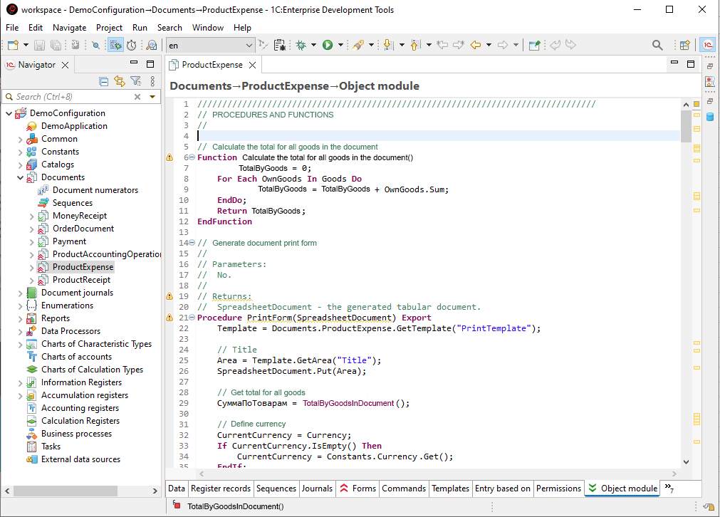
1C:EDT Interface
The entire 1C:EDT interface consists of elements of the same type, which can be customized to your needs in the same way.
All activity takes place in the main window, where multiple perspectives can be open at the same time. The screenshot below shows the 1C:Enterprise perspective.
Perspectives
In the main 1C:EDT window, you can open one or more perspectives. A perspective defines which panels and how they will be located in the main window. In addition, a perspective may contain an editor area in which 1C:EDT opens editors used in that perspective.
Thus, each perspective provides a set of functionality for solving a specific range of tasks or for dealing with a certain type of resource.
Only one perspective is active at a time, but you can quickly switch to other open perspectives.
For example, the 1C:Enterprise perspective combines the panels that you typically use to edit the configuration object tree and modules. And the Debug perspective contains panels that allow you to debug programs in the 1C:Enterprise language. When you're using the main window, you can quickly switch between the open perspectives.
In addition, perspectives manage the composition of the main menu and the composition of the Main Window Command Bar. You can change the composition and arrangement of panels in a perspective. You can save a perspective that you have customized for yourself so that you can use it again next time.
Editors
1C:EDT contains a significant number of editors. Each of them allows you to edit your part of the application. For example, the 1C:Enterprise Language Editor, the form editor, several editors designed for setting up permissions, the configuration object editor, and so on.
The perspective has a special editor area in which 1C:EDT opens the windows of all editors. Each editor window has its own tab. This allows you to quickly switch from one editor to another without closing them. At the same time, you see the rest of the perspective's tools (panels) and can use them together with the editors.
For example, the ER Diagram panel is used in conjunction with the 1C:Enterprise Language Editor. When you navigate through the module in the editor, the procedure in the body of which you are located is highlighted in this panel. And vice versa, when you click on a procedure in the ER Diagram panel, the definition of this procedure opens in the editor.
Panels
Each perspective tool is a panel. In perspective, each panel has its own location on the screen. You can drag panels, collapse them, expand them to full screen, move them outside the main window to a second monitor. The arrangement of panel elements is remembered as well as their composition.
Each panel serves as an individual development tool. For example, the Infobases panel allows you to add, remove infobases, load configurations into them, and unload them. The Navigator panel allows you to modify the structure of the application, add and remove configuration objects and their attributes.
Typically, panels are part of a perspective. So, by opening a perspective, you immediately get a set of tools designed to perform a specific task. For example, such perspectives are 1C:Enterprise and Debug.
At the same time, there are panels that are not part of perspectives and are opened as a result of executing commands. For example, when you want to analyze the call hierarchy of a procedure, the Call Hierarchy panel will be opened to show the results. You may need to view the hierarchy both during development and debugging. Therefore, the Call Hierarchy panel is not included in any perspective in advance and opens "on demand".
Despite the fact that the panels are either in the right place or open at the right time, there is also a general list of all panels. Thus, at any time you can open the tool you need from it and even save it as part of any perspective if you need it in this perspective constantly.
This approach allows you to flexibly customize the composition of development tools and their location on the screen.
Command Bars
There are four types of command bars in 1C:EDT:
-
Main Window Command Bar The Main Window Command Bar is located at the top, below the main menu. It contains a common set of commands, which can be supplemented by commands provided by specific perspectives or editors. All commands are grouped into several sections in it. You can drag these sections with the mouse.
-
Command Bars for Panels The second type is the own command bars that exist for panels (for example, for the Navigator, Infobases panels, and so on). They are located next to or below the panel title. Their commands apply only to the contents of the panels.
-
Perspective Panel The third type of panel is the Perspective panel. It can be used to quickly switch between open perspectives. It also has a button that allows you to open a new perspective. Usually the Perspective panel is located in the upper right corner, next to the Main Window Command Bar. But you can drag it to another location.
-
Collapsed Panels Finally, the last type of command bar appears when you collapse a set of panels. When collapsed, they are represented by a small bar located on the left or right side of the screen. This bar contains its own icon for each collapsed panel and a common icon to restore the entire set. By clicking on the icon of a collapsed panel, you can activate it so that it covers the current content of the perspective.
-
Help
Documentation Within 1C:EDT
1C:EDT contains all the necessary reference information. To read it in an individual window, click Help > Help Contents.
The help information is divided into several main sections:
-
1C:Enterprise (Syntax Assistant) Reference for 1C:Enterprise Language Types.
Fastpath: When using in the 1C:Enterprise Language Editor with the help closed, you can quickly open Syntax Assistant by pressing Shift+F1.
-
1C:Enterprise Development Tools Application development documentation.
-
1C:Code style V8 Documentation for the plug-in for developing according to 1C standards and practices for the 1C:Enterprise Platform.
-
1C:SSL support for 1C:EDT Documentation for the plug-in for developing based on the 1C:Library of Standard Subsystems (1C:BSS) library.
-
Workbench User Guide English documentation on the capabilities of the Eclipse platform, the standard elements of which are used by 1C:EDT.
-
EGit Documentation English documentation on using the Git version control system.
-
Eclipse Marketplace User Guide English documentation on using the Eclipse Marketplace web portal.
-
The help system includes a convenient search engine. It allows you to create custom search scopes (to avoid searching through all materials) and bookmark sections you want to return to quickly.
Online Documentation
-
Developer Guide The 1C:EDT online documentation is published on the ITS portal and is available to registered portal users.
-
Plugin Developer Guide The 1C:EDT Plugin Developer Guide documentation describes configuration metadata models, extension points, and services you may need when developing 1C:EDT plug-ins. It also includes a demo plug-in example, which you can use for learning or as a template for creating your own plug-ins.
-
JavaDoc Description (JavaDoc) of 1C:EDT classes. To include them in 1C:EDT, add com.e1c.g5.v8.dt.javadocs to the target platform.
To see the latest information, replace the release number (2023.1) in the following link: https://edt.1c.ru/dev/edt/2023.1/apidocs/.
Technical Support
1C supports 1C:EDT users according to the terms of your purchased 1C:Enterprise product. These terms are specified in the registration card or the official product registration card. More details: https://portal.1c.ru/support
Send suggestions and bug reports for 1C:EDT release candidates to testplatform@1c.ru.
Developer Support
-
1C:Enterprise Development Tools (official) Telegram group. 1C developers monitor this group and respond when possible.
This group is exclusively for support related to 1C:Enterprise Development Tools. It is not for discussing plans, flames, IDEA vs. Eclipse, etc.
-
1C:EDT Plugin-dev (official) Telegram group. Dedicated to Java development of plug-ins and extension tools for 1C:EDT and the Eclipse RCP ecosystem.
Reporting Bugs and Suggestions
You can report bugs and suggestions for 1C:EDT on the public tracker: https://github.com/1C-Company/1c-edt-issues(using templates for bugs, critical bugs, suggestions/requests/tasks).
The 1C:EDT interface has a button ![]() (Report an Issue) that lets you quickly report a bug to the bug tracker without leaving your current context.
(Report an Issue) that lets you quickly report a bug to the bug tracker without leaving your current context.
Dedicated repositories are available for reporting suggestions and bugs related to the plug-ins included in the standard distribution:
Help Inside the Application
-
Welcome Page The Welcome panel is the first page you see when you start 1C:EDT for the first time. It provides an overview of the product's key features, simple examples to help you get started, and other materials.
This page is helpful not only for initial familiarization but also during development. It contains links to external resources you may need later.
Click Help > Welcome.
-
Interactive Tutorials Interactive tutorials help you learn the most common usage scenarios. They are integrated with the development tools, allowing you to read and perform steps directly within the development environment.
You can view interactive tutorials on how to use Git.
Click Help > Cheat Sheets > Team/Git.
-
Show Active Keybindings When you frequently use the same editor or panel, you can quickly view all keyboard shortcuts available for running commands.
It's a convenient way to explore the interface and speed up your actions in the editor or panel.
Click Help > Show Active Keybindings...
-
Tips and Tricks Tips and tricks can help you increase your productivity. You will find techniques here that might not be immediately apparent or that you may have overlooked.
You can read tips and tricks in English on the standard features of the Eclipse platform.
Click Help > Tips and Tricks... > Eclipse Platform > OK.
-
Internal Web Browser 1C:EDT has a built-in web browser that lets you open web pages without leaving 1C:EDT. This can be useful when you need to read online reference information without losing your development context.
Click Window > Show View > Other... > General > Internal Web Browser.
-
Installation, Update
Installation Guide
Choosing an Installation Package
There are two 1C:EDT distributions: the main installation package and the offline installation package.
Main Installation Package
The main installation package requires Internet access. It is small and contains only the 1C:EDT Start launcher and updater. We recommend using this installation package if you have no limitations or special requirements.
Note: Other names for the main installation package include "online version" and "1C:EDT installation package".
The main installation package for Windows can be supplied as a .zip file or as a self-extracting .exe file.
The main installation package installs only 1C:EDT Start, which is then used for all subsequent activities: creating projects, downloading, and installing development environments. You can install various development environments, such as:
-
1C:EDT (for creating 1C:Enterprise applications).
-
Eclipse for developing 1C:EDT plug-ins.
-
And others.
New versions of development environments automatically appear in the launcher and updater. When corrective versions are released, 1C:EDT Start easily updates the current version of the development environment.
Offline Installation Package
As an alternative to the main installation package, you can use the offline installation package. It does not require Internet access. It contains:
-
The 1C:EDT Start launcher and updater.
-
The 1C:EDT development environment (for creating 1C:Enterprise applications).
This installation package is intended for developers who do not have an Internet connection to the ITS portal. For example, due to restrictions imposed by the company's security policy. In this case, 1C:EDT Start can be used only to manage your projects.
Another scenario where using this installation package is convenient is building continuous integration using 1C:EDT (see Installing 1C:EDT Using the Console Version of the Installer).
Note: Other names for this installation package include "offline version" and "1C:EDT offline installation package".
Installation Package File Names
The offline installation package has the word "offline" in its name. For example, for Windows, an installation package can have the following names:
-
1c_edt_distr_2023.1.2_6_windows_x86_64.zip is the main installation package.
-
1c_edt_distr_2023.1.2_6_windows_x86_64.exe is the main self-extracting installation package.
-
1c_edt_distr_offline_2023.1.2_6_windows_x86_64.zip is an offline installation package.
Version numbers, such as 2023.1.2, are based on the year and release number:
-
The first number is the year number (4 digits).
-
The second number is the release number (starts at 1 and increases).
-
The third number is the patch number (starts at 0 and increases).
Here are some examples of 1C:EDT version numbers: 2022.2.4, 2022.2.5, 2023.1.0, etc.
Internet Resources Used by 1C:EDT
For 1C:EDT Start to authenticate on the ITS portal, download, and install the development environment, it needs access to the following internet addresses:
-
login.1c.ru
-
portal.1c.ru
-
1c.ru
-
services.1c.dev
If these URLs are unavailable, you will not be able to use this functionality. In this case, you will need to manually install and update the development environment using the full installation package.
For 1C:EDT to send statistics to the 1C monitoring service, it needs access to https://pult.1c.ru/. If this URL is unavailable, statistics will not be sent. This does not affect other 1C:EDT functionality.
System Requirements
The system requirements include general software requirements and specific hardware requirements depending on the selected run profile.
General Software Requirements
-
1C:Enterprise Platform Versions:
-
8.3.25 (at least 8.3.25.1356).
-
8.3.24 (at least 8.3.24.1624).
-
8.3.23 (at least 8.3.23.2146).
-
8.3.22 (at least 8.3.22.2452).
-
8.3.21 (at least 8.3.21.1644).
-
8.3.20 (at least 8.3.20.2257).
-
8.3.19 (at least 8.3.19.1770).
-
8.3.18 (at least 8.3.18.1520).
-
8.3.17 (at least 8.3.17.1549).
-
8.3.16 (at least 8.3.16.1502).
-
8.3.15 (at least 8.3.15.1958).
-
from 8.3.11 to 8.3.14.
-
8.3.10 (at least 8.3.10.2428).
-
8.3.9 (at least 8.3.9.2016).
-
8.3.8.
It is recommended to use the final platform versions for stable performance.
-
-
Java Platform 64-bit Java Platform Standard Edition for the following versions:
-
For 1C:EDT 2024.1 and later: Azul Zulu: 17 JDK FX or Axiom Full JDK 17 (how to download the recommended installation package).
-
For 1C:EDT 1.16 – 2023.3: Liberica 11 (download the recommended installation package).
-
For 1C:EDT versions earlier than 1.16: Liberica 8 (download the recommended installation package).
-
-
Operating System 64-bit operating systems: Microsoft Windows 7 or later, Ubuntu 18.04 LTS or later, macOS 10.15 or later.
Differences Between Run Profiles
We distinguish three run profiles: minimum, recommended, and advanced, in which 1C:EDT can be used. The key differences in the requirements of these profiles are shown in the table.
| Minimum | Recommended | Advanced | |
|---|---|---|---|
| Processor | Intel Core i3 | Intel Core i5 | Intel Core i7, AMD Ryzen |
| RAM | 4 GB | 8 GB | 16 GB |
| Hard Drive | HDD | HDD / SSD | SSD |
| Display Resolution | 1280x768 | 1920x1080 | 1920x1080 |
| Application Complexity | Medium | High | Maximum |
Below are detailed descriptions of the requirements for each run profile.
Minimum Run Profile
This profile allows you to use the full range of 1C:EDT operations when developing configurations of medium complexity:
-
6,300 configuration objects,
-
2,700 forms,
-
5,800 modules,
-
200 roles.
Tip: How to Determine the Characteristics of Your Configuration.
-
Operating System 64-bit operating systems: Microsoft Windows 7 or later, Ubuntu 18.04 LTS or later, macOS 10.15 or later.
-
Processor Intel Core i3 (2nd generation or higher) and above. It is not recommended to use mobile or ultra-mobile processors lower than Intel Core i5.
-
RAM 4 GB and more.
-
Java Platform 64-bit Java Platform Standard Edition for the following versions:
-
For 1C:EDT 2024.1 and later: Azul Zulu: 17 JDK FX or Axiom Full JDK 17 (how to download the recommended installation package).
-
For 1C:EDT 1.16 – 2023.3: Liberica 11 (download the recommended installation package).
-
For 1C:EDT versions earlier than 1.16: Liberica 8 (download the recommended installation package).
-
-
1C:Enterprise Platform Versions:
-
8.3.25 (at least 8.3.25.1356).
-
8.3.24 (at least 8.3.24.1624).
-
8.3.23 (at least 8.3.23.2146).
-
8.3.22 (at least 8.3.22.2452).
-
8.3.21 (at least 8.3.21.1644).
-
8.3.20 (at least 8.3.20.2257).
-
8.3.19 (at least 8.3.19.1770).
-
8.3.18 (at least 8.3.18.1520).
-
8.3.17 (at least 8.3.17.1549).
-
8.3.16 (at least 8.3.16.1502).
-
8.3.15 (at least 8.3.15.1958).
-
from 8.3.11 to 8.3.14.
-
8.3.10 (at least 8.3.10.2428).
-
8.3.9 (at least 8.3.9.2016).
-
8.3.8.
It is recommended to use the final platform versions for stable performance.
-
-
Hard Drive HDD. about 1200 MB is used during installation. For storing 1C:EDT workspaces, it is recommended to use an SSD.
-
Display Resolution from 1280x768 pixels.
Recommended Run Profile
This profile allows you to develop configurations of any complexity level. The recommended profile provides a sufficient level of performance for comfortable development of complex configurations:
-
8,200 configuration objects,
-
4,000 forms,
-
8,800 modules,
-
300 roles.
Tip: How to Determine the Characteristics of Your Configuration.
-
Operating System 64-bit operating systems: Microsoft Windows 7 or later, Ubuntu 18.04 LTS or later, macOS 10.15 or later.
-
Processor Intel Core i5 (2nd generation or higher), 4 threads (without Hyper-Threading), and above. It is not recommended to use mobile or ultra-mobile processors lower than Intel Core i7.
-
RAM 8 GB and more. It is recommended to allocate 6 GB of memory for 1C:EDT.
-
Java Platform 64-bit Java Platform Standard Edition for the following versions:
-
For 1C:EDT 2024.1 and later: Azul Zulu: 17 JDK FX or Axiom Full JDK 17 (how to download the recommended installation package).
-
For 1C:EDT 1.16 – 2023.3: Liberica 11 (download the recommended installation package).
-
For 1C:EDT versions earlier than 1.16: Liberica 8 (download the recommended installation package).
-
-
1C:Enterprise Platform Versions:
-
8.3.25 (at least 8.3.25.1356).
-
8.3.24 (at least 8.3.24.1624).
-
8.3.23 (at least 8.3.23.2146).
-
8.3.22 (at least 8.3.22.2452).
-
8.3.21 (at least 8.3.21.1644).
-
8.3.20 (at least 8.3.20.2257).
-
8.3.19 (at least 8.3.19.1770).
-
8.3.18 (at least 8.3.18.1520).
-
8.3.17 (at least 8.3.17.1549).
-
8.3.16 (at least 8.3.16.1502).
-
8.3.15 (at least 8.3.15.1958).
-
from 8.3.11 to 8.3.14.
-
8.3.10 (at least 8.3.10.2428).
-
8.3.9 (at least 8.3.9.2016).
-
8.3.8.
It is recommended to use the final platform versions for stable performance.
-
-
Hard Drive For installing 1C:EDT - HDD or SSD (about 1200 MB is used during installation), for storing 1C:EDT workspaces - SSD.
-
Display Resolution from 1920x1080 pixels.
Advanced Run Profile
This profile allows you to develop configurations of any complexity level. The advanced profile allows performing frequent editing, debugging, comparing, and merging operations for configurations of the highest complexity level:
-
12,500 configuration objects,
-
6,300 forms,
-
13,800 modules,
-
1,200 roles.
Tip: How to Determine the Characteristics of Your Configuration.
-
Operating System 64-bit operating systems: Microsoft Windows 7 or later, Ubuntu 18.04 LTS or later, macOS 10.15 or later.
-
Processor Intel Core i7 (3rd generation or higher), 8 or more threads (with Hyper-Threading), AMD Ryzen, 16 threads (with Simultaneous Multithreading), and above. It is not recommended to use mobile or ultra-mobile processors.
-
RAM 16 GB and more. It is recommended to allocate 10 GB or more of memory for 1C:EDT.
-
Java Platform 64-bit Java Platform Standard Edition for the following versions:
-
For 1C:EDT 2024.1 and later: Azul Zulu: 17 JDK FX or Axiom Full JDK 17 (how to download the recommended installation package).
-
For 1C:EDT 1.16 – 2023.3: Liberica 11 (download the recommended installation package).
-
For 1C:EDT versions earlier than 1.16: Liberica 8 (download the recommended installation package).
-
-
1C:Enterprise Platform Versions:
-
8.3.25 (at least 8.3.25.1356).
-
8.3.24 (at least 8.3.24.1624).
-
8.3.23 (at least 8.3.23.2146).
-
8.3.22 (at least 8.3.22.2452).
-
8.3.21 (at least 8.3.21.1644).
-
8.3.20 (at least 8.3.20.2257).
-
8.3.19 (at least 8.3.19.1770).
-
8.3.18 (at least 8.3.18.1520).
-
8.3.17 (at least 8.3.17.1549).
-
8.3.16 (at least 8.3.16.1502).
-
8.3.15 (at least 8.3.15.1958).
-
from 8.3.11 to 8.3.14.
-
8.3.10 (at least 8.3.10.2428).
-
8.3.9 (at least 8.3.9.2016).
-
8.3.8.
It is recommended to use the final platform versions for stable performance.
-
-
Hard Drive For 1C:EDT installation and storing workspaces - SSD (about 1200 MB is used during installation).
-
Display Resolution from 1920x1080 pixels.
How to Determine the Characteristics of Your Configuration
To understand the complexity level of your configuration, you can independently calculate the number of objects that affect 1C:EDT performance. To do this, in 1C:Enterprise Designer, unload the configuration to files (Configuration > Unload configuration to files...), and then, for example, using Windows Explorer, count the number of:
-
Configuration objects (folders in the root directories, except for the root directory Ext).
-
Forms (files Form.xml).
-
Modules (files *.bsl).
-
Roles (folders in the Roles directory).
Installing 1C:EDT Using the Graphical Version of the Installer
You need to install 1C:EDT from the installation package in the following cases:
-
The first time
-
If you want to update the 1C:EDT Start launcher and updater
-
If you want to update 1C:EDT installed from the full installation package.
Fastpath: If you want to update 1C:EDT previously installed from the main installation package, you do not need to install the package again. Such 1C:EDT can be updated in automatic mode from 1C:EDT Start.
If this is your first time installing 1C:EDT, then before launching the installer do the following:
-
Check the Java version installed on your computer
-
Install Java if needed
-
Remove the ring utility if it was installed earlier (before the first launch of 1C:EDT).
Check the Java Version Installed on Your Computer
1C:EDT requires a 64-bit Java Platform to be installed on your computer that meets the system requirements.
-
Windows 10 and Windows 8
-
Right-click in the lower left corner of the screen and select Control Panel from the drop-down menu.
-
In the Control Panel, select Apps > Apps and Features.
-
A list of installed Java versions will be displayed.
Windows 7 and Vista
-
Open the Start menu.
-
Select Control Panel.
-
Select Apps.
-
Select Apps and Features.
-
A list of installed Java versions will be displayed.
Windows and macOS
On Windows and macOS, you can determine the Java version using the command line. Enter the command java -version in the terminal window.
-
java -version
openjdk version "11.0.5-BellSoft" 2019-10-15
OpenJDK Runtime Environment (build 11.0.5-BellSoft+11)
OpenJDK 64-Bit Server VM (build 11.0.5-BellSoft+11, mixed mode)
If the Java Platform version installed on your computer does not meet the system requirements, update it to the required version: install Java 17 or install Java 11.
Important: If you are installing 1C:EDT on a Linux operating system and are using OpenJDK included with the Linux distribution, you will need to additionally install the openjfx package. The fact is that the installer and 1C:EDT use JavaFX, but JavaFX is not included in some OpenJDK distributions.
Install Java 11
For 1C:EDT versions 1.16 to 2023.3 inclusive, use Java 11.
We recommend using the full Liberica JDK installation package from BellSoft. It is published on the ITS portal in the section Development and Execution Environments for 1C:Enterprise Users (https://releases.1c.ru/project/Liberica11FullJDK).
- How to Set Up Java During the installation process, Java will make all the necessary settings. But, if this did not happen, you can independently check and, if necessary, install the following:
Windows
-
Set the JAVA_HOME system environment variable to the directory where Java is installed.
-
Add the path to your Java installation's bin directory to the PATH system environment variable.
Trouble: If you are using the Windows command processor (cmd.exe) to check the Java version (java -version), keep in mind that it reads the values of environment variables at the time of its launch. Therefore, after changing system variables, restart cmd.exe to see the latest information.
Linux
-
Set the JAVA_HOME system environment variable to the directory where Java is installed.
-
If more than one version of Java is installed on the system, then use the update-alternatives command to set the default Java to the version that meets the system requirements.
Install Java 17
For 1C:EDT versions 2024.1 and later, use Java 17.
We recommend using the JDK installation package from one of two vendors:
-
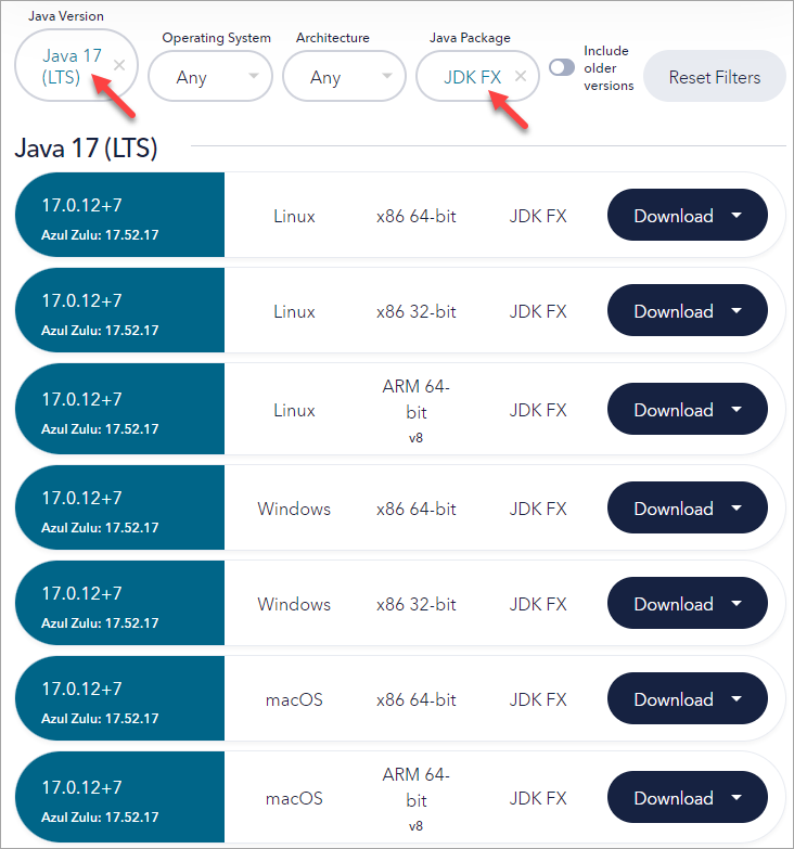
Azul Zulu: 17 JDK FX — https://www.azul.com/downloads/?version=java-17-lts&package=jdk-fx#zulu
It is important that Java Package = JDK FX is selected for download.
-
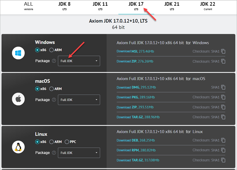
17 JDK FX: https://axiomjdk.ru/pages/downloads/#/java-17-lts
It is important that Java Package = JDK FX is selected for download.
If you have projects on older versions of 1C:EDT that use Java 11, make the settings listed in section About Sharing Java 11 and Java 17.
About Sharing Java 11 and Java 17
Different versions of 1C:EDT may require different versions of Java. For example, 2023.3 requires Liberica 11, and 2024.1 requires Axiom 17. If you want to simultaneously use versions of 1C:EDT that require different versions of Java, we recommend that you do the following:
-
Install Java 17. It will be your default Java
-
Remove the path to Java 11 from the Path system variable. To do this:
-
Type "change system variables" in the search field.
-
Open the System Properties dialog box. On the Advanced tab, click Environment Variables...
-
In the System Variables list, select Path and click Edit...
-
Select the line with the path to Java 11 and click Delete.
-
Click OK three times to close the open dialogs.
-
-
Make sure that for old projects or Development Environments, the path to Java 11 is specified:
-
If you are using the 1C:EDT Start launcher and updater, make sure that the path to Java 11 is configured for old installed Development Environments.
-
If you are not using 1C:EDT Start, make sure that the path to Java 11 is configured in the 1cedt.ini file for older versions of 1C:EDT.
-
Remove the Ring Utility if It Was Installed Previously
If you have already installed 1C:Enterprise software products on your computer, then you may have also installed the ring utility along with them. This utility is part of the platform and allows you to manage the local configuration of 1C:Enterprise system processes (more details).
The installer included in the 1C:EDT installation package, in addition to 1C:EDT itself, will also install the ring utility on your computer. You may need this utility in order to run 1C:EDT from the command line to perform routine operations.
Since the installer does not use the operating system's package managers, the ring utility installed by the old installation program must be removed before performing the first installation of 1C:EDT using the installer.
-
To find out if the ring utility is installed, open the list of installed Windows apps (Start > Settings > Apps).
-
If the utility is installed, you will see it in the list (1C:Enterprise Ring).
-
Remove it (click on it and then Remove).
Install 1C:EDT
Trouble: If this is not your first installation, terminate the launcher and updater (1C:EDT Start).
Launch the installer. To do this:
Windows
-
If you are using a self-extracting installation package, just run the downloaded
.exefile. -
Otherwise:
-
Extract the archive containing 1C:EDT to any directory.
-
Run the
1ce-installer.exefile as administrator (Run as administrator in the context menu).
-
Linux
-
Extract the installation package archive.
-
Open a terminal and go to the directory with the extracted archive.
-
Run:
sudo ./1ce-installerWarning: In Linux, there may be problems displaying the installer icon in the taskbar. This is due to limited support for this feature in JavaFX.
macOS
-
In Finder, double-click the
.dmgfile with the installation package. -
In the window that appears, double-click the
1ce-installerfile (or1ce-installer.app, if you have extensions for all files). -
The administrator rights request will be triggered automatically.
Trouble: If you launched the 1ce-installer.exe file, but the 1C:Enterprise Installer splash screen did not appear, most likely something is wrong with Java on your computer:
-
Make sure Java is installed.
-
Make sure Java supports OpenJFX (JavaFX). For example, if you installed Liberica JDK from the developer portal, then you need a full installation package.
-
Make sure the JAVA_HOME variable is set correctly (How to set up Java).
Another reason for this malfunction may be Cyrillic characters in the path to the directory from which you are running 1ce-installer.exe. In this case, simply rename the folder or move the installation package to another directory.
The installer is cross-platform, it has the same (to the extent it is possible) graphical interface on all of the listed operating systems.
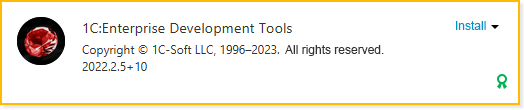
Some time after launch, it will show the name and characteristics of the 1C:EDT version being installed. The Install action will automatically be selected for it.
-
Setting the Home Installation Directory When You First Run the Installer Warning: Only the first time you run the installer you can select the home directory where all versions of 1C:EDT and other 1C:Enterprise apps will be installed. The Installation Home Directory field is located at the bottom of the window.
An individual own home directory used by the installer allows you to always have only one copy of 1C:EDT of a specific version, without duplication.
The next time you run the installer, you will no longer be able to change the home directory in its dialog. But if necessary, you can move the home directory to any disk by putting a link on the file system to the original directory.
Warning: For macOS, it is recommended not to change the installation home directory to one that is not a subdirectory in /Applications. The installer will function correctly with any directory, but macOS in this case will not automatically add installed applications to the Launchpad screen and they will have to be launched manually. If there is a need to change the installation home directory, then a possible workaround is to manually create symbolic links to applications in /Applications.
-
Digital Signature Validation All components of the 1C:EDT installation package are signed with a digital signature. The installer validates this signature and displays the validation result next to the version name.
If a green medal icon
 is displayed, it means the digital signature has been successfully validated, and the installation package can be safely installed.
If a red triangle icon
 is displayed, it means the digital signature validation failed. In this case, you can still install the installation package, but at your own risk.
A digital signature may fail validation for two reasons: either the installation package files have been compromised (meaning they are not the files supplied by 1C Company) or the digital signature validation is incorrectly configured on your computer. Click the red triangle icon to view detailed information about the digital signature validation for each component included in the distribution package.
-
Installation To start the installation, click Install. The indicator will inform you about the progress of the installation.
When the installation is complete, its result will be shown on the screen. You can follow the links from the Next section to read related information, or you can click Finish to exit the installer.
-
Tip: If you want to get acquainted with all the features of the installer, its documentation is published on the ITS portal.
Further Actions
-
First Launch of 1C:EDT Installed from the Main Installation Package
-
Installing Additional Software for Debugging Desktop Applications
Installing 1C:EDT Using the Console Version of the Installer
Prepare the 1C:EDT installation package for use from the command line:
Windows
-
Extract the archive containing 1C:EDT to any directory.
-
Launch the Command Prompt application as an administrator (Run as administrator from the context menu).
-
Navigate to the directory with the extracted archive.
Linux
-
Extract the installation package archive.
-
Open a terminal and go to the directory with the extracted archive.
To install 1C:EDT, run the console version of the Installer (1ce-installer-cli) with the install command, for example:
1ce-installer-cli installThis command will install 1C:EDT from the installation package located in the same directory as 1ce-installer-cli.
You can use additional options and parameters. Options are specified before the command name. Parameters are specified after the command name.
--verbose
Logging level during the installation process. Possible values, from lowest to highest, are info, detailed, and full. The default value is info.
It affects the number and detail of messages about errors or problems. A higher verbosity level means more messages, some of which contain a detailed stack trace.
For example:
1ce-installer-cli --verbose full installThis command will install 1C:EDT from the installation package located in the same directory as 1ce-installer-cli. The maximum logging level will be used.
--source
The path to the directory containing the installation package. The default value is the directory from which 1ce-installer-cli is run.
For example:
1ce-installer-cli install --source C:\dist\dist1This command will install 1C:EDT from the installation package located in the C:\dist\dist1 directory.
Note: To learn about other options for the install command, run the command:
1ce-installer-cli install --helpInstalling Additional Software for Debugging Desktop Applications
1C:EDT lets you create and modify 1C:Enterprise applications, but you will need the 1C:Enterprise Platform, and possibly additional software, to launch and debug them.
The components that you need to install additionally are listed below for each of the 1C:Enterprise Platform deployment options.
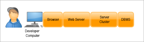
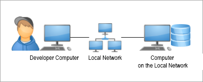
1C:Enterprise Deployment: Thin Client on a Local Network, File Mode
In this scenario, the user typically interacts with the infobase as follows:
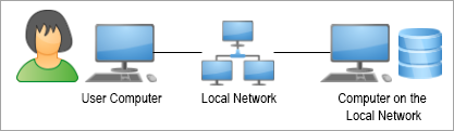
The file infobase is located on a computer on the local network.
The user launches the thin client. On the user's computer, code written in the 1C:Enterprise language is executed in the client and server contexts. The thin client creates a specialized server environment on the user's computer.
Deployment
To simulate this operation on your computer, you need to install the 1C:Enterprise Platform.
You will need the following components:
Windows and Linux
The 1C:Enterprise component (includes Designer, thin client, and file DBMS).
macOS
The installation program does not allow you to control the installation options. You must install everything.
If you are using Windows and have the 1C:Enterprise platform installed on your computer, you can check which platform components are installed in each version. Open Settings > Applications (or Control Panel > Programs > Programs and Features), select the version of the platform you are interested in, click Modify, then in the dialog, when Modify is selected, click Next to see a list of installed platform components. If you do not intend to change anything, press Cancel.
When 1C:EDT starts, it automatically detects and adds all installed platform versions to its settings. If you installed a new platform version while 1C:EDT was running, update the platform versions.
Another Deployment Option
If you're on a local network, you can create the infobase on a network computer.

Warning: In the macOS operating system, this deployment option is not possible because the client app does not support file infobases located on a network resource. See Features of Running a Client Application Under macOS.
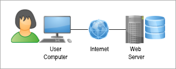
1C:Enterprise Deployment: Thin Client over the Internet, File Mode
In this scenario, the user typically interacts with the infobase as follows:
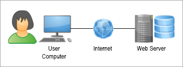
A web server exists on the Internet, where the thin client for the file infobase is published. The infobase file itself is located on the same computer as the web server.
The user launches the thin client. On the user's computer, code written in the 1C:Enterprise language is executed in the client context. On the web server computer, the web server extension module creates a specialized server environment for the published infobase. In this environment, code written in 1C:Enterprise language is executed in the server context.
Deployment
To simulate this operation on your computer, you need to install:
-
A web server (optional: you can use one of the built-in 1C:EDT web servers or install your own).
Installing the 1C:Enterprise Platform
You will need the following components:
Windows and Linux
-
1C:Enterprise (includes Designer and thin client).
-
Web Server Extension Modules.
macOS
The installation program does not allow you to control the installation options. You must install everything.
If you are using Windows and have the 1C:Enterprise platform installed on your computer, you can check which platform components are installed in each version. Open Settings > Applications (or Control Panel > Programs > Programs and Features), select the version of the platform you are interested in, click Modify, then in the dialog, when Modify is selected, click Next to see a list of installed platform components. If you do not intend to change anything, press Cancel.
When 1C:EDT starts, it automatically detects and adds all installed platform versions to its settings. If you installed a new platform version while 1C:EDT was running, update the platform versions.
Installing the Web Server
On Windows and Linux, you can use one of the built-in 1C:EDT web servers for publishing infobases (learn more):
-
Built-in Apache 2.4: a web server included with 1C:EDT,
-
1C:Link: a web server located in the 1C:Link service. 1C:EDT is integrated with the 1C:Link service and allows you to publish your infobases on this service.
If you are using macOS, or if the built-in web servers do not suit you for any reason, you will need to install one of the web servers supported by the 1C:Enterprise Platform (see Supported Web Servers).
1C:EDT also automatically detects and adds all installed web servers.
If you installed a web server while 1C:EDT was running, go to the Web Servers panel and press  (Refresh) in its command toolbar.
If 1C:EDT could not add the web server automatically, you can add it manually.
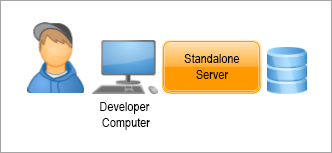
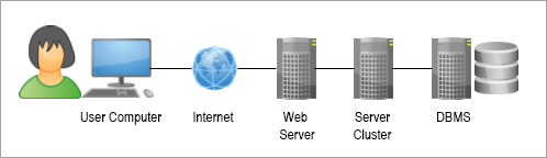
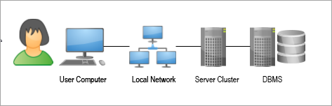
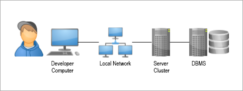
1C:Enterprise Deployment: Thin Client on the Local Network, Client-Server Mode
In this scenario, the user typically interacts with the infobase as follows:
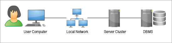
A 1C:Enterprise server cluster is located on one of the computers on the local network. A database management system, which stores the client-server infobase, is located on another computer.
The user launches the thin client. On the user's computer, code written in the 1C:Enterprise language is executed in the client context. Code is executed in the server context on the server cluster computer.
Deployment
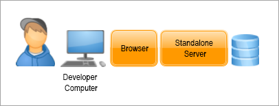
There are two ways to simulate this operation on your computer:
Option 1. Using a standalone server. You need to install the 1C:Enterprise Platform (with the server cluster included) on your computer.

In this case, you will be able to interact with a file infobase.
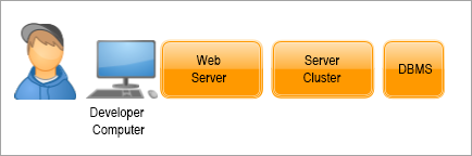
Option 2. Using a server cluster. You need to install the following on your computer:
- the 1C:Enterprise Platform, which includes a server cluster
- a DBMS supported by the platform

In this case, you will be able to interact with a client-server infobase.
Warning: On macOS, you will not be able to use the second option because the cluster only runs on Windows and Linux operating systems. Therefore, you can use either a standalone server or an existing cluster on the local network.
Installing the 1C:Enterprise Platform
You will need the following components:
Windows and Linux
-
1C:Enterprise (includes Designer and thin client).
-
1C:Enterprise Server (includes server cluster and standalone server).
macOS
The installation program does not allow you to control the installation options. You must install everything.
If you are using Windows and have the 1C:Enterprise platform installed on your computer, you can check which platform components are installed in each version. Open Settings > Applications (or Control Panel > Programs > Programs and Features), select the version of the platform you are interested in, click Modify, then in the dialog, when Modify is selected, click Next to see a list of installed platform components. If you do not intend to change anything, press Cancel.
When 1C:EDT starts, it automatically detects and adds all installed platform versions to its settings. If you installed a new platform version while 1C:EDT was running, update the platform versions.
For cluster administration (on any operating system) starting from platform version 8.3.15, you can use the standard Server Management function. It is available in any application in 1C:Enterprise mode. To access it, go to Main Menu > All Functions > Standard > Server Management.
Trouble: If the All Functions command is missing, enable its visibility by selecting Main Menu > Settings > Preferences... and enabling Show Command All Functions.
In platform 8.3.14, this standard function is not available, but you can use a similar universal data processor Server Management. This data processor can be run in any application.
For cluster administration in earlier platform versions, see Cluster Server Administration.
Installing the Database Management System
You will need to install one of the DBMSs supported by the 1C:Enterprise Platform (see Installing Database Servers).
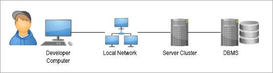
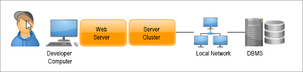
Other Deployment Options
If a suitable DBMS is installed on your local network, you can install only the server cluster on your computer and do not need to install the DBMS. You will create the infobase in the existing DBMS.
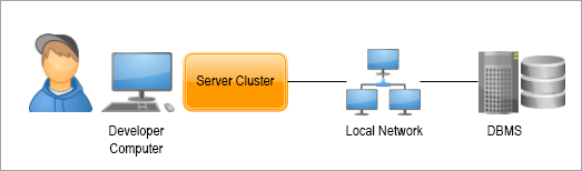
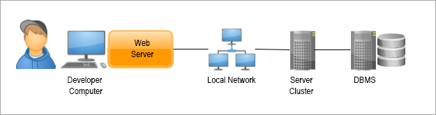
If a 1C:Enterprise server cluster is installed on your local network, you do not need to install a cluster and DBMS on your computer. You will create the infobase in the existing cluster.
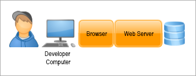
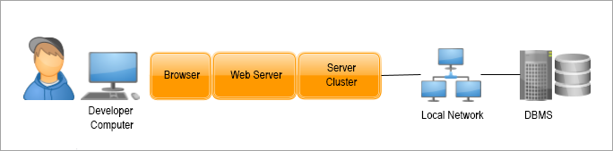
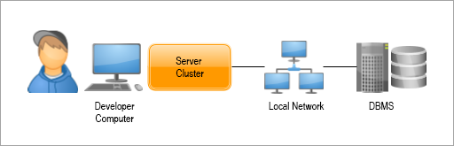
1C:Enterprise Deployment: Thin Client over the Internet, Client-Server Mode
In this scenario, the user typically interacts with the infobase as follows:
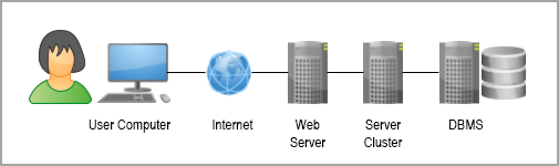
A 1C:Enterprise server cluster is located on one of the computers on the local network. A database management system, which stores the client-server infobase, is located on another computer. This infobase's thin client is published on a web server accessible from the Internet.
The user launches the thin client. On the user's computer, code written in the 1C:Enterprise language is executed in the client context. Code is executed in the server context on the server cluster computer.
Deployment
There are two ways to simulate this operation on your computer:
-
Using a standalone server. You need to install the 1C:Enterprise Platform (with the server cluster included) on your computer.
In this case, you will be able to interact with a file infobase.
-
Using a server cluster. You need to install the following on your computer:
-
The 1C:Enterprise Platform, which includes a server cluster.
-
A DBMS supported by the platform.
-
A web server (optional: you can use one of the built-in 1C:EDT web servers or install your own).
In this case, you will be able to interact with a client-server infobase.
-
Warning: On macOS, you will not be able to use the second option because the cluster only runs on Windows and Linux operating systems. Therefore, you can either use a standalone server or use a cluster that already exists on your local network.
Installing the 1C:Enterprise Platform
You will need the following components:
Windows and Linux
-
1C:Enterprise (includes Designer and thin client).
-
1C:Enterprise Server (includes the server cluster and the standalone server).
-
Web Server Extension Modules.
macOS
The installation program does not allow you to control the installation options. You must install everything.
If you are using Windows and have the 1C:Enterprise platform installed on your computer, you can check which platform components are installed in each version. Open Settings > Applications (or Control Panel > Programs > Programs and Features), select the version of the platform you are interested in, click Modify, then in the dialog, when Modify is selected, click Next to see a list of installed platform components. If you do not intend to change anything, press Cancel.
When 1C:EDT starts, it automatically detects and adds all installed platform versions to its settings. If you installed a new platform version while 1C:EDT was running, update the platform versions.
For cluster administration (on any operating system) starting from platform version 8.3.15, you can use the standard Server Management function. It is available in any application in 1C:Enterprise mode. To access it, go to Main Menu > All Functions > Standard > Server Management.
Trouble: If the All Functions command is missing, enable its visibility by selecting Main Menu > Settings > Preferences... and enabling Show Command All Functions.
In platform 8.3.14, this standard function is not available, but you can use a similar universal data processor Server Management. This data processor can be run in any application.
For cluster administration in earlier platform versions, see Cluster Server Administration.
Installing the Database Management System
You will need to install one of the DBMSs supported by the 1C:Enterprise Platform (see Installing Database Servers).
Installing the Web Server
On Windows and Linux, you can use one of the built-in 1C:EDT web servers for publishing infobases (learn more):
-
Built-in Apache 2.4: a web server included with 1C:EDT,
-
1C:Link: a web server located in the 1C:Link service. 1C:EDT is integrated with the 1C:Link service and allows you to publish your infobases on this service.
If you are using macOS, or if the built-in web servers do not suit you for any reason, you will need to install one of the web servers supported by the 1C:Enterprise Platform (see Supported Web Servers).
1C:EDT also automatically detects and adds all installed web servers.
If you installed a web server while 1C:EDT was running, go to the Web Servers panel and press (Refresh) in its command toolbar.
If 1C:EDT could not add the web server automatically, you can add it manually.
Other Deployment Options
If a suitable DBMS is installed on your local network, you do not need to install a DBMS on your computer. You will create the infobase in the existing DBMS.
If a 1C:Enterprise server cluster is installed on your local network, you do not need to install a cluster and DBMS on your computer. You will create the infobase in the existing cluster.
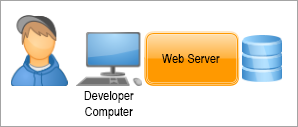
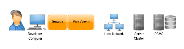
1C:Enterprise Deployment: Web Client, File Mode
In this scenario, the user typically interacts with the infobase as follows:
A web server on the Internet hosts the published web client for the file infobase. The infobase file itself is located on the same computer as the web server.
The user starts a browser and enters the address of the web server where the web client for the infobase is published. The web client is downloaded to the user's computer and starts running in the browser environment. On the user's computer, code written in the 1C:Enterprise language is executed in the client context. On the web server computer, the web server extension module creates a specialized server environment for the published infobase. In this environment, code written in 1C:Enterprise language is executed in the server context.
Deployment
To simulate this operation on your computer, you need to install:
-
A web server (optional: you can use one of the built-in 1C:EDT web servers or install your own).
-
A browser.
Installing the 1C:Enterprise Platform
You will need the following components:
Windows and Linux
-
1C:Enterprise (includes Designer and thin client).
-
Web Server Extension Modules.
macOS
The installation program does not allow you to control the installation options. You must install everything.
If you are using Windows and have the 1C:Enterprise platform installed on your computer, you can check which platform components are installed in each version. Open Settings > Applications (or Control Panel > Programs > Programs and Features), select the version of the platform you are interested in, click Modify, then in the dialog, when Modify is selected, click Next to see a list of installed platform components. If you do not intend to change anything, press Cancel.
When 1C:EDT starts, it automatically detects and adds all installed platform versions to its settings. If you installed a new platform version while 1C:EDT was running, update the platform versions.
Installing the Web Server
On Windows and Linux, you can use one of the built-in 1C:EDT web servers for publishing infobases (learn more):
-
Built-in Apache 2.4: a web server included with 1C:EDT,
-
1C:Link: a web server located in the 1C:Link service. 1C:EDT is integrated with the 1C:Link service and allows you to publish your infobases on this service.
If you are using macOS, or if the built-in web servers do not suit you for any reason, you will need to install one of the web servers supported by the 1C:Enterprise Platform (see Supported Web Servers).
1C:EDT also automatically detects and adds all installed web servers.
If you installed a web server while 1C:EDT was running, go to the Web Servers panel and press (Refresh) in its command toolbar.
If 1C:EDT could not add the web server automatically, you can add it manually.
Installing the Browser
You will need to install a browser supported by the 1C:Enterprise Platform (see Hardware Requirements. Web Client).
You also need to configure certain browser settings (see Configuring Web Browsers for Use in the Web Client).
1C:Enterprise Deployment: Web Client, Client-Server Mode
In this scenario, the user typically interacts with the infobase as follows:
A 1C:Enterprise server cluster is located on one of the computers on the local network. A database management system, which stores the client-server infobase, is located on another computer. The web client for this infobase is published on a web server accessible from the Internet.
The user starts a browser and enters the address of the web server where the web client for the infobase is published. The web client is downloaded to the user's computer and starts running in the browser environment. On the user's computer, code written in the 1C:Enterprise language is executed in the client context. Code is executed in the server context on the server cluster computer.
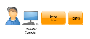
Deployment on the Developer's Computer
There are two ways to simulate this operation on your computer:
-
Using a standalone server. You need to install the following on your computer:
-
The 1C:Enterprise Platform, which includes a server cluster.
-
A browser.
In this case, you will be able to interact with a file infobase.
-
-
Using a server cluster. You need to install the following on your computer:
-
The 1C:Enterprise Platform, which includes a server cluster.
-
A DBMS supported by the platform.
-
A web server (optional: you can use one of the built-in 1C:EDT web servers or install your own).
-
A browser.
In this case, you will be able to interact with a client-server infobase.
-
Warning: On macOS, you will not be able to use the second option because the cluster only runs on Windows and Linux operating systems. Therefore, you can either use a standalone server or use a cluster that already exists on your local network.
Installing the 1C:Enterprise Platform
You will need the following components:
Windows and Linux
-
1C:Enterprise (includes Designer and thin client).
-
1C:Enterprise Server.
-
Web Server Extension Modules.
macOS
The installation program does not allow you to control the installation options. You must install everything.
If you are using Windows and have the 1C:Enterprise platform installed on your computer, you can check which platform components are installed in each version. Open Settings > Applications (or Control Panel > Programs > Programs and Features), select the version of the platform you are interested in, click Modify, then in the dialog, when Modify is selected, click Next to see a list of installed platform components. If you do not intend to change anything, press Cancel.
When 1C:EDT starts, it automatically detects and adds all installed platform versions to its settings. If you installed a new platform version while 1C:EDT was running, update the platform versions.
For cluster administration (on any operating system) starting from platform version 8.3.15, you can use the standard Server Management function. It is available in any application in 1C:Enterprise mode. To access it, go to Main Menu > All Functions > Standard > Server Management.
Trouble: If the All Functions command is missing, enable its visibility by selecting Main Menu > Settings > Preferences... and enabling Show Command All Functions.
In platform 8.3.14, this standard function is not available, but you can use a similar universal data processor Server Management. This data processor can be run in any application.
For cluster administration in earlier platform versions, see Cluster Server Administration.
Installing the Database Management System
You will need to install one of the DBMSs supported by the 1C:Enterprise Platform (see Installing Database Servers).
Installing the Web Server
On Windows and Linux, you can use one of the built-in 1C:EDT web servers for publishing infobases (learn more):
-
Built-in Apache 2.4: a web server included with 1C:EDT,
-
1C:Link: a web server located in the 1C:Link service. 1C:EDT is integrated with the 1C:Link service and allows you to publish your infobases on this service.
If you are using macOS, or if the built-in web servers do not suit you for any reason, you will need to install one of the web servers supported by the 1C:Enterprise Platform (see Supported Web Servers).
1C:EDT also automatically detects and adds all installed web servers.
If you installed a web server while 1C:EDT was running, go to the Web Servers panel and press (Refresh) in its command toolbar.
If 1C:EDT could not add the web server automatically, you can add it manually.
Installing the Browser
You will need to install a browser supported by the 1C:Enterprise Platform (see Hardware Requirements. Web Client).
You also need to configure certain browser settings (see Configuring Web Browsers for Use in the Web Client).
Other Deployment Options
If a suitable DBMS is installed on your local network, you do not need to install a DBMS on your computer. You will create the infobase in the existing DBMS.
If a 1C:Enterprise server cluster is installed on your local network, you do not need to install a cluster and DBMS on your computer. You will create the infobase in the existing cluster.
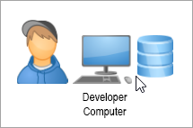
1C:Enterprise Deployment: Thick Client, File Mode
In this scenario, the user typically interacts with the infobase as follows:
The file infobase is located on a computer on the local network.
The user launches the thick client. On the user's computer, code written in the 1C:Enterprise language is executed in the client and server contexts. The thick client itself implements all the functionality of the file DBMS.
Deployment
To simulate this operation on your computer, you need to install the 1C:Enterprise Platform.

Note: There is another deployment option.
Installing the 1C:Enterprise Platform
You will need the following components:
Windows and Linux
The 1C:Enterprise component (includes Designer, thick client, and file DBMS).
macOS
The installation program does not allow you to control the installation options. You must install everything.
If you are using Windows and have the 1C:Enterprise platform installed on your computer, you can check which platform components are installed in each version. Open Settings > Applications (or Control Panel > Programs > Programs and Features), select the version of the platform you are interested in, click Modify, then in the dialog, when Modify is selected, click Next to see a list of installed platform components. If you do not intend to change anything, press Cancel.
When 1C:EDT starts, it automatically detects and adds all installed platform versions to its settings. If you installed a new platform version while 1C:EDT was running, update the platform versions.
Another Deployment Option
If you're on a local network, you can create the infobase on a network computer.
Warning: In the macOS operating system, this deployment option is not possible because the client app does not support file infobases located on a network resource. See Features of Running a Client Application Under macOS.
1C:Enterprise Deployment: Thick Client, Client-Server Mode
In this scenario, the user typically interacts with the infobase as follows:
A 1C:Enterprise server cluster is located on one of the computers on the local network. A database management system, which stores the client-server infobase, is located on another computer.
The user launches the thick client. On the user's computer, code written in the 1C:Enterprise language is executed in the client context. Code is executed in the server context on the server cluster computer.
Deployment
To simulate this operation on your computer, you need to install:
-
The 1C:Enterprise Platform, which includes a server cluster.
-
A DBMS supported by the platform.
Warning: On macOS, the only option is to use an existing cluster on the local network because the cluster only runs on Windows and Linux.
Installing the 1C:Enterprise Platform
You will need the following components:
Windows and Linux
-
1C:Enterprise (includes Designer and the thick client).
-
1C:Enterprise Server.
macOS
The installation program does not allow you to control the installation options. You must install everything.
If you are using Windows and have the 1C:Enterprise platform installed on your computer, you can check which platform components are installed in each version. Open Settings > Applications (or Control Panel > Programs > Programs and Features), select the version of the platform you are interested in, click Modify, then in the dialog, when Modify is selected, click Next to see a list of installed platform components. If you do not intend to change anything, press Cancel.
When 1C:EDT starts, it automatically detects and adds all installed platform versions to its settings. If you installed a new platform version while 1C:EDT was running, update the platform versions.
For cluster administration (on any operating system) starting from platform version 8.3.15, you can use the standard Server Management function. It is available in any application in 1C:Enterprise mode. To access it, go to Main Menu > All Functions > Standard > Server Management.
Trouble: If the All Functions command is missing, enable its visibility by selecting Main Menu > Settings > Preferences... and enabling Show Command All Functions.
In platform 8.3.14, this standard function is not available, but you can use a similar universal data processor Server Management. This data processor can be run in any application.
For cluster administration in earlier platform versions, see Cluster Server Administration.
Installing the Database Management System
You will need to install one of the DBMSs supported by the 1C:Enterprise Platform (see Installing Database Servers).
Other Deployment Options
If a suitable DBMS is installed on your local network, you can install only the server cluster on your computer and do not need to install the DBMS. You will create the infobase in the existing DBMS.
If a 1C:Enterprise server cluster is installed on your local network, you do not need to install a cluster and DBMS on your computer. You will create the infobase in the existing cluster.
First Launch of 1C:EDT Installed from the Main Installation Package
The main way to interact with 1C:EDT is to use the 1C:EDT Start program. It allows you to manage all your projects and versions of 1C:EDT installed on your computer. At the same time, you can run specific versions of 1C:EDT "manually", without using the launch and update program, if necessary.
Create a New Project
1C:EDT Start can be launched in several ways:
-
Using the shortcut 1CEDT Start on the desktop (Windows and Linux).
Note: A large number of incompatible shells (desktop environments) have been created for Linux. This affects the process of creating shortcuts for installed software. The installer follows the Desktop Menu Specification by FreeDesktop. More information is available here. It has been tested on Gnome 3 and KDE 5.
-
Using the command Start > 1C Enterprise Development Tools > 1CEDT Start (Windows) or through the 1CEDT Start command in Launchpad (macOS).
-
By running the executable file 1cedtstart from the home installation directory.
With a standard installation, this file is located in the following directories (your 1C:EDT Start version may differ from the one listed here):
Windows
%ProgramFiles%\1C\1CE\components\1c-edt-start-0.6.0+244-x86_64\1cedtstart.exeLinux
/opt/1C/1CE/components/1c-edt-start-0.6.0+244-x86_64/1cedtstartmacOS
/Applications/1C/1CE/components/1c-edt-start-0.6.0+244-x86_64/1cedtstart (0.6.0+244).appAfter the first launch, 1C:EDT Start opens a welcome window.
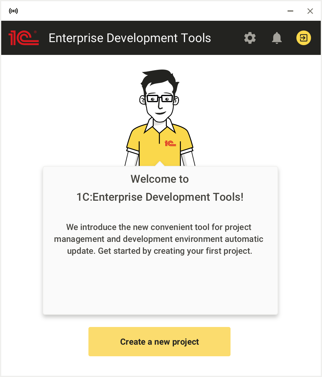
-
Click Create a new project.
1C:EDT Start will prompt you to sign in. Authorization on the 1C:ITS portal is required so that you can automatically install Development Environments and receive updates for them.
-
Click Sign in with 1C:ITS Portal.
1C:EDT Start will open a new browser tab for you to sign in to the portal. If you do not have an account on the portal, click No username? and create an account.
-
After authorization is complete, the browser will notify you. You can close it.
-
Return to 1C:EDT Start.
-
Click New Project.
-
Select the project type 1C:Enterprise Application. To do this, hover over the project type and click the down arrow
 .
.In a project of this type, you can develop one application solution plus several extensions and processing for it. By clicking the down arrow you select the latest version of the Development Environment.
-
Enter the project name and click OK.
-
If needed, change the default location for your project (1C:EDT Workspace) suggested by 1C:EDT Start.
-
Click Add Project.
1C:EDT Start will create a workspace and start downloading and installing the Development Environment. A progress indicator shows you the status of the process.
-
During the download process, 1C:EDT Start will ask you to accept license agreements. Click Accept All. In the future, they will be accepted automatically.
If desired, uncheck Remember Accepted Licenses to accept or decline each license individually.
-
After completing all operations, the new project will appear in the list in a stopped state.
Configure the Development Environment
After you have installed a new Development Environment, configure it. These settings will be used for all projects that use this Development Environment.
If any of the projects require special settings, you can set them in the project itself.
1. Open Development Environment settings
To open the Development Environment settings, do the following:
- Click the gear icon
 in the 1C:EDT Start header.
 - Click the line in the Development Environments section.
- Hover over the desired installed Development Environment and click the gear icon
 .
.
Settings are saved during editing. To exit the settings, click the arrow  or the cross
  in the header.
2. Specify the path to the Java Virtual Machine
In the Java VM field, specify the path to the Java Virtual Machine. If you installed the Liberica JDK installation package in the standard way, specify the following paths:
Windows
C:\Program Files\BellSoft\LibericaJDK-11-Full\binLinux
/usr/lib/jvm/bellsoft-java11.x86_64/binmacOS
/Library/Java/JavaVirtualMachines/liberica-jdk-11.0.4/Contents/Home/bin3. Increase the maximum allocated memory
Importing large standard configurations like 1C:ERP can take a long time and require a significant amount of RAM. Therefore, if you plan to perform such an import, increase the amount of memory available to the Java Virtual Machine.
In the Maximum Allocated Memory field, select 8 GB.
4. Change the location of the temporary directory
Large standard configurations can contain objects with long names.
To load into 1C:EDT, the configuration is first unloaded from the infobase to a temporary directory in a folder hierarchy. This hierarchy repeats the structure of the configuration. As a result, the full path to some .xml configuration file may exceed the limits imposed by the operating system, and the configuration import will end with an error.
To avoid this, place the temporary directory that 1C:EDT uses for importing and exporting configuration files as close to the root of the disk as possible.
Do the following:
- Click Edit as Java VM parameters....
- In the Java VM arguments field, add the line:
-Djava.io.tmpdir=C:\tmpReplace C:\tmp with the temporary file directory you want to use.
5. Set the interface language
1C:EDT uses the operating system's language settings for its interface.
If you are using an English-language operating system and want to interact with 1C:EDT using Russian, in the Interface Language field, select Russian.
Configure Antivirus
Windows Defender or antivirus installed on your computer can reduce the performance and stability of 1C:EDT. Therefore, we recommend adding the following to the exceptions (exclude from scanning):
1. Exclude the application 1cedt.exe.
With a standard installation from 1C:EDT Start, this file is located in the following directories (your 1C:EDT version may differ from the one listed here):
Windows: %USERPROFILE%\AppData\Local\1C\1cedtstart\installations\1C_EDT 2022.2_\1cedt\1cedt.exe
Linux: ~/.local/share/1C/1cedtstart/installations/1C_EDT 2022.2/1cedt/1cedt
macOS: ~/Library/Application Support/1C/1cedtstart/installations/1C_EDT 2022.2/1cedt.app
2. Exclude directories of workspaces used by 1C:EDT.
3. Exclude directories where local Git repositories are located.
Configure Team Development
If you are going to develop a project together with other developers, configure the Git settings (see Setting Up Team Development).
Configure Mobile Application Development
If you are going to develop mobile applications, add a mobile version of the platform, install additional software and configure debugging of mobile applications (see Installing the Platform and Selecting the Development Method).
Updating with 1C:EDT Start
1C:EDT Start distinguishes 1C:EDT versions down to the release level (i.e., the second digit of the version).
For example, versions 2022.1.3 and 2022.1.5 are the same release: 2022.1. Therefore, you cannot have both of these versions installed simultaneously on your computer using 1C:EDT Start. If you have 2022.1.3 installed and you want to install 2022.1.5, the previous version will be updated to the new one. Accordingly, all projects that used version 2022.1.3 will now run on version 2022.1.5. This operation is called updating a release.
With 1C:EDT Start, you can install two different releases on the same computer, for example, 2022.1 and 2022.2. If you have version 2022.1.3 installed and you want to install version 2022.2.5, the previous version will not be affected. Thus, some projects can use version 2022.1.3, and other projects can use version 2022.2.5. This operation is called installing a new release.
Note: When using the offline installation package, each version is installed separately, so you can simultaneously use versions 2022.1.3 and 2022.1.5, for example.
Updating a Release
1C:EDT Start notifies you about new releases. If a new version of an installed release is available, you can automatically update it in several ways.
-
- Open the notifications.
- In the notification about the release of the required version, click Install.
-
Updating from a Development Environment
- Open the development environments.
- Hover over the version with the What's New... note and click the curved arrow
 .
.
The installed release will be updated, and all projects using it will run on the new version of this release.
Switching a Project to a New Release
-
Open the project settings.
-
Scroll down to the Development Environment section.
-
Click the pencil icon
 next to the selected development environment.
 -
Choose an installed or available release of the development environment.
-
Close the project settings.
If you select a non-installed development environment, it will be downloaded and installed when the project is launched.
Removing 1C:EDT, 1C:EDT Start, and the Installer
To remove 1C:EDT from your computer, follow these steps:
1. Terminate 1C:EDT Start.
2. Delete the user data directory. With a standard installation, this directory is located in:
Windows
%USERPROFILE%\AppData\Local\1C\1cedtstartLinux
~/.local/share/1C/1cedtstartmacOS
~/Library/Application Support/1C/1cedtstart3. Delete all 1C:EDT products.
3.1. Launch the installer (your installer version may differ from the one specified here). With a standard installation, the executable file is located in:
Windows
%ProgramFiles%\1C\1CE\components\1c-enterprise-installer-1.12.7+10-x86_64\1ce-installer.exeLinux
/opt/1C/1CE/components/1c-enterprise-installer-1.12.7+10-x86_64/1ce-installermacOS
/Applications/1C/1CE/components/1c-enterprise-installer-1.12.7+10-x86_64/1ce-installer.app3.2. For all 1C:Enterprise Development Tools products, select the Remove action.
3.3. Click Remove.
4. Delete the installer files. With a standard installation, these files are located in:
Home directory of software products
Windows x86
%ProgramFiles%\1C\1CEWindows x86_64
%ProgramW6432%\1C\1CELinux
/opt/1C/1CEmacOS
/Applications/1C/1CESoftware product registry: the inventory directory and the inventory.loc and inventory.write.lock files
Windows
%ProgramData%\1C\1CELinux
/etc/1C/1CEmacOS
/Library/Application Support/1C/1CELog files
Windows: all directories matching the pattern:
%TEMP%\1ce-installer*Linux: all directories matching the pattern:
/tmp/1ce-installer*Using the Offline Installation Package
The offline installation package implies that you will use 1C:EDT directly, without using the 1C:EDT Start launcher and updater. These launch and update scenarios are described in this section.
However, the offline installation package includes 1C:EDT Start, and you can use it to manage your projects. In this case, see here for the first launch scenario and see here for project management.
Launching 1C:EDT Installed Without the Internet
Tip: The offline installation package implies that you will use 1C:EDT directly, without using the 1C:EDT Start launcher and updater. This is the scenario described in this section. For the first launch using 1C:EDT Start, see here.
You can launch 1C:EDT in several ways (your 1C:EDT version may differ from the version specified here):
Option 1. Use the 1CEDT (2022.2.5+10) shortcut on the desktop (Windows and Linux).
Note: A large number of incompatible shells (desktop environments) have been created for Linux. This affects the process of creating shortcuts for installed software. The installer follows the Desktop Menu Specification by FreeDesktop. More information is available here. It has been tested on Gnome 3 and KDE 5.
Option 2. Use Start > 1C Enterprise Development Tools > 1CEDT (2022.2.5+10) on Windows, or use 1CEDT (2022.2.5+10) in Launchpad on macOS.
Option 3. Run the executable file 1cedt from the installation home directory.
With a standard installation from the full installation package, this file is located in the following directories (your 1C:EDT version may differ from the one listed here):
Windows
%ProgramFiles%\1C\1CE\components\1c-edt-2022.2.5+10-x86_64\1cedt.exeLinux
/opt/1C/1CE/components/1c-edt-2022.2.5+10-x86_64/1cedtmacOS
/Applications/1C/1CE/components/1c-edt-2022.2.5+10-x86_64/1cedt (2022.2.5+10).appWorkspace
Before launching, 1C:EDT will ask you where the workspace will be located.
A workspace is a folder where everything you develop in 1C:EDT is stored. Additionally, some 1C:EDT settings that you may modify during application development are stored in the workspace.
You can have multiple workspaces. It is recommended to use a single workspace for developing one 1C:Enterprise application with multiple extensions, reports, and data processors.
After selecting the workspace, click Launch.
Welcome Page
The Welcome Page is the starting point for getting acquainted with 1C:EDT. It contains links to descriptions of the main features.
At the bottom of the page, there are links to documentation, simple examples to help you get acquainted with 1C:EDT, and links to help you create new projects.
To get started, click Get Started.
Configure 1C:EDT
When installing without the Internet, 1C:EDT settings must be made in the 1cedt.ini file.
With a standard installation, this file is located in the following directories (your 1C:EDT version may differ from the one listed here):
Windows
%ProgramFiles%\1C\1CE\components\1c-edt-2022.2.5+10-x86_64\1cedt.iniLinux
/opt/1C/1CE/components/1c-edt-2022.2.5+10-x86_64/1cedt.inimacOS
/Applications/1C/1CE/components/1c-edt-2022.2.5+10-x86_64/1cedt (2022.2.5+10).app/Contents/Eclipse/1cedt.iniFollow these steps:
-
Close 1C:EDT.
-
Run a text editor as administrator and open the 1cedt.ini file in it.
-
Make changes to it.
-
Save and close the 1cedt.ini file.
-
Launch 1C:EDT.
1. Java Virtual Machine Path
Insert the path to the Java executable before the line -vmargs. If you installed the Liberica JDK installation package in the standard way, then you need to specify the following paths:
Windows
-vm
C:\Program Files\BellSoft\LibericaJDK-11-Full\bin\javaw.exe
Linux
-vm
/usr/lib/jvm/bellsoft-java11.x86_64/bin
macOS
-vm
/Library/Java/JavaVirtualMachines/liberica-jdk-11.0.4/Contents/Home/bin
2. Maximum Allocated Memory
Importing large standard configurations like 1C:ERP can take a long time and require a significant amount of RAM. Therefore, if you plan to perform such an import, increase the amount of memory available to the Java virtual machine.
The default value specified in the file is 4 GB:
-Xmx4096mIncrease it to 8 GB:
-Xmx8g3. Temporary Directory Location
Large standard configurations can contain objects with long names.
To load into 1C:EDT, the configuration is first unloaded from the infobase to a temporary directory in a folder hierarchy. This hierarchy repeats the structure of the configuration. As a result, the full path to some .xml configuration file may exceed the limits imposed by the operating system, and the configuration import will end with an error.
To avoid this, place the temporary directory that 1C:EDT uses for importing and exporting configuration files as close to the root of the disk as possible.
To do this, in the line following the -Xmx parameter, write, for example:
-Djava.io.tmpdir=C:\tmpReplace C:\tmp with the temporary file directory you want to use.
4. Interface Language
1C:EDT uses the operating system's language settings for its interface.
If you are using an English-language operating system and want to interact with 1C:EDT using Russian, add -nl ru after the line com._1c.g5.v8.dt.product.application:
...
-showsplash
com._1c.g5.v8.dt.product.application
-nl ru
...
Configure Antivirus
Windows Defender or antivirus installed on your computer can reduce the performance and stability of 1C:EDT. Therefore, we recommend adding the following to the exceptions (exclude from scanning):
1. Exclude the application 1cedt.exe.
With a standard installation from the full installation package, this file is located in the following directories (your 1C:EDT version may differ from the one listed here):
Windows: %ProgramFiles%\1C\1CE\components\1c-edt-2022.2.5+10-x86_64\1cedt.exe
Linux: /opt/1C/1CE/components/1c-edt-2022.2.5+10-x86_64/1cedt
macOS: /Applications/1C/1CE/components/1c-edt-2022.2.5+10-x86_64/1cedt (2022.2.5+10).app
2. Exclude directories of workspaces used by 1C:EDT.
3. Exclude directories where local Git repositories are located.
Configure Team Development and Mobile Application Development
Configure team development and mobile application development in the same way as for 1C:EDT installed from the main installation package. Skip the "Launch the 1C:EDT Start Project" step, since 1C:EDT is already running.
Updating 1C:EDT Installed Without the Internet
-
Terminate the previous version of 1C:EDT.
-
If you are using 1C:EDT Start, terminate it.
-
Install 1C:EDT from the offline installation package.
-
Launch the new version of 1C:EDT.
-
Select the previous workspace. If necessary, 1C:EDT will convert the data.
Usage Examples
Creating an Infobase from a Template and Adding it to the List of Infobases
One way to create an infobase is to create it using a ready-made configuration template. As a result, the infobase will already contain an application, and possibly even data. This depends on the template used.
In this example, the 1C:Enterprise Platform version 8.3.22.1923 and the Managed Application configuration template version 1.0.36.2, pre-installed on the computer, are used to create the infobase.
You can use a different platform version and a different configuration template from those available on your computer. If you do not have any configuration templates installed, use the distribution package of any 1C:Enterprise application. They all contain one or more templates for the configurations they include.
Important: This example assumes that you have already run 1C:EDT for the first time and configured the development environment.
-
Launch the 1C:EDT Start project.
1C:EDT opens the Welcome panel.
-
Click Get Started.
1C:EDT opens the 1C:Enterprise perspective.
-
Click
 (Infobases) in the collapsed panel on the right.
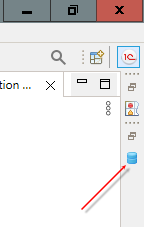
1C:EDT expands the Infobases panel.
-
Click
 (Add...) to create a new infobase.
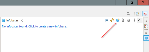
1C:EDT launches the Add Infobase or Group wizard.
-
Click Next.
You do not need to change the settings on this page. By default, 1C:EDT offers to create a new infobase, which is exactly what is required in this example.
-
By default, 1C:EDT offers to create an infobase from a template, which is exactly what is required in this example. Select the configuration template from which the infobase will be created. To do this:
-
Expand the Managed Application Demo Configurations branch.
-
Expand the Demo Configuration "Managed Application" branch.
-
Select version 1.0.36.2.
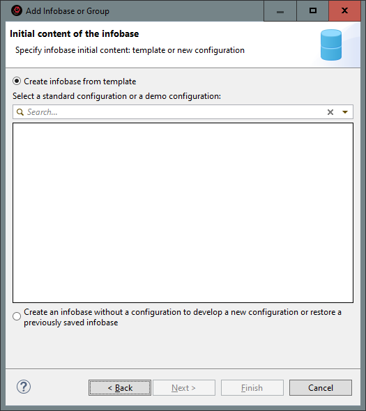
- Click Next.
-
-
Set the infobase name, for example, Demo EDT.
By default, 1C:EDT suggests placing the new infobase on this computer or on a computer on the local network, which is exactly what is required in this example.
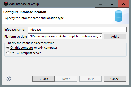
-
Click Next.
-
Click Next.
1C:EDT suggests a default infobase directory. Do not change this directory, as it ensures the correct functioning of the development environment.
-
Click Done.
Do not change the default settings. The infobase will be created and will appear in the Infobases panel.
Importing an Infobase into a New Project
If you have an application that you created or modified using 1C:Enterprise Designer, you can continue developing it in 1C:EDT. This example shows how to import a configuration from a infobase into a new project.
Important: This example assumes that you have already run 1C:EDT for the first time and configured the development environment.
Trouble: Before running the example, make sure that the version of the 1C:Enterprise platform required for the imported infobase is installed on your computer.
-
Launch the 1C:EDT Start project.
-
Click
(Infobases) in the collapsed panel on the right.1C:EDT expands the Infobases panel.
-
Next, you will need to specify the user of the imported infobase under whose account 1C:EDT will interact with that infobase.
If you do not remember which users are in the infobase, launch 1C:Enterprise Designer. To do this, click Launch Designer in the infobase context menu.
-
Drag the selected infobase to the Navigator panel.
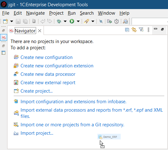
1C:EDT launches the Import Configuration wizard and then opens the Configure access to the infobase window.
-
In the Configure access to the infobase window, specify the access settings that 1C:EDT will use when interacting with this infobase:
-
Access type: Infobase.
-
Username: the name of a user with administrative privileges.
-
Password: the user's password (if any). Click OK.
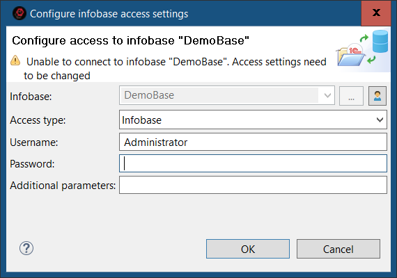
-
-
1C:EDT analyzes the infobase and shows the configuration extensions that can be loaded.
By default, 1C:EDT will offer to use the latest version of the 1C:Enterprise Platform installed on your computer for the new project. If you need a different version for your infobase, select it.
-
Click Import.
1C:EDT starts importing the configuration and extensions.
As a result, a new project containing the imported configuration will be opened in the Navigator panel. Extension projects (an individual project for each extension) will be opened next to it. Their names will contain the name of the parent project as a prefix.
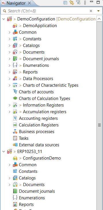
Editing the Configuration
This example demonstrates how to create a new configuration project, create configuration objects, and add event handlers.
Important: This example assumes that you have already run 1C:EDT for the first time and configured the development environment.
Trouble: Before running the example, make sure that the required version of the 1C:Enterprise Platform is installed on your computer.
The example consists of several parts:
Creating a Configuration Project
You will create an empty project to develop a new configuration.
-
Start creating a new configuration.
If you do not have any projects in the Navigator panel, click Create New Configuration in it.
If you have projects in the Navigator panel, click New > Configuration Project... in the context menu in the free area of the Navigator panel.
-
Set the name of the configuration, for example, TestEDT.
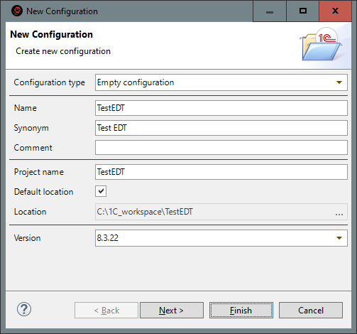
-
Click Done.
As a result, 1C:EDT will do the following:
-
The Navigator panel will show the configuration project containing the empty configuration.
-
The Configuration Properties editor will open in the editor area on the General tab.
-
The Properties panel will also show the configuration properties.
This happened because the branch representing the configuration  was selected in the configuration tree. This behavior of the Properties panel is defined for all branches of the configuration tree that have properties.
If the branch does not have properties (for example, Catalogs or Documents), then when it is selected, the Properties panel will show the properties of the nearest parent (for the mentioned branches, these will be the configuration properties).
Creating a Configuration Object
You will create a catalog named Products.
-
In the Navigator panel, click New > Catalog in the context menu of the Catalogs branch.
-
Enter the name of the catalog: Products.
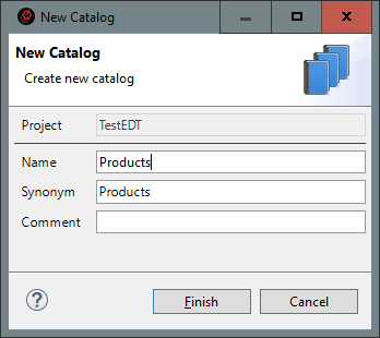
-
Click Done.
As a result, 1C:EDT will do the following:
-
The Navigator panel will show the Products catalog in the Catalogs branch.
-
The Configuration Object editor (with the properties of the Products catalog) will open in the editor area on the General tab.
-
The Properties panel will show the properties of the Products catalog.
Creating a Configuration Object Attribute
You will create an attribute named SKU for the Products catalog.
-
Click Create > Attribute in the context menu of the Products catalog.
-
Enter the name of the attribute: SKU.
By default, 1C:EDT will set its type to String of variable length of 10 characters. This means that if the length of the string placed in this attribute is less than 10 characters, then it will have its own length, and if it is more than 10 characters, then it will be truncated to 10 characters.
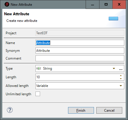
-
Click Done.
As a result, 1C:EDT will do the following:
-
The Navigator panel will show the SKU attribute in the Attributes branch of the Products catalog.
-
The Catalog editor will switch to the Data tab, where the catalog attributes are edited.
-
The Properties panel will show the properties of the SKU attribute.
Creating a Configuration Object Form
In this part of the example, you will create a list form with the default name for the Products catalog.
-
Click New > Form in the context menu on the Forms branch of the Products catalog.
-
Select the form type: Catalog List Form
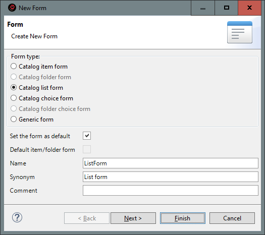
-
Click Done.
As a result, 1C:EDT will do the following:
-
The Navigator panel will show the ListForm form in the Forms branch of the Products catalog.
-
The Properties panel will show the properties of the ListForm form.
-
The form editor will open in the editor area.
Adding a Form Item
In this part of the example, you will add one of the possible elements to the form a decoration and place it at the top of the form.
-
Click Add > Decoration - Label > OK in the context menu on the root of the form tree (Form) in the form editor.
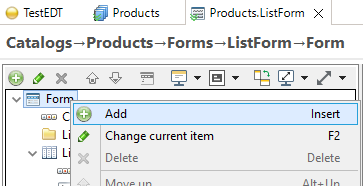
-
Set the title of the decoration: Custom label
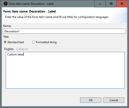
-
Click OK.
The Decoration1 element will appear at the end of the form tree.
-
Move the decoration to the beginning of the tree. To do this, click
 (Move Down) in the form items command bar.
As a result, the Decoration1 element will appear at the beginning of the form tree.
In addition, it will appear in the visible part of the preview window immediately after the command bar.
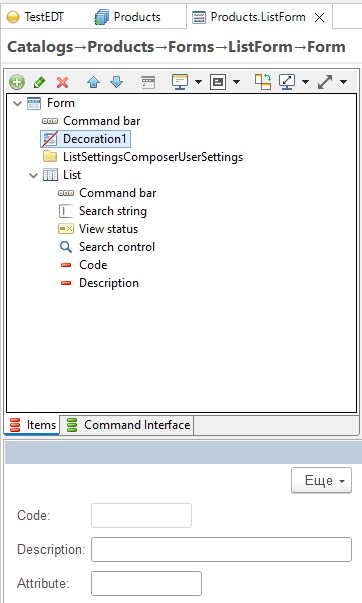
Adding a Form Event Handler
In this part of the example, you will add the OnCreateAtServer() form event handler. In this handler, you usually perform all actions to prepare the form for opening (except for those that can only be run on the client).
-
Open the form module. To do this, go to the Module tab, which is located at the bottom of the editor.
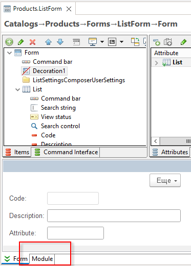
-
Click Add Event Handler in the context menu.
-
To quickly find the desired event, type "add" in the search field.
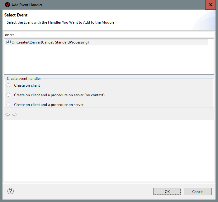
-
Double-click to select the OnCreateAtServer() event.
A declaration of the event handler procedure will appear in the form module.
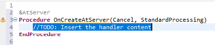
-
Save the changes made to the module. To do this, click
 (Save) in the main window command bar.
As a result, 1C:EDT will save the changes to disk. This is evidenced by the absence of an asterisk in its title.
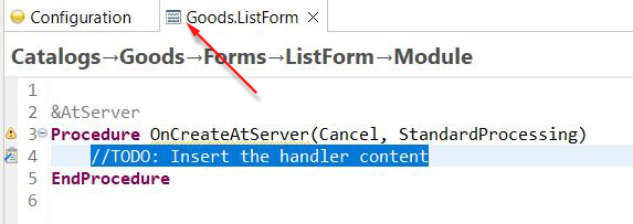
Extending with Plug-ins
Since 1C:EDT is built using Eclipse technologies, you can install additional plug-ins. With plug-ins, you can easily extend the development environment with new features.
For example, if you need more database connectivity options, you can install a plug-in that lets you quickly connect to various DBMSs, view their data structure, and run queries.
You can also create your own plug-ins to extend the existing capabilities of 1C:EDT.
Bundled Plug-ins
The standard 1C:EDT distribution includes several open-source plug-ins. These plug-ins are developed by the community and available on GitHub.com. The plugins are maintained by the community and are distributed under an open-source license. We sincerely thank all community members for their input on the project.
-
1C:SSL support helps to develop configurations more comfortably.
-
1C:Code style V8 helps you develop configurations in accordance with the standards and guidelines of 1C for the 1C:Enterprise platform.
-
1C:EDT Project checks checks the structural integrity of the project, configurations, metadata, etc.
Developing Your Own Plug-ins
Several resources are available to support developers of 1C:EDT plug-ins.
-
1C:EDT Plugin-dev (official) Telegram group. Dedicated to Java development of plug-ins and extension tools for 1C:EDT and the Eclipse RCP ecosystem.
-
Plugin Developer Guide The 1C:EDT Plugin Developer Guide documentation describes configuration metadata models, extension points, and services you may need when developing 1C:EDT plug-ins. It also includes a demo plug-in example, which you can use for learning or as a template for creating your own plug-ins.
-
JavaDoc Description (JavaDoc) of 1C:EDT classes. To include them in 1C:EDT, add com.e1c.g5.v8.dt.javadocs to the target platform.
To see the latest information, replace the release number (2023.1) in the following link: https://edt.1c.ru/dev/edt/2023.1/apidocs/.
-
Plug-in Example An example plug-in that you can use as a template. The plug-in demonstrates the following techniques:
-
Extending the context menu of the 1C:Enterprise Language Editor.
-
Generating module code.
-
Editing configuration objects.
-
Extending module validation.
-
An example of an integration test for the plug-in.
-
New in Version 2024.1
Version 2024.1.1
Version 2024.1.0
-
Restarting a Session that Requires Restructuring the Infobase
-
1C:Enterprise 8.3.25
We are supporting 1C:Enterprise 8.3.25, starting with version 8.3.25.1356. You can use it to launch and debug configurations. You can also use the new functionality of this version when developing applied solutions.
-
Eclipse 2023.12 and Java 17
We have migrated 1C:EDT to the Eclipse 2023.12 platform with Java 17 support. This provides improved performance and lower RAM consumption.
We recommend using Java 17 from one of two vendors: Azul Zulu: 17 JDK FX or Axiom Full JDK 17. How to download the recommended installation package, read here. Read more about sharing old and new versions of Java here.
-
1C:EDT Start Launcher and Updater
-
Added a dark theme.
-
Added the option to not use a common plugin repository for all Development Environments, but to save plugins to the directory of your Development Environment.
-
-
Command Line Interface of the ring Utility
The command line interface of the ring utility (ring CLI) is no longer supported. Use the new extensible 1C:EDT CLI interface.
-
Dark Theme
-
We have completely redesigned the internal mechanisms of 1C:EDT responsible for generating the dark and light UI themes. The dark theme has been significantly improved to improve readability. In the near future, we plan further improvements.
-
All colors used in 1C:EDT have been moved to settings so that you can customize the interface for yourself. To change colors, set the theme whose colors you want to change, and then click Window > Preferences... > General > Appearance > Colors and Fonts. The colors used by 1C:EDT are collected in groups whose names begin with 1C ....
-
-
1C:EDT CLI Command Line Interface
-
We have added three new commands for managing projects: build, delete and project. Rebuild, delete and get information on all or several projects.
-
We have added a new argument --build to the import command, which allows you to wait for the project to be fully built so that you can be sure that all 1C:EDT CLI commands will be able to interact with such a project, and that its build will not start at an unexpected moment for you. By default, the import command, as before, does not build the project. This speeds up the import process, but not all 1C:EDT CLI commands may be compatible with such a project afterward.
-
If the execution of a command or sequence of commands is interrupted by a timeout, then a thread dump is now written, which can help investigate the cause of the freeze.
-
Now you can pass arguments to 1C:EDT CLI executable files. Inside the file, they are available as variables
$1,$2, etc. The number of arguments passed is contained in the variable$argc. The variable$0is the path to the executable file.
-
-
Standalone Server
-
Now the standalone server always starts in debug mode, and does not stop after debugging is complete. This speeds up application debugging.
-
Instead of the external 1C:Enterprise debug server (dbgs), the debug server built into the standalone server is now used. This can also speed up debugging, because there is no data transfer between different processes: the standalone server and the debug server.
-
The first time you start 1C:EDT version 2024.1, the standalone server settings file is automatically changed to use the built-in debug server.
-
-
Editing Properties of Multiple Objects
Now, when selecting several objects of the same type in the Navigator panel or in a form, you can edit some of their simple properties. Previously, this was not possible, each object had to be edited separately.
-
Versions of 1C:Enterprise
We have improved information about installed versions of 1C:Enterprise. Now, on the Platform Versions settings page, all installed versions are displayed with their status (suitable, not suitable) and the composition of components. Previously, only those versions compatible with 1C:EDT were displayed, which caused difficulties when used.
-
Configuration Errors Panel
-
We have added a menu to quickly set the selection by the area of error occurrence. At the same time, as before, you can set a more complex selection from the dialog box by clicking Set Filter....
-
Now you can enable an additional column to display in the list Subsystems (
 (Configure List) Column Settings).
-
-
Hiding Language Errors
We have improved the mechanism for hiding language errors. Now, you can select not only local branches as the base branch, but also remote tracking branches, as well as select an arbitrary commit of the current branch.
-
Restarting a Session that Requires Restructuring the Infobase
Previously, if you started a session that required restructuring the infobase, and there were other sessions that prevented it from gaining exclusive access to the infobase, you could only close the error message.
Now, depending on the type of application, you can:
-
for a file-mode infobase repeat the launch.
-
for an application on a standalone server end sessions and repeat the launch or just repeat the launch.
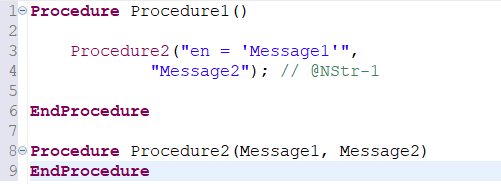
-
-
Search for References to an Object
We have optimized the algorithm for displaying found occurrences in the Search panel when this panel contains the results of searching for references to an object. Now the calculation of found occurrences runs when moving through the branches of the tree only for the current branch. Previously, it was executed immediately for all branches when opening the panel, which could lead to noticeable delays.
-
Extraneous Project Changes
We have made a number of improvements to reduce the number of spurious project changes that occur during editing. Usually, such changes were associated with a change in the order of elements in collections in which this order has no applied meaning and does not affect the operation of the application.
Fixed Bugs 2024.1.0
1C:EDT
-
Incorrect sorting by the Location Field in the Tasks panel #976.
-
NullPointerException in compare-merge when pressing the key combination: Ctrl+Shift+- #1191
-
Selection in the filter by subsystems does not function during comparison / merging #1143.
-
The font is not saved when editing in conditional formatting #1141.
-
EDT silently spoils the data composition schema if something is missing in the extension #1209.
-
Import of external data processor with the standalone server enabled #1282.
-
Incorrect filling of the search history of the navigator panel #1229.
-
When creating an object command, it is proposed to open an object form with an incorrect name #1237.
-
The metadata object command is not removed from the subsystem command interface #1238.
-
Incorrect grouping of search results in projects of external reports and processing #1260.
-
The extension application module does not support After directives #1265.
-
Dragging a global command to the command bar menu results in a configuration error. #1320.
-
Incorrect export of XML schema if only the Base Type property is set #1323.
-
The number length limit in the property palette does not function #1343.
-
There is no way to suppress the error "Optional parameter is located before required" #1354.
-
Silently fails to activate the project context if JAVA 19 Orcale is installed #1402.
-
Renaming a local variable spoils comments throughout the configuration #1412.
-
Debugging an application on a remote infobase has stopped functioning#1434.
-
Error updating the infobase. Extended standard command bar commands. #1453
-
Edt hung when validating when I added a new module and moved one function to it. #1379.
-
The Query Wizard does not allow adding a field to the aggregated field of a grouping #1345.
-
When choosing a procedure that handles a form or its element event, a suitable procedure that already exists in the module is not offered.
-
When editing strings in different languages, several hyperlinks are substituted instead of one.
-
It is not possible to load the infobase into the standalone server application (context menu - Load infobase...).
-
Updating the configuration of the infobase results in no users with administrative privileges in it. Such an error could occur when using a standalone server.
-
Unable to change the Data Separation property of a shared attribute in an application for a mobile platform.
-
Extra command Revert Commit in the context menu of the History panel.
-
Improved incremental updating of the configuration extension from the infobase.
-
The number of fields generated in the dynamic list query, in some situations, differs from the number generated by Designer.
-
If you cancel an arbitrary query in the dynamic list, the query is not cleared.
-
Errors when editing strings in different languages in the data composition system.
-
When changing the location of the application from the infobase to the standalone server and back, the sign of using this application by default is not saved.
-
When importing, the empty value of the Compatibility Mode Version property of the configuration extension is incorrectly translated.
-
When a subsystem is excluded from the command interface, it is not excluded from the order of subsystems of the parent.
-
Window sizes for dynamic list settings are not saved.
-
Form event handler procedures are not always inserted into the areas provided for by development standards.
-
In some cases, the form is not displayed in the form editor preview window.
-
When switching to another Git branch, in some cases, the Applications and Development panels were not updated.
-
The 1C:EDT CLI command line interface, in some situations, could issue a false message Command not found.
-
In search results, in some cases, the found text fragment is not shown.
-
The composition of commands in the form editor is not updated. This error occurred if the type of the command parameter automatically placed in the form is a defined type, and the type of the defined type changes.
-
When switching to another Git branch, in some cases, a running Designer agent process could remain, which prevented access to the "released" infobase.
-
In the 1C:EDT CLI command line interface in -command mode, regular expressions are incorrectly passed as command arguments.
-
In some situations, the 1C:EDT CLI command line interface could misinterpret the --version argument.
-
1C:EDT freezes when showing a large number of markers in the Configuration Errors panel.
-
Extra fields are displayed in the dynamic list. This error could occur in some situations.
-
Error when updating the configuration of the infobase from the project: ... No display for type...".
-
Error when updating the configuration of the infobase from the project: ... XML data conversion error...". This error could occur when partially loading changes into the infobase.
-
The external data processor file is deleted if you copy a form from another external data processor into it.
Fixed Bugs 2024.1.1
1C:EDT
-
Debugging an application on a remote infobase has stopped functioning#1434.
-
In the 1C:Enterprise Language Editor, the Show Version Information command has disappeared.
-
Comparison and merging of pictures in layouts of the Graphical Schema type are not supported. Source: https://partners.v8.1c.ru/forum/topic/2170189#m_2170189.
-
In the dynamic list editor, the delete, move, and copy commands do not function in the dynamic list settings for parameters and calculated fields.
-
Error when clicking Save Configuration to File... in the Infobases panel. Source: https://t.me/e1c_edt/102082.
-
Error "Invalid URI host" when starting debugging on a file-mode infobase.
-
1C:EDT freezes when switching between Git branches.
If You Encounter a Problem
If you encounter a problem during operation or if you have doubts that 1C:EDT runs as desired, you can take the following steps.
Status Panel
If you think nothing is happening, open the Status panel or look in the lower right corner of the main window. Perhaps 1C:EDT is running operations, you just don't notice it.
The Status panel shows the progress of long-running background operations: when importing configurations, when building a project model, and in other cases.
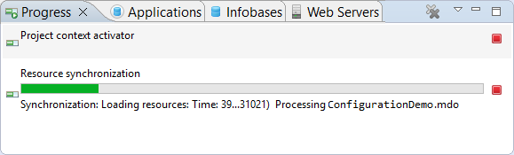
-
Opening the Status Panel There are several ways to open the Status panel:
-
 removes the operation from the panel.
 -
 removes all completed operations from the panel.
 in the lower right corner of the main window.
 interrupts the operation.
Known Issues and Their Solutions
If you encounter an unclear message, see the list of known problem situations.
Editor Malfunctions
If you think one of the editors is not functioning correctly, the following sequence of steps may help you:
-
Click Close All in the context menu on the title bar of any editor. All editors will be closed.
-
Click Reset in the context menu on the open perspective in the perspective bar. The standard arrangement of panels will be restored and they will be reopened.
Project Cleaning
One of the reasons for incorrect operation may be violations in the project model. You can rebuild the project.
-
Click Project > Clean....
-
If you want to clean only some projects (this is faster):
-
Uncheck the Clean All Projects checkbox.
-
Check the boxes for the projects you want to clean.
-
-
Click Clean.
The projects will be cleaned and their internal model will be rebuilt, as when importing a configuration from an infobase:
-
Calculation of calculated data
-
Calculation of search and other indexes
-
Model validation
Restarting 1C:EDT
Another reason for incorrect operation may be violations in the operation of services serving project models. In this case, restarting 1C:EDT may help.
To do this, click File > Restart.
Error Log for Technical Support
To reproduce and analyze incorrect operation, technical support may request an error log from you.
-
1C:EDT To generate this file for 1C:EDT:
-
Open the Error Log panel.
-
Click
 (Export Log) in its command bar.
The same error log is contained in the .log file in your current workspace, in the .metadata directory.
-
1C:EDT Start To get .log files for 1C:EDT Start:
-
Open the 1C:EDT Start settings.
-
In the line General > Application Log, click the icon
 .
.
-
-
1C:EDT CLI Command Line Interface Dumps
The command line interface has option -timeout, which sets the maximum time allowed to execute commands. If execution does not finish within the specified time, it is terminated, and a thread dump is recorded to help diagnose the cause of the issue.
Dumps are written to your current workspace in the .metadata directory. They have names:
1cedtcli-thread-dump.<pid>.<index>.txtwhere:
-
<pid> is the process identifier.
-
index is the sequence number of the dump (in interactive mode, one process can generate more than 1 dump).
When writing dumps, 1C:EDT displays their full names on the command line, and also writes these names to the error log.
If 1C:EDT Freezes
If 1C:EDT does not respond to your actions for a long time and there are no visible notifications that some long action is running, then we can assume that 1C:EDT is frozen. In this case, to investigate errors, we recommend that you immediately, without waiting for a response from the developers, take a thread dump and a memory dump to transfer them to technical support.
Thread Dump
Usually, a dump of application execution threads is enough to investigate freezes. To take a thread dump, you can use the standard jstack utility that is part of the Java Development Kit (JDK). Run the following command:
jstack -l 22668 > threaddump.txtHere 22668 is the PID (process identifier) of the javaw.exe process. You can find it through the task manager, depending on the operating system.
You can also get the PID from the command line or terminal:
Windows 10
tasklist /fi "IMAGENAME eq javaw.exe"Linux
ps aux | grep 1cedtAs a rule, a dump of the javaw.exe process is required, but if the 1C:EDT launch configuration file (1cedt.ini) has not been changed, then a dump of the original 1cedt.exe process is needed.
The path and file name of the dump file in the example above is specified after the > character. If only the file name is specified, the dump will be saved in the directory from which the command line or terminal was launched.
If the dump command runs successfully, no additional messages will appear. If a problem occurs, an error message will be displayed. For example, if no PID is found, the message will be:
<PID>: no such processIf running the previous jstack -l command results in a connection failure, run the utility with the -F flag:
jstack -F 22668 > threaddump.txtSend the resulting threaddump.txt file (thread dump) to technical support.
Important: Run the jstack utility as the same user as the inspected application.
Tip: The documentation for the jstack utility is available here.
Memory Dump
To take a memory dump, you can use the standard jmap utility that is part of the Java Development Kit (JDK). Run the following command:
jmap -dump:format=b,file=memorydump.hprof 22668Here 22668 is the PID (process identifier) of the javaw.exe process. You can find it through the task manager, depending on the operating system.
You can also get the PID from the command line or terminal:
Windows 10
tasklist /fi "IMAGENAME eq javaw.exe"Linux
ps aux | grep 1cedtAs a rule, a dump of the javaw.exe process is required, but if the 1C:EDT launch configuration file (1cedt.ini) has not been changed, then a dump of the original 1cedt.exe process is needed.
The path and file name of the dump file in the example above is specified in the file= parameter. If only the file name is specified, the dump will be saved in the directory from which the command line or terminal was launched.
If the dump command runs successfully, the following message will be displayed:
Heap dump file createdIf a problem occurs, an error message will be displayed. For example, if no PID is found, the message will be:
Exception in thread "main" java.io.IOException: no such processIf running the previous jmap -dump command results in a connection failure, run the utility with the -F flag:
jmap -dump:format=b,file=memorydump.hprof -F 22668Send the resulting memorydump.hprof file (memory dump) to technical support.
Tip: The documentation for the jmap utility is available here.
How to Close a Frozen 1C:EDT
When all the necessary dumps are received, you can close 1C:EDT. If this cannot be done interactively, you can either use the task manager, depending on the operating system, or terminate the process by running the following command:
kill -f 22668Here 22668 is the PID (process identifier) of the 1C:EDT process.
Error Log Panel
The Error Log panel shows all warnings and errors written by Eclipse plugins to the log file. This log file is located in the workspace's .metadata directory.
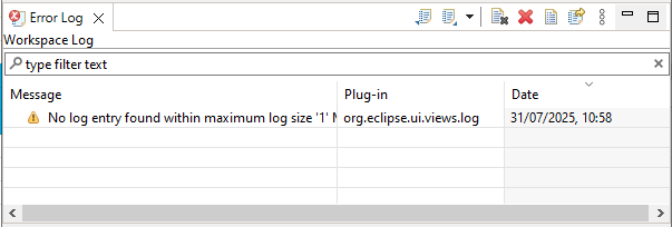
The panel is populated with data automatically. There is a search field above the list of events. It can be used to select events that contain a specific string fragment.
Opening the Error Log Panel
Click Window > Show View > Other... > General > Error Log in the main window menu.
Legend
 Information
 Warning
 Error
Error
Columns
- Message is the text of the error message, warning, or message.
- Plugin is the plugin that caused the message to be generated.
- Date is the date and time the message was generated.
Mouse Actions
- A single click on a column header sorts the list by that column. If the list is already sorted by this column, the sort direction changes.
- Double-clicking a row opens a dialog with detailed information about the event.
Command Bar
- (Export Log) exports the error log to a text
.logfile.  (Import Log) imports an error log from a text
 .logfile. (Clear Log Window) clears the Error Log panel. The main
 .logfile is not deleted. (Delete Log) deletes the main
 .logfile and clears the Error Log panel. (Open Log) opens the main
 .logfile in a text editor. (Restore Log) restores records in the Error Log panel from the main
 .logfile. (Show Menu) opens a drop-down menu containing additional commands for the panel:
- Group submenu:
- Session groups records by sessions.
- Plugin groups records by plugins.
- No cancels record grouping.
- Filters... opens a dialog that lets you display only specific messages instead of all messages. Filtering by event type and session is available. You can also limit the number of displayed messages and the maximum log size.
- Activate on New Events opens the Error Log panel over other panels in its group when a new event occurs, if the checkbox is selected.
- Show Text Filter displays a search field above the event list, if the checkbox is selected.
- Group submenu:
Context Menu
- Copy copies information about the selected event to the clipboard.
- Clear Log Window clears the Error Log panel. The main
.logfile is not deleted. - Delete Log deletes the main
.logfile and clears the Error Log panel. - Open Log opens the main
.logfile in a text editor. - Restore Log restores records in the Error Log panel from the main
.logfile. - Export Log exports the error log to a text
.logfile. - Import Log imports an error log from a text
.logfile. - Export Record... exports information about the selected event to a
.logfile. - Event Details opens a window to view detailed event information.
1C:EDT Bug Tracker
The address of the bug tracker is https://github.com/1C-Company/1c-edt-issues.
On this bug tracker, you can register bugs and suggestions related to 1C:EDT.
The 1C:EDT interface has a button ![]() (Report an Issue) that lets you quickly report a bug to the bug tracker without leaving your current context.
(Report an Issue) that lets you quickly report a bug to the bug tracker without leaving your current context.
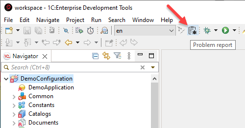
To use this feature you need to have an account on the GitHub portal as well as an access token.
This data must be specified in the send report settings Window > Preferences > Error Reporting.
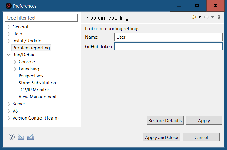
Field descriptions for the error report form:
-
Title. Give a brief description of what happened.
-
Description. Describe in detail, step by step, what led to the incorrect behavior of the system. Including:
-
What you did
-
What expected to receive
-
What was the result
-
-
Attach screenshot. By default the checkbox is checked and a screenshot of 1C:EDT taken at the time of clicking
 (Report an Issue) is added to the report.
 -
Attached files. You can attach any files that will help in analyzing the error to the report. These files will be sent to the developers directly and will not be attached to the task in GitHub.
Chapter 2. Using with the 1C:EDT Start Launch and Update Application
1C:EDT Start is a launch and update application. It is part of 1C:EDT and allows you to manage all projects and versions of 1C:EDT installed on your computer.
Project in 1C:EDT Start refers to a workspace and the development environment used to create the application contained in that workspace.
The development environment can be a specific version of 1C:EDT (for developing 1C:Enterprise applications) or a particular Eclipse build (for developing plugins for 1C:EDT).
This setup enables you to choose the appropriate development environment for each application being developed and configure specific settings for it, if needed.
1C:EDT Start supports authorization on the 1C:ITS portal. When creating a project, you can select one of the environments published on the portal. This environment will be automatically downloaded and installed on your computer. It can then be used for other projects.
With authorization on the 1C:ITS portal, you can also update installed development environment releases automatically with a single button click. All project settings associated with the updated release will be preserved.
If you do not have an internet connection or authorization on the 1C:ITS portal is unavailable, you can still use 1C:EDT Start to manage your projects. In this case, you will need to install and update development environments manually using offline installation packages obtained on an external storage device.
Managing Projects in 1C:EDT Start
All Projects
The list of all projects is located on the main page of 1C:EDT Start and is automatically displayed upon startup. For each project, the name, the development environment in use, and the last run date are displayed.
Projects are sorted by the time of their last run, with recently run projects at the top and older ones at the bottom.
Stopped projects have a triangle on their icon, indicating that the project can be launched. Running projects do not have this triangle and instead display Running instead of the last run date.
When you hover over a project, icons for available actions appear: Delete, Open Folder, Settings.
Create a New Project
-
Click New Project.
-
Select the project type and the development environment version:
-
If you want to use the latest version of the development environment (recommended), hover over the project type and click the checkbox
 or the downward arrow
  . The checkbox appears if the recommended version is already installed. The arrow appears if the version will be downloaded and installed during project creation.
 -
If you prefer to use a specific version of the development environment rather than the recommended one, hover over the project type and click the right arrow
 to open the list of available versions. Select the desired version.
-
-
Enter the project name and click OK.
-
If needed, change the default location for your project (1C:EDT Workspace) suggested by 1C:EDT Start.
-
Click Add Project.
1C:EDT Start will create the workspace. If the selected version of the development environment is not installed, 1C:EDT Start will begin downloading and installing it. A progress indicator shows you the status of the process.
-
During the download, 1C:EDT Start may ask you to accept the license agreements. Click Accept All.
If desired, uncheck Remember Accepted Licenses to accept or decline each license individually.
-
After completing all operations, the new project will appear in the list in a stopped state.
Remember: If you installed a new development environment release during project creation, configure it.
Add an Existing Workspace to the Project List
-
Click New Project.
-
Hover over the 1C:Enterprise Application type and click the right arrow
. -
Select the development environment release you previously used to work with the workspace.
-
Enter the project name and click OK.
-
In the Project Location field, specify the path to the existing workspace.
1C:EDT Start will detect that an old project exists in the directory and notify you about it.
-
Click Add Project.
If the selected version of the development environment is not installed, 1C:EDT Start will begin downloading and installing it. A progress indicator shows you the status of the process.
-
During the download, 1C:EDT Start may ask you to accept the license agreements. Click Accept All.
If desired, uncheck Remember Accepted Licenses to accept or decline each license individually.
-
After completing all operations, the new project will appear in the list in a stopped state.
If you were working with this workspace in 1C:EDT at that moment, the new project in the list will be marked as running.
Find a Project in the List
The project list can be large. To find a project by part of its name, click the magnifying glass  and enter part of the name.
Matching projects will be displayed, with the entered fragment highlighted in their names.
Run and Stop a Project
Stopped projects have a triangle on their icon, indicating that the project can be launched.
Run a Project in 1C:EDT Start
Click the triangle icon on the project.
Stop a Project in 1C:EDT Start
Close the instance of 1C:EDT running for the project.
Find Project Files on Disk
To locate the files of a project on the disk, hover over the desired project and click the folder icon  . The file explorer will open the folder containing the project files.
Project Settings
Open Project Settings
Hover over the desired project and click the gear icon 
Close Project Settings
Click the cross icon  in the header. Modified values will be saved automatically.
Change the Project Name
Change Project Launch Parameters
If specific launch parameters are set for a project, they will be used instead of the default parameters of the development environment.
Open the project settings and scroll to the Launch section.
Java Virtual Machine Path
In the Java VM field, specify the path to the Java Virtual Machine. If you installed the Liberica JDK installation package in the standard way, specify the following paths:
Windows
C:\Program Files\BellSoft\LibericaJDK-11-Full\binLinux
/usr/lib/jvm/bellsoft-java11.x86_64/binmacOS
/Library/Java/JavaVirtualMachines/liberica-jdk-11.0.4/Contents/Home/binMaximum Allocated Memory
Importing large standard configurations like 1C:ERP can take a long time and require a significant amount of RAM. Therefore, if you plan to perform such an import, increase the amount of memory available to the Java Virtual Machine.
In the Maximum Allocated Memory field, select 8 GB.
Temporary Directory Location
Large standard configurations can contain objects with long names.
To load into 1C:EDT, the configuration is first unloaded from the infobase to a temporary directory in a folder hierarchy. This hierarchy repeats the structure of the configuration. As a result, the full path to some .xml configuration file may exceed the limits imposed by the operating system, and the configuration import will end with an error.
To avoid this, place the temporary directory that 1C:EDT uses for importing and exporting configuration files as close to the root of the disk as possible.
- Click Edit as Java VM parameters....
- In the Java VM arguments field, add the line:
-Djava.io.tmpdir=C:\tmpReplace C:\tmp with the temporary file directory you want to use.
Interface Language
1C:EDT uses the operating system's language settings for its interface.
If you are using an English-language operating system and want to interact with 1C:EDT using Russian, in the Interface Language field, select Russian.
Change the Development Environment Release
-
Open the project settings.
-
Scroll down to the Development Environment section.
-
Click the pencil icon
next to the selected development environment. -
Choose an installed or available release of the development environment.
-
Close the project settings.
If you select a non-installed development environment, it will be downloaded and installed when the project is launched.
Delete a Project
Hover over the project and click the trash bin icon  .
.
-
If you want to delete the project from both the list and the disk, click Confirm.
-
If you want to delete the project only from the list, uncheck Also delete the project from disk and click Confirm.
Managing Development Environments in 1C:EDT Start
All Development Environments
Opening Development Environments
- Click the gear icon
 in the 1C:EDT Start header.
 - Click the line in the Development Environments section.
The Installed section lists installed releases down to the patch level.
Versions installed without the Internet are also listed here. These are marked with a triangle  , indicating that updating these releases via 1C:EDT Start is not possible.
The Available for Installation section lists the releases you can install for each development environment. Such lines contain a rightward arrow  . Clicking this line opens the list of releases, where you can select one.
If only one release is available for installation, the line contains a downward arrow  . Clicking this line will immediately begin downloading and installing the development environment.
Installing a New Release of a Development Environment
-
Open the development environments.
-
In the Available for Installation section, click the right arrow
to open the list of available releases. -
Select the desired release.
-
1C:EDT Start will switch to the list of development environments and begin downloading and installing the new release. A progress indicator shows you the status of the process.
Remember: Configure the launch parameters for the new release.
Once the development environment is installed, you can assign it to an existing project.
Fastpath: If you want to immediately use a new, not yet installed development environment release for a project, select it in the project settings. It will be automatically downloaded and installed when you launch the project.
Updating a Development Environment
1C:EDT Start notifies you about new releases. If a new version of an installed release is available, you can automatically update it in several ways.
Updating from a Notification
- Open the notifications.
- In the notification about the release of the required version, click Install.
Updating from a Development Environment
- Open the development environments.
- Hover over the version with the What's New... note and click the curved arrow
The installed release will be updated, and all projects using it will run on the new version of this release.
Development Environment Settings
Opening Development Environment Settings
- Open the development environments.
- Hover over the desired installed development environment and click the gear icon

Closing the Development Environment Settings
Click the arrow  or the cross
  in the header. Modified values will be saved automatically.
Modifying the Launch Parameters of the Development Environment
Open the development environment settings.
Java Virtual Machine Path
In the Java VM field, specify the path to the Java Virtual Machine. If you installed the Liberica JDK installation package in the standard way, specify the following paths:
Windows
C:\Program Files\BellSoft\LibericaJDK-11-Full\binLinux
/usr/lib/jvm/bellsoft-java11.x86_64/binmacOS
/Library/Java/JavaVirtualMachines/liberica-jdk-11.0.4/Contents/Home/binMaximum Allocated Memory
Importing large standard configurations like 1C:ERP can take a long time and require a significant amount of RAM. Therefore, if you plan to perform such an import, increase the amount of memory available to the Java Virtual Machine.
In the Maximum Allocated Memory field, select 8 GB.
Temporary Directory Location
Large standard configurations can contain objects with long names.
To load into 1C:EDT, the configuration is first unloaded from the infobase to a temporary directory in a folder hierarchy. This hierarchy repeats the structure of the configuration. As a result, the full path to some .xml configuration file may exceed the limits imposed by the operating system, and the configuration import will end with an error.
To avoid this, place the temporary directory that 1C:EDT uses for importing and exporting configuration files as close to the root of the disk as possible.
- Click Edit as Java VM parameters....
- In the Java VM arguments field, add the line:
-Djava.io.tmpdir=C:\tmpReplace C:\tmp with the temporary file directory you want to use.
Interface Language
1C:EDT uses the operating system's language settings for its interface.
If you are using an English-language operating system and want to interact with 1C:EDT using Russian, in the Interface Language field, select Russian.
Deleting a Development Environment
-
Open the development environments.
-
Hover over the installed development environment and click the trash can icon
 .
. -
Click Confirm.
Using 1C:EDT Start
Launch 1C:EDT Start
1C:EDT Start can be launched in several ways:
Option 1. Use the shortcut 1CEDT Start on the desktop (Windows and Linux).
Note: A large number of incompatible shells (desktop environments) have been created for Linux. This affects the process of creating shortcuts for installed software. The installer follows the Desktop Menu Specification by FreeDesktop. More information is available here. It has been tested on Gnome 3 and KDE 5.
Option 2. Use the command Start > 1C Enterprise Development Tools > 1CEDT Start (Windows), or use the 1CEDT Start command in Launchpad (macOS).
Option 3. Run the executable file 1cedtstart from the home installation directory.
With a standard installation, this file is located in the following directories (your 1C:EDT Start version may differ from the one listed here):
Windows
%ProgramFiles%\1C\1CE\components\1c-edt-start-0.6.0+244-x86_64\1cedtstart.exeLinux
/opt/1C/1CE/components/1c-edt-start-0.6.0+244-x86_64/1cedtstartmacOS
/Applications/1C/1CE/components/1c-edt-start-0.6.0+244-x86_64/1cedtstart (0.6.0+244).appHide and Open 1C:EDT Start
Hide 1C:EDT Start
Clicking the close button minimizes 1C:EDT Start to the taskbar. This is its default behavior.
Open 1C:EDT Start
To restore 1C:EDT Start from the minimized state, click Open in its context menu.
Exit 1C:EDT Start
In the taskbar, select Exit from the 1C:EDT Start context menu.
Operate Through a Corporate Proxy Server
1C:EDT Start supports operation through a corporate proxy server on Windows and Linux. To enable this, ensure that the proxy server settings are correctly configured in the operating system.
Windows
To configure proxy server settings on Windows 10, go to Start > Settings > Network & Internet > Proxy.

After making changes, restart 1C:EDT Start.
Linux
On Ubuntu 18.04, proxy server settings are specified in the following environment variables:
HTTP_PROXYhttp_proxyNO_PROXYno_proxyHTTPS_PROXYhttps_proxy
To view their values, use the command:
env | grep -i proxyTo configure proxy server settings, navigate to Settings > Network > Network Proxy.

After making changes, restart 1C:EDT Start.
Individual Proxy Server Settings
If you need proxy settings that differ from the system defaults or require using a corporate proxy with authentication, configure them as follows:
- Open the 1C:EDT Start settings.
- Scroll to the Proxy Settings section.
- Enable the option Manually Specify HTTP Proxy.
- Enter the values for Host, Port, Username, and Password.
- Close the 1C:EDT Start settings.
Authorization on the 1C:ITS Portal
Authorization on the ITS portal is required to automatically install development environments and receive updates for them.
The icon in the 1C:EDT Start header indicates your authorization status on the 1C:ITS portal:
-
Authorized
 .
. -
Not authorized
 .
.
You can click this icon at any time to sign in or sign out of your account on the 1C:ITS portal.
1C:EDT Start requests authorization automatically at startup. If you do not have an internet connection or cannot sign in to the 1C:ITS portal, you can decline authorization.
In this case, you will continue to use the application without authorization.
Using 1C:EDT Start without authorization on the 1C:ITS portal is acceptable in situations where you do not have internet access. However, without authorization, you will not be able to:
-
Automatically install development environments (details). To install a new environment, you will need to obtain an offline installation package on a storage device and install it manually.
-
Automatically update development environments (details). Updating an installed environment will only be possible by installing a new version from an offline installation package. You will also need to transfer the settings, plugins, and other data from the old version to the new one.
Size and Position of 1C:EDT Start
You can adjust the size and position of the 1C:EDT Start window:
-
The window can be resized vertically.
-
Double-clicking the window header expands it to the full height of the screen. Double-clicking again minimizes it to the smallest height.
-
The window's position on the screen and the screen it is displayed on (if multiple screens are used) are saved for subsequent launches of 1C:EDT Start.
-
The height of the window is also saved for future launches.
Notifications
1C:EDT Start notifies you of new development environment versions:
- The application icon in the taskbar displays a red dot

- The 1C:EDT Start header shows a bell icon
 , indicating the number of unread notifications
Open All Notifications
Click the bell icon in the 1C:EDT Start header.
Update a Release from a Notification
If the notification is about a new version of an installed release, it will include an Update button. Click it to update the release.
Delete a Single Notification
Click the cross icon  on the notification.
Delete All Notifications
Click Clear All.
Settings for 1C:EDT Start
Open Settings
Click the gear icon  in the header.
Close Settings
Click the cross icon in the header. Modified values will be saved automatically.
Dark Theme
1C:EDT Start can use a light or dark interface theme. By default, the light theme is enabled after installation.
To enable the dark theme, follow these steps:
-
Open the 1C:EDT Start settings.
-
In the field General > Application Theme, enable the toggle switch.
-
Close the 1C:EDT Start settings.
To revert to the light theme, disable the same toggle switch.
For instructions on enabling the dark theme in 1C:EDT, read here.
Change the Path to Projects
-
Open the 1C:EDT Start settings.
-
In the field General > Path to Projects, enter the new path.
-
Close the 1C:EDT Start settings.
Change the Path to Development Environments
To change the default directory where development environments are stored, follow these steps:
-
Open the 1C:EDT Start settings.
-
In the field General > IDEs Path, enter the new path.
-
Close the 1C:EDT Start settings.
Program Version of 1C:EDT Start
To find out the version of 1C:EDT Start, follow these steps:
-
Open the program settings.
-
Click About.
Application Log
Technical support may require log files (.log) to analyze issues with 1C:EDT Start. To open the directory containing these files, follow these steps:
-
Open the 1C:EDT Start settings.
-
In the line General > Application Log, click the icon
.
Statistics Collection and Reporting
1C:EDT automatically collects error statistics and usage information for various features. This information is aggregated and sent to a monitoring service for analysis. The monitoring service is hosted on 1C's infrastructure (details).
By default, this mechanism is enabled, but it can be disabled. To do this:
-
Open the 1C:EDT Start settings.
-
Scroll down the settings and disable the toggle switch General > Enable Statistics Collection and Reporting.
-
Close the 1C:EDT Start settings.
Shared Plugin Storage
By default, 1C:EDT Start saves plugins in a shared storage location when installing development environments. This means that if two development environments use the same plugin version, they will share the plugin from this storage.
You can disable the shared plugin storage, and then all plugins for any newly installed development environment will be saved to that environment’s directory. When the development environment is removed, all its plugins will also be deleted, freeing up disk space.
To disable shared plugin storage, follow these steps:
-
Open the 1C:EDT Start settings.
-
In the field Advanced > Use Shared Plugin Storage, disable the toggle switch.
-
Close the 1C:EDT Start settings.
Installation for All Users
By default, 1C:EDT Start installs development environments for the current user who is running it.
If multiple users on the same computer require the same development environments, you can install them for all users at once. To do this:
-
Open the 1C:EDT Start settings.
-
In the field General > IDEs Path, specify a folder accessible to all users of the operating system.
As a result, other users will have access to the installed development environments.
-
Scroll down to the Advanced section.
-
Enable the toggle switch Installation for All Users.
As a result, information about the installed development environments will be saved in a shared registry, and 1C:EDT Start launched by other users will detect it.
-
Close the 1C:EDT Start settings.
Development environments installed afterward will be accessible to all operating system users.
Chapter 3. 1C:EDT Configuration
Workspace
A workspace is a folder where everything you develop in 1C:EDT is stored. Additionally, some 1C:EDT settings that you may modify during application development are stored in the workspace.
You can have multiple workspaces. It is recommended to use a single workspace for developing one 1C:Enterprise application with multiple extensions, reports, and data processors.
If you use 1C:EDT Start, each of its projects is placed in a separate workspace. By launching a specific project from 1C:EDT Start, you are launching 1C:EDT with the associated workspace.
If you launch the 1cedt executable file (for example, after an offline installation), 1C:EDT prompts you to select a workspace.
Finding the Workspace Location in 1C:EDT Start
The workspace is the project location in 1C:EDT Start.
To locate the files of a project on the disk, hover over the desired project and click the folder icon . The file explorer will open the folder containing the project files.
Finding the Workspace Location in 1C:EDT
The workspace location is specified in the following parameter: Window > Preferences > General > Workspace > Show full path to workspace. This path can be selected and copied to the clipboard.
Switching to Another Workspace in 1C:EDT
If 1C:EDT is already running, you can switch to another workspace without closing it. To do this, click File > Switch Workspace....
Executable Files Directory
In some cases, you may need to access the directory containing the 1C:EDT executable files, for example:
-
For configuring an offline-installed version of 1C:EDT.
-
For using the 1C:CLI command-line interface.
Installation from the Main Installation Package
If 1C:EDT was installed using the main installation package, the path to the executable files of all 1C:EDT versions is specified in the settings of the 1C:EDT Start application:
-
Open the 1C:EDT Start settings.
-
Copy the path specified in the field General > IDEs Path.
-
Open this path in the file explorer.
With the standard installation, all development environments are placed in the following directory:
%LOCALAPPDATA%\1C\1cedtstart\installationsFor example, in Windows 10, this would be:
C:\Users\Test\AppData\Local\1C\1cedtstart\installationsThus, the executable files directory for 1C:EDT version 2023.2 would be:
C:\Users\Test\AppData\Local\1C\1cedtstart\installations\1C_EDT (Lite) 2023.2_\1cedtOffline Installation
If 1C:EDT was installed offline, the path to the executable files for all versions of 1C:EDT is specified in the Installation Home Directory field of the "Installer" (more details).
With the standard installation, all development environments are placed in the following directory:
%ProgramFiles%\1C\1CE\componentsFor example, in Windows 10, this would be:
C:\Program Files\1C\1CE\componentsThus, the directory containing the executable files for 1C:EDT version 2023.1 would be located here:
C:\Program Files\1C\1CE\components\1c-edt-2023.1.0+282-x86_641C:EDT Appearance
Setting Up the Main Menu and the Main Window Command Bar
Showing and Hiding Menu Items and Buttons of the command bar
You can hide or display specific elements of the main menu and buttons in the Main Window Command Bar.
To hide a menu item or button,
-
Open the perspective you want to customize.
-
Click Window > Perspective > Customize Perspective....
-
and navigate to one of the tabs: Toolbar Visibility or Menu Visibility.
-
Locate the element you want to hide by
-
expanding the hierarchy of menus or buttons to find the specific item.
-
Select the checkbox Filter by action set to display a list of action sets providing commands and buttons. Choose the desired action set and proceed to the window containing the menu or button hierarchy of this action set.
-
-
To get additional information about a menu item or button, hover over it and wait for the tooltip to appear, which contains:
-
A description of the element’s functionality.
-
The name of the action set providing this element (click the link to open this action set on the Action Set Availability tab).
-
The keyboard shortcut assigned to the action (click the link to open this command in the Keys parameter group).
-
-
Uncheck the box for the selected menu item or button.
-
Click OK.
Using the tooltip, you can navigate to the Action Set Availability tab, where you can disable the entire action set if you want to hide all menu items, buttons, and shortcuts it provides.
To display a hidden menu item or button, follow the steps above, except in step 6, make sure to select the checkbox for the desired menu item or button.
If the item you want to make visible is grayed out, it means the action set providing this element is unavailable. First, enable the action set itself by using the link in the tooltip. To quickly navigate to it, use the link available in the tooltip of the selected element.
Rearranging Sections of the command bar
Sections of the Main Window Command Bar can be rearranged. Sections are separated by thin dashed lines.
-
Ensure the command bar is unlocked. When the command bar is unlocked, thin dashed lines appear, separating the sections from each other.
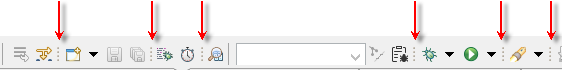
If it is locked, click Unlock Toolbars in the context menu of the panel.
-
Position the mouse pointer at the thin dashed line to the left of the section you want to move. The cursor will change shape, indicating that the section can be grabbed.
-
Press and hold the left mouse button to grab the section.
-
Move it to the desired position and release the mouse button to place it.
-
To prevent accidental changes to the command bar, lock it again by clicking Lock Toolbars in the context menu.
Configuring Menu and command bar Contents
All menu items and buttons are grouped into several action sets. You can choose which action sets’ commands will be displayed in the menu and command bar. If an action set is made unavailable, all its commands will disappear from the 1C:EDT interface.
To configure action set availability,
-
open the perspective you want to customize.
-
Click Window > Perspective > Customize Perspective....
-
Go to the Action Set Availability tab.
-
Select the set whose commands you want to show or hide.
-
Check or uncheck the box next to this set.
-
Click OK.
Main Window Command Bar
The Main Window Command Bar contains the following commands.
-
 (New) Opens a dialog allowing you to create new resources using one of the available wizards.
 -
(Save) Saves changes made in the active editor panel.
-
 (Save All) Saves changes made in all open editor panels.
 -
 (Update Developed Applications) Updates the database configuration in the infobase associated with the project selected in the Navigator panel. This is equivalent to the Update Database Configuration command in 1C:Enterprise Designer (learn more).
 -
 (Skip All Breakpoints) Marks all breakpoints as inactive. Inactive breakpoints do not stop program execution during debugging, regardless of whether they are enabled or not. This command is useful when temporarily skipping step-by-step debugging without changing or deleting breakpoints.
 -
 (Resume) Resumes the execution of the module after stopping at a breakpoint.
 -
 (Pause) Stops the module execution at the current statement and allows debugging to begin from the next executable line. This command is useful, for example, when analyzing a "looping" module or for stopping execution when the location of the code being executed as a result of an action in the application solution is unknown.
 -
 (Terminate) Stops module execution and ends the current debug session. Events BeforeExit and OnExit will not be triggered.
 -
 (Disconnect) Disconnects the debugger from the debug target. The command is active when the Debug panel highlights a debug target
  .
. -
 (Join) Connects the debugger to the debug target. The command is active when the Debug panel highlights a debug target .
 -
 (Configure Debug Targets) Clicking the list button allows you to select the types of debug targets that will be connected automatically. Clicking the gear icon allows you to create filters for debug targets that will be automatically connected. This command is active when the Debug panel highlights an application debug structure
  .
. -
 (Step Into) Executes the current instruction and moves to the next. If the current instruction contains a method call, step-by-step execution of that method begins.
 -
 (Step Over) Executes the current instruction and moves to the next. If the current instruction contains a method call, that method executes in full (not step-by-step).
 -
 (Step Return) Executes the current instruction, all instructions up to the end of the current method, and moves to the instruction from which the current method was called.
 -
 (Drop to Frame) Not used when developing 1C:Enterprise applications. Re-enters the selected call stack.
 -
 (Use Step Filters) Not used when developing 1C:Enterprise applications. Enables or disables step filters during debugging.
 -
 (Integrated Debugging) When the button is pressed, the integrated debugging results are displayed in the 1C:Enterprise Language editor. When unpressed, they are not displayed.
 -
 (Performance Meter) If the button is pressed, performance measurement recording is running. When unpressed, the recorded measurement is displayed in the Performance Meter panel.
 -
 (Open Configuration Object) Opens a search dialog, allowing you to find a configuration object by its name prefix and open it in the editor.
 -
 (Editing Language) Indicates which language (from those available in the configuration) corresponds to the strings displayed in the interface properties. Allows you to switch to another language on the fly by selecting it from a dropdown list. This feature enables you to see how a form or command interface fragment will appear in different languages during development.
 -
 (Hide/Show Errors from Base Git Branch) Toggles th<u></u>e visibility of 1C:Enterprise Language errors introduced in the branch selected as the base branch. This helps hide previously existing errors in the project, allowing you to focus on your new development errors.
 -
(Report an Issue) Sends a bug report to the 1C:EDT bug tracker.
-
 (Debug As...) Launches the application in debug mode (about selecting the platform version). The submenu contains commands for quickly launching a specific client application in debug mode.
-
<launch configuration name 1> … <launch configuration name N> Favorites list of debugging configurations. Initially, this list is empty and not shown. You can create a personal list of favorite configurations for debugging applications by selecting Manage Favorites... from this menu.
-
<launch configuration name 1> … <launch configuration name N> Launch configuration history. Automatically populated as you use different launch configurations.
-
Debug As The submenu contains commands for quickly launching specific client applications in debug mode (learn more).
-
1C:Enterprise Web Client Launches the web client in debug mode.
-
1C:Enterprise Mobile Client on Android OS Launches the mobile client in debug mode.
-
Connect to 1C:Enterprise Debug Server Launches the debug server connection configuration.
-
1C:Enterprise Thick Client Launches the thick client in debug mode.
-
1C:Enterprise Thin Client Launches the thin client in debug mode.
-
-
Debug Configurations... Opens the Launch Configuration Editor.
-
Manage Favorites... Opens a dialog for creating and managing the list of favorite debugging configurations.
-
-
 (Run As...) Launches the application contained in the selected project (about selecting the platform version). The submenu contains commands for quickly launching a specific client application.
-
<launch configuration name 1> … <launch configuration name N> Favorites list of launch configurations. Initially, this list is empty and not shown. You can create a personal list of favorite configurations for running applications by selecting Manage Favorites... from this menu.
-
<launch configuration name 1> … <launch configuration name N> Launch configuration history. Automatically populated as you use different launch configurations.
-
Run As The submenu contains commands for quickly launching specific client applications (learn more).
-
1C:Enterprise Web Client Launches the web client.
-
1C:Enterprise Mobile Client on Android OS Launches the mobile client.
-
1C:Enterprise Thick Client Launches the thick client.
-
1C:Enterprise Thin Client Launches the thin client.
-
-
Launch Configurations... Opens the Launch Configuration Editor. The Debug Connection tab will be unavailable (learn more).
-
Manage Favorites... Opens a dialog for creating and managing the list of favorite launch configurations.
-
-
 (Launch Last Tool): Not used in the development of 1C:Enterprise applications.
 -
 (Search) Opens a search dialog. You can use four search scenarios:
-
Searching for configuration objects with restricted search scope based on various criteria.
-
Searching for files by content or name in the workspace or a specific directory.
-
Java Search ().
-
Searching in Git repositories ().
-
-
 (Next Annotation) Moves to the next warning or error marker in the module or the next bookmark in the module.
 -
 (Previous Annotation) Moves to the previous warning or error marker in the module or the previous bookmark in the module.
 -
 (Previous Edit Location) Opens the last edit location in the 1C:Enterprise Language editor.
 -
 (Next Edit Location) Opens the next edit location in the 1C:Enterprise Language editor (after navigating to the previous edit).
 -
 (Back To) Moves to the previous cursor position in the 1C:Enterprise Language editor. With this command, you can, for example, go back after performing a jump to definition of a procedure or function.
 -
 (Forward) Moves forward to the next point in the module navigation history.
 -
 (Pin Editor): Not used in the development of 1C:Enterprise applications.
 -
 (Toggle Occurrence Markers) If the button is pressed, all occurrences of the current identifier (the identifier located under the cursor) are highlighted in the 1C:Enterprise Language Editor. If it is released, they are not highlighted. The highlighting method is configured in the 1C:EDT preferences.
Managing Perspectives in 1C:EDT
Automatic Opening of Perspectives
When 1C:EDT starts, the 1C:Enterprise perspective automatically opens. This is the main workspace for application development.
Other perspectives are designed for different tasks. In some cases, switching to another perspective occurs automatically. For example, when stopping at a breakpoint, 1C:EDT automatically switches to the Debugging perspective.
In other cases, you can manually open the perspective you need. More details can be found in the Manual Opening of Perspectives section.
Perspective Panel
The Perspective panel displays perspectives open in the workspace. It contains a button for opening a new perspective and a set of buttons representing the currently open perspectives.
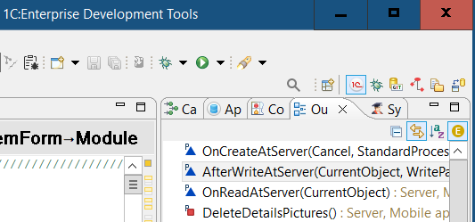
Context menu commands for the active perspective:
Show Icon with Panel Name
By default, perspectives in the panel are represented by their icons. You can change the display method and add the panel name to the icon. To do this, in the perspective panel, click Show Text in the context menu of any perspective.
Manual Opening of Perspectives
To open a new perspective, follow these steps:
-
Click
 (Open Perspective) in the perspective panel.
Note: The same action can be run by clicking Window > Perspective > Open Perspective > Other....
-
Double-click the required perspective to open it.
The opened perspective’s icon will be added to the Perspective panel, allowing quick switching while in another perspective.
Usually, a perspective opens in the same main window. You can change the settings so that it opens in a separate main window. More details can be found in the Opening Method of Perspectives section.
Switching Between Perspectives
Open perspectives are displayed as icons on the perspective panel. When multiple perspectives are open, you can switch between them by clicking on the icons in the perspective panel.
Setting the Default Perspective
The default perspective 1C:Enterprise opens automatically when 1C:EDT starts. When you open a perspective manually, the list of perspectives includes the label "(default)" next to the default perspective.
It may be necessary to change the default perspective if, for example, you have created a custom, more convenient perspective and want it to open automatically when 1C:EDT starts. To change the default perspective, follow these steps:
-
Click Window > Preferences... > General > Perspectives.
-
Select the perspective you want to set as the default and click Set as Default. The "(default)" label will move to the selected perspective.
-
Click Apply and Close.
Opening Method for Perspectives
A perspective typically opens in the same main window you are using. You can change this setting so that a perspective opens in a new main window. To do this:
-
Click Window > Preferences... > General > Perspectives.
-
In the Open a new perspective group, select In a new window.
-
Click Apply and Close.
Modifying a Perspective
Besides modifying the set of commands and buttons on the command bar, you can change the layout and composition of the panels within a perspective. You can:
-
Close an existing panel.
A modified perspective can be saved for future use.
If you want to revert to the default appearance of a perspective, restore it.
Saving a Modified Perspective
To save your modified perspective and use it later, follow these steps:
-
Switch to the perspective you want to save.
-
In the context menu of the perspective panel, click Save As....
Note: You can perform the same action by clicking Window > Perspective > Save Perspective As....
-
Enter a new name for the perspective in the Name field.
-
Click Save.
Deleting a Modified Perspective
You can delete a perspective you have saved (default perspectives included in 1C:EDT cannot be deleted). To do this, follow these steps:
-
Click Window > Preferences... > General > Perspectives.
-
In the Available Perspectives field, select the perspective you want to delete and click Delete.
-
Click Apply and Close.
Restoring a Perspective
To restore a perspective to its default state (for example, after an unsuccessful panel rearrangement), click Reset in the context menu of the perspective panel.
Note: You can also perform this action by clicking Window > Perspective > Reset Perspective.
Closing a Perspective
To close a perspective, click Close in the context menu of the perspective panel.
Note: You can also perform this action by clicking Window > Perspective > Close Perspective.
Panels and Editors
Opening Panels
Perspectives contain a predefined set of panels and editors. To open a panel not included in the current perspective, click Window > Show View > Other....
You can then save the current perspective under a new name and use it later.
Moving Panels
Change the location of a panel
To change the location of a panel in the current perspective, perform the following steps:
- Drag the panel by its title. Do not release the left mouse button.
- As you move the cursor over the main window, 1C:EDT highlights the areas where the panel can be placed.
For example, next to another group of panels:

Or between two panels combined in a group:

You can also move the cursor outside the main window to display the panel in an individual window.
- When the cursor points to your desired location, release the left mouse button.
Move a group of panels
To move a group of panels, drag it by the blank space to the right of the panel titles.
Resize Panel Areas
To adjust the size of the areas where panels and panel groups are located, drag the divider in the desired direction.

To save your changes, save the modified perspective.
Rearranging Panels in a Group
In addition to dragging panels, you can rearrange panels within a group. To do this:
-
Click on the title of the panel you want to move, and drag it to the desired position. A vertical divider will appear between the titles of other panels, indicating the final location of the panel:
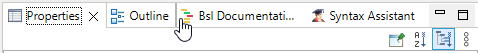
-
Release the left mouse button.
Detaching Panels and Editors
Detached panels and editors are displayed in an individual window. They function just like other panels and editors located within the main window. If you're using two screens, it may be convenient to detach certain panels or editors and place them on the second screen. To do this:
-
Click on the title of the panel or editor you want to detach.
-
Drag it outside the main window.
-
You can drag a panel or editor into the window of another detached editor or panel to create a group of detached panels.
To place a detached panel or editor back into the main window, drag it back using its title.
You can also reset the entire perspective to its original view—more details are available in the section Restoring a Perspective.
Docking Editors
1C:EDT allows you to open different files in multiple editors. All these editors are displayed in separate tabs, overlapping each other.
You can arrange editor windows side by side within the editor area. To do this, drag an editor's title downward, to the right, or to the left. 1C:EDT will highlight the area where the editor window can be moved:
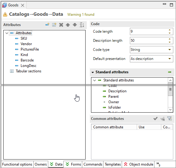
Release the left mouse button, and the windows will be arranged side by side:
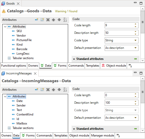
You can then adjust the size of the editor area or the divider position between the open windows by dragging it.
This operation is similar to moving panels within the main window, except that editor windows are confined to the editor area.
Maximizing and Minimizing Tools
The main 1C:EDT window is equipped with various tools. It typically contains the editor area (where a group of open editors is located) as well as one or more groups of panels surrounding the editor area. All these tools compete for screen space. Proper management of the available space for each tool can significantly enhance productivity in 1C:EDT.
There are two common operations to address this issue: minimization, which reduces the space used by a tool as much as possible, and maximization, which allocates as much space as possible to a tool. 1C:EDT offers several ways to perform these operations:
- Using the buttons
 (Minimize) and
  (Expand) located in the group panel's title bar
 - Double-clicking the group panel's title bar
- Using the keyboard shortcut Ctrl+M, which toggles the current active element between maximized and normal states

Maximization
Maximization is needed when you want to focus on a specific tool, excluding others. The editor area is, of course, the most common candidate for maximization. Maximizing the editor area provides the largest possible space for editing. However, there are workflows where it is beneficial to focus on a specific panel as well.
In 1C:EDT, maximization minimizes all other groups of panels (except the required one). This allows the required group to occupy all available space while keeping access to any open panels in your perspective.
Additionally, if the editor area contains multiple docked windows, the entire area is maximized together. This makes it comfortable to perform tasks that require simultaneous viewing of multiple files on the screen.
Minimization
Another operation to optimize screen space is minimizing those groups of panels that are not currently of interest. A minimized group of panels is displayed as a small panel located on the left or right side of the screen. This panel contains an individual icon for each collapsed panel and a general icon for restoring the entire group.

Clicking on the icon of a collapsed panel temporarily activates it, overlaying the current perspective content.

Once the focus shifts to another panel, the minimized panel automatically collapses again. Dragging the edges of the open window allows you to adjust the size of the panel that opens in this manner.
In minimized mode, the editor area appears slightly differently: it contains only one icon representing the entire editor area. In most cases, the editors are identical, so displaying individual icons for each editor window is unnecessary.
Recommendations
If your workflow requires having more than one tool on the screen simultaneously (for example, the editor area and a panel group), you can create additional space by minimizing the groups of panels that are not currently of interest. These groups will be collapsed to the left and right sides of the screen, allowing more space for other tools.
There are two ways to minimize a group of panels:
- Directly minimize the group itself
- Maximize another group, which will automatically minimize the remaining groups
The method used to achieve a minimized group determines its subsequent behavior. A group minimized by maximizing another important group will return to its normal state when the maximization of the important group is canceled. A group minimized directly will remain minimized.
This distinction is important because it allows precise control over the free space on the screen. While maximization is simple and run with a single click, it essentially implements an all-or-nothing approach. This means no other tool is allowed to share space with the maximized tool.
However, in most workflows, you are likely to want the main window to display more than one tool. In this case, do not maximize anything, but minimize all groups of panels except those you need. Once you configure this view, you can still maximize the editor area if needed, but when you cancel the maximization, only the required panel groups will be restored. The rest, directly minimized, will remain collapsed.
Enabling Dark Theme
1C:EDT includes several color themes that allow you to change the color scheme and fonts of all perspectives and panels with a single action. By default, 1C:EDT uses the Light theme.
In addition, there is a dark theme (Dark), which has been adapted for use within 1C:EDT. All elements used in 1C:EDT are displayed in a dark palette.
The only exceptions are interface objects that you need to see exactly as the user will see them: a spreadsheet document, a graphical schema, a form in the form editor’s preview window, or a layout for the data composition system.
Enabling the Dark Theme
- Click Window > Preferences... > General > Appearance > Theme: Dark.
- Click Apply and Close.
- Click Restart to avoid unwanted visual artifacts.
Reverting to the Default Theme
- Click Window > Preferences... > General > Appearance > Restore Defaults.
- Click Apply and Close.
- Click Restart.
After enabling the dark theme, you can customize colors used in it. Similarly, you can customize the colors of the light theme if it is enabled.
To learn how to enable the dark theme in the 1C:EDT Start launch and update application, read here.
Changing Keyboard Shortcuts
1C:EDT provides extensive options for customizing keyboard shortcuts.
Customization is done in the Keys section of the preferences. To open this section, click Window > Preferences... > General > Keys.
Changing Font and Color
You can change the font or color used in 1C:EDT. The colors available for customization depend on the currently selected theme light or dark.
To change colors and fonts:
-
Click Window > Preferences... > General > Appearance > Colors and Fonts.
-
Select the font or color you want to modify. The colors used in 1C:EDT are grouped under names starting with "1C ...":
-
1C Core Colors
-
1C Compare/Merge
-
1C Tables with Column Grouping
-
-
Press Edit.
-
Use the dialog that appears to select a font or color.
-
Press OK.
Managing Single and Double Click Actions
You can configure how 1C:EDT responds to single and double mouse clicks. To do this:
-
Click Window > Preferences... > General.
-
In the Open Mode group, select the desired behavior (Double Click or Single Click).
-
Click Apply and Close.
Note that changing this parameter may not affect all panels.
If you select the Single Click option, two additional checkboxes become available for more precise configuration.
-
Select on Hover means that to select a resource, you only need to hover over it with the mouse pointer.
-
Open on Arrow Key Press means that you can open a resource by moving to it using the Up or Down arrow keys.
Transferring 1C:EDT Preferences to Other Workspaces
The 1C:EDT preferences you configure in one workspace, such as keyboard shortcuts and the color scheme of the 1C:Enterprise Language Editor, can be used in other workspaces. You can also share settings with other developers.
The ability to export and import 1C:EDT preferences files makes it easy to share personal and team configurations.
Exporting
-
Click File > Export... > General > Preferences.
-
Check Export All to include all preferences in the file.
-
If you want to export only specific preferences, select them from the list.
-
Click Browse... and specify the directory and file name for saving the preferences file.
-
Click Finish.
Note: If you have not modified the default 1C:EDT preferences, the preferences file will be empty.
Importing
-
Click File > Import... > General > Preferences.
-
Click Browse... and specify the location of the preferences file.
-
Check Import All to import all preferences contained in the file.
-
If you want to import only specific preferences, select them from the list.
-
Click Finish.
1C:Enterprise Platform
System of 1C:Enterprise Applications
1C:Enterprise is a system of applications that includes a platform and a set of configurations built on it, designed for various industries and enterprises of different scales.
The platform is a mass-distributed product that provides technologies necessary for running configurations, as well as tools for developing and modifying them.
Platform
- Serves as the foundation for building configurations
- Includes the tools necessary for configuration administration and maintenance
- Acts as the runtime environment for configurations
- Uses a multi-tier architecture for running configurations: client application, 1C:Enterprise server cluster, database server
- The client part of the platform includes several client applications (thin client, web client, thick client). These applications are launched by users.
- The server part of the platform includes a server cluster, which ensures multi-user data operations. Client applications interact with the server cluster.
- There are two versions of 1C:Enterprise: desktop version and mobile version
- The desktop version is designed for creating and running configurations on computers with Windows, Linux, or macOS operating systems.
- The mobile version is intended for debugging and building mobile applications that will run on mobile devices with Android, iOS, or Windows operating systems.
Configuration
- Functions as an independent entity and can serve as a standalone application
- Fully relies on platform technologies
- The foundation of a configuration is described declaratively as a set of configuration objects created based on platform prototypes
- The behavior of a configuration is defined using algorithms written in the 1C:Enterprise language
- A single configuration without modifications can use different database management systems for data storage. This capability is provided by the platform.
- A single configuration without modifications can also run in different desktop client applications, provided that development standards are followed.
- A desktop configuration can also run in the mobile version of 1C:Enterprise, but certain modifications are required:
- For running in the mobile client platform, minimal changes are needed.
- For running in the mobile client platform with offline mode, medium-level modifications are necessary.
- For running in the mobile platform, significant modifications are required.
The platform runs the configuration. To run a configuration, infobases are always used since they contain both the configuration and user data. An infobase is essentially an instance of an application.
A user can create an unlimited number of infobases (instances of the application) from a single configuration. Each of these infobases (instances) will have the same configuration but different data.
For example, one infobase might be used for accounting (with real data), another for exploring the application solution (with demo data), and a third for training purposes (with arbitrary data).
1C:EDT and the 1C:Enterprise Platform
1C:EDT stores configurations as custom format files on disk.
In theory, this allows you to develop without an infobase or even without having the 1C:Enterprise platform installed on your computer.
Of course, both the platform and infobases are necessary. However, the starting point for development is the configuration itself. Which infobase to run it in and which platform version to use is entirely up to you and depends on your needs.
The important thing is that when you switch to another infobase (with different data) for debugging or choose a different platform version for running the configuration, you remain within the development context.
Desktop Version of 1C:Enterprise
The desktop version of the 1C:Enterprise platform is designed for creating configurations and running applications on computers with Windows, Linux, or macOS operating systems.
It is used by developers, administrators, and users.
There is only one variant of the desktop version, unlike the mobile version of 1C:Enterprise. It provides full functionality for interacting with infobases.
The application is used as follows. A user has the platform, developed by 1C, and a configuration created by a developer. The user runs one of the platform's client applications, such as the thin client, which runs the configuration.
The user independently selects the client application they will use. Desktop client applications can launch configurations created by any developer.
There are multiple installation packages of the desktop version, unlike the mobile version of 1C:Enterprise. Some installation packages are available for different operating systems, including Windows, Linux, and macOS. Other installation packages include only the server component and are intended for installation on servers where direct user interaction is not required.
Additionally, each operating system has a separate installation package of one of the client applications, the thin client. This is a lightweight installation package designed for users who do not need to develop or administer application solutions. It allows them to access and use existing infobases without additional configuration.
Note: To read about installing the desktop version of the platform for use with 1C:EDT, click here.
Platform Versions Parameter Group
The Platform Versions parameter group displays the versions of 1C:Enterprise available to 1C:EDT.
When launched, 1C:EDT automatically detects and adds to this list all versions of the desktop platform installed on the computer using the 1C:Enterprise installation program.
Desktop platform versions added via copying, as well as mobile platform versions, must be added to this list manually.
Open the Platform Versions parameter group
Click Window > Preferences... > V8 > 1C:Enterprise > Platform Versions.
Update platform versions
If new versions of 1C:Enterprise were installed using the installation program after launching 1C:EDT, the platform version list can be updated without restarting 1C:EDT.
- Open the Platform Versions parameter group.
- Click Update.
- Click Apply and Close.
Add Platform Version
If a new platform version was added by copying after launching 1C:EDT, it can be added to the list of versions without restarting 1C:EDT.
- Open the Platform Versions parameter group.
- Click Add.
- In the Location field, enter the path to the platform version directory. To select it interactively, click Directory....
- 1C:EDT will display the version, name, and contents of the selected platform version.
- Click Apply and Close.
Assigning a Specific Version to a Mask
To simplify development and debugging, 1C:EDT uses platform version masks for 1C:Enterprise. For example, a mask could be <8.3.22> or <8.3>.
When selecting one of these masks for a new project, 1C:EDT will use the latest available platform version that matches the mask.
However, this is not always convenient. For example, when interacting with server-based infobases. it may be necessary to assign a specific version to a mask. To do this:
-
Click Window > Preferences... > V8 > 1C:Enterprise.
-
In the Platform Versions window, select the required template on the left.
-
In the Platform Versions window on the right, check the box for the version that should be used for this template.
-
Click Apply and Close.
Performance Monitoring and Statistics Collection
1C:EDT includes a performance monitoring and statistics collection mechanism. This mechanism tracks the performance of 1C:EDT, automatically collects statistics on encountered errors, and logs data on the usage of various features within 1C:EDT.
By default, this mechanism is enabled after 1C:EDT is installed, and the collected statistics are automatically aggregated and sent to the monitoring service for analysis. The monitoring service is hosted within the infrastructure of 1C.
Statistics collection helps analyze how 1C:EDT operates, make informed decisions about its future development, and evaluate changes in performance across different operations depending on the application version, computer specifications, Java version, and other parameters.
The collected data includes:
-
Execution time of various operations in 1C:EDT that are relevant for analysis.
-
Usage statistics for different 1C:EDT features.
-
Encountered errors.
-
Computer specifications, operating system details, and Java version.
All this information is anonymized and does not contain personal user data.
The set of monitored operations in 1C:EDT may change from version to version. Currently, data is collected for only a few types of operations:
-
Opening all editors.
-
Generating content for editor pages.
-
Generating contextual help content for the 1C:Enterprise Language Editor.
Disabling the Mechanism
If desired, you can disable the collection and transmission of statistics in the 1C:EDT preferences (below) or in the settings of the launch and update application.
Statistics Collection Parameter Group
The Statistics Collection parameter group allows you to disable the performance monitoring and statistics collection mechanism.
You can access this parameter group by clicking Window > Preferences... > V8 > Statistics Collection.
Chapter 4. Projects
Since 1C:EDT is based on Eclipse technologies, it follows the same development ideology. The unit of development is the project, which is essentially an application. A project can be run and debugged. This means that each configuration is an individual project.
However, the specifics of 1C:Enterprise introduce additional characteristics, resulting in three distinct types of projects that can be used during development:
-
Configuration Project: Contains a single configuration.
-
Configuration Extension Project: Contains a single configuration extension.
-
External Reports and Data Processors Project: Contains multiple external reports and data processors.
Typically, a single workspace includes:
-
One configuration project: The main application being developed.
-
One or more extension configuration projects (if needed): Extensions intended to interact with the application.
-
One external reports and data processors project (if needed): Reports and data processors that can be used with the application during development.
1C:Enterprise Perspective
The 1C:Enterprise Perspective is the main workspace for application development. It includes all the tools required for creating and modifying configurations, editing forms, modules, query texts, and more.

This perspective opens automatically when 1C:EDT is launched. You can also open this perspective manually.
Open the 1C:Enterprise Perspective
You can open the 1C:Enterprise Perspective in several ways:
- From the Perspectives Panel: click (Open Perspective), then 1C:Enterprise
- From the main menu of the main window, click Window > Perspective > Open Perspective > Other... > 1C:Enterprise
The standard composition of the 1C:Enterprise Perspective includes the following elements:
-
Navigator Panel. This panel displays a list of applications and their elements being developed in 1C:EDT: configuration projects, extension configuration projects, and external reports and data processors projects.
-
Editor Area. This area can automatically open the Configuration Object Editor, Form Editor, 1C:Enterprise Language Editor, and other editors.
-
Panels:
-
Properties. This panel displays the properties of the item selected in the Navigator panel or in the form editor, such as a configuration object, attribute, form item, and so on.
-
ER Diagram. This panel displays a grouped list of procedures, functions, and events for the module open in the 1C:Enterprise Language Editor.
-
Syntax Assistant. This panel provides real-time suggestions for types, events, methods, and properties of the 1C:Enterprise language.
-
Bsl Documenting Comment. This panel is provided by the plugin 1C:Code Style V8. It displays the structure of documenting comments, allowing you to correct errors during their creation.
-
-
Panels on the Right Side of the Screen (Collapsed):
-
Configuration Errors. This panel shows errors and warnings detected during automatic configuration validation.
-
Infobases. This panel displays a list of infobases registered on your computer.
-
When analyzing a module or its ER diagram in the 1C:Enterprise perspective, the Call Hierarchy panel may open automatically. When analyzing module calls, the Search panel may open.
Navigator Panel
The Navigator panel displays a list of applied solutions and their elements developed using 1C:EDT, including configuration projects, extension configuration projects, as well as external reports and data processor projects.
This panel is part of the default perspectives 1C:Enterprise, Debugging, and Data ER Diagram.
Open the Navigator Panel
Click Window > Show View > Other… > 1C:Enterprise > Navigator.
This panel is populated with data as you create new projects, import configurations from infobases, or import projects from Git repositories.
Information Structure
The list of applications and their elements has a hierarchical structure. At the first level of the hierarchy are 1C:Enterprise projects: configuration projects, extension configuration projects, and external reports and data processor projects. Each such project contains a configuration object tree.
Configuration projects and extension configuration projects contain a complete tree, including all branches of objects available for development. External reports and data processor projects contain a truncated tree with only two branches: Data Processors and Reports.
All operations with projects, configuration trees, and individual configuration objects are run using the context menu.
Legend
-
 ,
,  ,
,  : Icons of Configuration Objects. Each class of configuration objects has its own icon. You can understand what objects a particular icon represents by looking at the parent group of those objects.
 :
:  :
:  :
:  :
:  :
: Configuration with Vendor Support Enabled
If a configuration is supported by the vendor, see 1C:Enterprise Documentation, 1C:EDT displays the support rule in the upper-left corner of the icon:
 The object is not editable.
 The object is editable while retaining support.
 The object is no longer supported.
Configuration Validation Results
If a configuration validation detects an error in any of its elements, 1C:EDT displays the error severity in the lower-left corner of the icon:
 Blocker.
 Critical.
 Major.
 Minor.
 Trivial.
The parent element also reflects the severity of its descendant’s error. If the descendants have errors with different severities, the parent element will show the highest severity.
In addition to these designations, icons from older configuration checks not yet migrated to the new mechanism may appear:
 The element has an error.
 The element has a warning.
Project Association with the Infobase
If a configuration project has an Automatically Updated Infobase, 1C:EDT displays its name in angle brackets after the project name.
 The project is associated with the UPDemo infobase.
Association with a Git Repository
If a project is under version control, the name of the repository and the current branch are displayed in square brackets after the project and infobase names in 1C:EDT.
 The project is versioned in the repository EDTRepository, current branch: master.
If a remote repository is used in addition to a local one, 1C:EDT can show the differences after the branch name, for example the number of commits not pushed to the remote repository or not merged with the local branch:
 The local branch has two commits not pushed to the remote repository.
 The local branch has one commit not pushed to the remote repository, and the remote repository has one commit not merged with the local branch.
State of Objects in the Git Repository
The state of resources under version control is indicated by an icon in the lower right corner of the resource's icon:
 This represents an object, file, that is not yet under version control.
 This represents a new object, file, that has been added to the index and is ready for commit to the repository.
 This represents an object, file, that is already under version control. It remains unchanged since the last commit.
 This represents a modified object, file, that is already under version control but is not yet added to the index.
 This represents an object, file, that was under version control but has been deleted.
 This represents a file with unresolved merge conflicts.
 This represents a file that is ignored by the Git version control system.
 This represents a file marked as Assume Unchanged.
Configure Git Resource Indicators
Click Window > Preferences... > Version Control (Team) > Git > Label Decorations in the main menu. Learn more in the section with the same name.
Command Bar
-
 (Back) appears after executing the command Enter. Returns to the previous panel view before executing the last command Enter.
 -
 (Forward) appears after executing the command Enter. Moves to the next panel view obtained as a result of executing the command Enter.
 -
 (Up) appears after executing the command Enter. Displays the parent element of the current view in the panel (either the project or the entire workspace).
 -
 (Collapse All) Collapses all hierarchy levels in the panel down to the first level.
 -
 (Link with Editor) Links the panel with the editor so they function synchronously. The panel automatically highlights the element being edited.
 -
 (By Subsystems) opens a dialog that allows displaying only those configuration objects belonging to specific subsystems in the panel. If such a filter is already applied, the same dialog allows modifying or removing it entirely (see 1C:Enterprise documentation).
 -
(Show Menu) Opens a drop-down menu containing additional commands for the panel.
-
Top-Level Items: Not used in the development of 1C:Enterprise applications.
-
Select Working Set...: Not used in the development of 1C:Enterprise applications.
-
Deselect Working Set...: Not used in the development of 1C:Enterprise applications.
-
Change Active Working Set...: Not used in the development of 1C:Enterprise applications.
-
Working Set Window: Not used in the development of 1C:Enterprise applications.
-
Filters and Settings...: opens a dialog that allows you to display standard attributes of objects in the configuration tree. To do this, uncheck the filter Standard Attributes and Tabular Sections..
-
Link with Editor: Links the panel with the editor so they function synchronously. The panel automatically highlights the element being edited..
-
Project Context Menu
-
New: The submenu contains commands for creating new projects and configuration objects.
-
Enter: Changes the panel view to display only the selected project or group of configuration objects.
-
Show In: The submenu contains the following commands:
-
Explorer: Opens the system file explorer to the directory containing the project files.
-
Properties: Displays the properties of the configuration contained in the project in the Properties panel.
-
-
Enable Strict Typing (@strict-types) in Modules in modules belonging to the selected configuration branches, enables strict typing by adding the annotation //@strict-types at the beginning of the modules.
-
Delete: Deletes the project.
-
Copy copies the selected element to the clipboard.
-
Paste: Pastes from the clipboard.
-
Update Configuration... Exports the configuration from the project to the infobase (about selecting the platform version) and then updates the database configuration.
-
Show Infobase
: Highlights the associated infobase in the Infobases panel. -
Publish Infobase... Publishes the infobase on the web server.
-
Publish Mobile Application... Publishes the mobile application on the web server.
-
Open Project Editor: Opens the Configuration Project Editor, Extension Configuration Project Editor, or External Report and data processor Project Editor.
-
Format all 1C:Enterprise Language Modules: Formats all modules according to the formatting settings.
-
Import...: Opens the import wizard selection dialog. Import wizards specific to 1C:Enterprise are located in the 1C:Enterprise group.
-
Export...: Opens the export wizard selection dialog. Export wizards specific to 1C:Enterprise are located in the 1C:Enterprise group.
-
Refresh: Updates the project tree.
-
Close Project: Closes the project.
-
Close Unlinked Projects: Closes projects not linked to this one. Projects can be linked to extension projects and external report and data processor projects. This is managed using their property Base Project.
-
Run As Launches the application contained in the selected project (about selecting the platform version). The submenu contains commands for quickly launching a specific client application.
-
1C:Enterprise Web Client Launches the web client.
-
1C:Enterprise Mobile Client on Android OS Launches the mobile client.
-
1C:Enterprise Thick Client Launches the thick client.
-
1C:Enterprise Thin Client Launches the thin client.
-
Launch Configurations... Opens the Launch Configuration Editor. The Debug Connection tab will be unavailable (learn more).
-
-
Debug As Launches the application in debug mode (about selecting the platform version). The submenu contains commands for quickly launching a specific client application in debug mode.
-
1C:Enterprise Web Client Launches the web client in debug mode.
-
1C:Enterprise Mobile Client on Android OS Launches the mobile client in debug mode.
-
Connect to 1C:Enterprise Debug Server Launches the debug server connection configuration.
-
1C:Enterprise Thick Client Launches the thick client in debug mode.
-
1C:Enterprise Thin Client Launches the thin client in debug mode.
-
Debug Configurations... Opens the Launch Configuration Editor.
-
-
Profile As: Not used in the development of 1C:Enterprise applications.
-
Restore from Local History... Restores deleted configuration objects from local history.
-
Compare/Merge opens a dialog for comparing and merging two projects.
-
Version Control (Team) submenu contains the following commands.
-
Shared Project... appears when the project is not under version control. Opens a dialog for configuring a Git repository where this project will be versioned.
-
Commit... opens the Git Staging panel for committing project changes to the local repository.
-
Stashes submenu contains the following commands.
-
Push to origin sends changes to the remote repository named "origin".
-
Fetch from Origin retrieves changes from the remote repository named "origin".
-
Push Branch 'branch-name'... sends the selected branch to the remote repository. You can choose a repository or create a new one, select the branch to push, and configure push and fetch settings for the remote repository.
-
Pull fetches changes from the upstream repository and merges them into the current branch.
-
Pull... fetches changes from the selected remote repository and merges them into the current branch.
-
Create New Branch... creates a new branch using 1C:EDT (links it to a new or existing infobase).
-
Switch To switches the project to a different branch. The submenu provides options to choose from local branches in the current repository. It also includes options to create a new branch or select from other repository elements such as tags and remote tracking branches.
-
Delete Branch... deletes a Git branch and, optionally, its linked infobase. The current branch, to which the project is switched, cannot be deleted.
-
Remote Repository submenu contains the following commands.
-
Push... sends changes to the selected remote repository.
-
Push Tags... sends the selected tags to the remote repository.
-
Fetch From... retrieves changes from the selected repository that are missing in the local object infobase.
-
Configure Push to Upstream... allows configuring push settings to the upstream repository.
-
Configure Fetch from Upstream... allows configuring fetch settings from the upstream repository.
-
-
Advanced Options: The submenu contains the following commands.
-
Rename Branch... renames the branch.
-
Delete Branch... deletes the branch using standard Git tools.
-
Synchronize Not used in 1C:Enterprise application development. Synchronizes the working tree with the selected branch of the chosen repository. This is done using the Synchronize perspective. The submenu contains additional commands besides local repository branches.
- Custom... opens a dialog for selecting a repository.
-
Create Tag... creates a tag.
-
Clean... removes files and folders from the working tree that are not under version control.
-
Assume Unchanged marks a file as Assume Unchanged.
-
No Assume Unchanged removes the Assume Unchanged mark from the file.
-
Remove from Version Control removes the object from Git version control but leaves it in the working tree.
-
Synchronize Workspace synchronizes the working tree with the remote repository. This is done using the Synchronize perspective.
-
Merge Tool resolves merge conflicts using the standard merge tool.
-
Reset... reverts the changes made in the working tree.
-
Soft (HEAD Only) The HEAD pointer will be set to this commit, while the index and working tree remain unchanged.
-
Mixed (HEAD and Index) The HEAD pointer will be set to this commit. The index will match this commit, but the working tree will remain unchanged.
-
Hard (HEAD, Index, and working tree) The HEAD pointer will be set to this commit. The index and working tree will match this commit.
-
-
Create Patch... creates a patch.
-
Apply Patch applies a patch.
-
Ignore adds the file to .gitignore so that Git ignores it (learn more).
-
Show in Git Repositories Panel opens the project in the Git Repositories panel.
-
Disconnect disconnects all Git Team providers from this project. The Git repository continues to exist, but 1C:EDT no longer interacts with it.
-
-
Merge... merges the selected branch into the current branch.
-
Rebase... moves the changes from the current branch to the selected branch.
-
Add to Index adds all files from the Unstaged Changes section to the index.
-
Remove from Index removes all files from the index.
-
Show History opens the History panel and displays resources from the current repository.
-
-
Compare submenu contains the following commands:
-
Compare with Each Other Not used in 1C:Enterprise application development. Compares projects with each other.
-
HEAD Revision compares this resource in the working tree with the last commit.
-
Index compares this resource in the working tree and in the index.
-
Previous Revision compares this resource with the previous commit.
-
Branch, Tag, or Reference... compares the working tree with the selected branch, tag, or reference.
-
Commit... compares the working tree with the selected commit.
-
-
Replace With submenu contains the following commands.
-
HEAD Revision replaces the working tree with the last commit.
-
Index replaces the working tree with the index.
-
Previous Revision replaces the working tree with the previous revision.
-
Branch, Tag, or Reference... replaces the working tree with the selected branch, tag, or reference.
-
Commit... replaces the working tree with the selected commit.
-
-
Run Validation runs the configuration validations. This command appears if specified in the validation settings.
-
Properties opens 1C:EDT preferences related to projects.
Configuration Context Menu
-
All Event Subscriptions opens the editor All Event Subscriptions.
-
All Roles opens the editor All Roles.
-
Open Application Module opens the application module in the 1C:Enterprise Language Editor.
-
Open Session Module opens the session module in the 1C:Enterprise Language Editor.
-
Open External Connection Module opens the external connection module in the 1C:Enterprise Language Editor.
-
Open Start Page Workspace opens the start page workspace editor.
-
Open Command Interface opens the command interface editor.
-
Open Client Application Interface opens the client application interface editor.
-
Open opens the configuration properties in the configuration editor.
-
Reference Information opens configuration reference information in the HTML Editor.
-
Open With submenu contains commands for opening the file describing the selected configuration tree element using different editors.
-
Enable Strict Typing (@strict-types) in Modules in modules belonging to the selected configuration branches, enables strict typing by adding the annotation //@strict-types at the beginning of the modules.
-
Delete: Not used in the development of 1C:Enterprise applications.
-
Properties opens configuration properties in the Properties panel.
-
Copy: Not used in the development of 1C:Enterprise applications.
-
Paste: Not used in the development of 1C:Enterprise applications.
-
References submenu contains the following commands:
- Find References to Object finds configuration objects that reference the selected object.
-
Compare/Merge opens a dialog for comparing and merging two configuration objects.
-
Version Control (Team) submenu contains the following commands.
-
Commit... opens the Git Staging panel for committing project changes to the local repository.
-
Advanced Options: The submenu contains the following commands.
-
Assume Unchanged marks a file as Assume Unchanged.
-
No Assume Unchanged removes the Assume Unchanged mark from the file.
-
Remove from Version Control removes the object from Git version control but leaves it in the working tree.
-
Synchronize Workspace synchronizes the working tree with the remote repository. This is done using the Synchronize perspective.
-
Create Patch... creates a patch.
-
Ignore adds the file to .gitignore so that Git ignores it (learn more).
-
Show in Git Repositories Panel opens the project in the Git Repositories panel.
-
Disconnect disconnects all Git Team providers from this project. The Git repository continues to exist, but 1C:EDT no longer interacts with it.
-
-
Show History opens the History panel and displays resources from the current repository.
-
-
Compare submenu contains the following commands:
-
HEAD Revision compares this resource in the working tree with the last commit.
-
Index compares this resource in the working tree and in the index.
-
Previous Revision compares this resource with the previous commit.
-
Branch, Tag, or Reference... compares the working tree with the selected branch, tag, or reference.
-
Commit... compares the working tree with the selected commit.
-
-
Replace With submenu contains the following commands.
-
HEAD Revision replaces the working tree with the last commit.
-
Index replaces the working tree with the index.
-
Previous Revision replaces the working tree with the previous revision.
-
Branch, Tag, or Reference... replaces the working tree with the selected branch, tag, or reference.
-
Commit... replaces the working tree with the selected commit.
-
-
Run Validation runs the configuration validations. This command appears if specified in the validation settings.
Context Menu of an Applied Configuration Object
-
Create submenu contains commands for creating new configuration objects and their components.
-
Find Event Subscriptions submenu contains all or some of the listed commands:
-
Object opens the editor All Event Subscriptions and displays subscriptions to object module events for the selected configuration object.
-
Manager opens the editor All Event Subscriptions and displays subscriptions to manager module events for the selected configuration object.
-
Record Set opens the editor All Event Subscriptions and displays subscriptions to record set module events for the selected configuration object.
-
All opens the editor All Event Subscriptions and displays all subscriptions to non-interactive events related to the selected configuration object.
-
-
Wizards submenu contains the following commands:
-
Print Wizard... opens the print wizard for the selected configuration object.
-
Create Based-On Wizard opens the input wizard based on the selected document.
-
Record Wizard... opens the record wizard for the selected document.
-
-
Open Command Module opens the command module in the 1C:Enterprise Language Editor.
-
Open Manager Module opens the manager module in the 1C:Enterprise Language Editor.
-
Open Value Manager Module opens the value manager module in the 1C:Enterprise Language Editor.
-
Open Record Set Module opens the record set module in the 1C:Enterprise Language Editor.
-
Open Object Module opens the object module in the 1C:Enterprise Language Editor.
-
Open Form Module opens the form module in the 1C:Enterprise Language Editor.
-
Add to Extension inherits the selected configuration object into the extension.
-
Open opens the main properties of the configuration object in the object editor.
-
Reference Information opens configuration reference information in the HTML Editor.
-
Open Default Object Form opens the form designated as the main form of this configuration object.
-
Open Default Group Form opens the form designated as the main form of the group of this configuration object.
-
Open Default Record Form opens the form designated as the main form of the record of this configuration object.
-
Open Default List Form opens the form designated as the main form of the list of this configuration object.
-
Open Default Choice Form opens the form designated as the main selection form of this configuration object.
-
Open Default Group Choice Form opens the form designated as the main selection form of the group of this configuration object.
-
Open With: Opens the configuration object description file in different editors.
-
Standard Attributes opens the standard attributes of the configuration object in the object editor.
-
Predefined Data opens predefined data of the configuration object in the object editor.
-
Characteristics opens the characteristics of the configuration object in the object editor.
-
Enable Strict Typing (@strict-types) in Modules in modules belonging to the selected configuration branches, enables strict typing by adding the annotation //@strict-types at the beginning of the modules.
-
Delete deletes the configuration object.
-
Move to Top moves the configuration object to the top of the list within its current hierarchy in the configuration tree.
-
Move Up moves the configuration object one position up within its current hierarchy in the configuration tree.
-
Move Below moves the configuration object one position down within its current hierarchy in the configuration tree.
-
Move Down moves the configuration object to the bottom of the list within its current hierarchy in the configuration tree.
-
Sort sorts configuration objects at the same level as the current object in ascending order by name.
-
Properties opens configuration object properties in the Properties panel.
-
Copy copies the selected element to the clipboard.
-
Paste pastes from the clipboard.
-
References submenu contains the following commands:
- Find References to Object finds configuration objects that reference the selected object.
-
Compare/Merge opens a dialog for comparing and merging two configuration objects.
-
Version Control (Team) submenu contains the following commands.
-
Commit... opens the Git Staging panel for committing project changes to the local repository.
-
Advanced Options: The submenu contains the following commands.
-
Assume Unchanged marks a file as Assume Unchanged.
-
No Assume Unchanged removes the Assume Unchanged mark from the file.
-
Remove from Version Control removes the object from Git version control but leaves it in the working tree.
-
Synchronize Workspace synchronizes the working tree with the remote repository. This is done using the Synchronize perspective.
-
Create Patch... creates a patch.
-
Ignore adds the file to .gitignore so that Git ignores it (learn more).
-
Show in Git Repositories Panel opens the project in the Git Repositories panel.
-
Disconnect disconnects all Git Team providers from this project. The Git repository continues to exist, but 1C:EDT no longer interacts with it.
-
-
Show History opens the History panel and displays resources from the current repository.
-
-
Compare submenu contains the following commands:
-
HEAD Revision compares this resource in the working tree with the last commit.
-
Index compares this resource in the working tree and in the index.
-
Previous Revision compares this resource with the previous commit.
-
Branch, Tag, or Reference... compares the working tree with the selected branch, tag, or reference.
-
Commit... compares the working tree with the selected commit.
-
-
Replace With submenu contains the following commands.
-
HEAD Revision replaces the working tree with the last commit.
-
Index replaces the working tree with the index.
-
Previous Revision replaces the working tree with the previous revision.
-
Branch, Tag, or Reference... replaces the working tree with the selected branch, tag, or reference.
-
Commit... replaces the working tree with the selected commit.
-
-
Run Validation runs the configuration validations. This command appears if specified in the validation settings.
Properties Panel
The Properties panel primarily shows the properties of the item selected in the Navigator panel or the configuration object editor.
Additionally, it can display the main properties of infobases and publications highlighted in the Infobases and Web Servers panels.
This panel is included in the standard perspectives 1C:Enterprise and Git.
Open the Properties Panel
Click Window > Show View > Other… > General > Properties.
Information Structure
Properties are grouped into categories by default. All categories are open,
and they, along with properties within them, are arranged by importance and frequency of use. The most important and frequently used properties appear at the top.
You can hide unnecessary property categories. You can sort properties alphabetically without grouping them into categories.
Find a Property in the List
To find a property in a large list, use the search field at the top of the panel. Start typing a fragment of the property's name, and 1C:EDT will automatically filter the list to show matching properties.
1C:EDT searches substrings located anywhere in the word. Special characters are not used.
To restore the full list of properties, click ![]() on the right side of the field.
on the right side of the field.
To avoid retyping the same search queries over and over, you can select one of the previously used entries. Click ![]() and choose the appropriate entry.
and choose the appropriate entry.
Hide Properties from Unnecessary Categories
For instance, when designing a form and positioning fields, you may only need properties from the Location category,
which is located near the bottom of the list. Switching between fields causes the list to scroll to the top, requiring you to scroll down repeatedly.
In this case, you can collapse unnecessary categories like General, Usage, and Appearance, which are located above Location. As a result, the properties from the Location category will always remain visible.
Hide Properties
Click ![]() to the left of the category name.
to the left of the category name.
Show Properties
Click ![]() to the left of the category name.
to the left of the category name.
Sort Alphabetically
Sort Alphabetically
To sort properties alphabetically without categories, click ![]() (Sort Alphabetically).
(Sort Alphabetically).
Show by Categories
To return to the default data representation in the panel, click ![]() (Display by Categories).
(Display by Categories).
Configuration Project
The configuration project contains a single configuration.
-
Infobase
-
.xml Files
-
Project Files
Automatic Update of Infobases
To run a configuration, 1C:EDT must transfer it to an infobase. After that, 1C:EDT launches a client application either in runtime mode or in debug mode.
Configurations developed in 1C:EDT can be quite large, and transferring the entire configuration to the infobase can take considerable time. To reduce the time needed for launching and debugging, 1C:EDT includes a mechanism to link projects to infobases.
Each project can be linked to one or more infobases. The configurations in these infobases are kept up to date by frequently transferring changes during the editing process.
As a result, when you launch a project on one of the linked infobases, it takes as much time as it would in Designer.
If you use the Git version control system, 1C:EDT provides an additional service that allows you to automatically use different infobases for different Git branches (details).
Methods for Automatic Update of Infobases
The recommended development scenario is to link one or more infobases to the project. This allows 1C:EDT to transfer configuration changes directly during the editing process. As a result, the time it takes to launch the configuration for debugging or execution in these infobases is nearly the same as in 1C:Enterprise Designer.
When importing a configuration from an infobase or creating a new configuration project, you can link the project to the infobase immediately. In this case, 1C:EDT uses the default link settings.
You can later edit these settings in the Applications panel.
1C:EDT supports two methods for updating the configuration in linked infobases:
Update Before Launch
This is the recommended update method.
In this mode, nothing is transferred to the infobase during editing. This is the main reason to choose this mode.
Otherwise, like updating during editing, it uses incremental configuration upload from XML files to transfer changes to the infobase. However, it does so only once, just before launch, or when you manually click Update Database Configuration in the Main Window Command Bar.
Since only configuration changes are transferred, it does not take much time. However, depending on the length of time since the last launch, the accumulated modifications may still cause a noticeable delay.
Update During Editing
In this mode, configuration changes are constantly and automatically transferred to the infobase directly during editing, for example each time you press Save in the 1C:Enterprise Language Editor or immediately after adding a new attribute to a configuration object.
When placing these changes into the infobase, the incremental configuration upload from XML files mechanism is used. Thus, only changes made to the configuration since its last export from 1C:EDT are loaded into the infobase. This process works as follows:
-
You modify the configuration in 1C:EDT. The modified objects are marked within 1C:EDT as needing to be loaded.
-
1C:EDT exports the modified objects from the 1C:EDT model to a temporary directory as configuration `.xml` files.
-
1C:EDT calls the batch mode of Designer and performs an incremental configuration upload from these files.
-
1C:EDT deletes the temporary directory.
-
If the upload is successful, 1C:EDT removes the objects from the list of those needing to be loaded. If unsuccessful, they remain on the list.
As a result, by the time you run the configuration, the infobase state will be the same as if you were editing it directly in 1C:Enterprise Designer. The infobase will contain the modified main configuration, fully matching the configuration in 1C:EDT. To launch it, the platform only needs to update the database configuration, carry out any necessary restructuring, and start the client application.
You could say that updating during editing ensures the highest level of readiness for the infobase to run.
Create a New Project for Configuration Development
You can create a new project in several ways:
-
In the Navigator panel, right-click the empty area, and select New > Configuration Project.
-
In the main menu, click File > New > Configuration Project.
1C:EDT automatically fills in all necessary fields in the wizard, allowing you to simply click Finish.
Field Descriptions
-
New Configuration:
-
Name is a string identifying the developed application among other 1C:Enterprise applications.
-
Alias is the application name displayed in the interface instead of the Name field.
-
Comment is a brief description of the application for the developer.
-
Project Name is a string identifying the project within 1C:EDT. The project name can differ from the configuration name if, for example, the configuration name is long, and you prefer shorter names in the Navigator panel.
Important: Be careful. Once a project is created, its name cannot be changed.
-
Default Location. By default, this checkbox is selected, and the project is placed in the directory that 1C:EDT automatically specifies in the Location field.
-
Location is the directory where the project will be located. To change it, clear the Default Location checkbox.
-
Version is the platform version mask for 1C:Enterprise to be used for this project.
The platform matching this mask will be used for automatic configuration validation, interaction with automatically updated infobases, and application launch by default.
By default, 1C:EDT selects the highest version of the platform installed on the computer that matches this mask. If you do not want to use the highest matching version, you can specify a particular platform version to be used when selecting this mask. To learn more, see Assigning a Specific Version to a Mask.
Important: Be careful. Once a project is created, the version mask cannot be changed.
-
-
1C:Development Standards V8. Project Settings:
This page allows you to configure the 1C:Code Style V8 plugin settings. The plugin helps develop configurations in accordance with the standards and guidelines of the 1C:Enterprise platform. The settings purpose is described in the interface.
-
Create a New Application When creating a project, you can immediately create an application to be used for debugging and launching the project:
-
Application on a File-Based, Client-Server, or Remote Infobase: the infobase will be connected directly to 1C:EDT for debugging and launching. In the next steps, you can select one of the existing infobases or create a new one.
-
Application on a Local Standalone 1C:Enterprise Server: a local file-based infobase connected to 1C:EDT through a standalone server will be used for debugging and launching. This option is preferable for large configurations. In the next steps, you can select one of the existing infobases or create a new one.
-
Migrate the Project to a New Platform Version
A new version of 1C:EDT may support a new version of the 1C:Enterprise platform. As a result, you may need to migrate the developed project to a new platform version.
When developing in a team, you can use one of two strategies for this migration:
Centralized Update in the Main Branch:
-
Merge all developers' local branches into the main branch on the server.
-
Migrate the main branch on the server to the new platform version.
-
Create new task branches from the updated state of the main branch.
Distributed Update:
-
Each developer merges the main branch from the server into their local branches, if necessary.
-
The project manager migrates the main branch on the server to the new platform version.
-
Each developer migrates their local branches to the new platform version.
-
Once the main branch on the server has been migrated, developers can merge their updated local branches into it.
Migrate to a New Version
To migrate a project located in a Git repository to a new platform version, follow these steps:
- Launch the old version of 1C:EDT.
- Commit all project changes, if any, to the Git repository (details).
- Upload the latest project state to the linked infobase (Update Configuration...), enabling the Load Full Configuration checkbox in the dialog.
- If the project directory contains your own files that are not generated by 1C:EDT, copy them to a temporary directory.
- Remember the project name and delete the project (Delete), enabling the Delete Project Content on Disk checkbox in the dialog.
- Close the old version of 1C:EDT.
- Make a backup copy of the infobase in case of failure.
- Migrate the infobase to the new platform version, following the recommendations (example).
- Launch the new version of 1C:EDT with the old workspace.
- Import the infobase into a new project with the same name as the old project.
- Add the project to the same Git repository.
- Copy your own files back into the project directory from the temporary directory created in step 4.
- Commit the project changes to the repository.
- In the project’s launch configurations, specify the new platform version.
Update the Project Based on the Infobase State
The infobase configuration may be modified outside 1C:EDT, for example, using Designer. In this case, 1C:EDT allows you to import these changes into an existing project. When performing this import, 1C:EDT compares and merges the project with the infobase configuration. If conflicting changes are detected, you must resolve the conflicts manually in the Compare and Merge Configurations Editor.
Updating a project based on the infobase state can be done in several cases:
During configuration import from the infobase. If the workspace already contains a project that automatically updates this infobase, 1C:EDT offers the option to either update the existing project or import the configuration into a new project.
When launching the project or during database configuration update, 1C:EDT may also suggest importing configuration changes from the infobase.
Update the Project Based on the Infobase State
You can update the project in several ways:
- Drag the infobase linked to the project from the Infobases panel to the Navigator panel.
- In the Infobases panel, click
 (Import Configuration...) in the command bar or infobase context menu.
 - In the Applications panel, select Import Configuration in the application context menu.
- In the Development panel, select Import Configuration in the infobase context menu, if the project is under Git version control.
1C:EDT will attempt to automatically determine the changes in the infobase configuration.
If successful, the changes list will appear in the wizard. Only these changes will be imported into the project, which should not take long.
If 1C:EDT cannot determine the infobase changes automatically, it will need to import the entire configuration, which may take considerable time.
At this point, you can choose between two options:
-
To cancel the configuration update in the project, click Cancel. The wizard will close, and 1C:EDT will take no further action.
-
To proceed with the update, click Import.
Once 1C:EDT imports the changes from the infobase, it opens the Compare and Merge Configurations Editor (details), allowing you to merge the project configuration with the infobase configuration.
Edit Project Properties
During development, you may need to view or modify certain project properties, such as checking the platform version or optimizing project data.
Open Project Properties
In the Navigator panel, right-click the project and select Open Project Editor.
Field Descriptions
- Platform Version. A version mask for the 1C:Enterprise platform.
The platform matching this mask will be used for automatic configuration validation, interaction with automatically updated infobases, and application launch by default.
By default, 1C:EDT selects the highest version of the platform installed on the computer that matches this mask. If you do not want to use the highest matching version, you can specify a particular platform version to be used when selecting this mask. To learn more, see Assigning a Specific Version to a Mask.
Important: Once a project is created, the version mask cannot be changed.
- Optimize Project Data Storage Format. Optimizes the internal format of the project’s
.xmlfiles.
Close Project
Closed projects are marked with an  icon.
icon.
When a project is closed, you cannot modify it in the main window, and its resources are not displayed in the Navigator panel. However, it remains on the file system. Closed projects require less memory. Closing projects that are not needed immediately, but may be required later, helps reduce, sometimes significantly, the launch time of 1C:EDT and the model building time for open projects.
Close Project
In the Navigator panel, right-click the project and select Close Project.
This operation is quick.
Open Project
In the Navigator panel, right-click the project and select Open Project.
This operation may take some time, as it involves the full sequence of model building performed during configuration import into 1C:EDT.
Import Configuration from an Infobase into a New Project
You can import a configuration from an infobase into a new project in several ways:
- Drag the infobase from the Infobases panel to the Navigator panel.
- In the Infobases panel, click (Import Configuration...) in the command bar or infobase context menu.
- In the Navigator panel, click Import... > 1C:Enterprise > Configuration from Infobase > Next in the context menu.
1C:EDT opens the import configuration wizard, where you can specify the project name and select the 1C:Enterprise platform version to be used for the application in this project.
Infobase Access Settings
If the imported infobase is used for the first time, 1C:EDT opens an infobase access settings dialog over the wizard.
In this dialog, you must select an infobase user with full rights. 1C:EDT will interact with the infobase on behalf of this user.
Platform Version
By default, 1C:EDT uses the latest installed platform version to create and modify projects.
If the infobase was created with another platform version, select the appropriate mask in the Project Version field.
If a specific platform version is required for import, not a mask, use this scenario.
If the required platform version is not installed on your computer, for example one used for a standalone server, complete the following steps:
- Without closing 1C:EDT or this dialog, install the 1C:Enterprise platform.
- Return to the dialog and click
 (Refresh Platform Version List) so that 1C:EDT detects the new platform version.
 - Select the new version template in the Project Version field.
Extensions
The imported infobase may contain configuration extensions. The wizard automatically detects them and offers to import them along with the main configuration.
You can decline this or select specific extensions for import.
Extensions are imported as individual projects linked to the main one. The configuration project will be set as the base project for all extension projects. The base project's name will be used as a prefix for the extension project names. Thus, all imported projects will be located next to each other.
Troubleshooting: If the infobase is open in Designer, import will be impossible.
If the infobase is already linked to a project, this command updates the configuration in the project with the one from the infobase.
During the import, 1C:EDT performs the following steps:
- Exports the configuration from the infobase to a temporary directory using a batch mode Designer command that exports the configuration to XML files.
- Loads these XML files into the workspace, converting them to 1C:EDT’s internal file format.
- Deletes the temporary directory.
- Builds the internal project model in 1C:EDT based on the internal file representation stored in the workspace. During this step, the following operations are performed:
- calculation of computed data
- calculation of search and other indexes
- model validation
- Creates an application for launching and debugging the project.
Import Configuration Using a Specific Platform Version
For various reasons, importing an infobase may require a specific version of the platform. The simplest case is a server-based infobase. Assume you have the following platform versions installed:
-
8.3.10.2753
-
8.3.10.2505
-
8.3.10.2466
Server components are only available in the "middle" version, 2505. In this case, proceed as follows:
-
Set a specific platform version for the mask <8.3.10>: 8.3.10.2505 (learn more).
-
Import the configuration from the infobase (learn more).
-
After importing, revert the mask <8.3.10> to its original state.
-
Specify platform version 8.3.10.2505 in the infobase access settings.
Import a Configuration Under Full Support
If the configuration in the infobase is under full support, you can import such a configuration into 1C:EDT, run it, and debug it in the same infobase.
However, you will not be able to modify such a configuration using 1C:EDT. If you want to change the support mode or completely remove support, this must be done before the import in 1C:Enterprise Designer.
Export Configuration to Another Infobase Accessed by Users
Once you have developed and debugged the configuration, you can export it directly to the production infobase used by end users. This means exporting it to an infobase that was not used for this project during its development.
There are several ways to export a configuration to an infobase:
-
Method 1:
-
Drag the project from the Navigator panel to the required infobase in the Infobases panel.
-
If you do not intend to use this infobase for further development of this project, uncheck the Start developing an application on this infobase option in the dialog box that appears.
-
-
Method 2:
-
In the Infobases panel, click
 (Update Configuration...) in the command bar or infobase context menu.
 -
Select the project from which you want to export the configuration.
-
If loading the configuration changes the infobase table structure, before updating the database configuration, 1C:EDT will display a dialog with the planned changes and ask for confirmation.
If the required platform version is not installed on your computer, for example one used for a standalone server, complete the following steps.
-
Without closing 1C:EDT or this dialog, install the 1C:Enterprise platform.
-
Return to the dialog and click
(Refresh Platform Version List) so that 1C:EDT detects the new platform version.
Export Configuration to a Linked Infobase
There are several ways to export a configuration to an infobase:
-
Drag the project from the Navigator panel to a linked infobase in the Infobases panel.
-
In the Navigator panel, click Update Configuration... in the context menu of the project.
-
In the Infobases panel, click
(Update Configuration...) in the command bar or the context menu of the infobase.
1C:EDT will load the configuration changes made after the last load into the infobase. This does not take much time.
If for any reason you doubt the correctness of incremental updates and want to be 100% sure that all changes made in the project are applied to the infobase, check the Load Full Configuration... option in the dialog. In this case, the entire configuration will be loaded into the infobase, but it may take considerable time.
If you invoke the configuration update from the Navigator panel, the dialog will display not just one infobase linked to the project but all applications linked to the project. This is convenient when the project is linked to several applications because you can immediately load the configuration into all the infobases of these applications or select only specific applications for loading.
Import Configuration from .xml Files
You can only import into a new configuration project in this way.
-
In 1C:Enterprise Designer, export the configuration to .xml files or an archive.
-
In 1C:EDT, in the Navigator panel, click Import... > 1C:Enterprise > Configuration from XML Files > Next in the context menu.
-
From a directory: choose this option if you exported the configuration to .xml files and specify the directory path.
-
From an archive: choose this option if you exported the configuration to an archive and specify the archive file path.
-
Project Name: enter the name of the future project.
-
Version: select the 1C:Enterprise platform version the future project will use. By default, 1C:EDT offers the platform version specified in the exported .xml files for the new project. However, you can select a newer version if you want to develop the application on a more recent platform.
-
-
Click Finish. A new project will be created, and the configuration will be imported into it.
Export Configuration to .xml Files
-
In 1C:EDT, in the Navigator panel, click Export... > 1C:Enterprise > Configuration to XML Files > Next in the context menu.
-
V8 Project: displays the project where the command was executed. If the command was executed in an empty area of the panel, select the project to be exported here.
-
To a directory: choose this option to export the project to a hierarchical structure of .xml files and specify the target directory.
-
To an archive: choose this option to package all exported files into an archive and specify the path to the archive file.
-
-
Click Finish. You can monitor the export progress in the export dialog. When the export is complete, 1C:EDT will display an informational message.
-
In 1C:Enterprise Designer, import the configuration from .xml files or an archive.
Import a Project from the File System or an Archive
To work with the contents of a Git repository, for example, you need to import its files and folders into the 1C:EDT workspace as projects.
If you clone a repository, the cloning wizard allows you to perform such an import immediately during the cloning process (check the box Import all projects after the cloning operation is complete).
However, you can import a project from the file system at any other time in several ways:
-
In the Git Repositories panel, click Import Projects... in the context menu of the repository or working tree.
-
In the Navigator panel, click Import... > General > Project from Folder or Archive in the context menu of the project.
Configuration Extension Project
Configuration Extension
Configuration Extension is very similar to a regular configuration. It is also represented as an object tree. The same methods used for regular configurations are applied to extensions.
Using extensions significantly simplifies adapting a standard application to the needs of a specific implementation or customer.
Often, customers want to add or modify something in the standard configuration to suit their requirements. The strategy offered by extensions ensures that modifying the standard configuration is unnecessary. All changes are made in the extension, which is essentially also a configuration.
Afterward, in the 1C:Enterprise mode, the extension is simply connected to the standard configuration. The platform automatically merges the extension with the standard configuration. As a result, the customer iteracts with a modified version of the standard solution tailored to their needs.
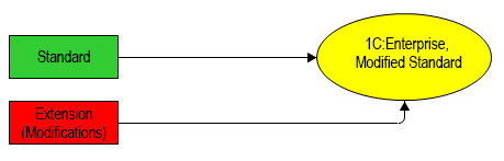
When the vendor releases a new version of the standard configuration, it is automatically updated because the support mode for the standard configuration remains unchanged. It stays under full support from the vendor. Upon launching the updated application, the platform will again automatically merge the updated standard configuration with the extension. The customer will continue to interact with the modified version of the standard solution.
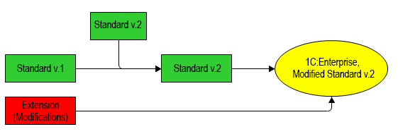
Extensions are indispensable when the application operates in data separation mode (see Data Separation Mechanism).
For example, in the service model (see 1C:Fresh Cloud Subsystem). One subscriber may need a couple of additional reports. Meanwhile, other subscribers prefer to interact with the original standard configuration.
For this specific subscriber, you can develop an extension implementing all their requests. The subscriber can connect this extension and use the modified configuration. Other subscribers will remain unaffected. because extensions are connected and executed based on the current values of the separators. It is also possible to apply extensions for all areas of a partitioned infobase.
Another situation involves customizing the standard configuration for a specific customer during implementation. Alternatively, modifications to the standard configuration may be run by the customer’s IT specialists independently. If all such customizations are implemented as extensions, the standard configuration will remain under full support, significantly simplifying its further maintenance.
For more information about extensions, see Configuration Extension.
Configuration Extension Project
An extension configuration project contains a single extension. It is recommended to associate this project with a configuration project (Base Project property). This association enables access to the configuration context when developing the extension and ensures that the extension is applied during configuration execution.
If you import a configuration from an infobase, you can simultaneously import all the extensions present in the infobase. This action will create a single project for the configuration and a separate project for each extension. The extension projects will immediately be associated with the configuration project.
However, you can import only one or several extensions from the infobase, link them to another configuration project, or develop them independently.
Create a New Project for Extension Development
To create a new project for extension development, in the panel Navigator click New > Configuration Extension Project in the context menu of an empty area.
1C:EDT automatically fills in all the required dialog fields, so you can simply click Finish. However, developers often specify a custom name for the extension to distinguish it among other 1C:Enterprise applications and provide its prefix.
Additionally, you can assign a project name different from the extension name. This option may be useful when the extension name is long, and you prefer using shorter names in the panel Navigator.
Important: Be careful. Once a project is created, its name cannot be changed.
You can also specify a base project immediately, which facilitates extension development and debugging. The base project is one of the projects in the workspace that contains the configuration for which an extension is created and with which it will be launched and debugged. The base project context will be available when developing the extension. If a base project is specified, the extension project name is automatically generated using the following principle:
If the base project is not specified initially, you can add it later in the extension configuration project editor.
Field Descriptions
- Name. Name of the extension being developed in the project. Required field.
The name is used for referencing in the 1C:Enterprise language. The name must consist of a single word, start with a letter, and not contain special characters except _. The name length cannot exceed 80 characters.
- Synonym. Synonym for the extension being developed.
The synonym contains a name that will be displayed to users. There are no restrictions on the characters used in a synonym. If a synonym is not specified, the platform will use the name.
- Comment. Comments for the extension being developed.
Contains a custom comment for developers.
- Prefix. Required field.
A prefix for the names of methods and objects created in the extension. This prefix will automatically be added to the names of extension-specific objects and event handlers created in extended forms.
- Project Name. Project name. Required field. The name identifies the project in the 1C:EDT workspace. It cannot be the same as another project in the same workspace.
Important: Be careful. Once a project is created, its name cannot be changed.
- Default Location. If this checkbox is selected, the project files directory will be located in the root of the workspace. If not selected, the new project will use the path specified in the Location field.
- Location. The path to the directory where the project files will be stored. A non-standard path may be useful, for example, for grouping projects within the workspace or within a repository.
- Base Project. Name of the base project associated with the extension project. The base project is one of the projects in the workspace that contains the configuration for which an extension is created and with which it will be launched and debugged. The base project context will be available when developing the extension. If a base project is specified, the extension project name is automatically generated using the following principle:
<base project name>.<extension project name>. Thus, all extension projects will be located next to the base project.
-
Version. A version mask for the 1C:Enterprise platform. You can select one of the masks supported by 1C:EDT.
The platform matching this mask will be used for automatic configuration validation, interaction with automatically updated infobases, and application launch by default.
By default, 1C:EDT selects the highest version of the platform installed on the computer that matches this mask. If you do not want to use the highest matching version, you can specify a particular platform version to be used when selecting this mask. To learn more, see Assigning a Specific Version to a Mask.
Important: Be careful. Once a project is created, the version mask cannot be changed.
Import an Extension Configuration from the Infobase to a New Project
Extensions can be imported from the infobase in two ways.
-
Simultaneously with the configuration. To do this, drag the Infobase from the panel Infobases to the panel Navigator. For more details, see Learn More.
-
Separately from the Infobase. To do this, in the panel Infobases, click Import Extensions in the context menu of the infobase.
Resolve Extension Application Errors
If the extension stops applying to the configuration due to changes in the configuration, some application errors can be resolved automatically using the quick fix mechanism available in the 1C:Enterprise Language Editor.
Currently, it can resolve only one category of errors, but its capabilities are being expanded.
If the configuration has changed the signature of an extended method, click the error icon on the vertical margin of the 1C:Enterprise Language Editor. The quick fix will suggest automatically updating the method signature.
Modify Extension Project Properties
To edit the properties of an extension project, click Open Project Editor in the context menu of the project.
Open Project Properties
In the Navigator panel, right-click the project and select Open Project Editor.
Field Descriptions
- General
- Platform Version. A version mask for the 1C:Enterprise platform.
The platform matching this mask will be used for automatic configuration validation, interaction with automatically updated infobases, and application launch by default.
By default, 1C:EDT selects the highest version of the platform installed on the computer that matches this mask. If you do not want to use the highest matching version, you can specify a particular platform version to be used when selecting this mask. To learn more, see Assigning a Specific Version to a Mask.
Important: Once a project is created, the version mask cannot be changed.
- Optimize Project Data Storage Format. Optimizes the internal
.xmlfile format of the project. - Base Project Link
- Base Project. Name of the base project linked to the extension project. The base project is one of the projects in the workspace that contains the configuration for which an extension is created and with which it will be launched and debugged. The base project context will be available when developing the extension. If a base project is specified, the extension project name is automatically generated using the following principle:
<base project name>.<extension project name>. Thus, all extension projects will be located next to the base project.
- Base Project. Name of the base project linked to the extension project. The base project is one of the projects in the workspace that contains the configuration for which an extension is created and with which it will be launched and debugged. The base project context will be available when developing the extension. If a base project is specified, the extension project name is automatically generated using the following principle:
External Reports and Data Processors Project
External Reports and Data Processors Project
This type of project can simultaneously contain multiple external reports and multiple external data processors. They can be imported from .erf and .epf files or from XML export files.
Tip: For more details about external reports and data processors, see External data processors and Reports.
Although this type of project is singular, there are two different creation dialogs: one for an external report project and another for an external data processor project. Both dialogs perform the same function: creating an external reports and data processors project. The only difference is that in one case, a blank external report is immediately created, while in the other, a blank external data processor is created. This is done for convenience, so you do not have to create them manually in an empty project each time.
An external reports and data processors project can be linked to a configuration project. This allows you to have the configuration context available when developing reports and data processors. It also enables automatic launching of external data processors when launching the configuration itself. For external reports, this type of launch is not possible. they must be opened as external report files manually from the already running application.
Create a New External Reports and data processors Project
There are two ways to create a new project of this type:
- In the Navigator panel, click New > External Report Project in the context menu.
- In the Navigator panel, click New > External Data Processor Project in the context menu.
1C:EDT automatically fills in all the required dialog fields, so you can simply click Finish. However, developers usually specify a custom name for the external report or external data processor in the Name field.
This name can differ, and often does, from the name of the project itself in the Project Name field.
Important: Once a project is created, its name cannot be changed.
Additionally, you can immediately specify a Base Project, which simplifies the development and debugging of external reports and data processors.
For an external reports and data processors project, you can specify a base project, a configuration project, for two purposes:
- to have the configuration context available during the development of reports and data processors
- to use this configuration when launching external data processors from this project
If you did not specify a base project initially, you can do so later in the External Reports and Data Processors Project Editor.
Field Descriptions
- Name. The name of the external report or external data processor. The name is used for referencing in the 1C:Enterprise language. It must be unique among the names of other external reports or external data processors present in the configuration. It must not match reserved words of the 1C:Enterprise query language, see 1C:Enterprise documentation. The name must consist of a single word, start with a letter, and not contain special characters except
_. The name length cannot exceed 80 characters. - Synonym. The synonym for the external report or external data processor. The synonym contains a name that will be displayed to users.
- Comment. A comment for the external report or external data processor. Contains a custom comment for developers.
- Project Name. Required field. The name identifies the project in the 1C:EDT workspace. It cannot be the same as another project in the same workspace.
Important: Once a project is created, its name cannot be changed.
- Default Location. If this checkbox is selected, the project files directory will be located in the root of the workspace. If not selected, the new project will use the path specified in the Location field.
- Location. The path to the directory where the project files will be stored. A non-standard path may be useful, for example, for grouping projects within the workspace or within a repository.
- Base Project. The name of the base project that will be linked to the created project. The base project is one of the projects in the workspace. It will be used to launch and debug external processing and reports. One of the external processing files can be automatically opened in the running base project. Other external data processors or reports must be run manually. The base project context will be available when developing external reports and processing files.
- Version. A version mask for the 1C:Enterprise platform. You can select one of the masks supported by 1C:EDT.
The platform matching this mask will be used for automatic configuration validation, interaction with automatically updated infobases, and application launch by default.
By default, 1C:EDT selects the highest version of the platform installed on the computer that matches this mask. If you do not want to use the highest matching version, you can specify a particular platform version to be used when selecting this mask. To learn more, see Assigning a Specific Version to a Mask.
Important: Once a project is created, the version mask cannot be changed.
Example of Debugging an External data processor
To debug an external data processor, you can use one of the existing configuration projects in the workspace or create a new project specifically for this purpose.
This example covers both debugging scenarios.
If the external data processor is intended to interact with a specific configuration or you want to debug the data processor with certain data in the infobase, you need to import the configuration from this infobase into 1C:EDT first. After that, proceed to Step 3.
If your workspace does not have any projects and the external data processor can run with any configuration, follow these steps:
1. Create a New Infobase
Create a new infobase without a configuration. Name it, for example, Debug Base.
2. Import the Created Infobase into a Project
- If there are no projects in the Navigator panel, click Import Configuration and Extensions from Infobase.
If there are projects in the Navigator panel, click Import... > 1C:Enterprise > Configuration from Infobase in the context menu.
1C:EDT will open the import wizard.
- In the Infobase field, select the base you created: Debug Base.
1C:EDT will analyze the base and offer to import it.
- Specify the project name: Debug Project.
- Click Import.
A new configuration project, Debug Project, will appear in the Navigator panel.
3. Import the External data processor from an .epf File
- In the Navigator panel, click Import... > 1C:Enterprise > External Data Processors and Reports from Files in the context menu of the Debug Project or in the context menu of the project where you manually imported the required configuration.
1C:EDT will open the import dialog. Note that the base project, Debug Project (or your project), is already selected in this dialog. This configuration will run alongside the external data processor after import.
- In the From Directory field, select the directory containing the .epf file of the external data processor.
The External data processors and Reports field will display the .epf file, already marked for import. In the Project Name field, the name of the new external reports and data processors project to which this data processor will be imported is displayed.
- Change the project name to the desired one, for example, Data processors and Reports.
- Click Finish.
A new project, Data processors and Reports, containing the imported data processor will appear in the Navigator panel. The Debug Project will be its base project.
4. Create and Modify the Launch Configuration
- Select the Data processors and Reports project and click (Debug As...) in the Main Window Command Bar.
The client application selection dialog for debugging will open.
- Select, for example, 1C:Enterprise Thin Client and click OK.
1C:EDT will automatically create a debug configuration for this project and run it. As a result, the 1C:Enterprise thin client will start.
- Close the thin client.
- In the Main Window Command Bar, click the arrow next to (Debug As...).
1C:EDT will open a dropdown menu where the first line will be the launch configuration you just used.
- Hold the Ctrl key and click it with the mouse.
1C:EDT will not launch this configuration but will open it for modification.
- Go to the External Data Processors tab and check the box next to the data processor you imported. In this example, it is the Query Console data processor.
Now, when you launch this configuration, 1C:EDT will launch the thin client and then the specified external data processor.
- To make the purpose of this launch configuration clear, rename it. For example, name it Debug Project Query Console.
- Click Close to save the changes.
5. Try Debugging the External data processor with Application Restart
- In the Main Window Command Bar, click the arrow next to (Debug As...).
1C:EDT will open a dropdown menu where the first line will be the launch configuration you just modified.
- Click it.
1C:EDT will start the thin client and ask if you want to open the external data processor file.
- Click Yes.
1C:EDT will open the external data processor.
6. Try Debugging the External data processor Without Restarting the Application
- Close the data processor in 1C:Enterprise but do not close the 1C:Enterprise application itself.
- Make changes to the external data processor.
- Go to 1C:EDT, open the form of the data processor Query Console, and make any changes that will allow you to identify it as the modified form.
For example, add a decoration with a caption to the form.
- Save the changes made in the form editor.
-
Copy the path to the data processor file.
-
Click Open Project Editor in the context menu of the external reports and data processors project.
-
Paste the contents into the Path field in the Export Settings gropup.
-
-
Open the data processor file in the running 1C:Enterprise application.
-
Go to the running 1C:Enterprise application.
-
In the main menu, click File > Open..., paste the path from the clipboard, select the .epf file, and click Open.
-
1C:EDT will ask if you want to open the external data processor file.
-
Click Yes.
1C:EDT will open the external data processor. Going forward, to restart the data processor, you will not need the path to it. The 1C:Enterprise application will already remember it in the list of recently opened files under the File submenu.
You simply modify the data processor in 1C:EDT, save the changes, then switch to 1C:Enterprise, close the data processor, and reopen the .epf file.
As a result, the 1C:Enterprise client application remains constantly running in debug mode, and you only restart the external data processor. This saves time on launching the client application itself, as the configuration you are debugging the data processor on may be quite large and require significant time to start.
-
Importing from Files
External reports and data processors can be imported from .erf and .epf files.
They can also be imported from .xml files obtained by exporting these reports and data processors from 1C:Enterprise Designer (Actions > Export to Files... in the editor of an external report or data processor).
Troubleshooting: When exporting to XML, export the external reports and data processors themselves, not the entire configuration. It will not be possible to load .xml files of reports and data processors obtained by exporting the entire configuration.
To import files of any of the listed types, in the context menu of the Navigator panel, click Import... > 1C:Enterprise > External Data Processors and Reports from Files in the context menu.
To import them into an existing external reports and data processors project, use the same command in the context menu on the Data Processors or Reports branch of the external reports and data processors project.
Exporting an External Report or data processor
Exporting external reports and data processors as such is not required. 1C:EDT stores external report and data processor files in the bin directory of the project, so you simply need to copy them.
Opening the Project’s Bin Directory
- Open the Files perspective.
- In the Project Structure panel, click Show In > Explorer in the context menu of the bin folder.
Copy External Reports or data processors Between Projects
Reports and data processors in 1C:EDT can be copied between external and internal projects.
Troubleshooting: The configuration project from or to which the reports or data processors are being copied must be specified as the Base Project for the external reports and data processors project.
Copy from a Configuration Project to an External Reports and data processors Project
- Copy to External Reports and Data Processors Project: select this option from the context menu of the desired project or data processor.
- Hold Ctrl to select additional reports and data processors for copying.
- Select the external reports and data processors project to copy into.
1C:EDT will display only those external projects linked to the specified base project.
- Click Done.
If a report or data processor with the same name already exists in the target project, 1C:EDT will generate a unique name for the copied item.
Copy from an external reports and data processors project to a configuration project
- Copy to Configuration: select this option from the context menu of the desired project or data processor.
- Hold Ctrl to select additional reports and data processors for copying.
- If the base project property of the external project is not filled in, 1C:EDT will prompt you to choose a configuration project to copy into. If the base project is specified, copying will proceed automatically.
- Click Done.
If a report or data processor with the same name already exists in the target project, 1C:EDT will generate a unique name for the copied item.Modify External Reports and Data Processors Project Properties
To edit the properties of an extension project, click Open Project Editor in the context menu of the project.
Open Project Properties
In the Navigator panel, right-click the project and select Open Project Editor.
Field Descriptions
- General
- Platform Version. The version mask of the 1C:Enterprise platform.
The platform matching this mask will be used for automatic configuration validation, interaction with automatically updated infobases, and application launch by default.
By default, 1C:EDT selects the highest version of the platform installed on the computer that matches this mask. If you do not want to use the highest matching version, you can specify a particular platform version to be used when selecting this mask. To learn more, see Assigning a Specific Version to a Mask.
Important: Once a project is created, the version mask cannot be changed.
- Optimize Project Data Storage Format. Optimizes the internal format of the project’s
.xmlfiles. - Base Project Link
- Base Project. The name of the base configuration project linked to the external reports and data processors project. The base project is one of the projects in the workspace. It will be used to launch and debug external processing and reports. One of the external processing files can be automatically opened in the running base project. Other external data processors or reports must be run manually. The base project context will be available when developing external reports and processing files.
- Export Settings
- Enable Automatic Export Generation. If the checkbox is selected, 1C:EDT will automatically save external report and data processor files in the project folder for execution in 1C:Enterprise 8. If the checkbox is cleared, the files for 1C:Enterprise will not be saved.
- Export Path. The directory where
.epfand.erffiles will be saved.
- External Reports and Data Processors Project
- 1C:Enterprise language variant. Specifies which variant of the 1C:Enterprise language to use for external reports and data processors if no base project is linked.
- Languages. Explicitly specifies which languages should be used by external reports and data processors when a base project is not defined.
Mobile Application Development
Mobile applications intended for mobile devices running Android or iOS are developed, debugged, and assembled using the mobile version of 1C:Enterprise.
Mobile Version of 1C:Enterprise
The mobile version is exclusively used by developers. There are three variants of the mobile version, unlike the desktop version. Each variant provides different capabilities for interacting with infobases:
Mobile Client Platform
Allows creating an application, mobile client, which interacts with online infobases in a manner similar to desktop client applications.
Mobile Client Platform with Offline Mode
Allows creating an application, mobile client with offline mode, which can interact with infobases online if a connection is available or use a local infobase on the mobile device when offline.
Mobile Platform
Allows creating a mobile platform application, which exclusively uses a local infobase on the mobile device for operation.
The application is used as follows. The developer creates a configuration. After that, the mobile version of 1C:Enterprise and the configuration are used to assemble the mobile application.
The user runs the mobile application assembled by the configuration developer. The mobile application executes the configuration.
Thus, unlike the desktop version, there is no predefined set of client applications developed by 1C that a user can run on a mobile device to execute configurations created by any developer. For each configuration (if the mobile platform is used) or for a set of similar configurations (if mobile clients are used), the developer independently creates a client application, which is a mobile application.
Another distinction from the desktop version is that there is only a single mobile version installation package It is an archive containing all necessary files for all operating systems:
-
Three variants of the mobile version are available for all supported operating systems: Android, iOS, and Windows.
-
Each of these variants includes:
-
Developer Platform: Installed on a mobile device and used for launching and debugging during development.
-
Publishing Platform: Used to build mobile applications intended for publishing in app stores.
-
Mobile Client
A mobile client is a mobile application built using the mobile client platform. It interacts with infobases online, similar to desktop client applications.
If compared to the desktop version of 1C:Enterprise, the mobile client is similar to a thin client that accesses a database published on a web server.
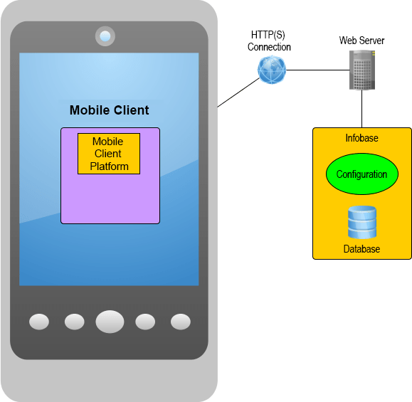
The main purpose of the mobile client is to create mobile applications with the following characteristics:
-
It must interact with the infobase in online mode.
-
The full functionality of the main application, even large-scale ones like 1C:ERP Enterprise Management must be available on the mobile device.
-
The interface must ensure comfortable usability on any mobile device, regardless of screen size or orientation.
The mobile client automatically transforms forms, described declaratively in the configuration, into the mobile version interface. Forms designed for the desktop version of 1C:Enterprise are automatically adjusted by the mobile client to ensure usability on smaller screens, like mobile phones, at an acceptable level.
In essence, the mobile client is a shell that can launch a specific application (or configuration). However, app stores may require that applications published in the store do not significantly change their functionality after publication. For this reason, you need to build the mobile client yourself and specify the list of specific configurations it can interact with during the build process. These configurations must share similar functionality.
A desktop configuration can be executed by the mobile client with minimal adjustments, mainly related to interface adaptation. For more details, refer to Mobile Client. Preparing a Configuration for Use With the Mobile Client.
Mobile Client With Offline Mode
A mobile client with offline mode is a mobile application built using the mobile client platform with offline mode. It can operate in two modes:
-
When an HTTP connection to the web server is available, it interacts with infobases online, similar to desktop client applications.
-
When no connection is available, it runs independently on the mobile device, using the configuration and data stored in the local database on the device.
When the connection is restored, data synchronization is performed between the mobile device and the server infobase.
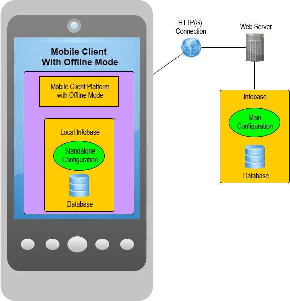
Essentially, the mobile client with offline mode is a more flexible mobile client, capable of:
-
Accessing the main infobase directly over a stable connection.
-
Operating offline when the connection to the main infobase is unavailable.
-
Providing the option to choose between online or offline modes in cases of poor connectivity.
The first launch of the mobile client with offline mode always requires an HTTP connection to the web server. During the first launch, the mobile client with offline mode retrieves the standalone configuration from the main infobase and initializes the local infobase. It must also populate the standalone database with initial data from the main infobase.
Standalone Configuration: This is a part of the main configuration that you must define during the development or enhancement of the main configuration.
A desktop configuration can be executed by the mobile client with offline mode, but it requires moderate modifications, such as defining the standalone part of the configuration and adapting the interface. For more details, refer to Mobile Client With Offline Mode. Defining the Scope of the Standalone Configuration.
Mobile Platform Application
A mobile platform application is a mobile app built using the mobile platform. It can operate independently on the mobile device.
If compared to the desktop version of 1C:Enterprise, a mobile platform application is similar to a thin client that accesses a file-based infobase, located on the same computer as the thin client.
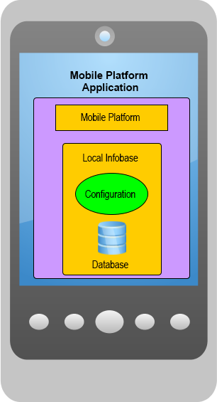
The primary purpose of a mobile platform application is to provide remote workstations for desktop applications. Most of the time, such a workstation operates independently, but it occasionally exchanges data with the main applied solution or with several back-office applications (including those not built on the 1C:Enterprise platform). You can implement this data exchange in any convenient way, for example:
-
Using HTTP services.
-
Through file exchange via email.
-
And other methods.
Typically, configurations intended for execution by the mobile platform application are designed to solve specific mobile tasks and are optimized in terms of architecture and interface for those tasks. This configuration is designed specifically for mobile usage scenarios and is convenient to use on both tablets and smartphones. For this reason, these configurations have limited functionality compared to the main application's configuration.
A desktop configuration can be executed by a mobile platform application but requires significant adjustments. For more details, refer to Mobile Platform Application - Types of Applications.
Developer Platform
Developer Platform is a special version of the mobile platform, mobile client platform, or mobile client platform with offline mode. It is designed for debugging on a mobile device and interaction with 1C:EDT during mobile configuration development.
The developer platform cannot be published in app stores. It includes all possible permissions that an application may require and provides some extended features compared to the platform used for publication.
Installing the Platform and Selecting the Development Method
First, you need to add the mobile version of the 1C:Enterprise platform to your computer and specify its location to 1C:EDT.
The parameter group Mobile Platform Versions allows you to manage the registration of mobile versions of 1C:Enterprise.

Open the Mobile Platform Versions Parameter Group
Click Window > Preferences... > V8 > 1C:Enterprise > Mobile Platform Versions.
Add a Mobile Platform Version
- Save the archive of the mobile platform version, for example
mobile_8_3_23_59.zip, to any directory. - Launch the 1C:EDT Start project.
- Open the Mobile Platform Versions parameter group.
- Click Add....
- Click File... and select the mobile platform version archive.
- Click Done.
- Click Apply and Close.
After these steps, you can use two configurations for additional software:
Launching and Debugging Android Applications
If you are developing only Android applications, you can choose one of two schemes based on your preference.
First, you can use virtual Android devices to run and debug mobile applications. In this case, only a desktop computer is required.

Second, you can run and debug a mobile application on a real Android device connected to your computer via a USB cable.

To install the required software and prepare the infrastructure for debugging, perform the following steps:
-
Install Android Studio as described in the 1C:Enterprise Documentation. Android Studio is a development environment for the Android operating system.
Important: After installing Android Studio, remember the directory where the SDK is installed: Android SDK Location. This directory will be required for configuring 1C:EDT.
-
Go to 1C:EDT and click Window > Preferences... > V8 > 1C:Enterprise > Mobile Platform Versions > Android Settings.
-
In the Android SDK Location field, enter the path noted in step 1.
-
Click Apply.
-
Click Apply and Close.
After completing these steps, you can develop a mobile application and then run and debug it. To do so:
Creating a Virtual Device in Android Studio
Android Studio includes virtual Android devices that can be used for launching and debugging mobile 1C:Enterprise applications.
To create a virtual device, follow these steps:
-
Launch Android Studio.
-
On the welcome screen, click Projects > More Actions > Virtual Device Manager > Create Device.
-
Select a category (Category) and a device name (Name), such as Phone: Galaxy Nexus, and click Next.
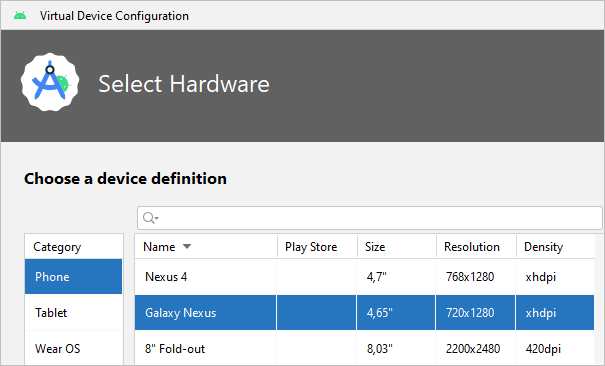
-
Download the recommended images for the API version you are using and click Next.
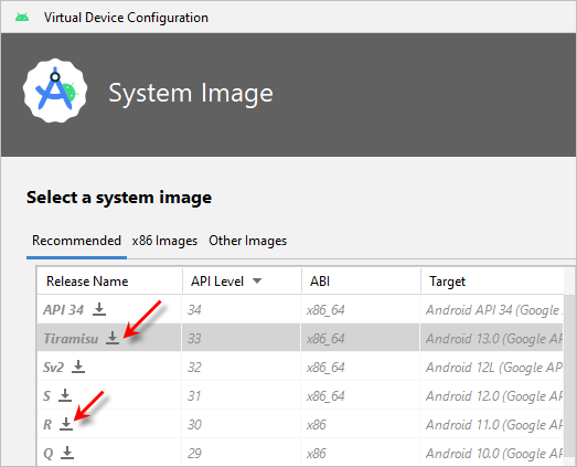
-
Set a device name (AVD Name) to help you distinguish it from other virtual devices and click Finish.
The device will appear in the list of devices in the AVD Manager.
-
Start the virtual device. by clicking
 in the Actions column.
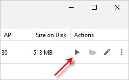
-
If you plan to run or debug a mobile application immediately, do not close or turn off the virtual device. leave it running.
Connecting an Android Device
.
To run and debug mobile 1C:Enterprise applications using Android Debug Bridge, you can use an Android device connected to your computer via a USB cable (more details).
The device must meet the system requirements (see 1C:Enterprise Documentation).
To connect the device, follow these steps:
-
Download and install the USB driver from the device manufacturer's website on your computer.
-
In the device settings, enable USB Debugging (or USB Debug).
-
Connect the device to your computer.
Depending on the version of the Android operating system and the device manufacturer, the USB Debugging setting may be located in different sections. In recent versions of Android, this setting is part of the developer mode, which is hidden by default and appears only when developer mode is enabled. The process for enabling developer mode may vary depending on the Android version and manufacturer.
To find instructions for enabling developer mode on your device and locating the USB Debugging setting, search online for device-specific guidelines.
Running a Mobile Application on a Real or Virtual Android Device Using Android Debug Bridge
To run a mobile application on an Android device, follow these steps:
-
Run the configuration as a mobile client (Mobile Client 1C:Enterprise on Android OS).
Note: If multiple devices are created or connected, 1C:EDT will open the Launch Configuration Editor. Select the desired device and click Run.
[
-
If this is the first launch on the device, 1C:EDT will install the Developer Platform. The operating system will request permissions for the platform. Click Allow.
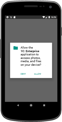
-
After installing the Developer Platform, your mobile application will also be installed and launched.

Subsequently, you can run the application manually, as well as add new applications and modify their properties.
Launching and Debugging Android and iOS Applications
If you are developing mobile applications for Android, iOS, and Windows devices, you can use the following approach:
Your computer and mobile device interact via a web server. This can be the built-in web server of 1C:EDT, a web server installed on your computer, or one that exists in the local network. The mobile device connects to the same network via Wi-Fi.
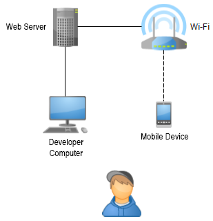
This development approach applies to mobile devices running all supported operating systems: Android and iOS.
If you are using an Android device, there is a simpler option: start the built-in web server in 1C:EDT and connect the device to your computer via a USB cable.
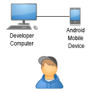
To install the required software and prepare the infrastructure for debugging, perform the following steps:
-
Install the developer platform on a mobile device:
-
Publish the mobile application on the built-in web server.
-
Create a launch configuration for the published mobile application.
-
Add the mobile application to the mobile device.
-
Debug the mobile application.
Installing Developer Platform on Android Device
Important: The Android device must meet the system requirements (see details in the 1C:Enterprise documentation).
To install the developer platform on an Android device, follow these steps:
-
Identify the data processor model installed in your Android device, its architecture (ARM or x86), and its bitness (32-bit or 64-bit).
-
Enable the Unknown Sources setting on the Android device. This setting is located in the Security section.
-
Download and install the USB driver for your Android device from the manufacturer’s website.
-
Connect the device to your computer using a USB cable.
-
Extract the mobile version of 1C:Enterprise.
-
Copy the required installation file to the Android device:
-
Developer mobile platform for various architectures:
-
ARM, 32-bit: 1cem-arm.apk.
-
ARM, 64-bit: 1cem-arm64.apk.
-
x86, 32-bit: 1cem-x86.apk.
-
x86, 64-bit: 1cem-x86_64.apk.
-
-
Developer platform for mobile clients for various architectures:
-
ARM, 32-bit: 1cem-client-arm.apk.
-
ARM, 64-bit: 1cem-client-arm64.apk.
-
x86, 32-bit: 1cem-client-x86.apk.
-
x86, 64-bit: 1cem-client-x86_64.apk.
-
-
Developer platform for mobile clients with offline mode for various architectures:
-
ARM, 32-bit: 1cem-standalone-arm.apk.
-
ARM, 64-bit: 1cem-standalone-arm64.apk.
-
x86, 32-bit: 1cem-standalone-x86.apk.
-
x86, 64-bit: 1cem-standalone-x86_64.apk.
-
-
-
Run the installation file. The developer platform will be installed, and its icon will appear in the list of installed applications as 1C:Enterprise.
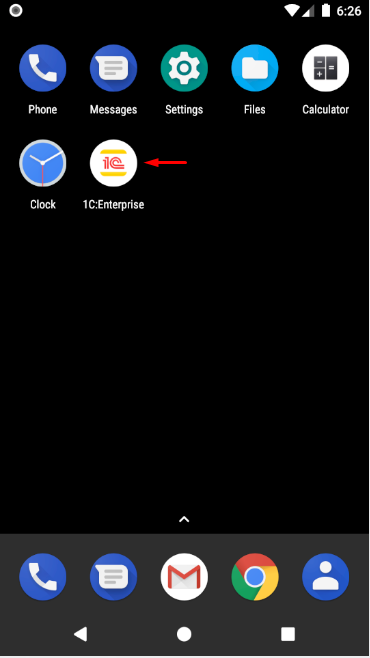
-
Disconnect the Android device from the computer.
In the future, you can launch mobile applications and add new ones.
You can find more details about installing the developer platform on an Android device in the 1C:Enterprise documentation.
Installing Developer Platform on iOS Device
You can read about installing the developer platform on an iOS device here: Mobile Development. Installing Developer Tools for iOS.
Publishing Mobile Application on Built-in Web Server
To publish a mobile application on the built-in web server, you need to enable debugging and specify the address of the debug server. To do this, follow these steps:
-
Identify the address of the local debug server. To do this:
-
Select the project you want to debug in the Navigator panel.
-
Launch the thin or thick client in debug mode.
-
Copy the debug server address to the clipboard. To do this, right-click
 Copy Stack in the context menu of the Debug panel.
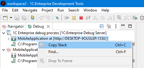
-
Save the debug server address. You will need it for creating the publication, configuring the launch configuration, and creating the mobile application on the mobile device.
-
End the debugging session. To do this, right-click
 Terminate All in the context menu of the Debug panel.
-
-
Publish the mobile application. To do this:
-
In the Navigator panel, right-click the required project and select Publish Mobile Application from the context menu.
-
In the Web Server for Publication field, select Built-in Web Server.
-
Do not change the value in the Publication Location field.
-
Select the Enable Debugging checkbox.
-
Paste the debug server address from the clipboard into the Debug URL field.
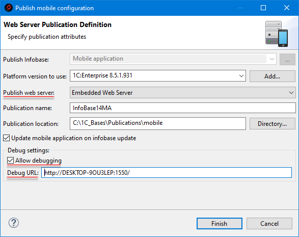
-
Click Done. The application will be published.
Tip: The publication properties are similar to the parameters used when publishing a mobile application in 1C:Enterprise Designer. For more details, see 1C:Enterprise documentation.
-
-
Save the publication address on the web server. To do this:
-
Open the Web Servers panel. To open it, click Window > Show View > Other… > 1C:Enterprise > Web Servers.
-
Expand the branch of the built-in web server in this panel and locate the publication.
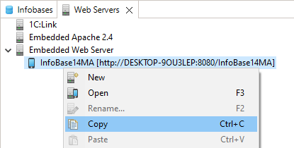
-
Right-click and select Copy from the context menu to copy the publication address on the web server.
-
Save the publication address. you will need it to create the mobile application on the mobile device.
-
Creating Launch Configuration for Published Mobile Application
.
-
Create a new launch configuration (
 > Debug Configurations...) in the Published 1C:Enterprise Mobile Application group.
 -
On the Debug Connection tab, set the following parameters.
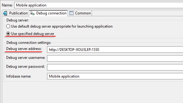
Adding Mobile Application to Mobile Device
To debug the mobile application via the web server, you need to add the mobile application to a mobile device. To do this:
-
Launch the developer platform. If no mobile applications have been added yet, you will see an empty application list.
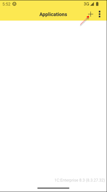
-
Click + to add a new mobile application.
-
In the Address field, enter the publication address of the mobile application on the web server (case-sensitive).
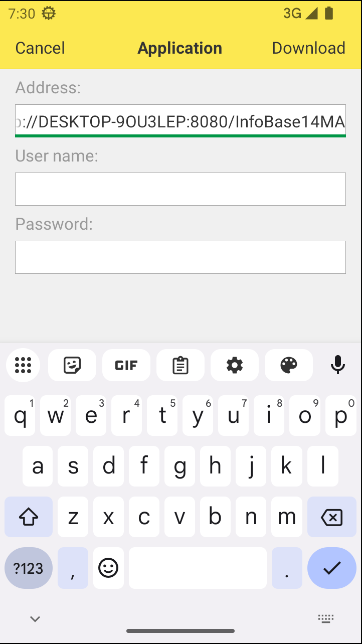
-
Click Load. The mobile application will be downloaded from the web server.
-
On the Create Application page, configure the following settings:
-
Select the Restart from Designer checkbox. This ensures that when the launch configuration is restarted in 1C:EDT, the mobile application running on the device will automatically update and restart.
-
Select the Debugging Enabled checkbox. This allows you to debug the mobile application running on the device.
-
In the Debug Server Address field, enter the local debug server address.
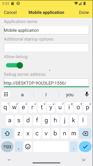
-
-
Click OK.
-
The mobile application will be loaded into the infobase and appear in the list of applications.
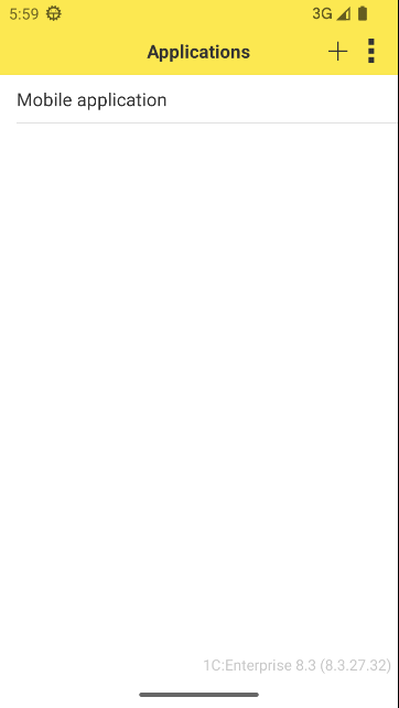
-
To launch the mobile application, click on it.
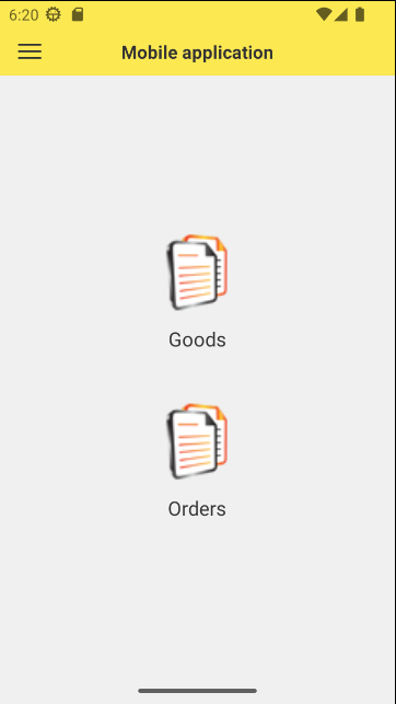
Creating a New Mobile Application Project
To create a new mobile application project, follow these steps:
-
Create a new configuration project.
By default, the new project contains a configuration designed for desktop use.
-
Modify the Usage Purposes property of the configuration. To do this:
-
Select the project in the Navigator panel.
-
In the Properties panel, open the list for the Usage Purposes property.
-
Check the box Mobile Platform Application.
You can leave or uncheck the box Platform Application.
-
Selecting or deselecting these options configures 1C:EDT for the development of a specific type of application. For example, if Mobile Platform Application is selected and Platform Application is deselected, the project will exclude object types that cannot be used in the mobile version of 1C:Enterprise.
For more information about configuration properties related to mobile application development, refer to the 1C:Enterprise Documentation.
Debugging a Mobile Application on Android OS Using Android Debug Bridge
Note: The software installation for this deployment option is described here.
Debugging Setup
To debug a mobile application, you need to (once) allow automatic connection of debug targets: client (mobile application) and server (mobile application).
If you want to debug background tasks, allow the connection of the item Background Job (Mobile Application). Instructions on how to do this can be found here.
Debugging Execution
To perform debugging:
-
Run the mobile application in debug mode (1C:Enterprise Mobile Application on Android OS).
-
Debug the items:
-
Client (mobile application).
-
Server (mobile application).
-
Background Job (Mobile Application).
-
Debugging a Mobile Application Through a Web Server
Note: The software installation for this deployment option is described here.
Debugging Setup
To debug a mobile application, you need to (once) allow automatic connection of debug targets: client (mobile application) and server (mobile application).
If you want to debug background tasks, allow the connection of the item Background Job (Mobile Application).
To do this, you need to run the previously created launch configuration of the published mobile application in debug mode, and then follow the instructions described here.
Start Debugging
To perform debugging:
-
Run the previously created published mobile application launch configuration in debug mode.
-
Launch the mobile application on the device.
-
Debug the items:
-
Client (Mobile Application).
-
Server (Mobile Application).
-
Background Job (Mobile Application).
-
Restart Debugging
Without stopping the mobile application on the device or ending the debug process, you can make changes to the mobile configuration. When you want to debug new functionality, simply run the previously created launch configuration in debug mode. The mobile application on the device will be updated and restarted.
Launching the Developer Platform and Application
To launch the developer platform on a mobile device, perform the following steps:
-
The developer platform is in the device or emulator's application list and is named 1C:Enterprise.

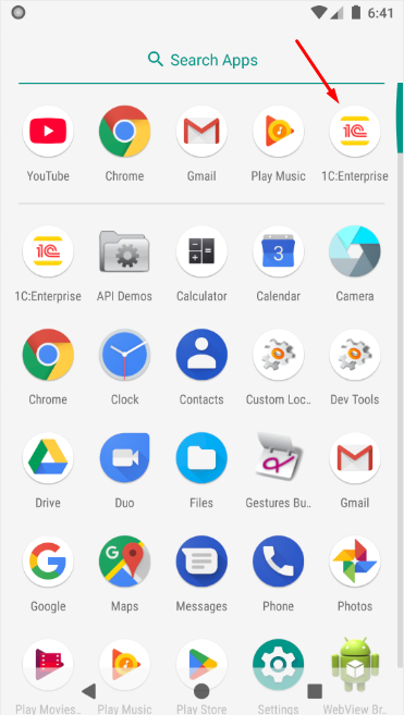
-
Click the 1C:Enterprise icon to launch the developer platform.
-
A list of mobile applications for 1C:Enterprise will open.
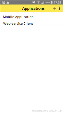
-
From the application list, select the desired application.
-
The mobile application will launch.
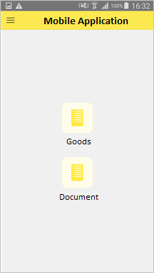
Building a Mobile Application
The final stage of mobile application development is building and distributing the app. For this, the Mobile Application Build and Publish Service is used.
This is a cloud service that allows you to migrate directly from a 1C:Enterprise application to a cloud environment where all the necessary software for building and publishing mobile applications is set up. The service offers the following advantages:
-
With internet access, you can build a mobile app in just a few minutes without delving into the nuances of mobile application development and building.
-
If desired, you can improve your skills in mobile application development. all documentation on this topic is conveniently consolidated.
-
A macOS computer is not required to build an iOS application.
-
You can install mobile applications on Android and iOS devices.
-
The only thing needed for building and publishing mobile applications is a computer with the 1C:Enterprise platform installed.
To use this service, you only need to register at developer.1c.ru.
Example: Building a Mobile Client
Launch any infobase in 1C:Enterprise mode (it can even be empty). From the system menu, select Technical Specialist Functions and run the standard data processor Mobile Application Build Service. Authenticate (or register if you do not yet have an account) on the developer.1c.ru service.
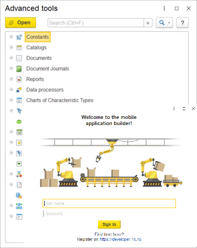
After this, you will see all the applications you have built in the top table Applications. When you select a specific application in the upper table, the bottom table Builds will show a list of all builds you have made for this application.
To start building a new application, click Create Application above the upper table.
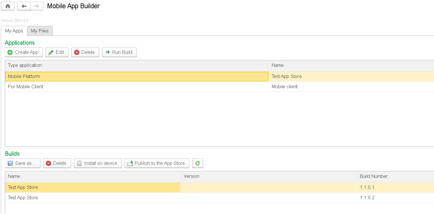
The Mobile Application Parameters wizard will open, and its first page, Start, will be active. Follow the wizard’s steps, filling in all required build parameters. On each page, click Next, or simply activate the next tab in the left-hand menu.
On the Start page, select the Simplified setup mode.
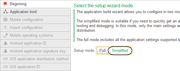
On the Application Type page, specify the type of application being built: Mobile Client.
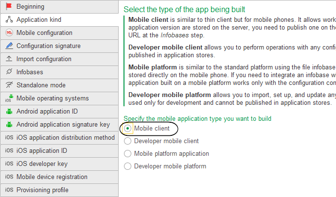
On the Mobile Configuration page, choose how to obtain the mobile configuration: Get Automatically From the Infobase.
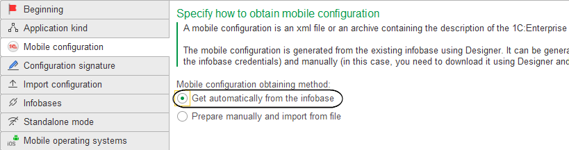
On the Configuration Signature page, set a unique signing key for the configuration, which will be embedded in the built mobile application. Keep the signing method for the configuration set to the default value Automatically for each build, and click the Create New Key button. Enter the description and password for the key, then click Create Key. Remember the password because it will be used to sign this configuration (or its future versions). The key you created will appear in the Mobile Client Signing Key field.
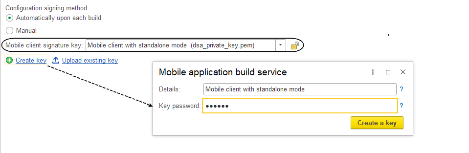
On the Load Configuration page, upload the mobile configuration that will be used to build the mobile application by clicking the Configure Infobase Connection button.
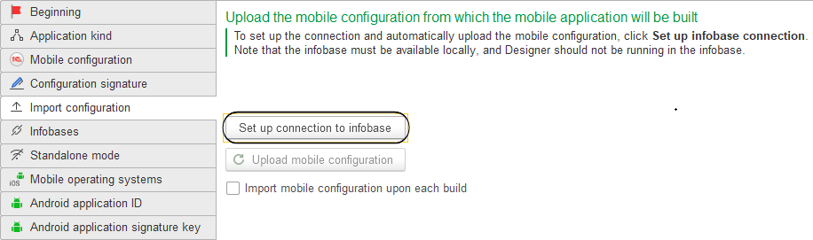
In the dialog that opens, on the Infobase tab, specify the location of the infobase containing your configuration, as well as the username and password (in this example, no password is set) for the infobase user Administrator. On the Export Platform tab, leave the platform directory unchanged unless you modified it during installation.
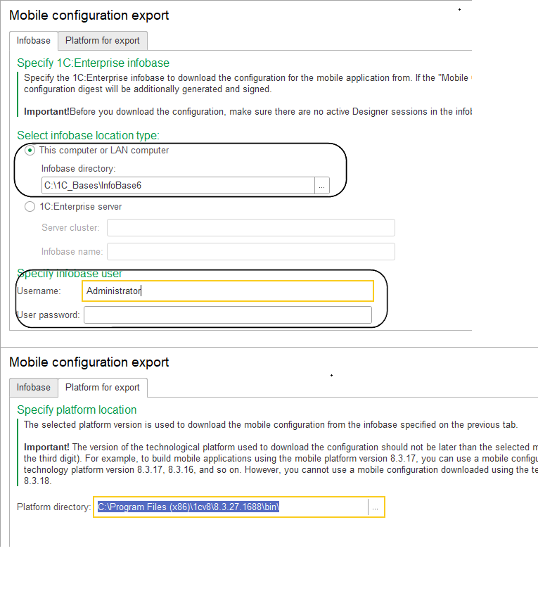
After a brief wait, the name of the uploaded mobile configuration will appear on the Load Configuration page. You can edit the name by clicking the pencil icon.
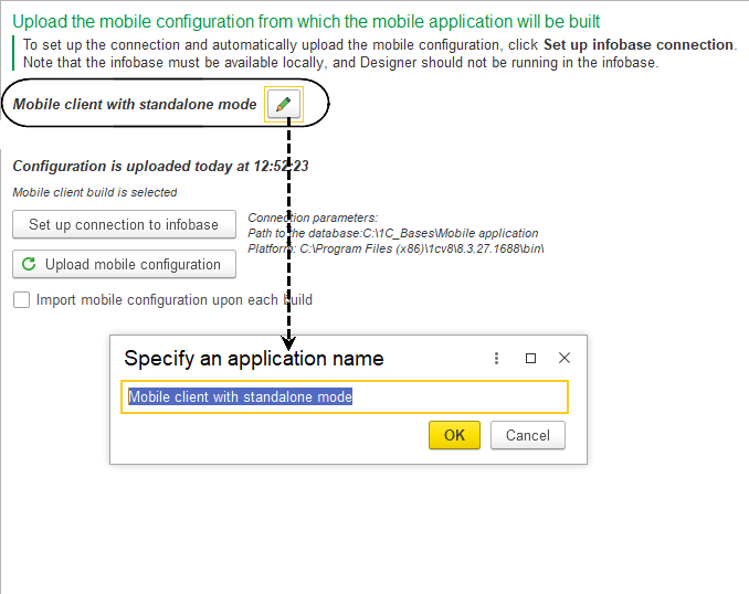
On the Infobases page, specify the address where you published the infobase on the web server (for example, http://192.168.0.105/MCA). In this case, the publication address is formatted as follows: http://
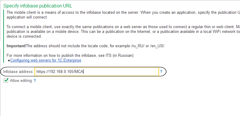
On the Offline Mode page, select the Enable Offline Mode checkbox, as you are building the application for a mobile client with offline mode.
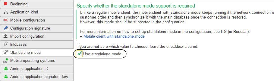
On the Mobile OS page, specify that you want to build the mobile application for the Android platform.
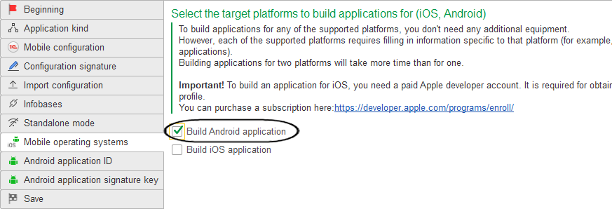
On the Android Application Identifier page, specify the string identifier of the application being built in the format
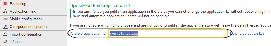
On the Android Application Signing Key page, set the signing key that will be used to sign all future versions of this application. Since this is the first time you are building the application, create a new key (make sure to remember its password), and when installing updated versions of the application, it will automatically use the same key. Click the Create New Key button. Fill in all the required fields and click Generate Key. The key you created will appear in the App Signing Key field.
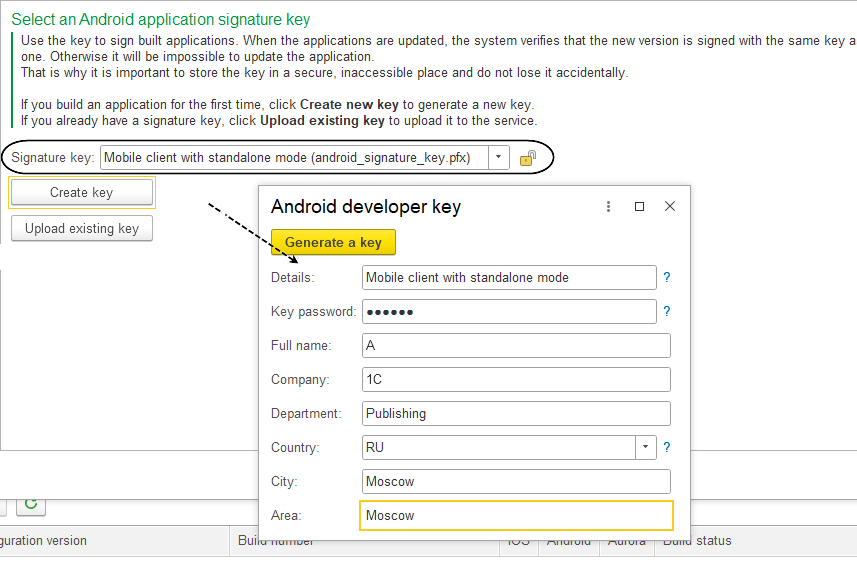
Finally, on the last page, Save, click Save Settings.
Then, click the Build button above the Applications table.
After a short wait, a row representing the built application will appear in the lower Builds table. To install the application on a mobile device, select this row and click the Install on Device button. In the window that appears, scan the QR code for the Android application or copy the link by clicking Copy Link, then transfer the link to your mobile device.
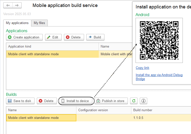
Open the received link in the browser on your mobile device and click Install/Update.
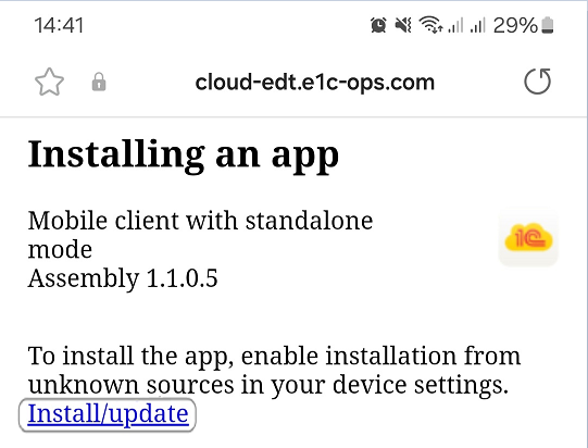
Troubleshooting: To install the application, your device must allow installations from external sources such as the internet browser.
To save the installation files to the computer used for the build, click Save to Disk, select the data processor architecture of the mobile device (e.g., ARM-64 or ARM), and click Download Application.
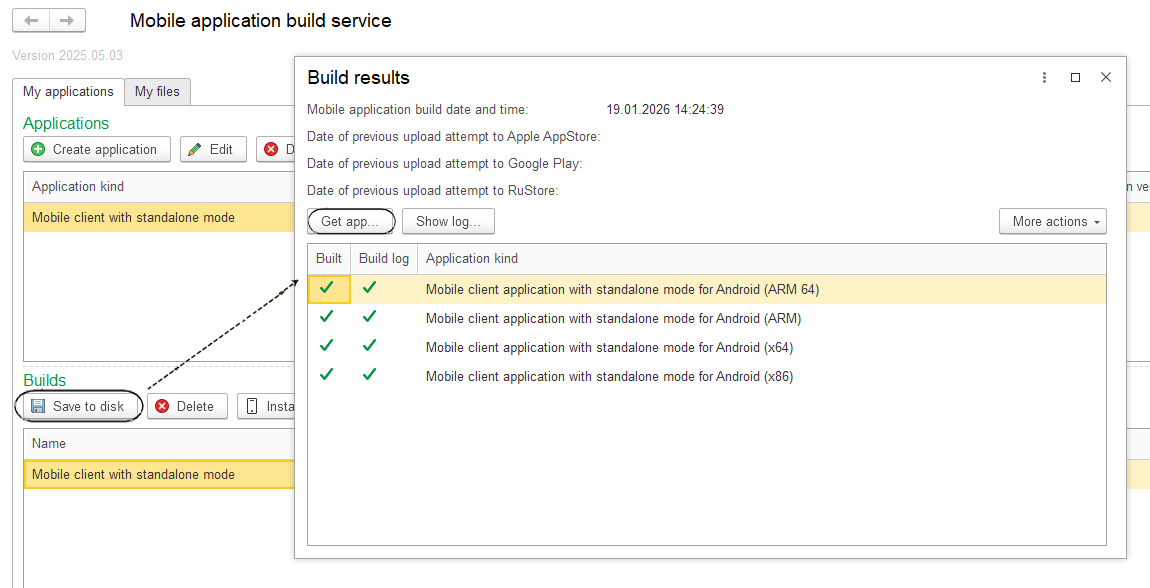
Now you are familiar with the mobile application builder and have quickly built a mobile client with offline mode.
If you plan to publish the built mobile application in an app store, you need to use the full mode of the wizard for its assembly. You can select this mode on the first step. Once all the wizard steps are completed, click Publish in Store.
If you want to fine-tune your application, select it in the upper Applications table, click Edit, and choose Full mode at the first step of the wizard. Then, go through the remaining tabs, read the detailed help information, make the necessary adjustments, and save your changes. Finally, assemble a new version of the application by clicking Build.
Tasks
Tasks
A task is an action or objective that needs to be completed. Tasks can be used to plan the scope of upcoming activities. When creating tasks, you can specify their priority level.
It is possible to link tasks to specific lines of modules. This way, you not only leave yourself a reminder of what needs to be done, but you can also quickly navigate to the place where these actions need to be run.
Tasks Panel
The Tasks panel displays a list of tasks to be completed or already completed.
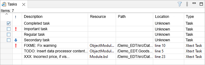
This panel is part of the default perspectives Synchronize and Files. Some tasks appear in the panel automatically, while others are created manually.
1C:EDT automatically creates tasks based on comments in the modules. The lines containing //TODO, //FIXME, and //XXX are selected for task creation.
Developers typically use the //TODO comment to mark incomplete code fragments that need to be revisited later. 1C:EDT also uses such comments when generating code fragments automatically. For example, when creating an event handler template, it inserts the comment //TODO: Insert handler code.
The //FIXME comment is usually used by developers to mark identified errors that need to be fixed later.
The //XXX comment is typically used to mark critical errors that must be fixed before development can continue.
Open the Tasks Panel
Click Window > Show View > Other… > General > Tasks.
Legend
 High-priority task.
 Low-priority task.
 Incomplete task.
 Completed task.
Columns
- Completed: Indicates whether the task is completed or not .
- Priority: Shows the task priority: high , normal (no icon), or low .
- Description: Displays the task description.
- Files: Displays the name of the file linked to the task.
- Path: Displays the file path linked to the task.
- Location: Indicates the line number in the module linked to the task.
- Type: Specifies the type of task: Task for manually created tasks or Xtext Task for automatically created tasks.
- Creation Time: Displays the task's creation time.
Mouse Actions
- A single click on the column header sorts the list by this column. If already sorted, clicking changes the sorting direction.
- Clicking with Ctrl or Shift selects multiple rows for copying information, marking as completed, or deleting.
- Clicking the Completed cell toggles the task's completion status.
- Clicking the Priority cell opens a menu to change the task's priority
 .
. - Clicking the Description cell when Type equals Task allows editing the task description.
- Double-click on a row:
- for tasks where Files and Path are filled, opens the module linked to this task in the 1C:Enterprise Language Editor and positions the cursor on the linked line
Command Bar
 (Filters) Opens a dialog that allows you to display only specific tasks instead of all. Filtering by priority, description, type, and other parameters is available. You can also limit the number of displayed tasks.
- (Show Menu) Opens a drop-down menu containing additional commands for the panel.
- Show submenu contains the following commands:
- TODOs displays only tasks created from comments containing
// TODO - Show All removes applied filters and displays all tasks
- TODOs displays only tasks created from comments containing
- Column Settings... opens a dialog that allows you to configure the composition, order, and width of the list columns
- Show submenu contains the following commands:
Context Menu
- Go to Resource: For tasks where Files and Path are filled, opens the module linked to this task in the 1C:Enterprise Language Editor and positions the cursor on the linked line.
- Copy: Copies the names of columns and values of fields of the selected task to the clipboard.
- Copy Details submenu contains the following commands:
- Description copies the task description to the clipboard
- Full Resource Name copies the values of fields Path and Files to the clipboard
- Delete deletes selected tasks. Available only for manually created tasks.
- Properties opens a dialog that allows you to edit task properties.
Add or Remove a Task Linked to a Module
Add a Task Linked to a Module
In the 1C:Enterprise Language Editor, click Add Task... in the context menu of the vertical margin.
The fields Element, Path, and Location will be automatically populated and unavailable for editing.
Remove a Task Linked to a Module
A task linked to a module can be removed in two ways:
- In the 1C:Enterprise Language Editor, click Remove Task in the context menu on the task icon in the vertical margin.
- In the Tasks panel, click Remove in the task's context menu.
Add or Remove a Task Not Linked to a Module
Add a Task Not Linked to a Module
In the Tasks panel, click Add Task... in the context menu.
The fields Element, Folder, and Location will remain empty and unavailable for editing.
Remove a Task Not Linked to a Module
Click Remove in the task's context menu.
Navigate to a Module Line Linked to a Task
To navigate to the module line linked to a task, double-click the task.
The Result of Desktop Application Development
Configuration File
In the simplest case, the development result is a .cf configuration file. This file contains the application without data.
To create a .cf configuration file:
-
Ensure the linked infobase contains the latest version of the configuration being developed. To do this:
-
In the Navigator panel, right-click the project and select Update Configuration... from the context menu.
-
Check the box Load Full Configuration... and click Done.
This will perform a complete load of the configuration into the infobase.
-
-
In the Navigator panel, right-click the project and select Show Infobase
from the context menu. The Infobases panel will open, highlighting the infobase associated with the project.
-
Click Save Configuration to File... in the context menu of the base.
-
Specify the location to save the .cf file and click Done.
With the .dt file, users can:
-
Create an infobase without a configuration.
-
Launch it in Designer mode.
-
Upload the .cf file into the infobase.
Then the user can run this infobase in 1C:Enterprise mode.
Infobase Dump File
The result can also be a .dt infobase file. containing the application with data This file is useful for providing demonstration data alongside the solution.
To create a .dt infobase file:
-
Ensure the linked infobase contains the latest version of the configuration being developed. To do this:
-
In the Navigator panel, right-click the project and select Update Configuration... from the context menu.
-
Check the box Load Full Configuration... and click Done.
This will perform a complete load of the configuration into the infobase.
-
-
In the Navigator panel, right-click the project and select Show Infobase
from the context menu. The Infobases panel will open, highlighting the infobase associated with the project.
-
Right-click on the infobase and select Dump Infobase....
-
Specify the location for the .dt file to be created and click Done.
With the .dt file, users can:
-
Create an infobase without a configuration.
-
Launch it in Designer mode.
-
Upload the .dt file into the infobase.
Then the user can run this infobase in 1C:Enterprise mode.
Configuration Delivery File and Configuration Update File
When creating mass-distributed applications, it is insufficient to simply provide the user with a .cf configuration file. Your application will evolve, and new versions will be released, requiring the user to manually update their application to the latest version. This process can be complex and may lead to errors.
To enable automatic or semi-automatic application updates to a new version, the 1C:Enterprise platform includes a delivery and configuration support mechanism, see 1C:Enterprise documentation for details.
This mechanism allows you to create a special .cf configuration delivery file. If a user's infobase is created using such a file:
-
Firstly, the user will not be able to accidentally make changes to the configuration, to do so, the support mode must first be changed.
-
Secondly, configuration updates will be installed automatically or with user interaction depending on the support mode.
-
Thirdly, application updates are created as a .cfu file. This file does not contain the entire application, only the modified parts.
Configuration Delivery File
To create a .cf configuration delivery file, follow these steps:
- Fill in the following configuration properties:
- Vendor
- Version
- Ensure the linked infobase contains the latest version of the configuration being developed. To do this:
- In the Navigator panel, right-click the project and select Update Configuration... from the context menu.
- Check the box Load Full Configuration... and click Done.
This will perform a complete load of the configuration into the infobase.
- In the Navigator panel, right-click the project and select Show Infobase <infobase name> from the context menu.
The Infobases panel will open, highlighting the infobase associated with the project.
- Right-click on the infobase and select Run Designer.
- Create a .cf configuration delivery file.
A user with a .cf configuration delivery file can:
- Create an infobase without a configuration.
- Launch it in Designer mode.
- Upload the file into the infobase.
Then the user can run this infobase in 1C:Enterprise mode.
Configuration Update File
To create a .cfu configuration update file, follow these steps:
- Ensure the linked infobase contains the latest version of the configuration being developed. To do this:
- In the Navigator panel, right-click the project and select Update Configuration... from the context menu.
- Check the box Load Full Configuration... and click Done.
If the configuration was never delivered before, you must first do so.
- Fill in the following configuration properties:
- Vendor
- Version
- In the Navigator panel, right-click the project and select Show Infobase <infobase name> from the context menu.
The Infobases panel will open, highlighting the infobase associated with the project.
- Right-click on the infobase and select Run Designer.
- Create a .cfu configuration update file.
Distribution Package
Regardless of the types of files you deliver (.cf configuration file, .cf configuration delivery file, or .dt infobase file), the following features may be needed:
-
Include multiple files (for different applications) in the delivery.
-
Add supplementary files (reference or explanatory).
-
Provide an executable file to install delivered applications as templates. Users can then create new infobases from these templates without using Designer.
The distribution package function facilitates these capabilities. A distribution package is a .zip archive that contains:
-
The 1cv8.efd file: includes the .cf configuration delivery file, .cfu configuration update file, and .dt infobase file.
-
Supplementary files.
-
Executable files for launching on different operating systems:
-
For Windows: setup.exe.
-
For Linux: setup.
-
For macOS: the setup.app directory, recognized by the operating system as an installation application.
-
See 1C:Enterprise documentation for more details on distribution packages.
One possible application delivery setup includes:
-
A .cf configuration delivery file: this template allows users to create an infobase intended for accounting operations.
-
A .dt infobase file: this template allows users to create a demo infobase showcasing the application with prepared data.
To create a distribution package, follow these steps:
-
Fill in the following configuration properties:
-
Vendor
-
Version
-
-
Ensure the linked infobase contains the latest version of the configuration being developed. To do this:
-
In the Navigator panel, right-click the project and select Update Configuration... from the context menu.
-
Check the box Load Full Configuration... and click Done.
This will perform a complete load of the configuration into the infobase.
-
-
Launch the application and create the demo data you want to provide to the user.
-
Once the configuration and data are ready, start forming the distribution package. In the Navigator panel, right-click on the project and select Show Infobase
. The Infobases panel will open, highlighting the infobase associated with the project.
-
Right-click on the infobase and select Run Designer.
-
Create a distribution package.
A user with a distribution package can, for example, in Windows:
-
Extract the archive.
-
Run the setup.exe file:
-
Click Next twice, then Done.
As a result, templates for configurations contained in the distribution package will be installed.
-
Create an infobase from a template.
Installation Package
In 1C:Enterprise 8, installation packages of delivered solutions can be created using the Autorun application. This application is a customizable user interface for creating CDs or DVDs.
If the application is delivered on a disc, the user inserts the disc, and autorun starts automatically. If the application is delivered as a set of files, the user must manually launch the autorun file. Using a dialog, the user selects an installation option, views supplementary files, or installs additional software.
See 1C:Enterprise documentation for more details on the Autorun application.
To create an installation package for the delivered application (e.g., for Windows), follow these steps:
-
Create a distribution package and extract it, for example, into the application directory.
-
Prepare the 1C:Enterprise platform installation package to be delivered with your solution, and place it in the platform directory.
-
Prepare additional files, e.g., in the additional directory.
-
Download the Autorun application files and extract them, for example, into the distr directory.
-
Download images for the Autorun dialog, extract them into the Pictures directory, and place this directory in distr.
-
Run autorun.exe to review the demo example.
-
Place the application, platform, and additional directories into the distr directory.
-
Edit the autorun.lst file (first menu page) and the autorunfull.lst file (second menu page, Custom Installation... option) as needed. You can also add additional pages by following the autorunfull.lst structure (more details).
-
Edit the SetupV8.cfg file: it provides a quick installation of the application, platform, two configuration templates (with and without data), and two infobases based on these templates (more details).
Delivery Scenarios for the 1C:Enterprise System
Run an Infobase in Designer Mode
In Designer mode, you develop applications and manage infobases.
To run an infobase in Designer mode:
-
Launch the 1C:Enterprise platform.
-
Select the infobase you want to interact with.
-
Click Designer.
Troubleshooting: If you are launching the infobase in this mode for the first time, the configuration structure will be hidden. To display it click Configuration > Open Configuration.
Run an Infobase in 1C:Enterprise Mode
The 1C:Enterprise mode is the main mode of the 1C:Enterprise system. In this mode, users (as opposed to administrators and developers) perform their tasks. In this mode, users add, modify, and delete data, generate reports, and perform other application-level tasks.
To launch an infobase in 1C:Enterprise mode, perform the following steps:
-
Launch the 1C:Enterprise platform.
-
Select the infobase you want to interact with.
-
Click 1C:Enterprise.
Create a File-Based Infobase Without a Configuration
To create a file-based infobase without a configuration, follow these steps:
-
Launch the 1C:Enterprise platform.
-
Click Add....
-
Select Create New Infobase and click Next.
-
Choose Create Infobase Without a Configuration... and click Next.
-
Provide a name for the infobase to distinguish it from others on your computer.
-
Select On This Computer or LAN Computer and click Next.
-
Click Next, then Finish.
Create a File-Based Infobase From a Template
To create a file-based infobase from a template:
-
Launch the 1C:Enterprise platform.
-
Click Add....
-
Select Create New Infobase and click Next.
-
Choose Create Infobase From Template, select the desired template, and click Next.
-
Provide a name for the infobase to distinguish it from others on your computer.
-
Select On This Computer or LAN Computer and click Next.
-
Click Next, then Finish.
Load a Configuration From a .cf File
This scenario assumes the target infobase either does not have a configuration or contains an existing configuration and data you are ready to overwrite.
Important: To complete this task, the infobase must be running in Designer mode.
To load a configuration from a .cf file:
-
Click Configuration > Load Configuration From File....
-
Select the .cf file and click Open.
If the infobase already contains a configuration, confirm the replacement
-
by clicking Yes.
The configuration from the .cf file will be loaded into the infobase as the main configuration. Designer will ask to update the database configuration:
-
Click Yes.
Confirm the database restructuring
-
by clicking Accept.
The database configuration will be updated.
Load Infobase from a .dt File
In this scenario, it is assumed that the infobase into which the .dt file will be loaded either does not contain a configuration or contains a configuration and data that are no longer needed, and you are ready to delete them.
Important: To complete this task, the infobase must be running in Designer mode.
-
Click Administration > Load Infobase....
-
Select the .dt file and click Open.
A warning will appear stating that Designer will be closed.
-
Click Yes.
The infobase will be loaded. A prompt will appear to restart Designer.
-
Click Yes.
Designer will restart with the new infobase.
Create a .cf Configuration Delivery File
Important: To complete this task, the infobase must be running in Designer mode.
To create a .cf configuration delivery file, follow these steps:
-
Click Configuration > Distribute Configuration > Create Distribution Package and Configuration Update File....
-
Select the checkbox for Create a Delivery File.
-
Specify the location for the .cf configuration delivery file to be created and click Execute.
-
Click OK.
Create a .cfu File for Configuration Update
Important: To complete this task, the infobase must be running in Designer mode.
To create a .cfu configuration update file, follow these steps:
-
Click Configuration > Distribute Configuration > Create Distribution Package and Configuration Update File....
-
Select the checkbox for Create a Configuration Update File Update File.
-
Specify the location for the update .cfu file to be created and click Execute.
-
In the Update Configurations list, add the .cf configuration delivery file with the previous version of your application.
-
Click Execute.
-
Click OK.
Update Configuration Using a .cfu File
Important: To complete this task, the infobase must be running in Designer mode.
To update the configuration using a .cfu file, follow these steps:
-
Click Configuration > Support > Update Configuration....
-
Select the option Select Update File and click Next.
-
Choose the .cfu File and click Finish.
-
Click OK.
The main configuration will be updated. A prompt will appear to update the database configuration.
-
Click Yes.
Information about database restructuring will be displayed.
-
Click Accept.
Create a distribution package From the Current Infobase
Important: To complete this task, the infobase must be running in Designer mode.
To create a distribution package from the current infobase, follow these steps:
-
Click Configuration > Distribute Configuration > Distribution Package....
-
Select the option Create Distribution Package Description and click OK.
-
Click Next twice, then Finish.
-
Click Create Package Archive.
-
Click Yes.
-
Choose a directory to save the distribution package description and click Save.
-
Select the directory where the distribution package archive will be saved, and click Save.
Export Configuration to Files
Important: To complete this task, the infobase must be running in Designer mode.
-
Click Configuration > Export Configuration to Files....
-
Export to: choose one of the export options. Both options are suitable for subsequent import into 1C:EDT:
-
XML Files: Select this option to export the configuration as a hierarchical structure of .xml files and specify the directory where the files will be stored.
-
Archive: Select this option to place all exported files into an archive and specify the path to the archive file.
-
-
In the input field, select the directory where the export files or archive will be placed.
-
Execute on Server: if Designer is launched for a client-server infobase, this checkbox becomes available and allows you to specify that the export will be executed on the server. In this case, multiple system background tasks will be used.
-
Number of Export Tasks: If set to 0, the 1C:Enterprise platform will automatically determine the number of system background tasks required for exporting the client-server infobase. Otherwise, you can specify the number of tasks manually.
-
Do Not Export Links to Nonexistent Objects: The configuration structure may contain links to configuration objects that were previously removed. These links lead nowhere and should ideally not exist in a perfect configuration. Selecting this checkbox will prevent such links from being exported.
-
-
Click Export.
The export progress can be monitored in the status panel at the bottom of Designer. No informational messages are displayed upon completion of the export.
Load Configuration From Files
Important: To complete this task, the infobase must be running in Designer mode.
-
Click Configuration > Load Configuration From Files....
-
Load from: choose one of the import options. Both options are suitable for subsequent import into 1C:EDT:
-
XML Files: Select this option if the project was exported to .xml files.
-
Archive: Select this option if the project was exported to an archive.
-
-
In the input field, select the directory where the export files or archive are located.
-
-
Click Load.
The import progress can be monitored in the status panel at the bottom of Designer. No informational messages are displayed upon completion of the import.
Chapter 5. Configuration
Building an Application Based on a Model
The 1C:Enterprise system is designed with a strict orientation toward building an application based on a specific model.
A model refers to the entire concept of application development. This includes methods for structuring data, types of relationships between data, principles of data manipulation, ways to describe business logic, methods for linking data to interface objects, functional separation across system levels, and more.
For example, defining certain objects (entities) in a configuration immediately determines both the related 1C:Enterprise language types and the necessary database structures for storing them. All subsequent operations with these objects, both in memory and in the database, are run consistently, without the need to overcome "barriers" between different notations used, for example, when using a DBMS and general-purpose programming languages.
In 1C:Enterprise, the entire application is described as a configuration. The configuration is a collection of applied objects selected from a strictly defined set of classes.
Each such configuration object class represents a specific set of objects or processes within the subject area, sharing similar behavioral characteristics and playing a similar role in the overall solution structure.
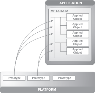
Examples of such classes include Catalogs, Documents, and Accumulation Registers. Each configuration object class has a base implementation. It defines the operational characteristics of objects created based on this class.
-
The structure of stored entities, including some predefined fields.
-
A set of 1C:Enterprise language types.
-
Methods, properties, and events, as well as typical operations relevant to the task.
-
Display and editing methods.
-
Access rights management methods, among others.
If, during development, you need to create a logical object reflecting subject area specifics, you simply select the appropriate class and create a configuration object based on it. You can then define various properties that determine the behavior of the created object, extend the data structure if necessary, implement the required set of methods, define event handlers, and refine how the configuration object is displayed in the interface.
For simple configuration objects, this refinement may not be necessary at all, reducing the entire creation process to specifying its name. In more complex cases, it is possible to define data structures and business logic algorithms in detail while the standard functionality is implemented automatically without any additional effort.
It is important to note that the number of configuration object classes in 1C:Enterprise 8 is relatively small, approximately two dozen. They are easy to learn and can be effectively applied to solve any subject area tasks. Thus, a configuration is not just a set of object descriptions in specific unified terms. The entire application consists of objects clearly divided according to the roles they play in the business application. This relatively compact set is sufficient to cover all subject area needs. The set of available prototypes in 1C:Enterprise imposes a standard design model, significantly reducing the costs of building and maintaining applications.
Hierarchy of Configuration Objects
A configuration is structured as a tree within a configuration project or a configuration extension project. External Reports and Data Processors Project also contains a configuration object tree, but in a reduced form, with only two branches: Reports and Data Processors.
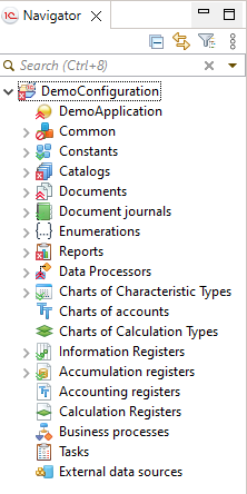
Configuration
The first branch of the tree represents the configuration itself, the entire application.
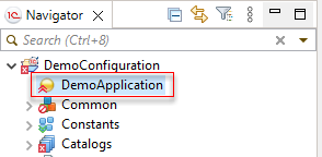
Using the context menu commands for this branch, you can edit application-wide properties and elements related to the entire applied solution, such as the managed application module, command interface, workspace of the start page, and so on.
General-Purpose Objects
The next branch, General, contains general-purpose configuration objects, grouped by their classes.
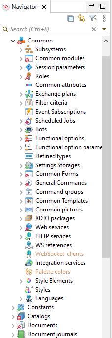
Applied Objects
Following the General branch are the applied configuration object classes. Since they primarily define the applied functionality of the solution, these branches are placed at the top level of the hierarchy to facilitate access.
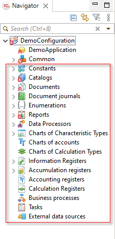
Objects of the same applied class are located in their respective branches, and each configuration object is uniquely identified by its name within its class. Objects can be sorted alphabetically or in any order that is convenient for you.
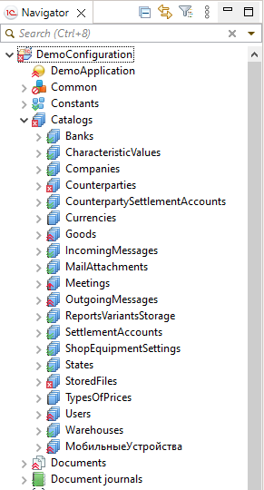
Subordinate Metadata Objects
All configuration objects have an internal structure, which is also displayed in the configuration tree. Many elements of the internal structure are standardized across different object classes. For example, catalogs, documents, and other objects can have tabular sections. Nearly all configuration objects can have attributes. Such elements of the internal object structure are called subordinate metadata objects. Metadata objects used by a configuration object are also grouped by their classes: attributes, tabular sections, forms, commands, templates, and so on.
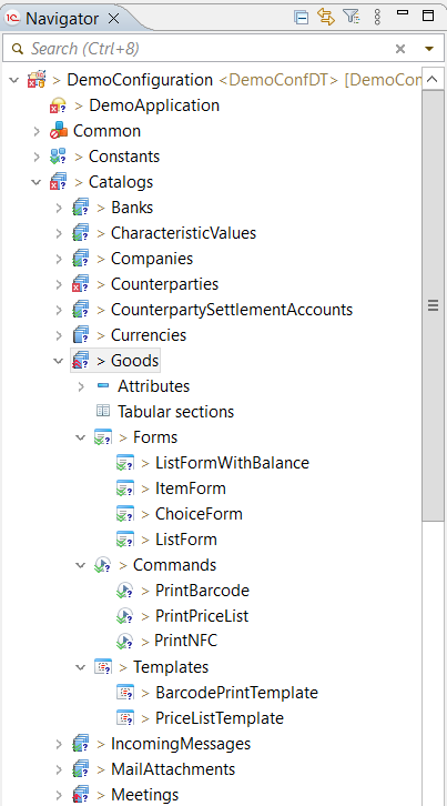
More details about the configuration tree can be found in the 1C:Enterprise documentation.
Applied Configuration Objects
Business Process
A business process is the core element of the business process mechanism. It is intended to define business logic within a flowchart and manage the lifecycle of created business processes (instances) from start to completion.
An essential characteristic of a business process is its connection to a task, which establishes the addressing system and enables the design of flowcharts following the organizational structure supported in the application.
More details about business processes can be found in the 1C:Enterprise documentation.
External Data Source
An external data source is used to describe an external database (either relational or analytical) from which information will be used in 1C:Enterprise in various ways, such as in reports or for specific calculations.
An external data source may include tables from a relational data source and cubes from an analytical data source.
More details about external data sources can be found in the 1C:Enterprise documentation.
Document
A document is designed to record a specific business operation with a reference to date and time. This ensures a strict chronological order of operations.
Documents can be used as digital equivalents of standard paper documents that serve as the basis for accounting transactions or calculations.
More details about documents can be found in the 1C:Enterprise documentation.
Document Journal
A document journal displays documents of different types in a single list.
More details about document journals can be found in the 1C:Enterprise documentation.
Task
A task is an element of the business process mechanism. It allows tracking assignments by executors and reflects the progress of a business process through route points. Tasks can be created not only by business processes but also by other infobase objects and directly by users.
More details about tasks can be found in the 1C:Enterprise documentation.
Constant
Constants are used to store persistent (or conditionally persistent) information that applies to the entire applied solution. For example, an organization's name, which typically does not change or changes infrequently.
More details about constants can be found in the 1C:Enterprise documentation.
Numerator
A numerator defines the numbering rules for documents. All documents associated with a specific numerator will have sequential numbering according to these rules.
More details about numerators can be found in the 1C:Enterprise documentation.
Data Processor
A data processor is used to perform various operations on the data stored in the application, such as importing information, deleting outdated data, performing scheduled operations, and similar tasks.
More details about data processors can be found in the 1C:Enterprise documentation.
Report
A report provides summarized information about the data stored in the application. It includes algorithms for retrieving and processing information, as well as forms for entering initial parameters and displaying results.
More details about reports can be found in the 1C:Enterprise documentation.
Enumeration
An enumeration stores a fixed set of values that are typically used during interactive operations within the application. For example, an enumeration CounterpartyTypes may contain values such as Organization and Individual. When creating new counterparties, the user selects one of these values.
More details about enumerations can be found in the 1C:Enterprise documentation.
Chart of Calculation Types
The chart of calculation types is an element of the complex periodic calculation mechanism. It is used to define calculation types and their interdependencies.
More details about chart of calculation typess can be found in the 1C:Enterprise documentation.
Chart of Characteristic Types
The Chart Of Characteristic Types is designed to create a structure for storing "attributes" that are defined not during development but by users during application use. For example, if a developer has only provided the attributes Vendor and Name for goods, a user can independently create additional attributes (characteristic types) such as Color and Size and track goods accordingly.
Additionally, the chart of characteristic types is used in the accounting mechanism to manage analytical accounting. It defines the types of objects for which detailed financial information can be obtained, such as fixed assets, intangible assets, materials, organizations, accountable persons, contracts, budgets, and so on.
More details about chart of characteristic types can be found in the 1C:Enterprise documentation:
Chart of Accounts
A chart of accounts is an element of the accounting mechanism. It is used to define a set of synthetic accounts that group financial activity information. By configuring the chart of accounts, the required accounting system is organized.
More details about charts of accounts can be found in the 1C:Enterprise documentation.
Sequence
A sequence is used to restore accounting data after backdated document corrections. It allows for the reprocessing of all documents included in it in strict chronological order.
More details about sequences can be found in the 1C:Enterprise documentation.
Accounting Register
The accounting register is the main element of the accounting mechanism. It allows for multi-level and multi-dimensional analytical accounting, accounting across multiple charts of accounts, as well as quantity, sum, and currency accounting in various analytical contexts.
More details about accounting registers can be found in the 1C:Enterprise documentation.
Accumulation Register
The accumulation register is used to store and aggregate numerical data in a multi-dimensional measurement system. For example, it can track inventory balances by item and warehouse or record sales volumes by item and company division.
More details about accumulation registers can be found in the 1C:Enterprise documentation.
Calculation Register
The calculation register is the main element of the complex periodic calculation mechanism. It is used to store records of different calculation types that need to be executed, as well as intermediate data and final calculation results.
More details about calculation registers can be found in the 1C:Enterprise documentation.
Information Register
The information register is used to store data across multiple dimensions. For example, an information register can store prices by item, price type (wholesale, retail), and price change date.
More details about information registers can be found in the 1C:Enterprise documentation.
Catalog
A catalog is used to store permanent or conditionally permanent information with a defined set of values. Catalogs can be used to store data such as lists of materials, goods, organizations, currencies, employees, and more.
More details about catalogs can be found in the 1C:Enterprise documentation.
General-Purpose Configuration Objects
HTTP Service
An HTTP service defines a service whose functionality is provided by the application. Each HTTP service may contain one or more templates. For each template, one or more methods can be created to handle data processing. For each method, the HTTP method to be processed is specified, and a procedure in the 1C:Enterprise language is created to handle the data. It is also possible to specify that any available HTTP method can be processed rather than a specific one.
More details about HTTP services can be found in the 1C:Enterprise documentation.
Web Service
A web service describes a web service provided by the 1C:Enterprise application. A web service contains a set of operations. Each operation may have a number of parameters for transmitting data to the web service and receiving return values. The parameter types and return values of web services are described using the XDTO mechanism. The web service configuration object contains a module where procedures are executed when specific web service operations are called.
More details about web services can be found in the 1C:Enterprise documentation.
WS Reference
A WS reference is used to define a "static" reference to an external web service from a third-party provider within the application. A WS reference represents a WSDL description of the web service, imported from the specified source. A WS reference cannot be edited, but its structure and the structure of the data types used for describing parameters and return values can be viewed.
More details about WS references can be found in the 1C:Enterprise documentation.
Command Group
A command group allows you to group certain commands separately in the function panel of the current section, in addition to the standard groups Create, Reports, and Service.
More details about command groups can be found in the 1C:Enterprise documentation.
Filter Criterion
A filter criterion allows you to quickly create lists of information related to a specific data element without programming. For example, a list of all documents in which a particular counterparty was a supplier or buyer of goods.
More details about filter criteria can be found in the 1C:Enterprise documentation.
Common Picture
A common picture is one or more (archived) graphic images used in form elements, templates, and other parts of the application.
More details about common pictures can be found in the 1C:Enterprise documentation.
Common Command
A common command defines an action intended for execution by the user. This action applies to the entire application (such as importing data) or an operation with a configuration object that does not use standard commands.
More details about common commands can be found in the 1C:Enterprise documentation.
Common Form
A common form is a form that does not belong to a specific configuration object but serves its own purpose within the application as a whole. A common form may also be used by multiple configuration objects to perform specific tasks.
More details about common forms can be found in the 1C:Enterprise documentation.
Common Template
A common template stores data used by multiple configuration objects or the entire application. This may include a print form template, binary data, a Microsoft Word document template, an HTML document, and more.
More details about common templates can be found in the 1C:Enterprise documentation.
Common Module
Common modules are the only modules in the configuration tree that exist as separate independent objects (more details).
Common Attribute
A common attribute is used for two purposes. First, to identify isolated data areas when the configuration operates in data separation mode. Second, to create identical attributes that are present in many configuration objects. For example, the attributes Author and Editor, which should be included in all documents.
More details about common attributes can be found in the 1C:Enterprise documentation.
User-Defined Type
A user-defined type can be used to generate a new data type. The generated data type can then be used as the type for other data (attributes, dimensions, etc.).
More details about user-defined types can be found in the 1C:Enterprise documentation.
XDTO Package
An XDTO package allows you to define a system of types and values for interacting with various external data sources, such as web services.
More details about XDTO packages can be found in the 1C:Enterprise documentation.
Session Parameter
Session parameters are used to store persistent values specific to the current session, which are frequently used in program algorithms.
More details about session parameters can be found in the 1C:Enterprise documentation.
Functional Option Parameter
A functional option parameter is part of the functional options mechanism. It allows the creation of functional options where the outcome is not fixed at implementation but can change depending on the data stored in the infobase (based on the functional option parameter's value).
More details about functional option parameters can be found in the 1C:Enterprise documentation.
Exchange Plan
An exchange plan is used to define the structure of a distributed information system and data exchange algorithms. It contains information about the nodes involved in data exchange, defines the dataset for exchange, and determines whether the distributed infobase mechanism should be used.
More details about exchange plans can be found in the 1C:Enterprise documentation.
Event Subscription
An event subscription allows you to assign an additional handler to a particular event for multiple objects of the 1C:Enterprise language, whether they belong to the same or different configuration object classes. The event handler executes first, followed by the additional handlers assigned through subscriptions.
More details about event subscriptions can be found in the 1C:Enterprise documentation.
Subsystem
Subsystems are used to form the application's global command interface. The subsystem structure presents users with an overview of the application's functionality.
More details about subsystems can be found in the 1C:Enterprise documentation.
Scheduled Job
A scheduled job is an element of the job mechanism. It enables the automatic execution of procedures in the 1C:Enterprise language according to a schedule.
More details about scheduled jobs can be found in the 1C:Enterprise documentation.
Role
Roles define sets of permissions that allow users to perform specific actions. Each application user is assigned one or more roles, determining their access rights within the application.
More details about roles can be found in the 1C:Enterprise documentation.
Functional Option
A functional option is part of the functional options mechanism. It allows specific functionality in the application to be enabled or disabled during implementation without modifying the application itself.
More details about functional options can be found in the 1C:Enterprise documentation.
Settings Storage
Settings storage allows developers to create custom mechanisms for storing settings when the standard settings storage functionality is insufficient.
More details about settings storage can be found in the 1C:Enterprise documentation.
Style Item
A style item ensures uniform formatting of various form items when the standard formatting options provided by 1C:Enterprise are insufficient.
More details about style items can be found in the 1C:Enterprise documentation.
Style
A style is a collection of settings used to customize the appearance of the user interface. Using styles allows for quick changes to the interface design. A style includes a predefined set of system style items and an unlimited number of user-defined style items.
More details about styles can be found in the 1C:Enterprise documentation.
Language
Languages enable the creation of an application interface in multiple languages. Since all configuration and database text is stored in Unicode format, developers can define different interface text variants for each language available in the configuration.
More details about languages can be found in the 1C:Enterprise documentation.
Subordinate Metadata Objects
Graph
The Graph object is used in configuration objects of the Document Journal class. This object describes a single field of the document journal (see 1C:Enterprise documentation).
Value
The Value object is used in configuration objects of the Enumeration class. This object describes a single enumeration value.
Dimension
The Dimension object is used in configuration objects of the following classes:
-
Sequence,
-
Information Register,
-
Accumulation Register,
-
Accounting Register,
-
Calculation Register,
as well as in subordinate metadata objects of the Recalculation and Cube classes.
Command
The Command object is used in configuration objects of the following classes:
-
Catalog,
-
Document,
-
Document Journal,
-
Enumeration,
-
Report,
-
Data Processor,
-
Chart of Characteristic Types,
-
Chart of Accounts,
-
Chart of Calculation Types,
-
Information Register,
-
Accumulation Register,
-
Accounting Register,
-
Calculation Register,
-
Business Process,
-
Task,
-
Exchange Plan,
-
Filter Criterion,
as well as in subordinate metadata objects of the Table class.
Cube
The Cube object is used in configuration objects of the External Data Source class. It describes an OLAP system cube.
Attribute
The Attribute object is used in configuration objects of the following classes:
-
Catalog,
-
Document,
-
Report,
-
Data Processor,
-
Chart of Characteristic Types,
-
Chart of Accounts,
-
Chart of Calculation Types,
-
Information Register,
-
Accumulation Register,
-
Accounting Register,
-
Calculation Register,
-
Business Process,
-
Task,
-
Exchange Plan,
as well as in subordinate metadata objects of the Tabular Section class.
Modules
Specific configuration algorithms are described in modules containing texts written in 1C:Enterprise language.
Modules are not standalone programs in the conventional sense, as they are merely a part of the overall configuration. A module is a text written in 1C:Enterprise language, containing procedure and function texts with necessary algorithms that are invoked by the system at specific moments during operation. As a result, a module does not have formal boundaries such as "Module Start" and "Module End."
Modules are placed at specific points within the configuration that require descriptions of functional algorithms. These algorithms should be structured as procedures or functions that the system will invoke in predefined scenarios, such as when a button is clicked in a dialog window.
Each module is perceived by the system as a unified entity, so all procedures and functions within a module execute within the same context. Each module is connected to the rest of the configuration. This connection is called the execution context of the module.
There are two types of context:
-
Global context.
-
Local execution context for a specific module.
The Global context consists of:
-
The values of global context properties and methods.
-
System enumerations and system value sets (e.g., DialogReturnCode and Chars).
The global context is visible to all modules and defines the general language environment of the configuration.
The Local context of a module is determined by the specific part of the configuration task where the module is used. The local context is visible only to the specific module and determines the set of objects, their properties, and methods that are directly accessible within the module.
HTTP Service Module
Each configuration object of the HTTP Service class has its own module. For each action (HTTP method) of the service, a method is created in 1C:Enterprise language that implements the necessary functionality of the action.
Web Service Module
Each configuration object of the Web Service class has its own module. This module contains procedures written in 1C:Enterprise language that execute when various web service operations are called. The types of web service operation parameters are described using XDTO types and can represent either XDTO values or XDTO objects.
External Connection Module
The external connection module exists in a single instance and belongs to the entire configuration. It contains event-handling procedures that are initialized when the application starts and stops in external connection (COM connection) mode.
The external connection module allows for variable declarations as well as the declaration and definition of procedures and functions that will be accessible to an external application.
1C:Enterprise objects available externally through a COM connection:
-
Exported procedures/functions of the external connection module.
-
Exported procedures/functions of common modules:
-
Enabling and disabling entire modules is done by setting common module properties.
-
Enabling and disabling fragments of common modules is done using preprocessor directives.
-
Global context.
The module exists only within an external connection session. In this mode, there is no user interface.
Command Module
Each configuration object of the Common Command class and each subordinate metadata object of the Command class has its own command module. The command module is used to describe, in 1C:Enterprise language, the actions that the application must perform when the command is executed. A command module can contain only procedure and function definitions. A command module cannot contain variables or a module body.
The CommandProcessing() handler must always be preceded by the preprocessor directive &AtClient, as this is where command execution begins. The context of client procedures in the command module consists of:
-
The global context, including non-global common modules and exported functions and procedures of global common modules. In this case, it is necessary to ensure consistency between the procedure description in the form module (&AtClient, &AtServer, etc.) and the properties set for the common module (Client (managed application), Server, etc.).
-
The local context of the command module itself.
The context of server procedures in the command module consists of:
-
Global context properties and methods.
-
Exported procedures and functions of global common modules if these modules are compiled on the server.
-
Non-global common modules if these modules are compiled on the server—only exported methods of such modules are accessible.
-
Server methods of the command module.
Methods can be described in the command module using the Export keyword. However, they cannot be used outside this module. It is not possible to access commands from 1C:Enterprise language, and therefore their context is also inaccessible.
Manager Module
Each configuration object of the following classes has its own manager module: Catalog, Document, Document Journal, Enumeration, Report, Data Processor, Chart of Characteristic Types, Chart of Accounts, Chart of Calculation Types, Information Register, Accumulation Register, Accounting Register, Calculation Register, Business Process, Task, Filter Criteria, Exchange Plan, and Settings Storage. Subordinate metadata objects of the following classes also have their own manager modules: Table, Cube, and Dimension Table.
For each configuration object, 1C:Enterprise language provides a programming object that enables management of these objects. For example, for the catalog Products, this object is CatalogManager.Products, and for the document Invoice, it is DocumentManager.Invoice. Such objects allow you to create data objects, use forms, and apply templates. However, the standard functionality of a `manager programming object` may not be sufficient.
In such cases, the manager module extends its functionality by adding procedures and functions written in 1C:Enterprise language. This effectively enables the creation of methods that apply not to a database object (e.g., the product Felt Boots) but to the configuration object itself (e.g., the catalog Products).
The context of the manager module consists of:
-
Global context properties and methods.
-
Exported procedures and functions of global common modules (if these modules are compiled on the server).
-
Exported procedures and functions of non-global common modules (if these modules are compiled on the server).
-
The local context of the module itself.
The manager module cannot have variables or a module body.
If functions or procedures in the manager module are declared as exported, they can be accessed through the object manager. For example, consider a function defined in the manager module of the Counterparties catalog:
Function GetDebtorList() Export
 …
EndFunction
A call to this function from application code would look like this:
Debtors = Catalogs.Counterparties.GetDebtorList().Value Manager Module
The value manager module is a special term for an object module when it belongs to a configuration object of the Constant class.
Record Set Module
The record set module is a special term for an object module when it belongs to a configuration object of the following classes: Sequence, Information Register, Accumulation Register, Accounting Register, and Calculation Register. Additionally, subordinate metadata objects of the following classes also have their own manager modules: Recalculation, Table, and Cube.
Common Module
Common modules allow for the creation of procedures and functions, which can be called from other modules.
A common module can contain only definitions of procedures and functions. Procedures and functions of a common module, if declared with the Export keyword in their headers, become part of the global context.
The Global property determines whether the exported methods of a common module are part of the global context.
By default, this property is set to False. In this case, a property is created in the global context with a name that matches the name of the common module in the metadata. This property is read-only and its value is an object of type CommonModule. Exported methods of the common module are accessible through this object.
Thus, a call to a method of a non-global common module looks like XXXXX.YYYYY, where XXXXX is the name of the property related to the module’s context, and YYYYY is the name of the exported method of the common module. For example, calling the exported method ConnectBarcodeScanner() of the common module TradingEquipmentIntegration would look like this:
TradingEquipmentIntegration.ConnectBarcodeScanner().If the Global property is set to True, then the exported methods of the common module become available as global context methods. For example, calling the exported method ConnectBarcodeScanner() would look like this:
ConnectBarcodeScanner().More details on common modules can be found in the 1C:Enterprise documentation.
Object Module
Each applied configuration object has its own module.
For each applied configuration object, the 1C:Enterprise language provides a program object that allows managing its data objects. For example, for the catalog Products, this is CatalogObject.Products, which allows managing catalog items. For the information register ExchangeRates, this is InformationRegisterRecordSet.ExchangeRates, which allows managing record sets. For the chart of accounts Operational, this is ChartOfAccountsObject.Operational, which allows managing accounts, and so on. However, the standard functionality of the program object may not be sufficient.
In this case, the object module allows extending the functionality of the program object by declaring variables, procedures, and functions in the 1C:Enterprise language.
The applied object's module context provides access to the attributes and tabular sections of the program object, as well as its methods and events. Therefore, event handlers for the program object are also placed in the object module.
Application Module
The application module exists as a single instance and belongs to the entire configuration as a whole. It is automatically executed at the moment the configuration is loaded when the following client applications start:
-
Thick Client in managed application mode.
The application module is intended for handling actions related to the user's session (primarily processing the start and end of the session). It is not available for procedures that run on the server. It is recommended to implement only the associated event handlers in this module. It is important to remember that an unhandled exception in any event handler of this module will cause the system to crash.
For example, in the following case, a crash will not occur:
Procedure OnStart()

 Try
 a = 1/0.

 Exception
 Message("Division by zero").

 EndTry.

 EndProcedure
However, the following example will result in a crash:
Procedure OnStart()

 a = 1/0.

 EndProcedure
Procedures and functions of the application module, as well as variables with the keyword Export in the header, are available in:
-
Non-global client common modules,
-
Client procedures and functions of the command module,
-
Client procedures and functions of the form module.
The application module context includes:
-
A part of the global context that can be executed in the managed application.
-
Exported procedures and functions of any client common modules.
-
Exported procedures and functions of non-global server common modules with the ServerCall property enabled.
Session Module
The session module exists as a single instance and belongs to the entire configuration as a whole. It is automatically executed at the application's startup when the configuration is loaded. This module can contain only procedure and function definitions, use procedures from the configuration's common modules, and does not include exported procedures and functions.
This module always runs in the privileged mode of the 1C:Enterprise server and is designed to initialize session parameters and handle actions related to the user session. Session parameters are set in the event handler SessionParametersSetting(). The call to the handler SessionParametersSetting() occurs before the event handler BeforeStart() (OnStart() in the case of an external connection module).
When executing the SessionParametersSetting() event handler, it may be necessary to determine which session is starting: a background task or another type of session. This may be required if the amount of initialized data varies significantly, for example, for a background task. The session type can be determined using the methods GetCurrentInfoBaseSession() and GetBackgroundJob. The first method returns a description of the current session as an object InfoBaseSession. Calling the GetBackgroundJob() method on the obtained object allows you to unambiguously determine whether a background task session is starting or another type of session.
Form Module
Each configuration object from the class Common Form and each subordinate metadata object Form has its own form module. In this module, you can declare variables, procedures, and functions that will be available when the form is used with the 1C:Enterprise language (type ClientApplicationForm), extending the form's context.
The form module's context consists of:
-
The local context of the module.
-
Form attributes.
-
Properties, methods, and events of the 1C:Enterprise language objectClientApplicationForm.
-
Properties, methods, and events of the form extension determined by the type of the object whose data is contained in the main form attribute.
-
The global context.
Background Tasks
Background tasks are part of the task mechanism (more details). They are intended for asynchronous execution of applied algorithms.
Background tasks can be created and started manually using the 1C:Enterprise language. Additionally, they are created and started by the 1C:Enterprise platform in specific situations:
-
Retrieving the list of scheduled tasks registered in the infobase.
-
Starting a registered scheduled job (on a schedule) in the infobase.
-
Executing a report in the background.
-
Performing a background substring search.
-
Executing a background request list.
-
Starting a background restructuring process.
In the 1C:Enterprise language, a background task is essentially a method that is called when the job is executed. Such a method can be any procedure or function of a non-global common module that can be called on the server.
Standard OData Interface
Standard OData Interface is a REST interface of the application that the platform generates automatically. This interface can be published on a web server, allowing external applications to interact with your infobase via HTTP requests.
The standard OData interface allows reading data, modifying it, creating new data objects, and deleting existing ones. More details can be found in 1C:Enterprise documentation.
Forms
More details on forms can be found in 1C:Enterprise documentation.
Editing Configurations
Configuration Modification
When using 1C:Enterprise Designer, any change to the configuration marks it as modified. An asterisk (*) appears in the title bar. It means you need to save it to prevent your changes from being lost.
This is not the case in 1C:EDT. In many cases, the changes you make are applied immediately, so no additional actions are required to save them.
Navigator Panel and Editors
When you add a new configuration object or a new attribute, this physically means just modifying the structure of files on disk. If you create a new catalog, a new folder appears, and inside it, a file. If you add an attribute, the file's content changes automatically. If you open a catalog module, another file appears.
However, when you write something in this module, the 1C:Enterprise Language Editor comes into play. It does not automatically modify the file but instead displays an asterisk and waits for you to explicitly save the changes.
Thus, changes to the configuration tree structure made in the Navigator panel are applied automatically, whereas changes made in the editors require explicit saving.
Properties Panel and Editors
Configuration object properties can be edited both in the Properties panel and in the configuration object editor.
If you change a property in the Properties panel while the configuration object editor is closed, the changes are applied immediately.
If the configuration object editor is open at the same time, the changes will not be applied, and the editor will display an asterisk (*). You will need to click Save for these changes to take effect.
Adding a Configuration Object
To add a new configuration object or a subordinate metadata object, click Create in the context menu of the branch that represents a group of objects: Catalogs, Documents, Attributes, Commands, and so on.
Find an Object in the Navigator Panel
If you need to quickly find something in the configuration tree but do not remember the exact name of the object you are looking for, use the search field in the Navigator panel. 1C:EDT will search within configuration object names, synonyms, and representations, displaying the results directly in the panel and highlighting the matches.
You can enter full or abbreviated object names in the search field. The search starts from the beginning of a word. The order of elements in the search field matters. You can use wildcard characters in your search query:
-
? represents any single character.
-
* represents any number of characters.
If you want to skip a part of the full name of a configuration object, replace that part with the "*" character.
In the search field, you can use control characters:
- * Replaces any set of characters.
For example, *base will find all names containing the substring base.
- ? Replaces any single character.
For example, ????base will find Infobase but not New Base.
- \ Escapes (treats as regular characters) *, ?, and \ if they need to be found explicitly.
For example, *base\* will find Important base*.
Open the Configuration Object Editor
If you know the name of a configuration object or its attribute, you can click  on the Main Window Command Bar.
1C:EDT will open a dialog where you can enter the name and select the appropriate object or attribute.
After clicking OK, the editor for this configuration object will open.
You can enter full or abbreviated object names in the search field. The search starts from the beginning of a word. The order of elements in the search field matters. You can use wildcard characters in your search query:
-
? represents any single character.
-
* represents any number of characters.
Modify the Object in the Module You Are Editing
When editing an object module or a manager module, keep in mind that you are in the editor for this configuration object.
To modify the object's properties, simply switch to another tab in the editor.
Find References to a Configuration Object
Some configuration objects can be linked to others. For example, the catalog Items can be linked to the catalog Units of Measurement if the Products catalog has an attribute that references Units of Measurement.
To find out which configuration objects reference a specific object, as well as which objects are linked to it, go to the Navigator panel and click References > Find References to Object in the context menu of the desired configuration object.
1C:EDT will search for references and display the results in the Search panel.
You can also search for references to an object from the main menu — Search > References > Find References to Object.
For example, the search will find attributes and form elements linked to types generated by the configuration object, as well as references to this object in external reports and data processors.
The search for references is asynchronous, meaning it does not block the 1C:EDT interface.
Find References to Configuration Objects in Modules
When searching for references to configuration objects, the search includes not only the configuration tree but also modules.
References in modules are searched after references in configuration objects are found, as this process takes longer. The Search panel is populated with results as references are found, without blocking the interface. References found in modules are grouped by module name.
Search Within Found References to a Configuration Object
The list of references to a configuration object may be quite large, so a search field has been added to quickly filter only the references you need. For example, you can view only references contained in modules.
-
Click
(Show Menu) - Show as List. -
Enter a search fragment in the search field, such as "module."
Filter by Subsystems in Found References
When searching for references to an object, you can filter the results to show only those that belong to a specific subsystem in the configuration. There is a command in the panel for this action: (By Subsystems).
Delete an Object
To delete a configuration object or its attribute, click Delete in the context menu. After confirming the deletion, 1C:EDT will display the changes that will occur in the project as a result of the deletion.
You can review these changes and choose to exclude some of them.
Modify a Subsystem, Functional Option, or Exchange Plan
Some configuration objects can include other configuration objects in their logical structure:
-
Subsystems
-
Functional options
-
Exchange plans
Typically, the list of logically grouped objects is found on the Composition tab in their editors. Here, you can add or remove objects from the composition. There are also other ways to modify these objects.
For all the objects listed above, you can modify their composition "from the configuration object." This means that in all configuration object editors, there are tabs: Subsystems, Functional Options, and Data Exchange. On these tabs, you can specify which subsystems or exchange plans the object should belong to, or which functional options should control it.
Additionally, for subsystems, there is another convenient way to modify their composition. When you are in the command interface editor and editing subsystem commands, you can click ![]() (Add Commands...) to add commands that are not visible in the editor. You will be presented with all configuration objects to choose from. If you select commands from an object that is not part of the subsystem being edited, it will be automatically added to the subsystem.
(Add Commands...) to add commands that are not visible in the editor. You will be presented with all configuration objects to choose from. If you select commands from an object that is not part of the subsystem being edited, it will be automatically added to the subsystem.
Create Document Movements
The Record Wizard allows you to create a procedure in the 1C:Enterprise language that will be executed when the document is posted and will update the registers affected by the document. For register dimensions, resources, and attributes, you can specify values that will be recorded by simply dragging document attributes into the appropriate fields.
As a result, the wizard will generate the Posting() procedure in the object module.
Open the Record Wizard
In the Navigator panel, click Wizards > Record Wizard... in the context menu of the document.
In terms of its core functionality, this wizard is similar to the Register Record Wizard available in 1C:Enterprise Designer. More details can be found in the 1C:Enterprise documentation.
Modify Reference Information
To edit built-in help for an applied solution, you can use the HTML editor.
Help sections exist for the entire configuration and for each individual applied configuration object.
Open Reference Information for Editing
There are several ways to open reference information:
- In the Navigator panel, click Reference Information in the context menu of a configuration object or the entire configuration.
- In the Properties panel:
- Select a configuration object or the entire configuration in the Navigator panel.
- Click Reference Information > Open in the Properties panel.
To edit HTML text, go to the Text tab. You can edit the HTML text of the page using the context hint (Ctrl+O) for HTML tags.
The ER Diagram panel operates alongside the HTML editor, displaying the tag structure and allowing you to quickly navigate to a specific tag.
Configuration Properties Editor
The configuration properties editor allows you to edit the configuration properties and its modules.
Open the Configuration Properties Editor
In the Navigator panel, double-click the branch representing the configuration.
The editor contains several tabs at the bottom of the editor panel. On individual tabs, you can edit configuration modules: Managed Application Module, Session Module, and External Connection Module.
Configuration Object Editor
The configuration object editor allows you to edit the properties and modules of an object, as well as its forms and other subordinate objects.
Open the Configuration Object Editor
In the Navigator panel, double-click the desired configuration object.
The editor contains several tabs at the bottom of the editor panel. Each tab serves a specific logical function. The set and number of tabs may vary depending on the configuration object. This is determined by the functionality of the configuration objects.
On individual tabs in the editor, you can edit modules that belong to the configuration object. For example, the catalog editor has two tabs: Object Module and Manager Module.
This editor is functionally similar to the configuration object editing window in 1C:Enterprise Designer. More details can be found in the 1C:Enterprise documentation.
Search Panel
The results displayed in the Search panel can appear differently depending on the operation that was run.
If a search in configurations was executed, the panel displays configuration elements where the search string was found.
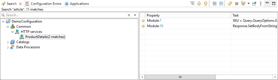
Information Structure
At the first level of hierarchy are projects. Within a project, there is a configuration tree that contains only those elements, along with their parent elements, where the search string was found.
You can display search results as a flat list. To do this, click ![]() (Show Menu), then select Show as List.
(Show Menu), then select Show as List.
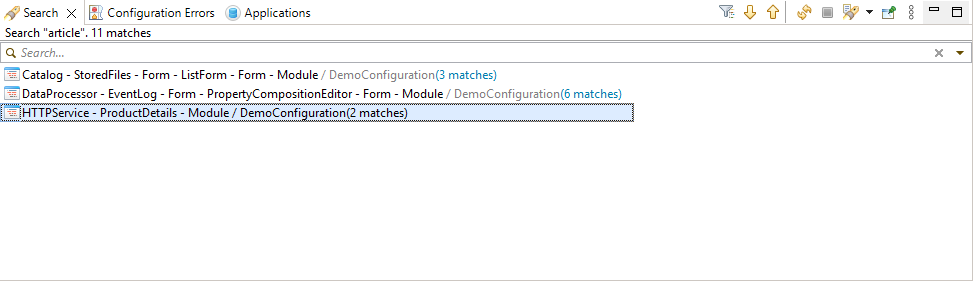
Legend
Projects and configuration elements are marked the same way as in the Navigator panel, except for additional labels related to support, configuration validation, and Git integration.
Mouse Actions
Double-clicking on a found element opens the module in the 1C:Enterprise Language Editor and positions it on the found line if it is a module. If it is a configuration element, it opens the editor for that object.
Searching Within Search Results
The panel contains a search field that allows you to quickly find only the references you need. For example, only references located in modules (more details).
Filtering Results by Subsystems
When searching for references to an object, you can filter the results to show only those that belong to a specific subsystem in the configuration. There is a command in the panel for this action: (By Subsystems).
Command Bar
- (By Subsystems) opens a dialog that allows displaying only those configuration objects belonging to specific subsystems in the panel. If such a filter is already applied, the same dialog allows modifying or removing it entirely (see 1C:Enterprise documentation).
-
 (Show Next Match) highlights the next found element in the list and opens it in the relevant editor. If it is a module, it positions on the found line.
 -
 (Show Previous Match) highlights the previous found element in the list and opens it in the relevant editor. If it is a module, it positions on the found line.
 -
(Refresh) Updates the information in the panel.
-
 (Cancel Current Search) interrupts the search operation.
 -
 (Show Previous Searches) the drop-down list displays the search history. The current search is marked with a dot
  . Clicking any other search from the list displays its results in the panel. The History... command allows deleting unnecessary searches and setting the number of stored searches. The Clear History command clears this list and the panel Search.
 -
 (Pin Panel) If this button is pressed, the panel will not be closed by other panels in its group.
 -
(Show Menu) Opens a drop-down menu containing additional commands for the panel.
-
Show as List search results are displayed as a flat list, showing only the found elements.
-
Show as Tree search results are displayed as a hierarchical list, grouping found elements by their configuration structure and project association.
Context Menu
- Show in Panel submenu contains the following commands:
-
Explorer shows the directory containing the project files in the operating system’s file explorer.
-
Properties opens project properties in the Properties panel.
-
Next Match highlights the next found element in the list and opens it in the relevant editor. If it is a module, it positions on the found line.
-
Previous Match highlights the previous found element in the list and opens it in the relevant editor. If it is a module, it positions on the found line.
Start Page Workspace Editor
The start page is one of the client application windows. It always opens when the application starts, serving as the user's entry point.
The workspace is a part of the start page where forms placed on the page are displayed. For example, the workspace can display two forms: a report form on the left and a specialized catalog form on the right.
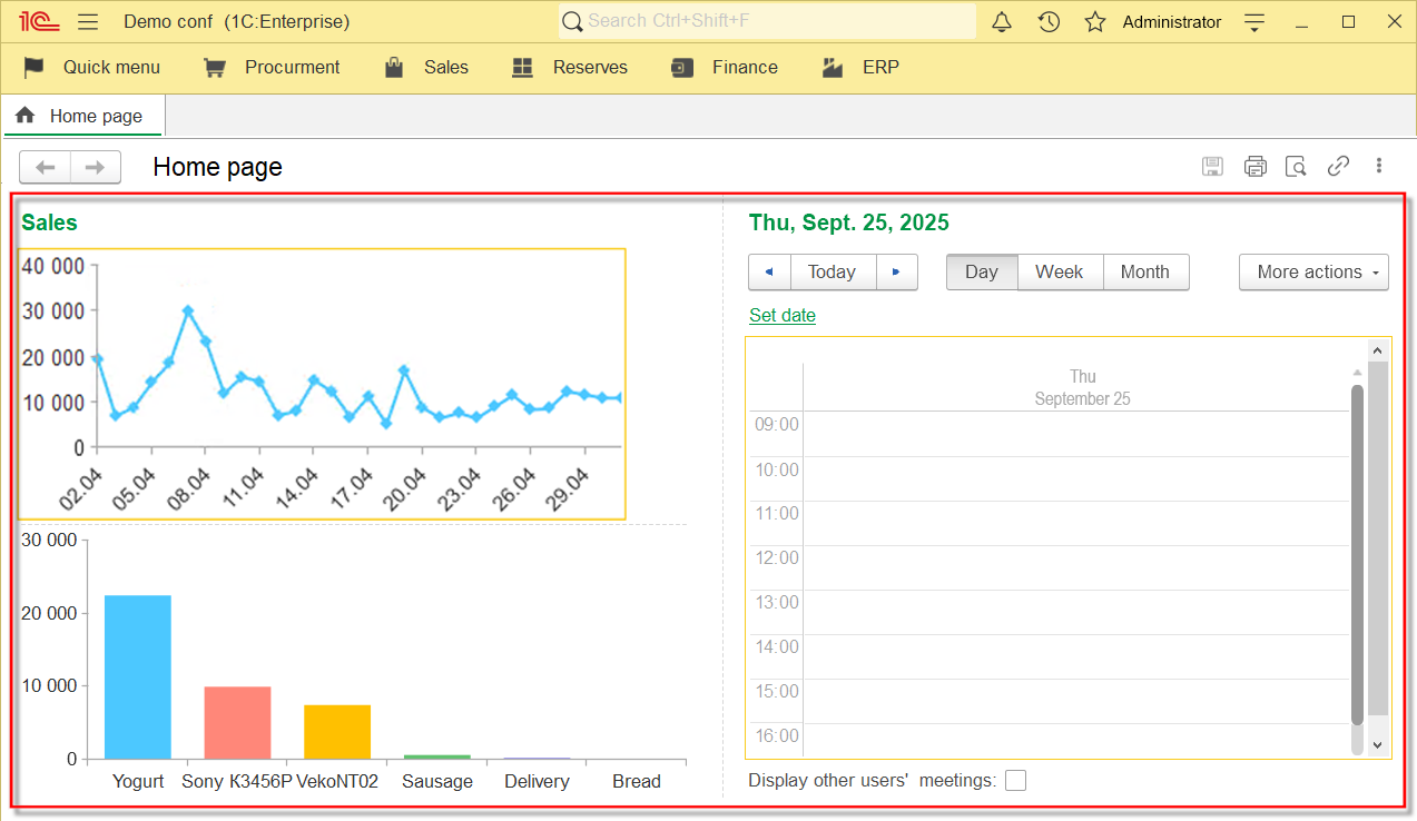
The Start Page Workspace Editor allows you to configure the composition and arrangement of applied object forms on the application's start page.
Opening the Start Page Workspace Editor
In the Navigator panel, click Open Start Page Workspace in the context menu of the configuration.
The functionality of this editor is similar to the start page workspace editor in 1C:Enterprise Designer, see Configuring the Start Page Workspace.
Editing the Command Interface
Editing command interfaces for different parts of the application is done in a single window within a unified editor. This simplifies development since the editor serves as a single point for managing and configuring the entire interface.
A consistent approach to displaying and editing commands also reduces the number of potential errors.
Command Interface Editor
The Command Interface Editor allows you to modify the set of commands in all application sections, including the entire application (Sections Panel), the main section (Main), and any subsystem.
The left pane of the editor (Sections) is used to select the desired section, while the right pane (Section Commands) allows you to manage the order of sections and command visibility.
Open the Command Interface Editor
To open the command interface editor, go to the Navigator panel and select Open Command Interface
-
either in the context menu of configuration
-
or any subsystem.
Configure Section Visibility by Roles
Section visibility by roles can be configured in the Section Commands window. This window contains subsystems that represent application sections. Each section can be assigned a default visibility setting, which is indicated in the Visibility column. This setting applies to all roles that do not have a personalized visibility setting enabled, meaning the checkbox is in its third state.
Additionally, each role can have its own personalized visibility setting for the section. If personalized visibility is set (whether the checkbox is checked or unchecked), it takes precedence over the default visibility setting.
Roles can be added by clicking Add Visibility for Role in the command bar.
Adjust Section Order
The order of sections in the application interface can be adjusted in the Sections window. To move sections, use the Move Up or Move Down option in the command bar.
Add a Section
If the existing sections are insufficient, a new subsystem can be created by selecting Add Section in the context menu of the Sections window.
This editor is similar in structure, appearance, and functionality to the three editors available in 1C:Enterprise Designer:
Configuration Command Interface
The configuration command interface consists of sections that are typically displayed at the top of the application in the sections panel. It is possible to manage the visibility and order of these sections.
Open the Configuration Command Interface
- To open the main section command interface, open the command interface editor.
- Select the top row Command Interface in the Sections window.
Main Section Command Interface
The main section command interface consists of commands available in the Main section. The visibility and order of these commands can be managed.
Open the Main Section Command Interface
- To open the main section command interface, open the command interface editor.
- Select Main Section in the Sections window.
Section Command Interfaces
Each section is represented by a top-level subsystem. The section command interface consists of commands available in that section (subsystem). The visibility and order of the section commands can be managed.
Open a Section Command Interface
- To open the main section command interface, open the command interface editor.
- Select the required subsystem in the Sections window.
Client Application Interface Editor
The client application interface is a set of standard panels that you can arrange on the screen in a specific way. For example, these include the section panel, the function panel of the current section, favorites, the open items panel, etc.
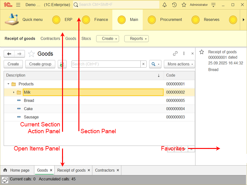
Open the Client Application Interface Editor
In the Navigator panel, click Open Client Application Interface in the context menu of the configuration.
Adding a Panel to the Interface
Panels available for placement are located at the bottom of the editor, highlighted with a gray background. Drag one of the available panels into an empty area marked with a dashed line.
Moving a Panel
Drag one of the panels already placed in the interface to an empty area marked with a dashed line.
Aligning in a Single Row
Drag one of the panels already placed in the interface to the beginning or end of another panel in the interface. 1C:EDT highlights the panel's vertical boundary and places the new panel next to the existing one.
Removing a Panel from the Interface
Drag one of the panels already placed in the interface to the bottom of the editor, highlighted with a gray background.
The functionality of this editor is similar to the client application interface editor in 1C:Enterprise Designer, see Configuring the Main Application Window - Customizing Panels.
Form Editor
The Form Editor allows you to create and modify forms.
Open the Form Editor
There are several ways to open the Form Editor:
- 1st method: In the Navigator panel, double-click the desired form.
- 2nd method: In the Navigator panel, use one of the available Open Default Form ... commands in the context menu of the configuration object to which the form belongs.
- 3rd method:
- Select the configuration object to which the form belongs in the Navigator panel.
- In the Properties panel, click the magnifying glass
 in one of the Default Form ... fields.
- 4th method:
- Select the desired common form in the Navigator panel.
- In the Properties panel, click Form - Open.
At the bottom of the editor, there are two tabs. On the Form tab, you can edit the structure of form items, and on the Module tab, you can edit the form’s module.
In terms of structure, appearance, and principles of operation, this editor is similar to the Form Editor available in 1C:Enterprise Designer—see Form Editor.
Editing Permissions
Several concepts and approaches are used in 1C:EDT to display and edit permissions.
More details on roles and access rights can be found in 1C:Enterprise documentation.
Editing by Task
Permissions can be edited in different editors. There are three editors in total. Which editor to choose depends on the task you are solving.
Assigning permissions always involves three entities:
-
A configuration object, which is the data being accessed.
-
A role, which defines who will perform actions.
-
A permission, which specifies what actions are allowed.
You must first decide which of these entities is the main driver of your actions.
-
If your goal is to protect data (configuration object), use the Configuration Object Permissions Editor.
-
If you need to define rules of behavior for a group of users (role), use the Role Permissions Editor.
-
In other cases, you may find it more convenient to edit permissions using the Editor All Roles.
Unified Tabular Representation
All three available editors display the involved entities in the same structured manner. Permissions are represented in a table, where columns list the actions that can be allowed or restricted. Rows display objects that either receive these permissions or are subject to them.
For the Configuration Object Permissions Editor, the rows contain roles because the task is to grant or restrict permissions for specific users.
Additionally, the configuration object itself is displayed in the rows, as permissions need to be set for its components, such as attributes and commands.
For the Role Permissions Editor, the rows contain configuration objects because the task is to grant or restrict access to certain objects.
For the Editor All Roles, both types of entities appear in the rows. Each configuration object appears as many times as there are roles that configure access to it.
Displaying Only Some Roles
The Configuration Object Permissions Editor and the Editor All Roles do not show all roles but only those that have permissions assigned. Roles without any permissions (where no checkboxes are selected) are not displayed. To assign permissions to roles that are not displayed, they must be added to the editor.
These editors also highlight in green those roles that have the property Set Permissions for New Objects enabled.
Displaying Only Some Objects
The role permissions editor, like other editors, also does not display all configuration objects but only those for which some permissions have been set. If no permissions are set for a configuration object, it is not shown in the editor. To set permissions for objects that are not displayed, they need to be added to the editor.
Remove All Permissions
If, while editing permissions in any editor, you remove all permissions in a row, including subordinate elements, then the next time you open the permissions editor, such rows will no longer be displayed in the table.
It is possible to remove all permissions and immediately hide the row from the editor. To do this, click  in the command bar.
Set Permissions for a Role or Object That Has No Permissions
If no permissions are set for a role, that role does not appear in the permissions editors. Similarly, if no permissions are set for a configuration object, that object does not appear in the role permissions editor.
To set permissions for such a role or configuration object, click  in the command bar and select the required object or role. Permissions can be set immediately upon selection or later after the role or object appears in the editor.
All Roles Editor
The All Roles editor allows you to view and edit all permissions for all roles on all configuration objects.
Open the All Roles Editor
In the Navigator panel, click All Roles:
-
Either in the context menu of configuration
-
Or in the context menu of the Roles branch.
The table displays all roles that have permissions. Roles without any permissions (where no checkboxes are selected) are not displayed.
Roles with the property Set Permissions for New Objects enabled are marked in green.
Role Permissions Editor
The role permissions editor allows you to view and edit all permissions for a role on configuration objects.
Open the Role Permissions Editor
You can open the editor in several ways:
- Method 1:
-
In the Navigator panel, double-click the required role.
-
Click the Permissions tab.
- Method 2:
-
In the Navigator panel, select the required role.
-
In the Properties panel, click Permissions - Open.
The table displays all configuration objects for which this role has permissions.
Configuration Object Permissions Editor
The configuration object permissions editor allows you to view and edit all role permissions for a given configuration object.
Open the Configuration Object Permissions Editor
1. In the Navigator panel, double-click the required configuration object.
- Click the Permissions tab.
The table displays all roles that have permissions for this object. Roles without any permissions (where no checkboxes are selected) are not displayed.
Roles with the property Set Permissions for New Objects enabled are marked in green.
Permissions Parameter Group
The Permissions parameter group allows you to change the way permissions are displayed in the permissions editors.
Open the Permissions Parameter Group
Click Window > Preferences... > V8 > Permissions.
Comparison and Merging of Configurations
Compare And Merge Projects
To compare and merge two projects, follow these steps in the Navigator panel.
-
Select the projects you want to compare.
-
Click Compare/Merge in the context menu of one of the selected projects.
Field Descriptions
-
Main Source is the project in the Navigator panel or the file system that will be compared.
-
Other Source is the project in the Navigator panel or the file system that will be compared with the main source.
Fastpath: If you hover over the group frame, you can drag the source with the mouse to swap it with another source.
-
Common Ancestor is the project that serves as the ancestor of the main and other sources.
-
Use Common Ancestor means checking this box will enable a three-way comparison using the common ancestor. Select the ancestor in the Common Ancestor field.
-
Allow Deletion Of Main Source Objects means checking this box will allow deletion of objects in the main source. The 1C:Enterprise platform automatically allows this action only when updating the vendor configuration. Since you are manually selecting projects for comparison and merging, you must decide whether to enable this option.
-
Compare Modules Considering Structure If this option is selected, 1C:Enterprise language modules are compared based on individual methods within the module. Otherwise, modules are compared as a single text block.
-
Matching Strategy This determines how objects in the merged and current configurations are matched. This method is used when there are conflicting changes that need to be resolved manually in the Compare and Merge Configurations Editor:
-
By UUID Matches objects by their internal configuration object identifier.
-
By Name Matches objects by their configuration object name.
-
By UUID, then by Name First, it searches for a configuration object with the same internal identifier. If none is found, it searches for a configuration object with the same name.
-
External Merge Settings This specifies the path to the file containing previously saved configuration merge settings from the Compare and Merge Configurations Editor.
Compare And Merge Objects
To compare and merge two objects, follow these steps in the Navigator panel.
-
Select the objects you want to compare.
-
Click Compare/Merge in the context menu of one of the selected objects.
Field Descriptions
-
Main Source is the object that will be compared.
-
Other Source is the object that will be compared with the main source.
Fastpath: To swap the objects, select another object from the drop-down list in either source.
-
Matching Strategy This determines how objects in the merged and current configurations are matched. This method is used when there are conflicting changes that need to be resolved manually in the Compare and Merge Configurations Editor:
-
By UUID Matches objects by their internal configuration object identifier.
-
By Name Matches objects by their configuration object name.
-
By UUID, then by Name First, it searches for a configuration object with the same internal identifier. If none is found, it searches for a configuration object with the same name.
-
Compare Modules Considering Structure If this option is selected, 1C:Enterprise language modules are compared based on individual methods within the module. Otherwise, modules are compared as a single text block.
-
External Merge Settings This specifies the path to the file containing previously saved configuration merge settings from the Compare and Merge Configurations Editor.
Automatic Configuration Merge Settings
The configuration comparison and merge operation can be initiated directly (for example, by clicking Compare/Merge in the project’s context menu) or indirectly when merging Git branches. If it is a three-way comparison without conflicting changes, 1C:EDT will merge the configurations automatically. Three-way comparison is often run in Git.
In all other cases, after comparison, 1C:EDT will automatically apply configuration merge settings and open the comparison and merge editor. This allows you to confirm or modify the automatically set merge settings.
This section describes the rules 1C:EDT follows when applying these settings.
Merge Settings
In the comparison and merge editor, 1C:EDT displays the configuration in a format similar to how it appears in the Navigator panel. The difference is that the tree in the editor is more detailed. For example, it includes all properties of objects that are typically displayed separately in the Properties panel within the Navigator panel (in the illustration, the Configuration node has a child node Properties).
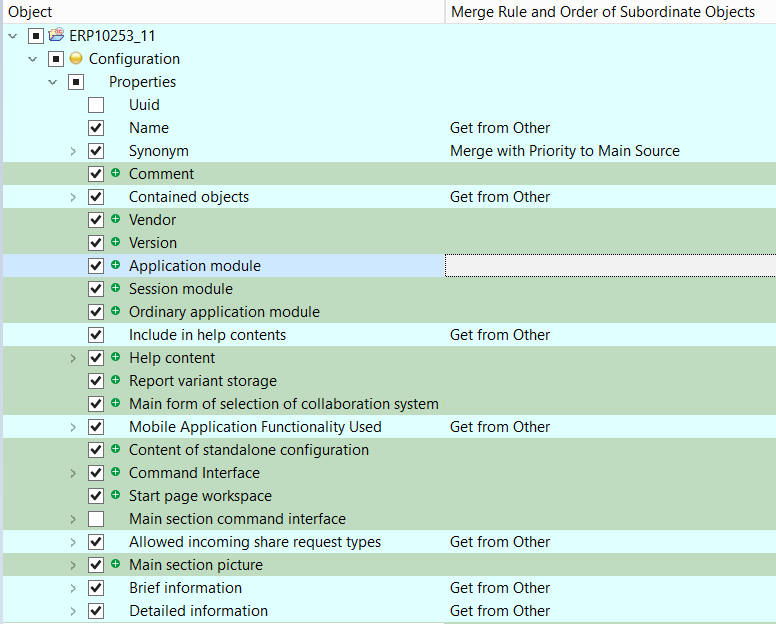
A merge setting consists of a checkbox (in the first column on the left) and a merge mode (in the last column). Each node in the tree (each row) has such a setting.
The checkbox appears for all nodes, but in some cases, it cannot be modified. For example, if the compared values are identical, the checkbox will be unchecked and cannot be enabled.
The merge mode is displayed only for nodes
-
that participate in the merge procedure,
-
support merge mode changes,
-
or have a merge mode other than Do Not Merge.
Merge Checkboxes
Each checkbox has three states.
-
 Checked. This means that the node and all its descendants will be included in the merge procedure according to their respective merge rules.
 -
 Unchecked. This means that the node and all its descendants will not be included in the merge procedure and will remain unchanged.
 -
 Partially Checked. Indicates that some descendants have checked boxes, while others do not. Nodes with checked boxes will be included in the merge procedure, while unchecked ones will remain unchanged.
The Partially Checked state is possible only for nodes with descendants. It is set automatically and cannot be manually enabled by clicking the checkbox.
Clicking a Partially Checked checkbox will change it to the Unchecked state.
When a checkbox is checked or unchecked, all child nodes will also be checked or unchecked accordingly. The parent nodes will be updated to reflect the status of their child nodes.
Merge Modes
There are four merge modes.
-
Do Not Merge. Selecting this mode disables the merge checkbox. This means that the node and all its descendants will not be included in the merge procedure.
-
Get from Other. The value from the other source will be used during the merge. If this mode is selected for a parent node, checkboxes for its child nodes can be enabled or disabled to exclude or include them in the merge procedure.
-
Merge with Priority to Other Source. This mode is used in three-way comparison to determine how conflicting changes should be processed. Non-conflicting changes will be merged, while for conflicting changes, the value from the other source will be used. If this mode is selected for a parent node, modifying checkboxes for its child nodes will not be possible.
-
Merge with Priority to Main Source. This mode behaves similarly to the previous one, except that conflicting changes will not be included in the merge.
Merge Configuration Rules
In simple terms, for two-way comparison, merge checkboxes are set to transfer all changes into the main source. For three-way comparison, additional logic prevents checkboxes from being set when changes exist only in the main source, ensuring they are not unintentionally erased.
In most cases, your task will not be to enable checkboxes where they are missing, but to review conflicting module changes and disable checkboxes for nodes that should not be transferred to the main source.
1C:EDT automatically sets checkboxes to the cleared state and prevents modifications in the following cases.
-
When values in the main and other sources are identical (no changes to apply).
-
When modifying the configuration object in the main source is restricted by configuration support rules (modifications are not allowed).
-
When the configuration object exists only in the main source and the following conditions apply (deletion is not allowed).
-
A two-way comparison runs.
-
The Allow Deletion of Main Source Objects checkbox was disabled in the comparison dialog.
If none of these rules apply, 1C:EDT proceeds as follows.
-
If the configuration object exists only in the other source, the checkbox is enabled
, and the merge mode is set to Get from Other (new object should be added). -
If the configuration object exists only in the main source, the checkbox is cleared
, and the merge mode is set to Do Not Merge (removal from the main source is allowed but must be explicitly included in the merge procedure manually). -
If a two-way comparison runs and values in the main and other sources differ, the checkbox is enabled
, and the merge mode is set to Get from Other (existing object should be updated). -
If a three-way comparison runs.
-
And there is a conflicting change: both the main and other sources have different modifications from the common ancestor. The checkbox is cleared
, and the merge mode is set to Do Not Merge. -
And the value in the other source does not differ from the common ancestor, the checkbox is cleared
, and the merge mode is set to Do Not Merge (either merging is unnecessary because the main source also matches the common ancestor, or changes in the main source need to be preserved without being overwritten).
There is an exception related to support settings. If there are conflicting changes in support settings during configuration merging, they are always merged using the Get from Other mode.
Module Comparison Considering the 1C:Enterprise Language Semantics
When comparing different modules or different versions of the same module, the built-in file comparison mechanism is used.
It considers the semantics of the 1C:Enterprise language and can detect relocated code fragments (procedures and functions) within a module. As a result, you do not just see that the lines of one module differ from another, but you can also understand that the module itself has not fundamentally changed. Only the placement of procedures within it has been altered.
 (Show Moved Blocks / Hide Moved Blocks)
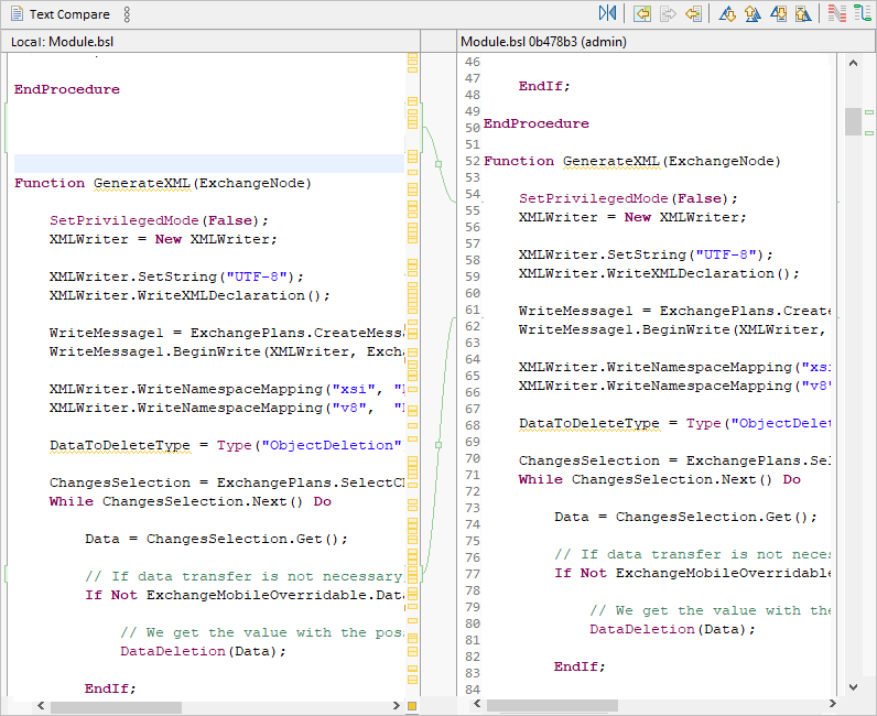
You can also group adjacent modified lines into a single block. This makes it easier to analyze changes in these lines.
 (Group Diffs / Ungroup Diffs)
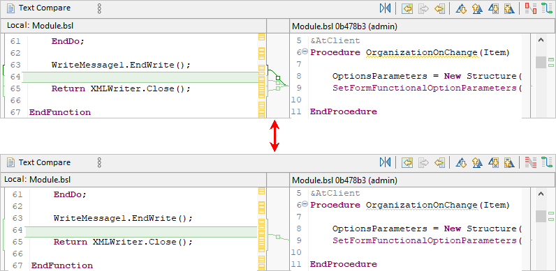
Module Comparison and Merging Based on Structure
To compare and merge modules while considering their structure, enable the Compare Modules Based on Structure checkbox in 1C:EDT preferences.
This mode allows you to analyze differences at the level of individual module methods. When comparing configurations, methods are displayed within the overall configuration structure. For example, you can see added methods and exclude any of them from the merge.
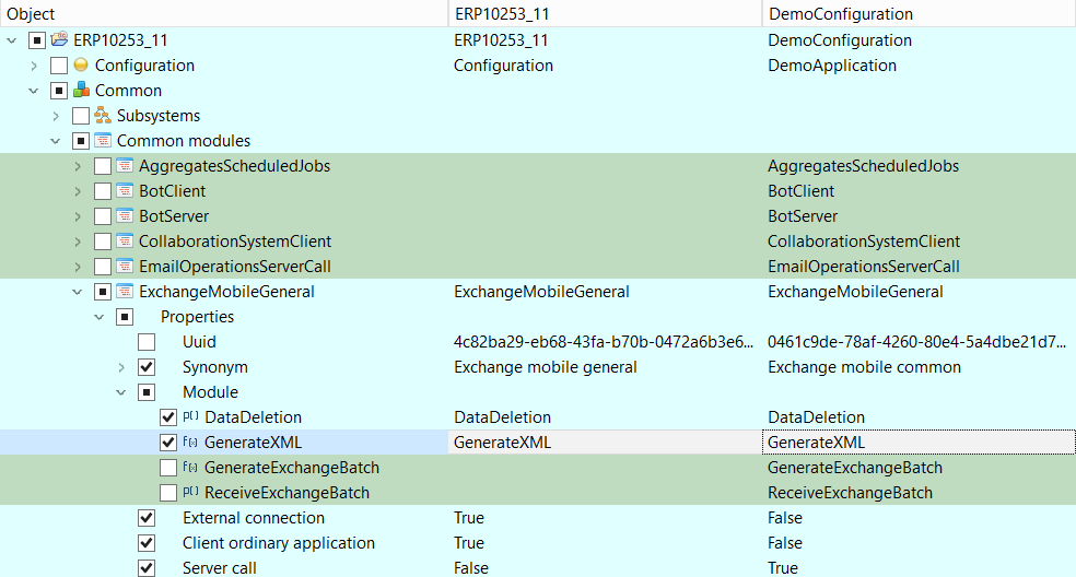
When comparing modules, the upper section of the comparison and merge editor displays the list of methods, while the lower section compares only the selected method.
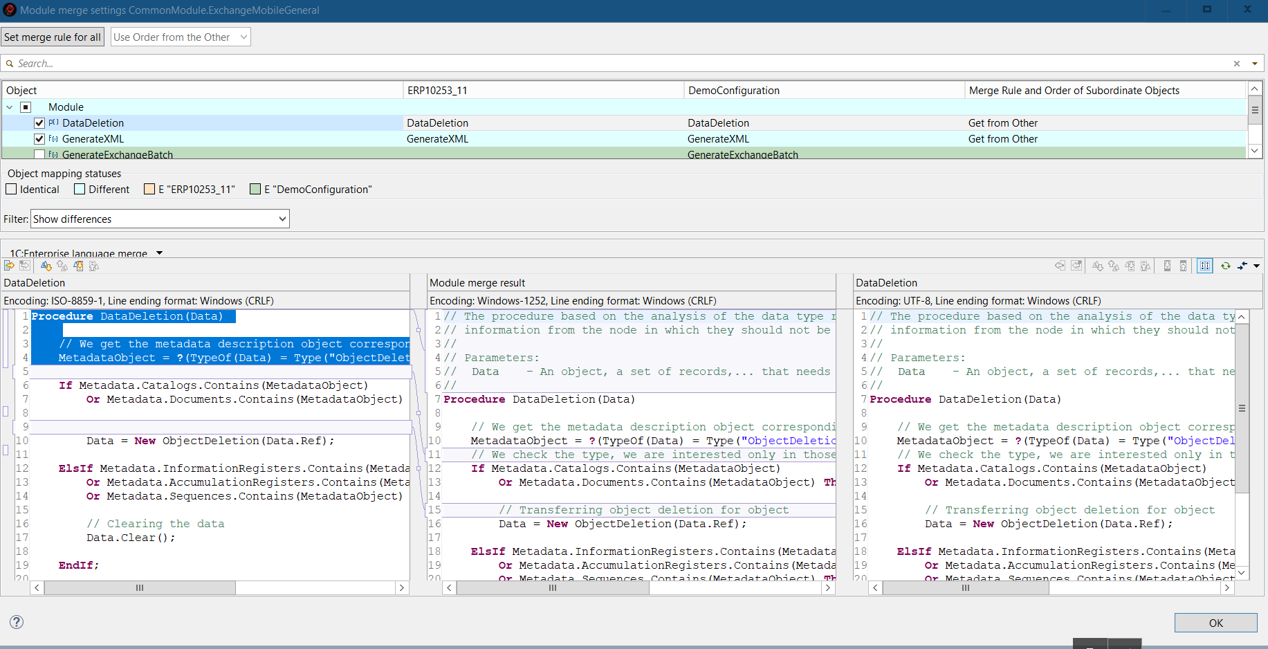
In this mode, 1C:EDT first parses the module's contents before performing the comparison. If the module parsing fails (for example, due to a syntax error), the module will be compared as plain text without considering its structure.
Module Comparison and Merging Using External Tools
To compare and merge modules using external tools, specify the path to the executable file of the external tool and the operations for which it should be used in 1C:EDT preferences.
If you want the Compare and Merge Configurations Editor to automatically apply external tools for all modules, also enable the Automatically Merge Using Selected Tools checkbox in 1C:EDT preferences. Otherwise, you will need to manually select this mode for the modules you want.
You can also choose which nodes to merge using an external tool: All or Only Double-Modified, meaning nodes with conflicting changes.
Additionally, you can specify a timeout for executing the external program, after which it will be terminated.
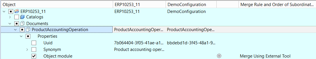
Before performing a merge, you can analyze certain modules. To do this, click Compare Using External Tool in the module's context menu.
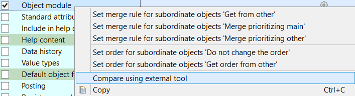
This command allows you to compare module texts across sources.
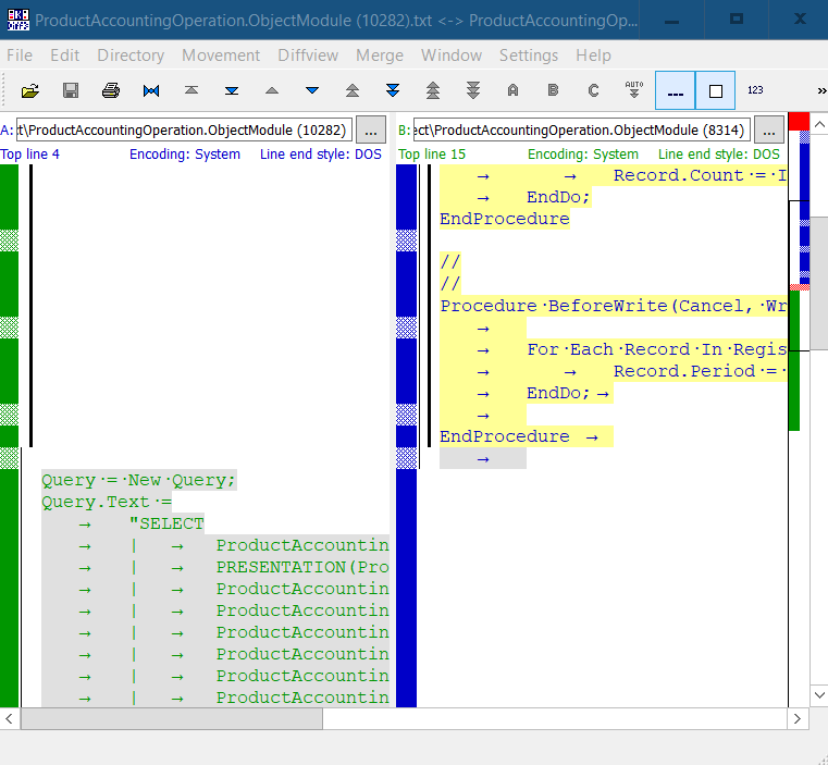
Clicking the gear icon in the module row launches the external tool for merging the modules.
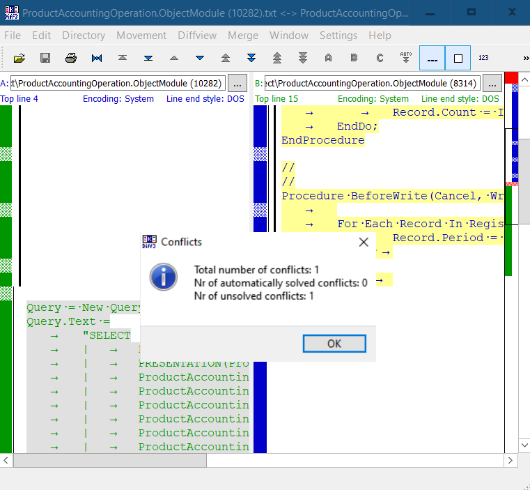
The merge result is saved in the editor, and the merge rule is set to Manual Merge.
If individual module merging is not required, you can directly start the merge procedure. In this case, the external program will first merge the nodes where the Merge Using External Tool mode is enabled. After that, the main update will be run.
If you do not accept the merge result from the external tool for some nodes, the comparison and merge editor will reopen, displaying a gear icon with an exclamation mark next to those nodes.
Compare and Merge Configurations Editor
This editor allows you to view differences between configurations, mark objects and properties that should (or should not) be transferred to the main configuration, and merge two configurations. From this editor, you can also open the text file comparison and merge editor (more details), which allows you to compare individual modules and edit the resulting text before merging two modules.
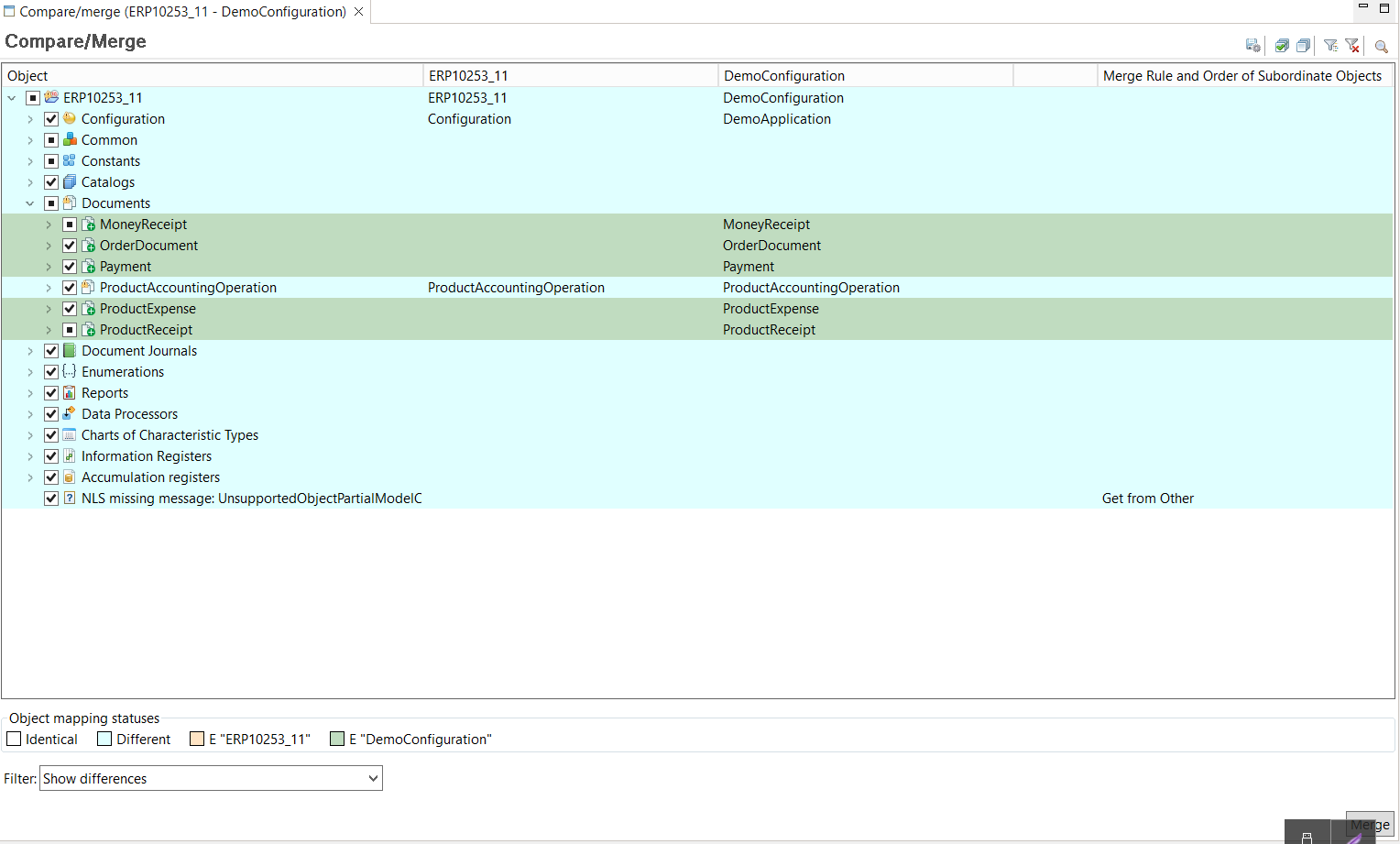
Legend
-  : Merge checkbox enabled. Indicates that the node and all its descendants will participate in the merge procedure according to their respective merge rules.
-
: Merge checkbox disabled. Indicates that the node and all its descendants will not participate in the merge procedure and will remain unchanged.
-
: Merge checkbox partially enabled. Indicates that some descendants have checked boxes, while others do not. Nodes with checked boxes will be included in the merge procedure, while unchecked ones will remain unchanged.
Export Merge Settings
A merge setting consists of a checkbox (in the first column on the left) and a merge mode (in the last column). Each node in the tree (each row) has such a setting. Once you have set the checkboxes and merge modes as needed, you can save these settings to a file to use them automatically next time.
To do this, press ![]() (Export Comparison Settings) in the editor's command bar.
(Export Comparison Settings) in the editor's command bar.
Compare And Merge Modules Editor
The Compare and Merge Text Files Editor allows you to compare the contents of two modules and merge them.
The editor consists of three areas. On the left is the main source, on the right is the other source, and in the middle is the merge result.
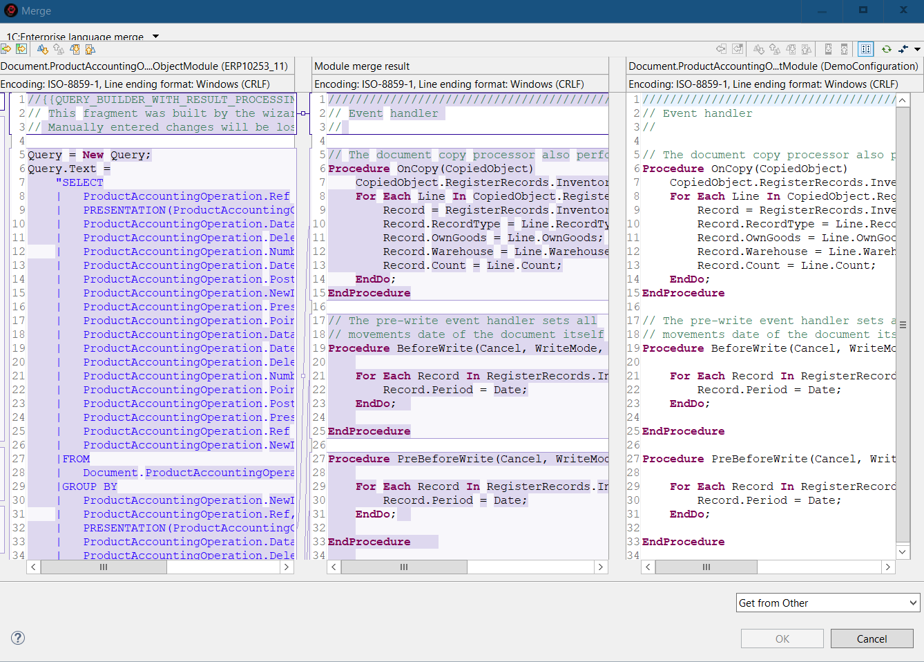
This editor is used for comparing and merging modules that are included in the Compare and Merge Configurations Editor. To open this editor, click the "gear" icon in the Module row.
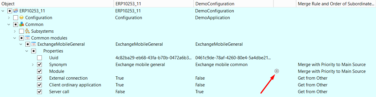
The Compare and Merge Text Files Editor can be used, for example, to compare two common modules. It is also integrated into the Compare and Merge Configurations Editor, so when comparing modules, this editor will also be used.
Different comparison and merge strategies can be selected. This set of strategies is expandable, so you can implement your own strategy if needed.
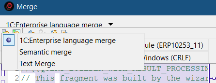
While analyzing changes, you can navigate through change blocks, manually transfer changes from the left or right to the result, and edit the result manually.
Any two areas can be compared in an individual dialog.
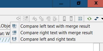
Synchronous scrolling of all three areas can be enabled or disabled—both horizontally and vertically.
File Comparison Panel
The File Comparison Panel allows you to compare the text content of two files.
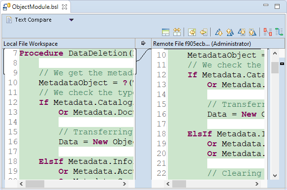
It can be opened when synchronizing a local and remote repository to view differences in modules. It can also be opened to view differences between different versions of a module in a local repository.
Additionally, it can be used to compare the contents of metadata files and other objects stored in XML format.
This panel includes the built-in file comparison mechanism of 1C:EDT. Its advantage is that it accounts for semantics and can detect code fragment movements (procedures and functions). For example, you can enable the option to show order changes  , making it visible that the procedure OnCreateAtServer() has changed its location in the module.
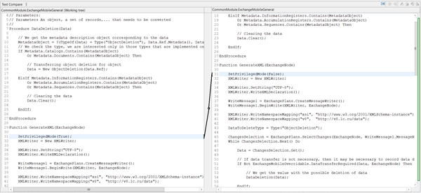
Furthermore, it is possible to group matching lines  , which makes it easier to perceive changes across several adjacent lines: without grouping (top figure) and with grouping (bottom figure).
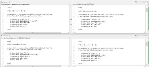
Compare and Merge Parameter Group
The Compare and Merge parameter group allows you to select the method for comparing modules: with structure consideration or without.
Open Compare and Merge parameter group
Click Window > Preferences... > V8 > Compare and Merge.
External Tools parameter group
The External Tools parameter group allows you to configure which external tools and how they will be used for module comparison.
Open The External Tools parameter group
Click Window > Preferences... > V8 > Compare and Merge > External Tools.
Using ER Diagrams
An ER diagram, like the configuration object tree, is designed to present the entire application. However, it uses a different visualization model in which data structures are represented as an entity-relationship diagram (ER diagram).
The need for this data model is directly related to the growth of the platform and the significant complexity of applications. If you look at any 1C:Enterprise database, you will see that it is based on the relational model. It consists of tables that are interconnected in various ways. Tables have fields, and these fields form keys that allow linking tables together.
This model is convenient for computer processing but not for visual representation. It is particularly inconvenient in 1C:Enterprise applications, where most tables have concrete applied meanings rather than abstract ones.
For this reason, 1C:Enterprise Designer `historically` uses a different conceptual model that represents the database as a configuration object tree. Configuration objects conceal the relational model behind them and are grouped according to their classification in applied tasks. This representation is useful for quickly locating the required objects and modifying their properties. However, it does not provide a simple and clear understanding of the interconnections between different objects.
Modern applied solutions contain a large number of configuration objects, sometimes exceeding 10,000. At such a scale, identifying relationships between objects using existing tools becomes labor-intensive. Moreover, the effort increases not only due to the direct rise in the time it takes to search for references among a large number of objects but also because the identified relationships need to be remembered and visualized. If there are many such relationships, selecting an appropriate external tool becomes a challenge.
The use of the entity-relationship model (ER model) effectively solves this problem. An ER model represents any data structure as a set of entities with attributes. These entities interact with each other through relationships.
In 1C:Enterprise terms, an entity is a configuration object, and an attribute is a broad concept covering configuration object attributes, dimensions, resources, and so on. Thus, the ER model of a 1C:Enterprise database is an unstructured collection of configuration objects, including their attributes, with certain interconnections. An ER diagram is a tool that enables the visualization of this model.
It is important to understand that an ER diagram is not just an optional or additional feature. It is an independent tool for modeling the subject area, with its own advantages and characteristics. It is not an equivalent or a replacement for the configuration object tree. It is another development tool that serves its own audience.
The configuration object tree is more convenient for developers who are deeply immersed in the application or familiar with its history. It allows for quick modifications to the application, as developers generally know the relationships between objects and keep them in memory.
Unlike the configuration object tree, the ER diagram is geared toward developers who are not deeply familiar with an applied solution but need to quickly understand the structure of a particular part of it. It is also useful for documenting developed mechanisms, including by the developers themselves, as it clearly displays relationships between objects or groups of objects.
ER Diagram Perspective
The ER Diagram perspective is a workspace for creating and editing ER diagram files.
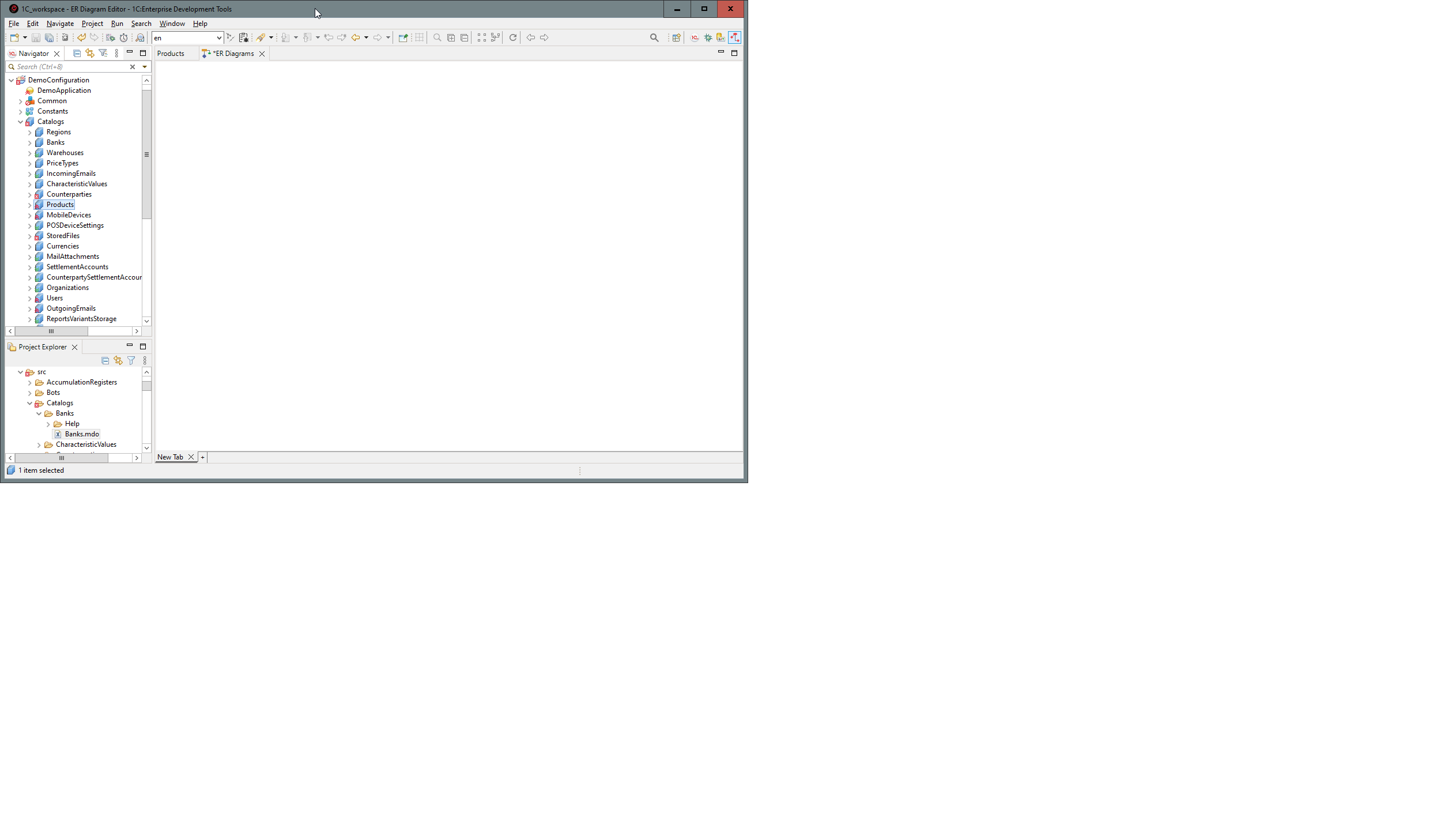
Open the ER Diagram Perspective
The ER Diagram perspective can be opened in several ways.
-
From the perspective panel, click
(Open Perspective) ER Diagram. -
From the main menu of the main window, click Window > Perspective > Open Perspective > Other... > ER Diagram.
The default composition of the ER Diagram perspective includes the following elements.
-
Navigator Panel. This panel displays a list of applications and their elements developed using 1C:EDT, including configuration projects, configuration extension projects, as well as external report and data processor projects.
-
Editor Area This area automatically opens the ER Diagram Editor, displaying a new ER diagram file.
-
Panels.
-
ER Diagram. This panel displays the part of the ER diagram currently shown in the editor window.
-
Project Structure. This panel displays the application structure as a collection of standard files rather than as a tree of configuration objects.
ER Diagram Editor
The ER Diagram Editor allows you to edit ER diagrams.
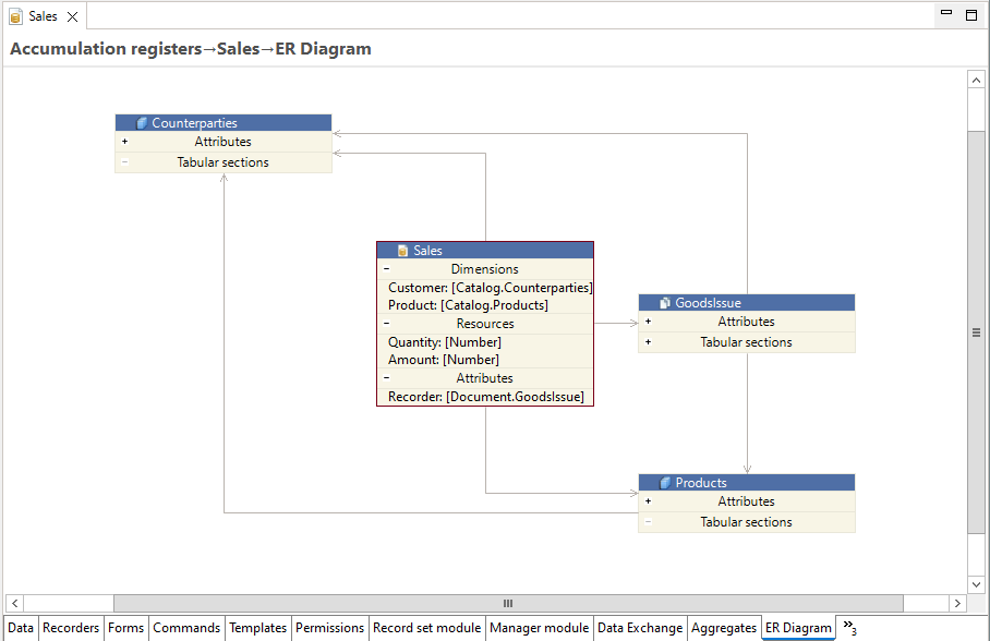
A new window of this editor opens when you open the ER Diagram perspective.
This editor is located on the ER Diagram tab of the configuration object editor.
This editor also opens when you double-click on an ER diagram file in the Project Structure panel.
Which Configuration Objects This Object Uses
For example, there is a register Sales in the configuration. You need to find out which configuration objects this register uses, meaning which configuration objects its attributes, dimensions, and resources refer to.
-
Open the editor for the Sales register.
-
Go to the ER Diagram tab in the editor. On this tab, you will see the objects that this register uses.
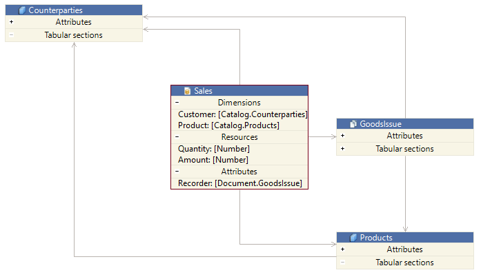
On this ER diagram, you can see that the Sales register uses the GoodsIssue document and the Products and Counterparties catalogs. These links originate from the register. Additionally, the ER diagram shows mutual relationships between the used objects themselves (between the document and the catalogs).
An ER diagram that opens on the configuration object editor tab can be modified and adjusted: expanding attribute groups, dragging objects to arrange them more conveniently, and so on. But keep in mind that these changes are not saved in the configuration. The displayed ER diagram can be saved as a picture or printed, either in full or partially. However, the next time you open the configuration object editor and go to the ER Diagram tab, the ER diagram will be redrawn in its default format.
If you want to edit and save the ER diagram, use the Documentation scenario.
How a Mechanism or Subsystem Is Structured
Suppose you need to understand the structure of an unfamiliar mechanism or subsystem. For example, you need to see how the Inventory subsystem is structured, which objects it includes, and how they are interconnected.
-
Open the Inventory subsystem editor.
-
Go to the ER Diagram tab in the editor. There, you will see the objects used by this subsystem.
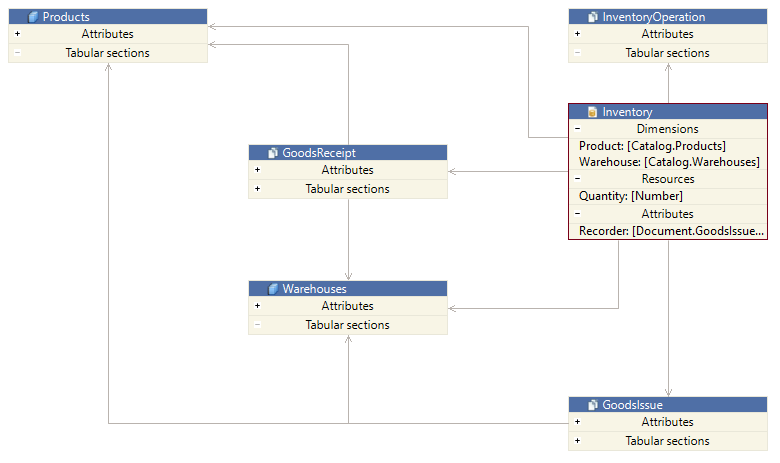
Besides configuration objects, this ER diagram also displays subordinate subsystems. Subsystems are groups of objects. Objects within them have connections to objects outside of the subsystem.
To view the structure of any of these subsystems, such as the Characteristics subsystem, double-click on it directly within the ER diagram. You will then see its structure.
To return to the previous ER diagram, click Back to Upper Group in the Main Window Command Bar.
Documenting a Mechanism Using an ER Diagram
Suppose you need to document a particular configuration mechanism. This could be done while developing it or afterward, when it has already been completed by someone else.
The key difference in this scenario is that interaction with the ER diagram takes place over an extended period. This means that the ER diagram should be saved in its current state so that you can continue editing it later.
In this case, you can create a separate ER diagram file and save it in your project. This can be done in two ways.
- Method 1:
-
Open the ER Diagram perspective.
-
Drag the necessary configuration objects from the Navigator panel into the ER diagram editor (more details).
-
Click
(Save) to save the ER diagram file.
- Method 2:
-
Click File > New > Other... > 1C:Enterprise Development Tool > ER Diagram.
-
Choose the project where the ER diagram file will be saved and specify the file name.
-
Click Finish. A new ER diagram file will open.
-
Drag the necessary configuration objects from the Navigator panel into it (more details).
-
Click
(Save) to save the ER diagram file.
To view the ER diagram file, go to the Project Structure panel.
Application Development
You can use the ER diagram during the development of an applied solution.
Click Open Object in the object's context menu to open the configuration object editor, where you can modify the object's properties.
Viewing an ER Diagram
View Object Attributes
To better understand which attributes of an object are involved in relationships, double-click on the Attributes row to expand it. Similarly, you can expand other attributes, such as tabular sections, dimensions, and resources, as well as collapse expanded groups.
If attribute names do not fit within the displayed area, you can resize the object by dragging its right or left border.
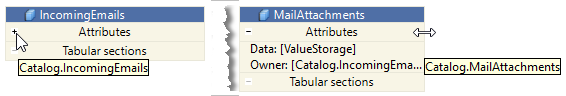
Highlight Outgoing Connections of an Object
An object may have multiple connections. To make navigation easier, click on the header of the object being examined, and all outgoing connections will be highlighted. Additionally, the object's attributes involved in these connections will also be highlighted.
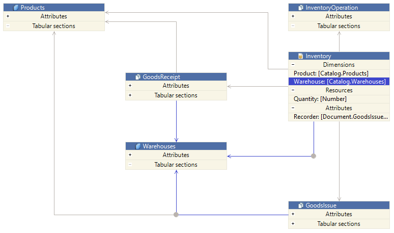
Highlight a Single Connection
If you are interested in only one specific connection, click on it to highlight the connection and the associated attribute.
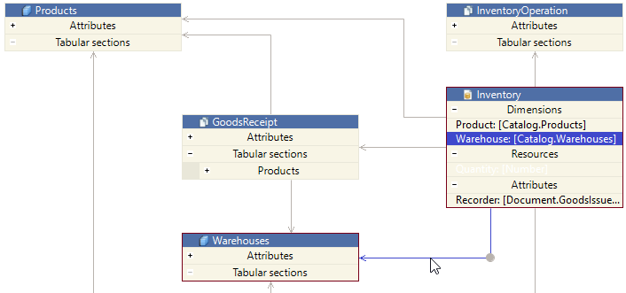
Navigating Embedded ER Diagrams
Subsystems are groups of objects. Objects within them have connections to objects outside of the subsystem. If you double-click on a subsystem, a new ER diagram will appear, displaying the structure of the selected subsystem.
The ER diagram supports forward and backward navigation similar to web browsers. After reviewing the structure of a subordinate subsystem, you can simply click Back to Upper Group in the Main Window Command Bar to return to the previous ER diagram.
To reopen the ER diagram of a subordinate object, click Forward to Inner Group in the Main Window Command Bar.
Viewing Large ER Diagrams
ER diagrams can be quite large. Navigating them often requires scrolling both vertically and horizontally. To avoid getting lost in large ER diagram, you can use the ER Diagram panel.
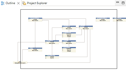
This panel marks the portion of the ER diagram currently visible on the screen. You can move around the ER diagram not only by scrolling but also by dragging the highlighted area in the ER Diagram panel.
Editing the ER Diagram
Add a New Object to the ER Diagram
To add a new object to the ER diagram, simply drag it from the Navigator panel into the ER diagram.
Add All Related Objects
For example, if the ER diagram contains the Users catalog, and you want to add all objects that reference this catalog,
click Add Referencing Entities in the object's context menu.
Add Objects Related to an Attribute
If you want to add objects related to a specific attribute to the diagram, click Add to ER Diagram in the attribute's context menu.
If the attribute is of a composite type, all objects included in its type will be added.
Align with Neighboring Objects
When moving objects, you can align them with neighboring objects using guidelines. Guidelines appear automatically.
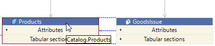
Automatically Arrange Elements on the Diagram
After editing, the diagram may become cluttered.
To make it easier to view, instead of manually moving objects with the mouse, click  (Auto Arrange) in the Main Window Command Bar. The diagram will rearrange the objects without changing their sizes.
Move a Connection Line
You can move connection lines by dragging them with the mouse.
Troubleshooting: The cursor does not change when hovering over a connection line. Do not wait—just drag the line immediately.
Bend a Line
Connection lines can be bent by adding bend points or straightened by removing them.
To bend a line, follow these steps:
-
Click Add Bend Point in the context menu of the line. Bend points will appear on the line.
-
Drag the bend points as needed.
To straighten a line, follow these steps:
-
Select the line by clicking on it. Bend points will appear on the line.
-
Click Remove Bend Point in the context menu of the unnecessary point.
Automatically Build Connections
If you're having trouble arranging the links manually, you can click  (Automatic Creation of Links) on the Main Window Command Bar. This command will rebuild the connections without changing the sizes or positions of objects.
Combine into Group
Sometimes, a group of objects in the ER diagram serves a common purpose, and the details of their internal interactions are not important. For example, suppose you have added objects that use the Regions catalog to the diagram.
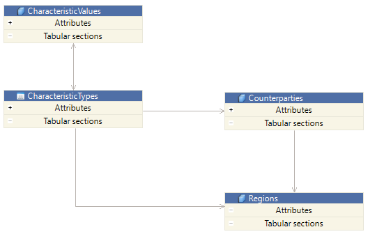
In addition to the Counterparties catalog, the chart of characteristic types and the information register also use it. However, these objects are not independent entities whose interactions matter in this diagram. They are part of the characteristics mechanism implemented in the application. Therefore, you can group them:
-
Click and drag the mouse, starting from an empty area of the diagram. The diagram will begin drawing a selection rectangle.
-
Cover the elements you want to group with this rectangle. They will be selected.
-
Click Group in the context menu of any selected object. Instead of these elements, the diagram will now show a group.
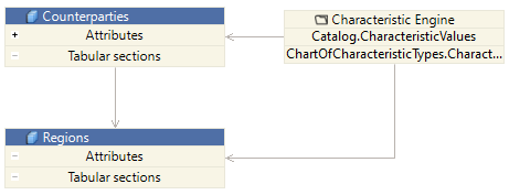
As a result, the diagram will appear more streamlined, showing that the Regions catalog is only used by the Counterparties catalog. However, like most objects in this application, it is also part of the characteristics mechanism. The details of this mechanism are not relevant in this case.
You can assign a custom name to the group that best reflects its purpose. To do this, click Rename in the context menu of the group.
Add, Remove, or Hide a Comment
You can add comments to diagram objects. For example, comments can be used for explanatory notes or reminders for further modifications of the ER diagram.
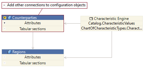
To add a comment, click Comment > Edit in the context menu of the object’s header.
To remove a comment:
-
Click Comment > Edit in the context menu of the object’s header.
-
Delete the comment text.
-
Click OK.
You can hide and show comments by clicking Comment > Hide and Comment > Show in the same menu.
Tip: When a comment is hidden, an icon in the object’s header indicates that a comment is associated with this object.
Customize Colors
If you do not like the default color scheme used in the ER diagram, you can change it.
In the Navigator panel, click Properties > V8 > ER Diagram > Colors in the project's context menu.
Here, you can choose one of the predefined themes for the ER diagram or set custom color preferences.
In the adjacent Line Styles parameter group, you can modify the style of the ER diagram lines.
Update the ER Diagram
If you are editing an ER diagram for a project that is still under development, it is important to keep it up to date with the latest project changes.
If objects included in the ER diagram have been modified, open the schema and click  (Refresh Tab) in the Main Window Command Bar. The ER diagram will be redrawn to reflect the current state of the configuration.
Save the ER Diagram
A modified ER diagram can be saved to any directory. To do this, click File > Save.
Copy the ER Diagram
An ER diagram that has not been modified can be copied to another directory. To do this, follow these steps:
-
Go to the Project Structure panel.
-
Click Copy in the context menu of the ER diagram file. The ER diagram will be copied to the clipboard.
-
Open the destination folder in File Explorer and paste the ER diagram file from the clipboard.
ER Diagram Panel and Data ER Diagram Editor
When the ER Diagram Editor is active, the ER Diagram panel displays the portion of the ER diagram currently visible in the editor window.
This panel makes it easier to interact with large ER diagrams that do not fit within the editor window. By moving the selection area in the panel, you can choose which part of the ER diagram is displayed in the editor.
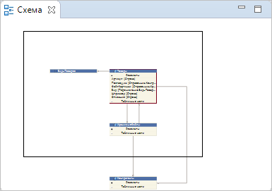
This panel is part of the default Data ER Diagram perspective.
Open the ER Diagram Panel
Click Window > Show View > Other… > General > ER Diagram.
Using Configuration as a Set of Files
Files Perspective
The Files perspective is a workspace where you can interact with the project as a collection of regular files.
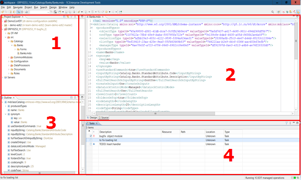
Open the Files Perspective
You can access the perspective in several ways:
-
Click
(Open Perspective)Files in the Perspective Bar -
Click Window > Perspective > Open Perspective > Other... > Files
The default layout of the Files perspective includes the following elements:
-
Project Structure panel This panel displays the application structure as a collection of regular files instead of a tree of configuration objects
-
Editor Area This area can automatically open different editors, such as the XML editor
-
Schema panel This panel displays the structure of the file opened in the editor For example, the structure of types in an XML document
-
Tasks panel This panel shows a list of tasks that need to be completed or have already been completed
Project Structure Panel
The Project Structure panel presents the application structure as a collection of regular files rather than a configuration object tree
This panel is included by default in the Files, Debug, and Data Schema perspectives
Open the Project Structure Panel
Click Window > Show View > Other… > General > Project Structure
Chapter 6. Infobases
Infobase
Infobase is an instance of a 1C:Enterprise application. It is a logically unified system that includes at least two configurations, a database, and additional information required for administration.
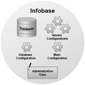
To simplify, the elements of an infobase serve the following purposes:
-
Configuration is the application that runs.
-
Database is the data entered and modified by users.
-
Administrative Data includes elements like the list of users and their permissions.
A single configuration can have multiple infobases, each containing different data and user access settings.
Every infobase contains two configurations:
-
Database Configuration is the runtime configuration used by application users. It cannot be directly edited. It can only be modified through the system operation Update Database Configuration.
-
Main Configuration is the configuration that can be edited directly in Designer or loaded from XML files.
The development process involves modifying the main configuration. To make these changes available to users, the database configuration must be updated. This process merges the main configuration with the database configuration, and the platform restructures the database if needed. Restructuring occurs only when there are changes in the structure of the tables storing the data.
More details about how 1C:EDT interacts with an infobase can be found here.
1C:Enterprise operates in two modes: file mode and client-server mode. Each mode uses a different type of infobase.
File Infobase
1C:Enterprise file mode is designed for personal use or for a small number of users in a local network.
In this mode, the infobase is stored in a single file: 1Cv8.CD. This is called a file infobase.
A file infobase is managed by a file-based DBMS developed by 1C, which is built into the platform.
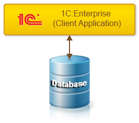
Various client applications can be used with a file infobase. To do this, different 1C:Enterprise components must be installed:
Client-Server Infobase
Client-server mode is designed for workgroups and enterprise-level deployments. It is based on a three-tier client-server architecture.
In this mode, the infobase is stored in a supported database management system, and interaction between client applications and the DBMS is handled by the 1C:Enterprise server cluster.
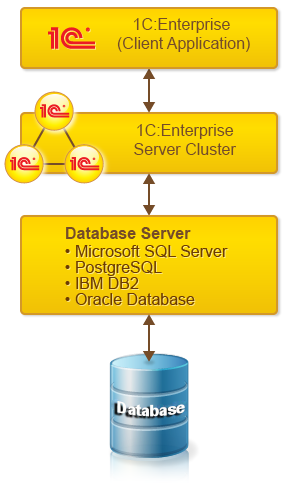
Various client applications can be used with a client-server infobase. To do this, different 1C:Enterprise components must be installed:
Infobase Dump File
An infobase can be exported to a .dt file. This file is called an infobase dump file. This operation is available for both file and client-server infobases.
The reverse operation is also possible: importing an infobase from a .dt file.
A .dt file contains both the configuration and user data, serving as a complete snapshot of the infobase, independent of the infobase type.
A .dt file can be used to transfer an infobase from a file-based DBMS to a client-server DBMS. Also, you can use it to share an infobase with a colleague or technical support.
Configuration File
A configuration stored in an infobase can be exported to a .cf file. This file is called a configuration file.
A .cf file does not contain user data. It can be imported into another infobase to create another instance of the same application.
Create, Add, Update, and Delete an Infobase
Create a New Infobase and Add It to the List
Troubleshooting: If you want to create a client-server infobase, ensure that the server components of 1C:Enterprise and a platform-supported DBMS are installed. See details.
-
Click
 (Add...) in the Infobases panel or Add... in its context menu.
 -
Select Create New Infobase.
-
Click Next.
-
Select the infobase content.
-
To create an infobase with an empty configuration, select Create Infobase Without Configuration....
-
To create an infobase from a pre-installed template, select Create Infobase from Template, then choose one of the available templates.
-
-
Click Next.
-
Enter the infobase name.
-
If necessary, specify the 1C:Enterprise platform version to be used for creating the infobase. By default, 1C:EDT uses the highest available platform version.
-
Select the infobase type.
-
To create a file-based infobase, select On This Computer or LAN Computer.
-
To create a client-server infobase, select On 1C:Enterprise Server.
-
-
Click Next.
-
Specify the directory where the file-based infobase will be located or enter the parameters for the 1C:Enterprise cluster and DBMS where the client-server infobase will be stored (see 1C:Enterprise documentation for details).
-
Click Next and modify the startup parameters if necessary.
-
Click Finish. The infobase will be created, added to the Infobases panel, and highlighted.
Add an Existing Infobase to the List
If you need to add an infobase to the list that is not currently in the 1C:Enterprise list of infobases, follow these steps:
-
Click
(Add...) in the Infobases panel or Add... in its context menu. -
Select Add Existing Infobase to the List.
-
Click Next.
-
Select the infobase type.
-
If the infobase is file-based, select On This Computer or LAN Computer.
-
If the infobase is client-server, select On 1C:Enterprise Server.
-
If the infobase is published on a web server, select On Web Server.
-
-
Click Next.
-
Specify the location of the infobase (see 1C:Enterprise documentation for details).
-
Click Finish. The infobase will be added to the Infobases panel and highlighted.
Modify Infobase Properties
In the Infobases panel, double-click the infobase.
Refresh the Infobase List
If you started 1C:EDT and then the list of infobases was changed using 1C:Enterprise tools, you can refresh the list in 1C:EDT. To do this, click (Refresh) in the Infobases panel.
Remove an Infobase or Group
To remove an infobase or group from the list, click Delete in its context menu. You can select multiple items in the list by holding down Ctrl. The number of selected items will be displayed in the lower left corner of the main window.
1C:EDT will remove only the records from the infobase list. Infobases stored in the local file system or on servers will not be deleted.
When deleting a group record, all infobase records within it will also be deleted.
Records of infobases imported from the shared infobase list cannot be deleted.
Delete a File-Based Infobase
A file-based infobase can be removed not only from the list but also physically deleted from disk. To do this:
-
Click Delete in its context menu.
-
Check the box Delete infobase contents on disk (cannot be undone).
-
Click Yes.
Load and Unload Infobase Content
Load Infobase from a .dt File
-
Click Load Infobase... in the context menu of the selected infobase.
-
In the File field, specify the location of the .dt file.
-
Click Done.
For more details, see 1C:Enterprise documentation.
Dump Infobase to a .dt File
-
Click Dump Infobase... in the context menu of the selected infobase.
-
In the File field, specify the location where the .dt file will be created.
-
Click Done.
For more details, see 1C:Enterprise documentation.
Save Configuration to File
-
Click Save Configuration to File... in the context menu of the selected infobase.
-
In the File field, specify the location where the .cf file will be created.
-
Select the configuration or one of the extensions whose configuration should be unloaded.
-
Click Done.
Open an Infobase in Designer
If you're modifying a configuration, you may need certain operations that are not supported in 1C:EDT. For example, editing distribution and support rules or creating distribution packages. These actions can be run in 1C:Enterprise Designer.
To open an infobase in Designer, click Run Designer in the context menu of the infobase.
Infobase Access Settings
To run and debug a developed configuration, 1C:EDT must export it to an infobase. For 1C:EDT to interact with the infobase, you need to specify access settings, at a minimum, the user account that 1C:EDT will use to connect to the infobase. Usually, this is a user with administrative privileges because 1C:EDT will perform operations such as exporting and importing configurations from XML files and updating the infobase configuration.
1C:EDT saves access settings for each infobase. These settings are available not only within a single project or workspace but also across different workspaces within the same local installation of 1C:EDT.
This is convenient because the same infobase can be used over time for different projects, and you will not have to set up the connection again. In simple terms, once configured, it is ready to use whenever needed.
In many scenarios, 1C:EDT automatically prompts you to configure access to an infobase when it detects the need for it. This happens, for example, when importing a configuration from an infobase into a new project.
At the same time, you can always change these settings if the infobase content has changed, such as users being modified, or if there is a need to specify additional parameters, such as authentication for the configuration repository.
Open Access Settings
In most cases, 1C:EDT automatically opens this dialog when performing certain actions. To open the dialog manually, follow these steps.
-
In the Infobases panel, select the required infobase.
-
In the Properties panel, click Edit in the Access Settings field.
Set a User for Infobase Interaction
Troubleshooting: If you are unsure about the users available in the infobase, open the infobase in Designer first and check which users exist.
-
Open the access settings.
-
In the Access Type field, select the authentication method used by the infobase.
-
OS: authentication via the operating system (see 1C:Enterprise documentation for details).
-
Infobase: authentication via 1C:Enterprise (see 1C:Enterprise documentation for details).
-
Enter the username and, if necessary, the password and additional parameters.
-
Click OK.
Platform Version for Infobase Interaction
Once an infobase is linked to a project, such as during configuration import, 1C:EDT sets the 1C:Enterprise platform version to be used for interaction with the infobase.
The platform version is specified using a version mask, which matches the project's version mask. For example, 8.3.22. As a result, the highest installed version that fits the mask will be used for interaction with the infobase.
In some cases, this may be inconvenient. For instance, if the infobase is client-server and the highest compatible platform version does not have server components installed. In this case, you can:
-
you can either set a specific version of the platform to be used with the mask, affecting all operations that use the mask, such as application launches and imports into new projects,
-
or specify the required platform version only in the infobase access settings.
To open the access settings for modifying the platform version, follow these steps.
-
In the Navigator panel, select the project linked to the required infobase. The linked infobase name is shown in angle brackets after the project name.
-
Open the Applications panel.
-
Double-click the application linked to the project.
-
Click Edit in the Access Settings field.
-
In the Platform field, select the required platform version instead of the mask.
-
Click OK.
Infobase Connected to a Configuration Repository
If the infobase linked to a project is connected to a configuration repository, in addition to authentication for the infobase, authentication parameters for the repository may be required.
To prevent these authentication requests from interfering with automatic configuration updates, specify the repository username and password in the infobase access settings.
/ConfigurationRepositoryN <username>
/ConfigurationRepositoryP <password>-
Open the access settings.
-
In the Additional Parameters field, enter the username and password for repository access.
-
Click OK.
Publishing an Infobase on a Web Server
1C:Enterprise enables client applications to interact with infobases over the internet.
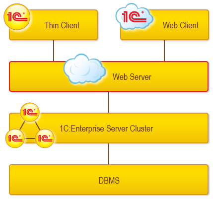
The web client connects through a web server (Apache or Internet Information Services) where the infobase must be published in advance. Publishing an infobase involves the following steps:
-
Registering the web server extension module for the associated web server.
-
Registering a virtual application on the web server.
-
Creating the virtual application's directory and placing the publication file (default.vrd) there, followed by its configuration.
-
Assigning user permissions for the directory containing the database file (only for the file-based mode).
For more details on publishing, see 1C:Enterprise documentation.
Configure Permissions
To successfully interact with the web server, the operating system user must have certain permissions:
Windows
On Windows Vista and later, it is not enough for the user running 1C:EDT to be part of a group with administrative privileges. 1C:EDT must be run as an administrator. To do this, right-click the 1cedt.exe file in Explorer and select Run as Administrator.
Linux
The user performing the web server publication must have write permissions for the httpd.conf file and the directory containing default.vrd.
Publish an Infobase on a Web Server
Troubleshooting: Before publishing, ensure that the 1C:Enterprise platform you want to use includes components for web server interaction:
There are several ways to publish an infobase on a web server:
-
From the Infobases panel: click Publish Infobase... in the context menu of the desired infobase.
-
From the Navigator panel (if the project is linked to an infobase): click Publish Infobase... in the project’s context menu.
-
From the Web Servers panel: click
 (Publish Infobase...) in the command bar or Publish Infobase... in the context menu of the web server where you want to place the publication.
By default, the following components are published:
-
All Web Services of the configuration and extensions contained in the infobase.
-
All HTTP Services of the configuration and extensions contained in the infobase.
If necessary, you can exclude certain components from the publication.
Field Descriptions
- Publish Infobase: the infobase to be published. If you started the wizard from the Infobases panel, you cannot change the selected infobase.
- Platform Version: the platform version whose web server extension will be registered on the web server.
Important: All infobases published on the web server will use the web extension of the most recently published version.
- Web Server for Publication: the web server where the publication will be run.
- Publication Name: the publication name. Allows you to distinguish one publication from another.
- Publication Location: specifies the physical directory on disk where the
default.vrdfile will be stored and where the web server's virtual directory will be mapped. The directory must exist. - Temporary Files Directory.
- Publish Thin and Web Clients: if checked, the published infobase can be accessed via the thin and web clients.
- Publish Standard OData Interface: if checked, the published infobase can be accessed via the OData interface.
- Publish Analytics System: if checked, the launched application's interface will include a command to open the 1C:Analytics web interface.
- Debug settings.
- Enable Debugging: if checked, debugging will be enabled for the application using this publication.
- Debug URL: the protocol and address of the debugger that 1C:EDT will connect to for debugging the running application.
- Progressive Web Application Name: the name of the progressive web application for this publication.
Other parameters are similar to those used when publishing in 1C:Enterprise Designer. For more details, see 1C:Enterprise documentation.
Troubleshooting: If the publication does not take effect, check the permissions settings.
Edit Publication
-
Select the project in the Navigator panel.
-
Double-click the application associated with the project in the Applications panel.
-
Click
 (Edit Selected Item) in the publication command bar of the application editor.
For field descriptions, see here.
Delete Publication
-
Select the project in the Navigator panel.
-
Double-click the application associated with the project in the Applications panel.
-
Click
 (Delete Current Item) in the publication command bar of the application editor.
Infobases Panel
The panel Infobases displays a list of bases registered on your computer.
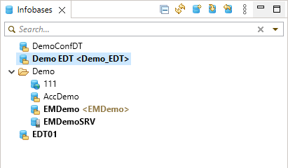
This panel in collapsed form is included by default in the perspective 1C:Enterprise.
Open the Infobases Panel
Click Window > Show View > Other… > 1C:Enterprise > Infobases.
1C:EDT fills this panel automatically at startup. The information about bases is taken from the file ibases.v8i. This is the same file used by client applications of 1C:Enterprise (see 1C:Enterprise documentation). 1C:EDT applies the same settings for this list, such as sorting and displaying recently selected infobases, as 1C:Enterprise. If you change these settings in 1C:EDT, they will also be changed in 1C:Enterprise.
Information Structure
The list of infobases has a hierarchical structure. Bases are located at the root of the tree and within nested folders.
If the option to display recently selected infobases is enabled, they are shown at the top of the list, followed by the root node Infobases, which contains bases and base groups.
Legend
 Root node Infobases.
 Base group.
 File-based infobase.
 Client-server infobase.
 Infobase published on a web server.
 ,
,  Base imported from the list of shared bases (see 1C:Enterprise documentation).
 A record with errors preventing the base from being used. The error description is shown in a tooltip.
 One of the recently selected bases.
 A base linked to a configuration project. The project name is displayed in angle brackets.
Command Bar
- (Collapse All) Collapses all hierarchy levels in the panel down to the first level.
- (Refresh) Updates the information in the panel.
- (Add...) Adds an infobase to the list.
- (Update Configuration...) Exports the configuration from the project to the infobase (about selecting the platform version) and then updates the database configuration.
- (Import Configuration...) Imports the configuration and extensions, if any, from the infobase into a new configuration project (about selecting the platform version).
- (Show Menu) Opens a drop-down menu containing additional commands for the panel.
- Preferences... opens the parameter group Infobases.
Context Menu
- Add... Adds an infobase to the list.
- Rename... Renames an infobase in the list or an infobase group. The root of the list cannot be renamed.
-
Open Opens the Infobase Properties Editor. Editing properties of infobases added from shared infobase lists is not allowed.
-
Delete Removes the infobase or group from the list. You can select multiple items in the list by holding Ctrl. The number of selected items will be displayed in the lower-left part of the main window.
In all cases except for deleting a file-based infobase, 1C:EDT will only remove the records from the infobase list. The databases themselves, whether located in the local file system or on servers, will not be deleted.
Before removing a file-based infobase, 1C:EDT will prompt you to delete the database files from the hard drive. Infobases imported from shared infobase lists cannot be deleted.
-
Run Designer Launches the 1C:Enterprise platform and opens the infobase in Designer mode (about selecting the platform version).
-
Update Configuration... Exports the configuration from the project to the infobase (about selecting the platform version) and then updates the database configuration.
-
Import Configuration... Imports the configuration and extensions, if any, from the infobase into a new configuration project (about selecting the platform version).
-
Import Extensions... Imports extensions from the infobase into new extension projects.
-
Save Configuration to File... Saves the configuration or extension contained in the infobase to a .cf file.
-
Dump Infobase... Exports the infobase to a .dt file.
-
Load Infobase... Loads an infobase from a .dt file.
-
Publish Infobase... Publishes the infobase on the web server.
-
Publish Mobile Application... Publishes the mobile application on the web server.
-
Administration menu contains commands that launch the web client and open several standard features for technical specialists (see 1C:Enterprise documentation for details). Commands are only active for those infobases that are published on the web server;
-
Users... opens the standard Users feature. Allows you to modify the user list (see 1C:Enterprise documentation for details);
-
Active Users... opens the standard Active Users feature. Displays a list of users currently using in the 1C:Enterprise system (see 1C:Enterprise documentation for details);
-
Event Log... opens the standard Event Log feature. Allows you to view the event log (see 1C:Enterprise documentation for details);
-
Authentication Lock... opens the standard Authentication Lock feature. Allows you to view the list of users whose authentication is blocked, unlock those users, and configure the mechanism that automatically blocks users after password brute-force attempts (see 1C:Enterprise documentation for details);
-
Event Log Options... opens the standard Event Log Options feature. Provides access to event log settings for the infobase (see 1C:Enterprise documentation for details);
-
Infobase Regional Settings... opens the standard Infobase Regional Settings feature. Allows you to edit the regional settings of the infobase (see 1C:Enterprise documentation for details);
-
Set License Client Settings... opens the standard Set License Client Settings feature. Allows you to specify access parameters to the 1C:ITS portal to validate software licensing (see 1C:Enterprise documentation for details);
-
Infobase Settings... opens the standard Infobase Settings feature. Provides access to the infobase parameter configuration dialog (see 1C:Enterprise documentation for details);
-
Obtain License... opens the standard Obtain License feature. This dialog allows you to activate a software license without using Designer (see 1C:Enterprise documentation for details);
-
Refresh Updates the information in the panel.
Managing the List of Infobases
Show Recently Selected Bases
At the top of the list, 1C:EDT can display the most recently selected bases. This helps quickly find a base that was recently used.
To enable or disable the display of recently selected bases:
-
Open the parameter group Infobases.
-
Select or clear the checkbox Show Recently Selected Infobases.
-
If the checkbox is selected, specify the number of bases to display as recently selected in the field Remember Recently Selected.
-
Click Apply and Close.
Sort the List
Bases can be arranged either in ascending order by name (default) or in the order in which they were added to the file ibases.v8i.
To change the sorting order:
-
Open the parameter group Infobases.
-
Select or clear the checkbox Sort by Name.
-
Click Apply and Close.
Find a Base in the List
To find a base in a long list, use the search field. Start typing the base name in the field at the top of the panel. 1C:EDT will automatically filter the list and display only the matching bases.
In the search field, you can use control characters:
- * Replaces any set of characters.
For example, *base will find all names containing the substring base.
- ? Replaces any single character.
For example, ????base will find Infobase but not New Base.
- \ Escapes (treats as regular characters) *, ?, and \ if they need to be found explicitly.
For example, *base\* will find Important base*.
To restore the full list, click ![]() on the right side of the field.
on the right side of the field.
To avoid retyping the same search queries over and over, you can select one of the previously used entries. Click ![]() and choose the appropriate entry.
and choose the appropriate entry.
Add a Group of Infobases
To add a group to the list for placing infobases in it, follow these steps.
-
Place the cursor in the hierarchy where you want to add a new group.
-
Click
(Add...) in the Infobases panel or Add... in its context menu. -
Select Create New Group and click Next.
-
Enter the group name and click Finish.
Rename an Infobase or Group
- Click Rename... in the context menu of the infobase or group.
- Enter a new name and click OK.
Move Infobases to Another Group
- Click the required infobase to select it. To move multiple infobases, select them while holding Ctrl.
- Drag the infobases to the desired group.
View the Main Properties of an Infobase
- Click the required infobase to select it.
- In the Properties panel, review the main properties of the infobase.
Edit Infobase Properties
To open the infobase properties in the editor, double-click the required infobase.
Location of Configuration Templates and Updates
- Open the Infobases. Templates parameter group.
- Edit the list of directories and click Apply and Close.
To learn more about template directories, see 1C:Enterprise documentation.
Infobases Parameter Group
The Infobases parameter group allows you to customize the appearance of the infobase list in the Infobases panel.
Open the Infobases Parameter Group
There are two ways to open this group.
-
From the Infobases panel, click
(Show Menu) then Preferences.... -
From the main menu, click Window > Preferences... > V8 > Infobases.
Infobases Templates Parameter Group
The Infobases. Templates parameter group allows you to specify the directory where configuration templates and updates are stored.
For example, this list can include a company-wide template directory and a template directory used for local tasks.
Open the Infobases Templates Parameter Group
- Open the parameter group Infobases.
- In the Infobases branch, select the nested Templates branch.
Chapter 7. Web Servers
To run and debug desktop applications using the web client or to develop mobile applications, a web server is required.
If you are using Windows or Linux, you can use one of the built-in web servers in 1C:EDT to publish infobases:
-
Built-in Web Server is a web server included in 1C:EDT. It can only be used for publishing and debugging mobile applications. It starts and stops quickly.
-
Built-in Apache 2.4 is a web server included in 1C:EDT (available only on Windows). It can be used for publishing and debugging both infobases and mobile applications.
-
1C:Link: a web server located in the 1C:Link service. 1C:EDT is integrated with 1C:Link, allowing you to publish infobases on this service.
On Windows, 1C:Link is supported without additional configuration.
On Linux, 1C:Link is supported if an Apache web server is manually installed. The path to Apache must be specified in 1C:EDT settings.
On macOS, 1C:Link is not supported.
If you are using macOS or if the built-in web servers do not meet your needs, you must install one of the web servers supported by the 1C:Enterprise platform. More details are available in the 1C:Enterprise documentation.
Web Servers Panel
1C:EDT provides the Web Servers panel for managing web servers. It displays a list of web servers installed on your computer, built-in servers, and publications hosted on these servers.
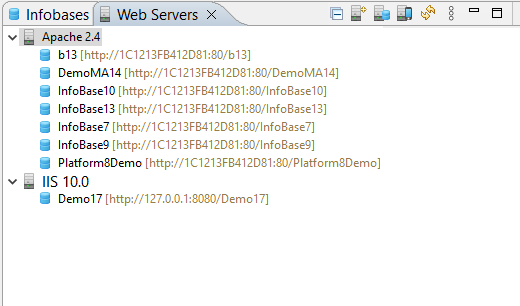
This panel is not included in any perspectives and is not displayed by default.
Open the Web Servers Panel
Click Window > Show View > Other… > 1C:Enterprise > Web Servers.
On the first startup, 1C:EDT attempts to automatically detect installed web servers and adds any found to the panel.
For Apache, automatic detection is only available if the server was installed using an installer (Windows) or through a package manager (Linux). If Apache was installed by extracting an archive to a directory, 1C:EDT will not automatically find it. In this case, you can add it manually.
Information Structure
The list of web servers has a hierarchical structure. At the top level, there are installed and built-in web servers. Each web server contains a list of publications.
Within each web server, you can enable additional grouping of publications by type if there are many publications.
Legend
 : Web server
 : Publication
 : Group of publications of the same type
Command Bar
- (Collapse All) Collapses all hierarchy levels in the panel down to the first level.
 (New) Adds a web server to the list.
- (Publish Infobase...) Publishes the infobase on the web server.
 (Publish Mobile Application...) Publishes the mobile application on the web server.
- (Refresh) Updates the information in the panel.
- (Show Menu) Opens a drop-down menu containing additional commands for the panel.
- Group Publications by Type If this button is selected, publications of infobases and mobile applications will be displayed in individual branches for each web server.
- Flat View for Publications If this button is selected, all publications on a single web server are displayed as a single list.
Context Menu
- New Adds a web server to the list.
- Open Opens the web server properties editor or the Publication Editor.
- Rename... Renames the web server in the list.
- Copy Copies the publication to the clipboard.
- Insert Inserts a publication from the clipboard.
- Delete Removes web server information from the list.
- Publish Infobase... Publishes the infobase on the web server.
- Publish Mobile Application... Publishes the mobile application on the web server.
- Update Publication Updates the publication on the web server.
- Restart Web Server Restarts the web server.
- Refresh Updates the information in the panel.
Managing the Web Server List
Group by Publication Type
To display infobase publications and mobile application publications separately for each web server, click ![]() (Show Menu): Group Publications by Type in the Web Servers panel.
(Show Menu): Group Publications by Type in the Web Servers panel.
To cancel this grouping, click Flat View of Publications in the same place.
Rename a Web Server
Click Rename... in the web server's context menu.
Remove a Web Server from the List
To remove a web server entry from the list, click Delete in the web server's context menu.
Publications Parameter Group
Along with panel commands, the Publications parameter group allows you to manage publication grouping in the Web Servers panel.
Open the Publications Parameter Group
Click Window > Preferences... > V8 > Publications.
Built-in Web Server Settings Parameter Group
The Built-in Web Server Settings parameter group allows you to configure the built-in web server settings.
Open the Built-in Web Server Settings Parameter Group
Click Window > Preferences... > V8 > Publications > Built-in Web Server Settings.
Field Descriptions
- Built-in Web Server Port: the port used by the web server.
- Configuration Location: the full path to the built-in web server configuration file.
- Default Directory for Publications: the default directory for publishing mobile applications. The full publication path is determined by this setting and the publication name.
1C:Link Parameter Group
The 1C:Link parameter group allows you to specify the path to the installed Apache web server. This setting is used on Linux to interact with the 1C:Link service.
On Windows, these parameters are not used and do not appear in the settings.
Open the 1C:Link Parameter Group
Click Window > Preferences... > V8 > 1C:Link.
Add, Update, and Remove a Server
Add an Installed Apache Web Server to the List
If 1C:EDT did not automatically detect the web server, you can add it manually. Click (New) in the Web Servers panel.
Update the Web Server List
If you installed a web server after starting 1C:EDT, update the list in 1C:EDT. Click (Refresh) in the Web Servers panel.
Change the Built-in Web Server Port
To change the port used by the built-in web server:
-
Double-click Built-in Web Server in the Web Servers panel.
-
Enter the new value in the Port Number field.
-
Press Ctrl+S.
Remove a Web Server from the List
To remove a web server from the list, click Delete in its context menu.
Rename a Web Server
To rename a web server, click Rename... in its context menu.
Restart a Web Server
To restart a web server, click Restart Web Server in its context menu. This command is executed only if 1C:EDT is running with administrative privileges.
Chapter 8. Writing Code
1C:Enterprise Language
1C:Enterprise language is used to define the logic of an applied solution during configuration development. It is a domain-specific programming language designed to be accessible not only to professional developers. All language operators have both English and Russian syntax, and they can be used interchangeably in a single source file.
Code written in the 1C:Enterprise language is contained in modules, which are located in various parts of the configuration.
The language has object-oriented features. For example, access rules for properties and methods of applied objects (such as documents, catalogs, etc.) are similar to the properties and methods of objects in other object-oriented languages. However, applied object types cannot be defined within the language itself. they are set visually.
Variable typing in the language is dynamic, meaning the variable type is determined by its value. Declaring variables explicitly is optional. Implicit declaration occurs when a variable is first assigned a value on the left side of an assignment operator. Explicit variable declaration is possible using the Var operator. The language supports arrays, structures, maps, and other universal value collections.
For more details about the 1C:Enterprise language, refer to the 1C:Enterprise documentation.
1C:Enterprise Language Contexts
1C:Enterprise Language Context or simply Context refers to a set of functions, procedures, properties, types, objects, methods, and events available in a given module or within a specific method. In other words, when working in a module, you cannot use everything listed in Syntax Assistant. Only a specific subset that applies to that module. This subset is called the context. For more details, see: .
The two largest contexts are: Client Context and Server Context The reason for their existence is that applied solutions generally operate in a client-server environment.
In this environment, the user interacts with a client application. At specific points in time (events), program code written in modules executes within the client context.
The client application, in turn, interacts with the 1C:Enterprise server cluster. At certain moments (events) or in specific situations (such as calling a server method), program code written in modules executes within the server context.
Since 1C:Enterprise allows applied solutions to function over the internet, the client application and the server cluster may run on different computers, in different cities, or even in different countries.
In simpler cases, the client application and the server cluster may reside on the same machine, or a server cluster might not be used at all (in file-based mode). However, this does not affect how modules are written. They are always developed to function in the general case, which is the client-server mode. If a simpler system deployment is used in reality, the platform emulates the necessary contexts during module execution.
The execution environment for client applications differs significantly from that of the server cluster. For example: A client application interacts with a user, allowing for interactive elements. To support this, the 1C:Enterprise language provides a wide range of interface-related types that are part of the client context.
On the other hand, where the server cluster runs, there is no user. Accordingly, types intended for interacting with the user interface are not available in the server context. At the same time, the cluster interacts with the database management system, so the server-side 1C:Enterprise language provides applied types that allow reading and writing business data from the database. These types exist in the server context, but they are not available in the client context.
One of the most noticeable places where both client and server contexts appear is in form modules. Form modules can execute both in client applications and on the server cluster. Therefore, as a rule, each method in such modules is preceded by a compilation directive.. It defines the context in which the method will exist within the module.
The directive &AtServer means that the procedure will exist in the module when it executes on the server. When executed on the client, this procedure will not be present.
Example of using the &AtServer directive:
&AtServer
Procedure OnCreateAtServer(Cancel, StandardProcessing)
The directive &AtClient means that the procedure will exist in the module when it executes on the client. When executed on the server, this procedure will not be present.
Example of using the &AtClient directive:
&AtClient
Procedure OpenCommand(Command)
In addition to client and server contexts, there are also more specific contexts. This is because there are several types of client applications (thin client, web client, thick client, mobile client), and the server-side is available not only for desktop applications but also for mobile applications. Each client application and each server-side component has its own execution characteristics and its own context. These contexts can be found in Syntax Assistant, in the descriptions of all types, their methods, properties, and events. They are listed in the Availability section.
For the type HTTPServiceRequest, the availability is specified as follows:
Availability: Server, thick client.This means that the type HTTPServiceRequest can be used in the server context, as well as in the client context, but only when the thick client is running. If you try to execute the same code in the thin client, you will get an error because this type is not available in the thin client context.
For the type Array, the availability is specified as follows:
Availability: Thin client, web client, mobile client platform, server, thick client,
external connection, mobile application (client), mobile application (server).
This means that the type Array can be used in almost all client and server contexts, including mobile devices.
Open Module
Open the Application, Session, or External Connection Module
In the Navigator panel, click Open Application Module, Open Session Module, or Open External Connection Module in the configuration context menu.
If the Configuration Properties Editor is already open, you can switch to these modules by selecting the resepctive tab in the editor.
Open Object Modules, Manager Modules, Record Set Modules, and Value Manager Modules
- In the Navigator panel, select the configuration object that the module belongs to.
- Click Open Object Module, Open Manager Module, Open Record Set Module, or Open Value Manager Module in the context menu.
If the Required Configuration Object Editor is already open, you can switch to these modules by selecting the respective tab in the editor.
Open the Form Module
- In the Navigator panel, select the required form.
Common forms are located under General - Common Forms.
Object configuration forms are located within these objects under Forms.
- Click Open Form Module in the context menu.
If the form editor is already open, you can switch to the form module by selecting the Module tab.
Open the Command Module
- In the Navigator panel, select the required command.
General commands are located under General - General Commands.
Configuration object commands are located within these objects under Commands.
- Double-click the command.
Open the Common Module
- In the Navigator panel, select the required common module.
- Double-click the common module.
1C:Enterprise Language Editor
-
Commands:
The 1C:Enterprise Language Editor allows you to edit configuration modules.
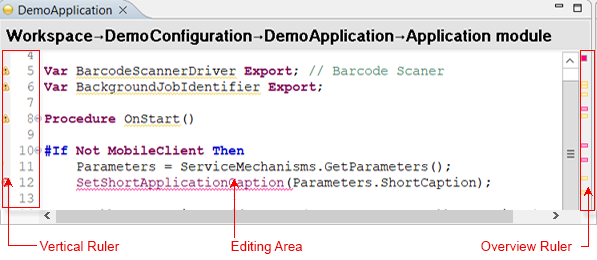
This editor cannot be opened on its own. It opens within the context of editing a configuration when you open a module. Additionally, the 1C:Enterprise Language Editor opens in other scenarios related to navigating to a specific line of source code.
Editor Areas
The editor window contains several functional areas:
Vertical Ruler
The vertical ruler scrolls along with the module text and displays information related to the module lines shown on the screen:
-
module line numbers
-
icons for syntactic structure grouping —
 .
. -
quick differences
-
information about revision
-
results of performance measurement.
Editing Area
The editing area displays:
-
module text
-
results of integrated debugging.
Overview Ruler
The overview ruler does not scroll. it represents the entire module. The position of markers on the overview ruler corresponds to their relative position in the module. Markers indicate the same elements as on the vertical ruler: warnings, errors, tasks, bookmarks, and more. Hovering over a marker displays a text description, and clicking it navigates to the corresponding line. An icon at the top of the panel shows the highest severity of errors and warnings in the module.
Legend
 Warning
 Text fragment associated with a warning
 Error
Error Text fragment associated with an error
 Error with available quick fix options
 Line that will be executed during step execution
 Enabled breakpoint
 Enabled conditional breakpoint
 Disabled breakpoint
 Inactive breakpoints
- Expanded syntactic structure
 Collapsed syntactic structure
 Task
Task Bookmark
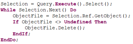 Current line and current identifier
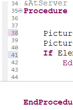 Quick differences
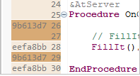 Revision information
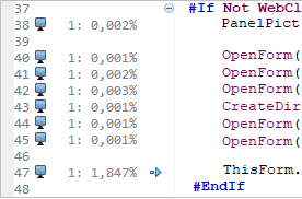 Performance measurement results
 Results of integrated debugging
Mouse Actions and Dragging
-
Vertical Ruler
-
Hovering over a warning icon
, error icon , breakpoint icon , task icon , or bookmark icon displays a tooltip with a text description. -
A single click on a warning
or error icon may open the quick fix window if 1C:EDT provides automatic correction options. -
Dragging in the line number area selects a range of lines.
-
Overview Ruler
-
Hovering over a marker displays its description in a tooltip.
-
A single click on a marker highlights the corresponding line in the editor.
-
A single click displays the module fragment corresponding to the indicated position.
1C:Enterprise language Color Scheme
Syntactic structures of the 1C:Enterprise language are highlighted in different colors to improve code readability.
A standard set of colors is used for different syntactic structures. To modify the colors, click Preferences... in the context menu of the editing area. Then open the Syntax Highlighting parameter group.
These settings can also be accessed from the main window menu by clicking Window > Preferences... > V8 > 1C:Enterprise language > Syntax Highlighting.
Context Menu of the Vertical Ruler
-
Disable Breakpoint Disables a breakpoint in the selected line. During debugging, 1C:EDT will not analyze this breakpoint and will not stop program execution.
-
Enable Breakpoint Enables a breakpoint that was previously disabled in the selected line. During debugging, 1C:EDT will analyze this breakpoint and stop execution if necessary.
-
Breakpoint Adds an unconditional breakpoint or removes an existing breakpoint at this line.
-
Add Bookmark... Adds a bookmark linked to the selected module line.
-
Delete Bookmark Deletes the bookmark associated with the current module line.
-
Add Task...: Adds a task. Task will be linked to the selected module line.
-
Delete Task Deletes the task associated with the current module line.
-
Performance Meter The submenu contains the following commands:
-
Show Measurement Results if the checkbox is selected, the vertical ruler in 1C:EDT displays performance measurement results. If cleared, it does not show them.
-
Show Outdated Results after performing a performance measurement, you can modify the line that was measured. In this case, the measurement result displayed in this line becomes outdated. If the checkbox Show Outdated Results is selected, the outdated measurement result will be highlighted in gray text. If unchecked, the outdated measurement result will be hidden.
-
Show Quick Differences: if the checkbox is selected, the vertical ruler in 1C:EDT displays quick differences. If cleared, it does not show them.
-
Show Revision Information: displays revision details in the vertical ruler of the editor. You can configure the color scheme and the type of information displayed in the Revisions submenu.
-
Revisions submenu contains the following commands.
-
Hide Revision Information hides revision details in the vertical ruler.
-
Color by Date newer commits are highlighted with a darker background.
-
Color by Author changes made by each author are highlighted with a unique background color.
-
Combined Coloring changes made by each author are highlighted with a unique background color. Newer commits are highlighted with a darker background.
-
Show Author If the checkbox is selected, the vertical ruler displays the commit author's name.
-
Show ID If the checkbox is selected, the vertical ruler displays the commit author's name.
-
Show Line Numbers if the checkbox is selected, line numbers will be displayed in the vertical ruler of the module. If unchecked, line numbers will not be displayed.
-
Folding submenu contains the following commands:
-
Enable Folding: if enabled, syntax constructs are grouped and collapsed. If disabled, grouping and collapsing are not used. You can configure which constructs are grouped and collapsed. This can be done on the settings page Collapse/Expand Code Section.
-
Expand All expands all syntax structure groupings.
-
Collapse All collapses all syntax structure groupings.
-
Reset Structure resets the grouping settings of syntax structures to their default state. Equivalent to pressing Restore Default Values on the Collapse/Expand Code Section settings page.
-
Preferences... The following parameter groups can be configured: Syntax Highlighting and 1C:Enterprise Language - Templates.
-
Breakpoint Properties... Opens a dialog that allows you to change the properties of a breakpoint, such as hit count and stop condition.
Context Menu of the Editing Area
-
Undo: undoes the last action. The action description is displayed after the command name.
-
Revert File cancels all changes made since the last file save.
-
Save saves the changes made to the file.
-
Open In submenu contains commands that allow you to open a module using other editors available in 1C:EDT or installed on the computer.
-
Show In submenu contains commands that allow you to open the editable file in the operating system’s file explorer or view the properties of the configuration object to which this module belongs.
-
Go to Definition: navigates to the definition of a variable or method at the cursor position. You can return using the Back To command in the Main Window Command Bar.
-
Call Hierarchy: Opens the Call Hierarchy panel and displays the calling or called hierarchy of methods for the selected method.
-
Module Quick Outline: displays the module quick outline.
-
Find References opens the Search panel and displays the calling hierarchy of methods and configuration objects related to the selected method in the panel.
-
Cut Copies the selected text to the clipboard and removes it from the module.
-
Copy copies the selected text to the clipboard.
-
Paste Pastes text from the clipboard into the module.
-
Add Event Handler: Opens the dialo Add Event Handler. The event handler template is added after the method where the cursor is located.
-
Source submenu contains the following commands:
-
Generate Method Comments: Creates a comment template for the procedure or function where the cursor is located or for the definition following the line where the cursor is placed. In this template, sections for explanatory text input are highlighted with markers.
-
Add Annotation to Suppress Warnings This command is useful for lines where the configuration validation has issued a warning
 . The command inserts a service comment before the line where the cursor is located (if it is an executable statement) or before the next executable statement (if the cursor is in an empty line). This comment excludes the line from the validation results, removing the warning.
 -
Create Code Template: adds a new code template The selected text is inserted into the Template field.
-
Enable Strict Typing (@strict-types) in Modules in modules belonging to the selected configuration branches, enables strict typing by adding the annotation //@strict-types at the beginning of the modules.
-
Toggle Comment adds or removes comments on the selected lines (how to select a range of lines).
-
Format formats all modules according to formatting settings.
-
Context Help opens contextual hint.
-
Refactoring submenu contains the following commands:
-
Rename: initiates renaming of a variable, procedure, or function where the cursor is located. Visible occurrences are marked with indicators. After changing the value in any indicator, you can press Enter, and the renaming will be applied across all modules where this variable, procedure, or function is used.
-
Extract Local Variable... opens the Extract Local Variable dialog.
-
Extract Method... opens the Extract Method dialog.
-
Surround With submenu contains the following commands:
-
#Region... surrounds the selected module lines with preprocessor directives
#Region...#EndRegion. After insertion, the fragment designated for entering the region name is highlighted. -
Quick Fix opens the quick fix window if the current line is marked with a warning or error
, for which 1C:EDT has fix suggestions. -
Query Editor... opens the query editor and inserts the result at the cursor position. If the cursor is already inside a query text, the query text is loaded into the editor, and the edited result replaces the existing query text in the module.
-
Add Method to Extension copies the current module, if necessary copies the configuration object it belongs to, and creates an extension event handler.
Trouble: At the time of execution, an extension associated with this project must exist. If multiple extensions are linked to the project, 1C:EDT will prompt you to select one.
-
Format String Wizard... opens the Format String Wizard and inserts the generated result at the cursor position or replaces the selected text. If the cursor is inside a format string, it is loaded into the wizard for editing, and the edited result replaces the existing string in the module.
-
Multilingual String Wizard...: opens the multilingual string wizard and inserts the generated result at the cursor position or replaces the selected text. If the cursor is inside a multilingual string, it is loaded into the wizard for editing, and the edited result replaces the existing string in the module.
-
Query Wizard... opens the query wizard and inserts the generated result at the cursor position or replaces the selected text. If the cursor is inside a query text, the query is loaded into the wizard for editing, and the edited result replaces the existing query text in the module.
-
Query Wizard with Result Processing...: opens the query wizard with result processing and inserts the generated result at the cursor position or replaces the selected text. If the cursor is inside a query text, the query is loaded into the wizard for editing, and the edited result replaces the existing query text in the module.
-
Check: performs a full module validation, similar to what runs when opening or editing a module. This command may be useful when module errors are caused by external factors. For example, if there are errors related to missing XDTO packages in the configuration. You added the required packages, but the module errors did not disappear automatically. In this case, you can run this command, and the module will be checked again.
-
Observation: This command is active during debugging after stopping at a breakpoint. Adds a variable to the Expressions panel so that its value is tracked during step-by-step debugging. In panel Expressions, you can edit the watched expression and, for example, instead of the variable
ExecutionDate, trackBeginningOfMonth(ExecutionDate). -
Inspect: This command is active during debugging after stopping at a breakpoint. evaluates the selected expression. The result is displayed in a pop-up window. The key combination Shift+F9 adds this expression to the Expressions panel.
-
Version Control (Team) submenu contains the following commands.
-
Commit... commits project changes to the local repository.
-
Repository submenu contains the following commands.
-
Push to origin sends changes to the remote repository named "origin".
-
Fetch from Upstream retrieves changes from the upstream repository, from the remote branch associated with the local branch.
-
Push Branch 'branch-name'... sends the selected branch to the remote repository. You can choose a repository or create a new one, select the branch to push, and configure push and fetch settings for the remote repository.
-
Pull fetches changes from the upstream repository and merges them into the current branch.
-
Switch To switches the project to a different branch. The submenu provides options to choose from local branches in the current repository. It also includes options to create a new branch or select from other repository elements such as tags and remote tracking branches.
-
Advanced Options submenu contains additional commands.
-
Assume Unchanged marks a file as Assume Unchanged.
-
No Assume Unchanged removes the Assume Unchanged mark from the file.
-
Remove from Version Control removes the object from Git version control but leaves it in the working tree.
-
Synchronize Workspace synchronizes the working tree with the remote repository. This is done using the Synchronize perspective.
-
Create Patch... creates a patch.
-
Ignore adds the file to .gitignore so that Git ignores it (learn more).
-
Show in Git Repositories Panel opens the project in the Git Repositories panel.
-
Disconnect disconnects all Git Team providers from this project. The Git repository continues to exist, but 1C:EDT no longer interacts with it.
-
Show Local History: Opens the History panel and displays the local history of module changes.
-
Show History opens the History panel and displays resources from the current repository.
-
Show Revision Information: displays revision details in the vertical ruler of the editor. You can configure the color scheme and the type of information displayed in the Revisions submenu.
-
Compare submenu contains the following commands:
-
Local History...: Opens the History panel to select one of the previous local file versions. After selection, compares it with the current version in the Module Comparison and Merging Editor.
-
HEAD Revision Not used in 1C:Enterprise application development. Compares this resource in the working tree with the last commit.
-
Index Not used in 1C:Enterprise application development. compares this resource in the working tree and in the index.
-
Previous Revision Not used in 1C:Enterprise application development. Compares this resource with the previous commit.
-
Branch, Tag, or Reference... Not used in 1C:Enterprise application development. Compares the working tree with the selected branch, tag, or reference.
-
Commit... Not used in 1C:Enterprise application development. Compares the working tree with the selected commit.
-
Replace With: submenu contains the following commands.
-
HEAD Revision replaces the working tree with the last commit.
-
Index replaces the working tree with the index.
-
Previous Revision replaces the working tree with the previous revision.
-
Branch, Tag, or Reference... replaces the working tree with the selected branch, tag, or reference.
-
Commit... replaces the working tree with the selected commit.
-
Preferences...: You can configure parameter groups: 1C:Enterprise Language - Templates and Syntax Highlighting.
Context Menu of the Overview Ruler
- Preferences... The following parameter groups can be configured: Annotations, Quick Diff, and Accessibility.
Basic Editing Techniques
Entering English Characters Without Switching Keyboard Layouts
The syntactic structures of the 1C:Enterprise language include certain characters that are typically located on an English keyboard layout. You can enter these characters without switching to the English keyboard layout by using the Alt key:
-
< and > angle brackets can be entered with Alt+, and Alt+..
-
[ and ] square brackets can be entered with Alt+[ and Alt+].
-
{ and } curly brackets can be entered with Alt+9 and Alt+0.
-
@ at symbol can be entered with Alt+2.
-
# hash symbol can be entered with Alt+3.
-
& ampersand can be entered with Alt+7.
-
' apostrophe can be entered with Alt+'.
-
| vertical bar can be entered with Alt+\.
-
/ slash can be entered with Alt+..
-
XDTO can be entered with Alt+x.
-
HTTP can be entered with Alt+h.
-
DOM can be entered with Alt+d.
Creating Event Handlers
There are two types of event handlers: those with assigned names and those with fixed names.
Assigned names are required for handlers that process events with the same name from different elements within a single module. This occurs in form modules with events from form items.
It is impossible to know in advance how many elements you will create in a form or what their names will be. For this reason, such event handlers have assigned names. These names are formed based on the element name and the event name.
Create a Form Item Handler
- In the form editor, select a form item.
- In the Properties panel, click
 in the field containing the name of the required handler.
At this moment, 1C:EDT links the event of the element with a specific name and assigns the same name to the procedure that will process the event. It inserts the procedure template into the module, allowing you to write the body of the procedure.
Handlers with fixed names are much simpler. They process application events, applied objects, and forms. These are elements of the configuration that either do not depend on you or have unique names and their own modules. For this reason, handlers for such events can be created using simpler methods, such as the context hint or a context menu command.
Create a Handler Using the Context Hint
- Place the cursor in the module line where the procedure declaration should be added.
- Press Ctrl+Space to invoke the context hint.
- Press Ctrl+Space again to switch to the list of available procedures and templates.
- Double-click to select the required procedure.
The handler template will be added to the module.
Create a Handler Using a Menu Command
To create an event handler using a command, select Add Event Handler from the context menu. The cursor position in the module does not matter. A dialog for selecting an event will open, allowing you to choose the required event manually or by entering text in a search field.
Events already processed in the module are displayed in gray. When an event is selected, a syntax hint for that event appears at the bottom of the dialog. After clicking OK, the handler template will be added at the end of the module.
Format String Wizard
The Format String Wizard helps you generate a format string for displaying numbers, dates, and Boolean values. Format strings are used, for example, in the 1C:Enterprise language function Format(). "DLF=DD." is an example of a format string.
ProcessingDate = Format(CurrentSessionDate(), "DLF=DD.").Open the Format String Wizard
- Place the cursor at the position where the format string should be inserted.
- Click Format String Wizard in the context menu.
This wizard provides similar functionality to the Format String Wizard in 1C:Enterprise Designer. More details can be found in the 1C:Enterprise documentation.
Configuring the 1C:Enterprise Language Editor
Syntax Highlighting
Syntax highlighting is configured separately for the 1C:Enterprise language and for different contexts where the query language is used.
To open these settings, click Window > Preferences..., then enter "syntax highlighting" in the search field. You will see all available settings.
Author and Commit Information
The 1C:Enterprise Language Editor can display information about the author and commit in its vertical ruler. You can configure how this information is displayed.
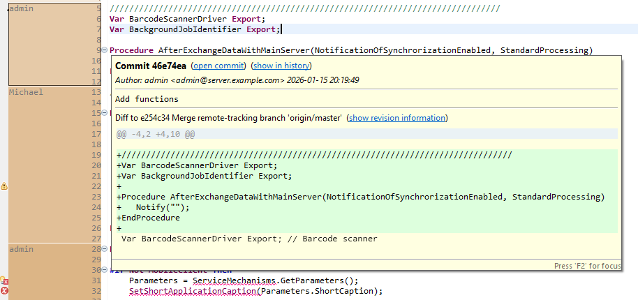
Show Commit Information
- Open the module in the 1C:Enterprise Language Editor.
- Click Show Revision Information in the vertical ruler's context menu.
Show Commit in the History Panel
- Hover over the commit marked in the vertical ruler.
- Click show in history in the pop-up window.
- 1C:EDT will open the History panel and highlight the commit that introduced the changes.
Open Commit in the Viewing Panel
- Hover over the commit marked in the vertical ruler.
- Click open commit in the pop-up window.
- 1C:EDT will open the commit in the viewing panel.
Hide Commit Information
Click Revisions and then Hide Revision Information in the vertical ruler's context menu.
Display Author and Commit Identifier
To display the commit author's name and commit identifier in the vertical ruler, select the following options from the context menu:
-
Revisions Show Author
-
Revisions Show ID.
Configure Commit Coloring
There are several options for coloring commits displayed in the vertical ruler. To select one, click Revisions in the context menu of the vertical ruler.
-
Color by Date newer commits are highlighted with a darker background.
-
Color by Author changes made by each author are highlighted with a unique background color.
-
Combined Coloring changes made by each author are highlighted with a unique background color. Newer commits are highlighted with a darker background.
Collapse/Expand Code Section Parameter Group
The Collapse/Expand Code Section parameter group allows you to specify which syntax constructs of the 1C:Enterprise language will be grouped (first set of fields) and which constructs will be automatically collapsed when opening a module in the 1C:Enterprise Language Editor (second set of fields).
To open this parameter group, click Window > Preferences... > V8 > 1C:Enterprise Language > Collapse/Expand Code Section.
Query Editing
Query Wizard
The Query Wizard allows you to visually construct syntactically correct query text.
Open the Query Wizard
- Place the cursor at the position where the query text should be inserted.
- Click Query Wizard... or Query Wizard with Result Processing... in the context menu.
In the second case, the Query Wizard includes an additional tab to select how the query result will be processed.
This wizard provides functionality similar to the Query Wizard in 1C:Enterprise Designer. More details can be found in the documentation.
Query Editor
The Query Editor allows you to create and edit query text in its raw form.
Open the Query Editor
- Place the cursor at the position where the query text should be inserted.
- Click Query Editor... in the context menu.
Formatting
Formatting Commands
Troubleshooting: The listed formatting commands function only if the formatting option is enabled in the preferences by selecting Enable Formatting. If this option is disabled, the listed commands will not perform any actions.
Format the Entire Module or Selected Fragment
In the module's context menu, click Source > Format.
Format All Project Modules
In the Navigator panel, click Format All 1C:Enterprise Language Modules in the project's context menu.
Automatic Formatting
1C:EDT does not apply automatic formatting when opening or saving modules. Modules are saved exactly as written and opened in the format in which they are stored.
Formatting Settings
Open the Formatting Parameter Group
Click Window > Preferences... > V8 > 1C:Enterprise Language > Formatting.
Export Formatting Parameters to a Text File
- Open the Formatting parameter group.
- Click Export....
- Select a directory, specify the file name and extension.
- Click Save.
Import Formatting Parameters from a Text File
- Open the Formatting parameter group.
- Click Import....
- Select the file containing the formatting parameters.
- Click Open.
- Click Apply and Close.
Apply Standard Formatting Rules
- Open the Formatting parameter group.
- Click Restore Default Values.
- Click Apply and Close.
Apply New Formatting Parameters Independently of Other Settings
To apply only the modified formatting parameters without affecting other 1C:EDT preferences that may also have been changed, click Apply, then  .
.
A visible effect of applying new formatting rules is, for example, a change in page width in the 1C:Enterprise Language Editor.
Parameter Group "Formatting"
The Formatting parameter group allows you to configure module formatting rules.
General Tab
- Max Line Length defines the page width in the 1C:Enterprise Language Editor. If automatic line wrapping rules are set (on the Auto Wrap tab), lines exceeding this length will be wrapped.
- Tab Size specifies the number of characters in a single indentation level if tab characters are not used for syntactic indentation (see the Indentation tab). If tab characters are used for indentation, this field is ignored, and each indentation level consists of one tab character.
- Enable Formatting enables the formatting commands to use the specified rules. If unchecked, formatting commands do not perform any actions.
Blank Lines Tab
- Minimum Consecutive Blank Lines ensures that if the number of blank lines between statements is less than this value, it is increased to match this value.
- Maximum Consecutive Blank Lines limits the number of consecutive blank lines. If the number of consecutive blank lines exceeds this value, it is reduced to match the Minimum Consecutive Blank Lines setting.
- Space Between Parameters in a Method ensures that parameters in a method call are separated by spaces if enabled.

If unchecked, method parameters are not separated by spaces.

Space Between Empty Parameters in a Method Call inserts a space instead of an empty parameter in a method call if enabled.

If unchecked, empty parameters remain unmarked.

Indentation Tab
Indent Within a Method ensures that all child statements have one indentation level if enabled.
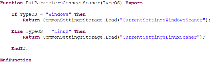
If unchecked, all child statements start at the same position as the method declaration.
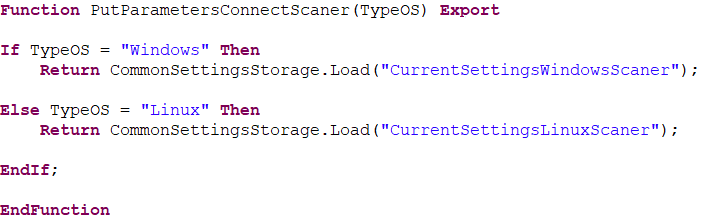
Use Spaces for Tabs ensures that indentation uses spaces instead of tab characters, based on the Tab Size defined on the General tab.
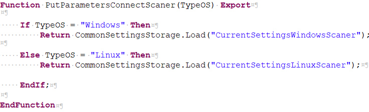
If unchecked, indentation uses tab characters, with one indentation level represented by a single tab.

Auto Wrap Tab
Wrap Type for Binary Expressions: If set to No Wrap, each operator remains on a single line without wrapping.
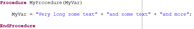
If set to Indent, text exceeding the line length limit is wrapped with one indentation level.
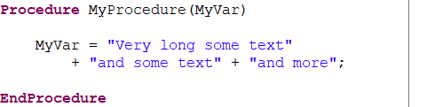
If set to Align, each operand appears on a new line, aligned with the first operand.
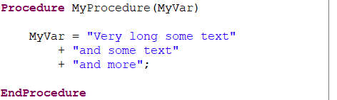
Wrap Type for Method Calls: If set to No Wrap, each method call remains on a single line without wrapping.

If set to Indent, text exceeding the line length limit is wrapped with one indentation level.
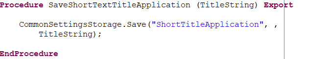
If set to Align, each parameter appears on a new line, aligned with the first parameter.
Wrap Type for Method Parameters: If set to No Wrap, each parameter remains on a single line without wrapping.

If set to Indent, text exceeding the line length limit is wrapped with one indentation level.

If set to Align, each parameter appears on a new line, aligned with the first parameter.
Apply Loose Formatting to the Assignment Operator allows the assignment operation and the expression on its right side to be placed anywhere in the module without modifying their position if enabled.
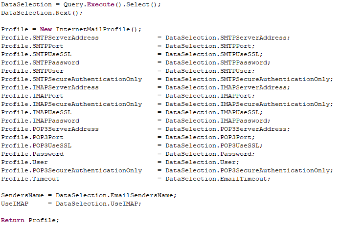
If unchecked, the assignment operation is placed between the left and right expressions, separated by a single space.
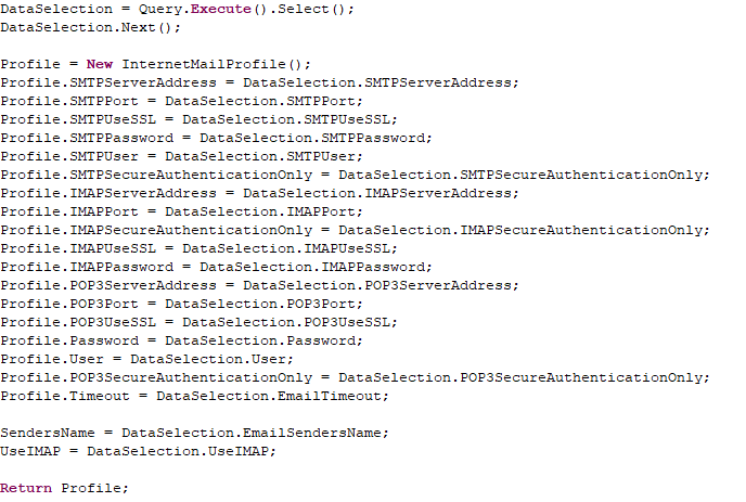
Reference Styles Tab
Keyword Style Reference determines the capitalization style for keywords. If MixedCase is selected, keywords use both uppercase and lowercase letters (CamelCase style).

If lowercase is selected, keywords are written entirely in lowercase.
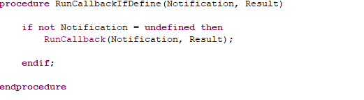
If UPPERCASE is selected, keywords are written entirely in uppercase.
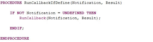
Empty Parentheses When Creating an Object Without Parameters defines whether parentheses are included. If Always Without Parentheses is selected, no parentheses are added after the type identifier.
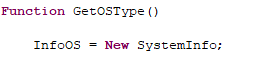
If Always With Parentheses is selected, parentheses are always included after the type identifier.
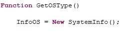
If Do Not Modify is selected, the existing notation remains unchanged.
Always End the Last Expression With a Semicolon ensures that the last expression always ends with a semicolon if enabled.
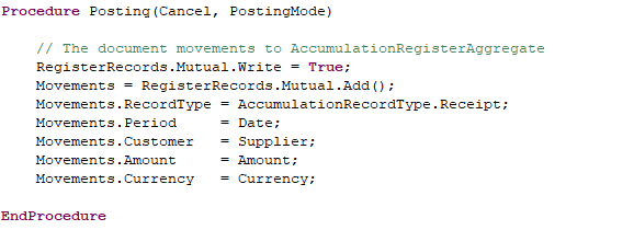
If unchecked, the existing notation remains unchanged. For example, after Currency, a semicolon may be absent.
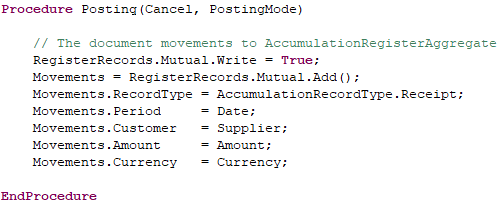
Preprocessor Tab
Ignore Indentation for Preprocessor Directives ensures that preprocessor directives are written without syntactic indentation, and the text within them is formatted independently.
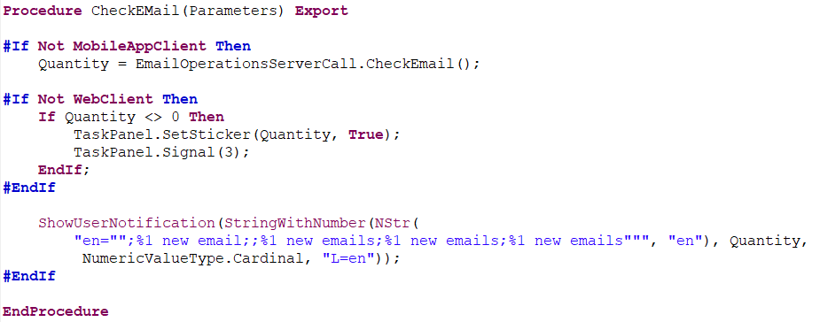
If unchecked, preprocessor directives follow syntactic indentation, and the contained text is formatted accordingly.
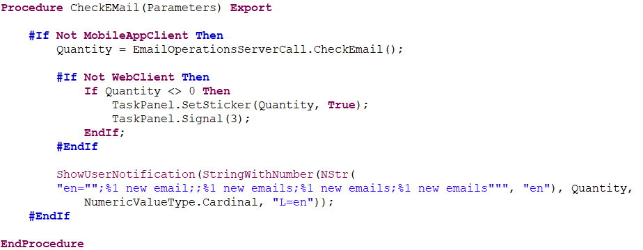
Navigation Within Modules
When developing large configurations, it is important to be able to quickly navigate through a module, locate necessary procedures, analyze call chains upward or downward from the current location, and plan module refinements. 1C:EDT provides several tools that can be used in a way that suits you best.
Find Out Which Procedure I Am In
If you are inside a long procedure and its definition is not visible on the screen, there are two ways to quickly find out the name of the current procedure.
First, 1C:EDT displays the current procedure’s name in the lower panel of the main window, in the center.
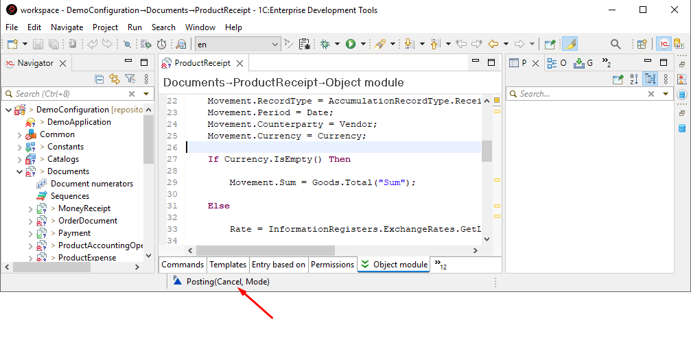
Second, you can open the ER Diagram panel. It will highlight the procedure or preprocessor instruction where the cursor is currently positioned in the 1C:Enterprise Language Editor.
Go to a Procedure with a Known Name
If you are in a module and want to navigate to a procedure with a known name, locate that procedure in the ER Diagram panel and click on it.
If there are many procedures in the panel, you may want to sort them alphabetically first.
Quickly Go to a Known Procedure
If you know the name of the required procedure and do not want to interrupt module editing or scroll through the list of procedures in the ER Diagram panel, you can use the module quick outline.
To open the quick ER diagram, press Ctrl+O. All module procedures and functions will be displayed just as they appear in the ER Diagram panel.
Start typing the procedure or function name, and matching elements will be displayed immediately.
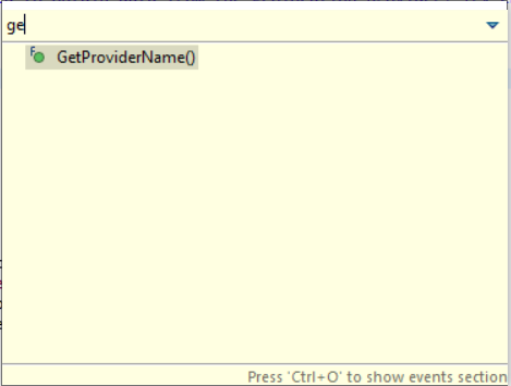
Use the up and down arrow keys to select the desired element and press Enter. The editor cursor will be placed at the declaration of the selected procedure or function.
Similar actions can be run with the mouse.
If you also need event subscriptions in addition to procedures and functions, you can press Ctrl+O again in the quick ER diagram, and the event branch will be displayed.
Go to Declaration
There is often a need to analyze the sequence of executed procedures. In the simplest case, if you come across a call to a procedure or function created in the configuration, you can press F3 to jump to its definition. It will automatically open in the 1C:Enterprise Language Editor.
To go back, press ![]() (Back To) in the Main Window Command Bar.
(Back To) in the Main Window Command Bar.
Go to Wizard Function Declaration
If the documenting comment specifies the type as a reference to a wizard function with "see ...", then pressing Ctrl and clicking with the mouse allows you to jump to that function’s declaration.

Show Call Hierarchy
It is possible to determine which procedures lead to a function being executed. To do this, place the cursor on a procedure or function definition and select Show Call Hierarchy from the context menu. This opens the Call Hierarchy panel, where you can see the calling hierarchy of procedures relative to the procedure or function where the cursor is placed.
Double-clicking on a procedure will open it in the 1C:Enterprise Language Editor.
Using the buttons in the command bar, you can switch the hierarchy construction direction to view the called hierarchy instead.
Find References
The Call Hierarchy panel only displays programmatic calls executed from other modules. However, many procedures serve as event handlers and are triggered directly by the platform at specific moments during application operation.
In such cases, another context menu command—Find References—can be used.
It opens the Search panel and displays a similar structure of calling procedures.
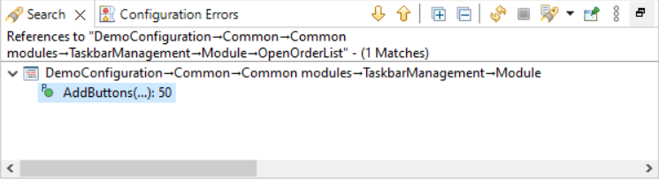
This structure is grouped by configuration objects that initiate specific events and contain particular commands. Just like in the call hierarchy panel, you can double-click to open a procedure or a configuration object displayed in the panel.
Find Event Subscriptions
When analyzing event handlers, it is often necessary to determine whether there are subscriptions to a particular event and what operations they perform. This information can be found in the ER Diagram panel. It has a separate section displaying events that allow subscriptions.
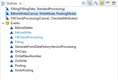
If there are subscriptions to an event, they will be shown under that event’s branch. By double-clicking a subscription, you will open its procedure in the 1C:Enterprise Language Editor. If you then press  on the command bar of Navigator, the configuration object tree will display the object that owns this procedure.
TODO, FIXME, and XXX Tasks
It is rare for algorithms to be written all at once. Most often, development happens in stages, making it important not to forget what needs to be completed and what is planned. The Tasks panel helps with this.
Some tasks are automatically generated by 1C:EDT from comments containing // TODO, // FIXME, and // XXX in module texts. By double-clicking a task, you can jump to the module line containing this comment.
Custom Tasks
You can manually mark module lines as tasks by clicking Add Task... in the context menu of the vertical ruler in the 1C:Enterprise Language Editor.
Advanced Module Analysis
When debugging a module or analyzing deeply nested algorithms, bookmarks in the Bookmarks panel can be helpful.
Bookmarks can be manually placed on important module lines, such as starting points for analyzing nested procedures or marking a location where a question arose during debugging.
To set a bookmark, press Add Bookmark... in the context menu of the vertical ruler in the 1C:Enterprise Language Editor.
To quickly jump to a marked module line, double-click the bookmark in the Bookmarks panel.
Module Quick Outline
The Module Quick Outline allows you to navigate within a module by searching for the required procedures or functions.
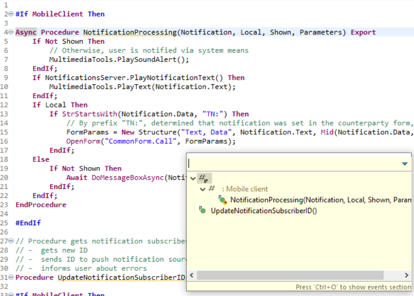
To open the quick ER diagram, press Ctrl+O. All module procedures and functions will be displayed just as they appear in the ER Diagram panel.
Start typing the procedure or function name, and matching elements will be displayed immediately.
Use the up and down arrow keys to select the desired element and press Enter. The cursor will be positioned at the declaration of the selected procedure or function.
Similar actions can be run with the mouse.
If you also need event subscriptions in addition to procedures and functions, you can press Ctrl+O again in the quick ER diagram, and the event branch will be displayed.
ER Diagram Panel
When using with the 1C:Enterprise Language Editor, the ER Diagram panel displays the structure of the module opened in the editor.
Open the ER Diagram Panel
Press Window > Show View > Other... > General > ER Diagram
This connection also works in reverse. When you click a procedure (or directive) in the ER Diagram panel, it is immediately highlighted in the 1C:Enterprise Language Editor (highlighting the procedure name).
Preprocessor directives present in the module are also displayed in the ER Diagram panel. If the module contains regions defined by preprocessor directives, they are displayed in the ER diagram, grouping the methods within them.
Structure of Information in the Panel
The structure includes variables, functions, procedures, and preprocessor directives found in the edited module.
Note: The term methods is used to collectively refer to procedures and functions.
Methods enclosed by preprocessor directives are displayed as subordinate elements of these directives.

A separate branch  displays non-interactive module events and subscriptions related to those events.
Legend
 A regular variable.
 An exported variable.
 A regular method.
 An exported method.
 An event handler, which is a procedure in the 1C:Enterprise language that processes an event.
 An extending method used in configuration modules. It indicates an extending method located in an extension.
 An extending method used in extension modules. It shows that this method extends a method from the original configuration.
 If a method’s usage scope is limited by compilation directives and does not match the context of the entire module, the contexts in which these methods are available are specified.
- Methods enclosed by preprocessor directives are grouped with an indication of the directive and the contexts in which branching occurs.
 Structural elements of the module that are grouped within regions are marked with the region name.
- Events Group
- The Events group contains non-interactive events processed in the module, where a subscription is possible.
- A non-interactive event is processed in the module, where a subscription is possible.
 A non-interactive event is already processed in the module. The name of such an event is highlighted in color.
 A subscription to an event.
Mouse Actions and Dragging
- A single click on a variable or method positions the 1C:Enterprise Language Editor at the declaration of that element if the link with the editor option is enabled.
- A single click on a variable or method while holding Ctrl or Shift selects multiple structural elements in the list for copying, moving, or deleting.
- A double-click on an event subscription opens the event handler of the selected subscription in the 1C:Enterprise Language Editor.
- Dragging structural elements within the panel changes their placement in the module.
- Dragging structural elements within the panel while holding Ctrl copies the content of the selected element to the specified location in the module.
Troubleshooting: Dragging is only possible when structural elements are sorted in the order in which they appear in the module.
Command Bar
- (Collapse All) Collapses all hierarchy levels in the panel down to the first level.
- (Link with Editor) Links the panel with the editor so they function synchronously. The panel automatically highlights the element being edited. Conversely, a single click in the ER Diagram panel positions the 1C:Enterprise Language Editor at the definition of the relevant variable or method.
 (Sort) sets the order in which structural elements are sorted in the panel. If the button is unpressed, structural elements are sorted in the order they appear in the module. If the button is pressed, elements are sorted alphabetically.
 (Show Event Section) shows or hides the branch containing interactive events that can be subscribed to.
Context Menu
- Copy copies the structural elements selected in the panel to the clipboard. These elements can then be pasted into this or another module using the Paste command.
- Paste pastes content from the clipboard into the module using the commands Copy and Cut. The paste operation occurs after the structural element selected in the panel.
- Delete removes the selected structural elements from the module.
- Enclose in #Region wraps selected structural elements of the module with `#Region` ... `#EndRegion` instructions. Grouping elements into a region is only possible when they are adjacent in the module. Before using this command, ensure that structural elements are sorted in the same order as they appear in the module.
- Cut cuts the selected structural elements from the module to the clipboard. These elements can then be pasted into this or another module using the Paste command.
- Create Event Handler this command is active on events from the Events branch. It adds a procedure definition at the end of the module to handle the selected event.
- Find References opens the Search panel and displays the calling hierarchy of methods and configuration objects related to the selected method in the panel.
- Call Hierarchy opens the Call Hierarchy panel and displays the calling or called hierarchy of methods for the selected method.
- Open Event Handler this command is active for subscriptions . It opens the event handler for the selected subscription in the 1C:Enterprise Language Editor.
- Open Extension Element this command is active for extendable methods in the configuration . It opens the extending method in the extension.
- Open Extendable Method this command is active for extendable methods in an extension . It opens the extendable method in the configuration.
- Add to Extension creates a method template extending the selected method and places it in the relevant configuration extension module.
Call Hierarchy Panel
The Call Hierarchy panel displays the calling or called hierarchy of procedures and functions, hereafter referred to as methods, in relation to the method where the command was executed Call Hierarchy. This command is available in:
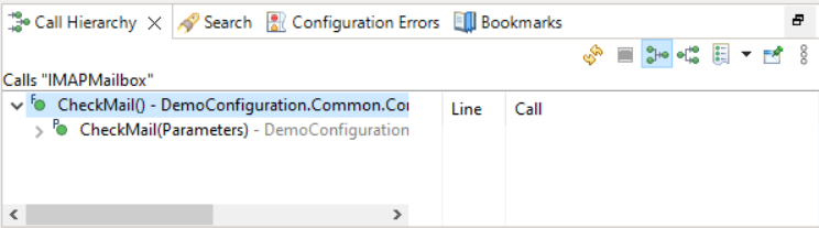
This panel opens automatically when the command is executed. It can also be opened manually from the main menu of the main window by selecting Window > Show View > Other… > 1C:Enterprise > Call Hierarchy.
Structure of Information in the Panel
At the first level of the hierarchy, the method under analysis is displayed. Deeper levels show methods corresponding to the execution sequence of the program code.
In a calling hierarchy  (upward), deeper levels display methods from which the analyzed method is called. When such methods are selected, 1C:EDT displays their corresponding lines in columns Line and Call, indicating where the "parent" method is called.
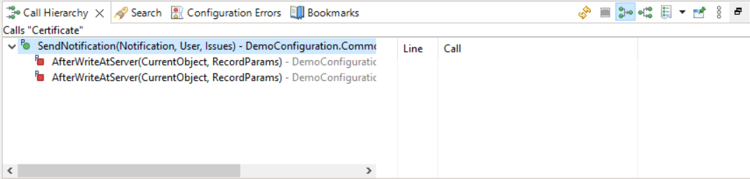
In this example, from the procedure BeforeWrite() in the document module Order, the method CurrentUser() in the common module Users is called. This call occurs at line 31 of the document module Order as a result of executing the statement Users.CurrentUser().
Important: If a calling hierarchy (upward) is constructed, the lines from the highlighted module are displayed on the right.
In a called hierarchy  (downward), deeper levels show methods that are invoked by the analyzed method. When such methods are selected, columns Line and Call display the lines of the "parent" method where these methods are called.
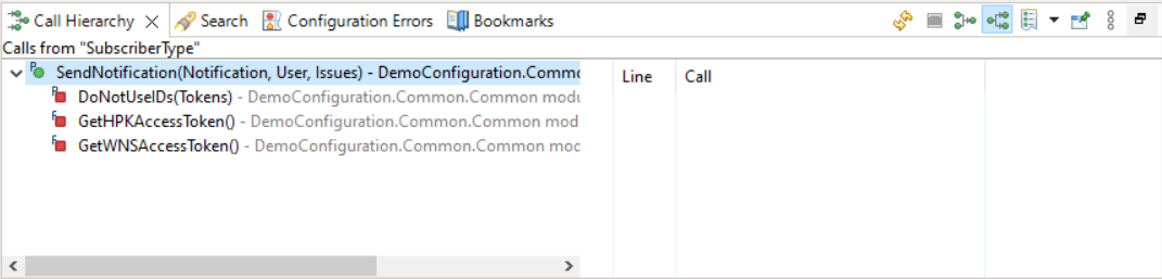
In this example, from the method OnStart() in the application module, the method OnStart() in the common module ClientHelper is called. This call occurs at line 15 of the application module as a result of executing the statement ClientHelper.OnSystemStart().
Important: If a called hierarchy (downward) is constructed, the lines displayed on the right belong to the "parent" rather than the highlighted module.
Legend
 Regular procedure.
 Regular function.
 Exported procedure.
 Exported function.
 Possible method call. The type-building system did not determine it, but a call with a matching identifier (procedure or function name) was found in this module.
 In a calling hierarchy (upward), the number of lines in this module where the "parent" method is called is indicated in parentheses. In a called hierarchy (downward), the number of lines in the "parent" method where this method is called is indicated in parentheses.
Columns
- The first column displays the method hierarchy corresponding to the selected type of analysis (more details).
- Line shows the line number in the module where the call occurs. This column can be hidden.
- Call displays the 1C:Enterprise language operator executing the call. This column can be hidden.
Mouse Actions
- A single click in the first column displays calls in columns Line and Call (more details).
- A double-click in the first column in 1C:Enterprise Language Editor opens the module that contains the calls and places the cursor on the first one (learn more).
- A double-click in column Line or Call in 1C:Enterprise Language Editor opens the module that contains the call and places the cursor on that line in the module (learn more).
Command Bar
- (Refresh) Updates the information in the panel.
 (Cancel Current Search) interrupts the call hierarchy construction operation.
 (Show Calling Hierarchy) When pressed, indicates that the panel displays the calling hierarchy of methods. Pressing this button clears the panel and builds the calling hierarchy of methods.
 (Show Called Hierarchy) When pressed, indicates that the panel displays the called hierarchy of methods. Pressing this button clears the panel and builds the called hierarchy of methods.
 (Clear History List) The drop-down list shows the history of building the call hierarchy for different methods. The method currently displaying the call hierarchy is marked with a dot
  . Clicking any other method in this list displays the call hierarchy that was built for it in the panel. The Clear History command clears this list and the Call Hierarchy panel.
- (Pin Panel) Pin Panel. If this button is pressed, the panel will not be closed by other panels in its group.
- (Show Menu) Opens a drop-down menu containing additional commands for the panel.
- Calling Hierarchy When pressed, indicates that the panel displays the calling hierarchy of methods. Pressing this button clears the panel and builds the calling hierarchy of methods.
- Called Hierarchy When pressed, indicates that the panel displays the called hierarchy of methods. Pressing this button clears the panel and builds the called hierarchy of methods.
- Position submenu contains the following commands:
- Horizontal Displays columns Line and Call in the panel.
- Hierarchy Only hides columns Line and Call.
Context Menu of the First Column
- Remove from View removes the selected row with all its descendants from the panel.
- Refresh updates the information in the panel.
- Open in 1C:Enterprise Language Editor opens the module that contains the calls and places the cursor on the first one (learn more).
- Show Call Hierarchy for the Current Element clears the panel and displays the calling or called hierarchy of methods in relation to the selected method.
- Find References opens the Search panel and displays the calling hierarchy of methods and configuration objects related to the selected method in the panel.
Context Menu of Columns
- Open in 1C:Enterprise Language Editor opens the module that contains the call and places the cursor on that line in the module (learn more).
- Show Call Hierarchy for the Current Element clears the panel and displays the calling or called hierarchy of methods in relation to the selected method.
- Find References opens the Search panel and displays the calling hierarchy of methods and configuration objects related to the selected method in the panel.
Bookmarks Panel
Panel Bookmarks displays all bookmarks created in modules during editing.
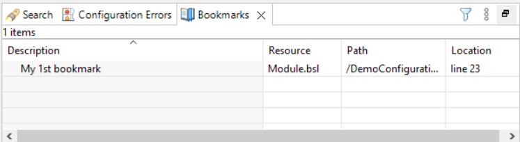
This panel can be opened from the main menu of the main window by selecting Window > Show View > Other… > General > Bookmarks.
This panel is populated as bookmarks are added to modules.
Columns
- Description displays the bookmark description. By default, 1C:EDT uses the text of the line where the bookmark is set as the description. You can modify the bookmark description directly in the table or in an individual dialog.
- Files shows the name of the file where the bookmark is set.
- Path displays the path to the file where the bookmark is set.
- Location indicates the line number where the bookmark is set.
Mouse Actions
- A single click in the Description column allows modifying the bookmark description.
- A single click while holding Ctrl or Shift selects multiple rows in the list for copying or deleting.
- A single click on the column header sorts the table by that column. If the table is already sorted by that column, the sort direction changes.
- A double-click on a row in the table opens the module in the 1C:Enterprise Language Editor and positions the cursor on the line containing the selected bookmark.
Command Bar
- (Filters) Opens a dialog that allows you to display only specific bookmarks instead of all. Filtering by project association and description is available. You can also limit the number of displayed bookmarks.
- (Show Menu) Opens a drop-down menu containing additional commands for the panel.
- Sort By submenu contains the following commands:
- Description Sorts the list by column Description.
- Files Sorts the list by column Files.
- Path Sorts the list by column Path.
- Location Sorts the list by column Location.
- New Bookmark Panel Opens another bookmark panel.
- Filters... Opens a dialog that allows you to display only specific bookmarks instead of all. Filtering by project association and description is available. You can also limit the number of displayed bookmarks.
- Column Settings... Opens a dialog that allows you to configure the composition, order, and width of the list columns.
Context Menu
- Go to Resource Opens the module in the 1C:Enterprise Language Editor and positions the cursor on the line containing the selected bookmark.
- Copy Copies the names of columns and values of fields of the selected bookmark to the clipboard.
- Copy Details submenu contains the following commands:
- Description Copies the bookmark description to the clipboard.
- Full Resource Name Copies the values of fields Path and Files to the clipboard.
- Delete Deletes selected bookmarks.
- Select All Selects all bookmarks in the list.
- Show In submenu contains the following commands:
- Explorer Displays the file associated with the bookmark in Explorer.
- Properties Displays bookmark properties in the Properties panel.
- Edit Description Opens a dialog that allows you to edit bookmark descriptions.
Search Panel
Highlight the Current Identifier
You can enable the mode for highlighting the current identifier. When this mode is active, 1C:EDT automatically highlights all instances of the identifier under the cursor in the 1C:Enterprise Language Editor.
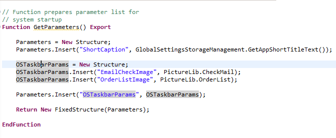
To enable this mode, click ![]() (Toggle Occurrence Markers) in the Main Window Command Bar.
(Toggle Occurrence Markers) in the Main Window Command Bar.
You can select the method 1C:EDT will use to find the highlighted fragments. The options include either simple string representation matching or considering the type of the current identifier as determined by the 1C:Enterprise language’s type system.
To choose the highlighting method, click Window > Preferences > V8 > 1C:Enterprise language > Highlighting the Current Identifier.
Search Panel
The results displayed in the Search panel vary in appearance depending on the operation run.
If you perform a method reference search, the panel displays a list of modules and configuration objects that call the original procedure or function (referred to as a method).
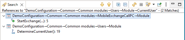
Structure of Information in the Panel
The list is grouped by module, and for each module, all methods that call the analyzed method are listed along with the line number of the call. If the method is called multiple times from the same source, each call appears separately with its respective line number.
If the original method is an event handler for a form or its elements, the form appears at the first level, and the second level shows the form item for which the method is assigned as an event handler.
Legend
 Regular procedure.
 Regular function.
 Exported procedure.
 Exported function.
 Possible method call. The type system did not determine it, but this module contains a call with a matching identifier (procedure or function name).
Mouse Actions
- A single click while holding Ctrl or Shift selects multiple lines for deletion.
- A double-click on a found element opens the module in the 1C:Enterprise Language Editor and navigates to the respective line.
Command Bar
- (Show Next Match) highlights the next found element in the list and opens it in the relevant editor. If it is a module, it positions on the found line.
- (Show Previous Match) highlights the previous found element in the list and opens it in the relevant editor. If it is a module, it positions on the found line.
 (Expand All) Expands all hierarchy levels in the panel.
- (Collapse All) Collapses all hierarchy levels in the panel down to the first level.
- (Refresh) Updates the information in the panel.
- (Cancel Current Search) interrupts the search operation.
- (Show Previous Searches) the drop-down list displays the search history. The current search is marked with a dot . Clicking any other search from the list displays its results in the panel. The History... command allows deleting unnecessary searches and setting the number of stored searches. The Clear History command clears this list and the panel Search.
- (Pin Panel) If this button is pressed, the panel will not be closed by other panels in its group.
- (Show Menu) Opens a drop-down menu containing additional commands for the panel.
Context Menu
- Copy copies the selected element to the clipboard.
- Delete Selected Matches deletes selected rows and their descendants from the panel.
Parameter Group: Highlighting the Current Identifier
This parameter group allows you to configure how the current identifier is highlighted and also reset the Remember Selection settings.
To open this group, click Window > Preferences > V8 > 1C:Enterprise language > Highlighting the Current Identifier.
Field Descriptions
- Search Strategy for Identical Elements
- Based on the 1C:Enterprise language model: Highlights identifiers in the module that match both the string representation and type of the identifier under the cursor.
- By string representation match: Highlights all identifiers in the module that have the same string representation as the identifier under the cursor.
Context Hint
Context hints are a tool that helps write and edit program text. They facilitate faster input and help avoid errors and typos.
Context hints display only the properties, methods, and objects available in the current editing context.
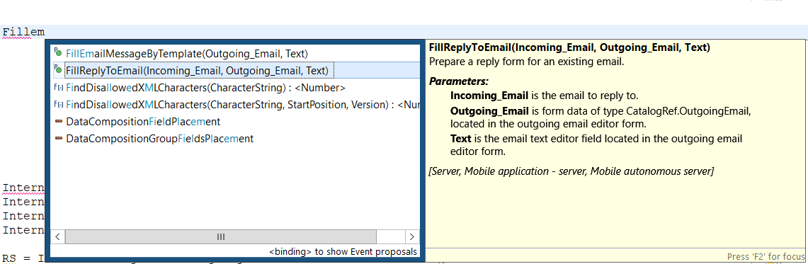
On the right side of the syntax list, a reference section appears for the selected element.
Pressing Enter inserts the selected syntax structure into the text.
This tool functions similarly to the context hints available in 1C:Enterprise Designer. More details can be found in 1C:Enterprise documentation.
Automatic Hints
Context hints open automatically after typing a period, which indicates a call to an object’s method or property.
They also activate automatically when entering a comma in a method’s parameter list.
Manually Opening Hints for a Property or Method
Context hints can be triggered manually if they were accidentally closed.
For example, if a property name was being entered but not completed, and moving the cursor caused the hint to disappear, In this case, you can:
-
Place the cursor after the entered portion of the property.
-
Press Ctrl+Space to open the context hint.
-
Continue entering the text.
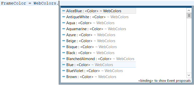
Another case where manual hint activation may be necessary is when replacing one property with another. For example, if "Blue" was entered in a module but needs to be changed to a different color, In this case, you can:
-
Select the property that needs to be replaced.
-
Press Ctrl+Space to open the context hint.
-
Choose a different value.
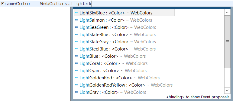
Event Handlers and Text Templates
Context hints have a second page, which can be accessed by pressing Ctrl+Space again. This page displays a list of available event handlers and text templates that can be inserted into the module.
Manually Opening Hints for a Method Parameter
If a context hint is closed while entering method parameters, it can be reopened manually.
-
Place the cursor where the desired parameter is located.
-
Press Ctrl+Shift+Space to open the context hint.
-
Continue entering the text.
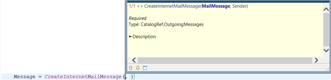
Techniques for Using Context Hints
Several techniques can enhance the efficiency of using context hints in modules.
-
The hint list begins with elements that start with the entered text, followed by elements that contain the text within them. For example, if you need a list of objects related to XDTO, you can simply type that word in the editor and then select the desired item from the list.
-
The hint list can be further refined by using abbreviations when entering identifiers. For example, in a form module, typing
GetObFormwill limit the list of suggestions to the following methods: GetCommonFormGetObjectAndFormAttributeConformity() and GetObjectAndFormConformity(). -
It is also possible to simplify the name of the desired element even further by entering only the first uppercase letters of each word. For example, if you want to write
NewUniqueID()., you can typeNewfollowed byUI. Then, in the context hint window, UniqueID() will appear at the top of the list.
Key Hints for Structures Returned by a Function
If the returned structure is described in a documenting comment, the context hint will provide suggestions for its fields when accessed through the dot operator outside the method.
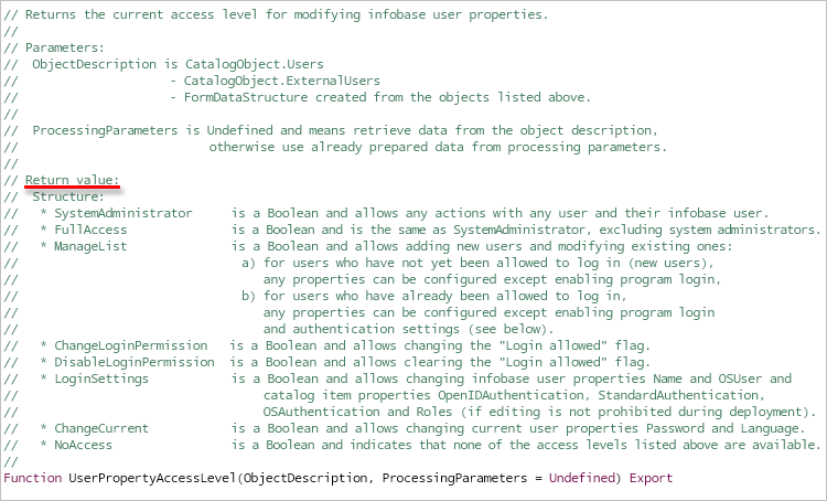
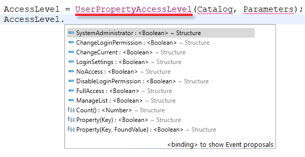
Key Hints for Structures Used as Parameters
If a function parameter is a structure and is described in a documenting comment, the context hint will provide suggestions for its fields via the dot operator inside the function.
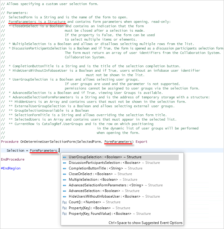
1C:Enterprise Language Templates
About Templates
Templates are predefined fragments of 1C:Enterprise language text that can be used when writing modules.
There are two types of templates:
-
Standard Templates
 are a fixed set of templates stored in 1C:EDT. These templates can be used but cannot be modified or deleted.
 -
User Templates
 can be imported, edited, deleted, or newly created.
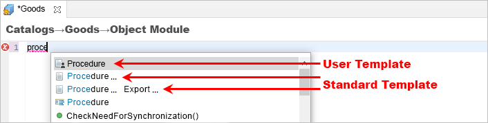
1C:EDT Templates and Project Templates
User templates can be stored in two locations:
-
In the workspace, allowing the same set of templates to be used across multiple projects.
-
In the project, making the templates available to the entire development team working on that project.
Contexts
Each template must have an assigned execution context. When invoking the context hint, only the templates relevant to the current module context appear.
Variables
A template can contain variables that perform specific actions when inserted or after insertion into a module.
For example, the following template uses two variables: $\{Edit()\} and $\{TypeChoice()\}.
If TypeOf(${Edit()}) = Type("${SelectType()}") Then

    ${Edit()}

EndIf.
After inserting the template into the module, variables are replaced with markers (arrows indicate markers).

In the first marker, you can enter text. When moving to the second marker, 1C:EDT opens a type selection dialog.
Insert a Template into a Module
Templates can be inserted into modules using the context hint by pressing Ctrl+Space.
On the first page of the context hint, 1C:EDT suggests templates that contain the entered text in their name.
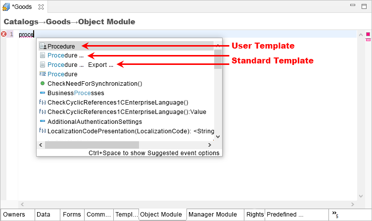
On the second page of the context hint (pressing Ctrl+Space again), all user templates and available event handlers appear.
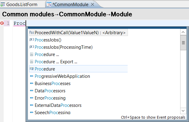
1C:Enterprise language templates may contain variables. After inserting a template into a module, variables are replaced with markers. For example, the following template:
If TypeOf(${Edit()}) = Type("${SelectType()}") Then

    ${Edit()}

EndIf.
After insertion, the template appears as follows (arrows indicate markers).
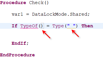
You can navigate between markers by pressing Tab and Shift+Tab. In the first marker, you can enter text. When moving to the second marker, 1C:EDT opens a type selection dialog.
Add, Export, Import Templates
To add, edit, or delete templates, open one of the template lists.
Open the List of User Templates
- To open the list of templates in the workspace, click Window > Preferences > V8 > 1C:Enterprise Language > Templates in the Main Window Command Bar.
- To open the list of templates in the project, click Navigator, then select Properties > V8 > 1C:Enterprise Language > Templates from the project's context menu.
In both cases, the template list looks the same and provides identical functionality.
Add a Template
- Open the template list.
- Click Add....
- In the Name field, enter the template name. The name is for reference and helps distinguish one template from another. The template name must be unique within its list. However, templates in different lists can have identical names. In this case, the project template takes priority.
- Select the context for the template.
All contexts are enabled by default for a new template.
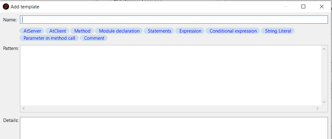
You can disable some contexts to limit the templates suggested when editing different module parts.
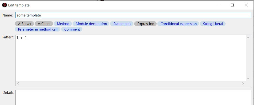
At least one of the contexts AtServer or AtClient (or both) must be selected, along with one or more additional contexts. Example:
-
AtServer, Method refers to usage inside server-side methods.
-
AtServer, AtClient, Expression applies inside any expressions. The available contexts include:
-
AtServer indicates the server execution context for the 1C:Enterprise language (details).
-
AtClient indicates the client execution context for the 1C:Enterprise language (details).
-
Method is used inside a procedure or function.
-
Module Declaration applies outside procedures and functions, in the variable declaration section or the main program section (details).
-
Operator applies where an assignment operator can be written.
-
Expression applies inside an expression, such as to the right of an assignment operator, in parameters, or in conditions.
-
Conditional Expression applies in the conditions of If and While statements.
-
String Literal applies inside a string literal.
-
Parameter in Method Call applies when entering procedure and function parameters.
-
Comment applies inside comments.
- Enter the template text.
Variables can be inserted using the context hint mechanism, which is activated by pressing Ctrl+Space. Each variable’s purpose is described in the hint.
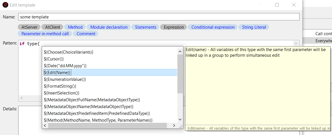
Once a variable is inserted into the template, you can navigate its parameters by pressing Tab and Shift+Tab. For parameters with predefined values, a selection list will be offered.
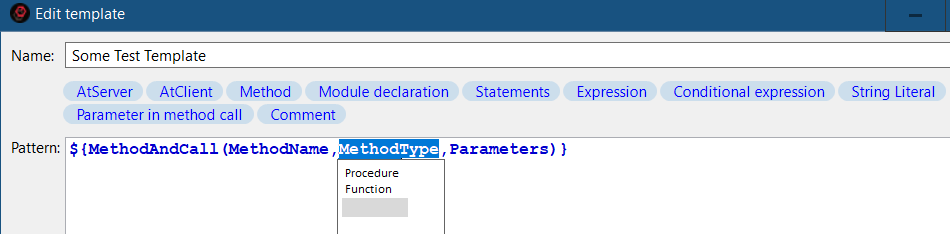
- Enter a description for the template. This description appears in the context hint when inserting the template into a module.
- Click OK.
- If necessary, add additional templates the same way.
- Click Apply and Close to save all parameter changes.
Import Templates
1C:Enterprise templates can be imported from an .st file. For example, if you created custom templates for the platform, they will automatically be converted to the 1C:EDT template format.
1C:EDT templates can be imported from a .txt file. These templates may have been exported from another project or received from another developer.
To import templates, follow these steps:
- Open the template list.
- Click Import....
- Select the template file and click Open.
- Edit template names if conflicts occur.
- Click OK.
- Click Apply and Close to save the template list.
Export Templates
Templates can be exported to a .txt file. To do this:
-
Open the template list.
-
Hold Ctrl and select the templates you want to export with the mouse (press Ctrl+A to select all).
-
Click Export....
-
Select the directory where you want to save the file and enter the file name with the extension.
-
Click Save.
Importing "Old" Templates
If you have created 1C:Enterprise language templates in 1C:EDT versions earlier than 2021.2, you can automatically convert them to the new format.
Templates in the old format are stored in the workspace. To convert them, open the old workspace in a newer version of 1C:EDT, 2021.2 or later. Templates will be converted automatically, and you will see them in the template list.
Examples of Using Variables
TypeChoice
The variable $\{TypeChoice()\} is useful when you need to specify the type of a value.
For example, a template may look like this:
If TypeOf(${Edit("Expression to validate type")}) = Type("${TypeChoice()}") Then

    ${Edit("")}

EndIf.
After inserting this template and entering the variable name, 1C:EDT will open a type selection window where you can find the required type using a search field.
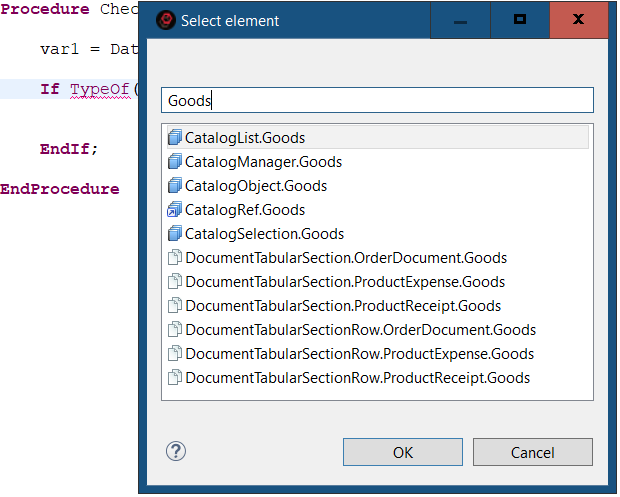
As a result, the code fragment will appear as follows:
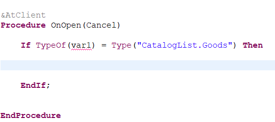
Select
The variable $\{Select()\} allows selecting one of the listed values. For example, when using the OpenForm operator, you need to specify the type of form to open or a specific form name. This selection is limited to predefined values, which can be listed in the variable $\{Select()\}.
After inserting the following template into a module and selecting a document, it will prompt you to choose one of the available form types.
OpenForm("Document.${MetadataObjectName(Document)}.${Select("ObjectForm", "ListForm", "ChoiceForm", "Form.")}${Edit("")}").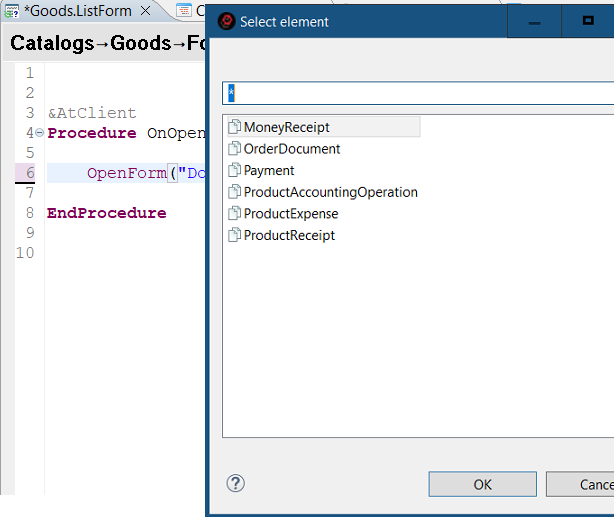
This will generate the form name.
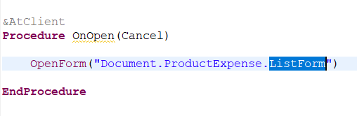
EnumValue
The variable $\{EnumValue()\} is useful for selecting a predefined value on the client side.
After inserting the following template into a module, it will open a selection window where you can find the required enumeration type or value using a search field.
PredefinedValue("Enumeration.${EnumValue()}")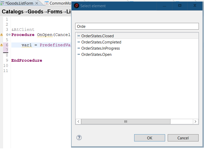
As a result, the code fragment will appear accordingly.
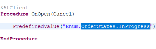
MetadataObjectName
The variable $\{MetadataObjectName()\} allows selecting the name of a configuration object, its attribute, a tabular section, or other subordinate objects. For example, when using the OpenForm operator, you need to specify the name of the configuration object whose form should be opened.
After inserting the following template into a module, it will prompt you to select one of the documents available in the configuration.
OpenForm("Document.${MetadataObjectName(Document)}.${Select("ObjectForm", "ListForm", "ChoiceForm", "Form.")}${Edit("")}").
This will generate the form name.
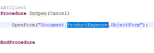
Method
The variable $\{Method()\} can be used, for example, to insert an event description.
The following template adds a placeholder for describing an event in a module.
Notification = New EventDescription("${Method(Handler,
Procedure)}", ThisObject).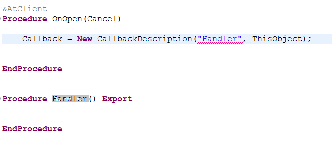
MethodAndCall
The variable $\{MethodAndCall()\} is useful, for example, when creating a template that sums the results of two functions.
${Edit(SumFunctions)} = ${MethodAndCall(FirstFunction, Function, Param1)} + ${MethodAndCall(SecondFunction, Function, Param2)}.For instance, this template can be inserted into the following procedure.
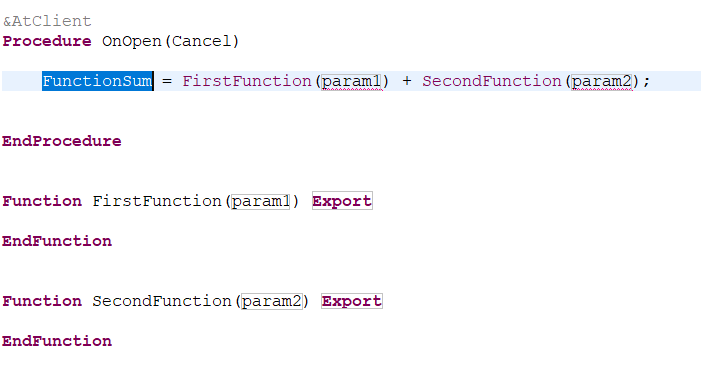
As a result, an assignment operator will be inserted inside the procedure, while two functions will be created outside the procedure.
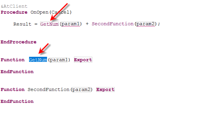
When navigating between placeholders, 1C:EDT will suggest choosing one of the available contexts in which each function will be executed.
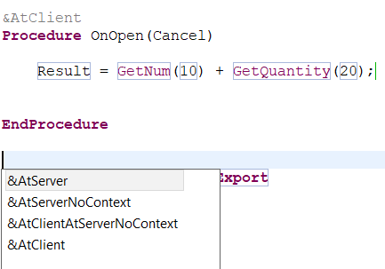
Additionally, 1C:EDT will suggest using the modifier Async.
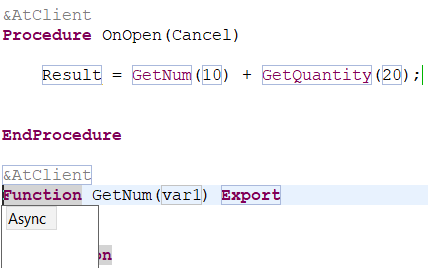
The second parameter of the variable determines which method will be created: Function or Procedure. Accordingly, if a procedure call needs to be inserted, the template may look like this:
${MethodAndCall(MyProcedure, Procedure, param1, param2)}.As a result, a procedure and its call will be added to the module.
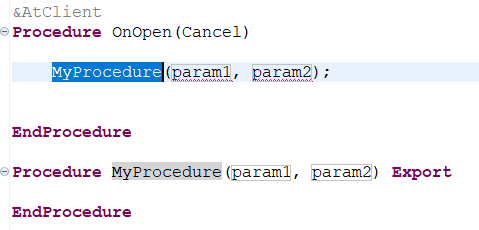
Edit
The following template demonstrates the usage of the variable $\{Edit()\}:
Procedure ${Edit("Procedure Name")}()

    ${Edit("")}

EndProcedure // ${Edit("Procedure Name")}()
The value of the parameter Procedure Name serves two purposes. First, it acts as an input hint, appearing in the marker after inserting the template.
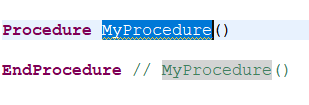
Second, markers associated with variables that share the same parameter value are linked. When text is entered in one of these markers, it is automatically reflected in the other marker.
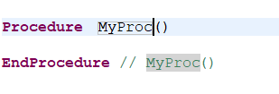
A variable without a parameter simply acts as a placeholder for where the cursor should be placed for text input.
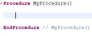
FormatString
The variable $\{FormatString()\} is useful when specifying formatting parameters for a value.
For example, the following template inserts the Format statement and opens a dialog for creating a format string.
Format(${Edit("")}, "${FormatString()}")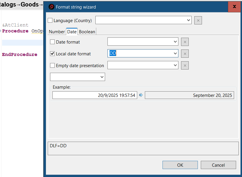
The result may look like this.
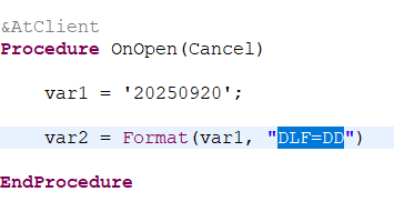
Refactoring
Rename Variable or Method
-
Place the cursor on the variable or method name that needs to be renamed.
-
Click Refactoring > Rename... in the context menu.
-
Change the highlighted name to the required one.
-
Press Enter.
If desired, before performing refactoring, you can review the changes that will be made to the code. To do this, after step 3, click Preview... in the suggestion dropdown.
In the preview window, you can see all proposed changes and reject some by unchecking them in the upper window.
Extracting Local Variable
An expression that is used multiple times in a module can be replaced with a variable. This makes the text simpler and more "readable" and helps prevent errors if you decide to modify the expression. You will not need to change it in every occurrence—just modify it in one place where it is assigned to the variable.
This need may arise not only when "tidying up" an already written module but also while writing it. For example, you may find that you need to use an expression again that you have already used earlier.
In this case, you can highlight the expression and click Refactoring Extract Local Variable... in the context menu.
1C:EDT will prompt you to name the variable in which this expression will be placed and will automatically suggest replacing all occurrences of the expression.
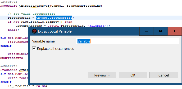
You can agree and click OK.
If you are unsure, click Preview to see how the module will change after performing this operation.
After clicking OK, the expression will be extracted into a variable.
Extract Method
An expression that is used multiple times in a module can be replaced with a function call. This not only makes the text more "readable" but also allows you to use the expression in different procedures within the module and even in other modules.
This need may arise while writing the program text. For example, you may find that you need to run the same algorithm again, which you already described in another procedure or module.
In this case, you can highlight the algorithm fragment and click Refactoring Extract Method... in the context menu.
1C:EDT will prompt you to name the function in which this fragment will be placed. If you need the result of this function in other modules, you can immediately check the box for Export Method.
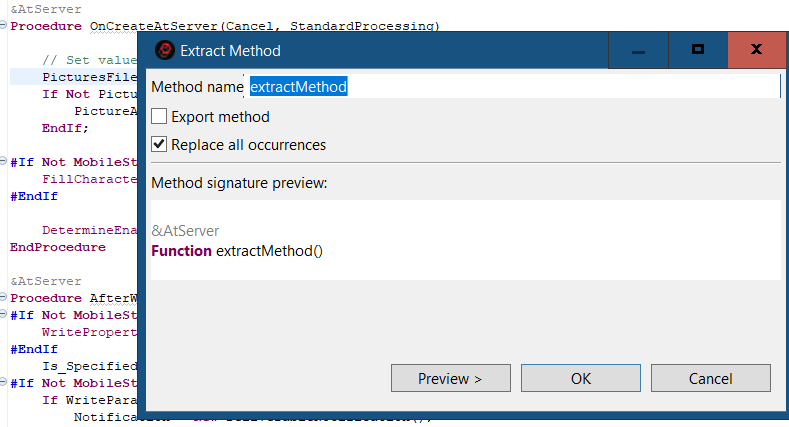
Before clicking OK, you can review how the module will change. To do this, click Preview.
After clicking OK, the algorithm fragment will be extracted into a function.
Rename Metadata
If you decide to rename a configuration object or its attribute, after making changes, 1C:EDT will perform a full search of all occurrences of this attribute within the configuration structure, program module texts, query texts, and so on. It will use full-text search.
The planned changes to the configuration will be displayed in the refactoring dialog.
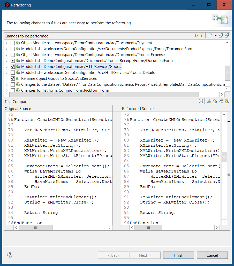
All changes are grouped by configuration objects, and for the currently selected row, a comparison of modules (lines) before and after the changes is immediately shown.
You can review all changes that 1C:EDT plans to make to the project and reject some of them if necessary.
Rearrange Module Fragments
Using the ER Diagram panel, you can edit modules in entire fragments:
-
Perform actions on one procedure or multiple procedures at once by selecting them with the mouse while holding Ctrl or Shift.
-
Drag and drop procedures with the mouse (sorting must be disabled for this to work).
-
Copy procedures by holding Ctrl while dragging with the mouse or using context menu commands.
-
Copy procedures between different modules and different application solutions by clicking Copy in one module's ER diagram and Paste in another module's ER diagram.
Syntax Assistance
Popup Syntax Hint
The syntax hint opens automatically when you hover the mouse cursor over any identifier used in the text.
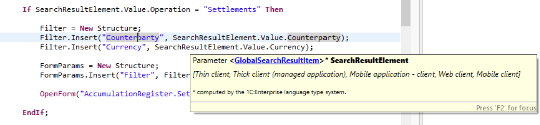
This hint applies not only to types defined in the platform, but also to your own procedures and functions... These comments are easiest to create using the Source Generate Method Comments context menu command in the 1C:Enterprise Language Editor.
Syntax Help in the Context Hint
Syntax help is automatically shown in the context hint while editing configuration modules.
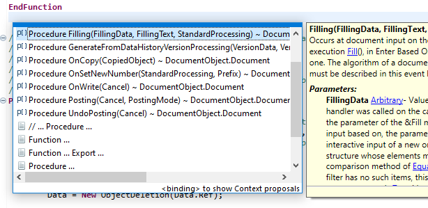
Syntax Assistant Panel
The Syntax Assistant panel operates together with the 1C:Enterprise Language Editor.
It provides real-time hints for types, events, methods, and properties of the 1C:Enterprise language. This panel is synchronized with the 1C:Enterprise Language Editor and displays hints for the identifier where the editor's cursor is positioned.
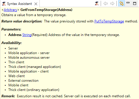
This panel is part of the standard perspectives of 1C:Enterprise.
Open Syntax Assistant Panel
Press Window > Show View > Other… > 1C:Enterprise > Syntax Assistant.
The panel is filled with data automatically if linking with the editor is enabled. 1C:EDT analyzes the current identifier under the cursor in the 1C:Enterprise Language Editor and, if a syntax hint is available, it displays it.
Command Bar
 (Additional Guidance) opens a browser window with links to additional information explaining the use of the selected property, method, or object described in the Syntax Assistant panel.
 (Back) navigates back through the viewing history in the Syntax Assistant panel.
 (Forward) moves forward in the browsing history in the Syntax Assistant panel.
- (Link with Editor) Link with Editor links the panel with the editor so they function synchronously. The panel automatically highlights the element being edited.
Additional Guidance
If the available information is insufficient, in the Syntax Assistant panel, you can press (Additional Guidance) to open a list of internet links related to the given object, type, or property.
On-the-Fly Configuration Validation
1C:EDT checks the configuration structure and module texts on the fly. This validation is performed automatically when 1C:EDT starts and the project model is built. While editing modules or modifying the configuration tree structure, validation is also performed immediately.
There are standard validations created by the 1C:EDT development team. Additionally, you can add user-defined validations, implemented as 1C:EDT plugins.
Displaying Validation Results
If an issue is detected during the validation, 1C:EDT displays markers (such as errors  and warnings ) in a way that makes them noticeable while allowing you to review and correct them.
To ensure warnings are not overlooked, problematic configuration elements are marked with special icons directly in the configuration tree. The object itself (such as an attribute) and all its parent elements are marked. If child elements have different levels of severity, the parent is marked with the highest severity among its children.
Similar markings appear in the configuration object editor—on its title, on tabs containing problematic elements, and on the elements themselves.
In modules, warning and error icons appear on the left in the vertical ruler. On the right, in the overview ruler, all module lines with errors are highlighted. Clicking on a marker allows you to quickly navigate to any of them.
This way, you always see potential problems if they exist. Hovering over a marker provides a description of the issue or error found by the validation mechanism.
Fixing Errors
Reviewing problems and errors found by the validation mechanism can be an individual process. It runs after editing rather than during it. Since manually searching for special marks throughout the configuration is inconvenient, all errors and warnings are displayed in the Configuration Errors panel as a list. Here, you can review them one by one, and by double-clicking an error, you can immediately jump to the relevant module line or editor tab where the problematic value is edited.
Validation Settings
Validations can be managed (enabled or disabled for the entire configuration). This allows you to tailor the validations to the specific development process of a team or project. You can also create multiple validation profiles to be used at different development stages. All validation settings are stored in the project, ensuring portability for collaborative development and project transfers.
Important: The option to manage standard validations was implemented in version 2021.2. At this point, only some of the standard 1C:EDT validations have been migrated to the new mechanism. These checks can be viewed in the validation settings dialog and in the Validation Suppression Editor. The remaining standard validations are still run but cannot be managed. Over time, all standard validations will be migrated to the new mechanism.
Suppressing Validations
Enabled validations can be suppressed for individual subsystems, configuration objects, forms, modules, procedures, etc. This way, the validation is not disabled entirely but is skipped in certain configuration parts. This is often needed when developing library solutions where some deviations from coding standards are intentional to ensure proper componentization.
User-Defined Validations
You can create user-defined validations and add them to the standard ones. Each custom validation is a plugin that must be developed in the Eclipse environment for 1C:EDT plugin development. This environment can be installed using 1C:EDT Start (see project type selection here).
Examples of developing user-defined validations can be found in the plugin development documentation.
Validation Settings
Open Validation Settings
In the Navigator panel, click Properties > V8 > Validation in the project context menu.
All settings are stored within the project, ensuring portability, for example, in collaborative development and when moving projects.
The left pane displays a list of configuration validations grouped by category. The upper right section shows the description of the selected validation. The lower right section displays the severity of the selected validation and its configurable parameters, which you can adjust.
Additionally, the lower right section displays the validation code. This validation code may be required for language-based validation suppression and is used in the comment // @skip-check.
Modify Validation Parameters
Enabling and Disabling Validations
- Open the validation settings.
- Check or uncheck a validation or a validation group.
If the checkbox is selected, the validation runs (all validations within the group run).
If the checkbox is cleared, the validation does not run (all validations within the group are disabled).
Severity
- Open the validation settings.
- Select a validation or a validation group and choose the severity level from the dropdown next to the validation code.
By default, all validations have a severity of Minor. Severity levels are used for grouping and filtering errors in the Configuration Errors panel.
Unused Methods Validation: Parameter Settings
The standard Unused Methods Validation (module-unused-method) has additional configuration parameters.
- Excluded Method Name Pattern defines methods that will be excluded from validation.
- Excluded Object Name Pattern specifies configuration object modules that will be excluded from validation. The fully qualified name of the owning object is analyzed. For example:
- Catalog.Products excludes the object module and manager module for the catalog Products.
- CommonModule.MailOperations excludes the common module MailOperations.
- Configuration excludes the application, session, and external connection modules.
- Catalog.Products.Form.ItemForm excludes the form module ItemForm of the catalog Products.
Tip:
The name pattern is specified in the standard Java regular expression format (learn more). In most cases, a few simple patterns are sufficient. For example:
- AtServer ends with the substring AtServer (for example,
OnCreateAtServer,RecalcAtServer). - Fill starts with the substring Fill (for example,
Filling,FillCheckProcessing). - Get*Letters means that the asterisk (
*) represents any number of characters between the substring Get and the substring Letters (for example,GetLetters,GetNewLetters). - Write???ToString means that the question mark (
?) represents any single character (for example,WriteXMLToString,WriteDOMToString).
Validation of Empty Methods: Parameter Settings
The standard Validation of Empty Methods (module-empty-method) has additional configuration parameters.
- Consider Method Comments: true means a method with an empty body but containing comments will not trigger an error, while false means a method with an empty body will always trigger an error.
- Excluded Method Name Pattern defines methods that will be excluded from validation.
- Excluded Object Name Pattern specifies configuration object modules that will be excluded from validation. The fully qualified name of the owning object is analyzed. For example:
- Catalog.Products excludes the object module and manager module for the catalog Products.
- CommonModule.MailOperations excludes the common module MailOperations.
- Configuration excludes the application, session, and external connection modules.
- Catalog.Products.Form.ItemForm excludes the form module ItemForm of the catalog Products.
Tip:
The name pattern is specified in the standard Java regular expression format (learn more). In most cases, a few simple patterns are sufficient. For example:
- AtServer ends with the substring AtServer (for example,
OnCreateAtServer,RecalcAtServer). - Fill starts with the substring Fill (for example,
Filling,FillCheckProcessing). - Get*Letters means that the asterisk (
*) represents any number of characters between the substring Get and the substring Letters (for example,GetLetters,GetNewLetters). - Write???ToString means that the question mark (
?) represents any single character (for example,WriteXMLToString,WriteDOMToString).
Adding a New Validation Profile
1C:EDT always includes a default validation profile. You can add any number of new profiles and use them at different stages of development.
New profiles are added by duplicating a selected profile and modifying its settings.
-
Open the validation settings.
-
In the Validation Profiles field, select the profile to be copied.
-
Click Duplicate Profile.
-
Enter the name for the new profile.
-
Enable or disable the necessary validations.
-
Click Apply or Apply and Close.
Run Validation Manually
When developing user-defined configuration validations (details), you may need to see how your validation functions. Normally, 1C:EDT automatically runs configuration validation while editing configuration objects or modules.
However, if the configuration itself has not changed but the validation code has, you can manually start configuration validation. To enable this option, follow these steps:
-
Open the developer parameter group for the project.
-
Select the checkbox Enable Forced Validation Mode.
-
Click Apply and Close.
After this, a new command Run Validation will appear in the Navigator panel. It will be available in the context menu of the project, configuration, and configuration objects. This command allows you to start validation and view its results.
Hide Results of Validations Running on the Legacy Mechanism
Important: The option to manage standard validations was implemented in version 2021.2. At this point, only some of the standard 1C:EDT validations have been migrated to the new mechanism. These checks can be viewed in the validation settings dialog and in the Validation Suppression Editor. The remaining standard validations are still run but cannot be managed. Over time, all standard validations will be migrated to the new mechanism.
When developing user-defined configuration validations (details), you may need to view only the results of validations using the new mechanism, avoiding clutter in a potentially long error list.
To hide validation results that use the legacy mechanism, follow these steps:
-
Open the developer parameter group for the project.
-
Select the checkbox Hide Results of Outdated Validations.
-
Click Apply and Close.
Hide Language Errors of the Main Branch
Large projects may contain a significant number of inherited errors that do not affect the application's functionality but mainly involve violations of coding standards.
When working on a task, usually done in a separate branch, you can hide errors from the main branch to see only your own errors introduced in the current branch.
Troubleshooting: The following scenario only hides errors related to 1C:Enterprise language. Errors related to metadata structure will remain visible.
For example, you are in the master branch and plan to start working on task issue-45:
-
Create a new branch issue-45.
-
In the Navigator panel, click Properties > V8 > Validation > Settings for Validation Developers in the project's context menu.
-
Enable the checkbox Hide check results for the selected branch.
-
In the Base Branch / Commit field, select the branch relative to which you want to view only the errors you introduced. In this case, it is the master branch.
-
Click Apply and Close.
-
In the Main Window Command Bar, click
(Hide/Show Errors from Base Git Branch). After this:
-
All markers related to errors from the master branch will disappear in the modules.
-
All messages about language errors from the master branch will be removed from the Configuration Errors panel.
- To display all project errors again, click (Hide/Show Errors from Base Git Branch) once more.
See an example of how this feature is used.
By default, the base branch/commit is set to the current commit (HEAD). Thus, if you simply enable the checkbox Hide validation results for the selected branch, you will see only the errors present in your unstaged changes.
To reset the Base Branch / Commit field to its default HEAD value, click Reset.
The Base Commit of the Current Branch toggle allows you to select a base commit from the Git Reflog.
Note: The older the selected base commit (the further back it is from HEAD), the longer the analysis and filtering preparation will take. Hiding old errors will happen gradually as comparisons and analyses are completed. If HEAD or HEAD~1 is used as the base commit, the analysis is typically completed very quickly, provided the Git index is already built.
Disabling Batch Configuration Validations
By default, 1C:EDT performs batch validations after all other configuration actions are completed. These validations run automatically, pause when user activity is detected, and resume when user activity ceases.
Disabling These Validations
-
Open the developer parameter group for the project.
-
Select the checkbox Disable Batch Validation Mode.
-
Click Apply and Close.
Enabling this checkbox does not affect validation execution in editors when modifying individual objects or modules. These validations will always be run unconditionally, but only for the modules being edited (objects, forms). This does not require significant system resources.
If you need to run all disabled validations at any point, you can either run validations manually or clear this checkbox (after which the validations will resume automatically).
Parameter Group Settings for Validation Developers
Open the Settings for Validation Developers Group
In the Navigator panel, click Properties > V8 > Validation > Settings for Validation Developers in the project’s context menu.
Field Descriptions
- Enable Forced Validation Mode adds a command to the Navigator panel to manually start validations.
- Hide Results of Outdated Validations hides results of validations run using the legacy mechanism.
- Disable Batch Validation Mode disables validations run for the entire project. However, validations will continue running in editors when modifying individual objects or modules. These validations will always be run unconditionally, but only for the modules being edited (objects, forms). This does not require significant system resources.
- Hide Validation Results for a Selected Branch allows you to hide errors introduced in the specified branch below.
- Git Branch specifies the Git branch for which validation errors should not be displayed.
Validation Parameter Group
This parameter group allows you to configure the contexts in which modules will be validated. It is similar to the Modules: Validation parameter group available in 1C:Enterprise Designer. More details can be found in the 1C:Enterprise documentation.
Open the Validation Parameter Group
In the Navigator panel, click Properties > V8 > 1C:Enterprise Language > Validation in the project’s context menu.
Configuration Error Control and Correction
Quick Error Correction
-
Hover over a text fragment marked as an error or warning.
-
1C:EDT will display a tooltip showing possible correction options.
Configuration Errors Panel
1C:EDT continuously checks the configuration in real-time. All errors found during this validation are displayed in the Configuration Errors panel.
The list includes errors related to the configuration structure (for example, a register missing dimensions, resources, and attributes) as well as errors related to the use of the 1C:Enterprise language (such as calling a procedure that is not declared).
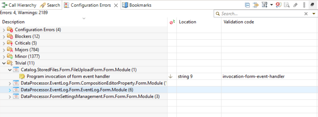
This panel is part of the default perspectives 1C:Enterprise and Debugging.
Opening the Configuration Errors Panel
Press Window > Show View > Other… > 1C:Enterprise > Configuration Errors in the main menu of the main window.
Information Structure
By default, upon first opening, information is grouped into several levels. At the first level, errors are grouped by project, which cannot be disabled. If only one project is open in the workspace, project grouping is not displayed since it is unnecessary.
Then, errors are further grouped by severity, configuration objects, and modules where errors of this category were found, with individual errors listed within these objects.
You can customize the grouping preferences for the list.
Legend
 The error was found in the project.
 The error was found in the module.
 The error was found in the configuration object.
 Error.
 Warning.
Columns
- Description provides the error description. If grouping is enabled, the same column in 1C:EDT also displays grouping fields such as error category, as well as the module, configuration object, and project where the error was found.
- Severity specifies the severity level of the error: Blocker, Critical, Major, Minor, Trivial.
- Object specifies the module or configuration object where the error was found.
- Location shows the module line number where the error is located.
- Project specifies the project where the error was found.
- Validation Code is the code of the validation that generated this marker. The code allows you to find all markers created by that validation and quickly adjust its settings, including disabling or suppressing the errors.
- Created shows the date and time when the automatic configuration validation detected this error.
Mouse Actions
- A single click with the Ctrl or Shift keys pressed selects multiple list rows for copying to the clipboard or exporting to a file.
- A double click on a group expands or collapses it.
- A double click on an error or warning opens the most appropriate editor for fixing the issue:
- Configuration Object Editor if the issue is in the configuration structure.
- Form Editor if the issue is related to event handler assignment.
- 1C:Enterprise Language Editor at the line with the error if the issue is in the 1C:Enterprise language code.
Command Bar
- (Collapse All) Collapses all hierarchy levels in the panel down to the first level.
- (Configure List) opens a dialog for configuring the configuration error list. Additional columns and groupings can be displayed, and their order can be changed. Sorting by the selected column and direction is available. A limit on the number of items displayed in each group can be set.
 (Set Filter) submenu contains options for filtering by error origin. Clicking Set Filter... opens the full error filter dialog, where, for example, you can filter only errors or only warnings.
 (Export to File) exports the list of errors to a .tsv file. This is a text file where each field is separated by a tab character. The structure, content, and order of rows in the file match the list representation configured by commands (Configure List) and (Set Filter).
Context Menu
 Copy copies the selected error and warning lines to the clipboard. If groups are selected, all error and warning lines within those groups are copied.
- Open Check opens the configuration validation parameters and positions on the selected validation.
- Suppress Error suppresses the selected error.
Handling Configuration Errors
Configure List Grouping
- Click (Configure List) in the command panel.
- Select the desired groupings, arrange them in the required order, and click OK.
Go to the Module Containing the Error
- Double-click the error.
1C:EDT will open the module containing the error or the configuration object editor at the tab where the error is located.
Open the Validation
- Click Open Check in the command panel.
Suppressing Configuration Validations
Sometimes it is necessary not to enable or disable an entire validation but rather suppress specific validation markers generated by that validation. For example, you might want to disable markers triggered by validation for a specific configuration object.
This need often arises when developing library solutions, where deviations from coding standards are made intentionally to ensure proper component structure in the final solution.
To address such cases, 1C:EDT provides a mechanism for suppressing validation results.
The application structure includes both the relationships between configuration objects and code written in the 1C:Enterprise language within modules. For this reason, the validation suppression mechanism consists of two independent components:
-
Object-Based Suppression of Validation Results allows suppressing both object-based and language-based validation markers.
-
Language-Based Suppression of Validation Results allows suppressing only language-based validation markers.
Object-Based Suppression of Validation Results
This mechanism allows you to configure validation suppression for:
-
The root configuration object.
-
A subsystem and its constituent objects.
-
A configuration object (e.g., a catalog Products).
-
A form.
Open the Validation Suppression Editor
- In the Navigator panel, select the object you want to configure.
- In the Properties panel, click Open Validation Suppression.
The editor displays the selected segment of the configuration object tree, where you can add or remove validation suppressions.
Editor Elements and Functions
 (Add) opens a dialog for selecting validations to suppress. This button is only active for tree elements where suppression can be added.
 (Remove) deletes the selected suppression. This button is active not only for suppressions but also for other tree elements. In such cases, it removes all suppressions assigned to the selected element and its child elements.
- Suppress All Validation Checks for the Object when selected, suppresses all validations related to the root object and its child elements.
If the Validation Suppression Editor is opened for a subsystem, it allows you to suppress validations for both the subsystem itself and all objects within it. Selecting the checkbox Suppress All Validation Checks for the Object only affects validations related to the subsystem itself. To suppress validations for objects within the subsystem, they must be explicitly added to the Composition branch.
- Search Field allows searching for the required element (attribute, tabular section, parameter, command, etc.) within the tree.
Language-Based Suppression of Validation Results
To configure suppression, add the comment // @skip-check to the semantic element of the module where you want to suppress validation.
Below are examples of how to apply suppression for different language elements.
For the Entire Module
Example:
// Module header, license, description

// **@skip-check NStr-contains-camelcase because in this module, we do not validate NStr for CamelCase**

// Procedure description with an empty line
Procedure MyProcedure()
   ...
   MessageText = NStr("en = 'Here in the text is CamelCase'.").
   ...
EndProcedure
To configure suppression, add the comment // @skip-check to the beginning of the module before the first semantic element.
<// Module comments 1 | empty line>
...
<// Module comments N | empty line>
// @skip-check *code-1*, *code-2*, *code-3* - *comment*
<// Module comments N+2 | empty line>

<First semantic element>
Here, code-1, code-2, code-3 are validation codes whose results you want to suppress, and comment is a custom comment for developers. Validation codes are listed with or without spaces, separated by commas, and the comment is separated by a space and a hyphen.
For a Method
Example:
// Module header, license, description

// Procedure description with an empty line
// **@skip-check NStr-contains-camelcase because in this method, we do not validate NStr for CamelCase**
Procedure MyProcedure()
   ...
   MessageText = NStr("en = 'Here in the text is CamelCase'.").
   ...
EndProcedure
To configure suppression, add the comment // @skip-check before the target method.
<Module comments>

// @skip-check *code-1*, *code-2*, *code-3* - *comment*
Procedure
   ...
EndProcedure
Here, code-1, code-2, code-3 are validation codes whose results you want to suppress, and comment is a custom comment for developers. Validation codes are listed with or without spaces, separated by commas, and the comment is separated by a space and a hyphen.
For a 1C:Enterprise Language Statement
Example:
// Example of disabling a single validation ACC:1036
// **@skip-check ACC:1036 - Do not check the line for spelling**
AddHolidayTsagaanSar(HolidayDays, YearNumber).

// Example of disabling two validations - ACC:1036 and ACC:1037
// **@skip-check ACC:1036, ACC:1037 - Do not check the line for spelling**
AddHolidayTsagaanSar(HolidayDays, YearNumber).

// Example of disabling a single validation ACC:1036, inline
AddHolidayTsagaanSar(HolidayDays, YearNumber). // **@skip-check ACC:1036 - Do not check the line for spelling **
// Example of disabling two validations - ACC:1036 and ACC:1037, inline
AddHolidayTsagaanSar(HolidayDays, YearNumber). // **@skip-check ACC:1036, ACC:1037 - Do not check the line for spelling**
To configure suppression, add the comment // @skip-check before the required statement or in the same line.
// List of codes separated by commas, with or without spaces, comment separated by space and hyphen

// Option - before the statement, single annotation (nearest)
// @skip-check *code-1*, *code-2*, *code-3* - *comment*
<statement>

// Option - inline
<statement> // @skip-check *code-1*, *code-2*, *code-3* - *comment*
Here, code-1, code-2, code-3 are validation codes whose results you want to suppress, and comment is a custom comment for developers. Validation codes are listed with or without spaces, separated by commas, and the comment is separated by a space and a hyphen.
For a Code Block
For example, an area covering multiple procedures:
// **@skip-check NStr-contains-camelcase - valid exception for an area covering multiple procedures**
#Region SpecialProceduresNStr

Procedure MyProcedure()
   ...
   MessageText = NStr("en = 'Here in the text is CamelCase'.").
   ...
EndProcedure

Procedure MyProcedure2()
   ...
   MessageText = NStr("en = 'Here in the text is CamelCase 2'.").
   ...
EndProcedure

#EndRegion
For example, an area inside a procedure:
Procedure MyProcedure()
   ...

// **@skip-check NStr-contains-camelcase - valid exception for an area covering lines of code inside a procedure**
#Region SpecialCodeAreaNStr

   ...
   MessageText = NStr("en = 'Here in the text is CamelCase'.").
   ...

#EndRegion
   ...
EndProcedure
To configure suppression, add the comment // @skip-check before the required region.
// Before the region, without a line break. Supports regions inside methods
// @skip-check *code-1*, *code-2*, *code-3* - *comment*
#Region SpecialProceduresNStr
   ...
#EndRegion
Here, code-1, code-2, code-3 are validation codes whose results you want to suppress, and comment is a custom comment for developers. Validation codes are listed with or without spaces, separated by commas, and the comment is separated by a space and a hyphen.
Documenting Comments
General Information
A documenting comment is a comment for a custom procedure or function written according to specific rules.
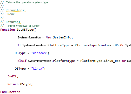
The comment lists the parameters, their types and purposes, and the type and purpose of the return value.
1C:EDT uses this information and displays it in the same way as similar information for system procedures and functions of the 1C:Enterprise platform.
- This information is displayed in the Syntax Assistant panel.
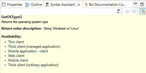
- This information appears in a tooltip when hovering over a method call.
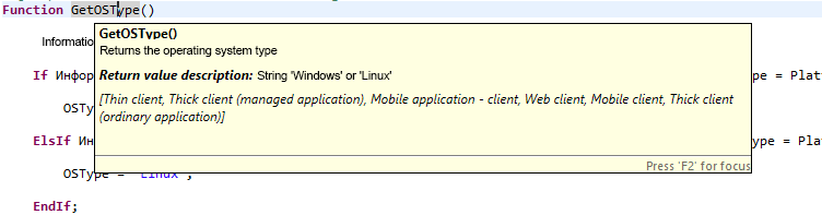
- This information is used by the context hint when entering procedure or function parameters.
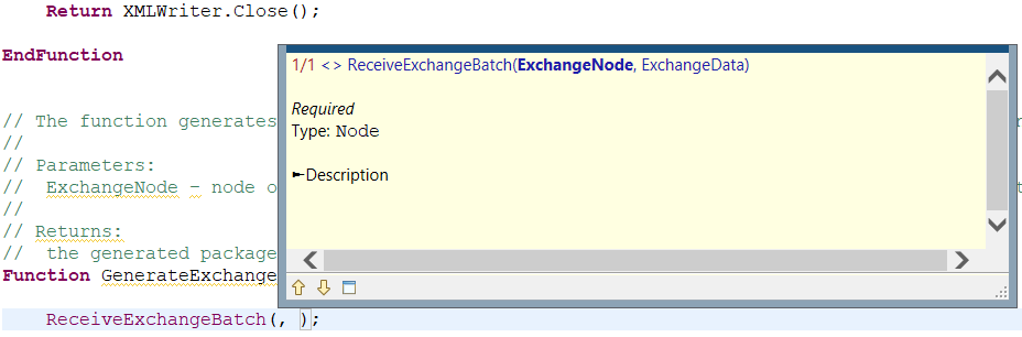
-
If a parameter or return value has the type Structure, ValueTable, or ValueTree, a documenting comment can describe the names and types of keys and columns. Then the context hint will display this data when accessing it through a dot from the parameter or from the return value.
-
The parameter's value type can be described as a reference to a function that returns this value. In this case, 1C:EDT allows for a quick jump to the declaration of that function.
-
The types specified in documenting comments can be used by 1C:EDT for validation in strict type enforcement mode.
Rules for Writing Documenting Comments
The rules for writing documenting comments are defined in the system of standards and guidelines for configuration development. Specifically, in the sections:
Bsl Documenting Comment Panel
The EDT package includes the 1C:Code Style V8 plugin. This plugin contains this panel. It is located in the 1C:Enterprise perspective.
It displays the structure of the documenting comment, allowing for proper formatting of complex comments. It enables the correction of mistakes made when writing comments.
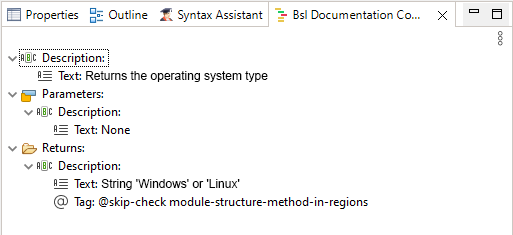
The description of the panel can be found in the 1C:Code Style V8 plugin documentation.
To open the panel, click Window > Show View > Other... > 1C:Development Standards V8 > Bsl Documenting Comment
Continue a Multiline Comment
Comments are often long and do not fit on a single line. To quickly continue a comment on the next line, press Shift+Enter.
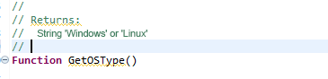
A new line will be automatically added, already containing the comment symbol at the beginning.
Generating Comments for a Method
To insert a documenting comment template, follow these steps:
-
Place the cursor on a blank line directly before the method declaration or on the declaration itself.
-
Click Source Generate Method Comments in the context menu.
This command can not only insert a new comment but also improve an existing one.
For example, if a new parameter has been added to the method declaration, this command will add it to the comment.
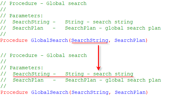
If the comment does not follow the rules, it will be supplemented and formatted according to the standard.
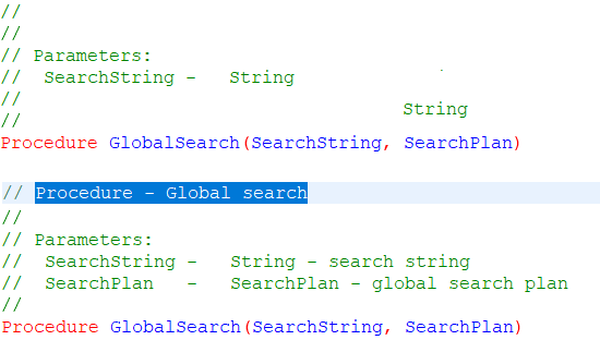
Type Checking Errors
Documenting comments alone will not cause 1C:EDT to detect type mismatches. In addition to describing parameter types and return values in documenting comments, strict typing must be enabled for the entire application, specific objects, or certain modules.
The 1C:EDT package includes the 1C:Code Style V8 plugin. This plugin allows enabling strict typing.
Until strict typing is enabled, 1C:EDT does not check for compliance between declared and used types. Once strict typing is enabled, 1C:EDT will report any such errors. For example, if you specify that a parameter has the type String and pass a value of type Number.
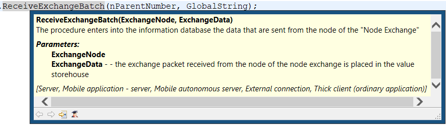
Strict typing is enabled by adding the annotation //@strict-types at the beginning of modules.
Enabling Strict Typing
- In the Navigator panel, select the project or configuration if you want to enable it for the entire application, a configuration object if you want to enable it only for its modules, or a module if you want to enable it only for that module.
- Click Enable Strict Typing (@strict-types) in Modules in the context menu.
Performance Meter
Performance Meter allows you to evaluate the execution speed of an entire configuration or a specific part running within any type of debug target. It measures how often specific code segments are used and how quickly they execute. It indicates which code was executed on the server and which was processed on the client. It also identifies the lines of code that triggered a server call.
If multiple programming approaches exist for a particular task, you can implement all of them and then select the fastest one.
However, it is important to ensure that comparisons are made under the same conditions. For example, if the computer’s processor was handling another task while one of the compared methods was running, it could affect the accuracy of the comparison. Other, less obvious factors may also cause differences in measurement conditions. Therefore, when comparing two approaches with similar performance, it is recommended to perform multiple measurements for each approach to assess and average out random deviations.
More details on performance measurement can be found in 1C:Enterprise documentation.
Measure Performance
Performance measurement is only available when the application is running in debug mode.
To perform a measurement, you need to start it at a certain moment and stop it at another moment. Both actions are run using the same command in the Main Window Command Bar—![]() (Performance Meter).
(Performance Meter).
When the measurement is completed, 1C:EDT automatically opens the Performance Meter panel displaying the measurement results.
Measuring Performance at Application Startup
To measure performance, including the section executed during application startup, follow these steps:
-
Click
(Performance Meter) in the Main Window Command Bar to enable measurement. -
Launch the application in debug mode.
-
After the required actions have been completed, click
(Performance Meter) to stop the measurement.
1C:EDT will open the Performance Meter panel.
The time elapsed between the start of measurement and the beginning of the application’s execution will not be included in the measurement results.
Measuring an Arbitrary Section of Interactive Actions
To measure the performance of one or more interactive operations, follow these steps:
-
Launch the application in debug mode.
-
Prepare the application to execute the desired section.
-
Switch to 1C:EDT and click
(Performance Meter) in the Main Window Command Bar to start the measurement. -
Switch to the application and perform the required sequence of actions.
-
Switch back to 1C:EDT and click
(Performance Meter) to stop the measurement.
1C:EDT will open the Performance Meter panel.
Measuring an Arbitrary Section of Program Code
To measure the performance of an arbitrary section of program code, follow these steps:
-
Set breakpoints at the beginning and end of the section you want to measure.
-
Launch the application in debug mode.
-
Perform the sequence of actions that leads to a breakpoint at the start of the section.
-
Once execution is paused, click
(Performance Meter) in the Main Window Command Bar to start the measurement. -
Resume program execution.
-
Once execution stops at the end of the section, click
(Performance Meter) to stop the measurement.
1C:EDT will open the Performance Meter panel.
Measuring Performance at Application Shutdown
To measure performance, including the section executed during application shutdown, follow these steps:
-
Launch the application in debug mode.
-
Prepare the application to execute the desired section.
-
Switch to 1C:EDT and click
(Performance Meter) in the Main Window Command Bar to start the measurement. -
Perform the required sequence of actions and close the application. The Performance Meter panel will open.
View Performance Measurement Results
Measurement results are automatically saved in the workspace. You can view them immediately after measurement or at any convenient time.
In the Performance Meter panel
If the Performance Meter panel is open, it typically displays the results of the most recent measurement.
Double-clicking a measurement entry will open the module containing that entry. The 1C:Enterprise Language Editor will highlight the executed instruction.
In the Module
Measurement results can also be viewed within the module. To do this, in the vertical ruler, open the context menu and select Performance Meter Show Measurement Results.
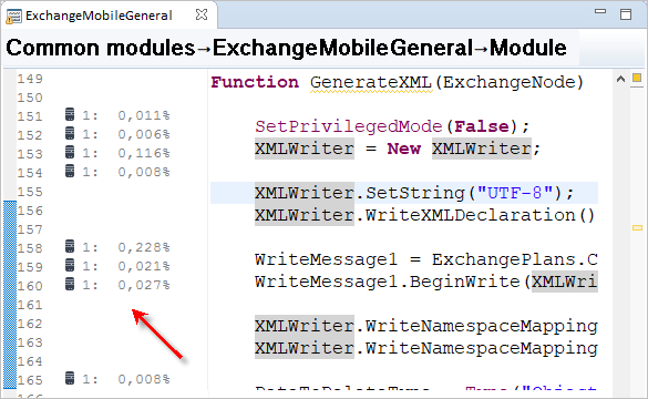
Performance Meter Panel
The Performance Meter panel displays the results of measurements taken during debugging.
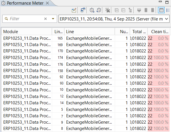
This panel opens automatically after a measurement is completed (when the ![]() (Performance Meter) button in the Main Window Command Bar is released). Measurement results are automatically saved in the workspace and can later be used for viewing, comparison, or export to another project. Each measurement has a default name, which you can change.
(Performance Meter) button in the Main Window Command Bar is released). Measurement results are automatically saved in the workspace and can later be used for viewing, comparison, or export to another project. Each measurement has a default name, which you can change.
Open the Performance Meter panel
Click Window > Show View > Other… > 1C:Enterprise > Performance Meter in the main menu of the main window.
Information Structure
By default, measurement results are displayed as a list of executed operators, where, in addition to the operator (column Line), the module (column Module) and the line number (column Line Number) where the operator is located are specified.
Additionally, measurement results can be displayed in a more generalized form—as a list of methods that were executed. This list can be further grouped by modules.
Legend
 Code executed on the client.
 During execution, the code makes a call to the server.
 Code executed on the server.
 In column Net Time (s), the background color and width indicate the proportion (percentage) of the total measurement time that was spent executing a particular line.
 The default measurement name consists of the project name (DemoUP_14), the measurement date (15:44:11, Fri, Aug 30, 2019), and the debug targets (Thin Client). A custom prefix can be added to the default name. From the drop-down list, one of the available measurements in the workspace can be selected to display its results in the panel.
Columns
- Module The module to which the line of code belongs. This column is displayed if the measurement results are presented as a table of operators.
- Line Number The line number in the module. This column is displayed if the measurement results are presented as a table of operators.
- Line The line of code that was executed. This column is displayed if the measurement results are presented as a table of operators.
- Method The method that was executed. This column is displayed if the measurement results are presented as a list of methods.
- Call Count Indicates how many times this line of code was executed during the profiling session.
- Total Time (s) Total execution time of a line of code. It consists of the method call time (not displayed in the table) and the net execution time of the operator, which is shown in column Net Time (s).
- Net Time (s) Net execution time of an operator (excluding procedure or function call time). This column also shows the percentage share of this operator's execution time relative to the total profiling time.
- Client This column uses an icon to indicate lines executed on the client.
- Standalone Server This column marks lines executed on the standalone server of a mobile client with offline mode.
- Server This column uses an icon to indicate lines executed on the server.
- Server Processing This column uses an icon to indicate lines that triggered a server call.
Mouse Actions
- Double-clicking a line opens the module in the 1C:Enterprise Language Editor and positions the cursor on the executed operator or method (if results are displayed as a list of methods).
Command Bar
 (Rename Result) allows you to add a custom string at the beginning of the standard measurement name.
 (Compare With...) allows you to compare the current measurement with another measurement.
 (Import Measurement Results) imports measurement results into 1C:EDT.
 (Export Performance Results) exports measurement results from 1C:EDT.
 (Clear Results) clears the Performance Meter panel and measurement history.
- (Expand All) Expands all hierarchy levels in the panel.
- (Collapse All) Collapses all hierarchy levels in the panel down to the first level.
 (Group Methods by Modules) Groups methods by modules if the measurement results are presented in the method list format.
- (Client Results) if selected, displays statements executed on the client and possibly on the server (if (Server Results) is selected). If unchecked, only statements executed on the server are displayed.
- (Standalone Server Results) if selected, displays statements executed on the standalone server and possibly on the client (if (Client Results) is selected). If unchecked, only statements executed on the client are displayed.
- (Server Results) if selected, displays statements executed on the server and possibly on the client (if (Client Results) is selected). If unchecked, only statements executed on the client are displayed.
 (Tabular View) measurement results are presented as a table of executed statements with columns Module, Line Number, and Line.
 (Method List) measurement results are displayed as a list of executed methods. You can group this list by modules.
Compare Two Performance Measurements
Measurement results are automatically saved in the workspace. You can compare the current measurement with any previously recorded measurement.
Compare the Current Measurement with Another Measurement
- Click (Compare With...) in the command panel.
- Select the desired measurement from the top table.
- Click Done.
The bottom table displays the contents of the selected measurement for reference.
1C:EDT will open the performance comparison panel.
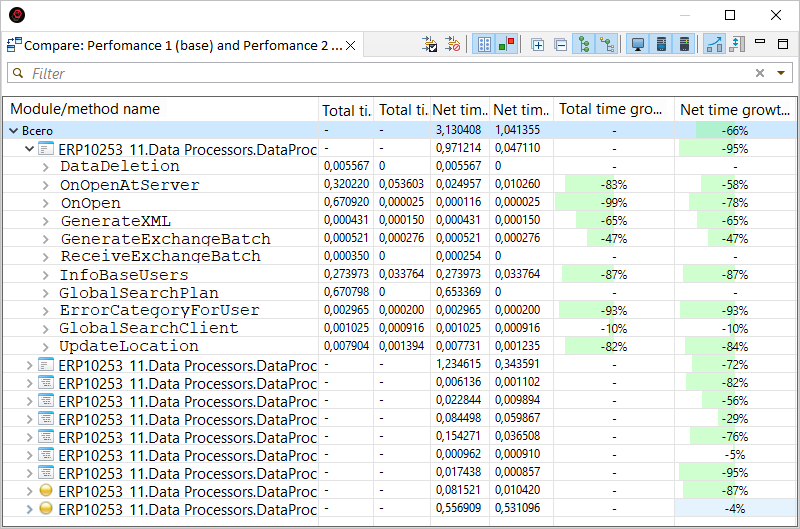
Structure of Information in the Panel
By default, the table displays operators from the compared measurements, grouped by methods and by modules. The table columns show the total execution time of an operator in both the base and comparison measurements, as well as the net execution time of the operator in both cases.
Additionally, by default, the panel displays changes in these values, expressed as growth rate. Growth rate is calculated using the formula:(compared - baseline) / baseline. You can enable a different display mode in the form of share differences.
Columns
- Total Time (Base) refers to the base measurement. It is the total execution time of a line of code. It consists of the method call time (not displayed in the table) and the net execution time of the operator, which is shown in column Net Time (s).
- Total Time (Compared) refers to the compared measurement. It is the total execution time of a line of code. It consists of the method call time (not displayed in the table) and the net execution time of the operator, which is shown in column Net Time (s).
- Net Time (Base) refers to the base measurement. It is the net execution time of an operator (excluding procedure or function call time). This column also shows the percentage share of this operator's execution time relative to the total profiling time.
- Net Time (Compared) refers to the compared measurement. It is the net execution time of an operator (excluding procedure or function call time). This column also shows the percentage share of this operator's execution time relative to the total profiling time.
- Total Time Growth Rate shows the change in total time expressed as a growth rate. Growth rate is calculated using the formula: (compared - baseline) / baseline. It is displayed when the button
 (Show Growth Rate) is pressed.
 - Net Time Growth Rate shows the change in net time expressed as a growth rate. Growth rate is calculated using the formula: (compared - baseline) / baseline. It is displayed when the button (Show Growth Rate) is pressed.
- Total Time Share Difference shows the change in total time expressed as a share difference. Share difference is calculated using the formula: (compared line time / compared profiling time) - (baseline line time / baseline profiling time). It is displayed when the button
 (Show Time Percentage Difference) is pressed.
 - Net Time Share Difference shows the change in net time expressed as a share difference. Share difference is calculated using the formula: (compared line time / compared profiling time) - (baseline line time / baseline profiling time). It is displayed when the button (Show Time Percentage Difference) is pressed.
Mouse Actions
- A single click on the column header sorts the table rows by that column. If they are already sorted by that column, the sorting direction is reversed.
- A double-click on a row containing an operator opens the module in the 1C:Enterprise Language Editor and positions the cursor at that operator.
Command Bar
 (Set Difference Threshold) sets the difference threshold in seconds. Difference Threshold is the delta value (the difference between two measured values) from which the comparison mechanism will display a change in value. Setting a difference threshold allows you to filter out minor and insignificant changes in the comparison results.
 (Reset Difference Threshold) resets the difference threshold and displays all comparison results.
 (Exact Values) if pressed, the panel displays columns Total Time (s) and Net Time (s) for the base and compared measurements.
 (Change) if pressed, the panel displays columns Total Time Growth Rate and Net Time Growth Rate or columns Total Time Share Difference and Net Time Share Difference.
- (Expand All) Expands all hierarchy levels in the panel.
- (Collapse All) Collapses all hierarchy levels in the panel down to the first level.
- (Group Methods/Lines by Modules) When enabled, the panel lines are grouped by modules.
 (Group Lines by Methods) When enabled, the panel lines are grouped by methods.
- (Client Results) if selected, displays statements executed on the client and possibly on the server (if (Server Results) is selected). If unchecked, only statements executed on the server are displayed.
- (Server Results) if selected, displays statements executed on the server and possibly on the client (if (Client Results) is selected). If unchecked, only statements executed on the client are displayed.
- (Show Growth Rate) changes are displayed as a growth rate in columns Total Time Growth Rate and Net Time Growth Rate. Growth rate is calculated using the formula: (compared - baseline) / baseline.
- (Show Time Percentage Difference) changes are displayed as a percentage difference in columns Total Time Share Difference and Net Time Share Difference. Share difference is calculated using the formula: (compared line time / compared profiling time) - (baseline line time / baseline profiling time).
Exporting and Importing Performance Measurement Results
Performance measurement results can be saved to files or loaded from files.
Exporting Measurements
- In the Performance Meter panel, click (Export Performance Results) in the command bar.
- In the Full Path field, select the directory where the measurement results will be saved.
- Uncheck the measurements that do not need to be exported.
- Click Done.
The same actions can be run in the Navigator panel. To do this, click Export... > 1C:Enterprise > Performance Meter.
Importing Measurements
- In the Performance Meter panel, click (Import Measurement Results) in the command bar.
- In the Full Path field, select the directory containing the measurement results.
- Uncheck the measurements that do not need to be imported.
- Click Done.
If the selected directory contains already imported measurements, they will be marked with a third checkbox state. Such measurements cannot be imported, but their checkboxes can be cleared.
The same actions can be run in the Navigator panel. To do this, click Import... > 1C:Enterprise > Performance Meter.
Chapter 9. Launching 1C:Enterprise Client Applications
-
Different Platform Versions for Running a Single Configuration
-
Selecting the Platform Version for Updating, Running, and Using Designer
Thin Client
Thin Client is a 1C:Enterprise client application that runs on the user's computer and provides interactive interaction with the infobase. This can be either a file-based mode or a client-server mode with a 1C:Enterprise server cluster.
The thin client application is 1cv8c.exe.
It is called a "thin" client because it can only execute a limited subset of the 1C:Enterprise language functionality. Specifically, all applied data types are unavailable in the thin client. Instead, it operates with a restricted set of 1C:Enterprise language types designed only for displaying and modifying data in memory. All database operations, object data handling, and query execution are run on the server side. The thin client only receives prepared data for display.

The thin client can connect to infobases over the Internet. It must be preinstalled on the user's computer but has a significantly smaller installation package than the thick client.
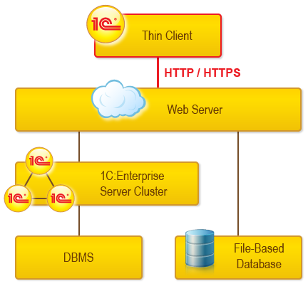
Web Client
Web Client is a 1C:Enterprise client application that runs on the user's computer and provides interactive interaction with the infobase. This can be either a file-based mode or a client-server mode with a 1C:Enterprise server cluster. The web client connects through a web server (Apache or Internet Information Services) where the infobase must be published in advance.
The web client does not require prior installation on the computer. Unlike the Thick Client and Thin Client, it does not run within the computer's operating system but instead operates in a web browser environment (Internet Explorer, Mozilla Firefox, Google Chrome, or Safari). Thus, a user only needs to launch their browser, enter the web server address where the infobase is published, and the web client will "arrive" on the computer and start executing automatically.
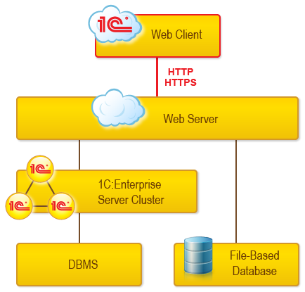
Thick Client
Thick Client is a 1C:Enterprise client application that runs on the user's computer and provides interactive interaction with the infobase. This can be either a file-based mode or a client-server mode with a 1C:Enterprise server cluster.
The thick client application is 1cv8.exe.
The thick client allows full execution of 1C:Enterprise applied code. It includes the development environment called Designer, which is used to modify applications.
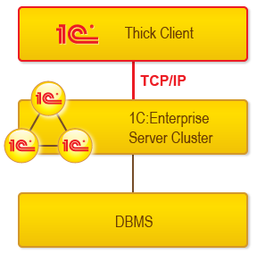
The thick client does not support connecting to infobases over the Internet, requires prior installation on the user's computer, and has a relatively large installation package size.
External Connection
External Connection is a connection between an external process and the infobase, allowing management of the 1C:Enterprise client application from other applications.
An external connection is established by connecting to the infobase using COM technology.
For example, in MS Visual Basic, the connection can be established as follows:
Dim cntr As Object      'COM Connection Manager
Dim extconn As Object   'External Connection

Set cntr = CreateObject("V83.COMConnector")
Set extconn = cntr.Connect("File=""c:\InfoBases\Trade"". Usr=""Director"".")
In the 1C:Enterprise language, the connection can be established as follows:
// Create COM Connection Manager
ManagerCOMConnection = New COMObject("V83.COMConnector").

// Establish connection to infobase
ExternalConnection = ManagerCOMConnection.Connect("Srvr=""TestSrv"".Ref=""TestBase""").
When an external connection is created, a relatively small in-process COM server without a user interface is launched. Thus, functionality related to the user interface is unavailable.
When launching an external connection, the External Connection Module is executed. It can handle the following events at the start and end of operation: OnStart and OnExit.
Operations Performed When Launching a 1C:Enterprise Client Application
During application launch, 1C:EDT performs the following operations:
-
It connects to the infobase to ensure that the configuration in the project and the configuration in the infobase are identical. To connect to the infobase, 1C:EDT starts the platform version specified in the infobase access settings.
-
If the configurations differ, 1C:EDT updates the configuration in the infobase:
-
It loads the configuration from the project (either entirely or just the changes) into the infobase.
-
It updates the main configuration of the database. If infobase restructuring is required, 1C:EDT will display an informational message requesting confirmation.
-
-
It launches the client application. To launch the client application, 1C:EDT uses the platform version specified in the launch configuration, which is set in the Field "Application: Version".
Launch Configurations
Launch configurations are a set of parameters that 1C:EDT uses to run applied solutions. The main parameters required to run are:
-
The project that contains the application configuration
-
The infobase that will be used for this configuration
-
The 1C:Enterprise client application that will be launched
When you launch a project for the first time, 1C:EDT helps you create a launch configuration and saves it. From then on, 1C:EDT automatically selects this configuration for launching the project without additional prompts (learn more).
Available launch configurations can be edited or deleted. You can create new launch configurations, including copying and modifying existing ones (learn more).
Run and debug configurations can be shared with other developers using the export and import operations for launch configurations (learn more).
Different Platform Versions for Running a Single Configuration
The same infobase associated with a project can be launched using different platform versions. For example, one version is the current active one, 8.3.22.x, while another version is a future one, 8.3.23.x, which you plan to migrate your configuration to.
To achieve this, you can create different launch and debug configurations. These allow you to select not only platform versions that match the project's version but also later ones.
It may also be useful to have multiple launch configurations within the same major platform version. For example, you may need to verify bug fixes introduced in a previous release. Launch and debug configurations allow you to specify precise four-digit platform versions, not just version templates.
Selecting the Platform Version for Updating, Running, and Using Designer
1C:EDT can be used with different versions of the 1C:Enterprise platform (learn more). For a project, only a platform version template can be specified. Infobases may be designed to interact with a specific platform version or a range of versions. How does 1C:EDT determine which platform version to use in this case?
The main platform version that 1C:EDT uses for the infobase is the one specified in the infobase access settings.
You can specify an exact platform version there, and 1C:EDT will use it.
Alternatively, a version mask may be specified, which is the most common case. If a mask is used, 1C:EDT selects the latest platform version that matches the mask. If you do not want the latest version that matches the mask to be used, you can specify a particular platform version to be selected when applying this mask (learn more).
For various reasons, a specific platform version may be required for the infobase: The simplest case is a server-based infobase. Assume you have the following platform versions installed:
-
8.3.10.2753,
-
8.3.10.2505,
-
8.3.10.2466.
Server components are only available in the "middle" version, 2505. How does 1C:EDT handle a server infobase in this case?
Importing a Configuration from the Infobase
When importing a configuration, only a platform version mask can be specified: <8.3.10> (learn more). 1C:EDT will use the latest version that matches this mask, 8.3.10.2753. However, this version does not include server components, so the import will fail.
To complete the import successfully, you must first assign a specific version (8.3.10.2505) to the <8.3.10> mask (learn more), perform the import, and then restore the mask to its original state.
Exporting a Configuration from the Project to the Infobase and Updating the Configuration
For exporting a configuration to the infobase and updating the configuration in the infobase, 1C:EDT will use the platform version specified in the infobase access settings. You can specify an exact version, such as 8.3.10.2505, which is essential for 1C:EDT to function correctly in all other usage scenarios.
In this example, after importing the configuration, 1C:EDT will automatically set the mask chosen for the project during import: <8.3.10>. This means that for exporting and updating the configuration, 1C:EDT will use the latest version, 8.3.10.2753.
Launching the Application by Default
If a project is linked to an infobase, 1C:EDT only needs to know which client application you want to launch. Therefore, the project's context menu Run As lists the client applications. When you select one of them, 1C:EDT launches the application without requesting additional information.
For launching, 1C:EDT uses the platform version specified in the infobase access settings, which in this case is 8.3.10.2505.
Creating a Launch Configuration and Running the Application
Another option is to create a launch configuration and use it for launching (learn more). In the launch configuration, you can select the exact platform version that will be launched, such as 8.3.10.2505. However, this does not guarantee a successful launch.
Before launching, 1C:EDT must update the configuration in the target infobase (learn more). At a minimum, it must ensure that the configuration in the project matches the one in the infobase. For this process, 1C:EDT uses the platform version specified in the infobase access settings.
If the version specified in the access settings is incorrect, the launch will fail.
The platform version specified in the launch configuration is only used by 1C:EDT to start the client application. This occurs after the configuration update in the infobase is completed. This feature is useful for testing how an application operates when launched with a later platform version.
Launching Designer
Without leaving 1C:EDT, you can launch 1C:Enterprise Designer for any infobase.
If the infobase is linked to a project, then when starting up, 1C:EDT launches Designer in agent mode to interact with it. In this case, 1C:EDT uses the platform version specified in the infobase access settings. To launch Designer "for you," 1C:EDT terminates the process running in agent mode and starts Designer with the same version.
Troubleshooting: If the infobase access settings specify an incorrect platform version, Designer will not be started in agent mode when 1C:EDT launches.
If the infobase is not linked to any project, then to start Designer, 1C:EDT will use the platform version selected according to the version mask specified in the Platform Version property of that infobase (see the Properties panel).
To modify this mask, click Open in the context menu of the infobase (learn more).
Creating a New Infobase
From within 1C:EDT, you can create a new infobase. To do this, 1C:EDT will use the platform version you select in the wizard (step 7).
1C:EDT Applications
A 1C:EDT application is a unit for loading, updating, and deploying a developed configuration. An application defines the link between a project and the 1C:Enterprise infobase on which the project is launched and debugged.
The Applications panel displays all applications associated with the current project (the project selected in the Navigator panel).
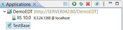
Opening the Applications Panel
Click Window > Show View > Other… > 1C:Enterprise > Applications.
The panel is populated automatically, for example, when importing an infobase into a new project. Applications can also be added manually.
Legend
The default application is highlighted in bold. This application:
-
Is launched when the project is run or debugged from the Navigator panel (Ctrl+F11 and F11).
-
Is launched when using a launch configuration where the default application is specified.
-
Is used when manually creating a new launch configuration.
Managing Applications
Find Applications Linked to a Project
1C:EDT will display all applications linked to this project in the Applications panel.
Relocate Application
An application linked to a project may or may not use the standalone server to interact with the infobase. You can change the application's deployment, meaning:
-
If the application does not use a standalone server, you can convert it into an application on a standalone server.
-
An application on a standalone server can be converted into an application that operates with the infobase without using a standalone server.
To change the deployment of an existing application, follow these steps:
-
Select the required project in the Navigator panel.
-
In the Applications panel, click Relocate Application in the application’s context menu.
-
In the Server Version field, select the platform version whose standalone server will be used for the application.
-
Click Finish.
Note: If the list for selecting the server version is empty, it means that the 1C:Enterprise Server component is not installed on your computer. The installed server version must match the project version used by this application.
Edit Application Properties
Double-click the application.
Field Descriptions
- Automatic Configuration Update for Infobases: the method used to update the main configuration in automatically updated infobases (learn more about automatically updated infobases).
Update During Editing
In this mode, configuration changes are constantly and automatically transferred to the infobase directly during editing. Each time you press Save in the 1C:Enterprise Language Editor, for example. Or immediately after adding a new attribute to a configuration object.
When placing these changes into the infobase, the incremental configuration upload from XML files mechanism is used. Thus, only changes made to the configuration since its last export from 1C:EDT are loaded into the infobase. This process works as follows:
- You modify the configuration in 1C:EDT. The modified objects are marked within 1C:EDT as needing to be loaded.
- 1C:EDT exports the modified objects from the 1C:EDT model to a temporary directory as configuration
.xmlfiles. - 1C:EDT calls the batch mode of Designer and performs an incremental configuration upload from these files.
- 1C:EDT deletes the temporary directory.
- If the upload is successful, 1C:EDT removes the objects from the list of those needing to be loaded. If unsuccessful, they remain on the list.
As a result, by the time you run the configuration, the infobase state will be the same as if you were editing it directly in 1C:Enterprise Designer. The infobase will contain the modified main configuration, fully matching the configuration in 1C:EDT. To launch it, the platform only needs to update the database configuration, carry out any necessary restructuring, and start the client application.
You could say that updating during editing ensures the highest level of readiness for the infobase to run.
Update Before Launch
In this mode, nothing is transferred to the infobase during editing. This is the main reason to choose this mode.
Otherwise, like updating during editing, it uses incremental configuration upload from XML files to transfer changes to the infobase. However, it does so only once, just before launch. Or when you manually click Update Database Configuration in the Main Window Command Bar.
Since only configuration changes are transferred, it does not take much time. However, depending on the length of time since the last launch, the accumulated modifications may still cause a noticeable delay.
- Access Settings - Edit allows modifying the settings required for automatic infobase updates.
- Debugging - Port is the port where the debug server will be launched.
- Publications is the list of infobase publications on different servers.
- (Publish Infobase...) publishes the infobase on the web server.
- (Publish Mobile Application...) publishes the mobile application on the web server.
 (Edit) opens the Publication Editor.
 (Delete) removes web server information from the list.
Add Another Infobase to the Project
To debug with different data, you can add one or more additional infobases to the project.
- Open the Applications panel.
- Select the required project in the Navigator panel.
- 1C:EDT will display all applications linked to this project in the Applications panel.
- Click
 (New Application).
 - Select an infobase with different data or create a new infobase.
- Click Finish.
- Set one of the applications as the default application.
Set as Default Application
Click Set as Default in the application's context menu.
1C:EDT will use the selected application as the default.
Command Bar
- (Collapse All) Collapses all hierarchy levels in the panel down to the first level.
 (Run) Launches the selected application.
- (Debug) Launches the selected application in debug mode.
 (Delete) Deletes the selected application from the list. Additionally, you can remove the associated infobase from the list and delete its files from the disk.
- (New Application) Adds a new application to the list.
Context menu
- Run Launches the selected application.
- Debug Launches the selected application in debug mode.
- Set as Default means the selected application will be used by default.
- Delete Deletes the selected application from the list. Additionally, you can remove the associated infobase from the list and delete its files from the disk.
- Open opens the Application Editor.
- Run Designer launches the 1C:Enterprise platform and opens the infobase in Designer mode (about selecting the platform version).
- Update Configuration... exports the configuration from the project to the infobase (about selecting the platform version) and then updates the database configuration.
- Import Configuration... imports the configuration and extensions, if any, from the infobase into a new configuration project (about selecting the platform version).
- Import Extensions... imports extensions from the infobase into new extension projects.
- Save Configuration to File... saves the configuration or extension contained in the infobase to a `.cf` file.
- Dump Infobase... exports the infobase to a `.dt` file.
- Load Infobase... loads an infobase from a `.dt` file.
- Administration menu contains commands that launch the web client and open several standard features for technical specialists (see 1C:Enterprise documentation for details). Commands are only active for those infobases that are published on the web server.
- Users... opens the standard Users feature. Allows you to modify the user list (see 1C:Enterprise documentation for details).
- Active Users... opens the standard Active Users feature. Displays a list of users currently using the 1C:Enterprise system (see 1C:Enterprise documentation for details).
- Event Log... opens the standard Event Log feature. Allows you to view the event log (see 1C:Enterprise documentation for details).
- Authentication Lock... opens the standard Authentication Lock feature. Allows you to view the list of users whose authentication is blocked, unlock those users, and configure the mechanism that automatically blocks users after password brute-force attempts (see 1C:Enterprise documentation for details).
- Event Log Options... opens the standard Event Log Options feature. Provides access to event log settings for the infobase (see 1C:Enterprise documentation for details).
- Infobase Regional Settings... opens the standard Infobase Regional Settings feature. Allows you to edit the regional settings of the infobase (see 1C:Enterprise documentation for details).
- Set License Client Settings... opens the standard Set License Client Settings feature. Allows you to specify access parameters to the 1C:ITS portal to validate software licensing (see 1C:Enterprise documentation for details).
- Infobase Settings... opens the standard Infobase Settings feature. Provides access to the infobase parameter configuration dialog (see 1C:Enterprise documentation for details).
- Obtain License... opens the standard Obtain License feature. This dialog allows you to activate a software license without using Designer (see 1C:Enterprise documentation for details).
- Relocate Application converts the application to use a standalone server or reverts it.
Launch Scenarios
Successful Launch Conditions
Certain conditions must be met to successfully launch the applications being developed. 1C:EDT itself cannot launch or debug an application. Additional software is required.
First, the 1C:Enterprise platform must be installed on the computer, as it is necessary for all operations run during the launch process. Details on installing the platform can be found in the 1C:Enterprise documentation.
Additionally, a 1C:Enterprise infobase is required. There is no need to create the infobase in advance. If there are no infobases on the computer, 1C:EDT will assist in creating one during the launch process.
Below are specific considerations to keep in mind when launching different client applications with various infobases.
Launching Any Client Applications
- The access settings for the infobase being launched must be configured correctly. Otherwise, connection errors or change validation failures may occur.
- If users exist in the infobase, the project must contain a role with administrative privileges matching the internal identifier of the one in the infobase configuration. Otherwise, this error may occur.
- The platform version in the project must not be lower than the platform version in the infobase configuration. Otherwise, this error may occur.
Launching the Web Client
- A supported web server for the 1C:Enterprise platform must be installed in advance. The web server must be installed on the same computer as 1C:EDT. Instructions for installing the web server can be found in the 1C:Enterprise documentation.
- The bitness of the 1C:Enterprise platform (32-bit or 64-bit) must match the bitness of the web server. Otherwise, publishing the infobase on the web server will either be impossible or come with difficulties.
- If you do not have administrator rights in the operating system, it is highly recommended to run 1C:EDT as an administrator in advance (learn more) to avoid encountering such errors.
Launching on a Server Infobase
- A 1C:Enterprise server cluster must be installed in advance. The cluster can be installed on the same computer as 1C:EDT or on any other computer accessible via the HTTP protocol. Instructions for installing the server cluster can be found in the 1C:Enterprise documentation.
- A supported DBMS for the 1C:Enterprise platform must also be installed in advance. Instructions for installing the database server can be found in the 1C:Enterprise documentation.
- The platform version in the project must fully match the version of the 1C:Enterprise server cluster.
Quick Launch
To launch an application developed in the project:
-
Select the project in the Navigator panel.
-
Click
(Run As...) in the Main Window Command Bar.
1C:EDT launches applications using launch configurations.
If the project is being launched for the first time, 1C:EDT will ask which 1C:Enterprise client application should be launched.
Then, 1C:EDT will prompt you to create an application by linking the project to an infobase where the configuration in the project will be launched. You can either select an existing infobase or create a new one.
After this, the launch configuration will be saved, and the application will be launched.
From then on, when you click ![]() (Run As...), 1C:EDT will automatically select this launch configuration for your project without additional prompts. If your project uses multiple applications, it is more convenient to launch them from the Applications panel by selecting the desired application.
(Run As...), 1C:EDT will automatically select this launch configuration for your project without additional prompts. If your project uses multiple applications, it is more convenient to launch them from the Applications panel by selecting the desired application.
Another way to quickly launch an application is to directly choose the client application you want to run. To do this, use the Run As submenu, which is available in two locations:
-
In the Main Window Command Bar, click
(Run As...) Run As. -
In the Navigator panel, click Run As in the project context menu.
If the application launch fails, check the list of known issues. It describes the causes and solutions for problems you may encounter.
More information on selecting the platform version for launch is available here.
Relaunching with Another Client Application
The launch configurations for the thin client, thick client, and web client are very similar, so 1C:EDT simplifies the process of launching a different client application when a launch configuration already exists for one of these client applications.
To do this, use the submenu Run As, which is available in two locations:
-
In the Main Window Command Bar, click
(Run As...) Run As. -
In the Navigator panel, click Run As in the project context menu.
Select the desired client application from the submenu.
1C:EDT will take the existing launch configuration for the project and use it with the selected client application. A new launch configuration will not be created.
This scenario does not apply to launching the mobile client. Its launch configuration is not used for other clients, and when selecting the mobile client, 1C:EDT does not use existing launch configurations but creates a new one.
More information on selecting the platform version for launch is available here.
Using Multiple Launch Configurations
If multiple launch configurations are associated with a single project, clicking ![]() (Run As...) or
(Run As...) or ![]() (Debug As...) in the Main Window Command Bar will cause 1C:EDT to select the most recently used configuration.
(Debug As...) in the Main Window Command Bar will cause 1C:EDT to select the most recently used configuration.
If you want to launch the project with a different launch configuration, you can select it from the launch history. The launch history is located in the middle section of the ![]() (Run As...) and
(Run As...) and ![]() (Debug As...) command submenus.
(Debug As...) command submenus.
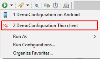
If you frequently use multiple launch configurations, you can add them to favorites and arrange them in the order that is most convenient for you. Favorites are located at the top of this same menu.
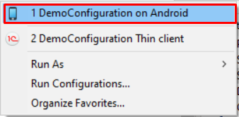
Favorites exist separately for configurations used for launching and those used for debugging. To add a launch configuration to favorites, click in the Main Window Command Bar:
-
(Run As...) Manage Favorites... for configurations used for launching, or
-
(Debug As...) Manage Favorites... for configurations used for debugging.
Exporting and Importing Launch Configurations
You can share launch configurations with colleagues. For example, this allows you to transfer complex connection parameters required for debugging a developed configuration.
You can export the necessary launch configurations, send them to a colleague, and they can import them into their workspace.
To do this, use the export and import commands available in the context menu of the Navigator panel:
-
Export... > Run/Debug > Launch Configurations.
-
Import... > Run/Debug > Launch Configurations.
Using the Standalone 1C:Enterprise Server
Standalone 1C:Enterprise Server
The standalone server is a server application for 1C:Enterprise, similar to a server cluster. Like a server cluster, a standalone server serves as an intermediary between a client application and a database. It also handles data processing operations, transferring only the necessary data selection to the client application.
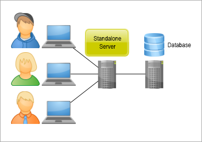
The main differences between a standalone server and a server cluster are as follows:
-
A running standalone server interacts with only one infobase.
-
The standalone server includes a built-in web server, which allows the configuration to be published and accessed via the web client.
When using a standalone server in 1C:EDT, you gain the following advantages over accessing a file-based infobase directly:
-
Full configuration import and export runs faster.
-
The configuration is published on the web server immediately, enabling you to launch and debug the web client.
-
Infobase administration commands are available (in the infobase context menu and in the application context menu).
-
For testing and debugging, it is better to use a full-fledged server architecture provided by the standalone server.
-
The standalone server also runs on macOS. This allows debugging on a server architecture under macOS on a single computer. A server cluster would require an additional computer with Windows or Linux for installation.
Another advantage of the standalone server is its simplicity and compactness. It can be launched and managed from the command line (examples), which is useful for automating development processes.
More details about the standalone server can be found here: Developer Guide - Standalone Server.
Additional information about the standalone server's features and limitations can be found here: Standalone Server - Features and Limitations.
Standalone Server Limitations in 1C:EDT
-
Only local standalone servers are supported. Remote standalone servers are not.
-
Standalone servers can be used only with file-based infobases, not with server infobases.
-
Development of mobile applications using a standalone server is not supported.
-
Running the thick client with a standalone server is not supported.
Deploying a Standalone Server
For 1C:EDT to use a standalone server, the computer must have the 1C:Enterprise Server component installed, version 8.3.22.2044 or later (see system requirements).
In this case, you will be able to launch and debug applications in one of three modes:
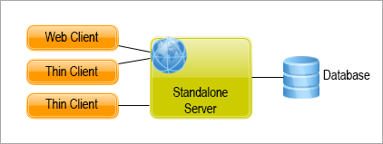
Importing a Configuration from an Infobase into a New Project on a Standalone Server
-
Drag the infobase from the Infobases panel to the Navigator panel.
-
In the Import Configuration and Extensions from Infobase dialog, select the checkbox Use Standalone 1C:Enterprise Server.
-
Click Import.
Switch an Existing Application to a Standalone Server
An application linked to a project may or may not use the standalone server to interact with the infobase. You can change the application's deployment, meaning:
-
If the application does not use a standalone server, you can convert it into an application on a standalone server.
-
An application on a standalone server can be converted into an application that operates with the infobase without using a standalone server.
To change the deployment of an existing application, follow these steps:
-
Select the required project in the Navigator panel.
-
In the Applications panel, click Relocate Application in the application’s context menu.
-
In the Server Version field, select the platform version whose standalone server will be used for the application.
-
Click Finish.
Note: If the list for selecting the server version is empty, it means that the 1C:Enterprise Server component is not installed on your computer. The installed server version must match the project version used by this application.
Switching an application to a standalone server and back may be convenient if, for example, during debugging, you frequently switch between 1C:EDT and Designer. Since launching Designer agent can be faster than launching the standalone server, you may switch the application to use Designer agent during debugging, as before. In cases where a full import or a complete configuration update is needed, you can switch the application to a standalone server to take advantage of multi-threaded data processing.
Add an Application on a Standalone Server to a Project
-
Select the required project in the Navigator panel.
-
In the Applications panel, click
 .
. -
Select Application on a Local Standalone 1C:Enterprise Server and click OK.
-
Select the infobase and click Finish.
Run or Debug a Web Client
The standalone server includes a built-in web server, so no additional steps are required to run or debug the web client.
-
Select the required project in the Navigator panel.
-
Click Run As > 1C:Enterprise Web Client or Debug As > 1C:Enterprise Web Client in the project's context menu.
If a suitable launch configuration does not exist, 1C:EDT will automatically create one and launch the web client.
Modify Standalone Server Properties
-
Select the required project in the Navigator panel.
-
In the Applications panel, double-click the standalone server.
1C:EDT will open the standalone server’s configuration file for editing. This is a text-based .yaml file (learn more).
Identify Which Infobase the Standalone Server Uses
The application name on the standalone server always matches the infobase name.
Stop the Standalone Server
When the standalone server is running, it maintains a connection to the infobase. The Run Designer command in the application’s context menu is aware of this and automatically stops the standalone server before launching 1C:Enterprise Designer.
However, if you launch Designer outside of 1C:EDT, the standalone server’s connection to the infobase will prevent it from opening, resulting in a message stating that the infobase is locked by another process.
In this case, you need to manually stop the standalone server before opening the infobase in Designer.
Stop the Standalone Server
- Select the required project in the Navigator panel.
- In the Applications panel, click Stop in the standalone server’s context menu.
Launch Configuration Editor
The Launch Configuration Editor allows you to create new launch and debug configurations and edit existing ones.
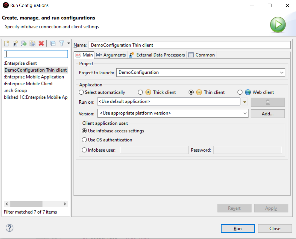
Opening the Launch Configuration Editor
You can open this editor in several ways:
- In the Main Window Command Bar, click:
- (Run As...) Launch Configurations... or
- (Debug As...) Debug Configurations....
- In the Navigator panel, right-click and select:
- Run As Launch Configurations... or
- Debug As Debug Configurations....
Additionally, certain tabs of this editor may open automatically when launching configurations if a suitable configuration for the action is missing. For example, if the project has no linked infobases, explicit selection of the infobase to be launched is required.
The distinction between launch and debug configurations is conditional. The same configuration can be used for both launching and debugging. When a configuration is used as a launch configuration, debug parameters are simply ignored.
Launch configurations are stored per project, and each project has its own set of launch configurations.
Creating a Configuration and Launching an Application
- Open the Launch Configuration Editor.
- Select a group in which you will create a launch configuration.
All configurations are grouped by purpose into several categories:
- 1C:Enterprise Client is a configuration designed for launching client applications.
- 1C:Enterprise Mobile Application is a configuration designed for launching mobile applications on mobile devices directly connected to the computer or on virtual Android devices.
- Published 1C:Enterprise Mobile Application is a configuration designed for launching mobile applications published on the built-in web server or an external web server.
- Connect to 1C:Enterprise Debug Server is a configuration for debugging running client applications.
- Launch Group allows launching multiple applications simultaneously or sequentially.
- Click
 (Create Launch Configuration) in the command bar to create a new configuration.
 - Enter a name for the configuration (Name) so you can distinguish it from other launch configurations.
- The minimum set of parameters required for launching is located in the Main tab:
- Project
- Client Application
- Infobase (1C:EDT application)
- The Project to Launch field is usually pre-filled because 1C:EDT automatically inserts the project selected in the Navigator panel at the time of opening the editor. If you need a different project, select it.
- For the client application, the default option is Select Automatically. The platform will automatically select the client application based on the value of the configuration property Default Launch Mode and the Run Mode property of the user who is running the launch. If you need a different client application, select it.
- For the 1C:EDT application, the default option is Use Default Application. The infobase linked to the current project branch will be launched. If you want to learn more about how 1C:EDT supports Git branching in application development, click here. If you want to use a different infobase, select it.
- Set other launch parameters (for details on tabs and fields, see here).
- To launch the application immediately, click Debug or Run, depending on which command you used to open the editor. The launch configuration will be saved, and the application will start.
To create your own launch configurations, review the conditions for a successful launch and the conditions for successful debugging.
If the application launch fails, check the list of known issues. It describes the causes and solutions for problems you may encounter.
Editing a Configuration
- The easiest way to modify a launch configuration is to select it from the submenu of the (Run As...) command in the Main Window Command Bar and press Ctrl. In this case, 1C:EDT will not start the application but will open the configuration in the editor.
- To modify debug parameters within a launch configuration, follow the same steps to open it from the submenu of the (Debug As...) command. When editing a launch configuration, the Debug Connection tab will be available.
- You can also open the Launch Configuration Editor and choose any available configuration to edit, not just those visible in the menu.
Launch Configuration List
The list of launch configurations is displayed on the left side of the editor.
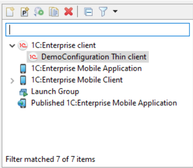
All configurations are grouped by purpose into several categories:
-
1C:Enterprise Client is a configuration designed for launching client applications.
-
1C:Enterprise Mobile Application is a configuration designed for launching mobile applications on mobile devices directly connected to the computer or on virtual Android devices.
-
Published 1C:Enterprise Mobile Application is a configuration designed for launching mobile applications published on the built-in web server or an external web server.
-
Connect to 1C:Enterprise Debug Server is a configuration for debugging running client applications.
-
Launch Group allows launching multiple applications simultaneously or sequentially.
Main Tab
This tab shows the main parameters that are most commonly used when launching an application.
-
Name is the name of the launch configuration, which helps you find it in the interface.
-
Project:
- Project to Run The project that will use this configuration. You can select one of the open projects from the dropdown list.
-
Application:
the 1C:Enterprise client application that will be launched
-
Select Automatically The platform will automatically select the client application based on the value of the configuration property Default Launch Mode and the Run Mode property of the user who is running the launch.
-
Web Client, Thick Client, Thin Client are available options.
-
Run On 1C:EDT application, which will be used for launching:
-
launches the application designated as the default application.
-
One of the available applications launches the selected application.
-
-
Version: You can choose one of the platform versions installed on the computer to launch the client application. A specific version can be selected from the dropdown list, or you can choose a template. If a template is selected, the latest platform version that matches the template will be used. Only platform versions that match or are newer than the selected project version are available.
-
Client application user:
-
Use infobase access settings means that the launch will use the settings saved in 1C:EDT for this infobase (learn more).
-
Use OS authentication allows authentication to be handled by the operating system when the client application connects to the infobase.
-
Infobase User is the username for the infobase. When the client application connects to the infobase, 1C:Enterprise 8 will handle authentication using this username and password.
-
Password is the password for the infobase user.
-
-
Arguments Tab
This tab displays parameters related to the behavior of the client application.
-
Data Separation defines separator values. The string entered in this field must follow separator value rules but should not contain quotation marks enclosing the values. For example, -1,+4. More about data separation is available in Data Separation Mechanism – General Information.
-
Launch Parameter is a custom string available in the global context property LaunchParameter within the 1C:Enterprise language.
-
Connection Settings:
-
Low Connection Speed enables low connection speed mode when selected.
-
Simulate Server Call Delays enables server call delay simulation mode when selected. This mode applies standard values to emulate a GPRS connection:
-
Call Delay (seconds) defines the delay for each server call made by the client application.
-
Data Transmission Delay (seconds per KB) sets the delay when sending data to the server, measured per 100 bytes of transmitted data.
-
Data Reception Delay (seconds per KB) sets the delay when receiving data from the server, measured per 100 bytes of received data.
-
-
Common settings:
-
Suppress Warnings During Launch prevents certain startup messages from appearing if selected. These messages include:
-
"Database configuration does not match the saved configuration. Continue?"
-
"Your computer does not meet the requirements to edit the configuration help. Microsoft Internet Explorer version 6.0 or higher must be installed to edit help."
-
"Your computer does not meet the requirements to edit HTML documents, including help sections. Microsoft Internet Explorer version 6.0 or higher must be installed. Editing HTML documents will be unavailable in this session."
-
-
Display Performance Metrics enables performance metrics display in the client application when selected.
-
Technician Mode is enabled when this checkbox is selected. The client application's interface will display the command Main Menu > Functions for Technical Specialists.... This command provides access to application elements using standard configuration object terms and platform functions without relying on the user interface.
-
-
Service Message Log File specifies the name of the file where service messages will be saved.
- Do Not Clear File Before Launch ensures that new messages are appended to the specified file at the next launch. If this checkbox is not selected, previous messages will be deleted when the application starts.
-
Language settings:
-
System Interface Language determines the language used for platform interface elements, including system menus, dialogs, messages, and help documentation.
-
Session Locale Code: Regional settings of the infobase. Selected from the suggested list, these define the set of regional settings (such as number and date formats, sorting order) that will be used when interacting with the infobase.
-
-
Automated Testing:
-
Do Not Use ensures that the client application does not participate in automated testing.
-
Launch as Testing Manager designates the client application as the testing manager.
-
Launch as Testing Client designates the client application as the testing client.
-
Port Number for Thin and Thick Clients sets the port for communication between the client and the testing manager. The default port is 1538.
-
Identifier for Web Client assigns a unique identifier to the testing client. This identifier is used for the web client when multiple testing clients need to be distinguished while running within the same testing manager application.
-
External Data Processors Tab
This tab displays a list of external processors from the project where the launched project serves as the base.
One of these processors can be selected to open automatically in the debugging or launched application.
Debug Connection Tab
This tab contains settings used for debugging.
-
Debug server:
-
Use the Default Debug Server Suitable for the Launched Infobase
-
For a file-based infobase, a local debug server will be started on the standard port.
-
For a client-server infobase, the debug server deployed within the connected server cluster will be used.
-
-
Use Specified Debug Server allows selecting an active debug server, with connection parameters specified in the following fields.
-
-
Debug connection settings:
-
Debug Server Address should be entered in a format such as
http://debug_host:debug_port/. -
Debug Server Password specifies the password for accessing the debug server if it was started with the parameter
--password=<pwd>. -
Infobase Name sets the name under which the debugger will be registered on the debug server. This setting may be needed when debugging a configuration using data from another client-server infobase with the same configuration. The name of that other infobase can be specified here.
-
General Tab
This tab allows specifying where the launch configuration will be saved, managing standard input and output streams, and setting whether the configuration should be launched in the background.
-
Save as
-
Local File saves the launch configuration locally.
-
Shared File saves the launch configuration at a specified path, such as in the project's workspace, so it is versioned along with other project files.
-
-
Show in Favorites Menu adds the configuration name to the launch or debug menu for quick selection. In the main menu's dropdown lists, favorite configurations appear first, followed by the launch history, and then standard commands.
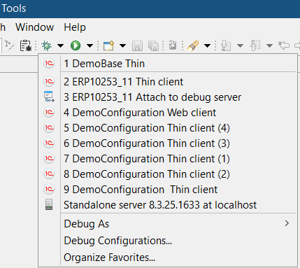
-
Encoding specifies the encoding used for console output.
-
Standard Input and Output:
-
Allocate Console (Required for Input) ensures that output is directed to the Console panel if this checkbox is selected.
-
Input File specifies the file or variables used as the input stream. Buttons Workspace..., File System..., and Variables... allow selecting a file from the workspace, the file system, or a set of variables.
-
Output File specifies the file or variables used as the output stream. Buttons Workspace..., File System..., and Variables... allow selecting a file from the workspace, the file system, or a set of variables.
-
Append ensures that new information is added to the specified file at the next launch. If this checkbox is not selected, the file's previous content will be deleted at the next launch.
-
-
Launch in Background Mode starts the launch configuration in the background when selected.
-
Terminate Child Process When Terminating the Launched Process terminates child processes when the launched process is terminated.
Mobile Application or Mobile Client Tab
This tab appears in configurations designed for launching mobile applications on mobile devices connected to the computer or on Android virtual devices.
-
Project:
- Project to Run The project that will use this configuration. You can select one of the open projects from the dropdown list.
-
Application:
-
Run On 1C:EDT application, which will be used for launching:
-
launches the application designated as the default application.
-
One of the available applications launches the selected application.
-
-
Mobile Platform specifies the version of the developer platform that will be used to launch the mobile application.
-
Reinstall Mobile Platform If this checkbox is selected, the developer mobile platform is reinstalled on the mobile device before launching the mobile application.
-
Reinstall Mobile Client If this checkbox is selected, the developer mobile client platform is reinstalled on the mobile device before launching the mobile application.
-
Reinstall Mobile Client with Offline Mode If this checkbox is selected, the developer mobile client platform with offline mode is reinstalled on the mobile device before launching the mobile application.
-
-
Mobile device:
-
Device defines the physical or virtual Android device where the mobile application will run. You can:
-
 selects an existing device from the dropdown list.
 -
 refreshes the list of virtual devices. For example, after adding a new device in Android SDK.
Tip: The development scenario using virtual and real devices is described here.
refreshes the list of virtual devices. For example, after adding a new device in Android SDK.
Tip: The development scenario using virtual and real devices is described here.
-
-
Publication Tab
This tab is available for configurations of the "Published 1C:Enterprise Mobile Application" type.
-
Project:
- Project to Run The project that will use this configuration. You can select one of the open projects from the dropdown list.
-
Application:
-
Run On 1C:EDT application, which will be used for launching:
-
launches the application designated as the default application.
-
One of the available applications launches the selected application.
-
-
Connect Tab
This tab is available for configurations of the Connect to 1C:Enterprise Debug Server type.
-
Project:
- Project to Run The project that will use this configuration. You can select one of the open projects from the dropdown list.
-
1C:Enterprise Debug Connection Settings:
-
Infobase specifies the infobase to which the client application will connect after launch.
-
Infobase Name specifies the name under which the debugger will register on the remote debug server. This is required when debugging a configuration using data from a different infobase with the same configuration.
-
Debug Server Address specifies the debug server address, for example
http://debug_host:debug_port/. -
Debug Server Password specifies the password for accessing the debug server (if the debug server is started with the parameter
--password=<pwd>).
-
Launching Various 1C:Enterprise Components
Background Tasks, File-Based Mode
In general, when executing background tasks in file-based mode, the following execution schemes may be involved:
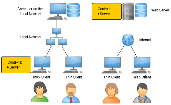
Background tasks always run in the server context. A background task may start due to:
-
Direct execution from the 1C:Enterprise language.
-
Interactive user actions (e.g., running a report).
-
Scheduled execution via a scheduled job.
In any of these cases, at least one client application (thin client, web client, or thick client) must be connected to the infobase:
-
It may directly start the background tasks.
-
It may execute scheduled jobs that, in turn, start background tasks.
-
A connection may be required so that the web server extension module can trigger scheduled jobs.
More details can be found in 1C:Enterprise 8.3. Developer’s Guide.
Launch
You start the client application (thick client, thin client, or web client), and background tasks begin executing.
If a background task is triggered by a scheduled job, it will run according to the schedule.
If a background task is called directly from the 1C:Enterprise language or as a result of user interaction, you need to perform the interactive actions that initiate its execution.
Debugging
Debugging background tasks in file-based mode requires additional configuration (learn more).
Important: Background tasks are not supported in sessions established via external connection in file-based mode (see 1C:Enterprise documentation). If you want to run and debug background tasks through an external connection, use client-server mode.
Background Tasks in Client-Server Mode
When executing background tasks in client-server mode, the following execution schemes may be involved:
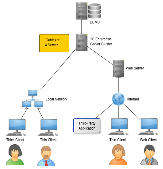
Background tasks always run in the server context. A background task may start due to:
-
Direct execution from the 1C:Enterprise language.
-
User interaction (for example, running a report).
-
Scheduled execution via a scheduled job.
In the first case, execution in the 1C:Enterprise language can begin either in one of the client applications or due to a request from an external application (such as to published web services or HTTP services).
In the second case, background tasks are initiated by platform mechanisms embedded in client applications.
In the third case, the server cluster starts scheduled jobs according to the schedule, regardless of whether client applications are connected.
Launch
If a background task is triggered by a scheduled job, no additional actions are required. It will run automatically as long as the server cluster is running.
If a background task is called directly from the 1C:Enterprise language, you need to perform the interactive actions that initiate its execution or start an external application that triggers it.
Debugging
Debugging background tasks in client-server mode requires additional configuration (learn more).
External Connection
Important: External connections (COM connections) are supported only on Windows.
An external application interacts with the infobase via an external connection (COM connection) as follows:
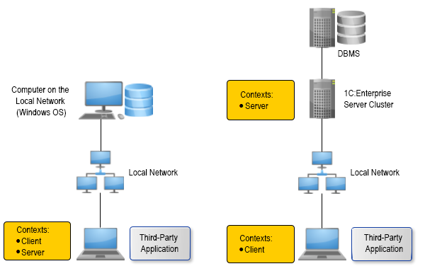
A COM object class, V83.COMConnector, is registered on a computer within a local network. The external application creates a V83.COMConnector COM object and uses it to establish an external connection with a file-based or client-server infobase within the same network.
When the connection is established, the external connection module of the infobase starts executing. For a file-based infobase, the code in the 1C:Enterprise language runs on the computer where the V83.COMConnector object is created (both in the client and server contexts). For a client-server infobase, the code in the client context runs on the computer where the COM object V83.COMConnector is created, while the code in the server context runs on a computer in the server cluster.
Launch
The 1C:Enterprise platform component used in these scenarios includes the `comcntr.dll` library. This library enables external connections. It is registered automatically when the platform is installed.
Troubleshooting: If the user installing the platform has restricted permissions, the library may not be registered. In this case, you can manually register it by running the command prompt as an administrator and executing:
regsvr32 comcntr.dllThe `comcntr.dll` library is located in the platform's binary directory, for example, `C:\Program Files\1cv8\8.3.14.1779\bin`.
You start the external application and perform actions that establish an external connection with the infobase. This launches a COM server, which executes code in the 1C:Enterprise language.
Important: In file-based mode, background tasks are not supported in sessions established through an external connection (see 1C:Enterprise documentation). If you want to run and debug background tasks through an external connection, use client-server mode.
Debugging
Debugging an external connection requires additional configuration.
Web services
When executing web services, the following execution schemes may be involved:
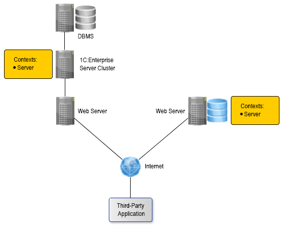
Web services always run in the server context. Execution begins when an external application calls a web service operation published on a web server. A web service can be published for both file-based and client-server infobases.
For a file-based infobase, it is located on the same computer as the web server. On this computer, the web server extension module creates a specialized server environment where the 1C:Enterprise language code is executed.
For a client-server infobase, the code in the 1C:Enterprise language is executed on the computer hosting the server cluster.
Launch
You create a web service in the configuration and update the publication of the infobase on the web server whenever the web service structure changes.
Then, you start the external application and perform actions that invoke the web service operation. As a result, the 1C:Enterprise language code in the operation handler is executed.
In a file-based mode, the code runs as long as the web server is running, while in a client-server mode, it runs as long as the server cluster is running.
Debugging
Debugging web services requires additional configuration (learn more).
HTTP Services
In general, when executing HTTP services, the following execution schemes may be involved:
HTTP services always run in the server context. An HTTP service is executed when an external application calls a method of the HTTP service published on a web server. An HTTP service can be published for both a file-based and a client-server infobase.
For a file-based infobase, it is located on the same computer as the web server. On this computer, the web server extension module creates a specialized server environment where the 1C:Enterprise language code is executed.
For a client-server infobase, the code in the 1C:Enterprise language is executed on the computer hosting the server cluster.
Launch
You create an HTTP service in the configuration and publish the infobase on the web server.
Then, you launch an external application and perform actions that result in calling an HTTP service method. As a result, the code written in the 1C:Enterprise language within the handler of this method is executed.
In a file-based mode, the code runs as long as the web server is running, while in a client-server mode, it runs as long as the server cluster is running.
Debugging
Debugging HTTP services requires additional configuration (learn more).
Standard OData Interface
In general, when interacting with the standard OData interface, the following execution schemes may be involved:
The OData interface allows modifying data in the infobase, meaning that calling its methods can result in writing objects and, consequently, executing event handlers in the 1C:Enterprise language. All handlers related to data modification are executed in the server context. The OData interface can be published on a web server for both a file-based and a client-server infobase.
For a file-based infobase, it is located on the same computer as the web server. On this computer, the web server extension module creates a specialized server environment where the 1C:Enterprise language code is executed.
For a client-server infobase, the code in the 1C:Enterprise language is executed on the computer hosting the server cluster.
Launch
You publish the infobase on the web server. Then, for example, you create an external data processor and execute it once to specify which configuration objects will be accessible via the OData interface. For this, the 1C:Enterprise language provides the method SetStandardODataInterfaceContent().
Then, you launch an external application and perform actions that result in calling an OData interface method. This may trigger the execution of code written in the 1C:Enterprise language related to data modification.
In a file-based mode, the code runs as long as the web server is running, while in a client-server mode, it runs as long as the server cluster is running.
Debugging
Debugging the OData interface requires additional configuration (learn more).
Client Application Launch Modes in 1C:Enterprise
Automated testing
The 1C:Enterprise platform allows automated application testing. Automated testing is a process that simulates user interactions and verifies the results.
User actions are simulated using 1C:Enterprise language objects that provide access to the logical model of the client application's interface and form elements.
Automated testing involves two client applications. One is the testing manager, where the test algorithm runs. The other is the testing client, which reproduces user interactions.
To launch an application in one of these modes, specific settings must be configured in the launch configuration.
More details are available in the 1C:Enterprise documentation.
Performance Metrics
Performance Metrics is one of the development tools. In real-time, in 1C:Enterprise mode, it displays information about the number and duration of server calls as well as the volume of transmitted and received data. This allows developers to reproduce specific user actions and immediately see how often the server was called and how much data was transferred and received.
Performance metrics display settings can be customized. You can view the history of current and accumulated metrics, adjust the displayed indicators, and choose different measurement methods.
More details are available in the 1C:Enterprise documentation.
Low-Speed Connection Mode
Low-Speed Connection Mode is a special mode for client applications that access the infobase via HTTP or HTTPS over a low-bandwidth internet connection (e.g., GPRS).
This mode is available for both the thin client and the web client. It can be specified when launching the client application, or it can be set at the infobase level. In the latter case, client applications connecting to this infobase will use this mode unless another option is explicitly specified at launch.
The main goal of low-speed connection mode is to reduce overhead by minimizing the number of server requests. This is achieved by bundling multiple requests into a single package, preloading potentially needed data, and omitting certain non-essential information. As a result, even over low-bandwidth connections, the platform provides acceptable performance for users.
More details are available in the 1C:Enterprise documentation.
Server Call Delay Simulation Mode
Server Call Delay Simulation Mode allows you to evaluate the actual application performance under real network conditions.
No special internet connection is required. Simply enabling this mode makes the platform (even in file-based mode on a local computer) simulate the delays typical of real network conditions.
Server call delay simulation mode can be enabled or disabled while the client application is running. A session operating in this mode will display a special indicator in the information panel. It is shown as a "handbrake" icon.
When server call delay simulation mode is enabled, the platform applies standard delays designed to mimic a mobile internet connection (e.g., GPRS): Call delay: 1 second. Data transmission delay: 0.45 seconds. Data reception delay: 0.15 seconds. If needed, you can specify custom delay values.
More details are available in the 1C:Enterprise documentation.
Chapter 10. Debugging Applications
Advanced Debugging Features
During debugging, you can use a wide range of features implemented in various 1C:EDT tools:
-
You can see the results of integrated debugging directly in the module text, including the values of the module's local variables.
-
By hovering the cursor over identifiers, you can see their values in a tooltip. Complex values are shown as a tree
-
You can view values in the Variables panel as well as in the specialized Values panel. The Values panel conveniently displays the contents of collections.
-
It is possible to modify variable values directly during debugging.
-
Breakpoints can be exported and imported for example, to ask a colleague to fix errors that occur at these points
-
You can run applications on a remote computer for debugging, connect debugging to an application already running there.
Different Data for Debugging the Same Configuration
You can debug your application using different sets of data. For example, one dataset (infobase) is small and used for testing, allowing for quick startup and fast performance. Another dataset (infobase) is large and complete, enabling testing under real-world conditions with actual data.
To facilitate this, you can link multiple applications with different infobases to the same project. All linked applications will automatically update according to the project's state.
If you are developing using the Git version control system, 1C:EDT provides an additional service that allows you to automatically use different infobases for different Git branches (learn more).
Debugging via HTTP Protocol
When debugging applications, HTTP is used as the transport protocol. This enables access to debug targets that are not on your computer or local network.
To launch a debugged application, an infobase is required, but the debugger itself does not need a direct connection to retrieve the configuration being debugged. The configuration can be obtained from another source, such as .xml files located in a directory.
Debugging via HTTP Protocol
The debugging architecture operates as follows:
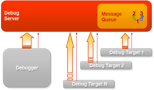
Debugging involves the debugger, debug targets, and the debug server.
There is no direct data exchange between the debugger and the debug targets. All communication occurs through the debug server. This is the central component of the mechanism. The debug server manages a message queue through which the debugger and debug targets exchange information.
Both the debugger and debug targets interact with the debug server via the HTTP protocol. As a result, the location of the debug targets does not matter.
Communication with the debug server is initiated by both the debugger and the debug targets. To facilitate this, additional connections are established. Their main purpose is to check whether new information is available on the debug server. If there is new information, it is retrieved.
Thus, the communication flow is unidirectional. Information is continuously sent from the debug server to the debugger and the debug targets.
debug server
The debug server is a separate application dbgs.exe. It can be found in the task manager.
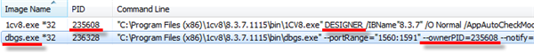
The ownerPID parameter displays the identifier of the application to which this debug server belongs. In this case, it is 1C:Enterprise Designer.
When operating in client-server mode, the ownerPID parameter displays the identifier of the 1C:Enterprise cluster manager.
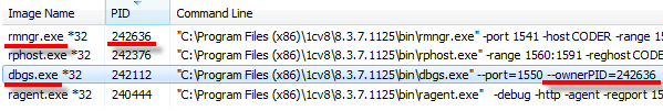
The main functions of the debug server include the following:
- It stores lists of debug targets available for use and lists of connected debug targets.
- It translates 1C:EDT commands for managing the debug process into commands for debug targets, such as stopping or continuing execution.
Connecting Debug Targets
When debugging sessions are launched, applications perform automatic connection of debug targets (both client and server) to the debug server.
Additionally, you can configure automatic connection of debug targets regardless of how they were launched. To enable automatic connection, you can create filters. These filters allow you to specify not only debug targets but also specific users whose sessions you are interested in. If data separation is used, you can also specify the infobase area to be debugged.
Debug targets
During debugging, an application is represented as a set of specific debug targets that execute sequentially or in parallel.
Debug target is an execution thread in 1C:Enterprise language, characterized by the following parameters:
-
Infobase identifier.
-
Type of debug target.
-
Username under which the 1C:Enterprise language code is executed.
-
Session number in use.
The types of debug targets define the context in which program code is executed, the application executing the code, and, in some cases, the source of the code:
-
Thin client is a client context executed by the thin client.
-
Web client is a client context executed by the web client.
-
Thick client is a client context executed by the thick client.
-
Server (file-based mode) is a server context executed by a client application (thin client, web client, or thick client) or the web server extension module. This type of server context execution is used in file-based mode. For easier debugging, some execution threads are classified as a separate type:
- Background Job (File-Based Mode) is an execution thread that originates from background tasks.
-
Server is a server context executed by the server cluster. For easier debugging, some execution threads are classified as a separate type:
- Background task is an execution thread that originates from background tasks.
-
Web service is a server context that originates from Web services. In file-based mode, it is executed by the web server extension module. In client-server mode, it is executed by the server cluster.
-
HTTP service is a server context that originates from HTTP services. In file-based mode, it is executed by the web server extension module. In client-server mode, it is executed by the server cluster.
-
Standard OData interface is a server context that originates from actions run as a result of calling methods in the OData interface. In file-based mode, it is executed by the web server extension module. In client-server mode, it is executed by the server cluster.
-
COM connection refers to contexts executed by the COM server when another application interacts with the infobase through an external connection.
-
In file-based mode, this includes both client and server contexts.
-
In client-server mode, this includes the client context. The server context is executed by the server cluster and is available in debug targets of type Server.
-
-
Client (mobile application) is a client context executed by the mobile platform application.
-
Server (mobile application) is a server context executed by the mobile application. For easier debugging, some execution threads are classified as a separate type:
- Background Job (Mobile Application) is an execution thread that originates from background tasks.
-
Mobile client is a client context executed by the mobile client.
To debug an object, it must be connected. Some debug targets connect automatically, while for others, automatic connection must be explicitly specified.
This approach allows you to exclude debug targets that are not related to the debugged algorithm but are constantly executing, such as background tasks. Additionally, in remote debugging, it allows debugging only the code executed by a specific user.
Debug Perspective
The Debug perspective is the main workspace for debugging applications.
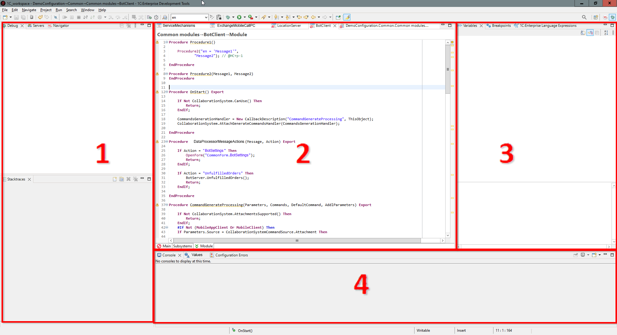
This perspective opens automatically when the execution of 1C:Enterprise language stops at a breakpoint.
Opening the Debug Perspective
You can open the Debug perspective in several ways:
- In the perspective panel, click (Open Perspective), then select Debug.
- In the main menu, click Window > Perspective > Open Perspective > Other... > Debug.
The default Debug perspective includes the following elements:
-
Panels.
-
Debug displays available debug targets and the current execution stack.
-
Project Structure displays the application's structure as a set of regular files rather than a configuration object tree.
-
Servers is not used when developing 1C:Enterprise applications.
-
Navigator displays a list of applications and their elements being developed in 1C:EDT, including configuration projects, configuration extension projects, and external report and processing projects.
-
-
Editor Area When execution stops in 1C:Enterprise language, the 1C:Enterprise Language Editor opens in this area. In debug mode, it provides additional features to facilitate debugging.
-
Panels.
-
Variables displays all variables available in the module.
-
Breakpoints displays all breakpoints in the current workspace.
-
1C:Enterprise Language Expressions allows you to define various expressions that are evaluated at each debugging step.
-
-
Panels.
-
Console displays information directed to the standard output stream.
-
Values displays collections and objects in a more convenient format.
-
Configuration Errors displays errors and warnings identified by automatic configuration validation.
-
Debug Mode
Debugging applications is only possible in a special mode called debug mode. By default, this mode is disabled for all 1C:Enterprise components for the following reasons:
-
Disabling debugging improves application security.
-
Enabling debug mode increases resource consumption. When debugging is disabled, the infrastructure required for debugging is absent, preventing unnecessary communication with the debugger.
In most common debugging scenarios, 1C:EDT automatically starts 1C:Enterprise components in debug mode. However, some components need to be started in debug mode in advance or pre-configured to allow debugging.
For example, in client-server mode, debug server-side objects requires the server cluster to be running in debug mode. Similarly, debugging Web and HTTP services or a web client requires enabling debugging in their web server publication.
Breakpoints
A breakpoint is a condition that causes execution to stop, allowing you to check program state, variable values, and perform step-by-step debugging.
The simplest breakpoint is associated with a specific module line and contains a line number. Execution stops before executing that line.
More complex conditions can include checking whether an expression is true (e.g., stopping when a variable equals a specified value) or detecting an error occurrence (e.g., stopping on any line if an error occurs).
Once program execution stops, you can inspect variable values, modify them, execute one or more subsequent statements, view the call stack (the sequence of method executions leading to this point), and more.
Step Execution
After execution stops at a breakpoint, you can continue executing program code one instruction at a time, step by step, or in blocks, either skipping over called methods or stepping into them.
During step-by-step execution, stopping occurs automatically based on the selected command. If a breakpoint is encountered during the execution of multiple instructions, execution stops at the breakpoint rather than at the next expected stop point.
For more details on step-by-step execution, refer to the 1C:Enterprise Documentation.
Debugging Setup
Configuring Debugging for Client Applications
Thin Client on a Local Network, File-Based Mode
Setup
No special configuration is required.
Debugging Execution
- Launch the thin client in debug mode.
- Debug the following objects (they are connected automatically):
- Thin Client
- Server (File-Based Mode).
Thin Client on a Local Network, Client-Server Mode
Setup
The server cluster must be running in debug mode. Otherwise, you will not be able to debug the code executed in the server context.
Instructions for starting the cluster in debug mode can be found here.
Debugging Execution
- Launch the thin client in debug mode.
- Debug the following objects (they are connected automatically):
- Thin Client
- Server.
Web Client, File-Based Mode
Setup
- Debugging must be enabled in the web server publication of the infobase.
Instructions for enabling it can be found here.
- To select the browser that will be used for debugging, click Window > Settings > General > Web Browser > Use External Browser, select the desired browser, and click Apply and Close.
Debugging Execution
- Launch the web client in debug mode.
- Debug the following objects (they are connected automatically):
- Web Client
- Server (file-based mode).
More details on debugging the web client can be found in the 1C:Enterprise documentation.
Web Client, Client-Server Mode
Setup
- Debugging must be enabled in the web server publication of the infobase.
Instructions for enabling it can be found here.
- The server cluster must be running in debug mode. Otherwise, you will not be able to debug the code executed in the server context.
Instructions for starting the cluster in debug mode can be found here.
- To select the browser that will be used for debugging, click Window > Settings > General > Web Browser > Use External Browser, select the desired browser, and click Apply and Close.
Debugging Execution
- Launch the web client in debug mode.
- Debug the following objects (they are connected automatically):
- Web Client
- Server.
Thick Client, File-Based Mode
Setup
No special configuration is required.
Debugging Execution
- Launch the thick client in debug mode.
- Debug the following objects (they are connected automatically):
- Thick Client
- Server (file-based mode)
Thick Client, Client-Server Mode
Setup
The server cluster must be running in debug mode. Otherwise, you will not be able to debug the code executed in the server context.
Instructions for starting the cluster in debug mode can be found here.
Debugging Execution
- Launch the thick client in debug mode.
- Debug the following objects (they are connected automatically):
- Thick Client
- Server.
Configuring Debugging for Various Components
Background Tasks in File-Based Mode
If you want to debug background tasks using the web client, first ensure that debugging is enabled in the web server publication of the infobase. Instructions for enabling debugging in the publication can be found here.
Debugging Setup
To debug background tasks in file-based mode, you need to enable automatic connection of the debug target Background Job (File-Based Mode) once. Instructions on how to do this can be found here.
Debugging Execution
- Start any client application in debug mode (thin client, web client, or thick client) for the infobase where the background tasks should run.
- Perform interactive actions that trigger the background task, or wait for the scheduled job to start.
- Debug the object, which is Background Job (File-Based Mode).
Troubleshooting: Background tasks are not supported in sessions established via external connection in file-based mode (see 1C:Enterprise documentation). If you need to debug background tasks through an external connection, use the client-server mode: Background Tasks in Client-Server Mode.
Background Tasks in Client-Server Mode
If you want to debug background tasks using the web client, first ensure that debugging is enabled in the web server publication of the infobase. Instructions for enabling debugging in the publication can be found here.
Ensure that the server cluster is running in debug mode. Otherwise, you will not be able to debug the code executed in the server context. Instructions for starting the cluster in debug mode can be found here.
Debugging Setup
To debug background tasks in client-server mode, you need to enable automatic connection of the debug target background task once. Instructions on how to do this can be found here.
Debugging Execution
- Start any client application in debug mode (thin client, web client, or thick client) for the infobase where the background tasks should run.
- Perform interactive actions that trigger the background task, or wait for the scheduled job to start.
- Debug the object, which is background task.
Web services
If you are using client-server mode, ensure that the server cluster is running in debug mode. Otherwise, you will not be able to debug the code executed in the server context. Instructions for starting the cluster in debug mode can be found here.
Ensure that debugging is enabled in the web server publication of the infobase. Instructions for enabling debugging in the publication can be found here.
Debugging Setup
To debug web services, you need to enable automatic connection of the debug target. This is Web Service, and it needs to be enabled once. Instructions on how to do this can be found here.
Debugging Execution
- Launch any client application in debug mode (thin client, web client, or thick client) for the infobase where the web services should run.
- Launch an external application and perform actions that invoke a web service operation.
- Debug the object, which is Web Service.
More details on web service debugging can be found in 1C:Enterprise documentation.
HTTP Services
If you are using client-server mode, ensure that the server cluster is running in debug mode. Otherwise, you will not be able to debug the code executed in the server context. Instructions for starting the cluster in debug mode can be found here.
Ensure that debugging is enabled in the web server publication of the infobase. Instructions for enabling debugging in the publication can be found here.
Debugging Setup
To debug HTTP services, you need to enable automatic connection of the debug target. This is HTTP Service, and it needs to be enabled once. Instructions on how to do this can be found here.
Debugging Execution
- Launch any client application in debug mode (thin client, web client, or thick client) for the infobase where the HTTP service should run.
- Launch an external application and perform actions that invoke an HTTP service method.
- Debug the object, which is HTTP Service.
More details on HTTP service debugging can be found in 1C:Enterprise documentation.
Standard OData Interface
If you are using client-server mode, ensure that the server cluster is running in debug mode. Otherwise, you will not be able to debug the code executed in the server context. Instructions for starting the cluster in debug mode can be found here.
Ensure that debugging is enabled in the web server publication of the infobase. Instructions for enabling debugging in the publication can be found here.
Debugging Setup
To debug code executed as a result of calling methods from the OData interface, you need to enable automatic connection of the debug target Standard OData Interface once. Instructions on how to do this can be found here.
Debugging Execution
- Launch any client application in debug mode (thin client, web client, or thick client) for the infobase where the OData interface is published.
- Launch an external application and perform actions that invoke an OData interface method.
- Debug the object, which is Standard OData Interface.
More details on OData interface debugging can be found in 1C:Enterprise documentation.
External Connection in file-based mode
If you want to debug an external connection using the web client, first ensure that debugging is enabled in the web server publication of the infobase. Instructions for enabling debugging in the publication can be found here.
Debugging Setup
To perform debugging, the following conditions must be met:
- Debugging for the external connection must be enabled in the
comcntrcfg.xmlfile. Instructions for this can be found here. - A launch configuration must be created using the same local debug server port specified in the
comcntrcfg.xmlfile. Instructions on how to do this can be found here. - Automatic connection must be enabled for the debug target, which is COM Connection. Instructions on how to do this can be found here.
Debugging Execution
- Launch the launch configuration you created in debug mode for the infobase to which the external connection will be established.
- Launch an external application and perform actions that should establish the external connection.
- Debug the object, which is COM Connection.
More details on debugging external connections can be found in 1C:Enterprise documentation.
Troubleshooting: This mode does not support background tasks. More details are available in 1C:Enterprise documentation. If you need to debug background tasks over an external connection, use client-server mode.
External Connection in Client-Server Mode
If you want to debug an external connection using the web client, first ensure that debugging is enabled in the web server publication of the infobase. Instructions for enabling debugging in the publication can be found here.
Ensure that the server cluster is running in debug mode. Otherwise, you will not be able to debug the code executed in the server context. Instructions for starting the cluster in debug mode can be found here.
Debugging Setup
To perform debugging, the following conditions must be met:
- Debugging for the external connection must be enabled in the
comcntrcfg.xmlfile. Instructions for this can be found here. - A launch configuration must be created using the same local debug server port specified in the
comcntrcfg.xmlfile. Instructions on how to do this can be found here. - Automatic connection must be enabled for the debug target, which is COM Connection. Instructions on how to do this can be found here.
Debugging Execution
- Launch the launch configuration you created in debug mode for the infobase to which the external connection will be established.
- Launch an external application and perform actions that should establish the external connection.
- Debug the items:
- COM Connection
- Server
More details on debugging external connections can be found in 1C:Enterprise documentation.
Debug Targets Connection
Standard Connection of Debug Targets
To debug a debug target, it must be connected. When an application is launched in debug mode, not all debug targets connect automatically.
If you launch a client application in debug mode from 1C:EDT, the following types of debug targets always connect automatically:
-
Client debug targets related to the launched application:
-
Thick Client
-
Thin Client
-
Web Client (debugging must be enabled in advance in the publication of the infobase on the web server).
-
Client (mobile application).
-
Mobile Client.
-
-
Server-side debug target (if using the client-server mode, the server cluster must be started in debug mode):
-
Server.
-
Server (file-based mode).
-
Server (mobile application).
-
Standalone Server (mobile client with offline mode).
-
Debug targets of these types are connected only when the code is executed under the user account selected for launching the application.
Tip: If you need to debug, for example, server-side debug targets that operate under different user accounts, use debug target filters.
Other debug targets are not automatically connected by default. This is because these debug targets are not initiated by the running application but by external entities. Their execution may start at any time and at varying intervals, which could interfere with the debugging process in the application. For this reason, you must decide whether to debug these items and manually enable their automatic connection:
-
COM Connection.
-
Web Service.
-
HTTP Service.
-
Standard OData Interface.
-
background task.
-
Background Job (File-Based Mode).
-
Background Job (Mobile Application).
Configuring Automatic Connection of Debug Targets
For 1C:EDT to configure automatic connection for debug targets that are not connected by default, it must first connect to the debug server and retrieve the necessary debug target data.
Therefore, the first steps are:
-
Launch the application in debug mode.
-
Switch to the Debug perspective.
-
Select the debugging process
in the Debug panel.
There are two ways to configure automatic connection of debug targets: a simple method and an advanced method. The simple method, selecting debug target types, allows for quick configuration, while the advanced method, creating debug target filters, provides greater precision.
Selecting Debug Target Types
This method is useful when you are launching the client application and want to debug background tasks, Web or HTTP services, external connections, or calls through the OData interface. Simply select the type of debug target you need.
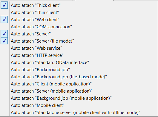
You can access this list in the Debug perspective (when the application is running in debug mode):
- From the Main Window Command Bar by clicking the list button (Configure Debug Targets).
- From the main menu by selecting Run > Configure Debug Targets.
1C:EDT saves your selection in the workspace settings, so you only need to configure it once. As soon as execution reaches a breakpoint in the selected debug target type, execution will stop.
Tip: If execution of the debug target’s code starts at application launch, restart the debug session after selecting debug target types.
Selecting debug target types may not always be convenient. For example, if other users are also using the infobase, debug targets of the selected type will be connected for all users, not just you. In such cases, you can disable the debug target type in this menu and create a filter that specifies only your user account, using the method described below.
Creating Debug Target Filters
This method is useful for remote debugging of multi-user applications or applications that use data separation. You can create one or multiple filters, specifying not only the debug target type but also the user accounts under which the code should be executed.
To open the debug target filter configuration dialog:
- From the Main Window Command Bar by clicking the settings icon **[Configure Debug Targets](#настройка-предметов-отладки)**.
- From the Debug panel by clicking
 > 1C:Enterprise Platform > Configure Debug Targets in the command bar.
You can enable or disable specific filters, allowing you to adjust the debugging scope as needed.
Combining Selected Debug Targets and Debug Target Filters
Selected debug target types and debug target filters are combined using the "OR" operator. This means that a debug target will be automatically connected if it matches one of the selected debug target types OR meets one of the enabled filters.
Starting the Server Cluster in Debug Mode
By default, after installing the 1C:Enterprise platform, the server cluster starts in normal operation mode without debugging capabilities.
To enable debugging of the server context, the cluster must be restarted in debug mode. How to do this for different installation methods and operating systems is described in the 1C:Enterprise Documentation.
Below is a scenario for restarting the cluster when it is running as a Windows service.
How to Determine the Running Cluster Mode
To check the current mode of the cluster, open the service properties for 1C:Enterprise Server Agent.3: To do this:
-
Enter Computer Management in the search field.
-
Open the Computer Management console.
-
In the left panel, expand the Services and Applications node and select Services.
-
In the list of services in the central panel, locate and select the 1C:Enterprise Server Agent.3 service.
-
Double-click the selected service to open its properties.
-
Find the Executable file field. If this field contains the -debug parameter, the cluster is running in debug mode. If the parameter is missing, the cluster is running in normal mode.
-
Select the entire line containing the service startup command and copy it to the clipboard. This will be needed later.
.bat Files for Restarting the Cluster
To start the cluster in debug mode, you need to stop the service, re-register it with different parameters, and start it again. Since you may need to perform these actions multiple times, create two .bat files to automate the process: one for launching the cluster in debug mode and another for launching it in normal mode.
For this, use the service startup command copied to the clipboard.
The .bat file for starting in debug mode should look like this:
"C:\Program Files\1cv8\8.3.14.1779\bin\ragent.exe" -stop
 "C:\Program Files\1cv8\8.3.14.1779\bin\ragent.exe" -instsrvc -debug -http -usr .\USR1CV8
 -pwd usrpwd -regport 1541 -port 1540 -range 1560:1591 -d "C:\Program Files\1cv8\srvinfo"
 "C:\Program Files\1cv8\8.3.14.1779\bin\ragent.exe" -start
Note: In the second line, the command is wrapped due to documentation page width limits. However, in the actual .bat file, it must be a single line.
The first line stops the service, the second registers it with debugging enabled, and the third starts it.
Use the correct path to ragent.exe from your startup command. Ensure the values for -regport, -port, and -d match the copied command. The -range parameter specifies the standard port range used by the cluster. The parameters -srvc and -agent present in the copied command should not be used, as they are internal parameters not used in command-line execution.
The three parameters responsible for registering the service in debug mode are -instsrvc, -debug, and -http. These must be included. Additionally, specify the user under which the service will run and the password used during platform installation. In this example, the user is set with -usr (a standard user created by the 1C:Enterprise platform for running the cluster), and the password is set with -pwd (replace “usrpwd” with your actual password).
The .bat file for starting in normal mode should look like this:
"C:\Program Files\1cv8\8.3.14.1779\bin\ragent.exe" -stop
 "C:\Program Files\1cv8\8.3.14.1779\bin\ragent.exe" -instsrvc -usr .\USR1CV8
 -pwd usrpwd -regport 1541 -port 1540 -range 1560:1591 -d "C:\Program Files\1cv8\srvinfo"
 "C:\Program Files\1cv8\8.3.14.1779\bin\ragent.exe" -start
The only difference is that the -debug and -http parameters are omitted from the second line.
Restarting the Cluster
To restart the cluster, simply run the appropriate .bat file. You can check the service status and mode after the restart in the Computer Management console.
Troubleshooting: If the service does not start after running the .bat file, execute it again. If this does not resolve the issue, an error may be occurring when starting the service. To identify the cause, check the Windows error log.
Enabling Debugging in the Infobase Publication on a Web Server
To enable debugging in the web server publication of the infobase, follow these steps:
-
Identify the address of the local debug server. To do this:
-
Select the project you want to debug in the Navigator panel.
-
Launch the thin or thick client in debug mode.
-
Copy the debug server address to the clipboard. Click Copy Stack in the context menu of the Debug panel.
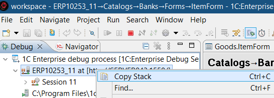
-
End the debugging session. Click Terminate All in the context menu of the Debug panel.
-
-
Find the infobase publication on the web server. To do this:
-
Go to the 1C:Enterprise perspective.
-
Select the project you want to debug in the Navigator panel.
-
Click Show Infobase
in the context menu. -
Select the infobase found in the Infobases panel.
-
In the Properties panel, check the Directory field and note the last part of the directory path.
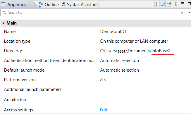
-
Open the Web Servers panel. To open it, click Window > Show View > Other… > 1C:Enterprise > Web Servers.
-
Expand the web server section in this panel and locate the publication.
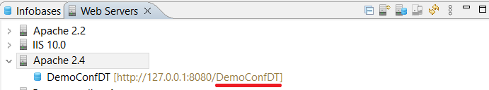
-
Double-click the publication to open it in the editor.
-
-
Enable debugging: To do this:
-
In the Debug group, check Enabled and enter the debug server address in the URL field.
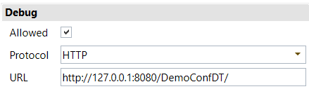
-
Save the changes and confirm synchronization when prompted by selecting Yes.
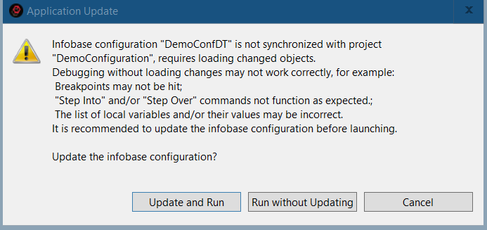
-
Enabling Debugging for External Connections
For the COM server establishing an external connection to run in debug mode, debug parameters must be specified in its configuration file comcntrcfg.xml. By default, after platform installation, the comcntrcfg.xml file does not exist, so you need to create it.
-
Identify the address of the local debug server. To do this:
-
Select the project you want to debug in the Navigator panel.
-
Launch the thin or thick client in debug mode.
-
Copy the debug server address to the clipboard: Click Copy Stack in the context menu of the Debug panel.
-
End the debugging session. Click Terminate All in the context menu of the Debug panel.
-
-
Create the file comcntrcfg.xml. To do this:
-
Navigate to the conf directory of the 1C:Enterprise platform configuration files. For example, in Windows 10, this directory may be C:\Program Files\1cv8\conf.
-
Create a text file named comcntrcfg.xml with the following content:
<config xmlns="http://v8.1c.ru/v8/comcntrcfg">
    <debugconfig debug="true" protocol="http" debuggerURL="http://1C1213FB412D81:45455"/>
</config>
Replace "http://1C1213FB412D81:45455" with the address of your local debug server copied from the clipboard.
-
Make sure to note the port number (in this example, 45455), as it will be needed when creating the launch configuration.
-
More details can be found in 1C:Enterprise documentation.
Creating a Launch Configuration for Debugging on a Specified Port
For debugging certain application components, you may need a launch configuration that uses a local debug server running on a specific port. For example, port 45455.
To create such a configuration, follow these steps:
-
Open an existing launch configuration or create a new one.
-
On the Debug Connection tab:
-
Select the option Use Local Debug Server.
-
Check the box for Specify Debug Server Port.
-
Enter the port number.
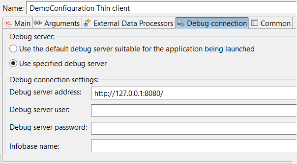
-
Debugging Scenarios
Conditions for Successful Debugging
Certain conditions must be met to successfully debug the applications you are developing.
Debugging the Web Client
- Debugging must be enabled in the web client publication.
Debugging Server Code in the Client-Server Mode
- The server cluster must be running in debug mode.
Web Services
To debug code in a web service module or code that is called from this module, the following conditions must be met:
- Debugging must be enabled in the web service publication.
- Automatic web service connection to debugging must be enabled in 1C:EDT.
HTTP Service
To debug code in an HTTP service module or code that is called from this module, the following conditions must be met:
- Debugging must be enabled in the HTTP service publication.
- Automatic HTTP service connection to debugging must be enabled in 1C:EDT.
Standard OData Interface
To debug code that is executed when the standard OData interface is accessed externally, the following conditions must be met:
- Debugging must be enabled in the OData interface publication.
- Automatic OData interface connection to debugging must be enabled in 1C:EDT.
External Connection
To debug code in an external connection module or code that is called from this module, the following conditions must be met:
- Automatic external connection to debugging must be enabled in 1C:EDT.
background tasks
To debug background tasks, automatic background task connection to debugging must be enabled in 1C:EDT.
Quick Debugging
To launch the client application in debug mode:
-
Select the project in the Navigator panel.
-
Click
(Debug As...) in the Main Window Command Bar.
1C:EDT launches applications using launch configurations.
If this is the first time the project is being launched, 1C:EDT will ask which 1C:Enterprise client application should be debugged.
Then, 1C:EDT will prompt you to create an application by linking the project to an infobase where the configuration contained in the project will be launched. You can either select an existing infobase or create a new one.
After this, the launch configuration will be saved, and the application will start in debug mode.
From then on, when you click ![]() (Debug As...), 1C:EDT will automatically select this launch configuration for your project without additional prompts. If your project uses multiple applications, you can conveniently debug them from the Applications panel by selecting the application you need at that moment.
(Debug As...), 1C:EDT will automatically select this launch configuration for your project without additional prompts. If your project uses multiple applications, you can conveniently debug them from the Applications panel by selecting the application you need at that moment.
Another way to quickly debug an application is to select the client application to be debugged right away. To do this, use the submenu Debug As, which is available in two locations:
-
In the Main Window Command Bar, click
(Debug As...) Debug As. -
In the Navigator panel, click Debug As in the project context menu.
If the application launch fails, check the list of known issues. It describes the causes and solutions for problems you may encounter.
More information on selecting the platform version for launch is available here.
Stopping Execution
For execution to stop at a specific point in the program, the following conditions must be met:
-
The application running the required code fragment must be started in debug mode.
-
The debug target where this code fragment is executed must be connected to the debugger.
-
A breakpoint must be set inside the code fragment.
-
The required actions must be run in the running application, triggering the execution of this code fragment.
When execution reaches the breakpoint, it will stop. After the stop, the Debug perspective will open automatically, and the 1C:Enterprise Language editor will display the module containing the code fragment.
Breakpoints can be set at any time: before starting the application, after it starts, or while it is paused. What matters is that the breakpoint is already set by the time the required code fragment begins execution.
Stopping at a Specified Line
Stopping at a specified line may be useful for checking what parameter values are passed to a called method.
To stop at a particular line in the module, add a breakpoint at that line:
-
Open the required module.
-
Double-click the required line on the vertical ruler or click Breakpoint in the context menu.
A breakpoint
will be added to the line.
Stopping on a Specified Occurrence
When debugging loops, stopping at a specific iteration may be necessary.
To stop at a certain line before it executes for the Nth time, add a breakpoint at that line and edit its properties:
-
Open the required module.
-
Double-click the required line on the vertical ruler or click Breakpoint in the context menu.
A breakpoint
will be added to the line. -
In the breakpoint's context menu, click Breakpoint Properties....
The Properties dialog will open.
-
Check the box for Hit Count and set the value to N.
-
Click Apply and Close.
You can also edit breakpoint properties from the Breakpoints panel:
-
Select the breakpoint in the list.
-
In the details section, check the Hit Count box and enter the value.
Stopping Execution by Variable Value (On Condition)
Stopping execution based on a condition may be useful when the same method processes different objects. One of these objects may have specific characteristics that lead to an incorrect result.
Suppose you want to stop in this method only when it processes this particular "special" object. The object identifier is passed as a method parameter (ObjectID), and you know its value (45209).
To stop inside the method when the condition is met, add a breakpoint to it and edit the breakpoint properties:
-
Open the required module and method.
-
Double-click the required line on the vertical ruler or click Breakpoint in the context menu.
A breakpoint
will be added to the line. -
In the breakpoint's context menu, click Breakpoint Properties....
The Properties dialog will open.
-
Check the box for Conditional and specify the condition, for example:
ObjectID = 45209 -
Click Apply and Close.
- The breakpoint icon will change .
- The breakpoint icon will change
You can also edit breakpoint properties from the Breakpoints panel:
-
Select the breakpoint in the list.
-
In the details section, check the Conditional box and enter the condition.
The breakpoint icon will change
 .
.
Modifying Breakpoint Properties
You can modify the properties of a breakpoint, such as the number of times it should trigger or the condition for stopping.
To modify breakpoint properties in the module or the Breakpoints panel:
-
In the module, right-click the breakpoint and select Breakpoint Properties... from the context menu.
-
In the Breakpoints panel, select the required breakpoint and:
-
Edit its properties in the details section, or
-
Click Breakpoint Properties... in the context menu.
-
Stopping on Any Error
To pause debugging when any error occurs, enable the Stop on Error option. This can be done in two ways.
If debugging has not yet started, open the Debug perspective and click Run > Add Exception Breakpoint... > Stop on Error.
If debugging is already running, you can open the same dialog from the Breakpoints panel by clicking  (Add Breakpoint by 1C:Enterprise Language Exception).
Stopping on a Specific Error
Stopping on a specific error may be useful when you want to halt execution for an error that contains specific text.
For example, the program might generate multiple errors, including one with the message "Division by zero."
To stop when this specific error occurs, add an exception breakpoint and specify the error message text:
-
In the Breakpoints panel, click
(Add Breakpoint by 1C:Enterprise Language Exception) in the command bar.The Stop on Error dialog will open.
-
In the field Stop only on errors containing text, enter part of the error message, such as "division". Click OK.
A breakpoint will be added: Exception Message: [division].
The same actions can be run from the main menu by clicking Run > Add Exception Breakpoint....
Stopping in Event Subscriptions
Event Subscriptions allow you to assign handlers that execute after the standard handler of a certain event in a configuration object is executed. This means multiple handlers assigned through subscriptions can be linked to a single standard event handler.
To stop in all subscriptions for the BeforeWrite event in the Banks catalog, follow these steps:
-
In the Breakpoints panel, click
 (Add Breakpoints by Event) in the command bar.
The Add Breakpoints dialog will open.
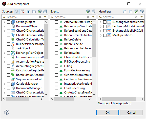
-
In the Sources window, check the box for the object CatalogObject.Banks.

-
The Events window will display the events of the CatalogObject.Banks object that can have subscriptions.
-
The Handlers window will display the modules containing the handlers for these event subscriptions in the CatalogObject.Banks object.
-
-
In the Events window, check the box for the BeforeWrite event.
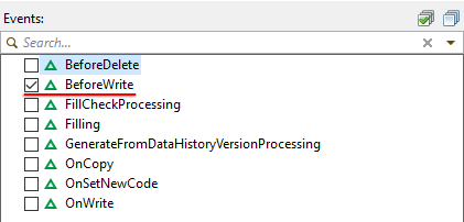
The Handlers window will display the modules that contain handlers for the BeforeWrite event in the CatalogObject.Banks object.
-
In the Handlers window, check all the required modules and click OK.
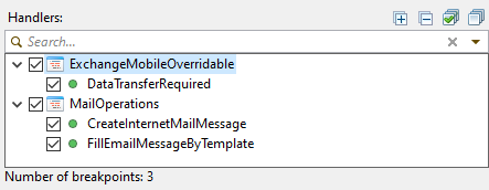
A breakpoint will be set in each of the event handlers (in this example, three handlers).
Similar actions can be run from the All Event Subscriptions editor:
-
In the Navigator panel, right-click configuration and select All Event Subscriptions from the context menu.
The All Event Subscriptions editor will open.
-
Click
(Add Breakpoints by Event) in its command bar.The Add Breakpoints dialog will open.
Stopping Execution on a Program Action
Stopping execution on a program action may be useful when you are unsure which part of the program code is executed in response to a user's action.
To stop execution on a specific program action, such as pressing a button, pause the debugging process and then perform the action:
-
In the running application, perform all actions up to the required one (for example, open a form).
-
Switch to 1C:EDT.
-
In the Debug panel, select the debugging process
 and click Pause in the context menu.
 -
Switch back to the application and perform the action (for example, press a button).
-
Execution will pause at the first executable instruction.
-
The module containing this instruction will open in the 1C:Enterprise Language editor.
-
To pause debugging, you can also select Run > Pause in the main menu.
Managing Breakpoints
Breakpoints Panel
The Breakpoints panel displays all breakpoints in the current workspace.
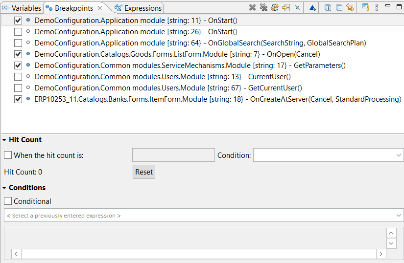
This panel is populated as you add breakpoints.
It is included in the standard layout of the Debug perspective.
Open the Breakpoints Panel
Click Window > Show View > Other… > Debug > Breakpoints in the main menu.
Structure of Information in the Panel
At the top of the panel, there is a list of breakpoints present in the workspace.
The lower part of the panel contains a details area with fields that define conditions for using the selected breakpoint. You can change the position of the details area or hide it entirely.
Legend
 breakpoint enabled
 breakpoint disabled

 inactive breakpoints
- breakpoint conditional
 breakpoint on error
Field Descriptions
Below the breakpoints list is the details area. It contains fields that define conditions for using the selected breakpoint.
- Hit Count if the checkbox is selected, then in the input field you need to specify the ordinal number of the pass through the breakpoint at which execution of the code will stop.
- Conditional if the checkbox is selected, then in the field below, you need to enter a logical expression in 1C:Enterprise language. Each time the breakpoint is reached, this expression is evaluated. Execution stops when the result of the evaluation is True.
Mouse Actions
- A single click on the checkbox field enables or disables the breakpoint.
- A double click on the breakpoint opens the module in the 1C:Enterprise Language Editor and positions it at the line containing the selected breakpoint.
Command Bar
 (Delete Selected Breakpoints) deletes the selected breakpoints.
 (Delete All Breakpoints) deletes all breakpoints.
 (Show Supported Breakpoints for Selected Target Object) If selected, the panel displays only the breakpoints applicable to the debugging language. For example, if you have breakpoints in both 1C:Enterprise language modules and Java modules, only the breakpoints relevant to the 1C:Enterprise language will be shown when debugging 1C:Enterprise language modules.
 (Go to Breakpoint File) opens the module in the 1C:Enterprise Language Editor and positions it at the line containing the selected breakpoint.
 (Skip All Breakpoints) marks all breakpoints as inactive. Inactive breakpoints do not stop program execution during debugging, regardless of whether they are enabled or not. This command is useful when temporarily skipping step-by-step debugging without changing or deleting breakpoints.
- (Add Breakpoints by Event) adds breakpoints to selected event subscription handlers.
- (Expand All) Expands all hierarchy levels in the panel.
- (Collapse All) Collapses all hierarchy levels in the panel down to the first level.
- (Link with Editor) Links the Breakpoints panel with the Debug panel. When program execution stops at a breakpoint in the Debug panel, the respective breakpoint is highlighted in the Breakpoints panel.
- (Add Breakpoint by 1C:Enterprise Language Exception) Adds a breakpoint for any error or for an error containing the specified text.
- (Show Menu) Opens a drop-down menu containing additional commands for the panel.
Layout The submenu contains the following commands:
- Vertical Displays the details area below the list of breakpoints.
- Horizontal Displays the details area to the right of the list of breakpoints.
- Automatic The placement of the details area is automatically chosen (below or to the right) depending on the panel size.
- Breakpoints Panel Only If selected, the details area is not displayed. If cleared, the details area is displayed.
Group By The submenu contains commands that allow you to group the list of breakpoints by project, file, etc.
Sort By The submenu contains commands that allow you to sort the list of breakpoints by name or creation date.
Select Default Working Set... Allows selecting the default working set of breakpoints.
Deselect Default Working Set Cancels the use of the default set of breakpoints.
Working Sets... Opens a dialog that allows you to create, modify, and delete working sets of breakpoints.
Context Menu
- Go to File opens the module in the 1C:Enterprise Language Editor and positions it at the line containing the selected breakpoint.
- Enable enables a disabled breakpoint. During debugging, 1C:EDT will analyze this breakpoint and stop execution if necessary.
- Disable disables a breakpoint. During debugging, 1C:EDT will not analyze this breakpoint and will not stop program execution.
- Disable All disables all breakpoints.
- Delete deletes the selected breakpoints.
- Delete All Triggers Deletes all triggers.
- Delete All deletes all breakpoints.
- Select All Selects all breakpoints.
- Copy Copies the selected breakpoints to the clipboard.
- Insert Inserts breakpoints from the clipboard into the panel.
- Import Breakpoints... imports breakpoints from a `.bkpt` file into the workspace.
- Export Breakpoints... exports breakpoints from the workspace to a `.bkpt` file.
- Breakpoint Properties... Opens a dialog that allows you to change the properties of a breakpoint, such as hit count and stop condition.
Enabling and Disabling Breakpoints
A breakpoint can be enabled or disabled. If a breakpoint is enabled, it is analyzed during execution, and execution may stop at it. If a breakpoint is disabled, it is not analyzed, and execution does not stop.
Disabling a breakpoint can be useful when it is not needed at the current stage of debugging but might be needed later. In that case, you can simply enable it again.
You can disable or enable a breakpoint in the module or in the Breakpoints panel.
-
In the module, click Disable Breakpoint or Enable Breakpoint in the breakpoint's context menu.
-
In the panel, check or uncheck the checkbox next to the breakpoint.
In both cases, the breakpoint icon will change to or .
To disable or enable multiple breakpoints at once:
-
Select them in the Breakpoints panel.
-
Click Disable or Enable in the context menu.
Deleting Breakpoints
You can delete breakpoints when they are no longer needed.
Delete a breakpoint in the module or in the Breakpoints panel.
-
In the module, double click it, and the breakpoint icon will disappear.
-
In the panel, select the breakpoint and click
(Delete Selected Breakpoints) in the command bar or in the context menu.
To delete all breakpoints, click (Delete All Breakpoints) in the command bar or Delete All in the context menu of the Breakpoints panel.
Exporting Breakpoints
You can export breakpoints to a .bkpt file using one of the following methods.
-
In the Breakpoints panel, click Export Breakpoints... in the context menu.
-
In the Breakpoints list, check the boxes for the breakpoints you want to export.
-
In the File field, specify the full path to the .bkpt file where the breakpoints will be exported.
-
Select the Overwrite Existing File Without Warning checkbox if you want to replace the contents of the existing `.bkpt` file without being prompted.
-
Click Finish.
There are other ways to open this dialog:
-
Click File > Export... > Run/Debug > Breakpoints in the main menu.
-
In the Navigator panel, click Export... > Run/Debug > Export Breakpoints in the project context menu.
Importing Breakpoints
Breakpoints can be imported from a .bkpt file using one of the following methods:
-
In the Breakpoints panel, click Import Breakpoints... in the context menu.
-
In the From File field, specify the full path to the .bkpt file containing the breakpoints.
-
Select the checkbox Automatically update existing breakpoints if you want to overwrite the breakpoints in the workspace without confirmation.
-
The checkbox Automatically create breakpoint working sets is not used in 1C:EDT development.
-
On the second step, in the Breakpoints list, select the checkboxes for the breakpoints you want to import.
-
Click Finish.
There are other ways to open this dialog:
-
Click File > Import... > Run/Debug > Breakpoints in the main menu.
-
In the Navigator panel, click Import... > Run/Debug > Breakpoints in the project context menu.
Copying Breakpoints to Clipboard
You can copy the designation of all or some breakpoints to the clipboard as text. To do this:
-
In the Breakpoints panel, select the necessary breakpoints.
-
Click Copy in the context menu.
The text representation of the breakpoints will be saved in the clipboard, for example:
Exception message: [division]
Demo_EDT1.Documents.GoodsReceipt.Module [line: 27] - PostProcessing(Failure, Mode)
Demo_EDT1.Documents.GoodsReceipt.Forms.DocumentForm.Module [line: 126] - OnCreateAtServer(Failure, StandardProcessing)
Demo_EDT1.Catalogs.Products.Forms.ElementForm.Module [line: 11] - OnCreateAtServer(Failure, StandardProcessing)
Configuring the Breakpoint List
Arrangement of the List and Details Panel
Click ![]() (Show Menu) Layout in the command bar.
(Show Menu) Layout in the command bar.
Grouping the List
You can use a linear list of breakpoints or group them by certain criteria. To do this, click ![]() (Show Menu) Group By in the command bar.
(Show Menu) Group By in the command bar.
Not all commands are used in 1C:EDT development, but the following options may be useful:
- Breakpoints a linear list of breakpoints without grouping.
- Projects breakpoints are grouped by projects they belong to.
- Files breakpoints are grouped by files they are located in.
Sorting the List
You can configure the sorting of the breakpoint list. To do this, click ![]() (Show Menu) Sort By in the command bar. The list can be sorted alphabetically by breakpoint name or by creation date.
(Show Menu) Sort By in the command bar. The list can be sorted alphabetically by breakpoint name or by creation date.
Resuming and Ending Execution
Once execution is paused and you have reviewed the necessary values, you can either resume or terminate the application.
Resume Execution After Stopping at a Breakpoint
-
In the Debug panel, select the paused session
 (or debug target
  or method
  ).
). -
Click
 (Resume) in the Main Window Command Bar.
You can also resume execution:
-
From the Debug command bar, click
(Resume). -
From the context menu of the Debug panel, click Resume.
-
From the main menu, select Run > Resume.
Resume Execution Until Selected Line
To resume execution and stop at a specific line:
-
In the module, place the cursor on the line where you want the application to pause execution.
-
In the Debug panel, select the paused session
(or debug target or method ). -
Click Run > Execute to Line in the main menu.
Resume Execution Ignoring Breakpoints
If you need to rerun a debugged action, you can continue execution without stopping at any further breakpoints. This allows you to switch to the application and repeat the action being debugged.
To continue execution in this way:
-
In the Breakpoints panel, click
(Skip All Breakpoints).Breakpoints will be marked as inactive
. -
In the Debug panel, select the paused session
(or debug target or method ). -
Click
(Resume) in the Main Window Command Bar.The application will continue running without stopping at breakpoints.
-
In the Breakpoints panel, click
(Skip All Breakpoints) again.All breakpoints will become active again.
You can also mark breakpoints as inactive from the main menu by selecting Run > Skip All Breakpoints.
Restart Debugging
One possible development scenario is to stop at a breakpoint, analyze variable values, modify the code, and restart debugging to test the new changes.
To restart debugging after stopping at a breakpoint:
-
In the Debug panel, select the launch configuration structure
 .
. -
Click Terminate and Restart in the context menu:
-
The current debugging process will end.
-
If there are unsaved resources, you will be prompted to save them, and the changes will be transferred to the infobase.
-
A new debugging process will start.
-
Terminate a Single Debug Process
-
In the Debug panel, select the debugging process (
or  ).
). -
Click
 (Stop) in the Main Window Command Bar.
Terminate All Debug Processes
- Click Terminate All in the context menu of the Debug panel.
Terminate Debug Process and Clear the Debug Panel
To complete a debug process and remove entries from the Debug panel:
-
In the Debug panel, select the application structure
and the launch configuration structure . -
Click
 Terminate and Remove in the context menu.
Step Execution
Step Into Method
To stop inside a method called in the current line during step execution:
-
In the Debug panel, select the method
. -
Click
 (Step Into) in the context menu.
Program execution will continue and stop at the first instruction of the called method.
If the current instruction does not contain a method call (or contains one, but the method has already been executed), the current instruction will be executed, and execution will stop at the next instruction.
Step into method can also be run from the main menu: Run > Step Into.
Step Over Method
To stop at the instruction following a method call during step execution:
-
In the Debug panel, select the method
. -
Click
 (Step Over) in the context menu.
Program execution will continue and stop at the next instruction. The instructions contained within the called method will be executed without stopping.
If the current instruction does not contain a method call, it will be executed, and execution will stop at the next instruction.
Step over method can also be run from the main menu: Run > Step Over.
Step Out of Method
To step out of the current method during step-by-step execution:
-
In the Debug panel, select the method
. -
Click
 (Step Return) in the context menu.
-
Program execution will continue.
-
All instructions up to the end of the current method will be executed without stopping.
-
Execution will pause at the instruction from which the current method was called.
-
If the current method is the only one in the stack, it will be fully executed, step-by-step debugging will end, and the running application will wait for user actions.
You can also exit the method from the main menu: Run > Step Return.
Jump to Module Containing Breakpoint
Over time, breakpoints become irrelevant and cause unnecessary stops during step-by-step execution. From the Breakpoints panel, you can quickly jump to the module containing a breakpoint to delete or modify it.
To do this, double-click on the breakpoint. The related module will open, and the cursor will be placed on the line containing the selected breakpoint.
Viewing and Modifying Values
Displaying Variable Values in the Module
The values of local variables used in a module can be seen directly in the module's text if integrated debugging is enabled.
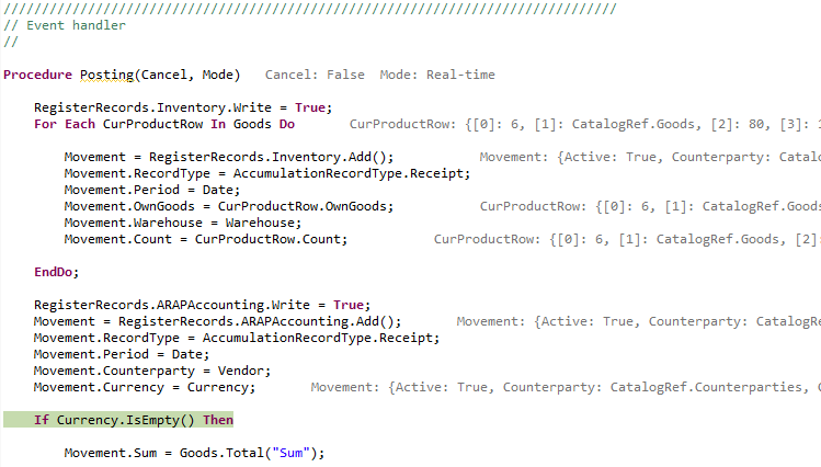
Enable Integrated Debugging
Click ![]() (Integrated Debugging) in the Main Window Command Bar.
(Integrated Debugging) in the Main Window Command Bar.
Change Text Color
Click Window > Preferences... > V8 > Debug > Inline Debug Text Color in the main menu.
Viewing Variable Values
You can quickly view variable values directly in the module. Hover over the identifier of interest, and its value will be displayed in a tooltip.
Objects are displayed in a table with a tree structure, allowing you to expand and examine the object's contents.
Switch to Tree View
Click Window > Preferences... > V8 > Debug > Debug Pop-up Dialog Layout in the main menu.
Add to the 1C:Enterprise Language Expressions Panel
- Select the property of interest.
- Click Watch in the context menu.
In the 1C:Enterprise Language Expressions panel, you can track the value of this property during debugging.
Copy Path
- Select the property of interest.
- Click Copy Path to Variable in the context menu.
This is useful for pasting the path into the program code later.
Evaluating Expressions
To evaluate an expression:
-
Select the expression in the module.
-
Inspect in the context menu.
Objects are displayed in a table with a tree structure, allowing you to expand and examine the object's contents.
Add to the 1C:Enterprise Language Expressions panel
- Select the property of interest.
- Click Watch in the context menu.
In the 1C:Enterprise Language Expressions panel, you can track the value of this property during debugging.
Variables Panel
During debugging, it is often necessary to analyze the values of one or more variables at each debugging step or when moving from one breakpoint to another. For this, the Variables panel is useful.
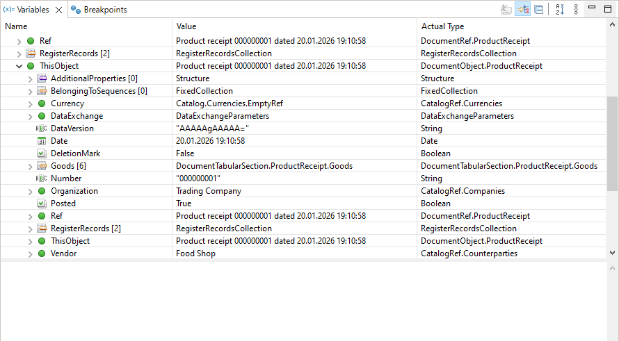
The Variables panel is populated automatically and displays local variables that are within the scope of the instruction where execution is stopped.
Additionally, in a separate Module Properties group, this panel shows the properties of the local context of the module. For example, in an object module, this would be the properties of the object to which the module belongs.
If a variable's value is an object, the panel displays its structure, which can be expanded for detailed viewing.
This panel is part of the standard Debug perspective.
Open the Variables Panel
Click Window > Show View > Other… > Debug > Variables in the main menu.
Structure of Information in the Panel
If a variable has a primitive type such as Number or String, it is displayed in a single line. Otherwise, 1C:EDT displays the variable as a tree, where branches represent properties if it is an object or elements if it is a collection of values.
All variables are divided into three groups:
- The root level displays parameters and variables of the current method where the breakpoint is set. If a variable has not been initialized, its value is displayed as Undefined.
- The Module Properties group displays the local context of the module. For example, in a form module, this group contains all attributes and properties of the form.
- The Module Variables group displays explicitly declared module variables.
When displaying unnamed collections, 1C:EDT uses the Elements group. This group is not a property of 1C:Enterprise language. It is a logical grouping that contains collection elements identified by their indexes.
Below the variables table is an information area that displays a text representation of the value of the variable currently selected in the table. This area is useful for viewing long string values.
Legend
 groups Module Properties and Module Variables
 Type Undefined, as well as in cases where the value is unavailable for reading.
 Type Number.
 Type String.
 Type Date.
 Type Boolean.
 1C:Enterprise language object.
 Unnamed collection (elements can be accessed by index). For example, Array.
 Named collection (elements can be accessed by name or by index). For example, Structure.
 Collection element group.
Columns
- Name is the name of the variable or property
- Value is the value of the variable or property
- Actual Type is the type of the variable or property
Note: You can hide columns Value and Actual Type. In this case, 1C:EDT will display all information in a tree format that includes the name, value, and possibly the type of the value.
Mouse Actions and Dragging
- A single click on a row containing a collection or object displays the collection elements in the Values panel. The Values panel must have linking with the Variables panel enabled. This is enabled by default.
- A single click on a primitive-type value in column Value switches the cell to edit mode, allowing you to change the value.
- A double-click on a collection or object in column Name expands the nested property levels.
- Dragging a column header changes the column order in the panel.
Command Bar
 (Show Type Names) Before the variable name, 1C:EDT displays the type name of its value. The command is available when columns Value and Actual Type are hidden.
 (Show Logical Structure) Not used when developing 1C:Enterprise applications.
- (Collapse All) Collapses all hierarchy levels in the panel down to the first level.
- (Show Menu) Opens a drop-down menu containing additional commands for the panel.
Layout The submenu contains the following commands:
- Vertical Displays the details area below the variables table.
- Horizontal Displays the details area to the right of the variables table.
- Automatic The placement of the details area is automatically chosen (below or to the right) depending on the panel size.
- Variables View Only If selected, the details area is not displayed. If cleared, the details area is displayed.
- Show Columns If selected, columns Value and Actual Type are displayed. If cleared, these columns are hidden.
- Select Columns... Opens a dialog allowing you to select which columns will be displayed in the variables table.
Context Menu of the Variables Table
- Select All Highlights all variables in the panel for subsequent copying.
- Copy Variables Copies the selected variable names, values, and types to the clipboard.
- Find... Searches for variables and properties by name among those displayed in the panel.
- Change Value... opens a dialog for changing the variable value. A new value can be entered for primitive types (Number, String, Boolean, Date) or computed for any type using expression-based modification. For example, `New Structure("key1, key2", "value1", "value2")`.
- Show in Values Displays the collection contents in the Values panel. This command is useful when the Values panel is not linked with the Variables panel.
- Watch adds a variable to the Expressions panel so that its value is tracked during step-by-step debugging. In panel Expressions, you can edit the watched expression and, for example, instead of the variable `ExecutionDate`, track `BeginningOfMonth(ExecutionDate)`.
Context Menu of the Information Area
- Assign Value In the details area, you can enter an expression in the 1C:Enterprise language, for example, `New Structure("key1, key2", "value1", "value2")`. This command assigns the value of this expression to the variable whose value was displayed in the details area.
- Content Assistant Opens the context hint window.
- Cut Copies the selected fragment to the clipboard and removes it from the details area.
- Copy Copies the selected fragment from the details area to the clipboard.
- Insert Inserts content from the clipboard into the details area.
- Select All Selects all text in the details area.
- Find/Replace... Opens a dialog that allows you to find and replace expressions in the details area.
- Wrap Text If this checkbox is selected, long lines in the details area will wrap onto the next line to be viewable without horizontal scrolling. If the checkbox is cleared, long lines will not wrap, and horizontal scrolling will be needed to view them.
- Maximum Text Length... Sets the maximum length of text that will be displayed in the details area. By default, text length is unlimited.
1C:Enterprise Language Expressions Panel
During debugging, it is often useful to track not only local variable values but also object properties and specific expressions used in the code. For this, the 1C:Enterprise Language Expressions panel is useful.
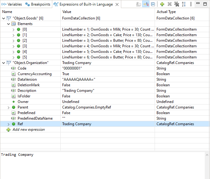
This panel is populated as you create expressions in the Variables panel or add them directly within this panel.
If a variable's value is an object, the panel displays its structure, which can be expanded for detailed viewing.
This panel is part of the standard Debug perspective.
Open the 1C:Enterprise Language Expressions Panel
Click Window > Show View > Other… > 1C:Enterprise > 1C:Enterprise Language Expressions in the main menu.
Create a Watch Expression
You can create a watch expression in different ways:
- Select an expression in the module and click Observation in the context menu.
- Select an expression in the module and drag it into the open 1C:Enterprise Language Expressions panel.
- Evaluate an expression and press Shift+F9.
- Expand an object in the Variables panel, select its property, and click Watch in the context menu.
- Add an expression directly in the 1C:Enterprise Language Expressions panel by clicking:
 Add Expression in the table or
- (Create New Watch Expression) in the command bar
Structure of Information in the Panel
If an expression has a primitive type (Number, String, etc.), 1C:EDT displays the value in a single row. Otherwise, 1C:EDT displays the value as a tree where branches represent properties if it is an object or elements if it is a collection.
The information area below the expressions table displays a text representation of the value of the expression currently selected in the table. This area is useful for viewing long string values.
Legend
 Expression
- Type Undefined, as well as in cases where the value is unavailable for reading.
- Type Number.
- Type String.
- Type Date.
- Type Boolean.
- 1C:Enterprise language object.
- Unnamed collection (elements can be accessed by index). For example, Array.
- Named collection (elements can be accessed by name or by index). For example, Structure.
- Collection element group.
Columns
- Name The expression, variable name, or property. If the expression is a collection, 1C:EDT displays the number of elements in square brackets.
- Value The value of the expression, variable, or property
- Actual Type The type of the expression, variable, or property
Mouse Actions
A single click on an expression highlights the row.
A double click switches the Name field to edit mode, allowing you to modify the expression or add a new one.
Command Bar
- (Show Type Names) 1C:EDT displays the type name of the variable's value before its name. The command is available when columns Value and Actual Type are hidden.
- (Show Logical Structure) Not used when developing 1C:Enterprise applications.
- (Collapse All) Collapses all hierarchy levels in the panel down to the first level.
- (Create New Watch Expression) opens a dialog for adding a new expression.
- (Delete Selected Expressions) Deletes the selected expressions.
- (Delete All Expressions) Deletes all expressions.
- (Show Menu) Opens a drop-down menu containing additional commands for the panel.
Layout The submenu contains the following commands:
- Vertical Displays the details area below the expressions table.
- Horizontal Displays the details area to the right of the expressions table.
- Automatic The placement of the details area is automatically chosen (below or to the right) depending on the panel size.
- Expressions View Only If selected, the details area is not displayed. If cleared, the details area is displayed.
- Show Columns If selected, columns Value and Actual Type are displayed. If cleared, these columns are hidden.
- Select Columns... Opens a dialog allowing you to select which columns will be displayed in the expressions table.
Context Menu of the Expressions Table
- Find... Searches for expressions, variables, and properties by name among those displayed in the panel.
- Evaluate Watched Expression Evaluates an expression. This command is useful when a watched expression is disabled and is not calculated automatically.
- Show in Values Displays the contents of the collection in the Values panel. This command is useful when the Values panel is not linked with the Expressions panel.
Context Menu of the Information Area
- Assign Value In the details area, you can enter an expression in the 1C:Enterprise language, for example, `New Structure("key1, key2", "value1", "value2")`. This command assigns the value of this expression to the variable whose value was displayed in the details area.
- Content Assistant Opens the context hint window.
- Cut Copies the selected fragment to the clipboard and removes it from the details area.
- Copy Copies the selected fragment from the details area to the clipboard.
- Insert Inserts content from the clipboard into the details area.
- Select All Selects all text in the details area.
- Find/Replace... Opens a dialog that allows you to find and replace expressions in the details area.
- Wrap Text If this checkbox is selected, long lines in the details area will wrap onto the next line to be viewable without horizontal scrolling. If the checkbox is cleared, long lines will not wrap, and horizontal scrolling will be needed to view them.
- Maximum Text Length... Sets the maximum length of text that will be displayed in the details area. By default, text length is unlimited.
Values Panel
Values that are collections typically contain a set of elements with identical properties. These values are easier to view in a table format where elements are rows, properties are columns, and property values are at the intersections. For this, use the Values panel.
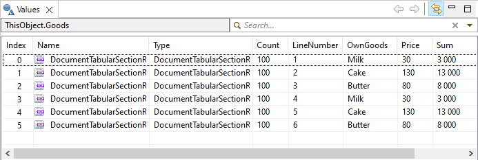
Collections in this panel are displayed in a tabular format with horizontal scrolling. This allows convenient navigation when a collection has many properties.
This panel is part of the standard Debug perspective.
Open the Values Panel
Click Window > Show View > Other… > 1C:Enterprise > Values in the main menu.
Add a Value to the Panel
To display a value in this panel, select a variable containing a collection in the Variables or 1C:Enterprise Language Expressions panel.
If panel synchronization is disabled, use the Show in Values command in the context menu of the Variables and 1C:Enterprise Language Expressions panels.
Disable Panel Synchronization
By default, this panel is linked to the Variables and 1C:Enterprise Language Expressions panels. This allows 1C:EDT to automatically display the contents of the selected collection. To disable this synchronization, click  (Link to Variables/Expressions) in the command bar.
Legend
- Type Undefined, as well as in cases where the value is unavailable for reading.
- Type Number.
- Type String.
- Type Date.
- Type Boolean.
- 1C:Enterprise language object.
- Unnamed collection (elements can be accessed by index). For example, Array.
- Named collection (elements can be accessed by name or by index). For example, Structure.
- Collection element group.
Mouse Actions
A single click on a row containing a collection updates the Values panel, replacing all previous data.
Command Bar
- (Link to Variables/Expressions) Enables or disables linking the Values panel to panel Expressions. If enabled, the expression or collection selected in panel Expressions is automatically displayed in the Values panel.
Context Menu
- Show in Variables highlights the selected variable in the Variables panel. This command is useful when the link is disabled between the Values panel and the Variables panel.
Modifying Variable and Property Values
During step-by-step debugging, you can modify variable values. Use the Variables panel for this:
-
Select the row containing the value you want to change
-
Click the Value cell in that row
Primitive Type Values
Primitive type values (Number, String, Date, Boolean) can be modified directly in the table by clicking the Value cell.
Objects
Values that are objects can be modified using the details area or through a dialog that opens via the Change Value... command in the context menu of the Variables panel.
Modify an Object's Value Using the Details Area
- In the Variables panel, select the variable or property.
- Enter an expression in the details area that produces the required type. Contextual hints are not available in this field. Example:
Catalogs.Contractors.FindByCode("000000015")- In the context menu of the details area, click Assign Value.
The new value will be assigned to the selected variable or property.
Modify an Object's Value Using the Dialog
- In the Variables panel, select the variable or property.
- Click Change Value... in the context menu.
- Select Modification Based on Expressions.
- In the Modification Properties field, enter an expression that produces the required type. Contextual hints can be used while writing the expression. Example:
Catalogs.Contractors.FindByCode("000000015")- Click OK.
The new value will be assigned to the selected variable or property.
System Enumerations and System Value Sets
Values of system enumeration or system value set types can be modified using expressions, similar to object values. Only in this case will it be enough to write the type and use the dot operator to select the desired value.
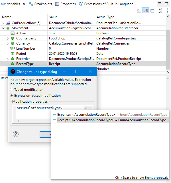
Restrictions When Modifying Values
Some object properties are read-only. Attempting to modify them will result in an error: "The object field is read-only (<property name>)".
Variable values and values of untyped properties, such as a structure element value KeyAndValue.Value, can be assigned values of any type.
Typed property values can only be changed to values of the same type.
Values of properties in the Elements groups cannot be modified, as these groups are not actual properties in 1C:Enterprise language. They serve as logical groupings containing collection elements indexed by their positions.
String-type values String can be changed to values of any other type. However, the existing value type will not change. instead, the new value will be stored as its string representation.
Stack Navigation
When analyzing variable values, it may be necessary to view not only the current method’s context but also the variables of previous methods that called the current one.
To analyze variables in calling methods, navigate through the call stack in the Debug panel.
Select a method of interest. It will open in the 1C:Enterprise Language Editor. At the same time, the Variables panel will automatically display the selected method’s variables, and the 1C:Enterprise Language Expressions panel will recalculate expressions for that method.
Analyzing 1C:Enterprise Language Call Stacks After a Crash
In 1C:Enterprise, the detailed error message includes a call stack of the 1C:Enterprise language code. Compared to Designer, 1C:EDT offers more extensive capabilities for analyzing this stack. Take a look at an example.
Example Call Stack Analysis
When an application crashes, the platform displays a window with a brief error message.
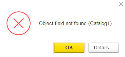
Click Details... to view a detailed error message containing the 1C:Enterprise language call stack.
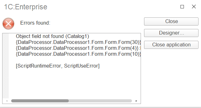
If the application was not running in debug mode, you can copy this stack to the clipboard and add it manually to the Stack Traces panel.
If the application was running in debug mode, click Designer.... The 1C:EDT window will become active, displaying the same message, where you need to click Analyze.
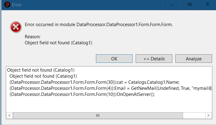
After that, the same stack will appear in a new Stack Traces panel.
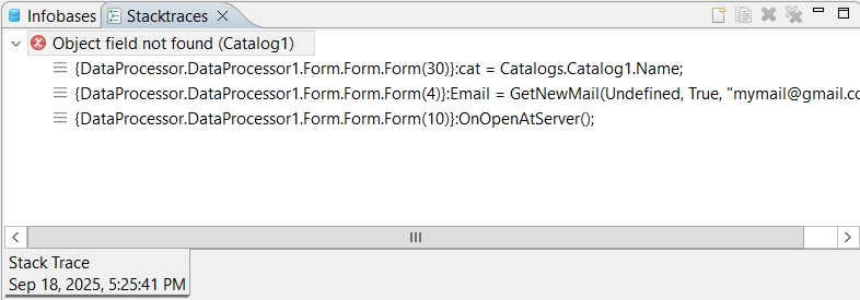
Double-clicking a stack row opens the related module at the specified line.
Stack Traces Panel
The Stack Traces panel allows you to analyze call stacks of 1C:Enterprise language code, such as after a crash.
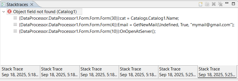
Stacks are preserved between sessions, so they will remain even if you restart 1C:EDT.
This panel is part of the standard Debug perspective.
Opening the Stack Traces Panel
Click Window > Show View > Other... > 1C:Enterprise > Stack Traces in the main menu.
Adding a Trace from the Debug Panel
- Select the debug target branch that contains the relevant call stack .
- Click Copy Stack in the context menu.
- In the Stack Traces panel, click
 (Add Stack Trace) in the command bar.
 - Enter a Title.
- Click OK.
Adding a Trace from the Clipboard
- Click Copy Stack in the context menu.
- In the Stack Traces panel, click (Add Stack Trace) in the command bar.
- Enter a Title.
- Click OK.
Copying a Stack to the Clipboard
- Click
 (Copy) in the command panel.
Command Bar
- (Add Stack Trace) Adds a trace from the clipboard.
- (Copy) Copies a trace to the clipboard.
 (Delete) Deletes the current trace.
 (Delete All) Deletes all traces.
Debug Panel
The Debug panel displays available debug targets and the current call stack.
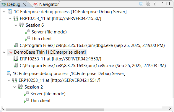
This panel is part of the standard Debug perspective.
Open the Debug Panel
Click Window > Show View > Other… > Debug > Debug in the main window menu.
The list of processes is formed and updated automatically to reflect the current state of running processes.
Structure of Information in the Panel
The information presented in the panel follows a hierarchical structure. At the first hierarchy level, for each debugged application solution, 1C:EDT displays its debugging structure and, if applicable, the structure of the launch configuration used for its startup.
-
Application structure
-
Launch Configuration Structure
Note: The launch configuration structure may not be displayed if, for example, a connection was made to a client application running on a remote computer.
Each of these structures contains a logical representation of the debugging process . Additionally, the application structure contains the physical process of the used debug server, while the launch configuration structure contains the physical process of the running client application.
-
Application structure
-
Debug process
-
 Physical process of the debug server
-
-
Launch configuration structure
-
Debug process
-
Physical process of the client application
-
For the launch configuration, this is a complete structure that does not expand further. In the application structure, more detailed debugging process information is available.
Within the debugging process, multiple sessions may exist. For example, if both a thick client and a thin client were launched for debugging, each will run in its own session.
-
Debug Process
-
 Session 8
 -
Session 10
-
Session 12
-
Inside each session, 1C:EDT displays its debug targets. For example, one session may include a thin client and a server, while another may include a thick client.
-
Debug Process
-
Session 8
-
Debug Target
-
Debug Target
-
-
Session 10
- Debug Target
-
Additionally, when execution stops at a breakpoint within a debugged subject, 1C:EDT displays the call stack of 1C:Enterprise Language methods leading to the breakpoint.
-
Debug Process
-
Session 8
-
Debug Target
-
Method 1
-
Method 2
-
Method 3
-
-
Debug Target
-
-
Legend
-
, , , are active processes.
-
, , are stopped processes.
-
represents the debug structure of a single application.
-
represents the structure of an active launch configuration. It includes the physical process of the client application. The debug configuration structure also includes a logical representation of the debug process involving the client application. The designation includes the name of the launch configuration.

-
represents the logical representation of the debug process for a single application. The designation consists of the project name and the address where the debug server is running.

-
represents a session. The designation includes the session number.

-
represents a debug target. The designation includes the debug target name and the username.

-
represents the executed method. The designation includes the module name, method name, parameter values, and the line number where the method is located.

-
represents the physical process of the debug server or client application. The designation includes the path to the executable file and the start time.

Command Bar
-
(Collapse All) Collapses all hierarchy levels in the panel down to the first level.
-
 (Delete All Completed Runs) Removes all completed runs from the panel.
Note: The following commands appear in the panel if Show Debug Toolbar is enabled. By default, it is disabled.
-
(Resume) Resumes the execution of the module after stopping at a breakpoint.
-
 (Pause) Stops the module execution at the current statement and allows debugging to begin from the next executable line. This command is useful, for example, when analyzing a "looping" module or for stopping execution when the location of the code being executed as a result of an action in the application solution is unknown.
 -
(Stop) Stops module execution and ends the current debug session. Events BeforeExit and OnExit will not be triggered.
-
 (Detach) Disconnects the debugger from the debug target. The command is active when the Debug panel highlights a debug target .
 -
(Step Into) Executes the current instruction and moves to the next. If the current instruction contains a method call, step-by-step execution of that method begins.
-
(Step Over) Executes the current instruction and moves to the next. If the current instruction contains a method call, that method executes in full (not step-by-step).
-
(Step Return) Executes the current instruction, all instructions up to the end of the current method, and moves to the instruction from which the current method was called.
-
 (Drop to Frame) Not used when developing 1C:Enterprise applications. Re-enters the selected call stack.
 -
 (Enable/Disable Step Filters) Not used when developing 1C:Enterprise applications. Enables or disables step filters during debugging.
 -
(Show Menu) Opens a drop-down menu containing additional commands for the panel.
-
Layout The submenu contains the following commands:
-
Automatic The Debug panel automatically switches the information view between a tree structure and a navigation chain when the panel size changes.
-
Tree Displays information in the panel as a tree.
-
Breadcrumbs Displays information in the panel as a navigation chain.
-
Auto-Expand Breadcrumbs If this checkbox is selected, the navigation chain nodes will automatically expand fully when clicked. If the checkbox is cleared, clicking on a navigation chain node will only show the first level of nesting.
-
-
Show Debug on the Toolbar If this checkbox is selected, debug commands are displayed not only in the Main Window Command Bar but also in the Debug panel.
-
Manage Panels... Opens the Run/Debug — Manage Panels parameter group.
-
1C:Enterprise Platform The submenu contains the following commands:
- Configure Debug Targets allows you to create filters that determine which debug targets will be connected automatically. For each debug target, you can also specify a list of users and delimiter values that will automatically connect the item to debugging.
-
Context menu
-
Copy Stack Copies the selected stack lines to the clipboard.
-
Find... Searches among physical processes
, debug processes , application structures  , and launch configuration structures .
 -
Step Into Executes the current instruction and moves to the next. If the current instruction contains a method call, step-by-step execution of that method begins.
-
Step Over Executes the current instruction and moves to the next. If the current instruction contains a method call, that method executes in full (not step-by-step).
-
Step Return Executes the current instruction, all instructions up to the end of the current method, and moves to the instruction from which the current method was called.
-
Use Step Filters Not used when developing 1C:Enterprise applications. Enables or disables step filters during debugging.
-
Resume Resumes the execution of the module after stopping at a breakpoint.
-
Pause Stops the module execution at the current statement and allows debugging to begin from the next executable line. This command is useful, for example, when analyzing a "looping" module or for stopping execution when the location of the code being executed as a result of an action in the application solution is unknown.
-
Stop Stops module execution and ends the current debug session. Events BeforeExit and OnExit will not be triggered.
-
Terminate and Restart Stops module execution, ends the current debug session, and restarts application debugging.
-
Detach Disconnects the debugger from the debug target. The command is active when the Debug panel highlights a debug target
. -
Delete All Completed Removes all completed runs from the panel.
-
Restart Restarts the selected launch configuration.
-
Change 1C:Enterprise Debug Process... opens a dialog to change the selected debug process.
-
Change Source Lookup Path...
-
Terminate and Remove Stops module execution, ends the current debug session, and removes Debugging launch information from the panel.
-
Terminate All Stops execution of all debug processes.
Console Panel
The Console panel displays information directed to the standard output stream and the standard error stream. Additionally, you can enter arbitrary text into the console, which will be sent to the standard input stream.

This panel is part of the standard Debug perspective.
Open the Console Panel
Press Window > Show View > Other… > General > Console in the main menu.
Command Bar
-
 (Terminate) Ends the process associated with the current console.
 -
 (Delete Run) Deletes the current run from the console.
 -
 (Delete All Completed Runs) Deletes all completed runs from the current console.
 -
 (Clear Console) Clears all content from the current console.
 -
 (Disable Scrolling) Prevents vertical scrolling in the current console.
 -
 (Word Wrap) Enables or disables word wrapping in the current console.
 -
 (Show Console on Standard Output Changes) If selected, the console will open over other panels in its group when a new message appears in the standard output stream.
 -
 (Show Console on Standard Error Changes) If selected, the console will open over other panels in its group when a new message appears in the standard error stream.
 -
(Pin Panel) If this button is pressed, the panel will not be closed by other panels in its group.
-
 (Show Selected Console) Opens a list of current consoles and allows you to choose which one you want to display. This command is available only if multiple consoles are open.
 -
 (Open Console) Opens a new console of the selected type.
Context menu
-
Cut Copies the selected fragment to the clipboard and removes it from the console.
-
Copy Copies the selected fragment from the console to the clipboard.
-
Paste Pastes clipboard contents into the console.
-
Select All Selects all console content.
-
Find and Replace... Opens a dialog to find and replace a text fragment in the console.
-
Find Next finds the next occurrence of the selected fragment.
-
Find Previous finds the previous occurrence of the selected fragment.
-
Open Link Follows a hyperlink displayed in the console.
-
Clear Clears all content from the current console.
-
Delete All Completed Deletes all completed runs from the current console.
-
Terminate All Ends all processes.
-
Disable Scrolling Prevents vertical scrolling in the current console.
-
Word Wrap Enables or disables word wrapping in the current console.
-
Preferences... Opens the Console parameter group, which allows you to configure the appearance and behavior of the console.
Console Parameter Group
Open the Console parameter group
You can open the Console parameter group in several ways.
- In the main menu, click Window > Preferences... > Run/Debug > Console
- In the Console panel, press Preferences... in the context menu.
Field Descriptions
- Fixed Console Width If enabled, the console has a fixed width set by the property Maximum Width (Characters). Some applications output long lines in the console, requiring horizontal scrolling. To avoid this, enable the fixed console width. Long lines will then be wrapped automatically. By default, this option is disabled, and the console width is unrestricted.
- Maximum Width (Characters) The maximum width of the console in characters. The default value is 80. Used when the property Fixed Console Width is set.
- Limit Console Output If enabled, the number of characters displayed in the console is limited to the value set in property Console Buffer Size (Characters). When the output exceeds this value, the oldest content is removed. By default, this option is enabled, and console output is limited.
- Console Buffer Size (Characters) The maximum number of characters displayed in the console. The default value is 80,000. Used when the property Limit Console Output is set.
- Visible Tab Size The tab width in characters. The default value is 8.
- Enable Word Wrap if checked, the console wraps text to avoid horizontal scrolling.
- Redirect Output to Standard Output Stream If enabled, when a new message appears in the standard output stream, the console will open on top of other panels in its group. By default, this option is enabled.
- Redirect Output to Standard Error Stream If enabled, when a new message appears in the standard error stream, the console will open on top of other panels in its group. By default, this option is enabled.
- Text Color for Standard Output Stream The color of text displayed in the standard output stream. The default color is black.
- Text Color for Standard Error Stream The color of text displayed in the standard error stream. The default color is red.
- Text Color for Standard Input Stream The color of manually entered text. This text will be sent to the standard input stream. The default color is green.
- Background Color The background color of the console. The default color is white.
- Interpret ASCII Control Characters allows interpreting certain ASCII control characters in the console. Currently, the console can interpret backspace (
\b), carriage return (\r), form feed (\f), vertical tab (\v), and null byte (\0) if enabled. See the next setting for additional carriage return options. - Interpret Carriage Return (
\r) as a Control Character determines how the carriage return is handled when ASCII control character interpretation is enabled. Some operating systems, such as older versions of macOS, use carriage return as a line separator, so it may need to be excluded from ASCII control character interpretation. If disabled, the carriage return will be interpreted as a line separator.
Chapter 11. Team Development and the Git Version Control System
This section covers general collaboration topics and the principles of building and operating the Git version control system.
Git Perspective
The Git perspective is the main workspace for working with the Git version control system.

Open the Git Perspective
You can open the Git perspective in several ways:
- In the Perspective Panel, click (Open Perspective), then Git.
- In the main menu, click Window > Perspective > Open Perspective > Other... > Git.
The standard Git perspective includes the following elements:
- The Git Repositories panel, which serves as the main tool for managing multiple repositories simultaneously.
- The Editor Area, where panels such as Commit View Panel can be opened.
- Panels:
- History, which displays repository resources with a focus on commits.
- Synchronization, which shows differences between resources in the local directory and those in the local or remote branch.
- Git Reflog, which displays the reference log for the selected repository.
- Properties, which shows properties of local and remote repositories selected in the Git Repositories panel.
Configuration Stored as Files
1C:EDT stores configurations as custom format files on disk. This approach provides several technological advantages.
The main benefit is the ability to use external version control systems effortlessly. 1C:EDT has built-in support for Git, allowing immediate and seamless integration.
Thanks to Eclipse plugin technology, other version control systems can also be used. These systems can be utilized for personal archiving and versioning of developments. However, using them for merging changes or team development is not recommended. Without proper adaptation, the default merging of .xml files may not work correctly in the context of 1C:Enterprise. With Git, such adaptation has been implemented, making all its features fully usable.
Licensing Development for Public Repositories
This section briefly outlines the licensing policies of 1C that must be considered when publishing your work in public repositories or using standard libraries provided by 1C.
A custom configuration that does not contain fragments supplied by 1C may be published on GitHub (see Question 62 for details).
However, if your development includes elements provided by 1C (e.g., modifications to a standard configuration), it cannot be published on GitHub (see Question 71 for details).
Specific rules govern the distribution and use of standard libraries supplied by 1C (SSL and others).
Starting from version 3.0.2, SSL has its own license, which must be followed when distributing or using it (see Question 70 for details). 1C plans to gradually release other standard libraries under similar licenses.
The SSL 3.0.2 license can be found in the file %AppData%\1C\1cv8\tmplts\1C\SSL\3_0_2_164\ExtFiles\Docsnews.htm (after installing the configuration template) or on the website (link). The license is also specified in the header of each module included in SSL.
The Attribution 4.0 International (CC BY 4.0) license allows you to distribute (e.g., publish on GitHub), modify, correct, and use SSL 3.0.2 as a basis for your own configurations, including those intended for commercial distribution. However, you must specify the copyright holder (Copyright © 1C-Soft LLC, 2009-2024) and indicate what changes were made if you have modified it.
If a standard library does not have its own license, 1C allows its use only for official users of 1C:Enterprise products with a PROF version or higher, who have an active 1C:ITS agreement, as well as for 1C partners under their contract with 1C (see Question 72 for details).
Git Support in 1C:Enterprise Application Development
Working with Git version control involves frequent branch creation, switching between branches, and launching and debugging applications in each branch. 1C:EDT includes several mechanisms to facilitate the use of Git in 1C:Enterprise application development.
Individual Infobases for Different Branches
A key feature of 1C:Enterprise is that a configuration developed in different branches includes not only executable code but also the data structure definitions it operates on. When running or debugging an application, 1C:EDT always places the current configuration into the infobase linked to the project. If the data structure being placed differs from the one in the infobase, the platform restructures the database.
This ensures that the database structure always matches what the running application expects. However, different branches in Git may contain different configuration objects, requiring individual infobases for each branch to prevent data conflicts.
To simplify and automate the use of individual infobases for Git branches, 1C:EDT includes several enhancements. When a new Git branch is created, 1C:EDT automatically generates a respective infobase. From that point on, switching projects between branches happens seamlessly, with 1C:EDT selecting the appropriate infobase for each branch when launching or debugging.
These enhancements are integrated into several parts of the system:
- For Git branch creation, it is recommended to use the dedicated 1C:EDT command instead of the standard EGit command:
 (Create New Branch...). This command is available in the Navigator panel under the Version Control (Team) group. The command not only creates a Git branch but also links it to a new or existing infobase (learn more).
 - In the launch and debug configuration editor, the default setting for new configurations is Use the default infobase for the project (more details). This means that when you switch the project to another Git branch and decide to run it, 1C:EDT will create a run configuration with the infobase that corresponds to the current Git branch.
- To view the associations between a project, Git branches, and infobases, use the Development panel (learn more).
- For branch deletions and associated infobase removals (learn more), use the context menu command Delete Branch... in the Development panel (learn more).
- Default branch names, infobase creation settings, and collaboration options can be configured in the V8 > Team Development parameter group (learn more).
Optimizing Project Data Storage Format
1C:EDT may change the internal format of .xml project files between versions. If working within the same project branch, no issues arise. When opening an older workspace, the new version of 1C:EDT migrates the project to the updated format if needed.
However, if development occurs across multiple branches or involves multiple developers, an issue may arise. Merging an older branch into master may introduce unexpected modifications beyond your own changes. These discrepancies often result from format changes made in newer 1C:EDT versions. One branch may contain the project in a new format, while another retains the old one. Although no functional differences exist, comparison tools may highlight numerous unnecessary modifications.
To address this, 1C:EDT provides a mechanism for optimizing the project storage format. This feature automatically converts old-format project files to the new format. You can optimize the format interactively in the Project Editor or by running a command in the command-line interface.
When using optimization, consider two key aspects:
- For large projects, the process may take a significant amount of time.
- If a branch contains uncommitted changes, they should be committed before optimization. Committing changes first ensures that modifications introduced by optimization do not obscure your own edits, making code reviews easier.
The book Team Development in 1C:Enterprise Development Tools.
This book provides a comprehensive introduction to Git version control. All Git features and best practices are demonstrated using the 1C:Enterprise Development Tools environment.
If you have never worked with Git, this book is for you. It features a convenient index and search function.
You can view this book on the 1C:EDT portal at this link.
Some sections that may be useful:
Usage Examples
This section provides examples of collaborative application development.
Creating a Remote Repository on GitHub and Placing the Configuration in It
This example demonstrates how to create a free public repository on github.com and version your project in this repository.
Note: If needed, you can use private paid repositories on the same site or choose other services for creating remote repositories, such as SourceForge or Google Cloud Source Repositories.
Tip: It is assumed that you already have a project in 1C:EDT that you are developing. If not, you can:
-
Create a new project with an empty configuration.
-
Import a configuration into a new project from an existing infobase.
The example consists of several parts:
Connect the Project to a Local Repository
Now, you will create a local Git repository on your computer and connect the project to it. The diagram represents it as follows:
-
Open 1C:EDT or switch to it if it is already running.
-
Ensure that you are in the 1C:Enterprise perspective. When this is the case, the perspective panel highlights the
 (1C:Enterprise) icon.
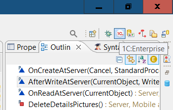
-
If you are in a different perspective, click this icon to switch to the 1C:Enterprise perspective.
-
If the icon is not in the perspective panel, click
 > 1C:Enterprise (default) > Open in the perspective panel.
-
-
For the project that you want to place in the repository, open the Navigator panel, right-click the project, and select Version Control (Team) > Shared Project... from the context menu.
-
Specify the main properties of the local repository that will be created on your computer.
Warning: When creating a local repository, set it up so that the repository directory and the 1C:EDT workspace are not nested within each other. To learn more, read here.
-
In the Repository field, enter the directory where the repository will be stored.
-
Click Finish.
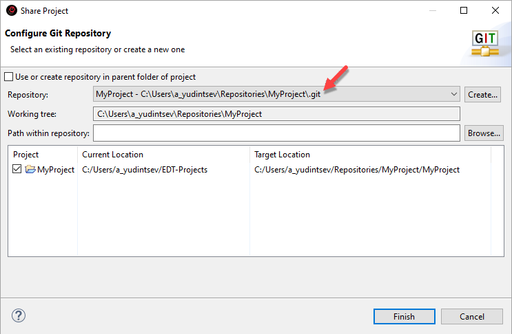
-
-
1C:EDT will move your project to the repository directory. As a result, you will see the following changes:
-
The project’s context menu Version Control (Team) will now include repository-related commands.
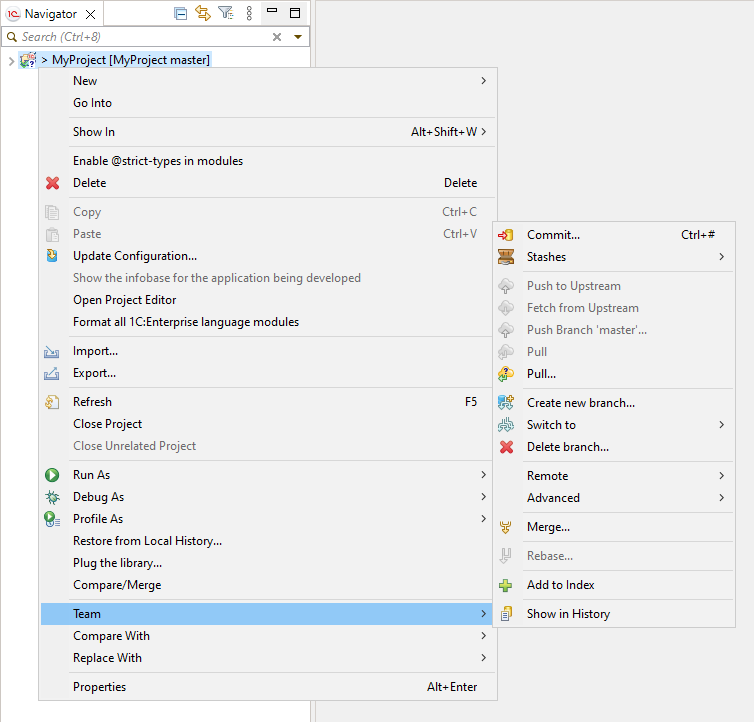
-
Switch to the Git perspective by clicking
> Git > Open in the Perspective panel.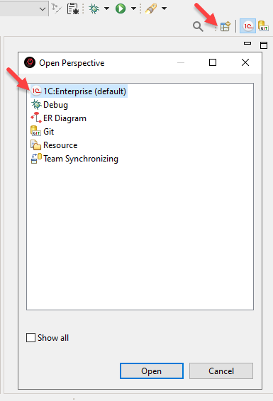
The Git Repositories panel will now display your local repository. The working tree of the repository will contain your project structure and files.
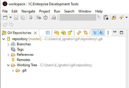
-
-
In the perspective panel, click
(1C:Enterprise) to return to the 1C:Enterprise perspective.
Commit Configuration Changes
Now, you will create the first commit for your project, which will place it in the local repository. The diagram represents it as follows:
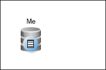
-
Open the Navigator panel, right-click the project connected to the local repository, and select Version Control (Team) > Commit... from the context menu. The Git Staging panel will open, displaying your project files in the Unstaged Changes section.
-
Create a commit:
-
Click
 (Add All Files to Index) in the unstaged changes command bar. After a short time, all files will be moved to the Staged Changes section.
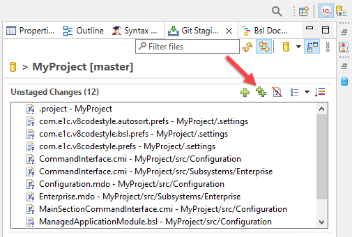
-
In the Commit Message field, enter a comment describing your changes.
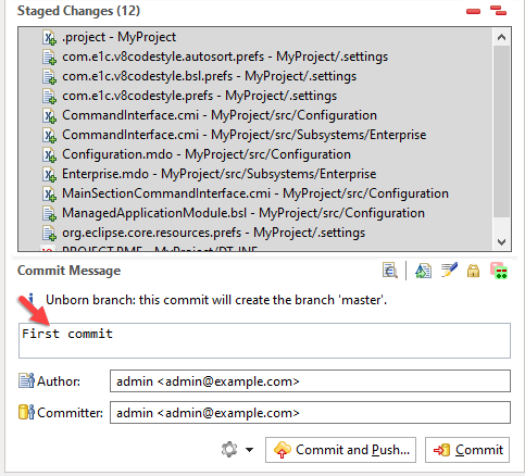
-
Click Commit.
-
-
As a result: All fields in the Git Staging panel will be cleared. In the Navigator panel, the angle bracket (>) will disappear before the project name. This bracket indicated that the state of the project files in the working tree differed from what was stored in the repository, since the repository previously contained nothing.
Sign Up on GitHub
Now, you will create an account on GitHub. The diagram represents it as follows:
-
Open github.com in your browser.
-
Click Sign up in the upper right corner.

-
Enter your email address and click Continue.
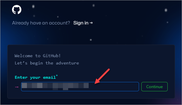
-
Enter your desired password and click Continue.
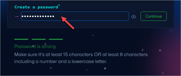
-
Enter your desired username and click Continue.
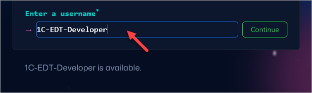
-
Optionally, check the box to receive product announcements and updates. Click Continue.
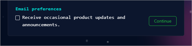
-
GitHub will ask you to complete a verification task. Click Verify.
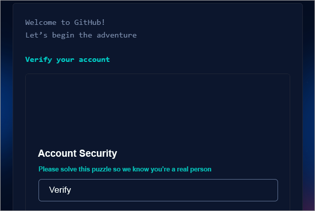
-
Arrange the item as instructed and click Submit.
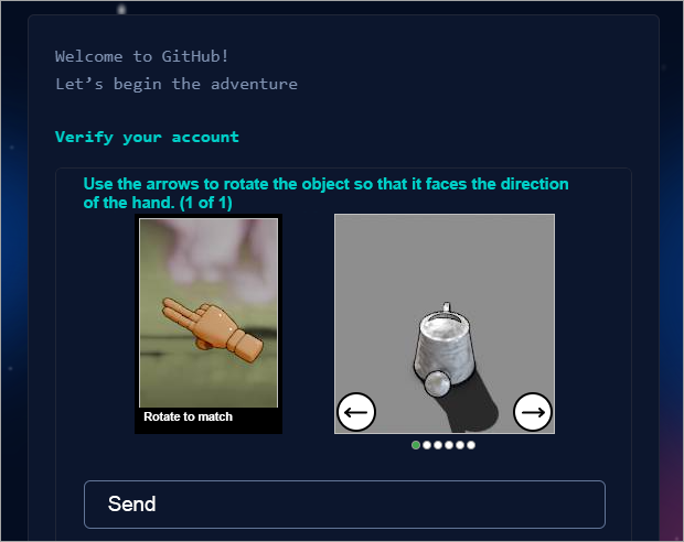
-
Enter the verification code sent to your email.
-
Sign into your account by entering your username and password, then click Sign in.

-
Indicate that you will be the only one working with the repository by selecting Just me and click Continue.

-
Skip tool selection and simply click Continue.

-
Click Continue for free to select the free plan.

-
You will then be redirected to your GitHub account's main page.
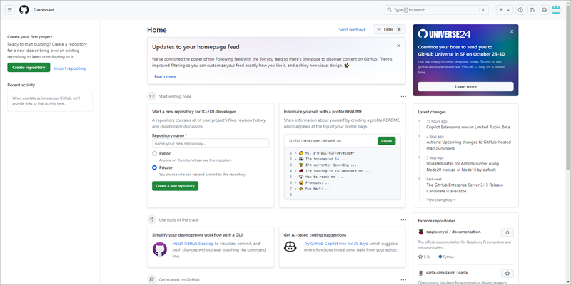
Create a Remote Repository on GitHub
Now, you will create an empty remote repository on GitHub. The diagram represents it as follows:
-
On the GitHub main page, fill in the basic repository properties:
-
In the Repository name field, enter the name of the repository.
-
Check the Public option so that everyone can view your repository.
-
Click Create a new repository.
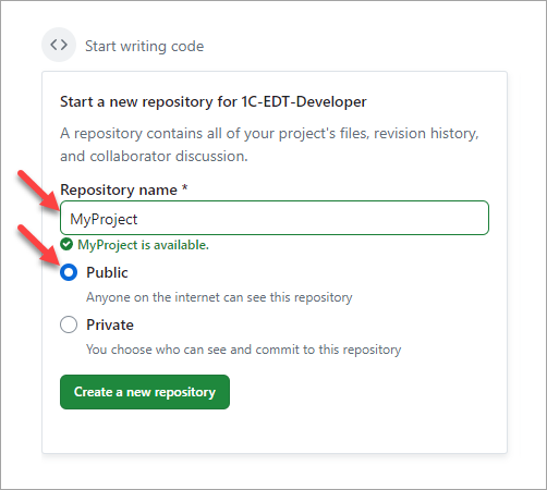
-
-
GitHub will create the repository and open its main page.
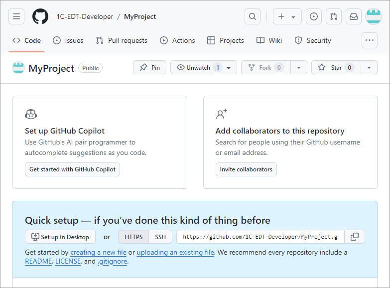
Obtain an Access Token
Now, you will obtain an access token on GitHub. An access token acts as a password, but it is intended for programs rather than users. 1C:EDT will use this token to authenticate on GitHub when you push project changes.
-
On the GitHub main page, open the profile menu by clicking the icon in the upper right corner.
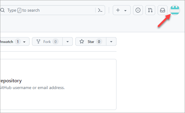
-
Click Settings at the bottom of the menu.
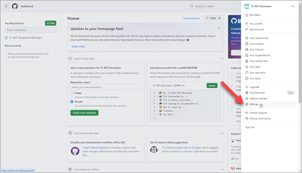
-
Scroll down and click Developer settings in the left menu.
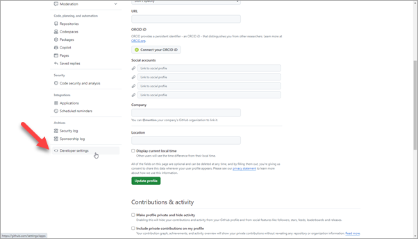
-
Expand the Personal access tokens section and click Token (classic).
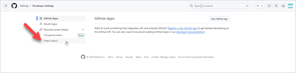
-
Open the Generate new token menu and select Generate new token (classic).
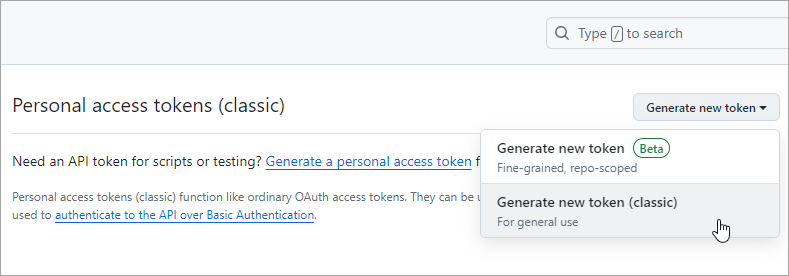
-
GitHub may ask you to re-authenticate. Enter your password and click Confirm.
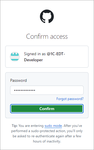
-
Fill in the token parameters:
-
Note is the name for the token to help you distinguish it from others.
-
Expiration specifies how long the token remains valid. For learning purposes, you can select No expiration, but for real work, it is recommended to set an expiration date no longer than one year.
-
Select scopes allows you to define access permissions. Check all boxes to ensure access to all areas.
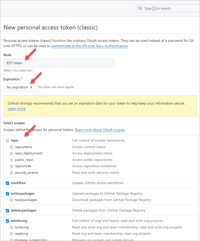
-
-
Scroll down and click Generate token.
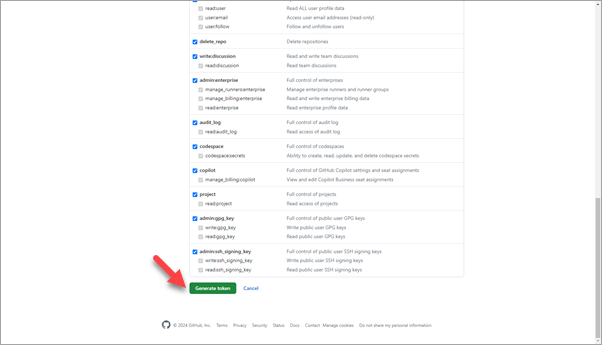
-
Copy the generated token and save it. You will need this token as a password when configuring push access to the remote repository.
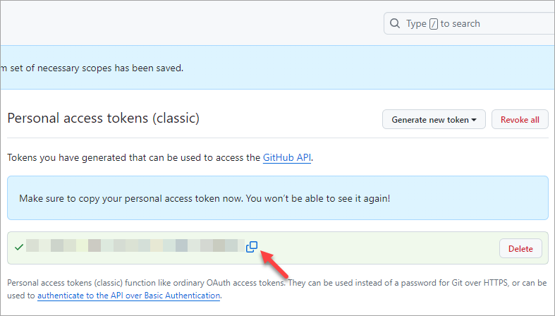
Push the Branch to the Remote Repository
Now, you will link your local repository to the remote repository on GitHub and push your changes for the first time. The diagram represents it as follows:
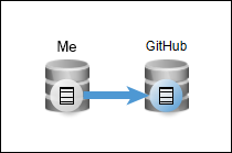
-
Open 1C:EDT or switch to it if it is already running.
-
Ensure that you are in the 1C:Enterprise perspective. The Git Staging panel should be open on the right. If the panel is missing, open it by clicking Window > Show View > Other… > Git > Git Staging.
-
In the lower part of this panel, click Push HEAD....
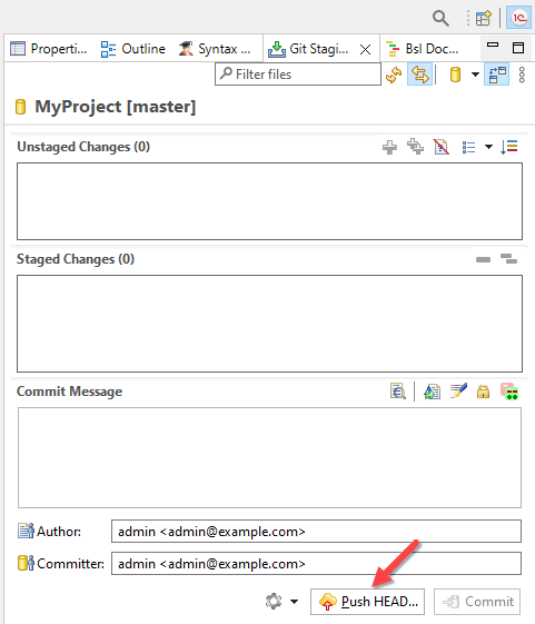
-
Here, you need to fill in the main properties of your remote repository on GitHub:
-
URI is the repository path, which needs to be copied from GitHub.
-
Username is your GitHub username.
-
Password is the access token you saved in the previous step.
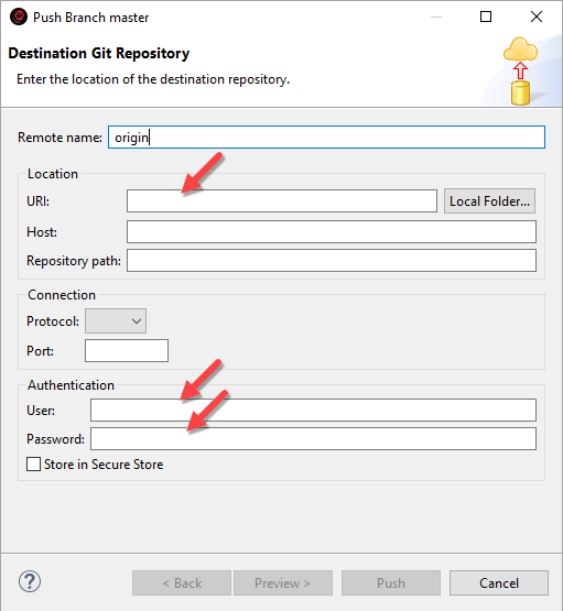
-
-
To find the GitHub repository path, open the browser tab where you obtained the token.
-
Click the menu icon in the upper-left corner, then select Home. You will be redirected to the homepage.
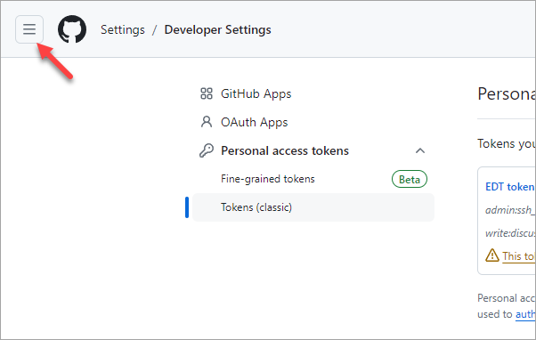
-
Your repositories are listed on the left. Click your repository.
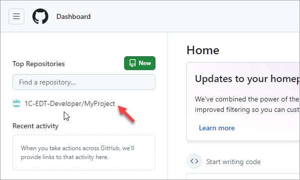
-
Make sure the HTTPS access protocol is selected, then copy the repository address.
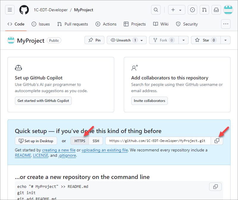
-
Return to 1C:EDT, fill in the remote repository properties, and check the Save in Secure Storage option. Click Next.
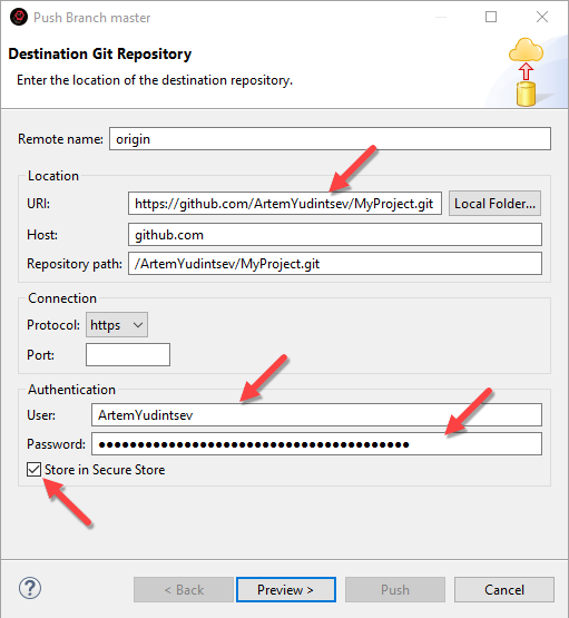
-
On the next screen, no changes are needed. The default remote repository settings are suitable. Click Next.
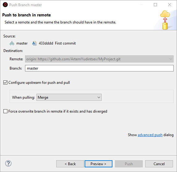
-
1C:EDT will ask you to confirm the push operation. Your master branch will be pushed to the remote repository MyProject in its master branch. The default checkbox selections are fine, so no changes are needed. Simply click Push.
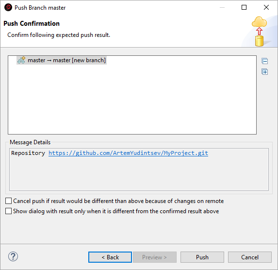
-
You can monitor the push progress in the lower-right corner of the screen.
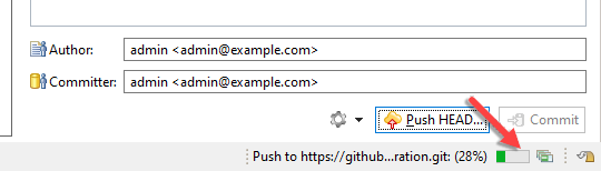
-
After a short time, 1C:EDT will display the push result.
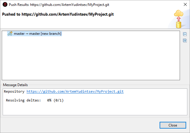
-
Everything is set up correctly, and a new branch master has been created in the remote repository. Click Close.
At this point, the connection to the remote repository is configured, and the first changes have been pushed.
View Change History and Push Changes to the Remote Repository
Now, you will review the change history stored in both the local and remote repositories. You will also see how to interact with these repositories.
-
To view changes in the local and remote repositories, you will need the History panel. In the Navigator panel, right-click the project and select Version Control (Team) > Show History from the context menu.
-
The panel will open in popup mode in the upper right corner of the screen, along with the Configuration Errors panel. To keep it visible at all times, expand this panel group. Click the
 (Restore) icon to pin the panel group at the bottom of the screen.
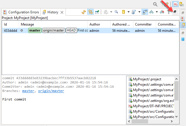
-
Currently, the History panel contains only a single commit. It is located in the local repository in the master branch, as indicated by the green icon. 1C:EDT uses green to mark local branches.
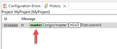
-
Additionally, the same commit is present in the remote repository’s master branch. This is indicated by the gray icon. 1C:EDT uses gray to mark remote tracking branches. “origin” is the default name for the remote repository, assigned during push configuration (see step 9).
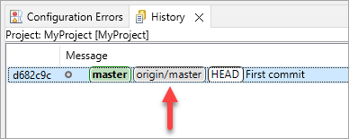
-
To make it easier to track changes, switch the History panel to display all repository changes. Expand the filter in its command bar and select All repository changes.
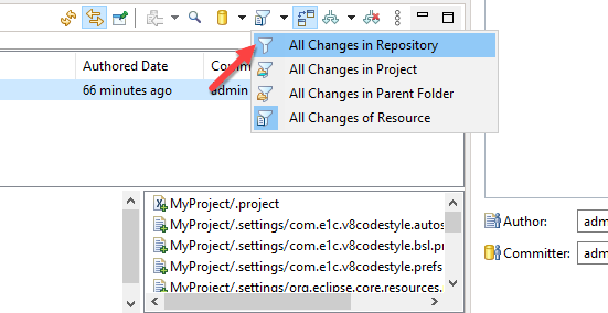
-
Now, you will create a few test commits, which you can later revert if needed.
-
Make some modifications to the configuration (e.g., add a catalog) and commit them to the local repository. Check how the history changes. To do this:
-
In the Navigator panel, right-click the Catalogs branch and select Create > Catalog > Done.
-
Add all files to the index.
-
Enter a commit message.
-
Click Commit (see Commit Configuration Changes).
-
-
You can see in the History panel that the history of your local repository has now diverged from the history of the remote repository. You have two commits, with the latest one labeled "Second commit". This is indicated by your local branch. Meanwhile, the remote repository still contains only the first commit.
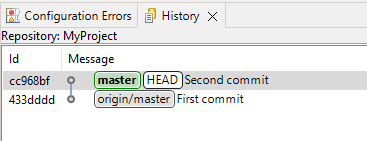
-
Make another change, for example, by adding a constant in the same way (Create > Constant > Done). Commit this change to the local repository.
-
Now you can see that the history has diverged further, with two commits present in your local repository that are not yet in the remote repository.
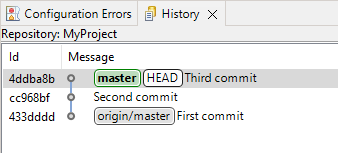
This information is also displayed in the Navigator panel in the project title. An upward arrow indicates that there are commits that have not yet been pushed to the remote repository. Currently, there are two such commits.
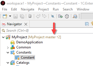
-
Now, suppose you make another change to the project, completing your task. The results need to be pushed to the remote repository so that other developers can use them.
To do this, add a document (Create > Document > Done), then click a different button, Commit and Push....
-
After a short while, you will see that once the changes were committed to the local repository, 1C:EDT pushed them to the remote repository and displayed the push result. Three commits that were missing in the remote repository have been pushed to the master branch.
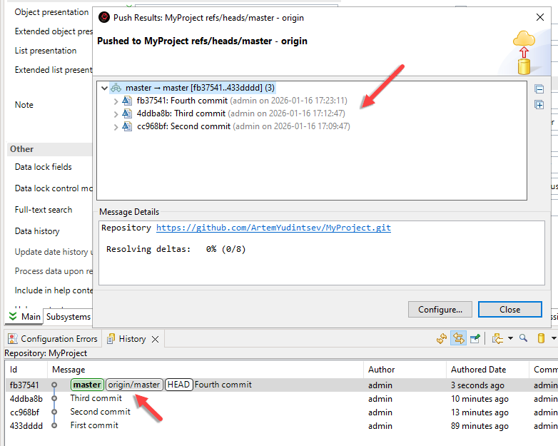
As a result, the local and remote repository histories are now synchronized. This is visible in the History panel, where branch pointers indicate the same latest commit.
Additionally, if you check the project title in the Navigator panel, you will see that the icons indicating unpushed commits have disappeared.
Reverting Commits
The second, third, and fourth commits created in the previous section were test commits. Now, you will revert them, restoring the repository history to its initial state, where only the first commit exists.
-
In the History panel, select the first commit.
-
Right-click it and choose Reset > Hard (HEAD, Index, and working tree) from the context menu.
-
1C:EDT will ask for confirmation. Click Reset.
-
After this, only the first commit will remain in the local repository, and the master branch will point to it.
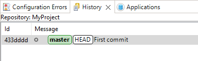
-
However, in the Navigator panel, you will notice that the remote repository still contains three commits that have not been fetched into the local repository. These are the commits you just reset: the second, third, and fourth commits.
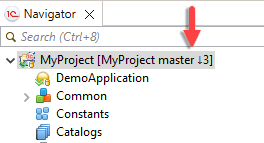
-
To align the remote repository history with the local one, push the changes to the remote repository. In the Git Staging panel, click Push HEAD....
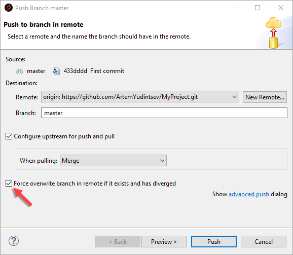
-
Select the Force Overwrite Remote Branch If It Exists and Has Diverged checkbox, and click Push.
DANGER
Use this option with caution! Git typically does not allow updating a remote branch that is not an ancestor of the local branch, as is the case here. This safeguard prevents losing commits in the remote repository that are missing in your local branch (for example, if other developers have pushed changes).
Enabling this option removes this protection and allows you to overwrite the remote branch with your local branch's state. This should only be done when you are certain that overwriting the remote branch will not cause issues for yourself or other developers.
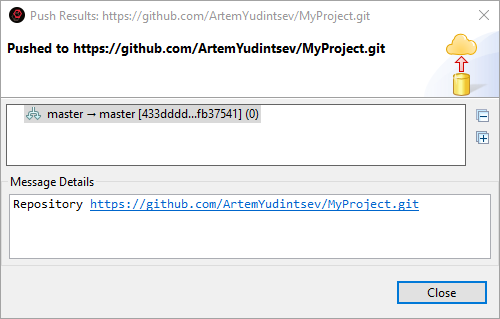
-
1C:EDT will confirm a successful push. If you check the project title in the Navigator panel, you will see that the icons indicating unpulled commits have disappeared.
Cloning a Remote Repository for Collaboration
This example demonstrates how to connect to a public GitHub repository and clone it to participate in development.
Tip: It is assumed that you have created and launched a new 1C:EDT Start project.
-
Sign up on GitHub.
-
Obtain an access token.
-
In the Navigator panel, click Import Project(s) from Git Repository.
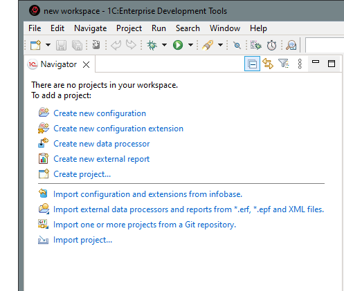
If the panel is already occupied with projects, click Import... > Git > Projects from Git in the context menu.
-
Select
 Clone URI and click Next.
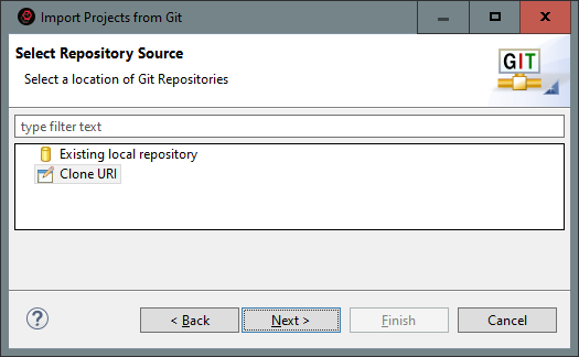
-
Fill in the details for the remote repository you are going to clone:
-
URI is the repository address, for example, https://github.com/1C-EDT-Developer/TeamProject.
-
Username is your GitHub username.
-
Password is your access token. Tip: If the repository is hosted on GitHub, you can find its URI as follows. In the repository's main page, click Code. You will see links for cloning using HTTPS, SSH, and other protocols.
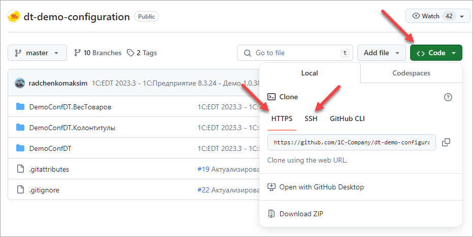
Check the box Save in Secure Storage and click Next.
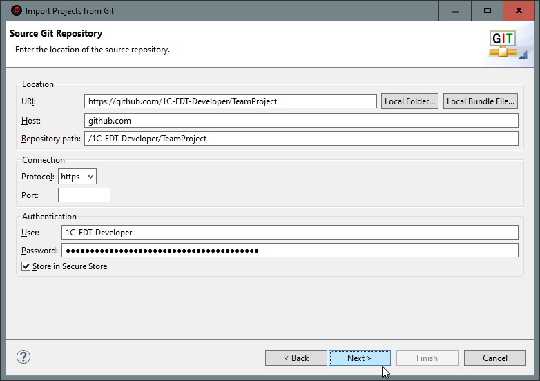
-
-
1C:EDT will connect to the remote repository and display the available branches. If certain branches are unnecessary, uncheck them. Click Next.
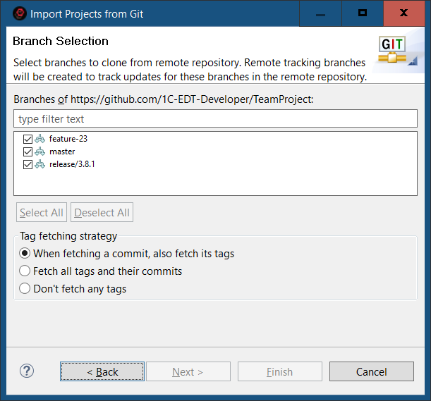
-
In the Directory field, enter the path to the directory where your local repository will be stored and click Next.
Warning: When creating a local repository, set it up so that the repository directory and the 1C:EDT workspace are not nested within each other. To learn more, read here.
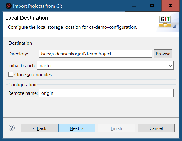
-
Fetching files from the remote repository will take some time. A progress indicator at the bottom of the window will display the process.
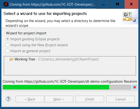
-
Once the file import is complete, the wizard will offer several options for creating a project. Ensure that Import from an existing Eclipse project is selected and click Next.
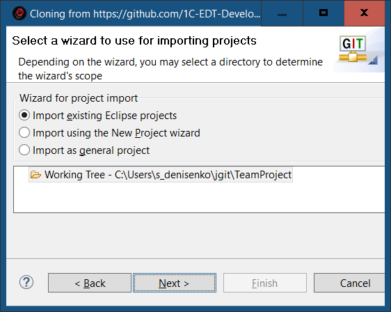
-
The contents of the cloned repository will be displayed. In this example, there is one project, which is already selected. Click Finish.
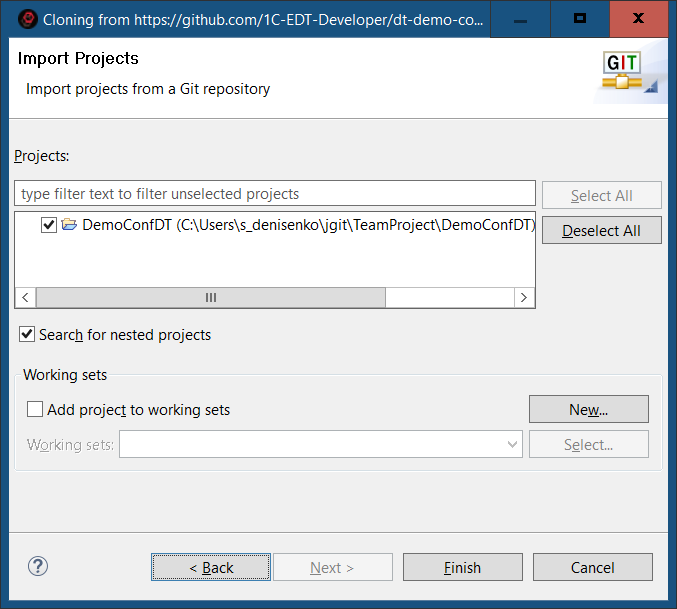
-
You can track the process in the bottom-right corner of the screen.
-
Once complete, the cloned project will appear in the Navigator panel.
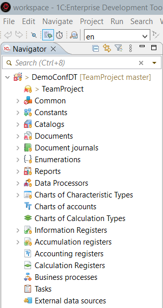
-
Switch to the Git perspective by clicking
> Git > Open in the Perspective panel.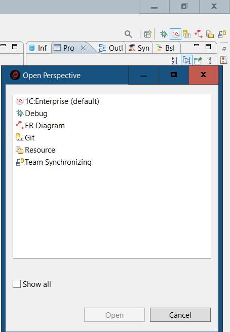
The Git Repositories panel will now display your local repository. Expand the Branches node. 1C:EDT has created three remote tracking branches and checked out the main master branch into the working tree, making it the current branch.
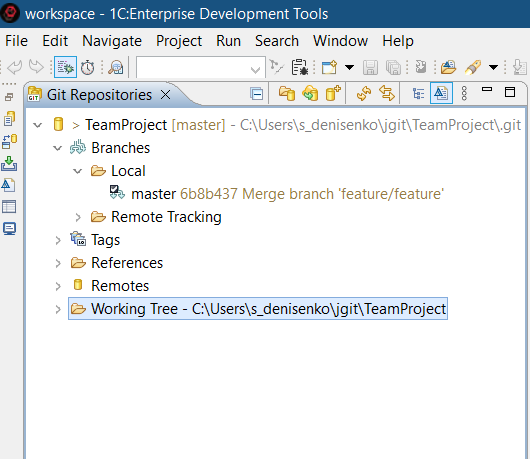
You can continue working in the master branch, create a new branch, or switch to any remote tracking branch, create a local branch from it, and work there.
Importing a Project from the 1C Repository
This example demonstrates how to connect to the public 1C Repository on GitHub and retrieve a project containing the demo configuration Managed Application. The repository address is https://github.com/1C-Company/dt-demo-configuration.
This example uses 1C:EDT 2024.1.1 and 1C:Enterprise 8.3.25.1394.
Tip: It is assumed that you have created and launched a new 1C:EDT Start project.
-
In the Navigator panel, click Import Project(s) from Git Repository.
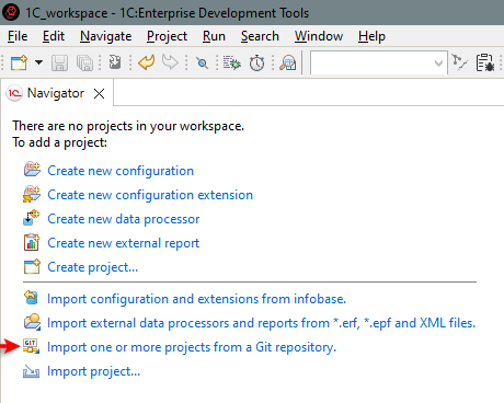
If the panel is already occupied with projects, click Import... > Git > Projects from Git in the context menu.
-
Select
Clone URI and click Next.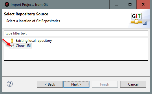
-
In the URI field, enter the 1C Repository address: https://github.com/1C-Company/dt-demo-conf iguration and click Next.
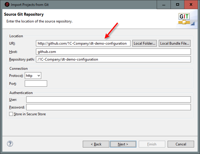
-
1C:EDT will connect to the remote repository and display the available branches.
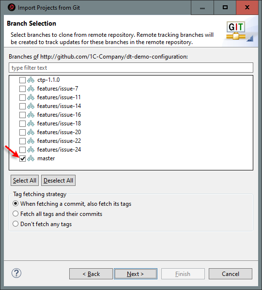
-
Click Deselect All, select the master branch, and click Next.
-
In the Directory field, enter the path to the directory where your local repository will be stored and click Next.
Warning: When creating a local repository, set it up so that the repository directory and the 1C:EDT workspace are not nested within each other. To learn more, read here.
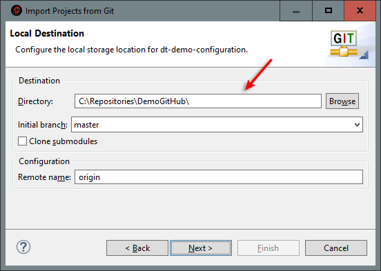
-
Fetching files from the remote repository will take some time. A progress indicator at the bottom of the window will display the process.
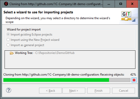
-
Once the file import is complete, the wizard will offer several options for creating a project. Ensure that Import from an existing Eclipse project is selected and click Next.
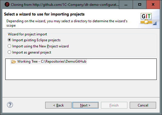
-
The contents of the cloned repository will be displayed. It contains three projects: the demo configuration and two of its extensions: Weight of Goods and Headers and Footers. All of them are selected by default. Click Finish.
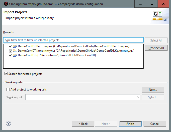
-
As a result, the Navigator panel will display the trees of three new projects: the configuration project (DemoConfDT) and its associated configuration extension projects (DemoConfDT.WeightOfGoods and DemoConfDT.Headers) (possible issue).
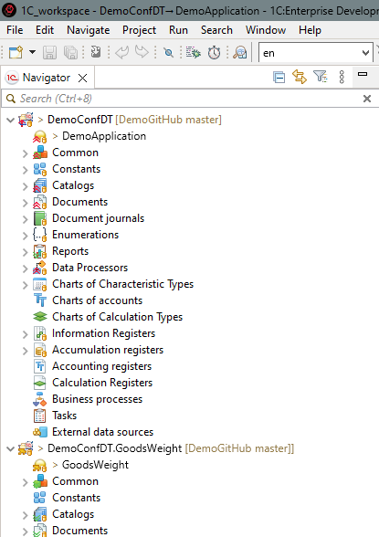
Forking a Repository on GitHub
Public repositories on GitHub typically do not allow direct modifications. You can clone such a repository and modify it locally, but you will not be able to push changes back to the server.
To enable external developers to contribute to public projects, GitHub provides a forking mechanism. A fork is created on GitHub but within your own workspace. You can clone your fork and work with it as a remote repository. Since this is your workspace, you have full rights to this copy. When you, as an external developer, complete your project, you can submit a pull request to the origin repository to request that changes from your fork be merged.
For some demonstration examples, you will need a remote repository. As such a repository, you will use a fork of one of the demonstration repositories provided by 1C.
Start with the preparation steps
-
Sign up on GitHub.
-
Obtain an access token. A token is not required to create a fork. However, you will need it when cloning the repository in order to push changes to your copy.
Complete the Task
-
On the repository’s main page, click Fork.
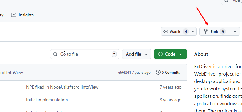
-
In most cases, the default settings suggested by GitHub are sufficient, so you can click Create Fork. If you prefer, you can first change the repository name, add a description, or uncheck the box to copy all branches instead of just the master branch.
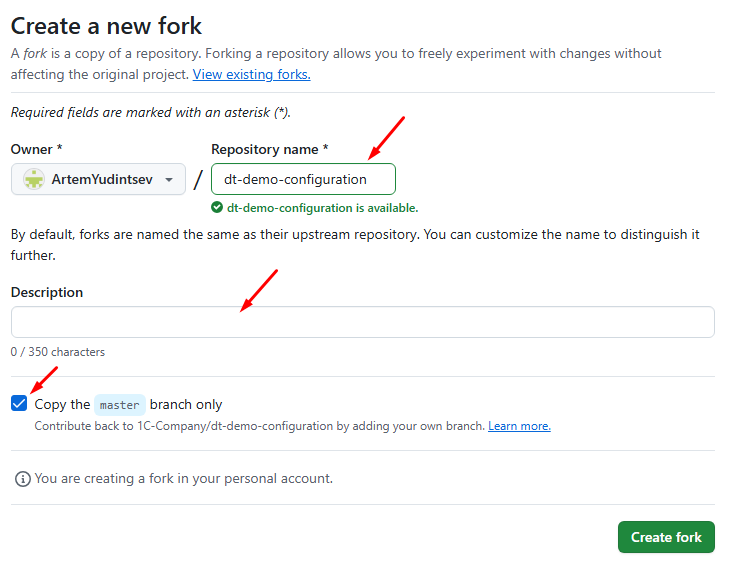
-
Once the fork is created, you will be redirected to the main page of the repository. To get the URI for cloning your fork, click Code. You will see links for HTTPS, SSH, and other protocols.
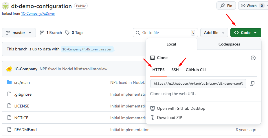
Fixing an Error in the Main Branch of the Remote Repository
Typically, errors are fixed in dedicated branches where corrections are made, tested, and merged into the main branch if everything is working correctly. However, minor corrections, such as typos in the interface that do not affect functionality, are often made directly in the main branch without additional testing.
In this example, you will simulate the activity of two developers interacting with a remote repository. Each will fix a small error directly in the main branch and push the changes to the server.
This example uses 1C:EDT 2024.1.1 and 1C:Enterprise 8.3.25.1394.
Start with the preparation steps
-
Sign up on GitHub.
-
Obtain an access token.
-
Create a fork of the repository https://github.com/1C-Company/dt-demo-configuration.
-
Launch 1C:EDT Start.
-
Create two new projects: ProjectMichael and ProjectJames.
For each of these projects:
- Launch the project.
- Click Get Started.
- Import the project from your fork. When importing, use the token instead of a password, otherwise, you will not be able to push changes to the GitHub repository. An error may occur.
Configure Git settings to track which developer made changes
- Click Window > Preferences... in the main menu.
- Go to Version Control (Team) > Git > Configuration.
- Open the Repository Settings tab.
- Add two entries using Add Entry:
- For ProjectMichael:
user.name = Michael
user.email = Michael@server.example.com-
- For ProjectJames:
user.name = James
user.email = James@server.example.com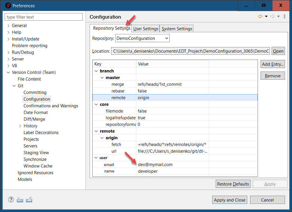
- Click Apply and Close.
Set Up the Workspace
- Open the History panel. To do this, in the Navigator panel, right-click the project and select Version Control (Team) > Show History from the context menu. The History panel will appear in the upper right corner.
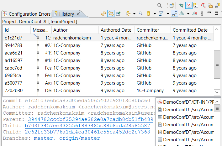
- Click the Restore icon. This will dock the History panel at the bottom of the screen.
- On the command bar, release the (Link with Editor) button so that the panel displays all commits, regardless of what is selected in the Navigator panel.
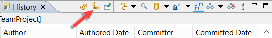
- Click
 (Change the File Scope for the History) and select the filter option All Repository Changes to display all commits in the panel.
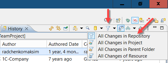
- Click
 (Change Which Commits to Show) and check
 refs/heads/**to view all local repository branches.
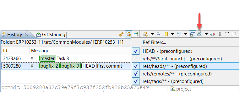
Complete the Task
-
Take a look around. Two developers, Michael and James, are working on an application. Both are connected to a remote repository, which in this case is your fork on GitHub. During this example, Michael and James will each fix a small issue directly in the main development branch, master. Since they will be making these changes concurrently, you will see how Git handles merging changes from different developers.
-
James is more experienced and is the first to fix an issue. The problem was that the project was missing constants:
-
Go to ProjectJames.
-
Add a constant to the DemoConfDT project.
-
Commit the changes:
-
In the Git Staging panel, enter the commit message: Commit 2.
-
Click Commit and Push... to commit the changes and immediately push them to the remote repository.
-
-
-
1C:EDT will display the result of the push. The commit was successfully pushed from the local master branch to the remote master branch.
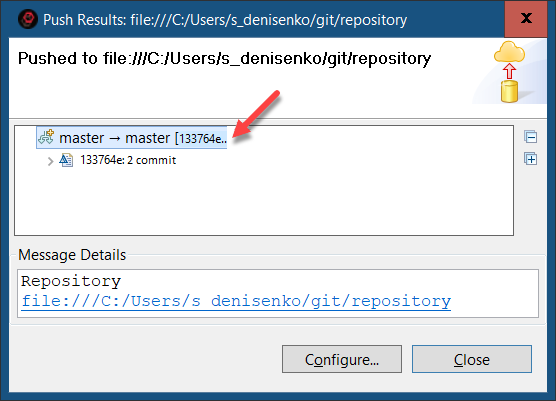
-
In the History panel, you can see that a new commit by James has appeared in the current local branch master. This commit has become the branch head, and the same commit is on the server, with the remote branch master (origin/master) pointing to it. At this point, the local repository history matches the remote repository history.
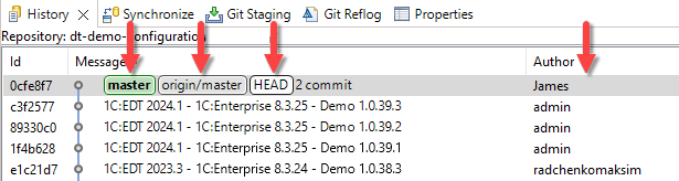
-
Now it is Michael’s turn. He also fixes an issue. The problem was that the project was missing catalogs:
-
1C:EDT will display the result of the push. This time, the push will be rejected. Pushing changes from the local master branch to the remote master branch is denied.
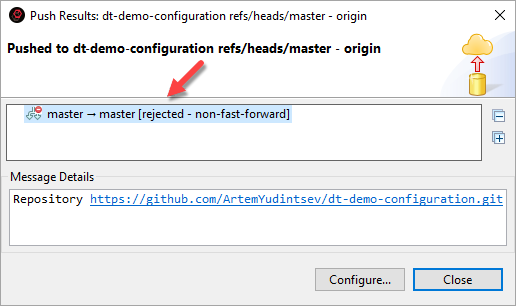
-
In the History panel, you can see that the local master branch now contains a new commit from Michael at its head. However, this commit was not pushed to the server, and the remote master branch remains unchanged. The pointer origin/master indicates this. This means the local repository history has diverged from the remote repository history. There is one unpushed commit.
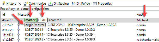
-
This situation requires some clarification:
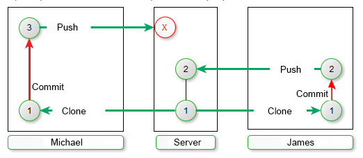
James fetched the latest changes from the server (Commit 1), made his own changes (Commit 2), and successfully pushed them because the state of the remote branch had not changed in the meantime.
Michael also fetched the latest changes from the server (Commit 1) and created his own changes (Commit 3). However, by this time, James’s changes (Commit 2) had already been pushed to the remote repository. For Michael’s changes (Commit 3) to appear on the server, they need to be merged with James’s changes (Commit 2). Git does not perform such operations on the server, which is why Michael’s push was rejected. Even though Michael and James modified different parts of the project,
Git requires conflicts to be resolved locally. To resolve this, Michael must first fetch James’s changes (Commit 2) from the server, merge them with his own changes (Commit 3), and only then push the result to the remote repository. This process will look as follows in the diagram:
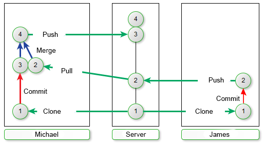
-
Fetch the changes from the server and merge them into your local branch. To do this, in the Navigator panel, right-click the project and select Version Control (Team) > Pull from the context menu.
-
1C:EDT displays the result of fetching and merging the changes. The server, from the remote branch origin/master, retrieved James’s commit (Commit 2) and successfully merged it with Michael’s commit (Commit 3). As a result, a merge commit is created.
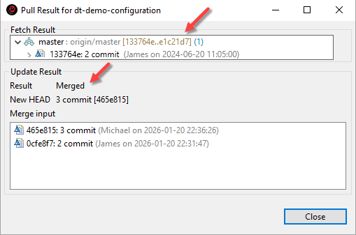
-
In the History panel, you can see that 1C:EDT received James’s commit (Commit 2) from the server and marked the tracking branch (origin/master) to indicate that the master branch in the remote repository now points to this commit. 1C:EDT then merged this commit into the local branch and created a new commit. The merge commit became the head of the local master branch.
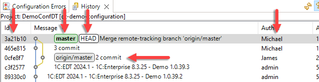
-
Now, the local master branch can be pushed to the server. In the Navigator panel, right-click the project and select Version Control (Team) > Push to origin from the context menu.
-
1C:EDT will display the result of the push. Two commits were successfully pushed from the local master branch to the remote master branch: Michael's third commit and the merge commit created as a result of integrating James' changes.
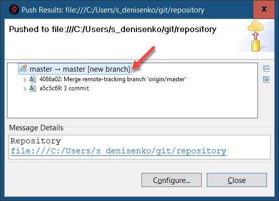
-
In the History panel, you can see that the remote branch master now points to the same commit as the local branch. This confirms that all commits have been pushed to the server and that the local repository history now matches the remote repository history.
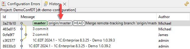
-
Take another look at the overall workflow:
James made changes to the master branch and pushed them to the server. Michael also made changes to the master branch. However, since James’s changes had already been pushed to the server, Michael needed to fetch those changes, merge them with his own (Version Control (Team) > Pull), and then push them to the server.
Creating a Project in a Feature Branch and Merging It into the Main Branch of the Remote Repository
New functionality is usually developed in feature branches. This approach keeps the main development branch in a stable state, ready for release. In a feature branch, you can modify the application freely, test enhancements, and once everything is verified, merge the changes into the main branch.
In this example, you will simulate the activity of two developers interacting with a remote repository. One of them fixes a minor issue directly in the main branch, while the other works on a feature branch and later merges their changes into the main branch on the server.
This example uses 1C:EDT 2024.1.1 and 1C:Enterprise 8.3.25.1394.
Start with the preparation steps
-
Sign up on GitHub.
-
Obtain an access token.
-
Create a fork of the repository https://github.com/1C-Company/dt-demo-configuration.
-
Launch 1C:EDT Start.
-
Create two new projects: ProjectMichael and ProjectJames.
For each of these projects:
- Launch the project.
- Click Get Started.
- Import the project from your fork. When importing, use the token instead of a password, otherwise, you will not be able to push changes to the GitHub repository. An error may occur.
Configure Git settings to track which developer made changes
- Click Window > Preferences... in the main menu.
- Go to Version Control (Team) > Git > Configuration.
- Open the Repository Settings tab.
- Add two entries using Add Entry:
- For ProjectMichael:
user.name = Michael
user.email = Michael@server.example.com-
- For ProjectJames:
user.name = James
user.email = James@server.example.com
- Click Apply and Close.
Set Up the Workspace
- Open the History panel. To do this, in the Navigator panel, right-click the project and select Version Control (Team) > Show History from the context menu. The History panel will appear in the upper right corner.
- Click the Restore icon. This will dock the History panel at the bottom of the screen.
- On the command bar, release the (Link with Editor) button so that the panel displays all commits, regardless of what is selected in the Navigator panel.
- Click (Change the File Scope for the History) and select the filter option All Repository Changes to display all commits in the panel.
- Click (Change Which Commits to Show) and check
refs/heads/**to view all local repository branches.
Simulate Michael’s Workflow
- Go to ProjectMichael.
- Add a constant to the DemoConfDT project.
- Commit the changes:
- In the Git Staging panel, enter the commit message: Commit 2.
- Click Commit and Push... to commit the changes and immediately push them to the remote repository.
- Close ProjectMichael and switch to ProjectJames.
Complete the Task
-
James's task is to create a feature branch feature, implement a small project in it by adding a catalog, a document, and an enumeration as an example, and then merge these changes into the main branch and push them to the server. If Michael had not made any changes, James's workflow would have followed this sequence.
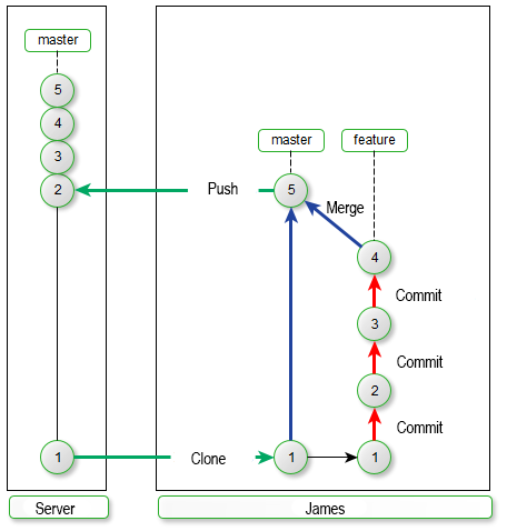
However, while James was planning his project, Michael fixed a minor issue directly in the main branch master. Now, the server contains Michael's changes, which James does not have.
In this example, you will see how James can transfer his changes to the main branch on the server.
-
Create a new branch from master and switch to it (possible issue). To do this:
-
In the Navigator panel, right-click the project and select Version Control (Team) Create New Branch... from the context menu.
-
Select:
-
Branch Type Feature
-
Branch Name feature
-
Development Infobase Create a new empty infobase
-
Click Finish.
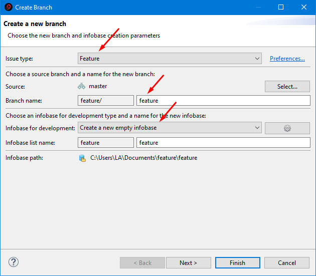
-
-
Once the new branch is created, 1C:EDT switches the project to it. This is indicated in the project title.
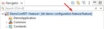
Additionally, 1C:EDT opens the Development panel, where you can see the new development branch and the new infobase.
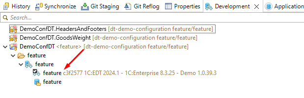
-
-
Create James's Small Project For this example, the project consists of three commits. First, add a catalog, then a document, and finally an enumeration.
-
Add a catalog to the DemoConfDT project.
-
Commit the changes:
-
In the Git Staging panel, enter the commit message: Third commit.
-
Click Commit to commit the changes to the local repository.
-
-
-
In the History panel, a new James's commit appears in the current local branch feature/feature, marking it as the head of the branch. The local branch master and its respective remote branch origin/master remain unchanged.
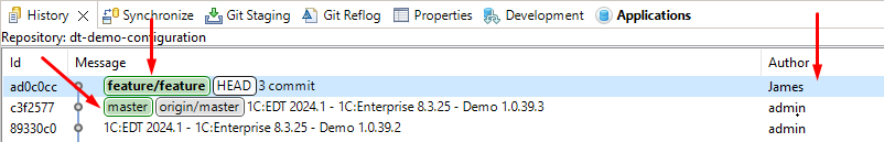
-
Similarly, add a document to the project with the commit message Fourth commit and an enumeration with the commit message Fifth commit. In the History panel, you will see the changes reflected.
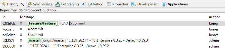
-
James's small project is now complete. He wants to merge it into the master branch and push it to the server.
-
First, switch to the local master branch. To do this, in the History panel, right-click Check Out the commit pointed to by the master branch. 1C:EDT asks which branch you want to check out since two branches point to this commit. Select the local branch master and click Checkout.
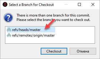
-
To merge James's project into the current master branch, right-click Merge the commit pointed to by the feature/feature branch.
-
1C:EDT displays the merge settings dialog. No changes are needed, click Merge.
-
1C:EDT shows the merge result, indicating that a fast-forward merge was executed.
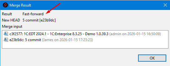
-
In the History panel, the pointer for the local branch master moves forward, and both local branches now match.
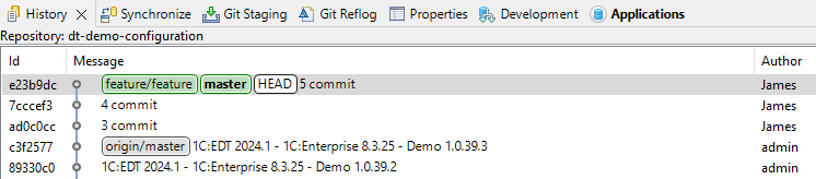
-
-
The final step is to push the master branch changes to the server. In the Navigator panel, right-click the project and select Version Control (Team) > Push to origin from the context menu.
-
1C:EDT will display the result of the push. The push operation is rejected. Pushing changes from the local master branch to the remote master branch is denied.
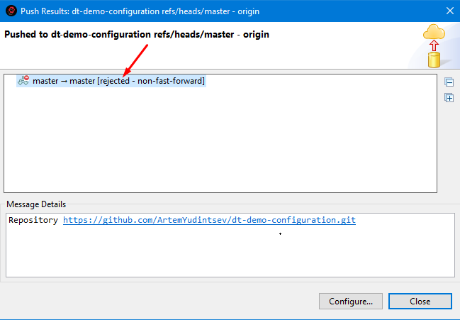
This is the expected result. As you may recall from a previous example Fixing an Error in the Main Branch of the Remote Repository, since another developer's changes have appeared on the server, you must first merge them locally before pushing your changes.
-
Fetch the changes from the server and merge them into your local master branch. To do this, in the Navigator panel, right-click the project and select Version Control (Team) > Pull from the context menu.
-
1C:EDT displays the result of fetching and merging the changes. From the remote branch origin/master, Michael's second commit is fetched and successfully merged with James's fifth commit. As a result, a merge commit is created.
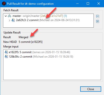
-
In the History panel, you can see that 1C:EDT retrieved Michael's commit (second commit) from the server and marked in the remote tracking branch (origin/master) that the master branch in the remote repository is now at that commit. 1C:EDT then merged this commit into the local branch and created a new commit. The merge commit became the head of the local master branch.
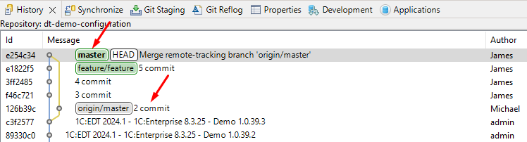
-
Now, the local master branch can be pushed to the server. In the Navigator panel, right-click the project and select Version Control (Team) > Push to origin from the context menu.
-
1C:EDT will display the result of the push. Two commits were successfully pushed from the local master branch to the remote master branch: three of James's commits and the merge commit that was created when merging Michael's changes.
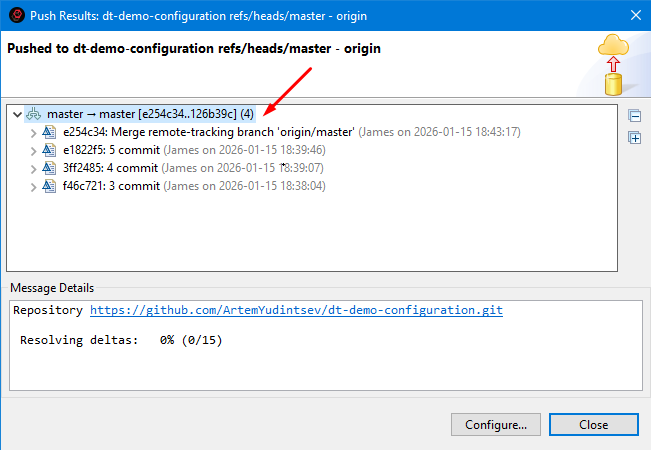
-
In the History panel, you can see that the remote branch master now points to the same commit as the local branch. This means all commits have been pushed to the server, and the local repository history now matches the remote repository history. The feature/feature branch can be deleted since all its changes are now in the main branch.
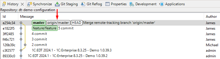
-
If you look at the workflow diagram, the completed task follows this sequence:
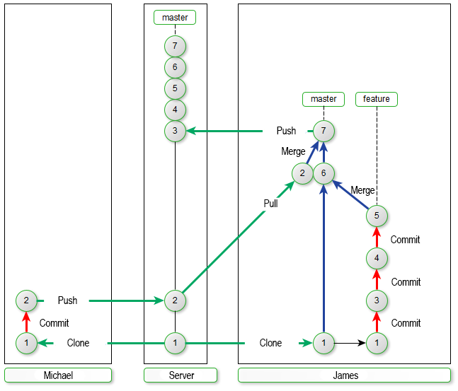
James merged the feature/feature branch into master, then fetched updates from the server into master, merged them, and pushed the result to the server.
-
The same result could have been achieved in a different order by first fetching changes from the server into master and then merging the feature/feature branch into it. The workflow diagram would look different, but in the History panel, the results would be the same.
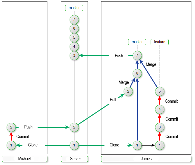
Resolving Conflicts When Merging Modules
Conflicts may arise when merging Git branches, requiring manual resolution.
A conflict occurs when the same application element is modified by two different developers or by the same developer in separate branches. In such cases, 1C:EDT may not always determine which changes should be applied.
The following example demonstrates conflicting changes that may occur in a module. You will merge these changes to ensure both developers' modifications are included. The merge commit will document how the conflict was resolved.
This example was created using 1C:EDT 2024.1.1 and 1C:Enterprise 8.3.25.1356.
Start with the preparation steps
-
Launch 1C:EDT Start.
-
Create a new 1C:EDT Start project.
-
Run this project.
-
Click Get Started.
-
Import all project branches from the repository https://github.com/1C-Company/team-demo-edt2 (an error may occur).
-
To make it easier to track results, prepare the workspace:
-
Open the application module Demo2.
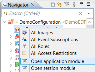
-
Open the History panel. To do this, in the Navigator panel, right-click the project and select Version Control (Team) > Show History from the context menu. The History panel will appear in the upper right corner.
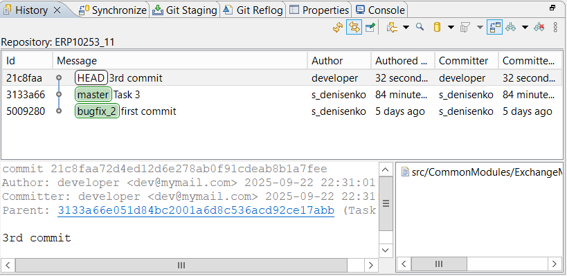
-
Click the Restore icon. This will dock the History panel at the bottom of the screen.
-
On the command bar, release the
(Link with Editor) button so that the panel displays all commits, regardless of what is selected in the Navigator panel. -
Click
(Change the File Scope for the History) and select the filter option All Repository Changes to display all commits in the panel.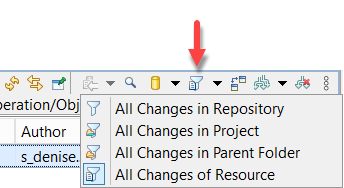
-
Click
(Change Which Commits to Show) and check refs/heads/** to view all local repository branches.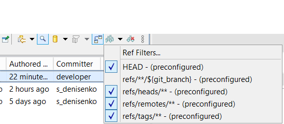
-
Retrieve the Local feature Branch This step is not strictly necessary because the master branch can incorporate the remote tracking branch origin/feature. However, retrieve the feature branch locally for clarity, so the example looks as if it is your branch being merged into master.
To do this, switch to the remote tracking branch origin/feature and select the option to create a new local branch.
-
Complete the Task
-
Take a look around. Two developers have made changes in different branches. You are playing the role of James, who has finished his work, created four commits, and is preparing to merge his changes into master.
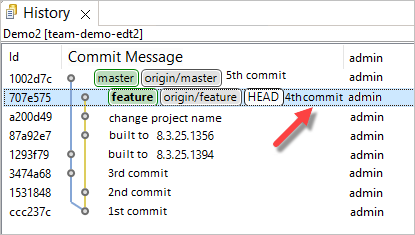
-
Switch to the master branch.
-
To merge the feature branch into the current master branch, in the Navigator panel, click Version Control (Team) > Merge... in the project's context menu. You will try two different methods for merging modules.
-
For the first attempt, select the local feature branch and do not change any standard settings. Click Merge.
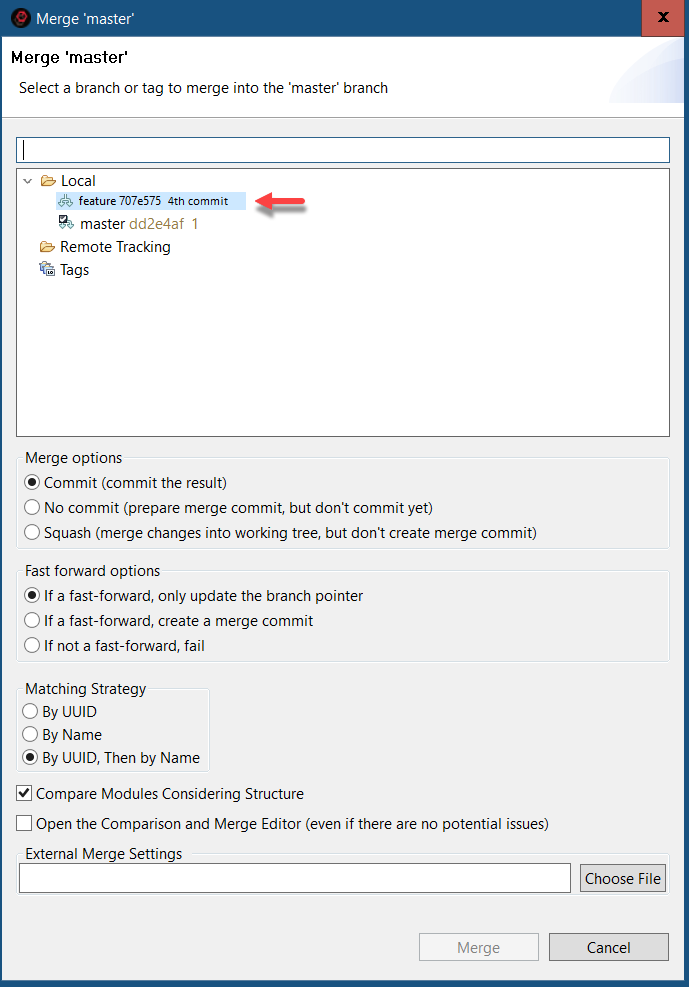
-
1C:EDT will open the Compare and Merge Configurations Editor. All hierarchy levels of objects will be collapsed. To expand them easily, place the cursor on the first line and then hold the right arrow key.
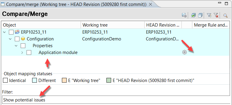
The editor provides several filters that allow you to view configuration differences. When merging Git branches, a three-way comparison runs: the common ancestor and the changes made in both branches relative to it. If these changes do not conflict, they are merged automatically. If the same application element has been modified in both branches, a conflict occurs, which must be resolved manually. When merging branches, 1C:EDT applies the Show Potential Issues filter, which highlights conflicts. You can see that there is a conflict in the application module.
-
To examine the conflict, click the gear icon next to Application Module. 1C:EDT will open the Compare and Merge Modules Editor.
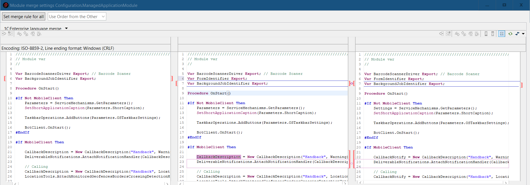
The left pane contains the module text from your current directory, which is from the master branch. The right pane contains the module text from the feature branch that is being merged into master. The center pane shows the merge result suggested by 1C:EDT.
To understand the changes made in the module, the next images will show its original text, which is found in the commit that serves as the common parent of both branches.
-
The first section in the module is the variable declaration area.
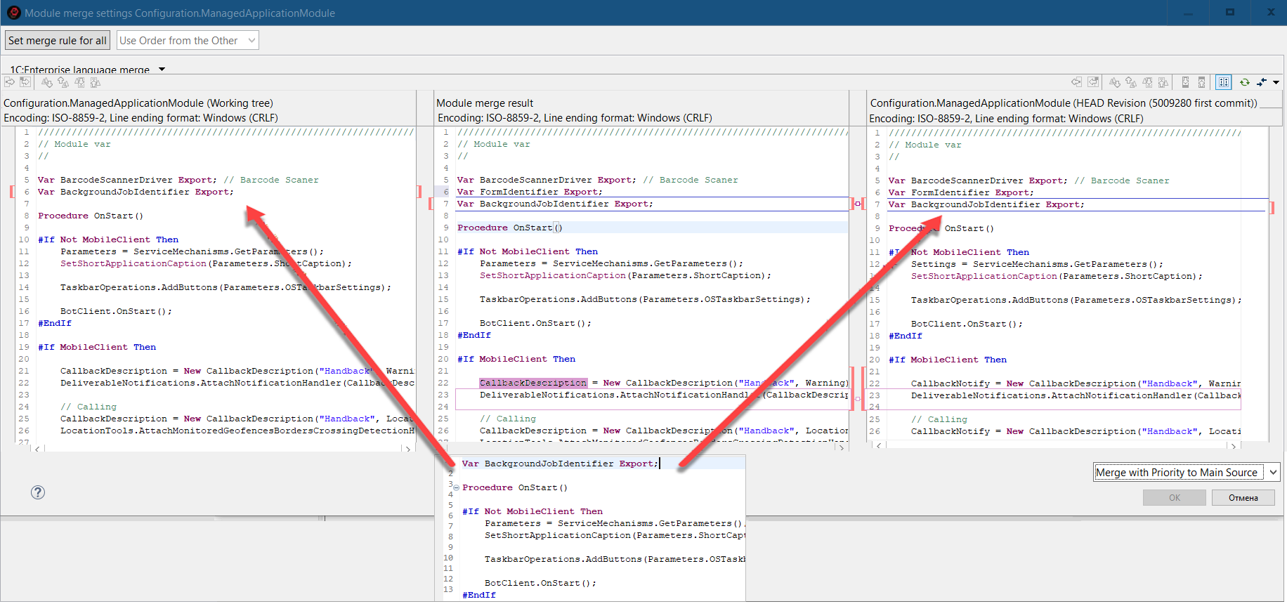
Each developer added a variable declaration here. 1C:EDT cannot decide which line to insert into the final result, so this section is marked as a conflict with red brackets.
-
The next three procedures do not have conflicts.
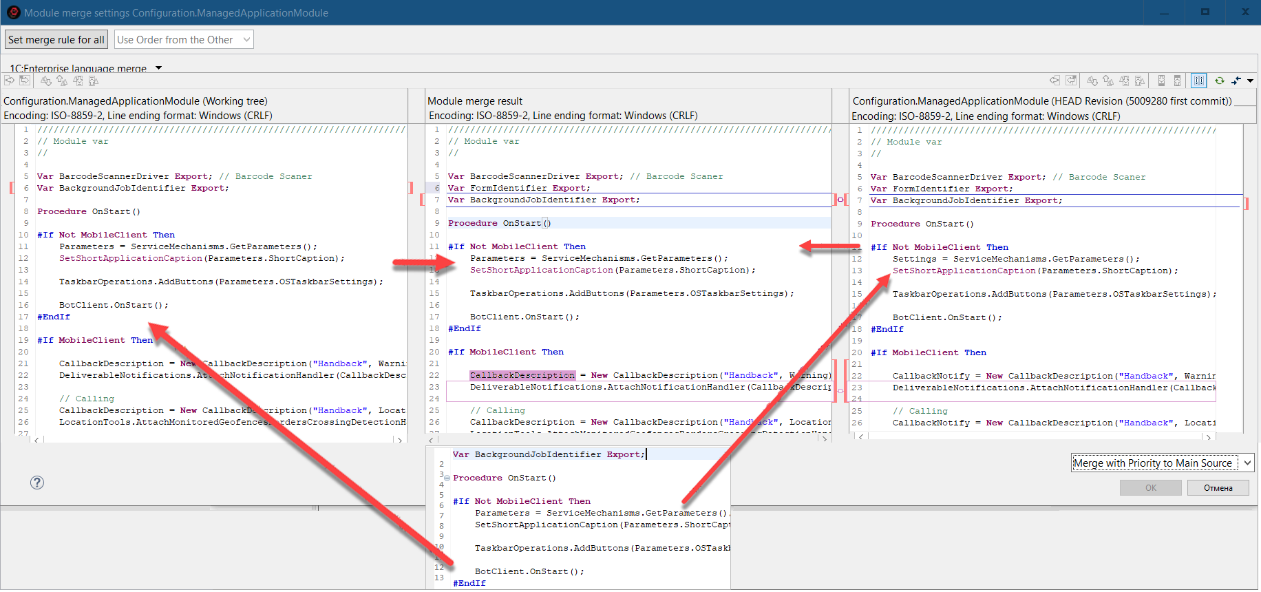
-
The BeforeStart() procedure was modified in the master branch, and 1C:EDT suggests using this version in the final result.
-
The OnGlobalSearch() procedure was changed only in the feature branch, and 1C:EDT recognizes this, incorporating the modified procedure into the final result.
-
The third procedure, OnStartup(), remains unchanged.
-
-
At the end of the module, each developer has added their own procedure.
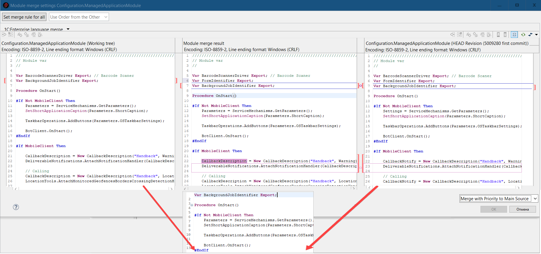
Even though the procedures have different names, 1C:EDT treats them as regular program text during a standard comparison and marks this area as a conflict with red brackets, just as it did at the beginning of the module.
-
Thus, the module contains two conflicts that require your resolution. However, this does not mean that 1C:EDT does not know how to handle conflicts. 1C:EDT provides two strategies for merging conflicting changes, with the default being merging with priority given to the main source. When merging the feature branch into the master branch, the main source is master. This means that in conflict areas, 1C:EDT suggests taking the changes from the master branch, which appears in the left pane.
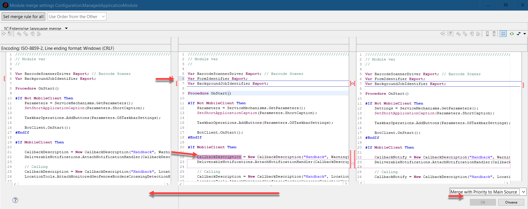
-
For the sake of interest, you can check how the second conflict resolution strategy works. To do this, switch the merge option to Merge with Priority to Other Source. The other source in this case is feature, so 1C:EDT will take the changes from the right pane.
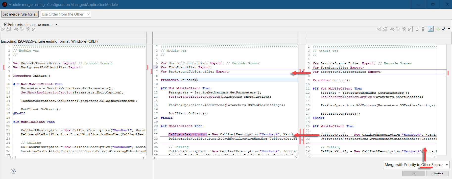
Revert to the previous merge strategy by selecting Merge with Priority to Main Source.
-
It is good that 1C:EDT has conflict resolution strategies, but in this case, both developers' changes should be included in the result: the variable declarations MainVariable and SecondVariable, as well as the procedures MainProcedure() and Second(). This can only be done manually by copying the necessary lines and pasting them into the central pane. However, you will not do this now and will instead try the second comparison method.
-
Close the Compare and Merge Modules Editor, and then close the Compare and Merge Configurations Editor. In the Navigator panel, click Version Control (Team) > Merge... again in the project's context menu. This time, also select the local feature branch and additionally select the Compare Modules Considering Structure checkbox. Click Merge.
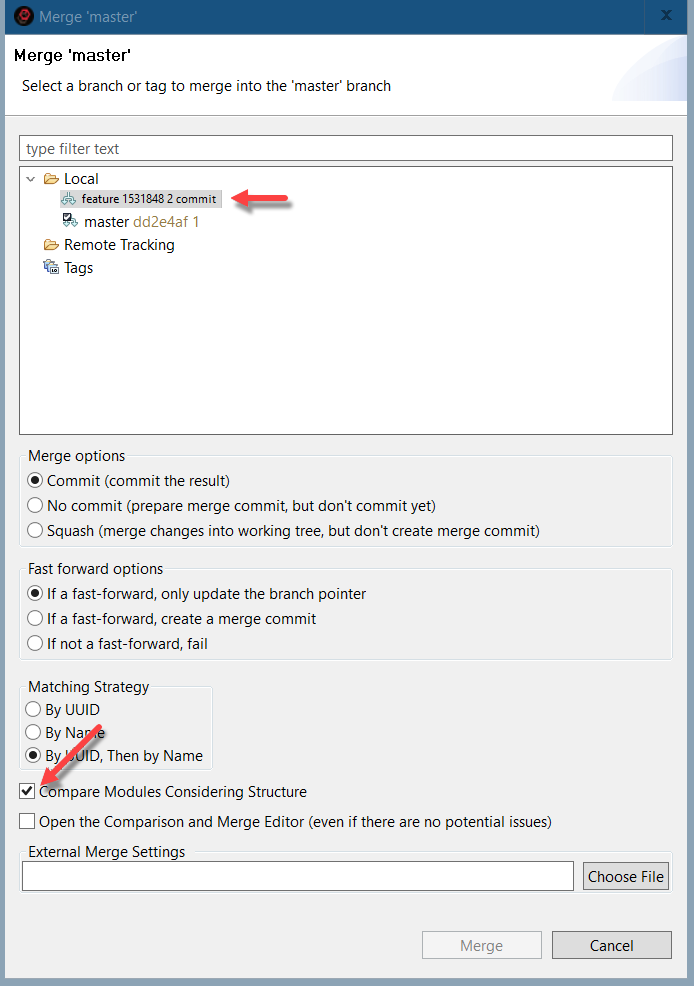
-
The Compare And Merge Configurations Editor will still show a conflict in the application module, but now an additional line will indicate that the conflict is in the variable definition section. No other conflicts remain, even though earlier there were two conflicts in the module. To understand what happened, switch the filter to three-way comparison.
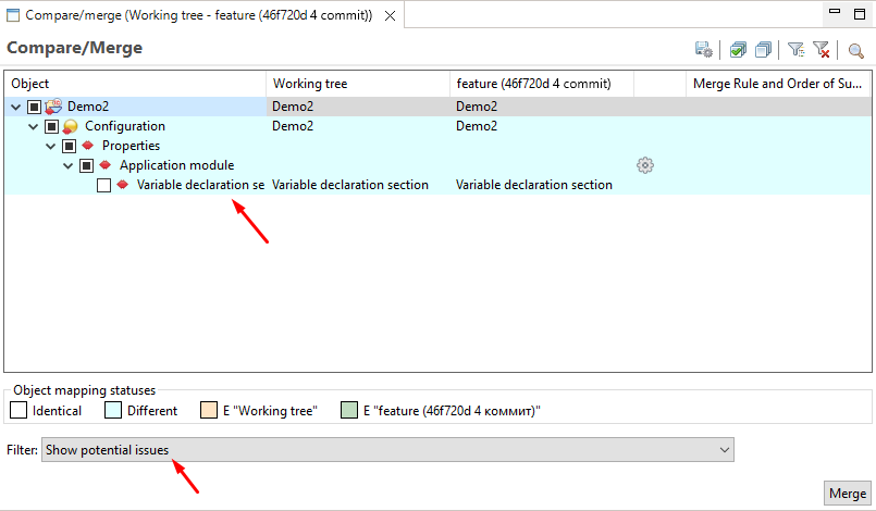
-
You will see that 1C:EDT has divided the module into individual procedures and handled each one individually:
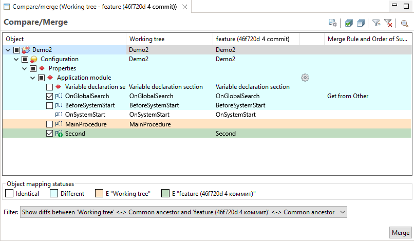
-
In the variable definition section, a conflict remains. There is no way around this.
-
The OnGlobalSearch() procedure was modified only in the feature branch, so it is marked for merging.
-
The BeforeStart() procedure was modified only in the master branch, so it is not marked for merging. The version from master will be used.
-
The OnStartup() procedure was not changed and does not participate in the merge.
-
The MainProcedure() was added only in the master branch, so it is not marked for merging. The version from master will be used.
-
The Second() procedure was added only in the feature branch, so it is marked for merging and will be taken from this branch.
-
-
Advantages of Comparing Modules with Structure Consideration
-
1C:EDT can more accurately assess changes in each branch and merge them without conflicts (for example, the MainProcedure() and Second() procedures).
-
You can use different merge strategies (take from the main source or from the other source) for individual procedures. When comparing without structure consideration, you can only select a merge strategy for the entire module.
-
In the module comparison and merge editor, each procedure can be compared separately, which can be more convenient since other module text does not distract you. Disadvantages of Comparing Modules with Structure Consideration
-
Additional time is required for 1C:EDT to analyze the module content and construct its structure before performing the comparison.
-
Due to certain issues (syntax errors, incorrect use of preprocessor directives), 1C:EDT may not always be able to analyze the module's content, in which case it will fall back to comparison without structure consideration. For these reasons, the Compare Modules Considering Structure checkbox is disabled by default.
-
-
To resolve the conflict in the variable declaration section, click the gear icon in the Application Module row. The familiar Compare and Merge Modules Editor will open, but now each procedure has its own row. Select the row Variable Declaration Section.
As you already know, to include both developers' changes in the result, you need to copy them manually into the central pane. The changes from the master branch are already there.
Copy the line
Var SecondVariable Export.from the right pane to the central pane. Click OK.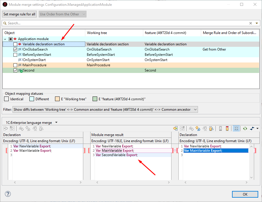
-
In the Compare and Merge Configurations Editor, you will see a mark on the gear icon indicating that the comparison mode has been manually set in one of the procedures, and the Variable Declaration Section line will display the Manual Merge mode. Click Merge.
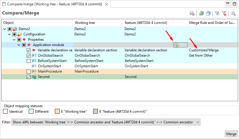
-
The merge will be completed, and you will see the updated application module text. It now includes changes from both developers. As you understand, in the first comparison mode, without structure consideration, you could have manually transferred both variable definitions and both procedures to the result in the same way.
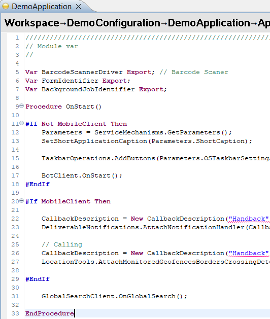
-
1C:EDT has automatically created a merge commit and titled it Merge branch 'feature'. This is fine, but according to the example's conditions, you must specify in this commit how the merge conflicts were resolved. This ensures that other developers can correctly understand the change history.
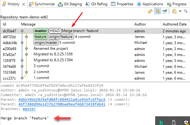
-
To update the message, edit the last commit. As long as this is your local commit and you have not pushed it anywhere, this can be done without any issues. In the commit message, add a new line and write "Merged changes from both developers."
-
As a result, the last commit will be replaced with a new one that is identical but includes your message.
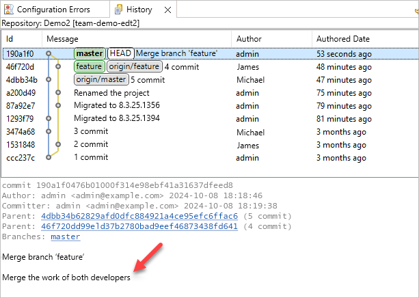
Hiding Language Errors of the Main Branch
Applied solutions may contain a large number of errors that do not prevent the application from functioning but indicate that certain development standards were not followed. With many other errors present, it can be difficult to notice an error introduced during the current development process.
When a team develops an application using Git, a new branch is usually created to implement a new feature or fix an issue. This branch diverges from the main branch, such as master. 1C:EDT allows hiding all language errors that previously existed in the main branch while working in the current branch. As a result, only errors introduced in the current branch are visible.
Note that this does not hide all project errors but only those related to the use of the 1C:Enterprise language. Errors related to configuration properties or individual objects remain visible. For example, when editing modules, "old" errors will not be displayed, but the Configuration Errors panel will still show all old errors related to the configuration rather than the modules.
This example was created using 1C:EDT 2024.1.1 and 1C:Enterprise 8.3.25.1356.
Start with the preparation steps
Complete the Task
-
Import all project branches from the repository https://github.com/1C-Company/team-demo-edt3 (an error may occur).
-
To make it easier to track results, prepare the workspace:
-
Open the application module Demo3.
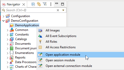
-
Restore the Configuration Errors panel. This panel is minimized in the top right corner.
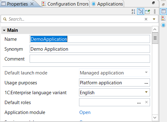
-
As a result, your workspace should look like this: On the left is the Navigator panel, in the center is the application module, and below it is the Configuration Errors panel.
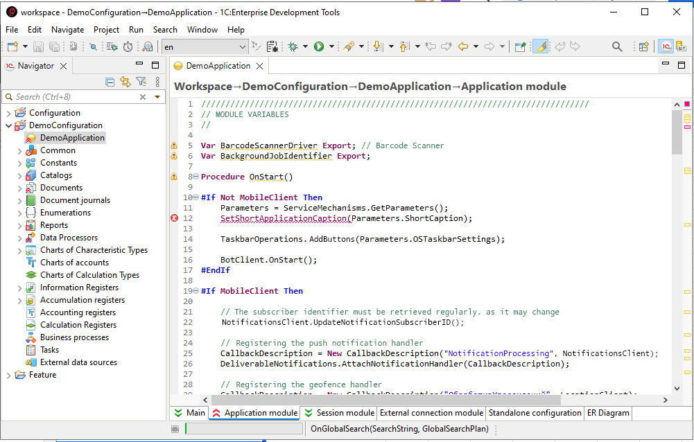
-
-
Look Around
-
You are currently in the master branch, as indicated in the project title.
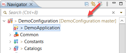
-
The Demo3 project contains 2,192 errors, as displayed in the Configuration Errors panel. This includes both language errors and errors related to configuration objects.
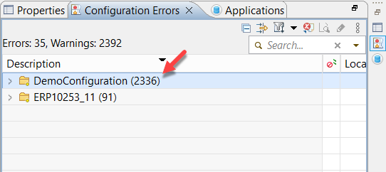
-
-
The cloned repository also contains another branch called feature/feature1. This branch was created to develop new functionality.
-
Switch to the remote tracking branch origin/feature/feature1 and choose to create a new local branch.
-
Take a look around. You are now in the feature/feature1 branch. The Demo3 project contains 2,193 errors. This includes both language errors and errors related to configuration objects. There is one additional error because a new line 13 was added to the application module with a warning:
FirstVariable = True. -
Hide all errors originating from the master branch. To do this:
-
Enable error hiding in the Demo3 project properties:
-
In the Navigator panel, right-click the project and select Properties from the context menu.
-
Go to the V8 > Validation > Settings for Validation Developers page.
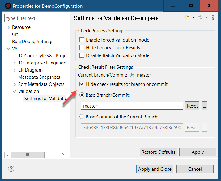
-
Enable the checkbox Hide check results for the selected branch.
-
In the Base Branch / Commit field, select the local branch master.
-
Click Apply and Close.
-
-
Click
(Hide/Show Errors from Base Git Branch) in the Main Window Command Bar.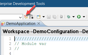
-
-
Look Around
-
All error markers in the module have disappeared except one. The remaining one is on the line added in this branch.
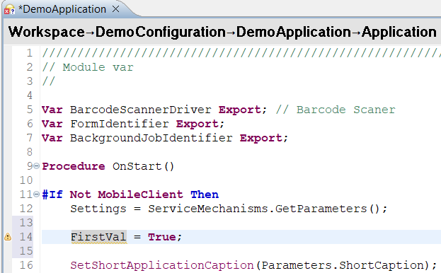
-
The Configuration Errors panel now shows 682 errors (previously 2,193). These remaining errors are not related to the 1C:Enterprise language.
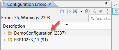
-
-
If you click
(Hide/Show Errors from Base Git Branch) again, all hidden errors from the master branch will reappear.
Setting Up Team Development
Before starting team development on a large project, it is necessary to configure Git. These settings will help avoid issues related to large files, different operating systems, and various encodings used by different developers.
Installing Git and Git LFS
1C:EDT has built-in Git support, so if you are working on training projects or small configurations, you can skip this section and proceed to the next one: Team Development Settings (config).
However, if you plan to modify standard 1C:Enterprise application solutions, you will need to install and configure Git LFS (Large File Storage). Git LFS is an extension for Git designed to handle large files and binary data, such as images, videos, audio files, 3D models, and similar data.
To configure Git LFS, you will need the Git command line. Therefore, you must first install Git.
-
Download and install Git: https://git-scm.com/
-
Download and install Git LFS: https://git-lfs.com/
-
Configure Git LFS for your account. To do this:
-
Enter "command prompt" in the search field.
-
Launch the command prompt.
-
Run the command:
git lfs installYou will receive the response:
Git LFS initialized.
-
After executing this command, Git will be configured with the necessary parameters to interact with Git LFS. You can view these settings by clicking Window > Preferences... > Version Control (Team) > Git > Configuration > User Settings, or by opening the configuration file, which is typically located in the user's directory C:\Users\Username\.gitconfig:
[filter "lfs"]
    required = true
    clean = git-lfs clean -- %f
    smudge = git-lfs smudge -- %f
    process = git-lfs filter-process
Now, if you clone a repository that uses Git LFS, you will be able to seamlessly fetch and push all project files.
However, if you want to create a new repository for your project using Git LFS, additional configuration specific to that repository will be required: Configuring Git LFS in a New Repository.
Team Development Settings (config)
These settings can be configured within 1C:EDT preferences or via the Git command line if Git is already installed on your computer.
To open Git settings in 1C:EDT preferences:
- Launch the 1C:EDT Start project.
- Click Window > Preferences... > Version Control (Team) > Git > Configuration > User Settings to open the Git configuration.
For example, to specify an email address, follow these steps:
- Click Add Entry.
- In the Key field, enter
user.email. - In the Value field, enter
johndoe@example.com. - Click Add.
The same actions can be performed from the command line using the following command:
git config --global user.email johndoe@example.comThe result will be the same.
All subsequent settings are described for use within 1C:EDT preferences, with matching command-line commands provided as reference.
Name and Email Address
When making your first commit, 1C:EDT will ask you to specify a name and email address, which will be used to identify your commits. This allows other developers to understand who made specific changes.
If you skipped this step or want to change these details, add the following parameters:
- user.name: your name
- user.email: your email address
When using the command line, execute the following commands:
git config --global user.name "John Doe"
git config --global user.email johndoe@example.com
Long Filenames
Your computer may have a file name length limit, such as 260 characters in Windows. Because of this, when cloning repositories or creating local repositories, you may encounter the error Filename too long.
To avoid this issue, follow these recommendations:
- Place local repositories as close to the root of the disk as possible.
- Launch 1C:EDT as an administrator and add the following parameter:
- core.longpaths: true.
Tip: To run 1C:EDT as an administrator:
- Close 1C:EDT.
- Close 1C:EDT Start.
- Use the command Start > 1C Enterprise Development Tools > 1CEDT Start to run 1C:EDT Start as an administrator (Run as Administrator in the context menu).
- Launch the 1C:EDT Start project.
- Open the team development configuration in 1C:EDT.
When working from the command line, execute the following command, the Git console must also be run as an administrator:
git config --system core.longpaths trueLarge Files
When working with a remote repository, issues may arise when executing Push to origin and Pull commands over HTTP if the repository contains large files. In such cases, increasing the http.postBuffer parameter can help.
Add the following parameter:
- http.postBuffer: 1048576000.
When using the command line, execute the following command:
git config --global http.postBuffer 1048576000More information about this parameter can be found in the Git documentation in English: git config http.postBuffer.
Line Ending Characters
If developers working on a project use different operating systems, Microsoft Windows, Linux, or macOS, it is necessary to configure line ending conversion when placing files in and retrieving them from the repository. The following commands configure Git so that developers' working copies use the native line endings for their operating systems, while the repository always stores files with LF endings.
Windows
Add the following parameters:
- core.autocrlf: true
- core.safecrlf: true
When using the command line, execute the following commands:
git config --global core.autocrlf true
git config --global core.safecrlf true
Linux and macOS
Add the following parameters:
- core.autocrlf: input
- core.safecrlf: true
When using the command line, execute the following commands:
git config --global core.autocrlf input
git config --global core.safecrlf true
More information about these parameters can be found in the Git documentation in English: git config core.autocrlf and git config core.safecrlf.
Troubleshooting: If you have not configured line endings and pushed your branch to the server, merging may detect differences in almost all files. To fix this and ensure the correct line endings in the server branch, follow this guide.
Russian Characters in Paths
Files with Russian characters may be displayed in an unreadable encoding.
To resolve this issue, add the following parameter:
- core.quotePath: false.
When using the command line, execute the following command:
git config --global core.quotePath falseFor more information on this parameter, refer to the Git documentation: git config core.quotePath.
Configuring Git LFS in a New Repository
If you have not yet installed Git and Git LFS, do so: Installing Git and Git LFS.
If you want your new repository to use Git LFS, the following settings must be applied after creating the repository but before making the first commit. Technically, you can enable Git LFS in an existing repository, but it is much more complex.
To configure Git LFS support in a repository, follow these steps:
-
Enter "command prompt" in the search field.
-
Launch the command prompt.
-
Navigate to the repository directory (where the .git directory is located).
-
Run the command:
git lfs installYou will receive the following response:
Updated Git hooks.
Git LFS initialized.
This command creates a special hook, pre-push, in the repository that transfers Git LFS files to the server when running the Push command.
-
Choose the file types to be managed by Git LFS. To do this, use the git lfs track command with the file extension specified. It is recommended to store all vendor configuration files, layout files with binary data, images, and archives in Git LFS. For example:
git lfs track "*.cf"
git lfs track "*.bin"
git lfs track "*.png"
git lfs track "*.gif"
git lfs track "*.bmp"
git lfs track "*.jpg"
git lfs track "*.zip"
You can track only specific types of *.bin files in Git LFS. For instance, you can enable tracking only for templates and modules without source code using the following pattern:
git lfs track "*/Ext/Template.bin"
git lfs track "*/Ext/Module.bin"
After executing these commands, a .gitattributes file will be created in the repository directory containing your settings.
-
Add the .gitattributes file to version control so that all developers using this repository follow the same tracking settings. To do this, run the command:
git add .gitattributes
Now you can make the first commit in this repository and then push the changes to the remote repository.
Keep in mind that not all Git servers support Git LFS. Additionally, servers that do support it implement it differently. Some enable it automatically for all repositories (such as GitHub), while others require explicit activation in the repository settings (such as Bitbucket).
Adjusting Timeout Settings for Remote Repositories
When working with remote repositories on other computers, low network performance may cause timeout errors. For example, a project import operation may fail with the following error:
Git repository clone failed.
Read timed out after 30,000 ms
In this case, try increasing the default remote connection timeout, which is set to 30 seconds. To do this, click: Window > Preferences... > Version Control (Team) > Git. Enter a higher value in the Remote connection timeout (sec) field.
Incorrect Line Endings in the Server Branch of Git
If you have not configured line endings and pushed your branch to the server, merging may detect differences in almost all files.
To fix this and standardize line endings in the server branch, follow these steps:
-
Delete the local copy of the remote repository you cloned earlier (select the Delete Git Repository Data and History and Also Delete Working Tree checkboxes).
-
In Git settings, configure (or modify) the following parameters:
-
core.autocrlf: false.
-
core.safecrlf: false.
-
-
Re-clone the remote repository.
-
Switch to your branch where the line delimiters need to be corrected.
-
Convert line delimiters to LF. To do this:
-
Select the project in the Navigator panel.
-
In the main menu, click: File > Convert Line Delimiters To > Unix.
-
Click Select All, then OK.
-
-
Commit the changes and push them to the server (only the files with incorrect line delimiters will be included in the commit).
-
Delete the local copy of the remote repository that you cloned in step 3.
-
Restore Git Settings. Ensure Git settings are properly configured:
-
For Windows:
-
core.autocrlf: true.
-
core.safecrlf: true.
-
-
For Linux and macOS:
-
core.autocrlf: input.
-
core.safecrlf: true.
-
-
-
Clone the remote repository again and continue working as usual.
Gradual Transition to Development in 1C:EDT
-
Evaluating the Need for Full Configuration Storage Conversion
-
Branch-Based Configuration Development Technology in Git Terms
Operation Flow
To explain the possibilities of gradually transitioning to development in 1C:EDT, it is necessary to first outline how team development is generally organized in 1C:Enterprise 8.
The general principle of group development is as follows. A configuration storage is created, into which the developed configuration is placed. Each developer on the team connects their infobase to this storage, locks the objects they need, and modifies them. Then, they return the objects to the storage and release them so that other developers can also modify them.
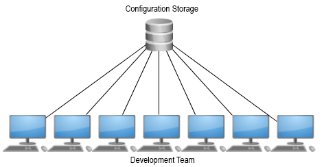
For large configurations, this workflow has two disadvantages. First, having a large number of developers significantly increases the likelihood that they will compete for the same resources (objects). Simply put, one developer will have to wait for another to finish their changes and release the locked objects. Second, when developing or modifying large sections of new functionality (technical projects), the configuration in storage will remain in an inoperative state until the technical project is fully completed and debugged. This means that during this time, it will be impossible to release, for example, a new version with bug fixes.
To eliminate these disadvantages, some time ago we introduced branch-based configuration development technology. You can fully familiarize yourself with this technology via the provided ITS link, but here we will explain its core concept. The idea is that for each technical project that is long-term and significantly impacts the configuration, a dedicated configuration storage is created: technical project storage.
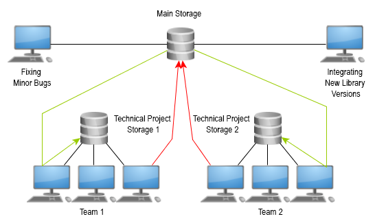
In simple terms, the configuration from the main storage is copied into this technical project storage. From that point, a small team working on the technical project interacts only with its technical project storage: making all necessary changes, debugging, and testing the results. Periodically, the technical project team updates its storage to reflect the latest state of the main storage to maintain an up-to-date version of the configuration they are refining. Once all work on the technical project is completed, the resulting configuration is merged into the main storage.
In this workflow, only a limited number of changes are made to the main storage. For example, bug fixes that do not require extensive coding, integration of new versions of libraries, and similar tasks. As a result, the main storage always remains in a functional state, allowing for the assembly of a scheduled configuration version at any time.
When discussing the gradual transition to development in 1C:EDT using the Git version control system, we assume that the current development process follows branch-based configuration development technology.
This gradual transition methodology allows most developers to continue working as before in Designer, while selected development teams can choose to execute all or some of their projects using 1C:EDT and Git. The overall organization of work in this case would look as follows.
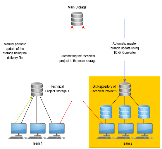
Project Team 1 continues working as before. They have a technical project storage (Project 1), where they carry out their development and periodically update it to match the main storage. At the end of development, Project Team 1 merges their changes into the main storage.
The Project 2 team works in a new way. They have a Git repository that is automatically updated to reflect the state of the main storage. This process is managed by a dedicated service configuration, 1C:GitConverter. The developers of Project 2 use 1C:EDT for development and rely on Git for version control. This means they leverage all the new development tools provided by 1C:EDT, along with the full capabilities of decentralized version control systems offered by Git. When Project 2 development is complete, they integrate their changes into the main storage using the same process as Project 1 developers, who follow the traditional approach.
This method offers several advantages.
-
It does not put critical technical projects at risk. Developers who have time and the ability to explore the new functionality can start transitioning to 1C:EDT. Teams working on critical projects can delay their transition to 1C:EDT.
-
It allows starting with simpler technical projects. Even within a single development team, they can begin transitioning to 1C:EDT with simpler projects while continuing to work on more complex ones using the old approach. As they gain experience, they can gradually shift more complex projects to 1C:EDT.
-
It provides time to adapt the existing development infrastructure to 1C:EDT and Git. This applies to both software and hardware. Large projects often include auxiliary tools for automating build, debugging, and testing processes. These tools are typically configured to interact with configuration storage. A gradual transition allows adapting them to interact with Git repositories, testing their functionality, and ensuring stability. Developers can also gradually upgrade their computers since developing in 1C:EDT requires more computing power compared to Designer.
-
It offers the ability to revert to the previous workflow. If unexpected issues arise, the development team can create a project storage, transfer the configuration from the Git repository, and return to the old workflow. More details on this can be found in section How to Revert to the Previous Workflow.
Important: If your team uses a single configuration storage for group development or multiple storages following a custom approach, transitioning to 1C:EDT gradually requires defining a logical development area that can function independently for some time. This area can then be migrated to 1C:EDT according to the steps described below.
Evaluating the Need for Full Configuration Storage Conversion
Before starting development, the main configuration storage needs to be converted into a Git repository for developers to interact with. Configurations vary in structure, and their development histories also differ.
A full conversion of the configuration storage may require significant time and powerful technical resources. Before proceeding with the following steps, assess whether a full storage conversion is necessary.
You have two options.
-
Fully convert all versions of the configuration storage into a Git repository, then gradually develop projects in 1C:EDT. This approach retains the complete history of the storage in the repository but may take a considerable amount of time.
-
Convert only the latest version of the configuration storage and then partially develop projects in 1C:EDT. In this case, the version history in the configuration storage will not be available in 1C:EDT, but the transition time to partial development in 1C:EDT will be minimized. For more details on this process, refer to the 1C:GitConverter documentation in the section Starting Work in EDT Without Converting All Previous Storage Versions.
To help you estimate the technical and time costs, here are some examples from our experience. We have used the partial development methodology in 1C:EDT for several configurations. The storages for these configurations have been fully converted into Git repositories. The following table presents the parameters of these configurations, the specifications of the computers used for conversion, and the time required for the process.
| 1C:User Internet Support Library | Service Manager | 1C:ERP Enterprise Management 2 | |
|---|---|---|---|
| Configuration Storage Parameters | |||
| Storage Size (MB) | 725 | 500 | 31,000 |
| Number of Versions | 1,500 | 4,200 | 49,500 |
| Number of Files in the First Version | 0 | 0 | 25,592 |
| Number of Files in the Latest Version | 3,430 | 5,875 | 58,361 |
| 1C:GitConverter Settings | |||
| Execution Queues | No | Used | Used |
| Incremental Configuration Export | No | Used | Used |
| Computer Specifications and Time | |||
| Virtual | yes | No | No |
| Number of Cores | 2 × 3.6 GHz Xeon | 8 × 3.6 GHz Core-i7 | 24 × 3.6 GHz Xeon |
| RAM | 8 GB | 16 GB | 96 GB |
| Disk | HDD | SSD 50 GB | SSD 800 GB |
| Full Storage Conversion Time | 26 hours | 32 hours | 27 days |
Evaluate the parameters of your configuration and storage, as well as the computing power you are willing to allocate for this task. You may need to conduct several practical experiments to determine the speed at which you can convert your storage.
After that, choose one of the two working options mentioned at the beginning of this section.
Branch-Based Configuration Development Technology in Git Terms
If you are not very familiar with Git's structure and terminology, this section will help you navigate the new terms and, if necessary, find more detailed information about them. Below is a list of concepts you are accustomed to when working in Designer. For each of them, there is a respective Git concept or operation with a similar meaning.
Technical Project Storage
In Designer, this is the configuration storage.
In 1C:EDT, the technical project storage is a remote Git repository. You can read more about remote repositories in section Remote Repositories.
Connecting to Configuration Storage
In Designer, this operation replaces the main configuration with the configuration stored in the technical project storage. This operation allows you to begin using Designer with the configuration stored in the repository.
In 1C:EDT, similar actions are performed by cloning the remote repository and importing its data into the project. Read more about cloning in section Cloning a Repository.
Locking in Storage
In Designer, to begin modifying an object, you need to lock it in the technical project storage.
In 1C:EDT, this action is not required. You can modify any configuration objects independently of other developers. Each developer commits their changes to their local repository independently of others. More details can be found in section Commit Changes to the Local Repository (commit).
Concurrent Work in Storage
In Designer, while another developer is modifying an object, you cannot do anything with that object. Only after the other developer has completed their changes, committed them to the storage, and unlocked the object can you lock it for your modifications.
In 1C:EDT, developers make changes independently and send them to the remote repository on their own. If, at the time of sending, another developer has already pushed changes, you must first fetch the latest changes from the server, merge them with your modifications, and then push your updates. If conflicts arise during the merge, for example both developers modified the same module, you must resolve them locally using the Compare and Merge Configurations Editor. A typical example of team development can be found in section Simple Development Example.
Comparing and Merging Configurations
In Designer, this operation transfers changes from one configuration, usually represented as an export file, to another configuration being edited.
In 1C:EDT, similar actions occur during branch merging. Read more about branches and merging in section Branching.
Committing to Storage
In Designer, this operation transfers modified objects from the main configuration to the technical project storage.
In 1C:EDT, similar actions are performed using the commands Commit... and Push to origin.
Updating Configuration from Storage
In Designer, this operation merges changes from the technical project storage into the main configuration.
In 1C:EDT, similar actions are performed using the command Pull.
Using a Git Repository for Technical Project Storage
Classic Git-based team development methods assume that a repository always has a main branch called master. This branch is intended to store a version of the configuration that is always ready for release. If a modification is needed, such as a bug fix, a topic branch is created for the fix and testing. After making sure that everything is functioning correctly, you merge the feature branch into the main master branch. Thus, the master branch always contains the next functional version of the configuration.
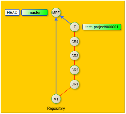
If you follow a gradual transition to 1C:EDT where the repository is used for technical project storage, this classic approach to branches is altered. The difference is as follows.
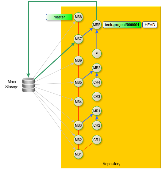
The master branch is used solely to store the current state of the main configuration storage. This is managed by the service configuration 1C:GitConverter, which automatically updates the master branch periodically (commits MS1, MS2, etc., where "MS" stands for "Main Storage"). Developers do not make changes to the master branch or merge other branches into it.
A dedicated branch is created to store project changes. In the diagram, this branch is named tech-project/000001. Developers modify the configuration within this branch (commits CR1, CR2, CR3, CR4, F, where CR stands for Correction and F stands for Final).
Periodically, developers merge the master branch into the tech-project/000001 branch to keep it updated with the latest state of the Main Storage configuration (commits MR1, MR2, MRF, where MR stands for Merge and MRF stands for Final Merge).
When the project development is complete and has been tested (commit F), the configuration from the tech-project/000001 branch needs to be integrated into the Main Storage. To do this, the latest state of the Main Storage (commit MS7) is imported into the master branch, and then the master branch is merged into the tech-project/000001 branch (commit MRF).
Next, the project is imported into the infobase and transferred to the Main Storage using the method described in the branched configuration development technology, just as if it had been developed in a dedicated project configuration storage.
1C:GitConverter
General Information about the Configuration
The 1C:GitConverter configuration is designed to:
-
Perform the initial conversion of a configuration storage into a Git repository.
-
Automatically update the master branch of the remote repository with the current state of the configuration from the main storage on a scheduled basis.
-
Additionally, 1C:GitConverter provides other service capabilities, but they are not needed for this task.
The 1C:GitConverter configuration is free, and you can download it from:
-
On ITS: 1C:GitConverter.
-
From the public GitHub repository of the 1C company: 1C-Company / GitConverter.
This configuration can simultaneously convert and synchronize multiple configuration storages and repositories. To understand how it works, let’s consider an example with a single configuration storage synchronized with a remote repository.
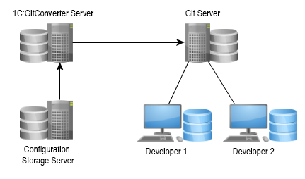
The computer where the server-based infobase with the 1C:GitConverter configuration is installed will be referred to as 1C:GitConverter Server. 1C:GitConverter retrieves data from the configuration storage, converts it into the 1C:EDT format, and commits it to the local repository located on the 1C:GitConverter server.
Then, it sends these changes to a remote Git repository hosted on another computer, which we will call Git Server. This remote repository serves as the “project storage” for the development team (Developer 1 and Developer 2).
1C:GitConverter sequentially reads versions of the configuration from the storage and converts them. The process of converting a version consists of the following stages:
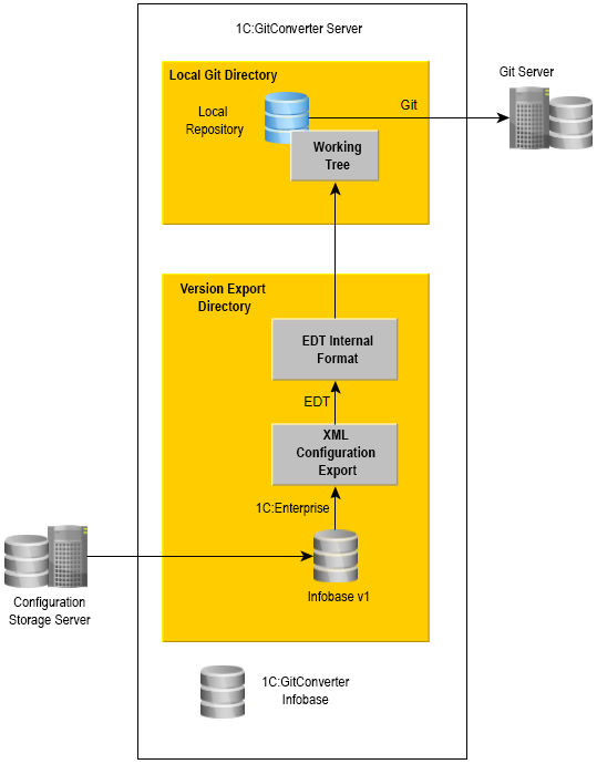
-
Using the command-line interface of 1C:Enterprise, an infobase is created in the version export directory, where the next version is retrieved from the storage.
-
This version is then exported from the infobase as .xml files.
-
Using the 1C:EDT command-line interface, the .xml export of the configuration is converted into 1C:EDT internal format files.
-
The internal format EDT files are placed in the working tree, which is located in the local Git directory.
-
Git commands are used to commit changes to the local repository and push them to the remote repository.
From this scheme, it is important to understand that when configuring storage conversion in 1C:GitConverter, you need to specify two directories:
-
Version export directory,
-
Local Git directory.
For optimal performance, both directories should be on the same logical disk. This allows the operating system to move versions instead of copying data, which would otherwise take additional time.
Additionally, from this scheme, you can see that the 1C:GitConverter server requires the following software to be installed. Details can be found in section 1C:GitConverter Server Setup.
-
The server and client of 1C:Enterprise to run the 1C:GitConverter configuration.
-
1C:Enterprise clients of the versions used in the configuration storages you plan to convert.
-
A DBMS supported by 1C:Enterprise to store the 1C:GitConverter infobase.
-
1C:EDT to convert exported .xml configuration files to the 1C:EDT format.
-
Git to commit changes to the local repository and push them to the remote repository.
The 1C:GitConverter configuration includes optional features that you may find useful. These features include:
-
Using Git LFS to store large binary files outside the repository, improving repository performance.
-
Execution Queues to balance the load of background tasks by limiting the number of operations run at once.
-
Storage Copies to load versions from a single configuration storage in parallel.
Before proceeding, it is recommended to review these features. For example, the decision to use Git LFS should be made before you start using 1C:GitConverter, based on the size of your configuration storage, the number of versions it contains, and whether vendor configurations are included. Other features can be enabled later as needed.
Git LFS
Git Large File Storage (LFS) is a Git extension for versioning large files. Instead of storing large files such as audio, video, datasets, or graphics in Git, LFS replaces them with text pointers while keeping the actual files on a remote server like GitHub.com or GitHub Enterprise.
For large 1C:Enterprise configurations, storing binary files directly in the repository can cause performance issues. To avoid slowdowns, it is recommended to use Git LFS for vendor configuration files, binary layout files, and images.
We recommend enabling Git LFS if:
-
The configuration storage exceeds 300 MB and contains more than 1,000 versions.
-
The configuration storage exceeds 100 MB and includes vendor configurations.
Most Git servers, including GitLab, GitHub, and BitBucket, support Git LFS. It only needs to be enabled for your project.
However, Git LFS must be installed separately on the 1C:GitConverter server and on developers’ local machines before the first commit is made.
Installation and setup instructions can be found in the 1C:GitConverter documentation under Git LFS.
Execution Queues
Execution queues limit the number of operations run by background tasks. There are two types of operations: exporting configurations and loading metadata.
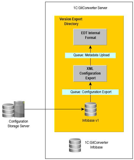
Queues can be assigned to specific configuration storages or shared across the entire 1C:GitConverter infobase.
There are two main reasons for using execution queues.
First, this reduces excessive load on the resources of the 1C:GitConverter server. If you notice high disk or memory usage, execution queues can help manage system resources by limiting the number of operations run at once.
Second, queues are needed if you are converting a large configuration and want to speed up the process by using an incremental configuration export instead of a full export. This feature is available in 1C:Enterprise starting from version 8.3.10.
Configuration
To enable execution queues, select Service > Use Execution Queues > Use Execution Queues.
The list of execution queues is available in any configuration storage form under Execution Queues.
If a queue is shared, versions are selected based on their date. This should be considered when converting projects with long histories and newer projects within the same 1C:GitConverter infobase.
If a queue is assigned to a specific storage, at least two queues need to be created for each storage.
- Configuration Export. Starting from 1C:Enterprise version 8.3.10, incremental exports can be used. Versions must be exported in sequence, so only one export queue should be created.
- Metadata Loading.
Each queue should specify how many operations, configuration versions, to process at a time. Additionally, you can define version ranges to separate workloads across different queues and set up an execution schedule.
Storage Copies
Storage copies allow configuration versions to be retrieved more quickly by running the process in parallel.
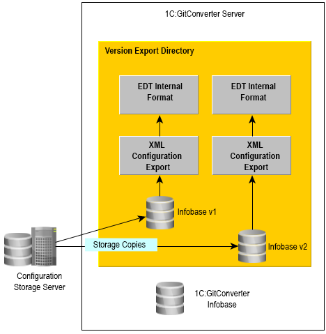
This is especially useful when converting large configurations, where retrieving versions can take a long time. During this process, resources allocated for exporting and converting to the 1C:EDT format might otherwise remain idle.
Configuration
The list of storage copies is available from the configuration storage form under the link Storage Copies.
You can use the same server storage address for copies but with different user accounts.
The number of copies affects the size of the global version cache created on the configuration storage server. The cache size must be configured.
To configure it, open the infobase in Designer that is connected to this storage and specify the global cache size. Go to Configuration > Configuration Storage > Storage Administration... > Other > Global Configuration Version Cache.
Set the maximum cache size to be 1.5 to 2 times larger than
<size of one version in MB> * <number of storage copies>You can use the address of an archive copy of the storage if versions have been reduced in the current configuration storage. In this case, set a version number limit for the copy and define a schedule for retrieving versions from it. If the copy uses the main storage address, you need to schedule retrieval tasks with intervals that ensure smooth operation for developers.
Software Installation and Configuration
You will need to install and configure the software on four computers (groups).
Configuration Storage Server Setup
For converting the storage and synchronizing it with the repository, we recommend using a configuration storage server. From our experience, it works significantly faster than a simple file storage system in this scenario.
Ensure that the version of 1C:Enterprise used for the storage is supported by the version of 1C:EDT (1.8.1 or later) that you will install on the 1C:GitConverter server. If it is not, convert the configuration storage to the required platform version.
If you plan to use storage copies, configure the global cache size as described in the Storage Copies section.
1C:GitConverter Server Setup
Setting up the 1C:GitConverter server consists of three steps.
Git Server Setup
As a Git server, you can use one of the public repository management systems available online. For example, GitLab, GitHub, BitBucket, and others.
The advantage is that no prior software installation or configuration is required.
The downside is that hosting a remote repository may require a paid account.
However, GitLab provides a free version that you can download and install on your organization's server.
Configuring Git on Developer Workstations
The following configuration steps must be run on each developer's workstation involved in the team development of the technical project in 1C:EDT.
-
Install the same version of 1C:EDT that is installed on the 1C:GitConverter server. Matching versions is important because the 1C:EDT version used to edit the configuration is saved in the 1C:EDT project.
-
If you chose to use Git LFS when converting the storage to a repository, install and configure Git LFS on the developer's computer as described in the Git LFS section.
-
Configure Git for collaboration as described in the 1C:EDT documentation under Team Development Settings.
1C:GitConverter Server Setup
Software Installation
The following software must be installed on the 1C:GitConverter server:
-
The 1C:Enterprise platform for the 1C:GitConverter infobase.
-
A DBMS for the 1C:GitConverter infobase.
-
The 1C:Enterprise platform versions that are used by the configuration repositories you plan to convert.
-
1C:EDT.
-
Git.
-
Git LFS (if you decide to use LFS).
-
Install the 1C:Enterprise platform version 8.3.12.1412 or later. You will need both the server and client components.
All conversion commands for each version will be executed under the operating system account of the user running the 1C:Enterprise server service.
-
Install any DBMS supported by 1C:Enterprise.
-
Create a new server-based infobase and load the 1C:GitConverter configuration into it.
Running this configuration in file mode should only be used for demonstration purposes.
-
Open Designer and configure the log settings for this infobase.
The event intensity in the 1C:GitConverter infobase can be very high, while the historical log data is of little value. Therefore, you can either disable the log entirely or configure it to record only errors and set up archiving and deletion of old log files. To do this, go to: Administration > Event Log Options...... > Do Not Register, or Register Errors and specify the minimum period you need.
-
Install the 1C:Enterprise client versions that match those used by the configuration repositories you plan to convert.
-
Install 1C:EDT version 1.8.1 or later.
-
It is important that only one version of 1C:EDT is installed on the 1C:GitConverter server. If multiple versions are installed, remove the unnecessary ones.
-
Ensure that the console mode components of 1C:EDT are correctly installed. To do this, run the following command in the command line:
ring edt platform-versions -
To enable the ring utility to correctly output messages to a shared log file, add the following environment variable to the operating system: RING_OPTS with the value:
-Dfile.encoding=UTF-8Fastpath: To display all messages from the ring utility and 1C:EDT in Russian, set the RING_OPTS variable to:
-Dfile.encoding=UTF-8 -Dosgi.nl=ru
-
-
Install Git version 2.16 or later. You can download the Git installation package from: http://git-scm.com/downloads.
-
If you plan to use Git LFS, install and configure it on the 1C:GitConverter server as described in the Git LFS section.
Configuring 1C:GitConverter
Once all necessary software is installed on the 1C:GitConverter server, configure the parameters of 1C:GitConverter.
There are general settings for the entire configuration and specific settings for converting each individual storage.
General Configuration Settings
- Specify the folder on the 1C:GitConverter server where the binary files of the 1C:Enterprise platform are located. To do this, navigate to Service > Path to platform versions on the server.
The path should be specified using a template with the %PlatformVersion% parameter, for example:
C:\Program Files (x86)\1cv8\%PlatformVersion%\binWhen converting a specific configuration storage, the program will replace %PlatformVersion% with the version specified in the storage properties in the 1C:GitConverter infobase.
- If you decide to use execution queues, configure them as described in the Execution Queues section.
Configuring Conversion for a Specific Configuration Storage
For each configuration storage you plan to convert, create an individual entry in the Configuration Storages catalog. Instructions on how to fill in the properties of this entry are available in the 1C:GitConverter documentation under Conversion Parameters.
Additionally, for each storage, define the correspondence between its users and the name and email address that will appear in repository commits. More information can be found in the 1C:GitConverter documentation under User Information.
Creating a Local Repository
After creating and saving a catalog item describing the configuration storage, you can create a respective local repository on the 1C:GitConverter server. In the form of this entry, next to the Local Git Directory field, click Create Git Repository and Apply Initial Settings. The local repository created this way will have the following features.
A .gitattributes settings file will be created, including binary file settings:
*.bin binary
*.axdt binary
*.addin binary
An exclusion file .gitignore is created, where the files DumpFilesIndex.txt and ConfigDumpInfo.xml are added. These files do not need to be stored in the local repository.
Local repository settings are configured for more convenient use:
git config --local core.quotepath false
git config --local gui.encoding utf-8
git config --local i18n.commitEncoding utf-8
git config --local diff.renameLimit 1
git config --local diff.renames false
Additionally, settings for line endings are added:
git config --local core.autocrlf true
git config --local core.safecrlf warn
This ensures that files in the repository will have LF line endings, and if a file contains a mix of CRLF and LF, a warning will be logged.
Team Development Examples for a Technical Project
Simple Development Example
Let’s consider a simple example of team development that can be used in a technical project team.
At this point, there is a remote repository where the configuration has been converted from the main storage. The project manager has created a branch in it, tech-project/000001, where the development will take place. The project team consists of two developers: Michael and James.
The first developer, Michael, clones the remote repository. To do this, he switches to the Git perspective and runs the command from the Git Repositories panel  (Clone a Git Repository). For development, he only needs the tech-project/000001 branch, so in the repository cloning wizard, he selects only that branch.
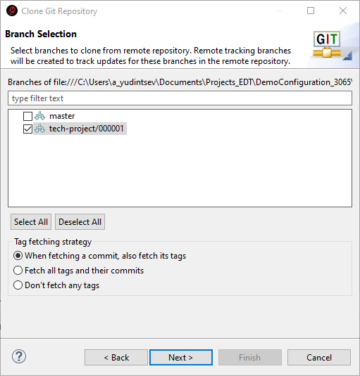
Then, he makes changes and creates a local commit 88a45e3 (Version Control (Team) > Commit...).
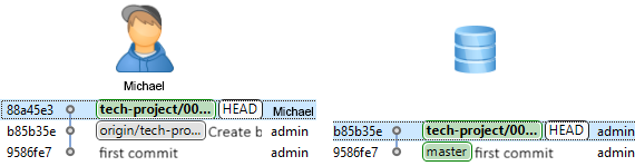
The second developer, James, does the same—cloning the remote repository and making a commit with changes e81fdd8.
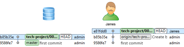
Now, James pushes his changes to the server (Version Control (Team) > Push to origin).
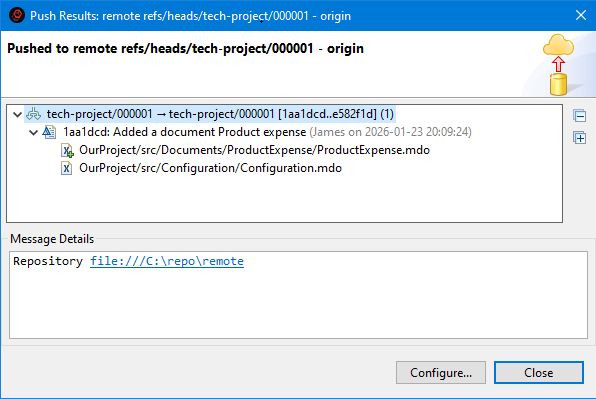
The commit history of his local repository and the remote repository now match.
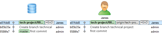
Michael also tries to push his changes to the server.
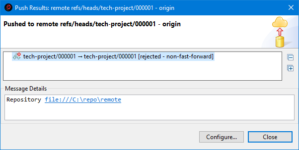
However, he is unable to do so because James has already pushed his changes. It is very important to understand that these two developers did not edit the same object. When using Git, even if different objects were edited, you must merge commits locally.
Before Michael can push his changes to the server, he needs to retrieve James’ updates and then perform a merge. This is done with a single command Version Control (Team) > Pull.

The merge completes successfully—Michael’s commit history now looks like the illustration.
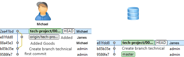
Now, Michael can test his code to ensure it still functions correctly and then push his work, now merged with James’ work, to the server.
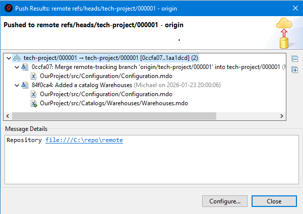
As a result, Michael’s commit history looks as shown in the illustration.
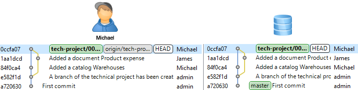
Meanwhile, James has been working on a feature branch. He created a feature branch named Project54 (Version Control (Team) > Switch To > New Branch...) and made three commits in this branch. He has not yet pulled Michael’s changes, so his commit history appears as shown in the illustration.
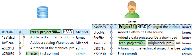
James wants to synchronize his work with Michael’s, so he fetches updates from the server (Version Control (Team) > Fetch from Upstream).
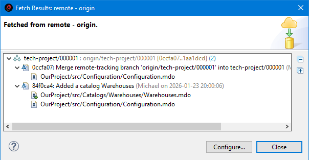
This command retrieves Michael’s updates that he has already pushed. James’ commit history now looks as shown in the illustration.
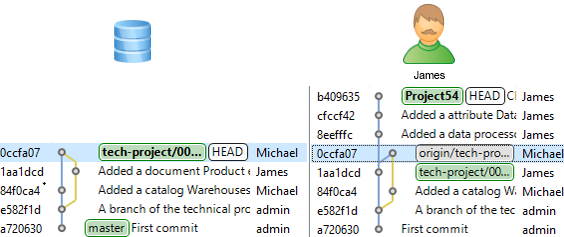
Now, James can merge his feature branch into the tech-project/000001 branch, incorporate Michael’s work (origin/tech-project/000001) into his branch tech-project/000001, and then push the changes to the server.
First, he switches to his main branch, tech-project/000001, to combine all the work (Version Control (Team) > Switch To > tech-project/000001).
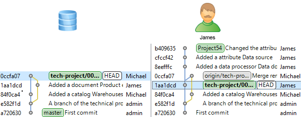
He can merge either origin/tech-project/000001 first or Project54—since both are ahead in the commit history, the merge order does not matter. The final state of the repository will be identical regardless of the merge order, with only slight differences in commit history.
He decides to merge the Project54 branch first (Version Control (Team) > Merge... > Project54).
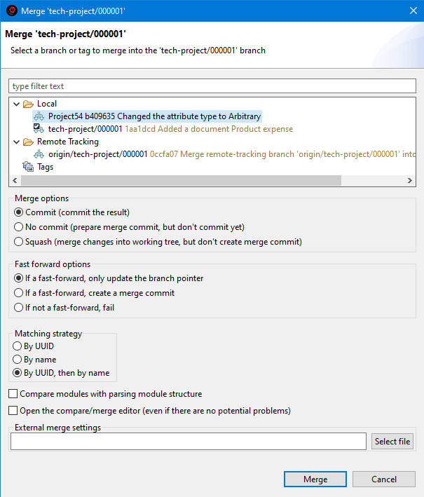
No issues occur. As you can see, this was a simple fast-forward merge.
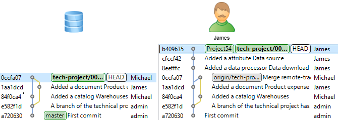
Now, James merges Michael’s work (origin/tech-project/000001).
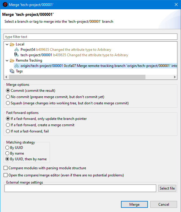
The merge completes successfully, and now James’ commit history looks as shown in the illustration.
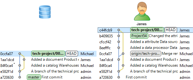
Now, the origin/tech-project/000001 pointer is available from James’ tech-project/000001 branch, so he can safely push his changes to the server (assuming Michael has not pushed new changes in the meantime).
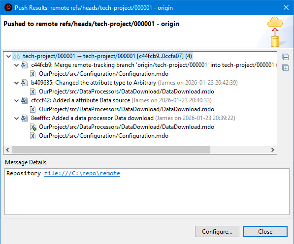
As a result, James’ commit history appears as shown in the next illustration. Each developer made multiple commits and successfully merged their work with the other’s.
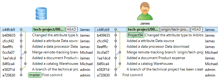
This is one of the simplest workflows. You develop for some time, primarily in a feature branch. When you are ready to share this work with others, you merge it into the tech-project/000001 branch, fetch updates from the server, and merge origin/tech-project/000001 (if changes occurred in the meantime), and finally, push your changes to the tech-project/000001 branch on the server. # The overall sequence of actions is shown in the illustration:
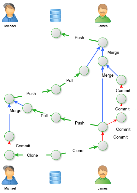
Updating a Repository Branch Based on the Main Storage
Some time after the start of the technical project development, several errors were fixed in the main storage. The project manager decides to update the repository to match the main storage.
To do this, they fetch changes from the remote repository (Version Control (Team) > Fetch from Upstream).
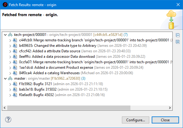
As you can see, changes made in the main storage and automatically transferred to the repository by the 1C:GitConverter configuration will be received in the master branch. Meanwhile, changes made by Michael and James during this time will be received in the tech-project/000001 branch.
As a result, the project manager’s commit history will look as follows:
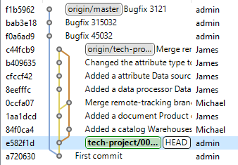
Their main branch is tech-project/000001, so they can perform Pull to merge Michael and James' changes (origin/tech-project/000001).
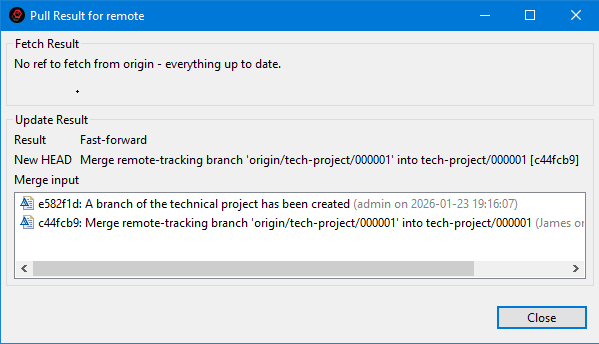
As a result, their commit history will appear as follows.
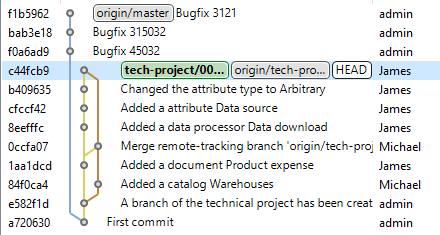
Now they can merge the remote origin/master branch into their local tech-project/000001 branch to integrate the changes from the main storage.
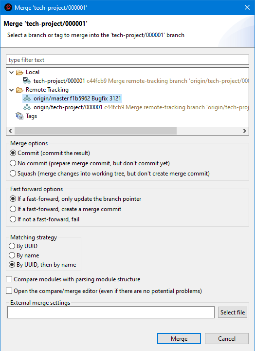
As a result, their commit history will appear as follows.
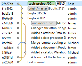
After this, they test the application to ensure it still functions correctly. Then, they push the tech-project/000001 branch to the server so that Michael and James can use the updated version of the developed application solution.
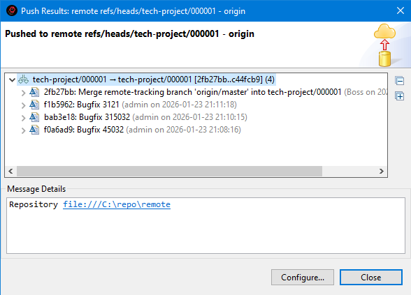
As a result, the commit history on the server appears as follows.
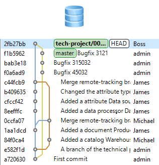
The project manager notifies Michael and James that the technical project branch has been updated. Therefore, before making further changes, Michael first retrieves the latest updates from the server and merges them into his local branch (Version Control (Team) > Pull).
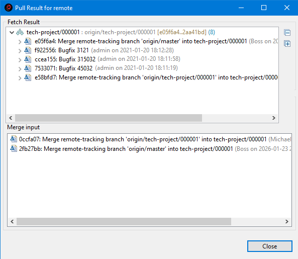
As a result, Michael’s commit history matches that of the remote server.
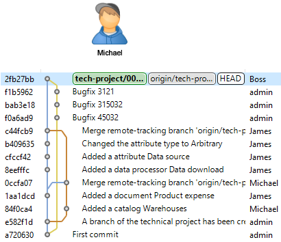
How to Revert to the Previous Workflow
If at any point you decide to revert to the previous workflow with the technical project repository, you can do so. Suppose the configuration development in the repository has reached the following stage:
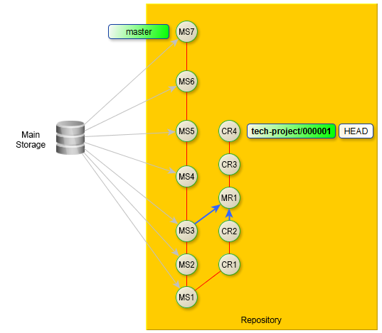
The diagram uses the following commit notations:
-
MS: Main storage
-
CR: Correction
-
MR: Merge
In this case, you need to take the following steps:
-
Switch to the master branch (Version Control (Team) > Switch To > master).
-
Check out the last commit from this branch that was merged into the tech-project/000001 branch (Ox3) (Check Out in the History panel).
-
Export the retrieved configuration to any infobase.
-
From this infobase, create a delivery file (*.cf).
-
Based on this delivery file, create a technical project repository as described in the branched configuration development technology (Appendix 1).
-
Switch to the tech-project/000001 branch (Version Control (Team) > Switch To > tech-project/000001).
-
Check out the last commit from this branch (Cr4) (Check Out in the History panel).
-
Export the retrieved configuration to any infobase.
-
Save the configuration of this infobase to a file.
-
Update the technical project repository with this configuration file.
-
After this, you can continue working as outlined in the branched configuration development technology.
Using Git When Editing Projects
Hide Language Errors of the Main Branch
Large projects may contain a significant number of inherited errors that do not affect the application's functionality but mainly involve violations of coding standards.
When working on a task, usually done in a separate branch, you can hide errors from the main branch to see only your own errors introduced in the current branch.
Troubleshooting: The following scenario only hides errors related to 1C:Enterprise language. Errors related to metadata structure will remain visible.
For example, you are in the master branch and plan to start working on task issue-45:
-
Create a new branch issue-45.
-
In the Navigator panel, click Properties > V8 > Validation > Settings for Validation Developers in the project's context menu.
-
Enable the checkbox Hide check results for the selected branch.
-
In the Base Branch / Commit field, select the branch relative to which you want to view only the errors you introduced. In this case, it is the master branch.
-
Click Apply and Close.
-
In the Main Window Command Bar, click
(Hide/Show Errors from Base Git Branch). After this:-
All markers related to errors from the master branch will disappear in the modules.
-
All messages about language errors from the master branch will be removed from the Configuration Errors panel.
-
-
To display all project errors again, click
(Hide/Show Errors from Base Git Branch) once more.
See an example of how this feature is used.
By default, the base branch/commit is set to the current commit (HEAD). Thus, if you simply enable the checkbox Hide validation results for the selected branch, you will see only the errors present in your unstaged changes.
To reset the Base Branch / Commit field to its default HEAD value, click Reset.
The Base Commit of the Current Branch toggle allows you to select a base commit from the Git Reflog.
Note: The older the selected base commit (the further back it is from HEAD), the longer the analysis and filtering preparation will take. Hiding old errors will happen gradually as comparisons and analyses are completed. If HEAD or HEAD~1 is used as the base commit, the analysis is typically completed very quickly, provided the Git index is already built.
Find the Author of Each Line in a Module
The 1C:Enterprise Language Editor can display information about the author and commit in its vertical ruler. You can configure how this information is displayed.
Show Commit Information
- Open the module in the 1C:Enterprise Language Editor.
- Click Show Revision Information in the vertical ruler's context menu.
Show Commit in the History Panel
- Hover over the commit marked in the vertical ruler.
- Click show in history in the pop-up window.
- 1C:EDT will open the History panel and highlight the commit that introduced the changes.
Open Commit in the Viewing Panel
- Hover over the commit marked in the vertical ruler.
- Click open commit in the pop-up window.
- 1C:EDT will open the commit in the viewing panel.
Hide Commit Information
Click Revisions and then Hide Revision Information in the vertical ruler's context menu.
Display Author and Commit Identifier
To display the commit author's name and commit identifier in the vertical ruler, select the following options from the context menu:
- Revisions > Show Author
- Revisions > Show ID
Configure Commit Coloring
There are several options for coloring commits displayed in the vertical ruler. To select one, click Revisions in the context menu of the vertical ruler.
- Color by Date: newer commits are highlighted with a darker background.
- Color by Author: changes made by each author are highlighted with a unique background color.
- Combined Coloring: changes made by each author are highlighted with a unique background color. Newer commits are highlighted with a darker background.
Graphical Interface and Command Line
You may have worked with Git before and used console commands. This approach is not recommended in 1C:EDT.
It may cause some inconveniences. For example, after checking out a branch, you might need to refresh the project state in the Navigator panel.
It can also lead to additional difficulties. If a merge or cherry-pick operation results in a conflict, you will need to resolve it at the .xml file level, which is not always easy. To simplify these operations, 1C:EDT provides a comparison and merge editor that works with configuration objects instead of files. This makes merging more intuitive. However, this editor is only available when working interactively in 1C:EDT.
1C:EDT has built-in Git support. All version control actions are run interactively using commands available in different panels. For example, in the Navigator panel, Git commands are located in the project’s context menu under the Version Control (Team) group. These commands become available once you place your project under version control.
Additionally, 1C:EDT includes the Git perspective, which serves as the main workspace for working with Git, independent of specific development tasks.
Git Commands in the 1C:EDT Graphical Interface
Below is a reference list of Git commands and their matching interactive commands in 1C:EDT.
Add, Amend, Branch, Checkout, Cherry-pick, Clean, Clone, Commit, Config, Diff, Fetch, Init, Log, Merge, Pull, Push, Rebase, Reflog, Remote, Repository, Reset, Revert, Rm, Stash, Status, Tag.
Add
- Git Documentation: git add
- Name in 1C:EDT:
 Add Selected Files to Index, Add All Files to Index, Add to Index
 - Scenario: Add Changes to Index
Amend
- Git Documentation: git commit --amend
- Name in 1C:EDT:
 Amend, Edit Previous Commit
 - Scenario: Amend Last Commit
Branch
- Git Documentation: git branch
- Name in 1C:EDT: Create New Branch..., Create Branch..., Configure Branch..., Rename Branch..., Delete Branch
- Scenarios: Creating a New Branch, Rename Branch, Deleting a Branch
Checkout
- Git Documentation: git checkout
- Name in 1C:EDT: Switch To, Check Out
- Scenario: Switch to Another Branch
Cherry-pick
- Git Documentation: git cherry-pick
- Name in 1C:EDT: Cherry-Pick...
- Scenario: Cherry-Pick
Clean
- Git Documentation: git clean
- Name in 1C:EDT: Clean...
Clone
- Git Documentation: git clone
- Name in 1C:EDT: Clone a Git Repository, Clone Repository...
- Scenario: Cloning a Repository
Commit
- Git Documentation: git commit
- Name in 1C:EDT: Commit, Commit...
- Scenario: Commit Changes to the Local Repository
Config
- Git Documentation: git config
- Name in 1C:EDT: Configuration
- Scenario: Team Development Settings
Diff
- Usage in 1C:EDT docs: differences, Show Unified Diff
- Note: not used for 1C:Enterprise application-level comparison, use configuration comparison scenarios instead
Fetch
- Git Documentation: git fetch
- Name in 1C:EDT: Fetch, Fetch From..., Fetch from Origin, Fetch from Upstream
- Scenarios: Fetch from Origin, Fetch from Any Remote Repository
Init
- Git Documentation: git init
- Name in 1C:EDT:
 Create a New Git Repository
 - Scenario: Create a Local Repository
Log
Merge
- Git Documentation: git merge
- Name in 1C:EDT: Merge
- Scenarios: Merge This Branch, Merge Arbitrary Branch
Pull
- Git Documentation: git pull
- Name in 1C:EDT: Pull
- Scenarios: Pull from Upstream Repository, Pull from Any Remote Repository
Push
- Git Documentation: git push
- Name in 1C:EDT: Push, Push Commit..., Push Branch..., Push to origin, Commit and Push...
- Scenarios: Push to Origin, Push Master Branch, Push to Any Remote Repository
Rebase
- Git Documentation: git rebase
- Name in 1C:EDT: Rebase, Rebase HEAD on, Interactive Rebase
- Scenarios: Rebase the Current Branch onto Another Branch, How to Undo a Rebase, Perform an Interactive Rebase
Reflog
- Git Documentation: git reflog
- Name in 1C:EDT: Git Reflog
Remote, Remote Repository
- Git Glossary: remote repository
- Name in 1C:EDT: Remote Repository, Create Remote Repository..., Delete Remote Repository
- Scenario: Remote Repositories
Repository
- Git Glossary: repository
- Name in 1C:EDT: Git Repositories
Reset
- Git Documentation: git reset
- Name in 1C:EDT: Reset, Reset...
- Scenario: Reset Changes in the Working Tree to a Specific Commit
Revert
- Git Documentation: git revert
- Name in 1C:EDT: Revert Commit
- Scenario: Revert to a Previous State
Rm
- Git Documentation: git rm
- Name in 1C:EDT: Remove from Version Control
Stash
- Git Documentation: git stash
- Name in 1C:EDT: Stash Changes..., Stashes
- Scenario: Stash Changes
Status
- Git Documentation: git status
- Name in 1C:EDT: Git Staging, Git Repositories, label decorations
Tag
- Git Documentation: git tag
- Name in 1C:EDT: Create Tag..., Delete Tag
- Scenario: Create a Tag
Changes
Commit Changes to the Local Repository (commit)
Tip: You can check out the example Commit Configuration Changes.
Commit from the Navigator Panel
This is the recommended way to commit:
- In the Navigator panel, right-click the project and select Version Control (Team) > Commit... from the context menu.
1C:EDT will open the Git Staging panel and move modified files that are already under version control to the index.
- If there are files in the field Unstaged Changes, click (Add All Files to Index) in the context menu of this field.
- Enter a commit message.
- Click Commit.
Commit from the Git Staging Panel
- Open the Git Staging panel.
- Click (Add All Files to Index) in the Unstaged Changes field.
- Enter a commit message.
- Click Commit.
The Git Staging panel always displays the current state of files in the selected repository.
Clicking Commit will commit only indexed changes, those in the Staged Changes field. All unindexed changes will remain untouched in the working tree. This allows you to separate a large number of changes into several individual commits for different tasks.
Commit Message
We recommend following this structure for commit messages:
- The first line should be a short title summarizing the main purpose of the changes.
- An empty line.
- The message body should contain a detailed description of the changes. It may consist of one or more lines. If the title alone is sufficient, the body may be omitted.
- An empty line.
- Additional tags specific to the project or any additional code analysis systems used.
For example, a commit may look like this:
Commit Title
Change 1
Change 2
Change 3
Change-Id: I0000000000000000000000000000000000000000
Signed-off-by: admin <admin@example.com>
- Change-Id: is used for Gerrit Code Review.
- Signed-off-by: is used by various project management systems.
To automatically add tags, use the  (Add Change-ID) and
  (Add Signed-off-by) toggles in the command bar of the Commit Message field.
Discard Uncommitted Changes in the Working Tree
For example, all changes in the working tree have been committed. You made some modifications but then decided to discard them. How to restore the working tree to its state before the changes?
An angle bracket to the left of the project name indicates that files in the working tree have been modified, for example:

-
Open the Git Staging panel.
-
Click
 (Hide Untracked Files) in the command bar of the Unstaged Changes section to keep only version-controlled files.
 -
Press Ctrl+A to select all files.
-
Click Replace with HEAD Revision.
-
Click
(Hide Untracked Files) again in the command bar of the Unstaged Changes section. -
Press Ctrl+A to select all files.
-
Click Delete in the context menu.
After this, the project will return to its original state: the fields in the Git Staging panel will be cleared, and the angle bracket to the left of the project name will disappear.
There are other ways to do the same, but if you have added new files, you will still need to delete them through the Git Staging panel after performing the following actions:
In the Navigator panel
- Open the Navigator panel.
- Click Version Control (Team) > Advanced Options > Reset... in the project’s context menu.
- Select the HEAD reference or the current branch.
- Set the toggle Hard (HEAD, Index, and working tree).
- Click Reset.
In the History panel
- Open the History panel.
- Click Reset > Hard (HEAD, Index, and working tree) in the context menu of the commit marked with the HEAD reference.
In the Git Repositories panel
- Open the Git Repositories panel.
- Click Reset... > Hard (HEAD, Index, and working tree) in the context menu of the current branch.
Add Changes to Index (Add)
There are several ways to stage a file:
-
In the Git Staging panel:
-
Drag the file from the Unstaged Changes section to the Staged Changes section.
-
Select the file in the Unstaged Changes section and click
(Add Selected Files to Index) in the command bar or Add to Index in the file's context menu. -
To stage all files, click
(Add All Files to Index) in the command bar.
-
-
In the Navigator panel, right-click the project and select Version Control (Team) > Add to Index from the context menu.
-
In the Git Repositories panel, click Add to Index in the working tree context menu.
Remove Changes from Index (rm)
There are several ways to unstage changes:
-
In the Git Staging panel:
-
Drag the file from the Staged Changes section to the Unstaged Changes section.
-
Select the file in the Unstaged Changes section and click
 (Remove Selected Files from Index) in the command bar or Remove from Index
 -
in the file’s context menu.
-
To unstage all files, click
 (Remove All Files from Index) in the command bar.
-
-
In the Navigator panel, click Version Control (Team) > Remove from Index.
Stash Changes
Sometimes, while working on a task in the feature branch, you may receive an urgent request to fix a minor issue. You can resolve it in the master branch, but when trying to switch, you get a message stating that switching is not possible due to uncommitted changes in the working tree.
You cannot discard these changes entirely, but committing incomplete work is also not ideal.
In this case, stashing changes can help. This operation takes your modified files from the working tree, including staged changes, and saves them in a stash of unfinished changes. Then, you can switch to another branch and complete the urgent task. Later, to resume the interrupted task, you can reapply the stashed changes and continue.
Stash Changes
There are several ways to stash changes:
- In advance. In the Navigator panel, right-click the project and select Version Control (Team) > Stashes > Stash Changes... from the context menu.
- During branch checkout, click Stash... in the uncommitted changes dialog.
Field Descriptions
- Enter a message (optional). Any message that helps you identify stashed changes.
- Include untracked files. By default, 1C:EDT stashes only modified and staged tracked files. If you want to stash untracked files that you created, enable this checkbox.
If you stashed changes beforehand, the working tree will be cleared, allowing you to switch branches.
If you stashed changes while switching branches, then after all operations are complete, the new branch will be checked out, and you can start working in it.
Restore Previously Stashed Changes
- Switch to the branch where you stashed the changes.
- In the Navigator panel, right-click the project and select Version Control (Team) > Stashes > # <stash name> from the context menu. 1C:EDT will open the stashed commit review panel.
- Click
 (Apply Staged Changes) in the command bar of this panel. The saved changes will be restored to the working tree.
 - Close the stashed commit review panel and continue working on the task.
Delete Stashed Changes
- In the Navigator panel, right-click the project and select Version Control (Team) > Stashes > # <stash name> from the context menu. 1C:EDT will open the stashed commit review panel.
- Click
 (Discard Staged Changes) in the command bar of this panel.
Resetting Changes in the Working Tree to a Specific Commit (reset)
You can reset the working tree to the state it had at a particular commit, branch, or tag.
Reset to a Commit
- Open the History panel.
- Find the required commit.
- Click Reset in the context menu, then choose the reset method:
- Soft (HEAD Only). The HEAD pointer will be set to this commit, while the index and working tree remain unchanged.
- Mixed (HEAD and Index). The HEAD pointer will be set to this commit. The index will match this commit, but the working tree will remain unchanged.
- Hard (HEAD, Index, and working tree). The HEAD pointer will be set to this commit. The index and working tree will match this commit.
Reset to a Branch or Tag
- Open the Navigator panel.
- Click Version Control (Team) > Advanced Options > Reset....
- Select the required branch or tag.
- Choose the reset method:
- Soft (HEAD Only). The HEAD pointer will be set to this commit, while the index and working tree remain unchanged.
- Mixed (HEAD and Index). The HEAD pointer will be set to this commit. The index will match this commit, but the working tree will remain unchanged.
- Hard (HEAD, Index, and working tree). The HEAD pointer will be set to this commit. The index and working tree will match this commit.
- Click Reset.
View Commits
If the commit list lacks sufficient details, you can open a commit in the commit review panel. This panel is located in the editor area, providing detailed commit information and allowing you to perform certain actions.
You can open a commit in the commit review panel in several ways:
- In the History panel, right-click a commit and select Open Commit.
- In the Git Repositories panel, click Open Commit in the branch or tag context menu.
- In the Git Reflog panel, click Open Commit in the context menu.
- In the Interactive Rebase panel, click Open Commit in the context menu.
Command Bar
- <repository name> highlights the repository that contains this commit in the Git Repositories panel.
 (Create Tag...) creates a tag.
 (Create Branch...) creates a new branch using Git. This branch is not linked to the infobase.
 (Extract...) if the selected commit points to a branch, it switches the project to that commit. Otherwise, it checks out the selected commit in a Detached HEAD state.
 (Cherry-Pick...) copies this commit and applies it after the current commit.
 (Revert Commit) reverts the changes made by this commit by creating a new commit.
 (Show in History) highlights this commit in the History panel.
Field Descriptions
- Parent opens the parent commit in the commit review panel.
- Tags lists tags pointing to this commit.
- Message shows the commit message.
- Branches lists branches containing this commit.
- Files shows files modified by this commit.
Revert to a Previous State (revert)
For example, you committed changes and later realized they were not suitable. You decided not to include this functionality in your product for now.
You can create another commit that reverts all the changes made by this commit.
Revert to a Previous State After the Last Commit
- Open the History panel.
- Click Revert Commit in the commit’s context menu.
- Click Revert Commit.
Revert to a Previous State After a Merge Commit
Suppose the last commit was a merge commit. Reverting a merge commit is unique because it has two parent commits, so you must specify which parent belongs to the main merge branch. This is the branch that received the other branch’s changes.
Git Staging Panel
The Git Staging panel displays changes made in the working tree. In this panel, you can add changes to the index, commit them, and push them to a remote repository.
You can also gradually edit the commit message, adding information as changes are made.
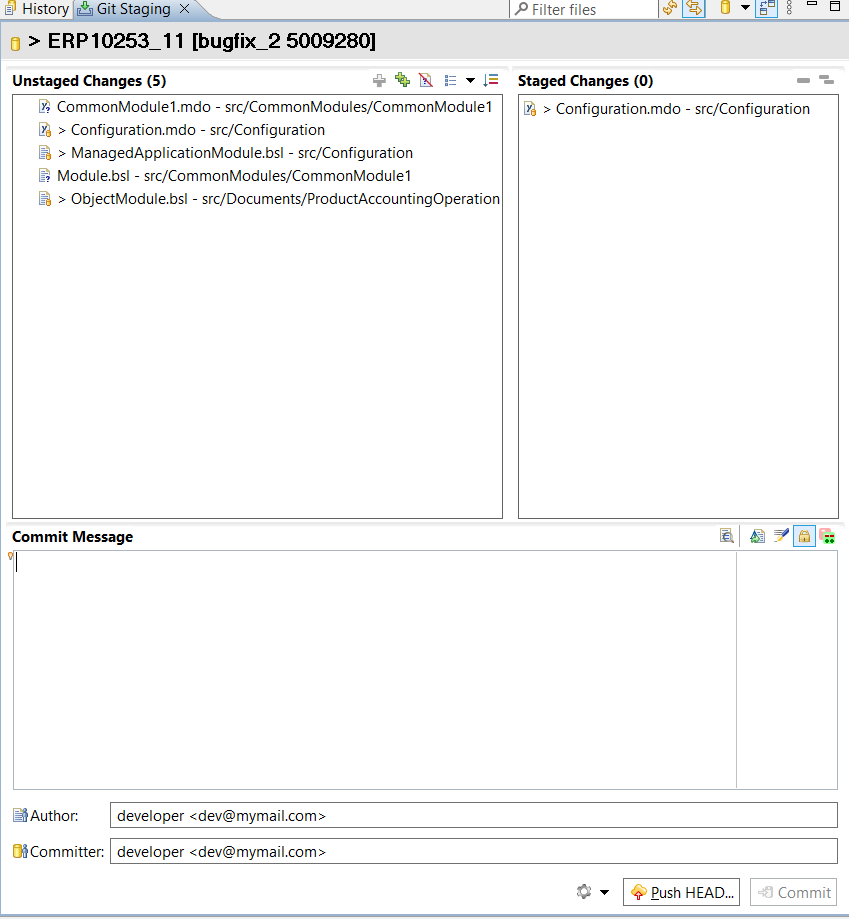
This panel is part of the standard Git perspective.
Open the Git Staging Panel
Click Window > Show View > Other… > Git > Git Staging.
Legend
The state of resources under version control is indicated by an icon in the lower right corner of the resource's icon:
- This represents an object (file) that is not yet under version control.
- This represents a new object (file) that has been added to the index and is ready for commit to the repository.
- This represents an object (file) that is already under version control. It remains unchanged in the working tree compared to the repository.
 A right-angle bracket next to an object (file) under version control indicates that the object has been modified in the working tree compared to the repository version.
- This represents a modified object (file) under version control. The changes have been added to the index and are ready for commit to the repository.
- This represents a partially indexed object (file). Some of its changes have been staged in the index but not yet committed, while other changes were made afterward and have not yet been staged.
- This represents a file that contains merge conflicts.
 This represents a file that was under version control but has been deleted from the file system.
- This represents a file that is ignored by the Git version control system.
- This represents a file marked as Assume Unchanged.
Configure Git Resource Indicators
Click Window > Preferences... > Version Control (Team) > Git > Label Decorations in the main menu. Learn More.
Field and Button Descriptions
- Unstaged Changes. This field displays changes that have not yet been staged.
- Staged Changes. This field displays changes that have been added to the index but have not yet been committed.
- Commit Message. A custom string that explains the changes for you and other developers.
- Author. The person who originally made the changes.
- Committer. The person who committed the author’s changes to the repository.
- Commit and Push.... Commits changes and immediately pushes them to the remote repository.
Unstaged Changes
Unstaged Changes: Command Bar
- (Add Selected Files to Index) adds the selected files from the Unstaged Changes section to the index.
- (Add All Files to Index) adds all files from the Unstaged Changes section to the index.
- (Hide Untracked Files) hides files that are not under version control.
 (Presentation) allows changing the way files are displayed, either as a list or a tree.
Unstaged Changes: Context Menu
- Open Working Tree Version opens the version of the file stored in the working tree in the editor.
- Compare with Index. Not used in 1C:Enterprise application development. compares the version of the selected file in the working tree with the version in the index.
- Add to Index adds the selected files from the Unstaged Changes section to the index.
- Replace with HEAD Revision replaces the selected files in the working tree with the latest commit.
- Assume Unchanged marks a file as Assume Unchanged.
- Ignore adds the file to
.gitignoreso that Git ignores it. - Delete removes the resource from the file system.
- Remove from Version Control removes the object from Git version control but leaves it in the working tree.
- Show in submenu:
- Explorer opens the resource in the system file explorer.
- Copy Path copies the relative path of this resource to the clipboard.
Staged Changes
Staged Changes: Command Bar
- (Remove Selected Files from Index) removes the selected files from the index.
- (Remove All Files from Index) removes all files from the index.
Staged Changes: Context Menu
- Open Working Tree Version opens the version of the file stored in the working tree in the editor.
- Compare with working tree. Not used in 1C:Enterprise application development. compares the file version in the index with the working tree.
- Compare with HEAD. Not used in 1C:Enterprise application development. compares the file version in the index with the latest commit.
- Remove from Index removes all files from the index.
- Show in submenu:
- Explorer opens the resource in the system file explorer.
- Copy Path copies the relative path of this resource to the clipboard.
Commit Message
Commit Message: Command Bar
 (Preview Commit Message). If the width of the input field Commit Message in edit mode is less than 72 characters, the commit message wraps within the visible part of the field. A click on this button will display the message with a width of 72 characters, showing how it will be recorded.
- (Amend, Edit Previous Commit) modifies the previous commit message.
- (Add Signed-off-by) adds the Signed-off-by: tag to the commit message, which is used by various project management systems.
 (Sign Commit). If selected, the commit will be signed with the PGP key specified in the Git parameter
 user.signingkey, see group development settings.- (Add Change-ID) adds the Change-ID: tag to the commit message, which is used for integration with Gerrit Code Review.
Customize Panel Appearance
Arrange File Fields Side by Side
By default, fields Staged Changes and Staged Changes are placed one below the other. To arrange them side by side, click ![]() (Show Menu) and then Arrange in Columns in the command bar.
(Show Menu) and then Arrange in Columns in the command bar.
Display Relative File Paths
By default, fields Staged Changes and Staged Changes first display the file name, followed by the directory it is in. To enable relative path display, click ![]() (Show Menu) and then clear Show File Names First in the command bar.
(Show Menu) and then clear Show File Names First in the command bar.
Display Files as a Tree
By default, fields Staged Changes and Staged Changes display files in a simple linear list. To switch to a tree view, click (Presentation) in the command bar of unstaged changes and select one of the following options:
- Tree
- Compact Tree
You can achieve the same result by clicking ![]() (Show Menu) and then Presentation in the command bar of Git Staging.
(Show Menu) and then Presentation in the command bar of Git Staging.
History Rewriting
Do not rewrite history if you have already pushed the branch to a remote repository, or looking at it from another perspective, do not push your branch to the remote repository until you are satisfied with it!
One of Git’s core features is that most of the development is done in a local repository. Because of this, you can modify your commit history as needed. You can amend, squash, split, delete, and reorder commits as required.
This means that instead of keeping the original commits, 1C:EDT will create new commits containing the same changes. As a result, you retain all necessary modifications while keeping a more understandable and clean commit history.
However, once you push a branch to a remote repository, all commits within it are no longer just "yours." They become "shared." Other developers may pull your branch, merge it with theirs, and incorporate your changes into their own work.
What happens when you rewrite commits in your branch and push it again to the remote repository? It will appear as though the original commits, which other developers were using, never existed. As a result, developers who have already pulled your branch will have to resolve this situation on their end, which may not be easy.
Therefore, avoid pushing your branch to the remote repository prematurely. Or, if you have already pushed your branch, do not rewrite its local history, as this can cause significant issues for other developers.
Of course, there are cases where rewriting commit history in a published branch is not harmful and can even be beneficial. For example, if it is purely an experimental branch or a branch meant for reviewing code (review branches).
Amend Last Commit
For instance, you committed changes and later realized you forgot to correct something related to the task. Or you forgot to include important details in the commit message.
Instead of fixing the omission with a new, separate commit, you can make the necessary changes and amend them to the last commit. As a result, a new commit will replace your previous commit.
-
Perform the forgotten changes (if you only need to amend the message, skip to step 4).
-
Open the Git Staging panel.
-
Click
(Add All Files to Index) of the Unstaged Changes field. -
Click
(Amend (Edit Previous Commit)) in the context menu of the Commit Message field.The message from the previous commit will appear in the field.
-
Edit the commit message.
-
Click Commit.
A new commit (with a new ID) will be created instead of the previous commit, containing both the previous and new changes along with the updated commit message.
Warning: Note that instead of modifying the previous commit, a new commit with a different ID is created. As a result, it will appear as if the original commit never existed. For this reason, do not amend a commit if you have already pushed it to the remote repository. Doing so will cause issues for developers who have already pulled your changes from the remote repository.
How to Undo the Last Commit Amendment
For example, you have a last commit, "third commit," to which you want to add some adjustments you forgot.
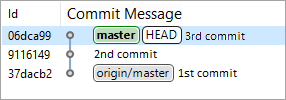
You make these adjustments, amend the last commit, update the commit message to "third commit + forgotten adjustments," and commit the changes.
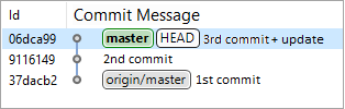
The previous commit is replaced by a new one with a new ID, new content, and a new commit message.
However, after launching the application and reviewing the result, you realize you rushed into amending the last commit. It would be better to revert everything to the state before adding the forgotten adjustments. But how do you do that if the old commit is already gone?
In reality, the old commit is not gone. it still exists in the object database. It is simply no longer visible in the history because it is not referenced by any branch.
To see this commit, you need to open the Git Reflog panel. It is included by default in the Git perspective, but you can also open it in any other perspective.
In this panel, ensure that the HEAD branch (or the current branch) is selected, and among the references, you will see the commit where the branch pointer was before the amendment. It will be the second-to-last commit.
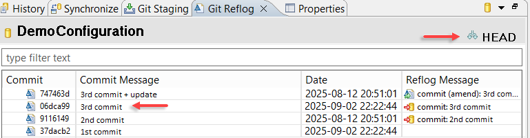
To undo the commit amendment, run a hard reset to this previous commit (Reset in the context menu, then Hard (HEAD, Index, and working tree)). Your branch will return to its previous state.
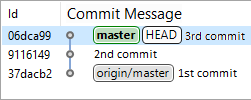
Edit a Commit Message (Reword)
For example, after committing changes, you realize you forgot to include something important in the commit message. You can amend the commit message by creating a new commit.
This applies not only to the latest commit but also to previous commits.
This can be done in the History panel:
-
Find the required commit in the list.
-
Click Modify, then Edit Message in its context menu.
-
Edit the commit message.
-
Click Edit Message.
A new commit will be created in place of the previous one. If it is not the last commit, then all subsequent commits will also be recreated.
Warning: Note that instead of modifying the existing commit and its successors, new commits with new IDs will be created. As a result, it will appear as if the original commits never existed. For this reason, do not edit a commit message if you have already pushed it to the remote repository. Doing so will cause issues for developers who have already pulled your changes from the remote repository.
Fastpath: If the result of the commit message change does not satisfy you, you can revert everything to its previous state, just like in a standard rebase. See section How to Undo a Rebase for details.
Edit a Previous Commit (Edit)
After committing the latest changes, you can amend the commit to add modifications you forgot.
Similarly, you can edit an earlier commit, but a different command is used, which results in a different operation: interactive rebase.
You can amend a previous commit in the History panel:
-
Find the required commit in the list.
-
Click Modify, then Edit in its context menu.
-
1C:EDT will open the Interactive Rebase panel. The selected commit will have the action Edit, while the following commits will have the action Pick.
-
Make the changes you want to include in this commit.
-
In the Git Staging panel, click
(Add All Files to Index) in the context menu of the field Unstaged Changes. -
Edit the commit message.
-
Click Commit.
-
Click Continue in the Interactive Rebase panel or in the Git Staging panel.
Warning: Note that instead of modifying the existing commit and its successors, new commits with new IDs will be created. As a result, it will appear as if the original commits never existed. Therefore, do not edit a previous commit if you have already pushed it to a remote repository. Doing so will cause issues for developers who have already pulled your changes from the remote repository.
Fastpath: If you are not satisfied with the result of editing a previous commit, you can revert to the previous state, just as with a standard rebase. See section How to Undo a Rebase for details.
Squashing Commits
Before merging your branch into the project, you may want to hide commits that were only relevant during development. You can merge minor commits into significant ones or even combine all commits into a single one.
Use interactive rebase for this:
-
Check out the branch you want to modify. For example, feature.
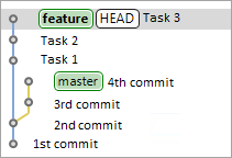
-
In the History panel, select the parent of this branch.
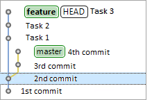
-
Click Interactive Rebase in the context menu of this commit. To specify the operations to be applied to commits, 1C:EDT will open the Interactive Rebase panel.
-
For all commits except the first, select the action Squash.
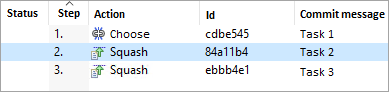
-
Click Start to begin interactive rebase.
-
1C:EDT will create a new commit instead of the previous ones and open a dialog displaying the commit messages of all merged commits.
-
Edit the new commit message.
-
Click Edit Message.
As a result, instead of the previous three commits, a single new commit will be created containing all their changes.
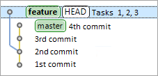
Warning: Interactive rebase rewrites commit history. Therefore, do not perform an interactive rebase if you have already pushed your branch to a remote repository. Your colleagues may have already used the changes you published in their own development. Your interactive rebase will also force them to overwrite and modify their own changes. The only exceptions are branches intended exclusively for experiments or review purposes.
Fastpath: If you are not satisfied with the result of merging commits, you can revert to the previous state, just as with a standard rebase. See section How to Undo a Rebase for details.
History
History Panel
The History panel displays repository resources, focusing on commits. It allows you to view resource change history, compare different versions of resources, search for specific commits using various criteria, extract commits, and create branches and tags.
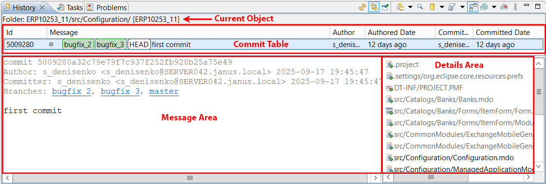
This panel is included in the standard perspectives of Git and Synchronize.
Opening the History Panel
You can open this panel in several ways:
- In the Navigator panel, right-click the project and select Version Control (Team) > Show History from the context menu.
- In the Git Repositories or Project Structure panel, right-click and select Show in > History from the context menu.
- In the main menu, click Window > Show View > Other... > Version Control (Team) > History.
At the top of the panel, there is a Commit Table. Commits are listed in reverse chronological order, with the most recent commit at the top.
The second column in the table contains the Commit Graph. This graph shows the relationships between parent and child commits in the list. Every commit has at least one parent, except for the very first commit.
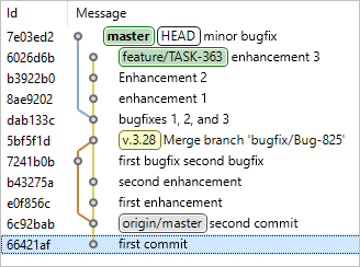
Additionally, the graph shows branching points, representing new branch creation, and merges, representing branch merging.
To the left of the commit table, the Current Object is displayed, showing the commits that are listed. This can be a project, folder, or file. The repository name appears in square brackets after the object name.
At the bottom of the panel, there are the Message Area and the Details Area. The details area displays a list of files modified by the selected commit in the table. If a merge commit is selected, only a subset of modified files may be displayed, depending on the state of the toggle  (First Parent Only).
The message area shows the commit message and other information related to the commit selected in the table. Additionally, if you select a file in the details area, the message area in 1C:EDT will display the changes made to that file compared to its previous state.
Find Commits
Trouble: The panel displays only part of the entire history if the history is very long. As you scroll through the commit list, history loads dynamically. The search runs only among the commits that have already been loaded. If you are looking for an older commit, scroll the history to approximately the date of the commit and then perform the search.
To start searching for commits, click  (Show Find Toolbar) in the command bar. 1C:EDT will display a search field in the command bar along with several additional buttons.
-
 (Go to Next Commit Matching Search Criteria)
 -
 (Go to Previous Commit Matching Search Criteria)
 -
 (Change to)
The search runs automatically as you type in the search field. You can enter any substring that is part of the desired word.
Matching commits appear in bold. If no matching commits are found, the search field is highlighted in red.
Using buttons 1 and 2 in the command bar, you can move forward and backward through the found commits.
By default, 1C:EDT searches all possible commit components. If this search returns too many results, you can narrow the search scope. To do this, click button 3 or open its dropdown list and select one of the components to search in.
-
Comments searches within commit messages.
-
Author searches within author details, including name and email address.
-
Id searches within commit identifiers.
-
Committer searches within committer details, including name and email address.
-
Branch/Tag searches within branch and tag names.
By default, the search ignores case sensitivity.If case sensitivity is important, uncheck Ignore Case in the dropdown menu of button 3.
Tip: You can also search for commits using the main menu command Search > Git... or ![]() (Search) Search in Git in the Main Window Command Bar.
(Search) Search in Git in the Main Window Command Bar.
Filter Commits
Filtering commits can be useful when working with the Navigator panel or the Git Repositories panel. To do this, the History panel must be linked to the editor (Link with Editor).
For example, as you navigate through the Navigator panel, the History panel displays different commit sets. To specify which commit area to focus on, use the button (Change the File Scope for the History) in the command bar. Clicking it or opening its dropdown list allows you to choose one of the following areas.
-
All Repository Changes displays commits from the repository where the selected project is located.
-
All Project Changes displays changes for the selected project. For example, only extension commits if the main configuration and the extension are in the same repository.
-
All Changes in the Parent Directory displays changes in objects at the same hierarchy level. For example, commits of catalogs.
-
All Changes in the Resource displays changes in the selected object. For example, commits of a specific catalog or its form.
Show All Branches
By default, the History panel displays only commits from the current branch (HEAD). However, when performing merge operations, it can be useful to see other branches as well. To specify which branches’ commits should be displayed, use button (Change Which Commits to Show) in the command bar. Clicking it or opening its dropdown list allows you to select one of the templates.
-
HEAD: the current branch.
-
refs/**/${git_branch}: the current local branch and its remote tracking branch.
-
refs/heads/**: local branches.
-
refs/remotes/**: remote tracking branches.
-
refs/tags/**: tags.
If you want to configure additional templates for displaying branches, click Ref Filters... in the dropdown list of button (Change Which Commits to Show).
References
Refs is a short name for Git references. These include:
- Branches
- Remote tracking branches
- Tags
All references are identified by a path starting with refs/.
- Local branches start with refs/heads/.
- Remote tracking branches start with refs/remotes/.
- Tags start with refs/tags/.
Reference names can be shortened if the shortened form is unique. Example:
- master can be used instead of refs/heads/master.
- origin/master can be used instead of refs/remotes/origin/master.
- v1.0.1 can be used instead of refs/tags/v1.0.1.
Some reserved reference names are used in specific scenarios.
- HEAD points to the currently checked-out commit.
- FETCH_HEAD points to the result of the last fetch operation.
- ORIG_HEAD points to the commit that was checked out before a merge or rebase operation.
The full list of reserved names can be viewed here.
Hide Merged Branch Commits
By default, the History panel shows commits from the branch you are viewing, along with commits from merged branches. As a result, you see a branching scheme that can be quite complex.
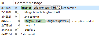
If commits from other branches are not relevant to you at the moment, click (First Parent Only) in the command bar. This will display only the commits made directly in the branch you are viewing.
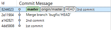
Customize Panel Appearance
Column Selection in the Table
- Click (Show Menu), then Table in the command bar.
- Check the boxes for the columns you want to display.
Commit Details Display
By default, the lower section of the 1C:EDT panel shows the message area and the details area. You can hide the message area or both areas.
To display only the details area:
- Click (Show Menu), then Show in the command bar.
- Uncheck Revision Comment.
- Ensure that Revision Details is checked.
To hide both areas:
- Click (Show Menu), then Show in the command bar.
- Uncheck Revision Details.
- The state of Revision Comment does not matter in this case.
Absolute Dates in Commits
By default, the panel displays the relative commit date, such as 4 days ago. To enable the display of absolute dates, for example 2023-10-16, uncheck ![]() (Show Menu) Show Relative Dates in the command bar.
(Show Menu) Show Relative Dates in the command bar.
Author and Committer Email
To display email addresses next to the author and committer names in the commit table, click ![]() (Show Menu) Show E-mail Addresses in the command bar.
(Show Menu) Show E-mail Addresses in the command bar.
Branching
A branch is a named reference to a commit. For example, the master branch or the origin/master branch.
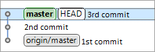
Branches allow multiple tasks to be run in parallel within a single repository. Each branch contains the entire project, but the state of the project varies between branches. For instance, the master branch contains a stable version of the project that is ready for use. The release/1.5.4 branch contains the next new version of the project being prepared for release. Meanwhile, the develop branch is where future functionality is being developed for versions 1.5.5 and beyond.
Git makes it easy to create new branches based on existing ones and then merge changes from different branches by integrating them.
There are two types of branches: local branches and remote tracking branches, each serving a different purpose.
Local branches (such as master in the illustration) help keep track of commits made in the local repository. Each time a change is committed, a new commit is added to the local repository. A local branch always points to the latest commit. When a new commit is created, the branch pointer automatically moves forward.
Starting from any commit in your local branch, you can create a new branch and develop a new feature Independently and in parallel with the main branch. Once your work is complete, you can merge all your changes from this branch into the main one.
Remote tracking branches are useful when working with a remote repository. These branches typically have composite names, such as origin/master in the illustration.
A remote tracking branch always corresponds to a specific local branch in the remote repository. In the illustration, your remote tracking branch origin/master corresponds to the local master branch in the remote repository origin. Git ensures that this correspondence remains up to date whenever you fetch or push changes to the remote repository.
This allows you to use the origin/master branch to merge its changes into your local branch or push your local branch to the remote repository.
Remote tracking branches are created automatically when cloning a repository. Additionally, you can manually configure the correspondence between your local branch and a specific branch in a remote repository.
Creating a New Branch
The main way to create new branches in 1C:EDT includes additional features such as creating a new infobase for the branch and using snapshots when switching branches. To learn how to do this, read here.
Additionally, 1C:EDT allows you to create new branches using standard Git tools without considering the specifics of 1C:Enterprise development. This can be done in several ways:
-
In the History panel, right-click the commit from which you want to create a new branch and select Create Branch....
-
In the Git Repositories panel, right-click the branch or tag and select Create Branch....
Field Descriptions
-
Source is the current branch checked out in the working tree. If necessary, you can select a different source branch by clicking Select. If you choose a remote tracking branch, 1C:EDT will suggest creating a new local branch with the same name.
-
Branch Name is the name of the new branch.
-
Configure Upstream for Push and Fetch. Select this checkbox if you want to specify the upstream configuration and the method that will be used to run the Pull operation (retrieving changes from the origin repository and merging them with the current branch).
-
Rebase fetches changes from the upstream repository and updates the remote tracking branch. Then, the commits from the local branch are rebased onto the updated remote tracking branch. Learn more about rebasing here.
-
Rebase While Preserving Merge Commits performs the rebase like the first option but keeps merge commits intact.
-
Interactive Rebase lets you rebase local branch commits onto the updated remote tracking branch in an interactive mode. Learn more about interactive rebasing here.
-
Merge Changes will be fetched from the upstream repository, and the remote tracking branch will be updated. Then, it will be merged into the current branch. This is the standard method used in most cases.
-
-
Check Out a New Branch If this option is enabled, the newly created branch will be checked out immediately so that you can make changes to it. Otherwise, only the branch will be created, and the current branch will remain unchanged.
Switch to Another Branch (Checkout)
You can switch the local repository to another branch in several ways.
-
In the Navigator panel, right-click the project and select Version Control (Team) > Switch To. If the desired branch is not visible, click Other....
-
In the History panel, right-click a commit and select Check Out.
-
In the Git Repositories panel, double-click a branch or right-click it and select Check Out.
If you attempt to switch to a remote tracking branch that does not exist locally, 1C:EDT will ask how you want to check it out.
-
Check Out as New Local Branch This creates a new local branch and checks out the remote tracking branch for further modifications.
-
Check Out Commit This does not create a local branch but checks out only the commit for viewing. In this case, the local repository enters a Detached HEAD state.
Wait while the branches switch. You can track the process in the lower-right corner of the screen or in the Status panel.
Detached HEAD
A Detached HEAD occurs when the local repository contains the project at a specific commit, but no local branch is checked out.
For example, suppose the master branch is currently checked out.
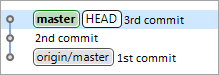
If you check out the second commit, the local repository will enter a Detached HEAD state, meaning no branch corresponds to it.
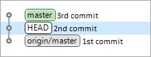
In this state, you can view everything in the working tree. For example, you might check how the application looked at the time of the second commit.
However, you should not modify the project while in this state because you will not be able to commit your changes. They will not belong to any branch.
If you need to make changes, you should either create a new branch while in this state or first check out an existing branch.
Rename Branch
You can rename a branch in several ways.
-
In the Navigator panel, right-click the project and select Version Control (Team) > Advanced Features > > Rename Branch...from the context menu.
-
In the History panel, right-click a commit and select Rename Branch....
-
In the Git Repositories panel, right-click a branch and select Rename Branch....
Deleting a Branch
You can delete a branch in several ways.
-
In the History panel, right-click a commit and select Delete Branch....
-
In the Git Repositories panel, right-click a branch and select Delete Branch....
Switching Branches Using Snapshots
When switching from one branch to another, 1C:EDT recalculates secondary data that will be used for a more convenient development process. Secondary data includes:
-
Internal representation of configuration objects
-
Various configuration element indexes
-
Error and warning information from the configuration
-
Type information for elements in the 1C:Enterprise language
-
Other data that facilitate development
For large configurations, the size of secondary data is around 3 GB due to the size of configurations. For example, 1C:ERP has the following characteristics:
-
The source code occupies approximately 5 GB.
-
19,000 program module files with a total size of 1 GB.
-
The largest modules contain more than 50,000 lines of code.
-
8,000 screen forms.
-
17,000 configuration objects.
-
1,600 roles.
-
800 reports.
Calculating such a large amount of secondary data takes time, making branch switching slow.
To solve this issue, we developed a branch-switching mechanism that uses snapshots. Its main goal is to significantly speed up repository branch switching for large configurations in 1C:EDT.
For each repository branch where you enable this mechanism, a snapshot is saved. This is an archive containing all internal project data. When switching back to the same branch, secondary data is restored from the snapshot. This prevents unnecessary recalculations of secondary data in 1C:EDT and speeds up your workflow.
Snapshots are linked to commits, allowing you to track their relevance. If the branch linked to a snapshot changes (a new commit is added or the branch is reset to an earlier commit), the snapshot becomes outdated and will not be used.
By default, 1C:EDT enables snapshots for the branches master, main, and develop, as well as for branch types in the Team Development parameter group that create a new infobase. You can manually configure which branches should have snapshots. This can be configured for the entire workspace or for specific projects.
Additionally, you can choose to save or discard snapshots when switching branches. 1C:EDT displays a dialog for saving or restoring metadata snapshots. If you do not need these dialogs regularly, you can disable them. If you need them later, you can enable them in the 1C:EDT preferences.
Snapshots are stored in the workspace, individually for each project. From the project settings, you can open the directory containing snapshots.
Configuring Snapshot Usage
You can manually configure which branches should have snapshots. This setting can be applied to the entire workspace or specific projects.
Configuring the Workspace
In the main menu of the main window, click Window > Preferences > V8 > Metadata Snapshots.
This will open the Metadata Snapshots parameter group for the workspace.
Configuring a Specific Project
In the Navigator panel, click Properties > V8 > Metadata Snapshots in the project’s context menu.
This will open the Metadata Snapshots parameter group for the project.
Disabling Snapshot Save and Restore Dialogs
To disable the save and restore snapshot dialogs, follow these steps:
- When any of these dialogs appear, check Always agree.
Or:
-
Open the workspace snapshot settings.
-
Uncheck Warn before creating and restoring snapshots.
Enabling Snapshot Save and Restore Dialogs
To enable the save and restore snapshot dialogs, follow these steps:
-
Open the workspace snapshot settings.
-
Check Warn before creating and restoring snapshots.
Opening the Snapshot Directory
-
Open the project’s snapshot settings.
-
Click Open Metadata Snapshot Folder.
Creating a New Branch
You can create a new branch in several ways:
- In the Navigator panel, right-click the project and select Version Control (Team) > Create New Branch... from the context menu.
- In the Development panel:
- click Version Control (Team) > Create New Branch... in the project’s context menu
- or click Create New Branch... in the task’s context menu
A new local repository branch will be created from the project's current branch. If you want to use a different parent branch, you can select it during the branch creation process.
If the current Git branch has upstream configuration, it will be applied to the new branch.
If you select Create a New Infobase with a Copy of Data from the Main Branch as the infobase for development, the new infobase will retain the same access settings as the original infobase.
Field Descriptions
- Branch Type. This is one of the branch types configured in 1C:EDT. The following standard branch types exist:
- Bugfix. These branches are used to fix bugs. One or more related bugs are fixed in a single bugfix branch.
- Feature. These branches are used for developing new functionality. Each new feature, a new technical project, is developed in its own feature branch.
- Release. These branches are used to prepare a version for release. New functionality is not added to a release branch. Only bug fixes, documentation generation, and other release-related tasks are included.
- Custom. These are arbitrary branches intended for tasks that do not fit into the predefined categories.
You can modify the standard branch types or add custom branch types. To do this, click Preferences... next to the Branch Type field.
- Source. This is the parent Git branch from which the new branch will be created. By default, the parent branch is the one the project is currently switched to. However, you can select a different repository branch as the parent. To do this, click Select... next to the branch name.
- Branch Name. This is the prefix and name of the new Git branch.
Deleting a Branch
You can delete a branch in several ways.
-
In the Navigator panel, right-click the project and select Version Control (Team) Delete Branch... from the context menu.
-
In the Development panel:
-
Click Delete Branch... in the task or branch context menu.
Or
-
click Version Control (Team) Delete Branch... in the project’s context menu.
-
The branch deletion wizard may have different appearances depending on the context.
If the command context already knows which branch should be deleted, the wizard will be simplified and will offer an additional option to delete the infobase linked to that branch.
If the local branch has upstream configuration, the wizard will also suggest deleting the respective remote branch.
If the command context does not specify the branch to delete, the wizard will display all project repository branches linked to infobases. Once you select a branch, you can delete it, delete its associated infobase, or remove the remote-tracking branch if one exists.
Creating a New Branch to Fix an Issue in an External Configuration
One use case for branching is when a client sends their infobase where an issue is reproducible. To fix this issue, you can create a new Git branch that will use the client's provided data.
Warning: Keep in mind that the client's configuration and the one in the project's current branch must be identical. Otherwise, when launching or debugging, 1C:EDT will attempt to load the configuration from the current project branch into the infobase, causing a restructuring of the client's infobase. Loading a configuration from an infobase into a new Git branch is not possible.
To follow this process:
-
In the Navigator panel, right-click the project and select Version Control (Team) Create New Branch... from the context menu.
-
In the Development Infobase field, select Create a New Infobase and Load Contents from a .dt File.
-
In the Dump File field, select the .dt file provided by the client.
-
Click Finish.
1C:EDT will create a new infobase, load the specified export file into it, and link this new infobase to a new Git branch.
Metadata Snapshot Save Dialog
This dialog allows you to skip snapshot creation when switching branches.
Clicking OK will execute the listed snapshot operations.
Clicking Cancel will switch branches without using snapshots.
If you always want to use snapshots, check Always agree. This will prevent the dialog from appearing in the future, and snapshot operations will always be run.
To re-enable this dialog, open the snapshot settings for the workspace.
Metadata Snapshot Restore Dialog
This dialog allows you to cancel creating a snapshot and restoring from a snapshot when switching to another branch.
Clicking OK will execute the listed snapshot operations.
Clicking Cancel will switch branches without using snapshots.
If you always want to use snapshots, check Always agree. This will prevent the dialog from appearing in the future, and snapshot operations will always be run.
To re-enable this dialog, follow these steps.
Team Development parameter group
The Team Development parameter group allows you to configure the default settings that 1C:EDT applies when creating Git branches linked to infobases.
Open the Team Development parameter group
You can open the Team Development parameter group in several ways:
- In the main menu, click Window > Preferences... > V8 > Team Development.
- When creating a new branch, click Preferences... next to the Branch Type field.
Field Descriptions
- Branch Type Management. A list of standard branch types that will be available for selection when creating a new branch (more details).
- Add.... Adds a new type to the list of standard branches. The name can be arbitrary, allowing you to distinguish one branch type from another. You can also specify a prefix for the type. This prefix will be included in the name of each Git branch created for this type.
- Copy.... Creates a new branch type in the list by copying the selected type.
- Edit.... Modifies the name and prefix of the branch type.
- Delete.... Removes a branch type from the list.
The fields below contain values applied to the branch type selected in the Branch Type Management list.
- Development Infobase. This is one of the ways to link a new branch to an infobase:
- Use the same infobase as in the main branch. The new Git branch will be linked to the infobase assigned to the branch selected in the Source File field.
- Create a new infobase with a copy of the data from the main branch. A new standard-type infobase will be created, containing a copy of the infobase linked to the branch selected in the Source File field. Additionally, the same access settings as the source infobase will be applied to the new infobase. The new infobase will be linked to the new Git branch.
- Create a new infobase and load content from a .dt file. A new standard-type infobase will be created, containing the infobase from the file specified in the Dump File field. The new infobase will be linked to the new Git branch.
The configuration of the current project branch must match the configuration in the .dt file. Otherwise, when running or debugging, 1C:EDT will attempt to load the configuration from the current project branch into the infobase, which will lead to restructuring of the infobase received from the customer.
- Create a new infobase and load content from a database file (1Cv8.1CD). A new standard-type database will be created, containing the infobase from the file specified in the Database File field. The new infobase will be linked to the new Git branch.
- Select an infobase from the list. The new Git branch will be linked to the selected infobase. The configuration of the current project branch must match the configuration in the selected infobase. Otherwise, when running or debugging, 1C:EDT will attempt to load the configuration from the current project branch into the infobase, leading to restructuring of the selected infobase. It is not possible to load the configuration from the infobase into the new Git branch.
- Do not use an infobase. A new Git branch will be created that is not linked to any infobase.
- Create a new empty infobase. A new standard-type infobase will be created without a configuration. The new infobase will be linked to the new Git branch.
If the standard infobase type, file-based or client-server, does not meet your needs, it can be changed in the next steps of the wizard. Some parameters, such as the group where the infobase is added, the path to the file-based infobase, or cluster server settings, can also be adjusted.
If you want to define a different standard infobase type and other default parameters that should always be used when creating new branches, click Preferences... next to the Branch Type field (learn more).
- Specify the Infobase Placement Type. The type of the new infobase, file-based or client-server, that will be created by default if one of the scenarios is used where a new Git branch is linked to a new infobase.
- Infobase Creation Settings. Settings that will be used in scenarios where a new infobase is created:
- Group. The name of the group in the Infobases panel where the new infobase will be placed.
- Language (Country). Regional settings of the infobase. Selected from the suggested list, these define the set of regional settings, such as number and date formats or sorting order, that will be used when interacting with the infobase.
- File-Based Infobase Creation Settings:
- Parent Directory. The folder where directories for infobases linked to this branch type will be created.
Project Parameter Group: Metadata Snapshots
The Metadata Snapshots parameter group allows you to select branches within a specific project for which 1C:EDT will save secondary data snapshots and restore data from snapshots when switching back to these branches.
To enable branch-specific settings for this project, uncheck Use workspace settings.
Open Project Settings: Metadata Snapshots
In the Navigator panel, click Properties > V8 > Metadata Snapshots in the project's context menu.
Field Descriptions
- Use Metadata Snapshots. Enables or disables snapshot usage for this project. If unchecked, all saved snapshots for this project will be deleted.
- Use Workspace Settings. Uncheck this option to enable branch-specific settings for this project.
- Show Workspace Settings.... Opens the Metadata Snapshots parameter group.
- Add, Delete, and Edit. Modify the branch list.
- Open Metadata Snapshot Folder. Opens the directory where snapshots are stored.
Workspace Parameter Group: Metadata Snapshots
The Metadata Snapshots parameter group allows you to select branches for which 1C:EDT will save secondary data snapshots and restore data from snapshots when switching back to these branches.
Open Workspace Settings: Metadata Snapshots
Click Window > Preferences... > V8 > Metadata Snapshots in the main menu.
Field Descriptions
- Warn before creating and restoring snapshots. Determines whether dialogs for saving and restoring snapshots will appear when switching branches.
- Add, Delete, and Edit. Modify the branch list.
Merge
Merging involves incorporating all changes from another branch into the current branch, starting from the point where their histories diverged. The most convenient way to merge is from the History panel since it displays the full history of your repository.
Merge This Branch
To merge Branch B into the current Branch A, first locate Branch B in 1C:EDT and then initiate the merge. This can be done in different panels:
-
In the History panel:
-
In the Navigator panel:
-
Click Version Control (Team) > Merge... in the project context menu.
-
Select Branch B or the tag you want to merge.
-
-
In the Git Repositories panel:
-
Find Branch B or the tag you want to merge.
-
Click Merge in the context menu of this branch.
-
Merge Options
1C:EDT will prompt you to configure merge options. If the default options suit your needs, you can leave them as is and simply click Merge. Merge Options:
-
Merge Options
-
Commit (record the result) Merges changes and creates a merge commit.
-
Do not commit (prepare the merge but do not commit it) Merges changes and prepares a merge commit without finalizing it.
-
Squash Commits (merge in the working tree without creating a merge commit) Applies the changes and prepares a regular commit instead of a merge commit.
-
-
Fast-Forward Options Specifies what to do when the result of fetching and merging allows fast-forwarding:
-
Update only the branch pointer if fast-forwarding is possible Updates only the pointer of the current branch.
-
Create a merge commit even if fast-forwarding is possible Creates a merge commit and sets the current branch pointer to it.
-
Cancel if fast-forwarding is not possible Aborts the merge if it cannot result in a fast-forward.
-
-
Matching Strategy This determines how objects in the merged and current configurations are matched. This method is used when there are conflicting changes that need to be resolved manually in the Compare and Merge Configurations Editor:
-
By UUID Matches objects by their internal configuration object identifier.
-
By Name Matches objects by their configuration object name.
-
By UUID, then by Name First, it searches for a configuration object with the same internal identifier. If none is found, it searches for a configuration object with the same name.
-
-
Compare Modules Considering Structure If this option is selected, 1C:Enterprise language modules are compared based on individual methods within the module. Otherwise, modules are compared as a single text block.
-
Open the Comparison and Merge Editor (even if there are no potential issues) Selecting this checkbox forces the Compare and Merge Configurations Editor to open even when there are no conflicting changes. This can be useful when you want to visually review changes being made to the current configuration.
-
External Merge Settings This specifies the path to the file containing previously saved configuration merge settings from the Compare and Merge Configurations Editor.
Merge Result
After clicking Merge, one of the following situations may occur:
-
Already-up-to-date The current local branch (e.g., master) points to a commit for which the merged branch or tag (e.g., feature) is an ancestor. There are no updates, and no changes have occurred.
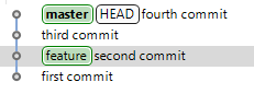
-
Fast-forward The current local branch (e.g., master) points to a commit that is an ancestor of the merged branch or tag (e.g., feature). In this case, the local branch is moved to point to the merged branch or tag. This new HEAD is then checked out into the working tree.
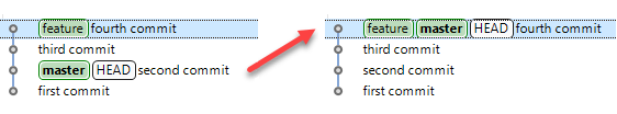
-
If none of the above conditions apply, 1C:EDT starts the merge process. A merge can have two outcomes:
-
Merged The branches being merged do not have conflicting changes. 1C:EDT creates a merge commit and moves the current branch to point to the merge commit.
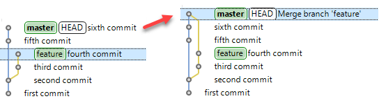
-
Conflicting The branches being merged contain conflicting changes. 1C:EDT opens the Compare and Merge Configurations Editor so that you can manually resolve these conflicts. The Compare and Merge Configurations Editor opens when all of the following conditions are met:
-
A real comparison or merge of projects from the repository runs, and there are differences between the merged branches.
-
During comparison, potential issues (including conflicting changes) are detected, or the Open Comparison/Merge Editor (even if there are no potential issues) option is selected. In the following cases, comparison or merging does not occur, and the editor does not open:
-
If a fast-forward is possible and any fast-forward option other than Create a merge commit even if fast-forwarding is possible is selected.
-
If the project name or its location relative to the repository root does not match in the merged branches. If a merge results in conflicts, you can abort it by performing a hard reset to the current branch. This can be done both before resolving conflicts (in the Conflicting state) and after (in the Merged state).
-
Merge Arbitrary Branch
To merge Branch B into the current Branch A, first initiate the merge process and then select Branch B. This can be done in different panels:
-
In the Navigator panel, click Version Control (Team) > Merge... in the project context menu and choose the branch or tag you want to merge into the current one.
-
In the Git Repositories panel, click Merge... in the current branch's context menu and select the branch or tag you want to merge into the current one.
1C:EDT will prompt you to configure merge options. If the default options suit your needs, you can leave them as is and simply click Merge. Merge Options:
-
Merge Options
-
Commit (record the result) Merges changes and creates a merge commit.
-
Do not commit (prepare the merge but do not commit it) Merges changes and prepares a merge commit without finalizing it.
-
Squash Commits (merge in the working tree without creating a merge commit) Applies the changes and prepares a regular commit instead of a merge commit.
-
-
Fast-Forward Options Specifies what to do when the result of fetching and merging allows fast-forwarding:
-
Update only the branch pointer if fast-forwarding is possible Updates only the pointer of the current branch.
-
Create a merge commit even if fast-forwarding is possible Creates a merge commit and sets the current branch pointer to it.
-
Cancel if fast-forwarding is not possible Aborts the merge if it cannot result in a fast-forward.
-
-
Matching Strategy This determines how objects in the merged and current configurations are matched. This method is used when there are conflicting changes that need to be resolved manually in the Compare and Merge Configurations Editor:
-
By UUID Matches objects by their internal configuration object identifier.
-
By Name Matches objects by their configuration object name.
-
By UUID, then by Name First, it searches for a configuration object with the same internal identifier. If none is found, it searches for a configuration object with the same name.
-
-
Compare Modules Considering Structure If this option is selected, 1C:Enterprise language modules are compared based on individual methods within the module. Otherwise, modules are compared as a single text block.
-
Open the Comparison and Merge Editor (even if there are no potential issues) Selecting this checkbox forces the Compare and Merge Configurations Editor to open even when there are no conflicting changes. This can be useful when you want to visually review changes being made to the current configuration.
-
External Merge Settings This specifies the path to the file containing previously saved configuration merge settings from the Compare and Merge Configurations Editor.
Merge Result
After clicking Merge, one of the following situations may occur:
-
Already-up-to-date The current local branch (e.g., master) points to a commit for which the merged branch or tag (e.g., feature) is an ancestor. There are no updates, and no changes have occurred.
-
Fast-forward The current local branch (e.g., master) points to a commit that is an ancestor of the merged branch or tag (e.g., feature). In this case, the local branch is moved to point to the merged branch or tag. This new HEAD is then checked out into the working tree.
-
If none of the above conditions apply, 1C:EDT starts the merge process. A merge can have two outcomes:
-
Merged The branches being merged do not have conflicting changes. 1C:EDT creates a merge commit and moves the current branch to point to the merge commit.
-
Conflicting The branches being merged contain conflicting changes. 1C:EDT opens the Compare and Merge Configurations Editor so that you can manually resolve these conflicts. The Compare and Merge Configurations Editor opens when all of the following conditions are met:
-
A real comparison or merge of projects from the repository runs, and there are differences between the merged branches.
-
During comparison, potential issues (including conflicting changes) are detected, or the Open Comparison/Merge Editor (even if there are no potential issues) option is selected. In the following cases, comparison or merging does not occur, and the editor does not open:
-
If a fast-forward is possible and any fast-forward option other than Create a merge commit even if fast-forwarding is possible is selected.
-
If the project name or its location relative to the repository root does not match in the merged branches. If a merge results in conflicts, you can abort it by performing a hard reset to the current branch. This can be done both before resolving conflicts (in the Conflicting state) and after (in the Merged state).
-
Abort Merge
If a merge results in conflicts, you can abort it by performing a hard reset to the current branch. This can be done both before resolving conflicts (in the Conflicting state) and after (in the Merged state).
Revert a Merge Commit
For example, you committed a merge and later realized that it does not suit your needs. You can create another commit that rolls back all the changes made by that merge commit.
Cherry Pick
The Cherry Pick operation applies a copy of the selected commit on top of the current commit. This method allows you to transfer individual commits from other branches into the current branch.
To perform Cherry Pick, open the History panel and click Cherry-Pick... in the context menu of the commit you want to include in the current branch.
Field Descriptions
-
Matching Strategy This determines how objects in the merged and current configurations are matched. This method is used when there are conflicting changes that need to be resolved manually in the Compare and Merge Configurations Editor:
-
By UUID Matches objects by their internal configuration object identifier.
-
By Name Matches objects by their configuration object name.
-
By UUID, then by Name First, it searches for a configuration object with the same internal identifier. If none is found, it searches for a configuration object with the same name.
-
-
Compare Modules Considering Structure If this option is selected, 1C:Enterprise language modules are compared based on individual methods within the module. Otherwise, modules are compared as a single text block.
-
Open the Comparison and Merge Editor (even if there are no potential issues) Selecting this checkbox forces the Compare and Merge Configurations Editor to open even when there are no conflicting changes. This can be useful when you want to visually review changes being made to the current configuration.
-
External Merge Settings This specifies the path to the file containing previously saved configuration merge settings from the Compare and Merge Configurations Editor.
Rebasing
What Is Rebasing
Rebasing applies a selected sequence of commits on top of a specified commit.
This is typically needed in the following scenario. You are developing in the feature branch with tasks Task 1, Task 2, and Task 3, which was created from the master branch. While you are working, new changes appear in the master branch, such as contributions from other developers (Third Commit, Fourth Commit). These changes need to be included in the feature branch since they are required for your development.
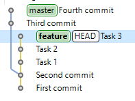
To achieve this, you can rebase the feature branch onto the master branch. Technically, this means that commits in the feature branch after it diverged from master (Task 1,Task 2, Task 3) will be reapplied one by one using the Cherry-Pick operation on top of the master branch.
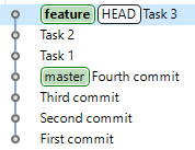
The original Task 1, Task 2, and Task 3 commits are not lost or modified. Instead, a new sequence of commits, Task 1_, Task 2_, and Task 3_, is created, containing the same changes and commit messages as the original commits, but with different commit identifiers. The old commits Task 1, Task 2, and Task 3 still exist in the object database but are no longer visible because they are not referenced by any branch. The new commits Task 1_, Task 2_, and Task 3_ differ from the old ones because they now also include the changes from Third Commit and Fourth Commit.
Rebase the Current Branch onto Another Branch
You can Rebase the current branch onto another branch in several ways.
-
In the History panel:
-
Check out the branch you want to rebase.
-
Select the commit to which you want to rebase the checked-out branch.
-
Click Rebase HEAD on in the context menu of this commit.
-
-
In the Navigator panel:
-
Right-click the project and select Version Control (Team) then Rebase....
-
Choose the branch onto which the current branch should be rebased and click Rebase.
-
-
In the Git Repositories panel, select the branch onto which the current branch should be rebased and click Rebase.
Rebase Conflicts
As with any scenario where changes are made in different branches, conflicts may occur if similar modifications exist in both branches. If a conflict arises during rebase while applying a Cherry-Pick operation, 1C:EDT will stop the process after applying the conflicting change. At this point, you can choose one of the following options to resolve the issue:
-
Start Merge Tool to Resolve Conflicts to launch the file comparison panel and manually resolve the conflicts. After resolving the conflict, click Continue or Abort in the Git Staging panel.
-
Skip This Commit and Continue Rebasing the Next Commits to skip the current commit and proceed with rebasing the next ones.
-
Abort Rebase to cancel the rebase entirely.
-
Do Nothing (Return to the Workbench) to take no immediate action. You can manually resolve the conflict using an external tool External Program and then click Continue or Abort in the Git Staging panel.
How to Undo a Rebase
For example, you have a feature branch that you want to rebase onto the master branch.

You start the rebase, but it turns out that the Task 2 commit contains conflicting changes.
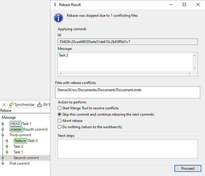
You decide to skip this commit and redo its changes manually after the rebase is completed.
You select Skip This Commit and Continue Rebasing the Next Commits, click Continue, and the rebase finishes successfully.
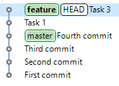
However, after attempting to reapply the changes from Task 2, you realize that this is extremely difficult. A better approach would have been to modify the original feature branch to avoid conflicts with master before rebasing.
To restore everything to its original state before the rebase, you need to undo the rebase process. But how can this be done if the changes have already been applied to the master branch, and the old commits from the feature branch seem to be gone?
In reality, as mentioned in section What Is Rebasing, the old commits of the feature branch are still in the object database, but they are no longer visible since they are not accessible from any branch. You can still access these commits and use them to undo the rebase.
To view the old commits of the feature branch, open the History panel and click ![]() (Show Menu), Show, and Additional References in the command bar. After this, the ORIG_HEAD reference will appear in the history, indicating the commit where HEAD was located before the rebase.
(Show Menu), Show, and Additional References in the command bar. After this, the ORIG_HEAD reference will appear in the history, indicating the commit where HEAD was located before the rebase.
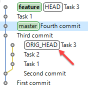
To undo the rebase, perform a hard reset to this commit by selecting Reset and Hard (HEAD, Index, and working tree) in the context menu. The feature branch checked out in the working tree will return to its state before the rebase.
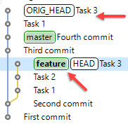
Although the Task 3 and Task 1 commits created during the rebase remain in the object database, they do not belong to the master branch. The pointer for this branch did not change during the rebase and still points to the Fourth Commit.
To ensure that the branch states have returned to their original state, disable the display of additional references in the History panel by selecting ![]() (Show Menu), Show, and Additional References.
(Show Menu), Show, and Additional References.
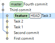
What Is Interactive Rebasing
Interactive rebasing allows you to quickly change the sequence of commits. For each commit, you can preselect one of the available actions and then apply them all at once.
-
Pick This action allows you to change the order of commits and move the selected commit forward or backward:
-
A new commit is created instead of this one.
-
New commits are created for all commits that follow this one.
-
New commits are also created for any commits affected by the change in order.
-
-
Skip This removes a commit:
-
The selected commit is excluded from history.
-
New commits are created for all commits that follow this one.
-
-
Edit This modifies a commit by adding changes to it:
-
A new commit is created instead of this one.
-
New commits are created for all commits that follow this one.
-
-
Squash This combines the changes and commit message of the selected commit into the previous commit:
-
A new commit is created instead of the previous one.
-
The selected commit is excluded from history.
-
New commits are created for all commits that follow this one.
-
-
Insert Without Message This adds only the changes from the selected commit into the previous commit, discarding the commit message:
-
A new commit is created instead of the previous one.
-
The selected commit is excluded from history.
-
New commits are created for all commits that follow this one.
-
-
Edit Message This changes the commit message:
-
A new commit is created instead of this one.
-
New commits are created for all commits that follow this one.
-
Warning: Interactive rebase rewrites commit history. Do not use interactive rebasing if you have already published your branch to a remote repository. Your colleagues may have already used the changes you published in their own development. Your interactive rebase will also force them to overwrite and modify their own changes. The only exceptions are branches intended exclusively for experiments or review purposes.
Perform an Interactive Rebase
To perform an interactive rebase, open the History panel.
-
Check out the branch you want to rebase.
-
Select the commit to which you want to rebase the checked-out branch, usually the parent commit.
-
Click Interactive Rebase in the context menu of this commit. To specify the operations to be applied to commits, 1C:EDT will open the Interactive Rebase panel.
-
Choose the desired actions for the commits.
-
Move commits up or down if needed.
-
Click Start to begin the interactive rebase.
Fastpath: If the result of the interactive rebase is unsatisfactory, you can revert to the original state just as you would with a standard rebase. See section How to Undo a Rebase for details.
Interactive Rebase Panel
The Interactive Rebase panel displays the rebase plan, including the sequence of commits and the actions to be run on each during the rebase.
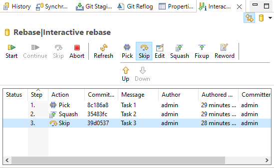
1C:EDT opens and populates this panel automatically when executing the interactive rebase command.
At the top of the panel, you will find rebase commands (Start, …, Abort), action selection commands (Pick, …, Edit Message), and commit movement commands (Move Up, Move Down).
Below these options, the table lists the commits that will be processed during the interactive rebase.
By default, 1C:EDT assigns the Pick action to all commits. Commits with this action can be moved up or down using the respective buttons in the command bar.
Your workflow in this panel may look like this:
- Move selected commits up or down.
- Assign the desired actions to the commits.
- Click Start to begin the interactive rebase.
- If interactive input is required during the process, it will pause until you take action. Click Continue to proceed with the rebase.
Command Bar
Rebase Commands
- Start to begin the interactive rebase.
- Continue to resume after completing necessary interactive actions.
- Skip to remove the current commit and continue rebasing.
- Abort to cancel the rebase and restore the original state.
Action Selection Commands
- Pick. This action allows you to change the order of commits and move the selected commit forward or backward:
- A new commit is created instead of this one.
- New commits are created for all commits that follow this one.
- New commits are also created for any commits affected by the change in order.
- Skip. This removes a commit:
- The selected commit is excluded from history.
- New commits are created for all commits that follow this one.
- Edit. This modifies a commit by adding changes to it:
- A new commit is created instead of this one.
- New commits are created for all commits that follow this one.
- Squash. This combines the changes and commit message of the selected commit into the previous commit:
- A new commit is created instead of the previous one.
- The selected commit is excluded from history.
- New commits are created for all commits that follow this one.
- Insert Without Message. This adds only the changes from the selected commit into the previous commit, discarding the commit message:
- A new commit is created instead of the previous one.
- The selected commit is excluded from history.
- New commits are created for all commits that follow this one.
- Edit Message. This changes the commit message:
- A new commit is created instead of this one.
- New commits are created for all commits that follow this one.
Commit Movement Commands
- Move Up to move the selected commit one row up.
- Move Down to move the selected commit one row down.
Context Menu
- Pick, Skip, Edit, Squash, Insert Without Message, and Edit Message perform the same actions as the corresponding command-bar buttons.
- Open Commit opens the commit in the commit viewer panel.
Synchronize
Branch Comparison (Synchronization)
Important: This command is not used when developing 1C:Enterprise applications. It compares two branches as a set of .xml files rather than as applications with their own structure of applied elements.
To compare 1C:Enterprise applications, use the command group Compare in the project context menu in the Navigator panel. In this case, the Compare and Merge Configurations Editor will open.
You can compare the working tree with a branch in several ways.
-
In the Navigator panel, click Version Control (Team) Advanced Features > Synchronize and select the desired branch.
-
In the Git Repositories panel, right-click a branch and select Synchronize with Working Tree.
1C:EDT will open the Synchronize perspective and the Synchronization panel.
Synchronization Panel
Important: The Synchronization panel is not used when developing 1C:Enterprise applications. This panel compares two branches as a set of .xml files rather than as applications with their own structure of applied elements.
To compare 1C:Enterprise applications, use the command group Compare in the project context menu in the Navigator panel. In this case, the Compare and Merge Configurations Editor will open.
The Synchronization panel allows you to check for differences between resources in the local directory and those in the local or remote branch.
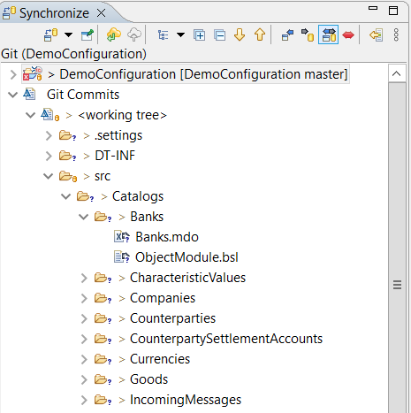
This panel is included in the standard perspectives of Synchronize and Git.
Opening the Synchronization Panel
In the main menu, click Window > Show View > Other... > Team Development > Synchronization.
Synchronize Perspective
Important: The Synchronize perspective is not used when developing 1C:Enterprise applications. This perspective compares two branches as a set of .xml files rather than as applications with their own structure of applied elements.
To compare 1C:Enterprise applications, use the command group Compare in the project context menu in the Navigator panel. In this case, the Compare and Merge Configurations Editor will open.
The Synchronize perspective allows synchronization of local storage resources with their counterparts in remote storage. It includes panels for synchronization, history tracking, and resource content comparison.
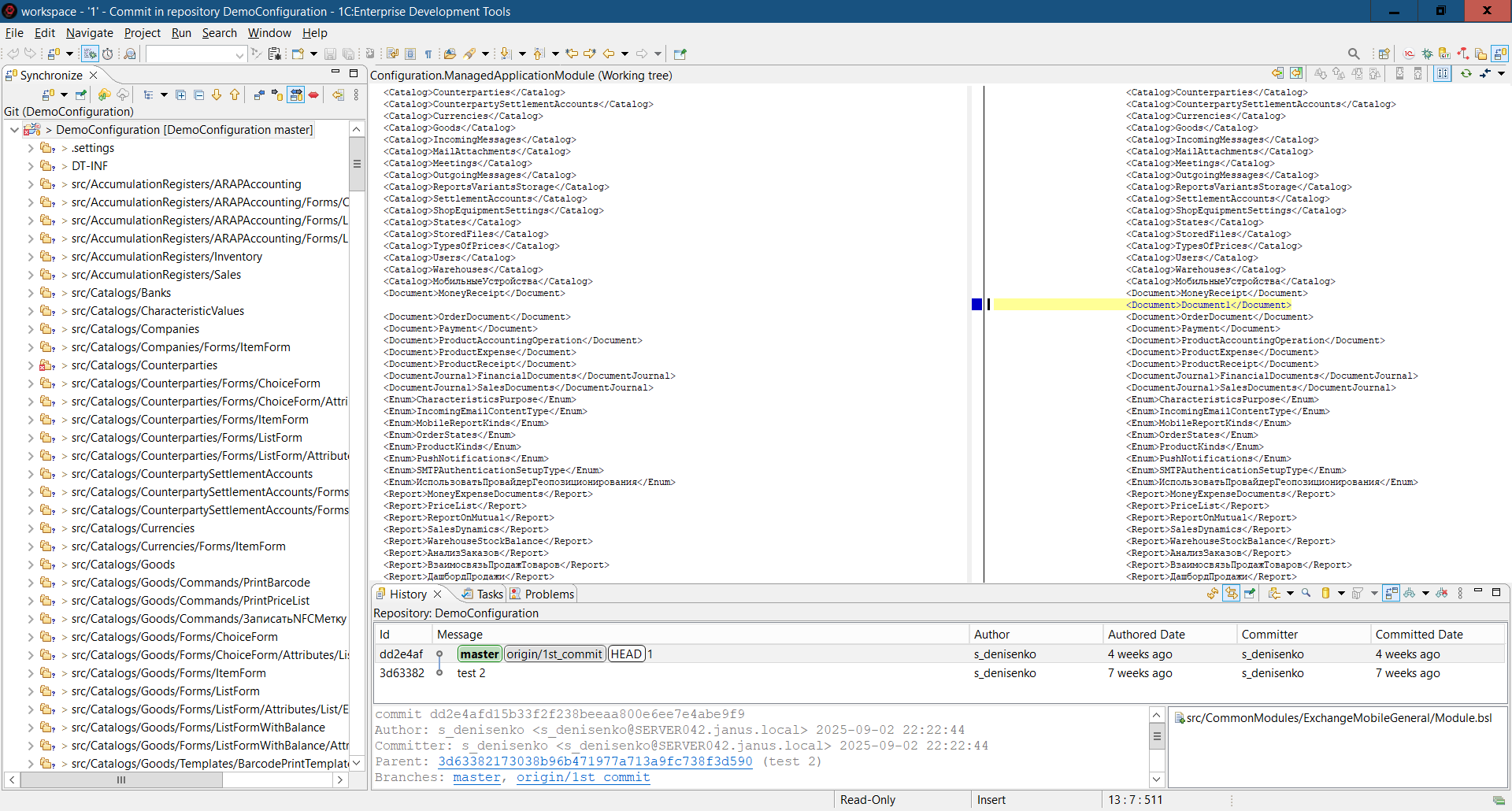
You can open this perspective in several ways.
-
In the Perspective Panel, click
(Open Perspective) Synchronize. -
In the main menu, click Window > Perspective > Open Perspective > Other... > Synchronize.
The standard set of the Synchronize perspective includes the following elements.
-
The Synchronization panel allows checking for differences between resources in the local directory and those in the local or remote branch.
-
The editor area, where the File Comparison Panel may open automatically to analyze differences between local and remote files.
-
Panels.
Tags
Tags allow you to mark specific points in the repository’s history as important.
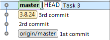
This functionality is typically used to label version releases.
Create Tag
There are several ways to create a tag.
-
In the History panel, right-click the required commit and select Create Tag... from the context menu.
-
In the Navigator panel, right-click the project and select Version Control (Team). Then go to Advanced > and choose Create Tag... from the context menu.
-
In the Development panel, click Version Control (Team) Advanced Options Create Tag... in the project's context menu.
-
In the Git Repositories panel, right-click a tag or the Tags group and select Create Tag... from the context menu.
Field Descriptions
-
Tag name is the name of the tag.
-
Tag message is the message attached to the tag. This message can later be viewed in the Properties panel. To do this, find the tag in the Git Repositories panel and click Show in. Then select Properties.
-
Existing tags is a field containing previously created tags. You can select a tag to modify its message or move it to a different commit.
-
If Force replace existing tag is selected, the tag message can be changed. When saved, the tag will be moved to the selected commit if it differs from the current one.
-
Additional Options: Choose commit that should be associated with this tag and select a commit from the list to link it to the new tag. If nothing is selected, the HEAD commit will be tagged.
-
Clear clears the tag name and message.
-
Create Tag and Start Push... creates the tag and opens the Tag Push Dialog to push tags to the remote repository.
-
Create Tag creates the tag.
Edit Tag
Editing a tag is most convenient in the History panel. However, it can also be done in any other panel where tag creation is available.
-
To change the message of an existing tag,
-
find the commit to which the tag is assigned.
-
Right-click it and select Create Tag... from the context menu.
-
In the Existing tags field, select tag A.
-
Check the Force replace existing tag box.
-
Modify the message in the Tag message field.
-
Click Create Tag.
-
-
If you want to assign tag A to a different commit,
-
find the new commit.
-
Right-click it and select Create Tag... from the context menu.
-
In the Existing tags field, select tag A.
-
Check the Force replace existing tag box.
-
Click Create Tag.
-
-
If you have already pushed the tag to the remote repository, it is better to create a new tag with a different name. Otherwise, anyone who has already used your tag will have to update it as well. If you are certain that no one else has used this tag in the remote repository, you can modify it.
-
Modify the tag using one of the methods described above, but do not complete the last step.
-
Finally, click Create Tag and Start Push... to push the changes to the remote repository.
-
In the second step of the wizard (Push Tags), check the box Force replace tags in remote repository and click Next.
-
Push Tags to Remote Repository
You can push a tag to the remote repository immediately when creating it. For this, use the command Create Tag and Start Push... in the dialog.
Additionally, tags that exist in the local repository can be pushed to the remote repository at any time. There are several ways to do this.
-
In the Navigator panel, right-click the project and select Version Control (Team) Remote Repository Push Tags... from the context menu.
-
In the Git Repositories panel, right-click:
-
Remote Repository Push Tags... in the repository context menu
or
-
Push Tags... or Push Tag... in the branch context menu.
-
-
In the Development panel, right-click the project and select Version Control (Team) Remote Repository Push Tags... from the context menu.
Field Descriptions
-
Remote is the remote repository where the tags will be pushed. You can select one from the available options.
-
Tags allows you to select the tags to be pushed.
-
Force replace tags in remote repository should be checked if the repository already contains these tags and they need to be overwritten with the new data.
-
Cancel push if result would be different than above because of changes on remote cancels the push if the result differs from the expected outcome due to remote repository changes.
-
Show dialog with result only when it is different from the confirmed result above displays the push result only if it differs from the expected outcome.
Find Tag
-
Open the History panel.
-
Click
(Show Find Toolbar) in the command bar to display the search field. -
Enter the tag name or a part of it.
-
The matching commit will be highlighted.
For more details on searching commits, read here.
Delete Tag
Important: Do not delete a tag if it has already been pushed to the remote repository. Doing so may disrupt version release tracking. Some Git servers even prevent tag deletion.
A tag can be deleted in several ways.
-
In the History panel, right-click the commit containing the tag to be deleted and select Delete Tag... from the context menu.
-
In the Git Repositories panel, right-click the tag and select Delete Tag... from the context menu.
Submodules
A submodule is a repository embedded within a parent repository. Standard development workflows in 1C:Enterprise do not typically use submodules.
However, 1C:EDT allows you to use submodules if necessary, as they are a standard Git feature. For learn more on submodules, read here.
Adding a Submodule by Cloning
To add a submodule, go to the Git Repositories panel and right-click the repository, then select Add Submodule... from the context menu.
- Submodule Path
- Submodule Path is the relative path to the submodule within the working tree of the parent repository.
- Git Repository
Select the repository that will be cloned and placed as a submodule.
In the URI field, specify the location of the remote repository. Example:
ssh://user@example.com:6888/dir/gitproject.git This is a remote server at example.com
http://example.com/dir/gitproject.git This is a remote server at example.com
file://\\example\gitproject This is a network computer named example
file://D:\dir\gitproject This is a local directory
After this, the remaining fields will be filled in automatically where possible.
Warning: When creating a local repository, set it up so that the repository directory and the 1C:EDT workspace are not nested within each other. To learn more, read here.
Field Descriptions
-
Location
-
URI This is the full URI of the remote repository or the file system path. To select a local directory, click Browse.... The repository directory is the one containing the .git folder.
-
Server This is the name of the remote server. If cloning from a local or network directory, this field will be empty.
-
Repository Path This is the path to the repository on the server or in the file system.
-
-
Connection
-
Protocol This is one of the supported protocols:
-
file This provides file access on a local computer or within a local network.
-
git This is the most efficient built-in Git protocol (default port 9418). This protocol does not support authentication and is usually used for anonymous read access to repositories.
-
ssh This is Git over the Secure Shell (SSH) protocol. It is typically used for authenticated write access to repositories. Note: If you are behind a firewall, you may need to configure proxy server settings: Window > Preferences... > General > Network Connections.
-
-
Port This is the server port.
-
-
Authentication
-
User This is the username for accessing the remote repository.
-
Password This is the password for accessing the remote repository.
-
Save in Secure Storage This saves authentication details in the Eclipse secure storage.
-
After clicking Finish, 1C:EDT will perform the following actions:
-
Clone the submodule
-
Add it to the index
-
Register it in the .gitmodules file
-
Register it in the .git/config file of the parent repository
Cloning a Repository with Submodules
When cloning a parent repository, you must also clone its submodules so that their files are available in the working tree of the parent repository.
To do this, on the third step of the Clone Wizard, check the box Clone Submodules.
Updating Submodules
There are two actions available: Update Submodule and Sync Submodule. Both are accessible in the Git Repositories panel under the Submodules node’s context menu or in the submodule’s own context menu.
Update Submodule fetches the commit specified in the parent repository's index for this submodule. If configured in the .git/config file of the parent repository, it will also perform a merge or rebase.
Sync Submodule updates the remote repository used by the submodule to the current value from the .gitmodules file located at the root of the parent repository’s working tree.
View Submodules
All submodules of a repository can be viewed in the Git Repositories panel under the Submodules node. They follow the same structure as standard repositories.
Development Panel
The Development panel displays the relationships between Git branches, created for the project, and infobases. This panel allows you to create and delete Git branches, modify their links to infobases, and perform other actions.

It opens automatically after creating a new branch.
Opening the Development Panel
Click Window > Show View > Other… > 1C:Enterprise > Development in the main menu.
Structure of Information in the Panel
At the top level of the hierarchy are projects  within your workspace. If you have only one project, this hierarchy level is omitted.
The second level contains task groups  . A task represents a single technical project or a bug fix. For example, all technical projects are grouped under feature, while all bug fixes are under bugfix.
The third level consists of tasks  . Since there is only one main development branch, master, the management of this branch does not belong to any task group and is displayed at the second hierarchy level alongside task groups.
At the fourth level are Git branches  and the infobases
  associated with them. If no infobase is linked to a Git branch, that branch and its respective task are not displayed in the panel.
Legend
-
is a project. Depending on the type of project, other notations may also be used.
-
is a task group.
-
is a task.
-
is a Git branch.
-
is an infobase. Depending on the type of infobase, other notations may also be used.
Mouse Actions
-
A single click on an infobase opens its properties in the Properties panel.
-
A double click on a project, task group, or task expands or collapses the selected group.
Command Bar
-
(Collapse All) Collapses all hierarchy levels in the panel down to the first level.
-
(Refresh) Updates the information in the panel.
-
(Create New Branch...) creates a new branch using 1C:EDT (links it to a new or existing infobase).
-
 (Configure Branch...) modifies the existing Git branch links to an infobase.
Project Context Menu
-
Restore from Local History... Restores deleted configuration objects from local history.
-
Version Control (Team) submenu contains the following commands.
-
Commit... opens the Git Staging panel for committing project changes to the local repository.
-
Stashes submenu contains the following commands.
-
Push to origin sends changes to the remote repository named "origin".
-
Fetch from Upstream retrieves changes from the upstream repository, from the remote branch associated with the local branch.
-
Push Branch 'branch-name'... sends the selected branch to the remote repository. You can choose a repository or create a new one, select the branch to push, and configure push and fetch settings for the remote repository.
-
Pull fetches changes from the upstream repository and merges them into the current branch.
-
Pull... fetches changes from the selected remote repository and merges them into the current branch.
-
Create New Branch... creates a new branch using 1C:EDT (links it to a new or existing infobase).
-
Switch To switches the project to a different branch. The submenu provides options to choose from local branches in the current repository. It also includes options to create a new branch or select from other repository elements such as tags and remote tracking branches.
-
Delete Branch... deletes a Git branch and, optionally, its linked infobase. The current branch, to which the project is switched, cannot be deleted.
-
Remote Repository submenu contains the following commands.
-
Push... sends changes to the selected remote repository.
-
Push Tags... sends the selected tags to the remote repository.
-
Fetch From... retrieves changes from the selected repository that are missing in the local object infobase.
-
Configure Push to Upstream... allows configuring push settings to the upstream repository.
-
Configure Fetch from Upstream... allows configuring fetch settings from the upstream repository.
-
-
Switch To switches the project to a different branch. The submenu provides options to choose from local branches in the current repository. It also includes options to create a new branch or select from other repository elements such as tags and remote tracking branches.
-
Advanced Options submenu contains additional commands.
-
Rename Branch... renames the branch.
-
Delete Branch... deletes the branch using standard Git tools.
-
Synchronize Not used in 1C:Enterprise application development. Synchronizes the working tree with the selected branch of the chosen repository. This is done using the Synchronize perspective. The submenu contains additional commands besides local repository branches.
- Custom... opens a dialog for selecting a repository.
-
Create Tag... creates a tag.
-
Clean... removes files and folders from the working tree that are not under version control.
-
Assume Unchanged marks a file as Assume Unchanged.
-
No Assume Unchanged removes the Assume Unchanged mark from the file.
-
Remove from Version Control removes the object from Git version control but leaves it in the working tree.
-
Synchronize Workspace synchronizes the working tree with the remote repository. This is done using the Synchronize perspective.
-
Merge Tool resolves merge conflicts using the standard merge tool.
-
Reset... reverts the changes made in the working tree.
-
Create Patch... creates a patch.
-
Apply Patch applies a patch.
-
Ignore adds the file to .gitignore so that Git ignores it (learn more).
-
Show in Git Repositories Panel opens the project in the Git Repositories panel.
-
Disconnect disconnects all Git Team providers from this project. The Git repository continues to exist, but 1C:EDT no longer interacts with it.
-
-
Merge... merges the selected branch into the current branch.
-
Rebase... moves the changes from the current branch to the selected branch.
-
Add to Index adds the selected files from the Unstaged Changes section to the index.
-
Show History opens the History panel and displays resources from the current repository.
-
-
Compare submenu contains the following commands:
-
Compare with Each Other Not used in 1C:Enterprise application development. Compares projects with each other.
-
HEAD Revision Not used in 1C:Enterprise application development. Compares this resource in the working tree with the last commit.
-
Index Not used in 1C:Enterprise application development. compares this resource in the working tree and in the index.
-
Previous Revision Not used in 1C:Enterprise application development. Compares this resource with the previous commit.
-
Branch, Tag, or Reference... Not used in 1C:Enterprise application development. Compares the working tree with the selected branch, tag, or reference.
-
Commit... Not used in 1C:Enterprise application development. Compares the working tree with the selected commit.
-
-
Replace With submenu contains the following commands.
-
HEAD Revision replaces the working tree with the last commit.
-
Index replaces the working tree with the index.
-
Previous Revision replaces the working tree with the previous revision.
-
Branch, Tag, or Reference... replaces the working tree with the selected branch, tag, or reference.
-
Commit... replaces the working tree with the selected commit.
-
-
Refresh Updates the information in the panel.
Task Context Menu
-
Create New Branch... creates a new branch using 1C:EDT (links it to a new or existing infobase).
-
Configure Branch... modifies the existing Git branch links to an infobase.
-
Delete Branch... deletes a Git branch and, optionally, its linked infobase. The current branch, to which the project is switched, cannot be deleted.
-
Refresh Updates the information in the panel.
Branch Context Menu
-
Check Out switches the project to this branch.
-
Push to origin sends changes to the remote repository named "origin".
-
Delete Branch... deletes a Git branch and, optionally, its linked infobase. The current branch, to which the project is switched, cannot be deleted.
-
Merge... merges the selected branch into the current branch.
-
Reset... reverts the changes made in the working tree.
-
Refresh Updates the information in the panel.
Infobase Context Menu
-
Run Designer Launches the 1C:Enterprise platform and opens the infobase in Designer mode (about selecting the platform version).
-
Update Configuration... Exports the configuration from the project to the infobase (about selecting the platform version) and then updates the database configuration.
-
Import Configuration... Exports the configuration from the project to the infobase (about selecting the platform version) and then updates the database configuration.
-
Import Extensions... Imports extensions from the infobase into new extension projects.
-
Save Configuration to File... Saves the configuration or extension contained in the infobase to a .cf file.
-
Dump Infobase... Exports the infobase to a .dt file.
-
Load Infobase... Loads an infobase from a .dt file.
-
Publish Infobase... Publishes the infobase on the web server.
-
Publish Mobile Application... Publishes the mobile application on the web server.
-
Refresh Updates the information in the panel.
Chapter 12. Automating Testing with Deployment of Changes to Working Infobases
Advancements in information technology continuously reshape software development and implementation requirements. In a fast-changing business landscape and an increasingly dynamic market, it is crucial to adopt efficient methods and tools that accelerate and automate development, testing, and software deployment.
This is why the DevOps methodology has been gaining widespread adoption year after year. DevOps is a software development strategy that fosters close collaboration between development and operations teams.
Its main goal is to merge development, testing, and software deployment into a seamless, continuous process.
Batch Installation of 1C:EDT and the 1C:Language Tool Plugin
When organizing CI/CD pipelines, batch installation of the development environment and, possibly, certain plugins is required.
Below are examples of Docker image configuration files in the Linux operating system for 1C:EDT and the 1C:Language Tool plugin.
Installing 1C:EDT
Note: The variable JAVA_DEB_URL must be predefined.
# Install OpenJDK+JFX
    mkdir -p /tmp/java; \
    curl -f -o /tmp/java/jdk.deb "$JAVA_DEB_URL"; \
    apt install --no-install-recommends -y /tmp/java/jdk.deb; \
    rm -rf /tmp/java; \
    ls /usr/lib/jvm; \
    ls $JAVA_HOME; \
    echo "ru_RU.UTF-8 UTF-8" >> /etc/locale.gen \
      && locale-gen ru_RU.UTF-8 \
      && update-locale; \
# Install 1C:EDT
    mkdir -p /tmp/edt; \
    curl -f -o /tmp/edt/1cedt.tar.gz "$EDT_URL"; \
    tar -xvf "/tmp/edt/1cedt.tar.gz" -C "/tmp/edt"; \
    rm -f "/tmp/edt/1cedt.tar.gz"; \
    chmod +x /tmp/edt/1ce-installer-cli \
&& /tmp/edt/1ce-installer-cli install --ignore-hardware-checks --ignore-signature-warnings; \
    rm -rf /tmp/edt; \
    ls /opt/1C/1CE/components; \
    dbus-uuidgen > /var/lib/dbus/machine-id; \
    mem_limit=$( sed -n 's/^-Xmx//p' "$EDT_HOME/1cedt.ini" ); \
    echo Changing default memory limit from ${mem_limit} to ${EDT_MEMORY_LIMIT}; \
    sed -i "s/^\(-Xmx\).*$/\1$EDT_MEMORY_LIMIT/" "$EDT_HOME/1cedt.ini"; \
    cat "$EDT_HOME/1cedt.ini"; \
    cat "$EDT_HOME/configuration/config.ini"; \
    chmod +x /usr/bin/ring; \
    ls $EDT_HOME; \
    chmod +x /usr/bin/1cedtcli; \
Installing 1C:Language Tool
Note: The variable LANGTOOL_DISTR_SERVER must be predefined.
# Install 1C:Language Tool
    $EDT_HOME/1cedt
        -clean
        -purgeHistory
        -application org.eclipse.equinox.p2.director
        -noSplash
        -repository  "${LANGTOOL_DISTR_SERVER}/repo.zip!"
        -installIUs com.e1c.langtool.v8.dt.feature.feature.group,
                    com.e1c.langtool.microsoft.feature.feature.group,
                    com.e1c.langtool.yandex.feature.feature.group,
                    com.e1c.langtool.google.feature.feature.group; \
Chapter 13. Command Line Interface
To start 1C:EDT from the command line, you can use the extensible interface 1C:EDT CLI. This interface has been available since version 2023.1.0. This interface offers extensive functionality and supports variables, data types, pipelines (pipes), service commands, and procedural commands. and allows custom commands to be added.
Starting from version 2024.1, the old command line interface ring CLI is no longer supported. We are keeping its description in the documentation for now, as it may be useful when transitioning automated builds to the 1C:EDT CLI interface.
1C:EDT Command Line Interface (1C:EDT CLI)
Warning: The 1C:EDT CLI command line interface should not be used with workspaces created in versions of 1C:EDT earlier than 2023.1.0.
Troubleshooting: To use 1C:EDT CLI, administrator rights are required.
Application for Running 1C:EDT CLI
-
Windows: 1cedtcli.exe
-
Linux, macOS: 1cedtcli
The application is located in the 1C:EDT executable directory.
Troubleshooting: The first launch of 1C:EDT CLI may take about 25 seconds.
Three Execution Modes
-
Interactive Mode After starting 1cedtcli, the prompt 1C:EDT> appears, waiting for interactive command input.
-
Execute a Single Command Runs a single command specified at startup 1cedtcli.
-
Execute a Sequence of Commands from a File Runs a sequence of commands from a specified file at startup 1cedtcli.
Options
Command line options can be specified in any order, except:
-
-command This option must be the last one because everything following it is interpreted as a command.
-
-vmargs This option must be placed before -command (or be the last option if -command is not used) because all arguments between it and -command are treated as JVM arguments.
Available Options
-
-data Specifies the location of the 1C:EDT workspace.
Example: The following command launches 1C:EDT CLI in interactive mode:
1cedtcli -data D:\projects\MyProject -
-timeout Sets the maximum execution time in seconds for a command or sequence of commands. If execution does not finish within the specified time, it is terminated, and a thread dump is recorded to help diagnose the cause of the issue. If not explicitly set, the default timeout is 60 minutes.
Example: This command launches a command sequence from the file script.txt with a 90-minute timeout:
1cedtcli -data D:\projects\MyProject -timeout 5400 -file D:\projects\script.txt -
-vmargs Specifies one or more JVM arguments (e.g., -Xmx, -D, etc.).
Example: To increase the heap size to 8 GB during project import:
1cedtcli -data D:\projects\MyProject -vmargs -Xmx8g -command import --configuration-files D:\XML-1 --project D:\project-1 -
-ini-file Specifies the path to the 1C:EDT configuration file from which settings will be loaded for launching 1C:EDT CLI. If not specified, the default configuration file 1cedt.ini is used from the 1C:EDT executable directory.
-
-v Enables verbose output.
-
-V Displays the application version 1cedtcli.
Example:
>1cedtcli -V 1.30.0-SNAPSHOT Build: 2 Revision: bab3b67830e78ed251940c29e2687edf613457d7 -
-h Displays help information.
-
-nl Specifies the language for 1C:EDT CLI messages. If not set, 1C:EDT CLI uses the system language.
For example, the following command displays help in English:
1cedtcli -h -nl en_US -
One of the following options:
-
-command Specifies the command to execute along with its arguments. Example: Optimizing project storage format (clean-up-source):
1cedtcli -data D:\projects\MyProject -command clean-up-source --project-name Demo_EDT -
-file Specifies the path to a file containing the commands to be executed. Example:
1cedtcli -data D:\projects\MyProject -file D:\projects\script.txtAfter the filename, you can specify one or more arguments that will be passed to the executable file. These arguments will be available in the script as variables $1, $2, etc.
The total number of arguments is stored in the $argc variable.
The variable $0 contains the path to the executable file.
-
Interactive Mode
To launch 1C:EDT CLI in interactive mode, after 1cedtcli, specify the option -data, which indicates the location of the workspace. Example:
1cedtcli -data D:\projects\MyProject This will open a command-line interpreter displaying the prompt: 1C:EDT> After that, you can enter 1C:EDT CLI commands.
Executing a Single Command
To execute a single command, after 1cedtcli specify:
-
The -data option to set the workspace location.
-
The -command option followed by the command and its arguments.
Example:
1cedtcli -data D:\projects\MyProject -command clean-up-source --project-name Demo_EDTExecuting a Sequence of Commands
To execute a sequence of commands, after 1cedtcli specify:
-
The -data option to set the workspace location.
-
The -file option with the path to the file containing the commands.
Example:
1cedtcli -data D:\projects\MyProject -file D:\projects\script.txtCommands
build
This command cleans and rebuilds all or selected projects. It is equivalent to the interactive command Project > Clean.... Optional argument:
--yes. If this argument is set to true or left unspecified, 1C:EDT rebuilds all projects in the workspace.
Example:
build --yesIf this argument is set to false or omitted, confirmation will be required before rebuilding all projects:
1C:EDT> build
Please confirm the build for the following projects:
 pr24
 pr24.WeightOfGoods
 pr24.Headers
Proceed with the build? (y/n. default=n)
If project names are listed after this argument, only the specified projects will be rebuilt:
build --yes [pr24 pr24.Headers]clean-up-source
Optimizes the project storage format. Has one of the following required arguments:
--projectSpecifies the path to the 1C:EDT project directory whose storage format should be optimized. If this project is not imported into the workspace specified in the-dataparameter, it will be imported before optimizing its storage format.--project-nameSpecifies the name of the 1C:EDT project whose storage format should be optimized.
Example:
clean-up-source --project-name Demo_EDTdelete
Deletes all or selected projects. Optional argument:
--yesIf set to true or left unspecified, 1C:EDT deletes all projects in the workspace.
Example:
delete --yesIf set to false or omitted, confirmation will be required before deleting all projects:
1C:EDT> delete
Please confirm deletion of the following projects:
 pr24
 pr24.WeightOfGoods
 pr24.Headers
Confirm deletion? (y/n. default=n)
If project names are listed after this argument, only the specified projects will be deleted:
delete --yes [pr24 pr24.Headers]exit
Exits interactive command-line mode. Optional arguments:
--yesIf set to true or left unspecified, the exit will proceed without confirmation.--statusReturn code.
Example:
exit --yesIf set to false or omitted, confirmation will be required before exiting:
1C:EDT> exit
Are you sure you want to exit? (y/n. default=y)
export
Exports a 1C:EDT project to .xml configuration files. Accepts the following arguments:
- One of the following required arguments:
--projectPath to the 1C:EDT project directory to be exported. If the project is not imported into the workspace specified in the-dataparameter, it will be imported before exporting it to .xml configuration files.--project-nameName of the 1C:EDT project to be exported.
--configuration-filesRequired argument. Target directory for the .xml configuration files.
Example:
export --project D:\Demo_EDT --configuration-files D:\xml-fileshelp
Displays a list of available commands.
Example:
helpTo get help for a specific command, enter its name after help.
Example:
help install-platform-supportimport
Imports can be used in two ways.
1. Imports a 1C:EDT project into the workspace. Required argument:
--projectPath to the 1C:EDT project directory to be imported.
Example:
import --project D:\Demo_EDT2. Imports .xml configuration files into a 1C:EDT project. Accepts the following arguments:
--versionOptional. Specifies the "1C:Enterprise" platform version to be assigned to the new project, for example, 8.3.22. If not specified, the version will be determined based on the .xml configuration files.--base-project-nameName of the base project. Allowed only for extension projects or for external report and data processor projects.--configuration-filesRequired argument. Directory containing the .xml configuration files.--buildIf this argument is set to true, the command will wait for the project to finish building, allowing the subsequent import command in step 1 to import the project into the workspace.- One of the following required arguments:
--projectPath to the 1C:EDT project directory where the .xml files should be imported. If the directory already contains files, the new files will be added to the existing ones. If the project is not imported into the workspace specified in the-dataparameter, it will be imported before the .xml files are added.--project-nameName of the 1C:EDT project where the .xml files should be imported. If the project already exists in the workspace specified in the-dataparameter, an error will occur.
Example:
import --configuration-files D:\xml-files --project D:\Demo_EDT
import --base-project-name Demo_EDT --configuration-files D:\xml-files --project D:\Demo_EDT.WeightOfGoods
import --version 8.3.24 --base-project-name Demo_EDT --configuration-files D:\xml-files --project D:\Demo_EDT.WeightOfGoods
install-platform-support
Installs support for the specified version of the "1C:Enterprise" platform. Required argument:
--versionSpecifies the platform version to install support for.
Example:
install-platform-support --version 8.3.10platform-versions
Displays the list of platform versions supported by the development environment.
Example:
1C:EDT> platform-versions
8.3.21
8.3.22
8.3.23
8.3.24
project
Displays information about all or selected projects. Optional argument:
--detailsIf set to true or left unspecified, 1C:EDT displays information for all projects in the workspace.
1C:EDT> project --details
Name: pr24
Content: C:\Users\Test\AppData\Local\1C\1cedtstart\projects\pr24\pr24
Name: pr24.WeightOfGoods
Content: C:\Users\Test\AppData\Local\1C\1cedtstart\projects\pr24\pr24.WeightOfGoods
Name: pr24.Headers
Content: C:\Users\Test\AppData\Local\1C\1cedtstart\projects\pr24\pr24.Headers
If set to false or omitted, only a simple list of project names is displayed:
1C:EDT> project
pr24
pr24.WeightOfGoods
pr24.Headers
If specific project names are listed after this argument, only those projects will be displayed:
project --details [pr24 pr24.Headers]sort-project
Sorts configuration objects according to automatic sorting settings. If automatic sorting was not enabled for a project, default automatic sorting settings will be applied. Has one of the following required arguments:
--project-listList of paths to 1C:EDT project directories where sorting will be run. All nested projects will also be processed. If any of these projects have not been imported into the workspace specified in the-dataparameter, the project will be imported into the workspace before sorting.--project-name-listA list of project names previously imported into the workspace that will be sorted.
Paths or names should be separated by spaces inside square brackets. If only one path or name is specified, square brackets are not required.
Example:
sort-project --project-list [D:\Demo_EDT D:\Demo_EDT.WeightOfGoods]
sort-project --project-list D:\Demo_EDT
uninstall-platform-support
Removes support for the specified version of the "1C:Enterprise" platform. Required argument:
--versionSpecifies the platform version to remove support for.
Example:
uninstall-platform-support --version 8.3.10validate
Validates a project and outputs the result to a .tsv file. Accepts the following arguments:
--fileSpecifies the path to the .tsv file where validation results will be saved. If the file already exists, an error will be returned.- One of the following required arguments:
--project-listList of paths to 1C:EDT project directories where validation will be run. If a project is not imported into the workspace specified in the-dataparameter, it will be imported before validation.--project-name-listList of project names previously imported into the workspace to be validated.
Paths or names should be separated by spaces inside square brackets. If only one path or name is specified, square brackets are not required.
Example:
validate --file D:\validation-result.tsv --project-list [D:\Demo_EDT D:\Demo_EDT.WeightOfGoods]
validate --file D:\validation-result.tsv --project-list D:\Demo_EDT
Return Code
If 1C:EDT CLI needs to return exit code 23 or 24 (for example, because it was returned by a command executed in -command mode or by the last command in a sequence executed in -file mode), the return code will be increased by 100, meaning it will return 123 or 124 instead. This is necessary because 23 and 24 are special Eclipse return codes with their own semantics.
Command Language
1C:EDT CLI supports many shell scripting features, some of which are extended. Key Features of the Command Language:
-
Variables:
-
Define a variable:
var = abcd -
Use a variable:
$var -
Standard Variables:
-
$1,$2, etc. are arguments passed to the executable file -
$argcis the number of arguments passed -
$0is the path to the executable file
-
-
-
Data Types:
-
Basic types: string, integer, floating point
-
List:
list = [1 2 a b] -
Map:
map = [Jan=1 Feb=2 Mar=3]
-
-
Pipelines (pipes):
command1 | command2 -
Utility Commands: echo, grep, cat
-
Procedural Commands (conditional statements, loops, etc.): if, not, each, while, until
More details about the command language and its capabilities can be found here (in English).
Example 1
The example prints a message indicating whether version 8.3.22 of "1C:Enterprise" is supported by this development environment.
is22 = ( platform-versions | grep -q 8.3.22 )
if { $is22 } { echo 8.3.22 is supported } { echo 8.3.22 is not supported }
8.3.22 is supported
In the first line, a variable is22 is created to store the result of executing the command inside the parentheses. Inside the parentheses, the command platform-versions outputs all supported platform versions, and its output is redirected to the grep command, which searches for the string "8.3.22" within it. The option -q ensures that the grep command does not output anything but simply returns true or false.
In the second line, the if command checks whether the variable is22 is true, and the echo commands print the respective message.
Example 2
The example prints a message indicating whether each of the specified "1C:Enterprise" versions is supported by this development environment.
isList = [8.3.21 8.3.22 8.3.23]
each $isList { if { not { platform-versions | grep -q $it } } { "$it is not supported" } { "$it is supported" } }
8.3.21 is supported
8.3.22 is supported
8.3.23 is not supported
In the first line, a list variable containing the versions of interest is created.
In the second line, the if command checks each version to determine whether it is supported, and prints the respective message.
Example 3
The example reads the contents of a file.
hellotxt = ( cat /home/dmitry/hello.txt )
This is the content of the file hello.txt.
In the first line, the cat command reads the contents of the file /home/test/hello.txt into the variable hellotxt.
Custom Commands
You can add custom commands to the 1C:EDT CLI command-line interface. To do this, you need to write a plugin for 1C:EDT that connects to the extension point com.e1c.g5.v8.dt.cli.api.cliCommand and implements the interface com.e1c.g5.v8.dt.cli.api.ICliCommand.
You can read more about developing custom command-line commands here.
For testing custom 1C:EDT CLI commands, you can use the tool described here.
A demonstration example of a plugin can be found here.
Scripts
A 1C:EDT CLI script is a text file containing 1C:EDT CLI commands and shell instructions, which can be run using the -file option and can accept arguments accessible in the script as variables $1, $2, and so on. In a simple case, the script contains one or more 1C:EDT CLI commands executed sequentially. Script files usually have the .1cedtcli extension.
Loading Scripts
Scripts supplied with 1C:EDT are loaded automatically. You can get their list using the script command.
You can load external scripts that are not part of the 1C:EDT installation package in several ways:
-
List paths to script directories in the EDTCLI_SCRIPT_PATH environment variable. The format is similar to the PATH variable;
-
Use the script --load command.
In both cases, all files with the .1cedtcli extension from the specified directories will be loaded. The script name will be the file name without the extension. The file name must not contain special characters.
Fastpath: You can disable automatic loading of specific scripts. To do this, write a plugin for 1C:EDT that connects to the com.e1c.g5.v8.dt.cli.api.cliVerifier extension point and implements the com.e1c.g5.v8.dt.cli.api.ICliVerifier interface. Read more here.
Running Scripts
Scripts can be run like regular commands:
<script name> <argument1> <argument2> ...They also work with the help command.
For example, create a file hello.1cedtcli with the following content:
# The script greets the user.
#
# Usage:
#    hello "name"
# Arguments:
#    name - the user's name. If not specified, greets the world.
#
# Additionally, the script prints its location.

name = world
if { $1 } {
   name = $1
}

echo Hello, $name!
echo Script location: $0
Launch 1C:EDT CLI in interactive mode and load this script:
1C:EDT> script --load "C:\Users\test\cli-scripts\hello.1cedtcli"
hello
The hello output above means that the script was loaded successfully. Now you can get help on it:
1C:EDT> help hello
The script greets the user.

Usage:
   hello "name"
Arguments:
   name - the user's name. If not specified, greets the world.

Additionally, the script prints its location.
You can also run it like a regular command in interactive mode.
1C:EDT> hello
Hello, world!
Script location: C:\Users\test\cli-scripts\hello.1cedtcli
1C:EDT> hello John
Hello, John!
Script location: C:\Users\test\cli-scripts\hello.1cedtcli
If you want to use this script in single-command execution mode, you need to set the environment variable:
EDTCLI_SCRIPT_PATH=C:\Users\test\cli-scriptsIf a directory is specified, all scripts from it will be loaded. You can also:
-
Specify a path to a file, in which case only that script will be loaded..
-
Specify multiple paths using the standard separator In Windows, the separator is a semicolon (
;); in Linux and macOS, it is a colon (:).
Now you can run the script in single-command execution mode:
1cedtcli -data C:\Users\test\workspace -command hello JohnYou can also view the script content (its code) using the script -c/--content command.
Any external script not part of the installation package can also be run using the -file option. This does not require registering it in the EDTCLI_SCRIPT_PATH variable.
1cedtcli -data C:\Users\test\workspace -file C:\Users\test\cli-scripts\hello.1cedtcli JohnDelivery and Testing of Scripts
You can include your script in the 1C:EDT distribution. To do this, write a plugin for 1C:EDT, add the script file to it, and connect to the com.e1c.g5.v8.dt.cli.api.cliScript extension point.
You can also implement automatic testing of the delivered scripts similar to how integration tests are done for commands.
Read more about this here.
Scripting Language
Comments
The hash symbol (#) and the rest of the line after it are considered a comment.
If the script begins with a comment, that comment is treated as the script's help text and will be displayed by the help command.
Literals and Variables
The following types of literals are supported:
-
String:
"abcd", quotes are optional; -
List:
[1 2 a b]; -
Map:
[Jan=1 Feb=2 Mar=3]; -
Closure:
{ echo hi $args }(details).
You can define a variable like this: a = test. Access a variable's value: $a.
Important: Commands can return any Java object as a result, so a variable can hold an object of any Java class.
Predefined Variables
The following variables are defined automatically when the script is executed:
-
$0is the path to the executing script file. For an installation package script, this is the resource path (see Script Delivery); -
$argcis the number of passed arguments; -
$1, $2, ...are arguments passed to the script.
Sequential Command Execution and Output Redirection
To execute multiple commands in one line, use the semicolon (;):
echo a; echo bYou can redirect the output of one command into the input of another (pipes):
1C:EDT> platform-versions | grep 8.3.22
8.3.22
true
You can redirect command output to a variable using parentheses:
1C:EDT> q = (echo abcd)
abcd
1C:EDT> $q
abcd
You can redirect command output to a file using the greater-than symbol >:
1C:EDT> platform-versions > /home/test/platform-versions.txt
1C:EDT>
Closures
A closure is a block of code that can be stored in a variable or passed as an argument to a command for later execution. Defined using curly braces:
1C:EDT> hi-func = { echo Hello, $args! }
echo Hello, $args!
1C:EDT> hi-func Someone
Hello, Someone!
In interactive mode, closures must be one line. Multiline closures are allowed in scripts. In this case, the opening brace must be on the same line.
Correct:
hi-func = {
    echo Hello, $args!
    echo How are you?
}
Incorrect:
hi-func =
{
    echo Hello, $args!
    echo How are you?
}
Execution Control
Execution control commands take closures as arguments and follow closure formatting rules.
Correct:
if { condition } {
    action
}
Incorrect:
if { condition }
{
    action
}
Conditionals
if { condition } { action if true } { action if false }The final block, else, is optional.
The condition can be the result of a command, script, or variable value. The following values are considered false:
nullfalse\(boolean\)0\(number\)0\(string\)- an empty string
- a string of only whitespace
- any empty collection
All other values are considered true.
You can invert a condition using the not { condition } command.
Loops
while { condition } { action while true }
until { condition } { action while false }
Truth conditions are the same as for conditionals.
each $collection { action }Executes the action for each item in the collection. The current item is accessible via it, see example 2.
Exception Handling
try { main } { on error } { finally }
same as above but more readable:
try { main } catch { on error } finally { finally }
Equivalent to try / catch / finally in Java. Executes the main block. If an exception occurs, the error block is executed. The finally block is always executed.
The third block, finally, is optional.
For try / finally without catch, use:
try { main } finally { finally }To throw an exception:
throw string/number/any objectThrown exceptions are available in the exception variable. The variable contains the exception object; you can call its methods, such as message or printStackTrace:
1C:EDT> throw "An error occurred"
edtsh: An error occurred
Enter '$exception printStackTrace' for details.
1C:EDT> $exception message
An error occurred
Successful commands reset the exception variable. To keep the exception info for later use, save it to another variable: handle_later = $exception.
Service Commands
echo: output
1C:EDT> echo Hello, world!
Hello, world!
grep: search
1C:EDT> platform-versions | grep -q 8.3.24
true
Optional arguments:
-i,--ignore-case: ignore case-n,--line-number: add line numbers-q,--quiet,--silent: suppress all normal output-v,--invert-match: select non-matching lines
cat: read files
cat /home/test/hello.txtDisplays the file content to the console.
cd: current working tree
cd
cd /path/to/new/working/directory
The first form shows the current working tree, which affects all relative paths. The second form changes the working tree.
env: environment variables
env
env PATH
The first form shows all environment variables. The second form shows the value of the specified variable.
Java Interaction
All variables are Java objects of defined types, and you can call methods or access properties. The syntax is:
$<variable> <method or property> [args]Example:
1C:EDT> a = [1 2 abcd]
1
2
abcd

1C:EDT> $a size
3
1C:EDT> $a get 2
abcd
1C:EDT>
Here, you create a list with 3 elements. The variable a is then of type java.util.List<Object>. You call the size() method to get the size of the list. Then you call the get(2) method to get the last item.
If the type has a getter method like getSomething(), you can call it as $a something (without get). See the last exception handling example:
$exception messageThis calls the getMessage() method on the exception object.
Script Examples
Example 1
This example displays whether version 8.3.22 of 1C:Enterprise is supported by the development environment.
is22 = ( platform-versions | grep -q 8.3.22 )
if { \$is22 } { echo 8.3.22 is supported } { echo 8.3.22 is not supported }
Output:
8.3.22 is supportedIn the first line, you create a variable is22 and assign it the result of the command in parentheses. The command platform-versions lists all supported platform versions, and its output is piped to grep, which searches for the string 8.3.22. The -q argument tells grep to suppress output and return either true or false.
The if command checks the truth of is22, and the echo commands print the corresponding message.
Example 2
This example shows whether each specified version of 1C:Enterprise is supported by the development environment.
isList = [8.3.21 8.3.22 9.3.23]
each \$isList {
    if { not { platform-versions | grep -q \$it } } {
        "\$it is not supported"
    } {
        "\$it is supported"
    }
}
Output:
8.3.21 is supported
8.3.22 is supported
9.3.23 is not supported
In the first line, you create a list variable of the desired versions. In the second line, the if command checks support for each version and prints the appropriate message.
Example 3
This example reads the contents of a file.
hellotxt = ( cat /home/test/hello.txt )In the first line, the cat command reads the contents of the file /home/test/hello.txt into the hellotxt variable.
Java Virtual Machine Arguments
JVM (Java Virtual Machine) arguments can be used to configure several important 1C:EDT features such as the amount of memory available to the JVM, the location of the temporary directory, and others.
JVM arguments can be specified in three places:
-
In the 1C:EDT CLI command line using the -vmargs option;
-
In the 1cedt.ini file (JVM arguments are listed after the
-vmargsline); -
In the 1C:EDT Start launcher and updater:
You might need the following arguments:
-Xmx
Amount of memory available to the JVM. Default is 4 GB:
-Xmx4096mYou can set 8 GB:
-Xmx8g-Djava.io.tmpdir
Path to the temporary directory, for example:
-Djava.io.tmpdir=C:tmp-DcoreLimit
Number of CPU threads 1C:EDT uses for the following resource-intensive operations:
- Importing data into 1C:EDT;
- Comparing and merging configurations;
- Building language data;
- Configuration checks.
By default, the number of threads is not limited. You can limit it to four:
-DcoreLimit=4-DdisableProjectChecks
Disable full checks, for example:
-DdisableProjectChecks=trueWarning: Note that when full checks are disabled, strict typing for all methods will not be fully available in editors. Use this option only for testing, automated build scenarios, and similar cases.
-DdisableFTS
Disable full-text search indexing and updates, for example:
-DdisableFTS=truering Command-Line Interface (No Longer Supported)
Important: Starting from version 2024.1, this interface is no longer supported. Use 1C:EDT CLI instead.
-
Commands: Platform Versions
When you install 1C:EDT, the ring utility is installed as part of the 1C:Enterprise platform. This utility allows you to automate various development tasks. All commands for 1C:EDT are available in the edt module of this utility.
By default, the ring utility is located in the following directories:
-
Windows: %ProgramFiles%\1C\1CE\components\1c-enterprise-ring-<version>-x86_64
-
Linux: /opt/1C/1CE/components/1c-enterprise-ring-<version>-x86_64
-
macOS: /Applications/1C/1CE/components/1c-enterprise-ring-<version>-x86_64
To display help for all command-line interface commands, run:
ring edt@2021.3.1:x86_64 helpHere, 2021.3.1:x86_64 is the version of the edt module you need.
To get a list of all installed modules and their versions, use the following command:
ring help modulesPlatform Versions
To obtain a list of supported platform versions, use the command platform-versions. This command has one parameter:
- --edt-location The directory containing the required version of 1C:EDT. If this parameter is not specified, the default version or the earliest installed version linked to the edt module is used.
Note: Any action with 1C:EDT requires an OSGi container, which also requires a workspace. For this reason, running this command creates a temporary workspace in the user’s temp directory. It is removed after the command completes.
Example:
ring edt@2021.3.1:x86_64 platform-versions1C:EDT Versions
To list installed versions of 1C:EDT, use the list command from the locations subsystem. This command does not require parameters.
Example:
ring edt@2021.3.1:x86_64 locations listSet Default 1C:EDT Version
To set a default version of 1C:EDT for a specific module, use the set-default command from the locations subsystem.
This command requires one parameter, which is the path to the installed version of 1C:EDT. To reset the default version, use @none.
Example:
ring edt@2021.3.1:x86_64 locations set-default C:\Program Files\1C\1CE\components\1c-edt-2021.3.1+18-x86_64Optimize Project Storage Format
To optimize the storage format of project data, use the clean-up-source command from the workspace subsystem. This command includes the following parameters:
-
--workspace-location This is a required parameter. It specifies the directory of the workspace.
-
--edt-location The directory containing the required version of 1C:EDT. If not specified, the default version or the earliest installed version associated with the EDT module is used.
-
--project This specifies the directory of the project to optimize. You can use either project or project-name, but not both at the same time.
-
--project-name This is the name of the project in the current workspace that needs optimization. Only one argument can be used at a time: project or project-name.
Example:
ring edt@2021.3.1:x86_64 workspace clean-up-source --workspace-location C:\projects\2021.3.0Exporting a Project to XML Configuration Dump
To convert a project from file representation 1C:EDT to an XML configuration dump, use the export command from the workspace subsystem. This command includes the following parameters:
-
--workspace-location This is a required parameter. It specifies the directory of the workspace.
-
--configuration-files This is a required parameter. Specifies the directory where the XML configuration dump will be placed.
-
--edt-location The directory containing the required version of 1C:EDT. If not specified, the default version or the earliest installed version associated with the EDT module is used.
-
--project Specifies the directory of the project to export. Only one argument can be used at a time: project or project-name.
-
--project-name Specifies the name of the project in the current workspace that should be exported. Only one argument can be used at a time: project or project-name.
Example execution:
ring edt@2021.3.1:x86_64 workspace export --project D:/project-1 --configuration-files d:/XML-1/ --workspace-location D:/workspaceImporting an XML Configuration Dump into a Project
To convert an XML configuration dump into a file representation 1C:EDT, use the import command from the workspace subsystem. This command includes the following parameters:
-
--workspace-location This is a required parameter. It specifies the directory of the workspace.
-
--configuration-files This is a required parameter. Specifies the directory containing the XML configuration dump.
-
--edt-location The directory containing the required version of 1C:EDT. If not specified, the default version or the earliest installed version associated with the EDT module is used.
-
--project is the directory of the project where the project in format 1C:EDT should be imported. Only one argument can be used at a time: project or project-name.
-
--project-name is the name of the project in the current workspace where the project in format 1C:EDT should be imported. Only one argument can be used at a time: project or project-name.
-
--version Specifies the 1C:Enterprise 8 platform version. If not specified, the version is selected based on the XML configuration dump version.
-
--base-project-name Name of the base project. Allowed only for dependent projects.
Example execution:
ring edt@2021.3.1:x86_64 workspace import --configuration-files d:/XML-1/ --project D:/project-1 --workspace-location D:/workspace
ring edt@2021.3.1:x86_64 workspace import --configuration-files d:/XML-2/ --project D:/project-2 --base-project-name project-1 --workspace-location D:/workspace
ring edt@2021.3.1:x86_64 workspace import --configuration-files d:/XML-2/ --project D:/project-2 --base-project-name project-1 --version 8.3.11 --workspace-location D:/workspace
Project Validation
To validate a project, use the validate command from the workspace subsystem. This command includes the following parameters:
-
--workspace-location This is a required parameter. It specifies the directory of the workspace.
-
--edt-location The directory containing the required version of 1C:EDT. If not specified, the default version or the earliest installed version associated with the EDT module is used.
-
--file This is a required parameter. Specifies the file where validation results will be written in TSV format. If the file already exists, an error will be returned.
-
--project-list Specifies the list of directories from which to load projects in format 1C:EDT for validation. Only one argument can be used at a time: project-list or project-name-list.
-
--project-name-list Specifies the list of project names in the current workspace from which to load projects in format 1C:EDT for validation. Only one argument can be used at a time: project-list or project-name-list.
Example execution:
ring edt@2021.3.1:x86_64 workspace validate --project-list D:/project-1 D:/project-2 --file D:/validation-result.txt --workspace-location D:/workspaceChapter 14. Reference Information
Copyright Information
THE RIGHT TO REPRODUCE SOFTWARE TOOLS AND DOCUMENTATION BELONGS TO 1C.
By purchasing the 1C:Enterprise system, you agree not to allow copying of the software and documentation without written permission from 1C.
© 1C-Soft LLC, 1996–2024.
1C, Moscow, 123056, P.O. Box 64.
Sales Department: Seleznevskaya St., 21. Phone: +7 (495) 737-92-57. Fax: +7 (495) 681-44-07, E-mail: 1c@1c.ru
URL: https://1c.ru/, https://v8.1c.ru/, https://users.v8.1c.ru/
Software Development Team:
A. Abasov, A. Ayrapetov, A. Akimov, R. Aleynikov, A. Alekseev, V. Andryushchenko, K. Afanasyev, N. Babin, Ya. Batura, M. Begletsov, A. Bezborodov, D. Belov, A. Belyak, D. Beskorovaynov, E. Bobrova, A. Bushnev, P. Vasilets, A. Vinogradov, S. Vinokurov, Ya. Virkovsky, A. V. Volkov, A. Yu. Volkov, V. Geraskin, I. Golshtein, E. Gornostayev, N. Grebnev, A. Gudnev, S. Guryev, I. Gusarov, G. Damye, A. Darovskikh, D. Derevyankin, D. Derut, O. Derut, M. Dzyuba, I. Dyuplishchev, N. Evgrafov, B. Evtifeev, A. Zabelinsky, D. Zagrebaev, D. Zadorin, I. Zapletnev, D. Zaretsky, A. Zvorygin, S. Zuev, A. Zykov, D. Ivashov, A. Ilyukhin, A. Kaganovich, M. Kamnev, P. Kamnev, K. Karmakulov, E. Kiryakov, A. Kovalev, Ya. Kovalev, I. Kovalenko, A. Kozhevnikov, Ya. Kozlov, K. Kondrashov, S. Kopienko, N. Korsakov, S. Kravchenko, Z. Kravchuk, V. Kudryavtsev, D. Kudryavtsev, P. Kukushkin, A. Kulinich, A. Kunchenko, V. Kupriyanov, R. Kuskov, A. Lakutin, M. Leibovich, K. Leladze, G. Leontyev, A. Lekhan, A. Makeev, Sh. Malachiev, A. Malyshenok, D. Marmyshev, S. Martynenko, N. Martynov, A. Matveev, L. Matveev, S. Matushkin, A. Machnev, A. Medvedev, D. Mezhuev, S. Melnikov, E. Mitroshkin, S. Mikhaylov, D. Mikhalevich, I. Mikheichev, A. Moiseev, S. Murzin, V. Muryzhnikov, M. Mukhin, A. Nasibullin, A. Nuraliev, S. Nuraliev, E. Ovcharenko, S. Olenchuk, L. Onuchin, I. Orlov, M. Otstavnov, D. Pavlenko, N. Pashmentov, A. Pashnin, I. Pivkin, V. Piskarev, A. Plyakin, P. Romanov, R. Romanov, A. Rukin, D. Rusanov, M. Sablin, D. Savenko, E. Silin, E. Sirkiza, S. Sitnikov, D. Sluzhbin, A. Smirnov, E. Smirnov, Yu. Smirnov, A. Sobolev, V. Sokolov, P. Solodky, A. Solyanik, V. Sosnovsky, E. Storozhenko, A. Stukalov, G. Suaridze, S. Suvorov, L. Sushanek, D. Sysoenkov, R. Sychev, T. Tikhonin, D. Tishkov, A. Toporkov, A. Tretyakevich, A. Trofimchuk, A. Trubkin, V. Tunegov, A. Tyushkin, V. Filippov, A. Khasanov, T. Khusainov, A. Tsilyabin, V. Cheremisinov, V. Cheskis, P. Chikov, A. Chicherin, A. Chkadua, A. Chmelev, D. Chugunov, P. Churbanov, S. Shvets, A. Shevchenko, M. Shirokov, A. Shcherbinin, V. Shulga, A. Edemsky.
Documentation: M. Radchenko.
Testing Group: E. Apychev, S. Ivanova, A. Sanarov.
Edition 2024.1.1 (10.10.2024).
New Sections
Compared to version 2023.3.6 (08.07.2024), the section on team development has been significantly updated and improved:
Known Issues and Their Solutions
Platform Support Installation Error ...
When importing a project from a Git repository, you may encounter the following error:
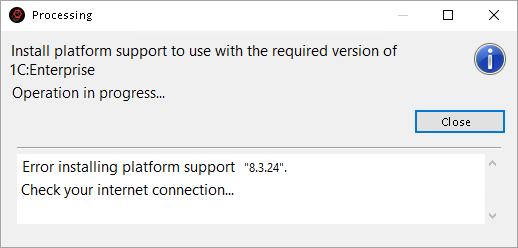
The issue is that the imported project was created in version 8.3.24 of 1C:Enterprise. However, the installed version of 1C:EDT does not include support for this platform version.
This is not an error. To keep the 1C:EDT installation package from being excessively large, it includes support only for the latest versions of the 1C:Enterprise platform. If support for a missing version is required during use, 1C:EDT can automatically download and install the necessary files. This is what 1C:EDT is attempting to do in this case.
However, at this point it turns out that the version of 1C:EDT being used does not support the required version of the 1C:Enterprise platform at all. A more recent version of 1C:EDT is required.
To resolve this issue, you need to use a later version of 1C:EDT that, according to system requirements, supports this version of 1C:Enterprise:
-
If you are using 1C:EDT Start, change the development environment release for your project.
-
If you are using the offline installation package:
Infobase Creation Failed
When importing a project from a Git repository, you may encounter the following error:
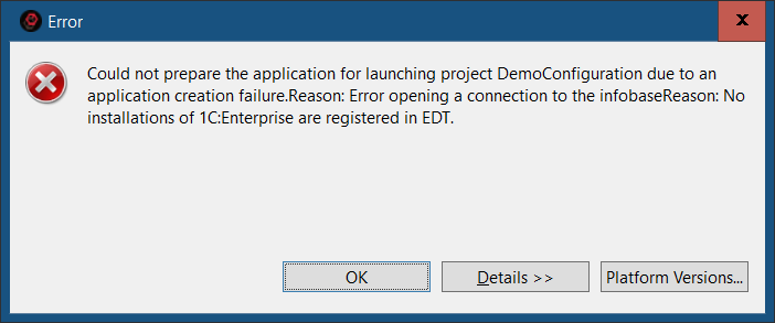
If you click Details, select Copy in the context menu, and paste the result into any text editor, you will see the following message:
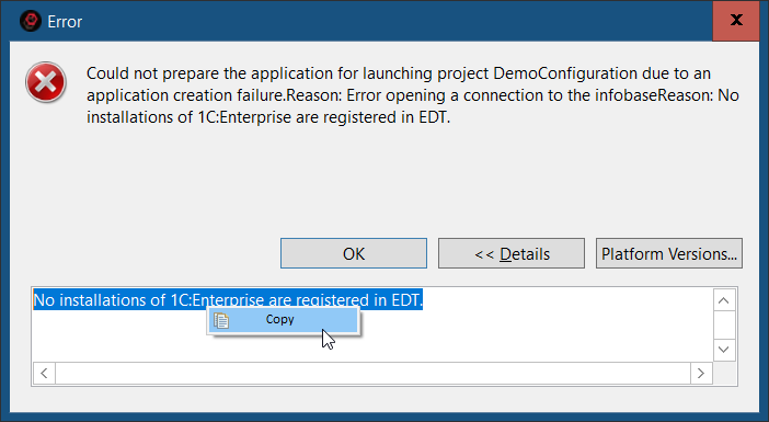
No registered platform versions matching the version mask "8.3.24" were found. It is possible that the required versions are installed on the system but are not registered. To check the list of registered platform versions, click the "Platform Versions..." button.
The issue is that the infobase is being created for a project that requires version 8.3.24 of 1C:Enterprise. However, this platform version is not installed on your computer.
To resolve this issue, you need to install the required version of 1C:Enterprise.
Error Publishing to Web Server Cause: Access Error to the File httpd.conf
The error log contains an entry like this:
Caused by:
com._1c.g5.v8.dt.platform.services.core.publication.WebServerAccessException:
java.nio.file.AccessDeniedException:
C:\Program Files (x86)\Apache Software Foundation\Apache2.2\conf\httpd.conf
Most likely, the reason is that after creating the publication, 1C:EDT was unable to restart the web server.
For 1C:EDT to restart the web server, it must be run as an administrator of the operating system. In Windows Vista and later, it is not enough that the user running 1C:EDT is in a group with administrative privileges.
To fix this issue, manually restart the web server using its built-in tools.
To avoid this situation in the future, run 1C:EDT as an administrator. You can do this by right-clicking Run as administrator in the context menu of the 1cedt.exe file in Windows Explorer.
Conditions for successful interaction with the web server in Linux can be found here.
A Platform Version of at Least ... Is Required to Interact with the Configuration
This error may occur, for example, when starting the application or updating the configuration in the infobase.
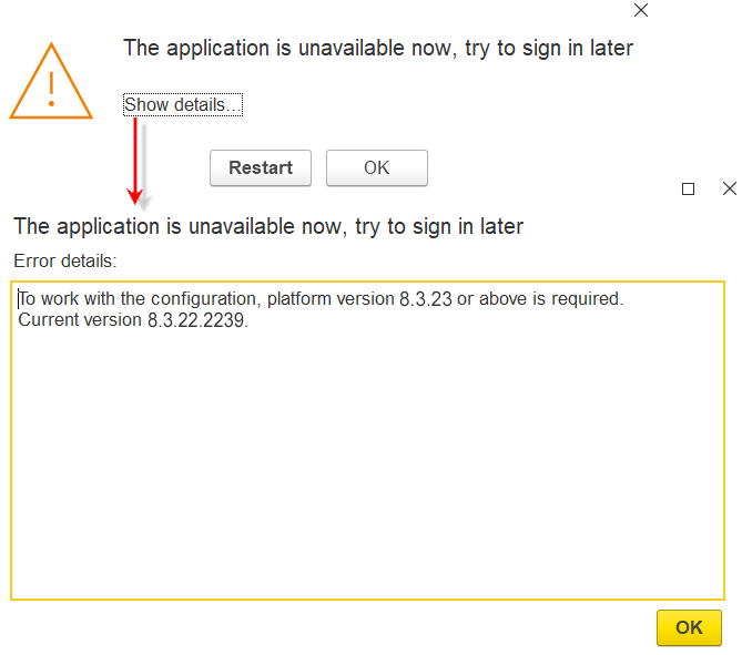
The reason is that the platform version specified in the project settings (in this case, 8.3.13) is lower than the platform version used to create the configuration in the infobase (in this case, 8.3.14).
The only possible solution in this situation is to select a different infobase for interaction with the project. One where the configuration was created with version 8.3.13 or earlier.
After Execution, No Users With Administrative Privileges Would Remain!
This error may occur, for example, when starting the application or updating the configuration in the infobase.
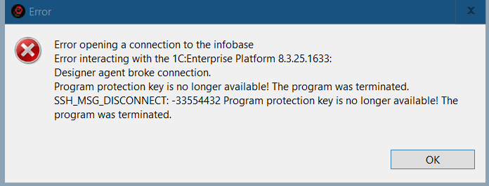
At this point, 1C:EDT has loaded the configuration from the project into the main configuration of the infobase and is attempting to update the database configuration. The issue is that there is a user in the infobase with a role that grants full rights. However, after the upcoming database configuration update, this role will be removed. This means that no user will be able to perform administrative actions. Such a situation is unacceptable.
The reason is that the role granting administrative privileges in the project configuration differs from the role granting administrative privileges in the infobase configuration (they have different internal identifiers).
In this case, you can take one of two approaches:
-
Choose a different infobase to interact with this project.
-
Delete users in the infobase.
To delete users in the infobase and retry the operation, follow these steps:
-
Launch 1C:Enterprise Designer from 1C:EDT.
-
Delete the infobase users and close Designer.
-
In the infobase access settings, clear the fields Username and Password.
-
Repeat the operation you were performing.
Performance Degradation in Disk Operations
When using 1C:EDT on terminal servers (via Windows RDS) or directly on a Windows computer, significant performance degradation in disk operations may occur in some cases. For example, during Git repository cloning, full project builds, or comparing a project with a Git branch.
One possible cause is the Disk Fair Share feature enabled in the RDS service. Its purpose is to prevent excessive disk usage by a single user by evenly distributing disk I/O operations across sessions.
In some operating systems, such as Windows Server 2019, this feature is enabled by default, while in others (Windows 10 Enterprise, Windows 11 Enterprise), it is disabled by default.
If you experience disk performance issues, we recommend disabling Disk Fair Share. To do this, run the following commands:
$temp = (gwmi win32_terminalservicesetting -N "root\cimv2\terminalservices")
$temp.enableDiskFSS = 0
$temp.put()
More details: