1C:Enterprise 8.3 Developer Guide
Contents
-
Chapter 2. Managing configurations
- 2.1. General information
- 2.2. Opening configurations
- 2.3. Saving configurations
- 2.4. Closing configurations
- 2.5. Saving configurations to files
- 2.6. Loading configurations from files
- 2.7. Configuration object tree
- 2.8. Metadata tree sort setting
- 2.10. Property palette
- 2.11. "More" window
- 2.12. Object editing window
- 2.13. Creating the help section
- 2.15. Starting 1C:Enterprise
- 2.16. Exporting and importing configuration files
- 2.18. Configuration extensions
- 2.19. Operations with the mobile client
- 2.20. Configuration report
- 2.21. Global search and replacement
- 2.23. Saving the configuration ID to a file
- 2.24. Operating with configurations using 1C:Enterprise language
-
Chapter 4. 1C:Enterprise language
- 4.1. Purpose and brief description of 1C:Enterprise language
- 4.4. Assignment statement
-
4.7. Working with queries
- 4.7.1. Accessing object properties
- 4.7.2. Extending the context of objects and forms
- 4.7.3. Serialization/deserialization
- 4.7.4. Passing procedure and function parameters
- 4.7.5. Using value collections
- 4.7.6. Using numbers and indexes
- 4.7.7. Using system enumerations
- 4.7.8. Operations with predefined values
- 4.7.9. Synchronous and asynchronous operations
- 4.7.10. Converting values when changing the type
-
Chapter 5. Configuration objects
- 5.2. Managed application module
- 5.3. External connection module
- 5.4. Session module
-
5.5. "Common" configuration branch
- 5.5.1. Subsystems
- 5.5.2. Common modules
- 5.5.3. Session parameters
- 5.5.4. Roles and access rights
- 5.5.5. Common attributes
- 5.5.6. Exchange plans
- 5.5.7. Filter criteria
- 5.5.8. Event subscriptions
- 5.5.9. Scheduled jobs
- 5.5.10. Functional options and functional option parameters
- 5.5.11. Type collections
- 5.5.12. Settings storages
- 5.5.13. Common forms
- 5.5.14. Common commands
- 5.5.15. Command groups
- 5.5.16. Common templates
- 5.5.17. Common pictures
- 5.5.18. XDTO packages
- 5.5.19. Web services
- 5.5.20. HTTP services
- 5.5.21. WS references
- 5.5.22. Styles and style elements
- 5.5.23. Languages
-
5.6. Common configuration object properties
- 5.6.1. General properties
- 5.6.2. Metadata object presentation
- 5.6.3. Arbitrary data presentation
- 5.6.4. Standard attributes
- 5.6.5. Predefined data
- 5.6.6. Objects numeration
- 5.6.7. Input by string
- 5.6.8. Table
- 5.6.9. Forms
- 5.6.10. Commands
- 5.6.11. Feature for filling new object attributes
- 5.6.12. Checking attribute filling
- 5.6.13. Indexing object attributes
- 5.6.14. Rights
- 5.6.15. Quick choice
- 5.6.16. Choice history on input
- 5.6.17. Creating new items on input
- 5.6.18. Choice parameter links
- 5.6.19. Choice parameters
- 5.6.20. Other
- 5.11. Enumerations
-
Chapter 6. Command interface
-
6.3. Service options for navigation
- 6.3.1. URLs
- 6.3.2. User Notifications
- 6.3.3. Displaying the status of long-running processes
- 6.3.4. Viewing messages
- 6.3.5. Keyboard shortcuts
- 6.3.6. Form list operations
- 6.3.7. Using the jump list
- 6.3.8. Installing preview window buttons for the Windows taskbar
- 6.3.9. Taskbar overlay icon management
- 6.4. Command interface development order
-
Chapter 7. Forms
- 7.1. General information
- 7.6. Form module
-
7.7. Form items
- 7.7.1. General information
- 7.7.2. General properties of form items
- 7.7.3. Forms
- 7.7.4. Field
- 7.7.5. Decoration
- 7.7.6. Tables
- 7.7.7. Buttons
- 7.7.8. Group
- 7.7.9. Supplementing a form item
- 7.7.10. Special command bars
- 7.7.11. Conditional form appearance
- 7.7.12. Form item behavior
- 7.7.13. Rules for placing form items
- 7.8. Form command interface
-
Chapter 8. Working with queries
- 8.1. General information
- 8.2. Query data (table) sources
- 8.3. Virtual and standard fields
-
8.4. Query language
- 8.4.1. General information
- 8.4.2. Query language syntax diagram
- 8.4.3. Comments in query language
- 8.4.4. Using predefined configuration data
- 8.4.5. Bilingual keyword presentation
- 8.4.6. Main query text sections
- 8.4.7. Query description
- 8.4.8. Selection field description
- 8.4.9. Query source description
- 8.4.10. Temporary table
- 8.4.11. Filtering query results
- 8.4.12. Grouping query results
- 8.4.13. Conditions for aggregate function values
- 8.4.14. Merging queries
- 8.4.15. Ordering of query results
- 8.4.16. Calculating query totals
- 8.4.17. Expressions in query language
- 8.4.18. Conditions in query language
-
Chapter 10. Data composition system
- 10.1. General data composition information
-
10.3. Data composition schema
- 10.3.1. Data composition schema components
- 10.3.2. Using multiple data sets
- 10.3.3. Query language extension for the data composition system
- 10.3.4. Data composition system expression language
- 10.3.5. Data composition schema wizard
- 10.3.6. Setup options of data composition schema
- 10.3.7. Custom settings of the data composition system
- 10.5. Data composition processor
- 10.6. Functional options and report field view rights
- 10.11. Features of using the data composition system
-
Chapter 13. Business processes and tasks
- 13.1. Basic concepts
- 13.2. General part
- 13.3. Routing
- 13.4. Addressing system
- 13.5. Starting business processes
- 13.6. Completing tasks
- 13.7. Separation and merger
- 13.9. Condition point
- 13.10. Switch
- 13.11. Generating tasks
- 13.12. Checking performance
- 13.13. Completing nested processes
- 13.14. Completing business processes
- 13.15. Standard attributes of business processes and tasks
- 13.16. Business processes with multiple start points
- 13.17. Feedback
- 13.18. Flowchart
- 13.19. Editing business process
- 13.20. Editing tasks
-
Chapter 17. Integration with external systems
- 17.1. General information
-
17.4. Standard OData interface
- 17.4.1. General information
- 17.4.2. General principles of operation
- 17.4.3. Data presentation
- 17.4.4. Resource name generation rules
- 17.4.5. Filter condition generation rules
- 17.4.6. Query parameters
- 17.4.7. Ways to get a description of the standard OData interface
- 17.4.8. Ways to get data
- 17.4.9. Executing functions and actions
- 17.4.10. Erroneous situations
- 17.4.11. Setting separator values
- 17.4.12. Publishing the standard OData interface
- 17.4.13. Performing standard operations
-
17.6. External data sources
- 17.6.1. General information
- 17.6.2. Relational external data sources
- 17.6.3. Operating external OLAP data sources
- 17.6.4. Procedures and functions of external data sources
- 17.6.5. Manage external data sources
- 17.6.6. Connecting to external data sources in 1C:Enterprise mode
- 17.6.7. External data source features
-
Chapter 21. Temporary storage functionality, handling files and pictures
- 21.1. Temporary storage
- 21.2. Features of handling files in the asynchronous mode and in the web client
-
21.3. File and temporary storage operation methods
- 21.3.1. General information
- 21.3.2. Migrating file data to the temporary storage
- 21.3.3. Data retrieval from the infobase to the file
- 21.3.4. Data retrieval from the temporary storage
- 21.3.5. Data removal from the temporary storage
- 21.3.6. Checking whether the address is attributed to the temporary storage
- 21.3.7. Retrieving attribute address
- 21.3.8. Authorization to perform a group of file operations
- 21.3.9. Operating temporary storage in the background job
- 21.3.10. Access to standard directories
-
Chapter 23. Cryptographic feature
- 23.1. General information
- 23.2. Basic concepts
- 23.4. Public key certificate
- 23.5. Operation of cryptography modules
-
23.6. Application examples
- 23.6.1. General information
- 23.6.2. Creating an object for access to the cryptographic feature
- 23.6.3. Getting a certificate list
- 23.6.4. File encryption
- 23.6.5. File decryption
- 23.6.6. EDS generation
- 23.6.7. EDS checking
- 23.6.8. EDS enhancement
- 23.6.9. Adding an archive timestamp
- 23.6.10. Getting information on signatures
- 23.7. Asynchronous operation of the cryptographic feature
-
Chapter 25. Data history
- 25.1. General information
- 25.2. Mechanism structure
-
25.3. Using the feature
- 25.3.1. General information
- 25.3.2. Managing data history usage
- 25.3.3. Writing versions
- 25.3.4. Processing after writing history
- 25.3.5. Getting a version list
- 25.3.6. Getting version data
- 25.3.7. Version comments
- 25.3.8. Version deletion
- 25.3.9. Identifying differences between versions
- 25.3.10. Data history and extension
-
Chapter 28. Development for mobile devices
- 28.1. General information
-
28.7. Mobile device interaction during development
- 28.7.1. General information
- 28.7.2. Installing developer tools
- 28.7.3. Publishing a mobile application on a web server
- 28.7.4. Starting and restarting mobile platform applications
- 28.7.5. Application debugging
- 28.7.6. Managing the mobile application for developers
- 28.7.7. Building a mobile application before publishing it to the application store
-
28.8. Mobile Application Builder
- 28.8.1. General information
- 28.8.2. Setting the builder
- 28.8.3. Importing required data
- 28.8.4. Setting the application to be built
- 28.8.5. Building the application
- 28.8.6. Publishing applications
- 28.8.7. Additional features of the mobile application builder
- 28.8.8. Recommendations on how to update build infrastructure
-
Chapter 30. Configuration extension
-
30.4. Extension objects
- 30.4.1. Extension properties
- 30.4.2. Modules
- 30.4.3. Forms
- 30.4.4. Form command interface
- 30.4.5. Object forms
- 30.4.6. Subsystems
- 30.4.7. Access rights
- 30.4.8. Reports and data processors
- 30.4.9. XDTO packages
- 30.4.10. Web services
- 30.4.11. HTTP services
- 30.4.12. Predefined items
- 30.4.13. Spreadsheet document
- 30.4.14. Exchange plans
- 30.4.15. Catalogs
- 30.4.16. Documents and journals
- 30.4.17. Enumerations
- 30.4.18. Session parameters
- 30.4.19. Functional options and functional option parameters
- 30.4.20. Filter criteria
- 30.4.21. Event subscriptions
- 30.4.22. Types in adopted objects
- 30.4.23. Type collections
- 30.4.24. Integration services
- 30.4.25. Common attributes
- 30.4.26. Configuration object properties
- 30.4.27. Templates
- 30.4.28. Numerators
- 30.4.29. Scheduled jobs
- 30.4.30. External data sources
- 30.4.31. Business processes and tasks
- 30.5. Extension and distributed infobase
- 30.6. Security profiles
- 30.8. Operating with extensions from 1C:Enterprise language
-
Chapter 31. Debugging and testing applications
- 31.1. General information
-
31.2. Debugger
- 31.2.1. General information
- 31.2.2. Using Debugger
- 31.2.3. Breakpoint
- 31.2.4. Step-by-step execution
- 31.2.5. Debugging external data processors (reports)
- 31.2.6. Debug management
- 31.2.7. "Expression" window
- 31.2.8. Immediate window
- 31.2.9. "Local variables" window
- 31.2.10. Variable value change
- 31.2.11. Call stack
- 31.2.12. Debugging protected modules
- 31.5. Server call delay simulation
- 31.6. Server call history
-
Chapter 35. Development tools
- 35.5. Main section command interface editor
- 35.6. Command interface editor
- 35.8. Query wizard
- 35.9. Query wizard with result processing
- 35.10. Register record wizard
- 35.11. Print wizard
- 35.12. Generation settings wizard
- 35.14. Template wizard
- 35.15. Format string wizard
- 35.16. Wizard for strings in different languages
- 35.21. Configuration localization
- 35.22. Centralized configuration verification
-
Chapter 36. Comparing and merging configurations
- 36.1. General information
- 36.2. Configuration comparison conditions
- 36.3. Starting the configuration comparison and merging mode
- 36.4. Comparing configurations
- 36.5. "Compare and merge configurations" window
- 36.7. Editing objects
- 36.8. Editing features of distributed development and support
- 36.9. Mapping objects
- 36.11. Subordinate object order setting
- 36.12. Viewing differences
- 36.13. Comparing and merging modules
- 36.14. Selecting objects and starting the merging
- 36.15. Loading configurations from files
-
Chapter 37. Distributed configuration development
- 37.1. General information
-
37.3. Operating configuration repository
- 37.3.1. Repository filter
- 37.3.2. Locking repository objects
- 37.3.3. Storing objects in repository
- 37.3.4. Retrieving objects from repository
- 37.3.5. Unlocking objects
- 37.3.6. Updating status of repository objects
- 37.3.7. Comparing repository with current configuration
- 37.3.8. Comparing a repository object with a current configuration object
- 37.3.9. Saving repository as configuration
- 37.3.10. Disconnecting from repository
- 37.3.11. Repository history
- 37.3.12. Object history
- 37.3.13. Performing actions with configuration repository without connection
-
37.4. Working remotely with configuration repository
- 37.4.1. General information
- 37.4.2. Architecture overview
- 37.4.3. Setting up the repository server
- 37.4.4. Configuring a web server to work with the repository
- 37.4.5. Start the repository server
- 37.4.6. Connecting to the configuration repository server
- 37.4.7. Creating a configuration repository
- 37.4.8. Features of remote work with the configuration repository
- 37.5. Recommendations for using repository
- Appendix 2. Rules of generating standard command texts and automatic form headers
- Appendix 4. Full-text search expressions
- Appendix 5. Access rights description
-
Appendix 6. System behavior specifics in different modes
- 6.1. Slow connection mode specifics
-
6.2. Compatibility mode specifics
- 6.2.1. Previous versions
- 6.2.2. With version 8.3.5
- 6.2.3. With version 8.3.6
- 6.2.4. With version 8.3.7
- 6.2.5. With version 8.3.8
- 6.2.6. With version 8.3.9
- 6.2.7. With version 8.3.10
- 6.2.8. With version 8.3.11
- 6.2.9. With version 8.3.12
- 6.2.10. With version 8.3.13
- 6.2.11. With version 8.3.14
- 6.2.12. With version 8.3.15
- 6.2.13. With version 8.3.16
- 6.2.14. With version 8.3.17
- 6.2.15. With version 8.3.18
- 6.2.16. With version 8.3.19
- 6.2.17. With version 8.3.20
- 6.2.18. With version 8.3.21
- 6.2.19. With version 8.3.22
- 6.2.20. With version 8.3.23
- 6.2.21. With version 8.3.24
- 6.2.22. With version 8.3.25
- 6.2.23. With version 8.3.26
- 6.3. Extension compatibility mode specifics
- 6.4. Web client specifics
- 6.5. Web client specifics on iPad
-
6.6. System object specifics in the data separation mode
- 6.6.1. Changing separator values
- 6.6.2. Objects numeration
- 6.6.3. Real-time timestamp
- 6.6.4. Predefined data
- 6.6.5. Access rights
- 6.6.6. Users
- 6.6.7. Exchange plans
- 6.6.8. Functional options
- 6.6.9. Scheduled jobs
- 6.6.10. Background jobs
- 6.6.11. Web services
- 6.6.12. Constants
- 6.6.13. Registers
- 6.6.14. Document sequence
- 6.6.15. Infobase parameters
- 6.6.16. Session list
- 6.6.17. Connection list
- 6.6.18. Event log
- 6.6.19. Settings and favorites
- 6.6.20. History
- 6.6.21. Standard OData interface settings
- 6.6.22. Queries
- 6.6.23. Managed transaction locks
- 6.6.24. Exclusive mode
- 6.6.25. Delete marked objects
- 6.6.26. Full-text search
- 6.6.27. Configuration extension
- 6.6.28. Data history
- 6.6.29. Collaboration system
- 6.6.30. Integration service
- 6.6.31. Password policies
- 6.7. Client application specifics on Linux
- 6.8. Client application specifics on macOS
- 6.9. Mobile 1C:Enterprise version specifics
- Appendix 9. Specifics of some tools
- Appendix 10. Rules of automatic form item names generation
- Appendix 12. Namespace prefixes in JSON serialization
Introduction
This book is a guide for 1C:Enterprise application developers.
This document is intended for professionals involved in the development, modification, and implementation of applications on 1C:Enterprise platform.
Overview
The Guide describes the general concept of 1C:Enterprise, as well as operations with application objects, form creation, command interface, and the use of 1C:Enterprise features.
Chapter 1 contains the concept of 1C:Enterprise: its general principles, general operation logic, and so on.
Chapter 2 describes the operation with the configuration: how to edit configuration properties, copy configuration objects, save the configuration, merge configurations, operate in auxiliary mode.
Chapter 3 describes the application interface and structure.
Chapter 4 contains general information about 1C:Enterprise language, a description of the used data types, operators, syntactic structures, and the main operations with 1C:Enterprise language.
Chapter 5 describes the main configuration objects and their features.
Chapter 6 describes the command interface and its development logic.
Chapter 7 describes forms, form components, and form operations using 1C:Enterprise language.
Chapter 8 describes the query language and the main operations with queries in 1C:Enterprise language.
Chapter 9 describes the general principles and features of data processing in 1C:Enterprise.
Chapter 10 describes the data composition system.
Chapter 11 describes accounting processes in 1C:Enterprise.
Chapter 12 describes operations with periodic calculations used in 1C:Enterprise.
Chapter 13 describes business processes and tasks.
Chapter 14 describes data analysis and forecasting.
Chapter 15 describes the data exchange functionality.
Chapter 16 describes operations with data formats such as: XML (XDTO), JSON, binary data.
Chapter 17 describes functionality of integration with external systems (Internet services, integration services, external data sources, and so on).
Chapter 18 describes additional web client features.
Chapter 19 describes the job functionality.
Chapter 20 describes full-text search in the database.
Chapter 21 describes how to operate with the temporary data storage and use it for file operations.
Chapter 22 describes operations with the event log.
Chapter 23 describes the cryptography functionality.
Chapter 24 describes data separation.
Chapter 25 describes the data versioning functionality.
Chapter 26 describes operations with database copies and Data Accelerator.
Chapter 27 describes functionality of global data search.
Chapter 28 describes the procedure of mobile application development.
Chapter 29 describes the collaboration system.
Chapter 30 describes configuration extensions that are used to enhance an extended configuration without changing it.
Chapter 31 describes configuration debugging and testing.
Chapter 32 describes the add-in attachment functionality.
Chapter 33 contains recommendations for development of cross-platform applications.
Chapter 34 describes other features that are not included in the chapters above.
Chapter 35 describes how to use a form editor, a text editor, a spreadsheet document editor, a flowchart editor, and an image editor.
Chapter 36 describes configuration comparing and merging.
Chapter 37 describes the group development of configurations.
Chapter 38 describes how to create distribution files, update files, and distribution packages. This chapter will be of interest to replicable configuration developers. This chapter also provides information on how to use distribution and update files for standard configurations that are supported by user configuration developers.
Chapter 39 describes service modes: how to configure Designer settings, use Syntax Assistant, set up templates, use built-in calculator and calendar, compare files, perform operations with windows, and localize 1C:Enterprise configurations.
What you need to know
It is assumed that you are familiar with the operating system of the computer where 1C:Enterprise is installed and that you have basic skills required to work with this operating system.
You must be familiar with the following concepts:
-
Run programs.
-
Use windows.
-
Use the mouse.
-
Operate with texts and spreadsheet documents: enter a text, enter values into spreadsheet document cells, edit, format, and print data, and so on.
-
Use menus.
-
Use dialog box controls.
-
Use standard dialog boxes.
-
Use operating system clipboard.
-
Use appropriate tools to configure the operating system.
If you have not completely mastered these concepts, we recommend that you refer to the operating system documentation.
Agreed notations
Keys. Keys such as Enter, Esc, Del, and others are given without quotation marks.
The Arrow keys phrase is used to specify all arrow keys at once. They are individually referred to as Up Arrow, Down Arrow, Right Arrow, and Left Arrow.
Keyboard shortcuts. When a command requires a keyboard shortcut, it will be denoted as Ctrl + F3. All keyboard shortcuts in the guide are specified for PC-compatible computers. On Apple computers, you need to use Cmd instead of Ctrl and Option instead of Alt in the given keyboard shortcuts. So, the keyboard shortcut Ctrl + Alt + Shift + F5 for a PC-compatible computer will look as follows for an Apple computer: Cmd + Option + Shift + F5.
Buttons. Form buttons are given without quotation marks, like OK, Cancel, Delete, and others.
1C:Enterprise language keywords. 1C:Enterprise language keywords are highlighted by specific font and are given as in modules, for example: WorkingDate. This manual contains references to some parts of 1C:Enterprise language description (sections, methods, attributes, and others). For these descriptions, see the application help (the 1C:Enterprise language section).
Menu actions. Menu interactions are described as follows: Menu – Submenu – Submenu – ... – Menu item. For example: "To select the picture scale, click Table – View – Scale" is similar to: "To select the picture scale, use the Scale menu item of the View submenu in the Table menu in the main menu of the application". If any menu, other than the main menu, is referred, it is specified explicitly.
1C:Enterprise modes. Configuration setup and validation (hereinafter referred to as Designer mode), and configuration execution (hereinafter referred to as 1C:Enterprise mode).
In this manual, the "user" refers to a specialist who develops or maintains the configuration.
The following abbreviations and expressions may be used in this document:
| Expression | Description |
|---|---|
| %ALLUSERSPROFILE% | The %ALLUSERSPROFILE% expression means a Windows environment variable with a directory available to all users. If the operating system is installed using default settings, this path looks as follows: C:/ProgramData |
| %APPDATA% | The %APPDATA% expression means a Windows environment variable that contains a path to the directory (in the user profile) where application data is stored. If the operating system is installed using default settings and the username is Smith, this path looks as follows: C:/Users/Smith/AppData/Roaming |
| %LOCALAPPDATA% | The %LOCALAPPDATA% expression means an environment variable of Windows that contains a path to the directory (in the user profile) where user-specific application data is stored. If the operating system is installed using default settings and the username is Smith, this path looks as follows: C:/Users/Ivanov/AppData/Local |
| %PROGRAMFILES% | The %PROGRAMFILES% expression means a Windows environment variable with a path to the directory that contains data files for applications whose bitness matches the operating system bitness. If the operating system is installed using default settings, this path looks as follows: C:/Program Files |
| %PROGRAMFILES(x86)% | The %PROGRAMFILES(x86)% expression means a Windows environment variable with a path to the directory that contains data files for applications whose bitness does not match the operating system bitness. In other words, this environment variable contains a link to the directory where x32 applications are stored in the x64 operating system. If the operating system is installed using default settings, this path looks as follows: C:/Program Files (x86) |
| %SYSTEMROOT% | The %SYSTEMROOT% expression means a Windows environment variable that contains a path to the operating system installation directory. If the operating system was installed using default settings, this expression equals to C:/Windows |
| %USERPROFILE% | The %USERPROFILE% expression means a Windows environment variable that contains a path to the current user profile directory. If the operating system is installed using default settings and the username is Smith, this path looks as follows: C:/Users/Smith |
| ~/ $HOME | The $HOME expression or ~/ means a Linux or macOS environment variable with a path to the home directory of the user on whose behalf the current operating system session is running. The specific location of the user directory depends on the operating system used. The ~/.1cv8 expression means the.1cv8 directory located in the home directory of the current user. |
| A.B.C.D | For the 1C:Enterprise version, the A.B.C.D expression means that the full version number of the 8.3.24.123 format is to be used. |
| arch | The description of paths to the components of the installed 1C:Enterprise version (on Linux) can use the arch expression. This expression, unless explicitly stated otherwise, describes the processor architecture of the used version, which can take the following values: · arm64. ARM64 processors. · e2kv4. E2K processors. · i386. x86 processors. · x86_64. x86-64 processors. In this case, the path will be described, for example, by the following line: /opt/1cv8/arch/A.B.C.D/conf, and the resulting, actual directory will depend on the system architecture and version. So, for x86 architecture and version 8.3.25.100, the path will be as follows: /opt/1cv8/i386/8.3.25.100/conf. |
All files of the same name that are used simultaneously for Windows OS, Linux OS and macOS, will be mentioned under the same name in this guide, regardless of the OS being used. For example, the 1cestart.cfg file will be stated as is in the guide, as well as on Linux and macOS. However, it will be called 1CEStart.cfg on Windows.
Extensions of executable files are not specified (if any). This means that 1cv8.exe is referred to as 1cv8 in this manual. On Windows, add the .exe extension. On Linux and macOS, do not add anything.
Also, Linux and macOS are case-sensitive, and Windows is not.
Chapter 1. General concepts
1C:Enterprise is a universal enterprise automation platform. It is a development and runtime environment that includes a set of tools, mechanisms, and services that provide everything you need for application development, operation, administration, and maintenance. 1C:Enterprise consists of:
-
The platform, serving as the application development and runtime environment
-
Platform-based applications of different scale and intended for various tasks
-
Methodology of application development
-
Information and technological support for users and developers
Due to its universality, 1C:Enterprise can be used for automation of various economic activities of the enterprise: accounting of goods and material assets, settlements with counterparties, and much more.
1.1. Configurability
Configurability is a major feature of 1C:Enterprise. 1C:Enterprise is basically a set of functionalities designed to manipulate different types of objects of the subject domain. Each 1C:Enterprise configuration determines a set of objects, structures of information arrays, and information processing algorithms that best correspond to the task. A configuration combined with 1C:Enterprise acts as a ready-to-use software product focused on certain types of enterprises and categories of tasks.
Configurations are created and maintained through the regular 1C:Enterprise functionality. A configuration is usually supplied in its standard version, but it can be modified, enhanced by users, or redesigned. 1C:Enterprise provides support for standard configurations.
1.2. Operations
1C:Enterprise operations are divided into two stages: development (description of the subject domain model by means of the application) and runtime (processing of subject domain data).
The development stage includes:
-
Creating structure of the processed information
-
Creating forms for entering initial data and for viewing data lists
-
Organizing storage of the entered and the final information
-
Designing reports and data processors
-
Creating command interfaces for different groups of users
-
Creating the list of users
-
Granting rights to users
The development result is a software product (configuration) representing a subject domain model.
In Designer mode, you can create, edit, compare, and merge configurations.
The development stage deals with documents, document journals, catalogs, attributes, forms, registers, and other universal 1C:Enterprise concepts. The combination of these concepts defines the concept of the application.
The concepts of objects and standard processing operations are defined at the platform level. Configuration tools allow you to describe the structure of data contained in these objects, implement algorithms for data processing, and reflect accounting specifics if necessary.
The data structure is designed in terms of types of subject domain objects (constants, catalogs, documents, registers, enumerations, and so on).
During the runtime stage, 1C:Enterprise uses objects described during the configuration stage (catalogs of goods and companies, invoices, bills, and more).
When in 1C:Enterprise mode, data processing is performed both by regular system tools and by custom algorithms created during the configuration stage.
1.3. Basic concepts
This section describes the basic 1C:Enterprise concepts. This material will be useful for those who are not yet familiar with 1C:Enterprise.
Descriptions of 1C:Enterprise concepts will be accompanied by examples. If you encounter an unfamiliar concept or term, just continue reading: the meaning of the terms used will be explained as you go. Refer to the relevant chapters of this Guide for further details.
1.3.1. The concept of "configuration"
Configuration is the most basic underlying idea in 1C:Enterprise. A configuration is a set of interrelated components:
-
Subsystems
-
Accounting data structure, complete with data input, selection, and print forms
-
Functionality for accounting data recording and calculation of totals
-
Reports and data processors
-
Command interface
-
Roles defining user access rights
-
Common procedures and functions (application module, managed application module, external connection module, session module, and common modules), spreadsheet document templates, and more
-
Auxiliary objects:
-
Functional options and their parameters
-
Settings storages
-
Web tools (Web services, WS references, HTTP services)
-
Auxiliary data (pictures, templates, styles, and so on)
-
Configuration structure is basically a subject domain model. You can create a configuration in Designer. 1C:Enterprise uses configurations to create software environments suitable for certain accounting tasks.
Roles define the privileges of 1C:Enterprise users to access data that is processed by the configuration. The set of privileges granted to a user is generally determined by his or her work duties.
Roles are assigned to users in order to:
-
Restrict the list of users that can access confidential information (a major issue for any accounting system)
-
Prohibit users from performing unsafe operations, such as data deletion or editing, to prevent loss of information
All configuration components are closely interrelated, so that any changes (especially in user rights) need to be consistent.
For example, role assignment can only be performed for existing configuration objects (specific documents, logs, catalogs, and reports). Whenever you add a new object to the configuration structure, this needs to be accompanied by appropriate changes to the role.
Access rights are considered when generating a command interface. If, for example, a user is not allowed to view a catalog, the command to open the list form of this catalog will be removed from the command interface automatically. Access rights are also considered when displaying forms.
1.3.2. Configuration objects
1C:Enterprise configuration object is a formal description of a group of concepts with similar characteristics and the same purpose.
Let us review an example. The Catalog configuration object manages lists of similar data items, such as catalogs, card files, standards lists, and so on. Configuration objects of this type are used to maintain any catalogs required for automation of enterprise activities.
Normally, configuration objects of the Catalog type are digital versions of catalogs actually used in the enterprise, for example, the catalog of employees or goods. However, such objects can also represent lists that have no physical versions.
Note that the configuration object describes not a specific value but the value type only. For example, the Individuals catalog contains no information on any specific person. Instead, it describes a list of attributes, forms for entering attribute values, forms for viewing data lists, and templates for printing the data. In other words, the configuration creates a description scheme that all similar objects of the subject domain must follow. The description scheme in the example above, is applied to all individuals specified in the Individuals catalog.
1.3.2.1. Properties of configuration objects
Each configuration object has its own set of properties. This set is described at the system level and cannot be modified while setting up the configuration. The set of properties of the configuration object is determined mainly by its purpose in 1C:Enterprise.
Name is the main property of any configuration object. When you create a new configuration object, its name is generated automatically. The default name consists of the object type and a number. For example, when you create an attribute, it will be named Attribute1, a document will be named Document1, and so on. You can change this name while editing the properties of the configuration object. The name uniqueness control is automatic. Configuration object name cannot be empty or longer than 80 characters.
If some properties of a configuration object are editable, they can be modified during the configuration stage. The nature of allowed changes and their limits are monitored at the system level. A specialist can achieve the desired behavior of the configuration object by purposefully changing its properties. However, such changes do not affect the basic nature of the object and do not enable it to perform actions that are extrinsic to objects of this type.
Let us review an example.
The Constant configuration object is designed to store information that does not change over time or changes rarely. Previous values of the constant are irrelevant. A simple example of a constant is an enterprise name as it usually does not change during the enterprise lifetime. If you need to access any accounting data values to be changed over time, use an information register without dimensions instead of a constant.
Constants have a large set of editable properties, including:
-
Constant name
-
Synonym
-
Comment
-
Data type
-
Data lock control mode
-
Link that opens the constant manager module
Generally, the constant value (such as enterprise name) is entered only once.
1.3.2.2. Basic types of configuration objects
1C:Enterprise configuration objects are divided into several basic types. Each configuration object type represents the building blocks used to create the configuration.
Formally, configuration objects are grouped into types in the configuration tree. When you open the Configuration window in Designer, available types are listed at the first level of the configuration tree.
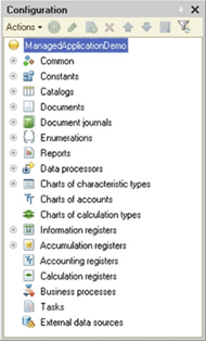
Fig. 1. Metadata tree
Despite the lack of formal definition, names of configuration object types are commonly used by 1C:Enterprise users.
For example, the goal of a specialist configuring 1C:Enterprise is developing a set of catalogs, documents, reports, and logs required to implement an accounting system. The end users of 1C:Enterprise (managers, accountants, storekeepers) use catalogs, documents, reports, and other objects to perform their daily tasks. These two user categories communicate in terms of types of configuration objects.
Each data object is a certain document, report, log, constant, and so on. As a rule, each data object is used to process specific type of information of subject domain.
Basic types of configuration objects in 1C:Enterprise are briefly described below. Detailed information about configuration objects represented by each of these types will be provided further in the chapter.
1.3.2.2.1. Constants
Objects of the Constant type are used in 1C:Enterprise for operations with constant and conditionally constant information. Information stored in constants is rarely changed, but often read. For example, a constant can store the name of a company, its TIN, names of its director and chief accountant, or other similar information.
You can define an unlimited number of constants.
1.3.2.2.2. Catalogs
Objects of the Catalog type are used in 1C:Enterprise for operations with constant and conditionally constant information with a defined set of values.
Generally, catalogs are lists of materials, goods, organizations, currencies, employees, and more.
During the configuration stage, you can describe properties for each catalog. Customizable properties include, among others, length and type of ID codes, number of hierarchy levels, code uniqueness checkbox, and catalog attributes.
In addition to code and name, you can create a set of catalog attributes or tables to store any additional information about a catalog item. For example, for a product, you can specify its purchase and sale prices and its manufacturer. For an employee, you can create such attributes as position, education, residence address, and so on. Tables store data items of the same type whose number may vary. For example, product components, employee's family members, company phone numbers, and more.
Multiple form types can be specified for each catalog: item form, group form, list form, selection form, and group selection form. You can create any number of forms for each form type.
You can use the subordinate catalogs to describe subordinate entities. In this scenario, each item of a subordinate catalog belongs to a certain item of the owner catalog.
In a configuration, you create as many catalogs as you need for storing data on objects used in automation of a given subject domain. For example, you might want to create catalogs for Organizations, Goods, Employees, and so on.
1.3.2.2.3. Enumerations
Objects of the Enumeration type are used in 1C:Enterprise to describe constant sets of values that are not changed during the configuration lifetime.
During the configuration stage, you can define an almost unlimited number of enumeration types. Unlike the catalogs, enumeration values are set during the configuration stage and cannot be changed at runtime.
Typical examples of enumerations include payment types (cash, cashless, barter), customer statuses (regular, one-time), and so on.
A major difference between enumerations and catalogs is that a set of enumeration values never changes while the end user is signed in to the application. Let us review an example where the configuration supports two customer statuses: regular and one-time. In this scenario, the customer status is specified by selecting one of the two enumeration values. Users cannot create new statuses.
Unlike enumerations, users can add new values to catalogs, such as: names of goods, counterparties, and so on.
1.3.2.2.4. Documents
Objects of the Document type are used in 1C:Enterprise to record business events of the enterprise that are related to the automated subject domain. For example, a configuration that was developed to perform accounting of trading operations may contain the following documents: invoices, receipts, delivery notes, and more. You can also use documents to record payments made from the current account, operations on cash accounts, warehouse transfers, or any other events of similar kind.
During the configuration stage, you can define an unlimited number of document types. Typical examples of document types are Payment order, Invoice, Receipt note, Delivery note, Internal transfer note, Cash receipt, and others. Each document type is intended to record a specific event type. This purpose defines its structure and properties in the configuration.
Each document type can have an unlimited number of attributes and tables. Multiple tables are used when you need to register different but related events in a single document, such as: arrival of goods at the warehouse and the incurred additional expenses (transportation costs, handling costs, and so on).
In documents, you can create input forms that digitally represent physical documents. To allow users to include document data into other forms, you can create selection forms. To view a list of documents of the same type, you can create list forms. The number of forms you can create is unlimited. Each document can also have an unlimited number of printed forms.
Each document has a number, date, and time. When you set up a document, you also specify the length of the document number, the number uniqueness check conditions, and more.
Documents play a central role in the core functionality of 1C:Enterprise. All documents form a single chronological sequence. It reflects the actual sequence of events. The sequence of documents with the same date is determined by their respective time stamps. The document time data is used to clearly organize documents with the same date, rather than to record the actual registration time for each document. Data entered into a document (its attributes and tables) usually contains information about an event that has occurred. For example, in an invoice, it might be some goods, their quantity, the warehouse they were shipped from, and additional costs when purchasing the goods.
Posting is a crucial action for any document. If a document is not postable, it means that the event it reflects does not affect the accounting status in the application. When a document is posted, this changes the state of related data. Posting may reflect the document event in configuration registers.
For example, in a trading company, the billing of invoice to the customer does not change the state of the company's goods or funds, as the invoice is only an expression of the customer's intention to purchase the goods. In this case, the Invoice document does not have to be reflected in the accounting registers of this trading accounting application.
However, if the invoice is accompanied by goods reservation for the customer, the Invoice document is reflected in the accounting registers because the invoice transaction also reserves a certain quantity of goods, making them temporarily unavailable. In this case, the accounting application needs to be able to track the reserved items.
1.3.2.2.5. Document journals
Document journals are used to view documents of different types. Each document type can be displayed in several journals. A document journal does not add any new data to the system. It is only a tool for displaying multiple document types in a single document list.
For example, you can create a journal called Warehouse documents that displays all receipt notes, delivery notes, and internal transfer notes.
You can define journal columns to display attributes of different document types assigned to this journal. For example, the Trade Documents journal might contain the Counterparty column that displays the Consignor attribute from the Consignment goods acceptance document, the Company attribute from the Goods receipt note document, and so on.
Each journal can have an unlimited number of visual presentation forms and print forms.
1.3.2.2.6. Reports and data processors
During the configuration stage, you can create an unlimited number of reports and data processors to describe reports and data processing procedures. A report or a data processor can have multiple forms, for example, to enter report generation parameters or data processing parameters. For example, a warehouse selection form might be used to issue a warehouse statement.
The algorithm for getting the report can be described using 1C:Enterprise language or automatically generated by the application if the data composition system is used (see Data composition system). Both text format and a specialized tabular report format (template-based) can be used for reports.
1C:Enterprise also supports development of external data processors that are stored in separate files instead of the application.
1.3.2.2.7. Charts of characteristic types
In 1C:Enterprise, objects of the Chart of characteristic types type are used to describe sets of analytical accounting objects of the same type.
1.3.2.2.8. Charts of calculation types
Objects of this type are used to create types of calculations used in periodic calculation algorithms.
1.3.2.2.9. Charts of accounts
Chart of accounts is one of the basic concepts in accounting. Chart of accounts is a set of synthetic accounts that groups data related to business activities of an enterprise. Data stored in such synthetic accounts provides the user with a complete picture of the state of the enterprise funds in monetary terms.
1.3.2.2.10. Exchange plans
Objects of this type organize data exchange between two infobases or between infobases and external software systems.
1.3.2.2.11. Business processes and tasks
You can create formalized descriptions of typical sequences of operations performed in a company and generate lists of tasks to be performed by an employee at a given time. For example, the process of selling a product item can be represented as a sequence of invoicing, approval, receipt of cash payment, and shipment of the item from the warehouse. Different employees can be responsible for different steps of the process. At any point in time, you can view the current status of the sales process and current tasks of specific employees.
1.3.2.2.12. Registers
Registers store and process data of that reflects economic or organizational activities of an enterprise and is of non-object nature.
Registers usually store information about changes in object states or other information not directly related to the objects of a subject domain. For example, registers can store information about exchange rates or receipt and consumption of goods.
There are 4 types of registers in 1C:Enterprise:
-
Information registers
-
Accumulation registers
-
Calculation registers
-
Accounting registers
1.3.2.2.13. Specialized configuration objects ("Common" branch)
In addition to objects that describe the accounting object domain, a configuration contains secondary objects that are not directly related to enterprise operations, but are closely related to functioning of 1C:Enterprise platform. They include features for user interaction with 1C:Enterprise (command interface, filter criteria, user access rights), auxiliary objects that describe style-based and national language-based formatting; picture libraries, application module, common modules that contain procedures and functions accessible from other configuration modules, common print form templates, and much more.
1.3.2.3. Subordinate object groups
Depending on the configuration object type, an object can have different subordinate groups of objects: attributes, dimensions, forms, tables, and so on. Subordinate objects depend on the object type.
Attributes contain additional information about an object, available only within this object.
Tables are sets of additional information about an object represented as a table.
Note. Attention! The number of rows in a table cannot exceed 100,000.
Table attributes contain table data of an object, available only within this table.
Forms are used to enter, view, and edit information stored in the configuration object. Each form contains a form module in 1C:Enterprise language. Visual presentation enables interaction between the configuration object and users. The nature of such interaction is defined by specialists configuring 1C:Enterprise and determined mainly by the configuration object type. To develop forms, a comprehensive form editor is available in Designer. This editor allows you to edit all form components comprehensively. Each object can have multiple forms.
Commands are used to perform various operations with objects. Commands can be independent or parameterizable.
Templates are spreadsheet, HTML, or text documents (binary and Active documents are also supported) used for quick generation of print forms of an object.
Columns are document journal columns.
Dimensions are configuration objects whose data is recorded in a register.
Resources are data to be recorded in a register.
Groups of subordinate objects cannot be deleted and do not have any editable properties.
1.3.2.4. Typed and type-defining objects
Data type is one of the main properties for some configuration objects. This property determines what kind of information the configuration object can contain. The data type of a configuration object is assigned when you create or edit object properties as part of configuration setup.
Configuration objects that support data typing are referred to as typed configuration objects.
Configuration objects such as Catalog, Document, Data processor are not typed objects because they contain complex information and include typed configuration objects.
Data types supported by configuration objects are divided into two groups.
The first group consists of primitive data types: Number, String, Date, and Boolean. For these types, data stored in a configuration object can be a number, an arbitrary string of characters, a date, or a logical value. NULL, Undefined, and Type are also considered primitive types (for details, see "Primitive data types" in 1C:Enterprise language help).
In addition, some 1C:Enterprise configuration objects can also define data types. For example, you can assign the DocumentRef data type to a constant. In this case, the value of the constant will be a reference to one of the documents stored in 1C:Enterprise.
Configuration objects that can define configuration value types are referred to as type-defining configuration objects in 1C:Enterprise. Such objects include:
-
Catalogs
-
Documents
-
Charts of characteristic types
-
Charts of accounts
-
Charts of calculation types
-
Exchange plans
-
Business processes
-
Tasks
-
Enumerations
Note that type-defining configuration objects define data types as soon as you create an object of any of these types in Designer. This creates three new types: Ref, Object, and List. For example, when you create a new catalog in Designer, new data types appear in the list of data types: CatalogRef.<CatalogName>, CatalogObject.<CatalogName>, and CatalogList.<CatalogName>. These data types can be assigned to any of the typed configuration objects.
Some data can be of a union type. To enable a union data type, select the Union data type checkbox in the data type editing window and specify the types that data can take. You can also select a special type: AnyRef.
When you select an attribute data type, 1C:Enterprise, in addition to selecting the types defined in the application, gives the developer an opportunity to select type sets. Examples of type sets are AnyRef, CatalogRef, Characteristic.<name>, and so on.
Type sets, as well as union data types, contain a list of types defined in the application, but unlike the union type, this list is automatically generated based on metadata analysis.
For example, an application has catalogs named Items and Counterparties. If you have defined an attribute of union data type that includes the CatalogRef.Items and CatalogRef.Counterparties types, you can also define an attribute that contains the CatalogRef type set. In both cases, you can use the attribute to store references both to the Items and Counterparties catalogs.
After adding a new Prices catalog, you can only store references to the Items and Counterparties catalogs in the attribute of union type. However, you can use the attribute described as a type set to store references to any catalogs available in this configuration, including the Prices catalog.
When you start an application, a type set is usually converted to a union type containing all the types to be included in the set. Therefore, in the second case, the new Prices catalog will be included in the type set.
However, a type set is not always converted to a union data type. If a type set only includes one value type, the type set will be converted to that value type. This situation is possible, for example, when a chart of characteristic types (Properties in this example) has a single value type in the CharacteristicsValueType property. In this case, the Characteristic.Properties type set will be converted to the single value type that is defined for the chart of characteristic types, rather than to a union data type that contains one type of value.
This can be important, for example, when you perform a fill check for an attribute whose type is defined as Characteristic.Properties. When Characteristic.Properties is converted to a union data type, the value must be checked for Undefined. When Characteristic.Properties is converted to a specific value type, the default value of that type must be checked.
1.3.3. Command interface
Command interface navigates the user through configuration functionality. The command interface is based on subsystems. The configuration developer adds applied objects to respective subsystems.
Based on the subsystem structure and object distribution between subsystems, the system automatically generates a command interface for the user. The user can view the application structure (hierarchy of subsystems) and run standard commands to access the functionality of applied objects: open catalog lists, view documents, open reports, run data processors, and more. However, the developer can modify the default command interface proposed by the system by changing the order or visibility of commands. To do it, use the command interface editor, which can be called for a particular subsystem or all subsystems.
The commands included in the command interface (opening lists, creating new objects, opening reports, and so on) are provided automatically. However, developers can create their own commands and add them to the command interface.
The purpose of creating a command interface is to ensure that users can access information they need to perform their duties.
1.3.4. Forms
The combination of on-screen dialog box, module, attributes, and commands is called a form.
Most of the configuration objects in 1C:Enterprise can have a visual form. Generally, a configuration object form consists of the following components:
-
On-screen dialog box used to enter and edit information.
-
Form module a program written in 1C:Enterprise language. As a rule, the form module processes information entered into the dialog box for input control, calculations, and more.
-
List of attributes.
-
Commands used in the form.
All of these form components are optional, meaning that none of them are required to contain data.
Forms ensure interaction between the user and applied objects. The nature of such interaction is defined by a 1C:Enterprise application developer. For more information on the form, see Forms.
To edit all form components comprehensively, use the form editor in Designer.
1.3.5. Modules
Module is a program written in 1C:Enterprise language. Modules are located in specific configuration points and are called at predefined 1C:Enterprise runtime points. You can use modules to describe complicated algorithms of configuration objects interaction if visual tools in Designer are insufficient.
There are several types of modules:
-
Managed application module
-
Ordinary application module
-
External connection module
-
Session module
-
Common modules
-
Form modules
-
Modules of configuration objects: constant value managers, catalogs, documents, charts of characteristic types, charts of accounts, charts of calculation types, exchange plans, business processes, tasks, reports, data processors, and register record sets
-
Modules of configuration object managers: catalogs, documents, charts of characteristic types, charts of accounts, charts of calculation types, exchange plans, business processes, tasks, reports, data processors, information registers, accumulation registers, accounting registers, calculation registers, enumerations, document journals, and settings storages
-
Modules of record sets: information registers, accumulation registers, accounting registers, and calculation registers
-
Command modules
To access a module, right-click a configuration object and select Open module.... For a root configuration object, select a managed application module, a session module, an external connection module, or an ordinary application module. Some objects (such as constants or document journals) do not have a module.
For details on modules, see "What is a module?" in the 1C:Enterprise language help.
In objects modules, you can declare variables, procedures, and functions that are accessible using 1C:Enterprise language from outside of the object and supplement the object context. These modules have procedures for handling events, such as generation. They also have procedures for performing object operations initiated outside of the object (for example, printing).
The manager module allows you to extend the functionality of built-in managers by introducing procedures and functions in 1C:Enterprise language. You can describe methods for a configuration object (for example, a catalog) that are related to the actual configuration object instead of a certain database object instance. A manager module cannot have variables or module body.
When functions or procedures of a manager module are declared as exported, you can access them via the object manager:
// Manager module for
the Counterparty catalog. Function
GetDebtorsList()
…
EndFunction
// Call from the
application code. Debtors = Catalogs.Counterparty.GetDebtorsList();1.3.6. Templates
Template is a 1C:Enterprise configuration object used for generation of print forms.
Common templates of print forms are located in the Common templates subbranch of the Common branch of the configuration tree. Print forms of configuration objects (catalogs, documents, document journals, charts of accounts, chart of characteristic types, charts of calculation types, registers, reports, data processors, and other objects) are stored in the subordinate Templates objects, as well as in external files (in this case, the Template spreadsheet document property must be set).
Templates can be of the following types:
-
Spreadsheet document. A standard spreadsheet document is used as a template. To prepare a template, use the spreadsheet document editor.
-
Text document. A text document is used as a template. To prepare a text template, use the text template editor.
-
Binary data. Binary data is used in the template.
-
ActiveDocument. OLE Active document technology is used to create a template. Microsoft Office OpenXML documents cannot be used for ActiveDocument templates.
-
HTML document. HTML document editor is used to create a template.
-
Geographical schema. A geographical schema prepared in the Geographical Schema editor is used as a template.
-
Graphical schema. A graphical schema prepared in the editor is used to create a template.
-
Data composition schema. A data composition schema prepared in the wizard is used to create a template.
-
Data composition appearance template. An appearance template of the data composition system is used to create a template.
-
Add-in. Add-ins used in a mobile or ordinary application are stored to create a template.
1.4. Operating modes, interaction modes, and client application types
1.4.1. Application components
When building an information system on the basis of 1C:Enterprise, a variety of components is used. These components are:
-
Infobase is an integral system which includes at least two configurations (the main configuration and the database configuration), a database, and additional information for operation and administration.
-
Client application is a special program that directly or indirectly interacts with the database to obtain required data. There are several types of client applications and access technologies.
-
1C:Enterprise server (or server cluster) is a program that forms an intermediate layer between 1C:Enterprise client application and the database.
-
Database Management System (DBMS) is a software system that provides management of physical data tables, guarantees their integrity and consistency, and provides access to this data using a special data language.
-
Web server is a software product that receives HTTP requests from clients and passes these requests to respective handlers for execution. If requests come from 1C:Enterprise client application, interaction with a 1C:Enterprise infobase is performed during their processing.
The framework of any 1C:Enterprise-based information system includes one or several of the above components. The information systems can have different operating modes and different types of interaction used by client applications and access technologies.
1.4.2. Operating modes
1.4.2.1. General information
1C:Enterprise supports two operating modes:
-
File mode
-
Client/server mode
In both modes, all applications express completely identical behavior. File mode is primarily intended for personal use and small workgroups. Client/server mode is intended for use in workgroups or at enterprise scale.
1.4.2.2. File mode
File mode of infobase interactions is intended for a single user or a small number of users in the local network. In this mode, all infobase data (configuration, database, and administrative information) is stored in a single file.
This mode ensures easy installation and operation of the automated system. In file mode, infobase operations do not require any additional software. An operating system and 1C:Enterprise are sufficient.
1C:Enterprise file mode provides high infobase integrity and easy backup creation. The user cannot use a wrong infobase file (for example, when copying an infobase) and render the system inoperable.
In addition, backup procedure is very simple. To create a file-mode infobase backup, you only need to copy a single file.
However, despite its ease of use, file mode has certain limitations (see File database). Remember that file mode with web server connection is only recommended for a small number of users, provided that no long-running operations are performed.
1.4.2.3. Client/server mode
Client/server mode is intended for use in workgroups or at enterprise scale. It is implemented on the basis of a three-tier client/server architecture.
The client application interacts with 1C:Enterprise server, which in turn interacts with a supported DBMS. 1C:Enterprise server cluster and a DBMS can be physically located on the same computer or on different computers. This allows the administrator to distribute the load between the servers if necessary.
In client/server mode, the most resource-consuming data processing operations are performed on 1C:Enterprise server cluster. For example, when a client application initiates a complex query, the final query result is sent from the server to the client, while all of the intermediate calculations are executed on the server. Increasing server cluster performance is usually much easier than upgrading all client computers.
Another important aspect of using a 3-tier architecture is easy administration and streamlined user access to the infobase. In this mode, the user does not need to know the physical location of the configuration or database. All access is carried out via 1C:Enterprise server cluster. To access an infobase, the user must enter their username and password to log in to the application and specify the cluster name and infobase name.
Improved data security is another important aspect of the 3-tier architecture. Data is processed by the application server. The client application is only allowed to access the application server and data accessible to the user on whose behalf the client application runs.
Whenever possible, 1C:Enterprise ensures identical behavior of the application for all supported DBMS. Situations when identical behavior cannot be achieved are described in the documentation. Each DBMS is reviewed separately. For more information, see DBMS specifics.
An important feature of client/server mode is the ability to run 1C:Enterprise server and database servers on different operating systems (both Windows and Linux families).
1.4.3. Types of component interactions
To build an information system, all system components must be interconnected, ensuring their interaction. The following interactions between components are distinguished:
-
Direct connection. In this case, the client application connects directly to the database file (in file mode) or 1C:Enterprise server.
-
Connection via a web server. In this case, the client application connects to the web server, and the web server extension performs all further data access activities directly with the database (in file mode) or via the application server (in client/server mode).
-
Mobile platform. It is a special 1C:Enterprise version to be installed on a mobile device running any supported mobile operating system.
An information system often supports multiple access types. For example, the internal network of an enterprise might use a direct connection, while remote users access the same infobase via a web server, and external users can use mobile devices to get the required data.
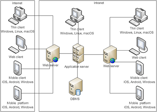
Fig. 2. Component relationships in client/server mode
fig. 2 shows client application connection types in 1C:Enterprise client/server mode.
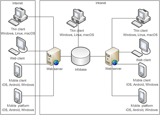
Fig. 3. Component relationships in file mode
fig. 3 shows client application connection types in file mode.
1.4.4. Client application types
Operating modes and access types do not define how the user accesses infobase data.
Various client applications and technologies are used for data access:
-
Thin client is an application that can perform a limited set of actions on a client computer. To perform data operations, the user calls the application server. The majority of actions that create a significant system load are performed on the server side. In thin client, the difference between client and server code is very clear. Developers need to clearly understand where their code will be executed and what it can and must do.
-
Web client is a web application running in a supported web browser. Due to peculiarities of the web browser security model, applications that run in web client have more restrictions than applications that run in thin client.
-
Mobile client is a client application running on mobile devices (iOS, Android, or Windows). The peculiarity of this client application type is that in addition to the standard 1C:Enterprise functionality, it provides access to mobile-specific features: access to camera, location, notifications, and so on.
-
Mobile platform is a special version of 1C:Enterprise designed to run applications on mobile devices on iOS, Android, or Windows. The mobile platform is implemented in the thin client architecture and intended for file infobases located on a mobile device. The mobile platform combined with a configuration form a mobile platform application. The mobile application does not require a permanent connection to any component of the external network infrastructure. If necessary, you can ensure external interactions using a variety of mobile platform tools.
-
Mobile client with standalone mode is a client application managed by mobile operating systems (Android, iOS, or Windows). Such mobile client remains functional when connection to a web server is unstable or interrupted. To be able to operate in standalone mode, you need to configure some extra settings.
You can say that some client applications (thin client, mobile client, mobile application, and thick client) are fully functional on supported operating systems. Web client, however, requires a web browser environment to run.
1.4.5. Interface
Interaction with application users is based on the managed interface. Managed interface is a declarative description of the application interface. Application developers do not specify the exact coordinates of each form item or location of each command in the menu. Instead, they specify location of form items relative to other items, as well as general alignment and grouping of menu commands. Applications that use the managed interface are called Managed applications.
Declarative nature of the interface allows developers to use the same forms with little or no customization in different client applications and on different devices (personal computers, mobile devices).
In the Taxi interface, the managed application (thick, thin, or web clients) supports text display and input in two modes:
-
Left-to-right (LTR). For example, for Slavic and Romano-Germanic interface languages.
-
Right-to-left (RTL). For example, for Arabic interface languages.
Interface is switched automatically if the client application localization language or the current user language must be displayed from right to left.
1.4.6. Ordinary applications
In addition to the managed interface, 1C:Enterprise supports applications that use the regular interface. Regular interface assumes the most precise (up to one pixel) placement of items in the form. When you build a regular interface, you need to manually specify how form items will behave in case of form resizing and where each command will be located in the menu.
Applications that use the regular interface (referred to as ordinary applications) can only be used on a personal computer. These applications cannot be used to access the infobase from web browsers or mobile devices. You can perform operations in ordinary applications only in thick client.
Thick client can perform almost all actions supported by the application. In terms of 1C:Enterprise language, thick client allows operations with the entire list of configuration objects without requiring a server to process the data. In client/server mode, the line between running in thick client and on the server is blurred.
Development of new applications that use the regular interface is strongly not recommended. This technology is only supported for compatibility with earlier application versions.
1.4.7. Summary
To summarize, there are several infobase access methods that depend on the used interface. They are listed below:
-
Managed application:
-
File and client/server access modes.
-
The client application can run on Windows (desktop and mobile), Linux, macOS, iOS, and Android.
-
Access via a web server is available in thin, web, or mobile clients.
-
Mobile devices are supported.
-
-
Ordinary application:
-
File and client/server access modes.
-
The client application can run on Linux, macOS, and Windows (only desktop).
-
Access via a web server is unavailable.
-
Mobile devices are not supported.
-
It is also recommended that you use the managed interface to achieve the maximum lifetime for modern applications in development. The managed interface allows you to build flexible applications compatible with most supported platforms and operating systems. It is strongly not recommended that you use applications with the regular interface or access the application via thick client. These features are only supported for compatibility with previously implemented applications.
1.5. Technological development tools
1C:Enterprise provides several technological tools to describe specific data processing algorithms and create an interface aimed at user-friendly representation of configuration data.
1C:Enterprise language. The need for an embedded language is defined by the concept of system customizability. The 1C:Enterprise language syntax fully meets the standards of high-level languages.
The language is domain-specific. It supports specialized domain data types that are defined by the application configuration. Operations with these data types are organized using object technologies. The language is aimed at users of different proficiency. 1C:Enterprise language is distinguished by soft data typing that ensures fast development of software modules and strict control of syntactic constructions that reduces the probability of errors.
Since 1C:Enterprise includes both visual and language-based configuration tools, the use of 1C:Enterprise language has an event-dependent orientation. This means that language modules are used in specific places to test individual algorithms that are set up during the configuration process. For example, you can create an algorithm for automatic attribute filling when entering a new document. This procedure will be called automatically whenever required.
Query mechanism. To generate arbitrary reports with complex structure, 1C:Enterprise provides a domain-specific query mechanism. This tool relies on the existing conditionally-variable infobase structure, which allows relatively easy description of complex queries.
The built-in text editor is used to create software modules in 1C:Enterprise language and edit text documents.
The editor supports contextual highlighting and grouping of syntactic constructions of 1C:Enterprise language.
Contextual hints and templates make typing code in 1C:Enterprise language faster and easier.
Due to powerful text processing capabilities of 1C:Enterprise language, text format is sufficient to exchange a wide variety of data with other applications.
Built-in form editor. Operations with customizable data structures and operations in Windows interface require custom configuration of forms for entering and editing data. For this purpose, 1C:Enterprise provides a built-in form editor.
You can use it to set up most of the application windows used for entering and viewing data (document forms, catalog forms, and report settings).
Built-in spreadsheet document editor. All output documents (primary documents and reports) are maintained in a uniform spreadsheet format.
Spreadsheet document editor is a powerful tool that combines spreadsheet design capabilities and vector graphics. You can use it both to create small documents with a complex line structure (such as payment order) and long lists, journals, and other similar documents.
The spreadsheet document editor provides users with numerous design features (customizable fonts, colors, lines, and patterns). You can display data in a graphical form (as charts).
The spreadsheet document editor is aimed at report generation using 1C:Enterprise language. Flexible report creation in the editor is achieved due to manipulation of named document areas. In the spreadsheet document editor, you can manipulate both horizontal and vertical areas, which allows you to create reports scalable both in height and in width. By applying editor features in combination with the data composition system, you can create universal reports that allow you to process and present data in different sections and with different details without additional developer intervention.
On the other hand, a spreadsheet document can act as a form control that is used for data entry.
Built-in image editor. The editor allows you to create custom-sized images to use them as toolbar icons, button pictures, and for other design purposes.
Built-in HTML document editor. The editor allows you to create custom descriptions and has extensive design features (hyperlink support, use of styles, placing pictures, and so on).
Wizards are auxiliary tools that facilitate the development of standard 1C:Enterprise components. The application includes, for example, wizards for building forms for constants, catalogs, documents, document journals, reports and other objects, print form wizards, register record wizards, and more.
Wizards are used not only to build visual components of these objects, but in some cases (generation, printing, output forms, and so on) to create the program modules.
User interface customization system. For the interface of a specific configuration to fully reflect configured data structures and algorithms, in addition to the editor of dialog forms and spreadsheet documents, 1C:Enterprise provides customization of the system command interface.
The command interface is automatically modified according to the access rights of the authorized user. The user can view only those application objects they are allowed to access.
Subsystems. In Designer, you can define configuration subsystems (for example, trade accounting and research) during the development stage. For each subsystem, you can specify the configuration objects it includes. You can include an object into multiple subsystems. In fact, subsystems define the main configuration sections the user will deal with. Since the structure of subsystems defines the configuration interface, pay special attention to their design and hierarchy.
System for configuring access rights (roles). This system allows you to describe sets of rights that correspond to user position or duties. The structure of rights is determined in each specific system configuration. For example, you can create such sets of rights as Chief accountant, Storekeeper, Manager, or Head of department.
Besides, you can define access rights for individual fields and records of objects stored in the database (catalogs, documents, registers, and so on).
A list of users is created for each specific organization. Each user is assigned one or more roles, a primary interface, and an application language.
Debugger is available in the application for easy configuration development. The debugger allows you to trace execution of configuration modules, measure comparative execution times, and view the values of variables.
Configuration repository. The configuration repository functionality is commonly used for collaborative configuration development. It allocates access rights to edit configuration objects and make required changes concurrently.
Configuration support. To make configuration updates convenient, developers can use a special tool for creating standard configurations with distribution files and distribution packages (including the installer) and a tool for updating standard supported configurations.
Chapter 2. Managing configurations
2.1. General information
In this chapter, you can read about the general methods for operating with configuration objects of any type. Specific features of creating and editing different types of configuration objects are described below in the respective chapters of this Guide.
This chapter focuses on visual tools used to manage configuration objects that are available in Designer. For the description of 1C:Enterprise language, see its help.
For the information on how to save and restore infobases, see 1C:Enterprise 8.3 Guide. Administrator Guide.
A 1C:Enterprise infobase stores two configurations:
-
Main configuration (editable, hereinafter referred to as "configuration").
-
Database configuration.
The database configuration defines the database table structure and the functionality accessible to users. The main configuration is used only for editing. This allows you to make and save configuration changes without user interruption. You cannot make changes to the database configuration without user interruption. To find out how to operate with the database configuration, see Operations with the database configuration. All main configuration commands (for both main and database configurations) are located in the Configuration menu.
Besides, you can open configuration extension windows in Designer (see Configuration extension). The appearance of a configuration extension window is almost identical to the main configuration editing window. However, actions that the user can perform with the extension configuration are not available from the Configuration menu. The user can only open the extension list (see Configuration extensions) and save the extension configuration (see Saving configurations). You can find extension configuration commands in the Actions – Configuration menu of the configuration extension window or in the context menu of the extension list (see In Designer mode).
Unless otherwise specified, all actions described below are related to the main configuration if they are executed from the Configuration menu in Designer. Commands that are available when managing extensions are related to the respective extensions. These commands are not described separately.
2.2. Opening configurations
Configuration operations are performed in the Configuration window. To open a configuration, click Configuration – Open configuration in Designer menu. The Configuration window will appear on the screen.
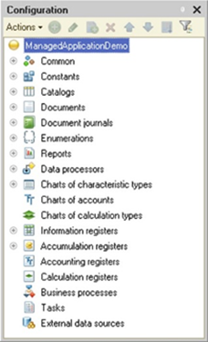
Fig. 4. Configurations
To maximize the work area for operations with multiple objects, you can temporarily close the Configuration window. Closing the Configuration window does not terminate any operations with its individual components open for editing, since the configuration is not closed, only the window. To open the Configuration window, click Configuration – Configuration window in Designer menu.
2.3. Saving configurations
When you edit the configuration, you can create, modify, or delete objects and subordinate objects (forms, attributes and so on). Such changes result in a configuration modification. Modified configurations are marked with an asterisk (*) in the Configuration window title.
To save the configuration, click Configuration – Save configuration in Designer menu. This menu item is only available when the configuration is modified, unlike the text, spreadsheet, and HTML editors where this menu item is always available.
You can save a modified configuration at any moment, even in 1C:Enterprise mode or debugging mode.
This behavior is also applied to the configuration extension window (see Configuration extension).
2.4. Closing configurations
To close the configuration, click Configuration – Close configuration in Designer menu. If the configuration has been modified (changed), Designer displays the following message: Configuration 'Configuration synonym' has been changed. Do you want to save the changes? Click Yes to save your changes.
You can save the changes and close the configuration at any moment, even in 1C:Enterprise mode or debugging mode.
2.5. Saving configurations to files
To save the configuration to a .cf file on the hard drive, click Configuration – Save configuration to file in Designer menu. This will open the standard file selection dialog box. Select a directory and enter the name for the .cf file.
The saved configuration file is required to compare and merge configurations (see Comparing and merging configurations).
Note. Note. If the configuration is supported, the vendor configuration is always stored in the infobase.
2.6. Loading configurations from files
To completely replace the current configuration with the configuration from a .cf file, select Configuration – Load configuration from file in Designer menu.
2.7. Configuration object tree
A configuration is shown as a tree structure, where each branch describes a specific configuration component. Configuration objects are shown under their own names in the configuration tree. For example, the Documents branch contains objects of all documents included in the configuration. The Invoice branch describes the Sales invoice document object. The Common roles branch contains all roles (access rights) used for different types of users. The Manager branch describes access rights for sales managers and so on.
Root branches of the tree contain configuration objects that are logically related and have a common purpose.
For example, the Documents branch contains objects of the Sequences and Numerators types and configuration objects of the Document type. All these objects are used to enter documents in 1C:Enterprise system.
For more convenience, you can use keyboard shortcuts for operations in Designer. You can find the list of available keyboard shortcuts in the built-in help (the Keyboard shortcuts (Designer) section).
You can arrange configuration objects within a group in the order you want. This order will be used to display configuration objects in lists.
To rearrange the order of configuration objects, select an object in the Configuration window and click Actions – Move up, Actions – Move down, or Actions – Sort list.
To find an object that is being edited in the configuration tree (an object editing window, forms, templates, modules), click Edit – Find in tree. Before that, switch to the object editing window. After the command is executed, the object that is being edited will be automatically selected in the configuration tree.
You can search for objects in the metadata tree in several ways:
-
Start typing the object name. The search is only performed in the expanded tree branches.
-
Use the standard search: press Ctrl + F, type the object name, and click Find. This will open the Search results window from which you can navigate to the required metadata object.
-
Use the search field located between the object list and the configuration window command bar. To go to this field in Designer, press Ctrl + Alt + M. To start searching, enter two or more non-space characters in this field. The search scope includes the Name, Synonym, and Comment properties of the configuration objects. The search is performed by the first occurrence of the entered string (see fig. 5). Only the configuration objects that match the entered string are displayed in the configuration tree. All the other objects are hidden.
When the filter is enabled, pressing ESC clears the input field and cancels the search if the input focus is in the configuration tree or the search field. To navigate between the configuration object tree and the search field, press TAB.
If the user adds an object that does not match the filter, the filter will be canceled and the entire configuration tree will be displayed.
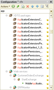
Fig. 5. Search in the configuration tree
You can drag names of configuration objects and subordinate objects (attributes, tables, forms, and so on) into modules and text documents using the mouse.
2.8. Metadata tree sort setting
This mode is used to sort configuration objects. You can sort configuration objects of the same type that are subordinate to the same configuration object at a time.
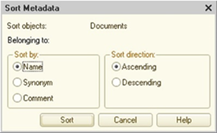
Fig. 6. Metadata sorting
For example, you can sort forms of a specific catalog.
-
Sort by allows you to select a property to sort by:
-
Name. Sort by configuration object names.
-
Synonym. Sort by configuration object synonyms.
-
Comment. Sort by configuration object comments.
-
-
Sort direction allows you to select a sort direction:
-
Ascending. Sort in the ascending order.
-
Descending. Sort in the descending order.
-
2.9. Creating and deleting configuration objects
2.9.1. Creating configuration objects
You can manage most configuration objects in the Configuration window. In this section, you can read about the general methods for creating configuration objects of any type.
To create a new configuration object:
-
In the configuration tree, select a name of the desired configuration object type.
-
In the Configuration window, select Actions – Add.
To create a new subordinate object:
-
Open the object editing window. To do it, in the Configuration window, click Actions – Change.
-
Specify the desired type of the subordinate object.
-
Click Add.
After that, a new object will appear on the current branch of the configuration tree and the property palette will be automatically displayed to edit the object properties (see Property palette). For objects with multiple editable properties, the editing window might be displayed in addition to the property palette (see Object editing window).
The new configuration object is assigned a conditional name. It contains the object type and the object sequence number. For example, when you create a new catalog, its name will begin with "Catalog." The object property palette will contain default property values.
Designer examines object names before updating the database configuration and generating a delivery package.
For objects that can have subordinate objects (for example, a catalog can have attributes, tables, forms, and templates), create the required subordinate objects with the necessary content. To create and set up subordinate objects, you can use various Designer tools.
To simplify the creation of some object components (queries, printing procedures and templates, register records, generation) in Designer, use various wizards (for details, see Development tools).
For objects that can contain forms, Designer offers form wizards that make it easier to design object forms. Form wizard is started when you create a new form (see Configuration object form wizard).
To edit forms, use the form editor (see Form editor).
To edit templates that are based on a spreadsheet document, use the spreadsheet document editor (see Spreadsheet document editor). To create templates, you can use the Print wizard (see Print wizard) and the output form wizard.
To edit templates that are based on a text document, use the text document editor (see Editing text templates).
To create applications in 1C:Enterprise language located in modules, use the text editor (see Editing modules).
To create a new object, you can drag objects using the mouse. When you drag an object and drop it inside or outside of its branch, a new object is created. Designer automatically checks whether source object properties can be copied to the new object. If the new object supports the properties, they will be copied. An example of successful copying is transferring attributes and catalog templates to a document. When you copy the same catalog to an object of the Style type, only the name, the synonym, and the comment will be copied.
When you drag a source object containing subordinate objects (attributes, forms, templates, and so on) to the same level (for example, you drag the Catalog.Currencies object to the Documents branch), the attributes, forms, templates, and tables are copied. However, some properties can be changed. For example, the Parent property is unavailable for documents.
2.9.2. Deleting configuration objects
To delete a configuration object, select it in the configuration tree and click Actions — Delete in the Configuration window. If no references to the object are found in other configuration objects, the object is deleted.
If there are references to the object (it is in use), the following message is displayed: The object cannot be deleted because other objects contain references to it. The message window displays a list of objects using this object.
In fig. 7, you can see a message window that is displayed when you try to delete the GoodsReceipt document.
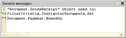
Fig. 7. Service messages
To navigate to an object that contains a reference to the object to delete, double-click the object name in the message window.
Depending on the Check modules before deletion option (for details, see Overall), when you delete a configuration object, all configuration modules will be checked for references to the object. If this check detects that the object is referenced in any 1C:Enterprise language text, a list of reference instances will be displayed and you will be prompted to confirm the object deletion.
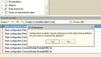
Fig. 8. Checking whether the object is referenced in modules before deletion
To delete a configuration object (search for references to the object to delete), use the configuration search index. In addition to object deletion, the same index facilitates finding configuration object references and renaming objects. The time required to generate a search index depends on the configuration size and can be substantial. So, the index is built in the background when Designer is idle (meaning no user actions are being performed). If the index is only partially built when needed, the system will first complete its building and then perform the requested operation.
Between sessions, Designer saves the built index to the hard drive and reads it upon startup. The index is read in the background, allowing you to start and use Designer without any delay. If you do not need background index building, you can disable it by adding the /DisableBackgroundIndexBuild command to the Designer startup command line. The index will then be built when needed. The command will resume after the index is built.
See also:
- Startup command line of Designer.
2.9.3. References to configuration objects
Some configuration objects contain no references, for example, the Purchase price attribute of the Number type. Other objects contain references to other objects. For example, the Unit of measure attribute of the Products catalog refers to the Units of measure catalog.
You might need to know configuration objects that refer to a given object or are related to it. To find this information, in the Configuration window, click Actions – Find references to object or Actions – Find references in object. The search for references uses the search index. For more information on search index, see Deleting configuration objects.
This opens a dialog box (see fig. 9).
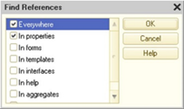
Fig. 9. References to object
In the dialog box, specify the search area (properties, subordinate objects) and click OK.
If any references are found, the message window will display the list of found references. If no references are found, one of the following messages will be displayed:
-
There are no references to this object
-
References not found in object
To display a list of all the aggregate types that are used in the object, click Actions – Find references in object.
To open the reference, double-click the respective line with the reference object name in the message window.
2.10. Property palette
When you edit a configuration object, you change its properties to create the desired behavior.
Property palette is a window containing a set of properties that can be defined for a configuration object. The list of properties may vary depending on the type of object you are editing.
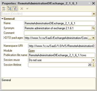
Fig. 10. Property palette
In this section, you can read about the general methods for using the property palette.
To call the property palette, select a configuration object and click Edit – Properties in Designer menu.
In the property palette, object properties are grouped by category. The number of categories and the list of properties in each category may vary depending on the object type. For example, the property palette for a document attribute contains only the General, Use, and Presentation categories. The list of category properties also varies depending on the object type. Even for objects of the same kind, available properties are determined by individual object settings. For example, for a hierarchical catalog, the tabular field properties of the Use category include the Presentation, Show root, and other properties.
The list of properties also depends on the selected values of other properties. For example, if you select the primitive Number type in the Type property, the following properties that characterize the selected type are added: Length, Precision, and Nonnegative.
To quickly find a property in the property palette, use the search field. To open the field, press Ctrl + Alt + I. The search is performed by the properties presentation in the property palette (see fig. 11). To start searching, enter two or more non-space characters in the field. To clear the search field, click the clear button or press ESC in the search field.
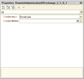
Fig. 11. Search in property palette
The property palette tools panel contains five buttons (see fig. 12). The first three buttons control how the properties are displayed.
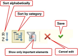
Fig. 12. Property window buttons
The buttons are:
-
Sort alphabetically. If the button is enabled, it displays object properties sorted alphabetically. The property categories are hidden. If the property name display is enabled, properties are sorted by name. Otherwise, properties are sorted by the presentation. If the property does not have a name, properties are always sorted by the presentation. The property name display is controlled by the Display property names item in the property window context menu.
-
Sort by categories. If the button is enabled, it displays object properties sorted by categories.
-
Show only important elements. If the button is enabled, it displays only important object properties. If the button is disabled, it displays all properties.
-
Cancel editing. Cancels all changes made to the property text field.
-
Save. Saves changes made to the property text field.
Property categories can be displayed as tabs or as a list. When you choose to view properties as a list, the properties can be displayed by category or alphabetically (category names are not shown).
To select a category display method, open the context menu in the property palette window and select a display method: Tabs or List. You can select a display method only when the category display is enabled, meaning the Sort by categories button is enabled. If you select the Tabs display mode, the Sort alphabetically and Sort by categories buttons become unavailable.
To switch to properties of another category in the Tabs display mode, click the respective tab.
To return to the List display mode, open the context menu property window and click List.
If you select the List display mode, object properties are arranged by categories or alphabetically. To arrange properties alphabetically, click Sort alphabetically in the property palette tools panel. All properties are displayed in the alphabetical order.
To sort properties by categories, click Sort by categories in the property palette tools panel. All properties will be grouped by categories into a vertical list. Category names are highlighted in bold. To the left of each category name, you can find a button to expand or collapse the category. The button hides or shows all properties in the category.
Double-click a property category name to expand the given category properties and collapse all the other categories.
If you click Show only important elements, only important (main) object properties are displayed regardless of the display mode: a list or tabs, by category or alphabetically. To view all properties, click Show only important elements again.
Depending on the object kind, its properties can or cannot be editable. For example, object properties of a text document are used only to display the number of lines and characters and the document status but they are not editable.
Each property in the property palette has a name and a detailed description. To set the detailed description mode, right-click the property palette (outside the input fields) and select Note. If this mode is enabled, a detailed description is displayed at the bottom of the property palette when a property is selected. Besides the description, a property name used to access the value from the module can be displayed.
Properties that you can access using 1C:Enterprise language tools can be displayed as property names or descriptions. For example, a property can have the Value type description and the ValueType name. To change the display mode, click Display property names in the context menu. Property names are displayed according to the selected 1C:Enterprise language option.
Note. IMPORTANT. Property names of metadata objects and the Configuration metadata object are not displayed.
A method to enter values in the property palette depends on the type of the property you are editing.
Fig. 13. Possible actions
To enter values for text attributes, type a text or copy it from the clipboard. To enter values for the "checkbox" properties, click them. Some property values are selected from lists. The fields of these properties have a selection list button (see fig. 13). If a property field has a selection button (see fig. 13), you can click it to open a window to select a property value or to view it when an object is not editable. For example, when an object is not stored in the configuration repository or supported with no editing features. These properties include picture file selection, color definition, and so on.
For text data, the View button (see fig. 13) opens the line editing dialog box in different languages. For events, it opens the form module procedure that handles the event. For properties from the Presentation category, it opens the existing data object form. The Clear button (see fig. 13) clears the value of the specified property. The Adjustment button (see fig. 13) increases or decreases the numeric value of the field by 1.
A field can have multiple buttons.
When you start editing a text field in the property palette, the Cancel editing (see fig. 12) and Save (see fig. 12) buttons of the property palette tools panel become available. To cancel the changes, click "Cancel editing". To save the changes, click "Save".
The property palette can contain references that open forms related to the selected object. For example, you can open the help (description) for a configuration object, forms, and procedures of the form module. These references are underlined. To open a window related to the reference, click the reference.
If you view the properties of a read-only object (for example, an object that is not stored in the repository, see Distributed configuration development), the type editing dialog box is opened in view-only mode.
2.11. "More" window
You can use the More window to view and modify the main interface properties of a configuration object. To open it, click Edit – More in Designer menu.
To view properties, select an object in the Configuration window. Its properties will be shown in the More window.
The information in the window is grouped into tabs.
You can include metadata objects in subsystems regardless of the mutual subordination of the subsystems. You can include an object both in the parent and the subordinate subsystems at the same time. To do this, go to the Subsystems tab.
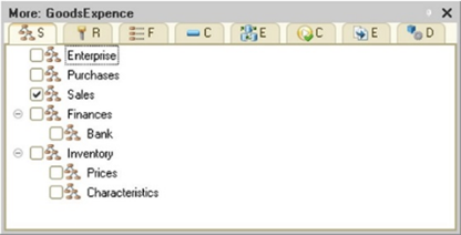
Fig. 14. "Subsystems" tab
The Rights tab contains roles and role rights for the object.
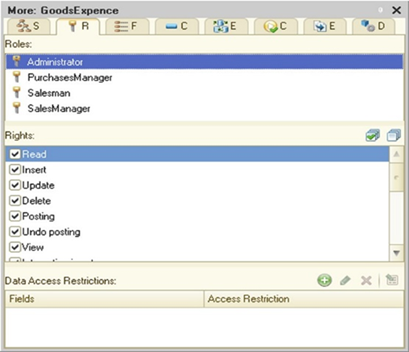
Fig. 15. "Rights" tab
In the Data access restrictions tabular field, you can restrict access to specific data at the level of individual fields and records. For more information, see Data access restriction.
The Functional options tab contains functional options available in the application. You can check functional options this metadata object is linked to.
Fig. 16. "Functional options" tab
The Common attributes tab allows you to specify common attributes the object belongs to. Editing rules in this window are the same as in the Content window of the common attribute property.
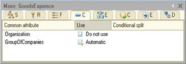
Fig. 17. "Common attributes" tab
The Exchange plans tab contains exchange plans. Exchange plans used to record changes made to the object are marked in the list.

Fig. 18. "Exchange plans" tab
The Command interface tab allows you to edit the visibility of standard and custom commands for the selected metadata object broken down by different subsystems. The commands displayed on the home page are grouped in the Desktop node.
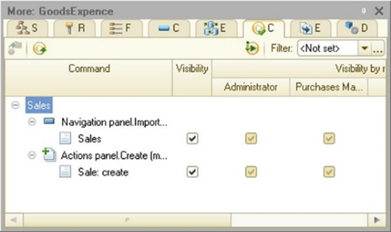
Fig. 19. "Command interface" tab
The Enter based on tab contains objects used to enter the given object and objects used as the basis for exchange plans.
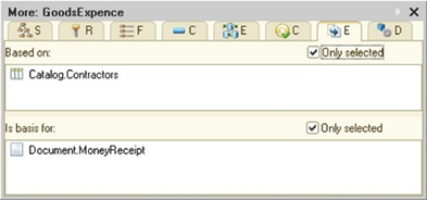
Fig. 20. "Generation" tab
Select the Selected only checkbox to display only selected objects or all objects that can be entered on the basis where the selected objects have check marks.
The Delivery settings tab allows you to select a delivery rule for the selected configuration object, similar to the delivery settings dialog box (see Distribution settings).
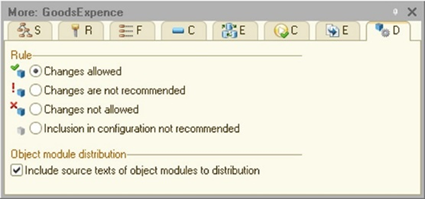
Fig. 21. "Delivery settings" tab
2.12. Object editing window
In the object editing window, you can edit object properties, manage subordinate objects, set up object interaction for the main configuration objects (catalogs, documents, document journals, and so on).
To open the object editing window, in the Configuration window, click Actions – Change.
Editable properties are located on several tabs. Each tab contains a set of attributes for setting up properties of objects of a certain type. For example, on the Main tab, you can enter the Name, Synonym, and Comment properties. On the Subsystems tab, you can specify subsystems where the object is used. To navigate through the tabs, click Next > and < Back. You can also select the required tab with a mouse pointer. The form has the Actions button that displays the object context menu. Use the commands in this menu to open a form or an object module (if any), to start a wizard, and perform other actions.
Tabs and controls on each tab may vary depending on the type of the configuration object.
For example, the editing window for the Catalog object looks as follows:
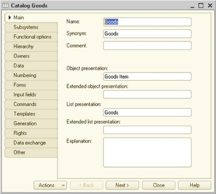
Fig. 22. "Main" tab
On the Main tab, you can specify the Name, Synonym, and Comment properties. On this tab, you can also specify properties used to generate an object presentation in the command interface (for details, see Metadata object presentation).
If you change an object name by editing the Name property, Designer searches for occurrences of the old name in the configuration. The search is performed in string constants, queries (including the data composition system and dynamic lists), and data access restriction texts. The search for references uses the search index. For more information on search index, see Deleting configuration objects.
The search detects cases when the old name is used and the fact of use does not need to be clarified. For example, the program code has the Catalogs.Products construction when you rename this catalog. The search also detects cases of possible use of the old name when it is difficult to define the fact of use. If the search detects only actual use cases, all replacements, including the object renaming, are performed automatically. If the search detects cases of possible use, configure the next steps in the dialog box to set up Designer parameters. For more information, see Overall.
Operations with the list of metadata object usages in the code look as follows:
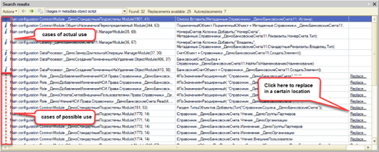
Fig. 23. Search result
The left column shows the case of using the configuration object presented in this row: "i" describes the case of actual use, and "!" describes the case of possible use.
The far-right column shows the Replace... hyperlink. When you click this link, the old name of the configuration object is replaced with a new name in a certain location. After replacing the hyperlink will disappear. If there is no hyperlink in this column, the replacement has already been performed by the application.
To speed up the replacement process, you can select multiple rows in the search results and select Replace... from the context menu.
On the Subsystems tab, you can specify subsystems where the object is used. You can include an object in subsystems regardless of the mutual subordination of the subsystems. You can include an object both in the parent and the subordinate subsystems at the same time. When you include an object in subsystems, it defines command interface fragments where commands of the object to edit will be displayed. For more information on the command interface, see Command interface.
On the Data tab, you can create attributes, resources, dimensions, tables, table attributes, and other subordinate objects (depending on the object type). Besides, the tab can contain other controls to customize properties specific to particular object types.
For a catalog, for example, you can define the name and code length, specify a code type and the main presentation for a catalog item.
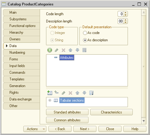
Fig. 24. "Data" tab
Use the tools panel buttons above the list of subordinate objects to add, remove, and arrange these objects. You can specify subordinate object properties in the property palette.
If the editing window is opened for an object that cannot be edited (for example, an object that is not stored in the repository), the type editing dialog box is opened in view-only mode.
On the Forms tab, you can manage object forms and select default forms.
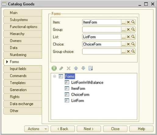
Fig. 25. "Forms" tab
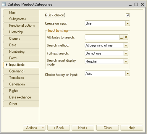
Fig. 26. Input field behavior
The Input by string group describes the object behavior upon the input by string. For more information on input by string, see Input by string.
The Quick choice property is responsible for the default selection mode. For more information on the property, see Quick choice.
On the Commands tab, you can specify custom commands related to the object. For the command type details, see Types of commands.
When you add a new form, the form wizard is started. You can use the wizard to select a form kind and attributes to place in the form and build the form. For details on how to use the form wizard, see Configuration object form wizard. For the main form editing techniques, see Form editor.
On the Templates tab, you can manage object templates.
When you add a new template, the template wizard is started. For details on how to use the template wizard, see Template wizard.
Below the template list, you can find the Wizards button. Click it to open a submenu to select a wizard type (available wizards depend on the object type):
-
If you select Print wizard, you will start the print wizard used to create a template and a procedure for printing. For details on how to use the print wizard, see Print wizard.
-
If you select Output form wizard, you will start the output (report) form wizard.
On the Rights tab, you can define rights on objects of this type for each created role.
On the Exchange plans tab, you can specify a list of objects of the ExchangePlan type for the following application objects: catalogs, documents, charts of characteristic types, charts of accounts, charts of calculation types, registers, business processes, and tasks. Select the checkboxes for exchange plans that record changes to the object to edit.
The Other tab contains buttons to open an object module, a manager module, and the help. The tab can also contain the Predefined button used to open the list of predefined object items (for catalogs, charts of characteristic types, charts of accounts, charts of calculation types). Besides, the tab can contain lock management attributes (see Managed locks) and full-text search settings (see Full-text search in data). These attributes are available only for the following application objects:
-
Catalogs
-
Documents
-
Charts of characteristic types
-
Charts of accounts
-
Charts of calculation types
-
Registers
-
Business processes
-
Tasks
Some objects can contain tabs specific to this object type:
-
Catalog object: Hierarchy, Owners, Numbering, and Generation.
-
Document object: Numbering, Register records, Journals, Sequences, and Generation.
-
ChartOfCharacteristicTypes object: Hierarchy.
-
ChartOfCalculationTypes object: Calculation and Generation.
-
ChartOfAccounts object: ExtDimension and Generation.
-
CalculationRegister object: Recalculation.
-
Task object: Addressing and Generation.
-
All registers: Recorders.
-
Object that can be recorded by exchange plans: Data exchange.
-
External data source: Functions.
-
External data source table: Generation.
2.13. Creating the help section
You can attach a text to some configuration objects to explain its purpose and usage. This text is called a user description. When operating with 1C:Enterprise system, the user can display the description on the screen to view.
To create and adjust a user description, use the built-in HTML editor. To call the editor, in the Help property of the object property palette, click Open. To create and edit a description text, use HTML editor tools. To set a name, in the chapter text, create a first-level header using the <H1> markup language tag. Note that the<style> tag (and its contents), which can be specified by manually editing the Help text outside the <BODY> tag, will be ignored when the Help chapter is displayed in 1C:Enterprise mode. If you want to apply a special design to the Help page, define it inside the <BODY> tag.
If the Include in help contents property is set, an item by the object synonym value can be included in the help content. Regardless of the property setting, a string by the object synonym value is included in the index list (to search in the help). Remember that the object appearance in the content tree depends on the value of the property with the same name in the subsystems that include the object (see Subsystems).
2.14. Operations with the database configuration
2.14.1. Database configuration object tree
You can open the database configuration window to view the structure of the database configuration, properties, forms, templates, and other information about objects. To do this, click Configuration – Database configuration – Open database configuration. It looks the same way as the Configuration window.
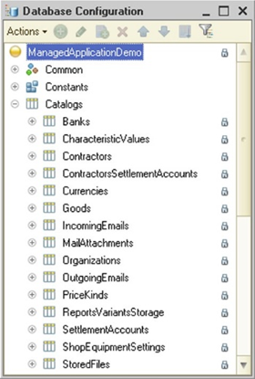
Fig. 27. Database configuration
Methods for operating with database configuration objects are similar to the methods for operating in the Configuration window. The only difference is that all database configuration objects are read-only (view-only).
2.14.2. Updating the database configuration
2.14.2.1. General information
When you edit a configuration, you can create new objects, modify existing ones, or delete them. The current database structure may differ from the configuration structure. The difference between configurations is shown in the Configuration window title by the characters <!>.
The <!> difference mark of configurations appears only after you save the changes in the main configuration. After you save the main configuration, you can continue making changes. In this case, the Configuration window title will show signs of change for both of the configurations.
To bring the configuration and the database configuration into compliance, update the database configuration. You can perform the update using the following methods:
-
Click Configuration – Update database configuration.
-
Click Configuration – Database configuration – Update database configuration on the server.
In the first case, before the restructuring is performed, you will be shown the dialog box (see Restructuring completion) with the changes to be made. In this dialog box, you can confirm or refuse the restructuring. In the second case (update on the server), no dialog box will be shown and the restructuring will be performed unconditionally.
If the main configuration has not been saved yet, Designer will save it and then update the database configuration. If a message window is opened when updating the database configuration, it is cleared.
Note. IMPORTANT. The database configuration update might require to stop all users' operations.
Before updating, you can compare configurations and merge them (see Comparing configurations and database configurations).
If debugging is performed at the time of database configuration update, the following question is displayed after saving the current configuration: To update the database configuration, stop debugging. Continue? When you answer Yes, debugging stops and the database configuration is updated. When you answer No, no update is performed, and debugging does not stop.
Updating the database configuration requires exclusive access of Designer to the infobase. Depending on whether users are operating with the database and their operation modes, there can be several options of the application behavior:
-
Designer generates an exclusive lock error if:
-
The database in the file mode is used.
-
There are sessions connected to the infobase without a web server.
-
There are no sessions running via a web server.
-
The configuration update requires to restructure the database.
-
-
Designer prompts you to close all sessions and retry the update if:
-
The configuration update requires to restructure the database.
-
Web clients or thin clients connected via a web server operate with the file infobase.
-
-
In other cases, Designer prompts you to perform a dynamic update.
Note. Note 1. Troubleshooting messages specify characteristics of the sessions that interfere with the action. If the number of sessions is less than or equal to 5, you are shown a detailed list of sessions with a computer name, an application type, and so on. Otherwise, the total number of sessions is displayed.
Note. Note 2. Running the infobase in exclusive mode does not switch the Microsoft SQL Server database to single-user mode.
Note. Note 3.To speed up the infobase restructuring when using the Microsoft SQL Server DBMS, it is recommended that you set recovery mode for the database toSimple or With incomplete logging. You can change the mode either temporarily before restructuring or permanently if you do not plan to restore the database for some time. Before changing the database restoring mode, back up the database.
2.14.2.2. Possible situations upon restructuring
2.14.2.2.1. Exclusive access error
If the application cannot obtain exclusive access, you can only wait until users are disconnected from the infobase and retry the update operation.
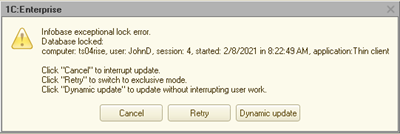
Fig. 28. Exclusive lock error
2.14.2.2.2. Closing sessions and trying to update
If the database configuration update requires to close all sessions, the user is shown a message (see fig. 29).
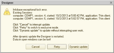
Fig. 29. Disabling sessions to update
If the Close sessions and repeat command is selected, the user is prompted to confirm the selected action and receives the following message: Closing sessions will result in abnormal termination of all infobase users' work. Do you want to close sessions?. If the answer is yes, an attempt to complete all the infobase sessions is made. Then the attempt to save the database configuration is repeated.
Closing all the sessions will result in abnormal termination of all client applications.
There can be situations when a session cannot be closed. For example, a file infobase is published on a web server that requires a client certificate or authentication using a username and a password. At the same time, connections to the infobase are made only via the web server. Designer does not support authenticated access to the web server and cannot attempt to close the sessions. If Designer fails to close the infobase sessions, you can try to update the database configuration later or close the sessions in other ways.
2.14.2.2.3. Dynamic update
If the dynamic update is available, a special message is shown to the user (see fig. 30).
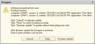
Fig. 30. Dynamic update
If you select Dynamic update, the update is performed without closing user sessions. The changes you make are written dynamically as a configuration change version. In this case, the database configuration is not changed. You can make repeated changes to the main configuration. If you can set the exclusive mode upon the next attempt to update the database configuration, Designer updates the database configuration considering all the current and previous changes.
If the dynamic update has been performed, users operating at that moment continue operating with the old configuration. To start operating with the updated configuration, the user needs to restart 1C:Enterprise application. To monitor and notify users of dynamic changes that have been made, use the DataBaseConfigurationChangedDynamically() global context method.
Note. Note. After the database configuration update is completed, all versions created by the dynamic update will be deleted.
2.14.2.3. Restructuring completion
If the application detects changes that require to restructure the database, you are shown a dialog box with these changes to confirm the update.
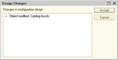
Fig. 31. Restructuring data
To confirm saving, click Accept. To cancel saving, click Cancel.
2.14.2.4. Restructuring mechanism selection
There are two ways of restructuring:
- Usual restructuring mechanism. The only restructuring option available in 1C:Enterprise 8.3.10 or earlier.
In this mode, restructuring is always performed in the following way: each table to change is copied and each data row is converted in Designer or on the server (depending on the restructuring settings).
- Optimized restructuring mechanism. It is available only in the client/server mode of the infobase if Microsoft SQL Server or PostgreSQL is used.
In this mode, the application tries to perform as many actions as possible at the DBMS. Also, it tries to modify the existing data and indexes instead of copying and transferring data with its processing. In this mode, most actions are performed on 1C:Enterprise server.
When restructuring from Designer, the used restructuring mechanism is defined by the UpdateDBCfg parameter in the conf.cfg file. The configuration file is analyzed on the computer where it is opened. The specified restructuring mechanism (simple or on the server) determines whether you are shown the dialog box where you can confirm or refuse the restructuring.
When restructuring using the command line in Designer batch run mode (the /UpdateDBCfg command), the used restructuring mechanism is determined directly in the command line. If the command line does not specify the used mechanism, the conf.cfg configuration file will be used for selection.
See also:
-
conf.cfg file.
-
/UpdateDBCfg command.
2.14.3. Background database configuration update
2.14.3.1. General description
Note. Note. Available only for CORP licenses.
The database configuration update that is related to the database restructuring and performed for large infobases might take a long time. During the update, you cannot operate with the infobase.
In order to minimize the loss of time on this operation, there is a special mode that updates the database configuration in the background. The background update of the database configuration has the following features:
-
It is available only in the client/server mode of the infobase.
-
It can be executed when Designer is closed.
-
The biggest part of the background database configuration update is performed without exclusive access to the database (including the database restructuring).
-
You cannot perform the following actions during a background update:
-
Edit the configuration.
-
Application debugging.
-
Execute a background database configuration update.
-
Do not use the following methods: SetAggregatesMode(), SetAggregatesUsing(), and RebuildAggregatesUsing().
-
Change contents of the chart of accounts or the chart of calculation types if the related accounting register or calculation register participates in the background update. An attempt to modify these charts of accounts or charts of calculation types leads to an error.
-
-
You can pause a background configuration update for up to 48 hours. If the "pause" lasts more than 48 hours, the background update will be canceled.
-
Background updates are not supported for configurations in compatibility mode with version 8.1 (see Specifying compatibility properties).
-
Background update of database configuration is not supported for DBMS IBM Db2 9.1.
The background configuration update process consists of several steps:
-
Processing phase:
-
It is running for a long time.
-
This phase can be started in any way:
-
Interactively or from Designer.
-
Using the Designer batch run mode.
-
-
During the phase, users can operate with the infobase.
-
The main part of data is restructured for the following configuration objects:
-
Catalogs
-
Documents
-
Document journals
-
Information registers
-
Accumulation registers
-
Accounting registers
-
Calculation registers
-
Sequences
-
Charts of accounts
-
Business processes
-
Tasks
-
-
During the processing phase, the application captures all changed data for the above objects, similar to the data exchange mechanisms.
-
-
Update phase:
-
It starts automatically after the end of the processing phase, at an interval of 1 minute.
-
During the phase, users can operate with the infobase.
-
The phase consists of automatically repeated iterations. Each iteration analyzes the changes that have been accumulated since the previous iteration (or the completion of the processing phase) and restructures the accumulated changes.
-
Iterations are completed at the time of transition to the next phase.
-
-
Change acceptance phase:
-
It requires exclusive access to the infobase.
-
During the phase, users cannot operate with the infobase.
-
The first step of this phase is to update the data accumulated since the last (i. e. before the current phase) iteration of the update phase.
-
Then the data that is not involved in the processing and update phases is restructured. This data is not expected to have a lot of changes, so it is restructured quickly.
-
The next step is to accept all the changes made to the database.
-
After that, the database configuration update is completed.
-
If the background update is running so that you do not need to restructure the database, then all updates are made in the change acceptance phase, which you can run immediately after the background update starts.
During the background update, you can stop the server or pause the background update process.
After the server is stopped or after the shutdown of the working process that supports the system background job executing the update, the first session will take a slightly longer time than usual. It happens due to restoring the background update. However, the background update process itself is in a suspended state. To continue, resume the background update. This behavior is implemented to ensure that no system looping occurs if the background update itself caused the shutdown of the working process servicing the background update.
After the server is restored, the background update of the database configuration continues as follows:
-
If the operation is interrupted during the processing phase, the process continues from the last configuration object that has not been processed.
-
If the operation is interrupted during the update phase, the incomplete iteration begins anew.
Note. Tip. It is recommended that you cancel the running background update of the database configuration when you do not plan to complete this background update. For example, the process is put on an infinite "pause". It will have a positive impact on the application performance since there will be no registration of changes for the update phase.
When performing the background restructuring operation, consider the following application behavior features:
-
If an accounting or accumulation register is added to the separator, this register is processed during the change acceptance phase.
-
If you change the independent separator type (seeData separation feature), all objects included in this separator are processed during the change acceptance phase.
-
If you change the type of the dimension included in the main filter of the independent information register, the register is processed during the change acceptance phase.
2.14.3.2. Dialog box of the background database configuration update
To call the operation of the background database configuration update, click Configuration – Database configuration – Background database configuration update.

Fig. 32. Dialog box of the background database configuration update
Click Start to start the processing phase. The service message window will display the following text:
Background database
configuration update started successfully. The configuration is
not available for editing. Background database configuration update is running.After the background update is started, the configuration is locked from any modifications. During any phase, you can pause the background update clicking Pause. To continue the background update, click Continue.
After the processing phase is completed, the update phase begins. During this phase, you can move the application to the change acceptance phase by clicking Finish or Cancel.
Note. Tip. It is recommended that you cancel the running background update of the database configuration when you do not plan to complete this background update. For example, the process is put on an infinite "pause". It will have a positive impact on the application performance since there will be no registration of changes for the update phase.
Select the Allow dynamic update checkbox to specify that the system must try to start a dynamic update when you click Start instead of running the background database configuration update. If this checkbox is selected, the option to perform a dynamic update of the configuration will be checked immediately after you click Start. If the configuration allows this option, a dynamic update will be performed instead of the background database configuration update.
Select the Execute on server checkbox to specify where to start, complete, and cancel the actions. If this checkbox is cleared, these actions are performed in the client application. If it is selected, the actions are performed on 1C:Enterprise server. Besides, if this checkbox is selected, you can perform a configuration update if you have only the UpdateDataBaseConfiguration update right, without the Administration right.
2.14.4. Saving database configurations to files
To save the database configuration to a file on the hard drive, click Configuration – Database configuration – Save database configuration to file. This will open the standard file selection dialog box. Select a directory and specify a name of the file to save the database configuration.
The saved database configuration file is required to compare and merge configurations (see Comparing and merging configurations).
2.14.5. Comparing configurations and database configurations
If you need to get a report on differences from the database configuration when making changes to the configuration, click Configuration – Database configuration – Compare and merge with database configuration.
If necessary, you can restore the modified objects.
2.14.6. Cancelling configuration changes
To undo the configuration changes, click Configuration – Database configuration – Return to database configuration.
Note. Note. TheSave database configuration to file... and Return to database configuration menu items are available even in the closed editable configuration. The Return to database configuration command is still unavailable when the infobase is connected to the configuration repository.
2.15. Starting 1C:Enterprise
You can start 1C:Enterprise from Designer. To do this, click Service – 1C:Enterprise. You might need to start 1C:Enterprise in debug mode. To do this, click Debug – Start debugging. For more information on the Debugger, see Debugger.
If the configuration has been modified (changed), Designer displays the following question: The configuration you are editing is different from the database configuration. Update the database configuration? Select Yes to save your changes. If you select No, 1C:Enterprise mode is started without saving the configuration.
If the application is launched from the infobase list and its configuration is not updated (a situation similar to the one described at the beginning of this section), the user will be prompted with the following question: The database configuration does not match the saved configuration. Continue? If you select Yes, 1C:Enterprise mode is started with the previous database configuration. If you select No, 1C:Enterprise mode is not started. To update the configuration, launch Designer and update the infobase configuration there (see Updating the database configuration).
2.16. Exporting and importing configuration files
The functionality of exporting and importing configuration files allows you to selectively import or export configuration object properties (modules, templates, and help). To export properties, click Configuration – Export configuration files.
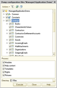
Fig. 33. Exporting configuration files
In the opened window, select configuration objects to export, specify a type of data to export and a directory to export to. To start unloading, click Run. Data to export is written to files with names matching the name of the property to export. The file extension matches the data type:
-
htm is used for HTML document help and templates.
-
txt is used for text document modules and templates.
-
mxl is used for spreadsheet document templates.
-
geo is used for geographical schema templates.
-
grs is used for graphical schema templates.
-
bin is used for binary data templates.
Pictures are exported in the format in which they are stored in the configuration. Pictures of all supported formats are imported (see Common pictures).
To export/import access rights, select the required roles (or all roles) and specify the Rights item in the Process list. Access rights are exported in XML format. The export file includes access rights, data access restrictions, and access restriction templates.
When you export the help and template files of HTML documents, a separate file is generated for each language for which a template is defined. The language code is included in the file name before its extension. For example, Document. GoodsConsumption.Help.ru.htm represents a file with the help information in Russian of the GoodsConsumption document.
To import data, click Configuration > Import configuration files. The actions in the window are similar to the actions described for the data export mode.
When importing, the application makes an attempt to import the help files and HTML document templates for each language defined in the application. If only one file is found upon importing (without specifying a language code in the name), it is imported for the current configuration language.
2.17. Dumping configurations to files/Restoring configurations from files
2.17.1. General information
This functionality allows you to export all configuration objects to XML files and import from them. All configuration objects are exported to one or several files. The main file in the dump is the Configuration.xml file, which describes configuration properties. Dumping can be performed in two formats: linear (see Linear export format) and hierarchical (see Hierarchical export format). You can perform partial dumping from files. To dump the configuration, click Configuration – Dump configuration to files. To restore the configuration, click Configuration – Restore configuration from files.
You can export and import a configuration extension (see Configuration extension). In this case, click Actions > Configuration (in the configuration extension window) or use the respective commands in the Configuration extensions dialog box (see In Designer mode). Extended or controlled properties will be exported.
If configuration objects contain references to missing configuration objects, the references are exported as an ID text presentation. When importing, they will also be restored as a reference to a missing configuration object (to preserve the identity of the two configurations). For managed form attributes and items, internal IDs used to save and restore settings are exported.
When you export roles, only values of rights that differ from default values at the time of export are exported. When defining default rights values, the Set rights for new objects and Set permissions for default attributes and tabular sections role properties are used. The values of these checkboxes are the default values for access rights to configuration objects and access rights to attributes and tabular sections, respectively.
Note. Note. Ordinary forms and interfaces of an ordinary application are exported in binary form.
If errors occur in files upon the export, a window with a list of errors is generated. If the errors are not critical, click Accept. To open the file that contains an error, select the error string.
2.17.2. Export format versions
Export files are versioned. The version number of the export format, depending on the version of the 1C:Enterprise application, is shown in the following table.
| Platform version | Format version |
|---|---|
| 8.3.6 | 1.0 |
| 8.3.7 | 2.0 |
| 8.3.8 | 2.1 |
| 8.3.9 | 2.2 up to version 8.3.9.1850 inclusive |
| 2.3 starting from version 8.3.9.2033 | |
| 8.3.10 | 2.4 |
| 8.3.11 | 2.5 |
| 8.3.12 | 2.6 |
| 8.3.13 | 2.7 |
| 8.3.14 | 2.8 |
| 8.3.15 | 2.9 |
| 8.3.16 | 2.9.1 |
| 8.3.17 | 2.10 |
| 8.3.18 | 2.11 |
| 8.3.19 | 2.12 |
| 8.3.20 | 2.13 |
| 8.3.21 | 2.14 |
| 8.3.22 | 2.15 |
| 8.3.23 | 2.16 |
| 8.3.24 | 2.17 |
| 8.3.25 | 2.18 |
| 8.3.26 | 2.19 |
| 8.3.27 | 2.20 |
Explicit specification of a version number in export files begins with version 2.0 (an export from the platform version 8.3.7 and later). If export files do not explicitly specify a version number, the export is considered to have version number 1.0.
The format version is the same for all configuration objects that can be exported to files. The format version is written to the root XML files of the configuration objects, as well as to the root XML files of some subordinate configuration objects. Export files with a format other than XML do not contain an indication of an export format version.
Files are always exported in a format of the current 1C:Enterprise platform version (a version from which they are exported).
Files are imported successfully only if their version is less than or equal to 1C:Enterprise platform version used to export the files.
2.17.3. Export formats
2.17.3.1. Hierarchical export format
When exporting in hierarchical format, all configuration objects are exported into a hierarchical file structure that is generated according to certain rules. All files and directories are generated within the directory specified in the export dialog box.
This directory will be called a root export directory. It is recommended that you do not specify a path to the root export directory if it is longer than 30 characters. In this case, the export is less likely to be aborted due to an error related to exceeding the path to the file to export.
All configuration objects are located in subdirectories that correspond to their types. For example, directories will be in the Catalogs subdirectory of the root export directory, documents will be in the Documents subdirectory, and so on. Configuration objects located in the General branch will also be exported to their subdirectories of the root export directory, without an intermediate subdirectory. The properties of the entire configuration are exported to the Configuration.xml file, which is placed directly in the root export directory.
Each object is exported as follows:
-
The object description is exported in an XML file with a name of the object. If the object has subordinate objects (attributes, commands, forms, and so on), a subdirectory with the object name is created in the same directory.
-
Subdirectories for all groups of subordinate objects, except attributes and tables, are generated in the object subdirectory. Attributes and tables are located in the XML file with the object description. The following subdirectories are displayed:
-
Forms. Forms subdirectory.
-
Commands. Commands subdirectory.
-
Templates. Templates subdirectory.
-
External data source cubes. Cubes subdirectory.
-
External data source tables. Tables subdirectory.
-
Other properties of the configuration object (including the configuration itself) are placed in Ext subdirectories of different levels of subordination.
-
-
If the subordinate object has a hierarchical structure, it is exported similar to the parent configuration object.
-
The Ext subdirectory can contain:
-
For the configuration itself:
-
Managed application module: ManagedApplicationModule.bsl.
-
Ordinary application module: OrdinaryApplicationModule.bsl.
-
External connection module: ExternalConnectionModule.bsl.
-
Session module: SessionModule.bsl.
-
-
For the configuration object:
-
Object module: ObjectModule.bsl.
-
Command module: CommandModule.bsl.
-
Object manager module: ManagerModule.bsl.
-
Record set module: RecordSetModule.bsl.
-
Value manager module: ValueManagerModule.bsl.
-
Predefined data: Predefined.xml.
-
Schedule of scheduled job: Schedule.xml.
-
Role rights: Rights.xml.
-
Template file: Template.xml.
-
Help information. In this case, a general description of the help is in the Help.xml file. Help files named <language code>.html are located in the Help directory. If help files contain absolute images, they are located in the _files subdirectory of the Help directory.
-
Graphical schema or business process diagram. In this case, a general description of the schema is located in the Flowchart.xml file. The Flowchart directory contains subdirectories with a description of the graphical schema items that are located in the Items subdirectory. Each item is represented as a subdirectory that contains an absolute picture.
-
-
For the subordinate configuration object:
-
Managed form module: Module.bsl.
-
Managed form description: Form.xml.
-
Absolute pictures of the managed form items.
-
Absolute pictures stored in common pictures (Common > Common pictures).
-
Help information. The help information for a subordinate object is stored similar to the help information for a configuration object.
-
-
-
The form is exported to the following structure:
-
The description of the form is exported to an XML file with its name.
-
It also creates a subdirectory with the name of the form that contains the Ext subdirectory.
-
The Ext subdirectory contains:
-
Managed form description: Form.xml.
-
The Form subdirectory.
-
The Form subdirectory contains a file with the form module: Module.bsl.
-
The Ext subdirectory contains the help information of the form to export (described above).
-
-
-
The template is exported to the following structure:
-
The template description is exported in an XML file with the template name.
-
It also creates a subdirectory with the name of the template that contains the Ext subdirectory.
-
The Ext subdirectory contains the following information:
-
Template.txt. Template placed as a text document.
-
Template.xml. Template placed as an HTML document with further structure of similar help information.
-
Template.bin. Templates in all other formats.
-
-
-
External data source cubes are exported to the following structure:
-
The external data source is exported to an XML file with the source name.
-
It also creates a subdirectory with the name of the external data source that contains the Cubes subdirectory.
-
Cubes are exported as follows:
-
Each cube is exported in an XML file with the name of the cube.
-
It also creates a subdirectory with the name of the cube that contains the DimensionTables subdirectory.
-
The DimensionTables subdirectory contains files describing dimension tables with their own names.
-
-
-
External data source tables are exported to the following structure:
-
The external data source is exported to an XML file with the source name.
-
It also creates a subdirectory with the name of the external data source that contains the Tables subdirectory.
-
Tables are exported as follows:
-
Each table is exported in an XML file with the name of the table.
-
A subdirectory with a table name is also created.
-
Each table is exported as a separate configuration object.
-
-
-
Subsystems are exported to the following structure:
-
A subsystem is exported as an ordinary configuration object.
-
If a subsystem has subordinate subsystems, the Subsystems subdirectory will be created in a directory with the subsystem name. Subordinate subsystems will be exported to this subdirectory.
-
It is not recommended to use more than three nested subsystems, including the top-level subsystem, in order not to break the restriction on the full path to files of subsystem objects (255 characters). If the application requires more than three nested subsystems, it is recommended that you use as short subsystem names as possible.
-
The following table contains a mapping between configuration objects and directories where these objects will be exported:
| Export subdirectory name | Object |
|---|---|
| AccumulationRegisters | Accumulation registers |
| BusinessProcesses | Business processes |
| Catalogs | Catalogs |
| ChartsOfAccounts | Charts of accounts |
| ChartsOfCalculationTypes | Charts of calculations |
| ChartsOfCharacteristicTypes | Charts of characteristic types |
| CommandGroups | Command groups |
| CommonCommands | Common commands |
| CommonForms | Common forms |
| CommonModules | Common modules |
| CommonPictures | Common pictures |
| CommonTemplates | Common templates |
| Constants | Constants |
| DataProcessors | Data processors |
| DefinedTypes | Type collections |
| DocumentJournals | Document journals |
| Documents | Documents |
| Enums | Enumerations |
| ExchangePlans | Exchange plans |
| Ext | Additional data |
| ExternalDataSources | External data sources |
| FilterCriteria | Filter criteria |
| FunctionalOptions | Functional options |
| FunctionalOptionsParameters | Functional option parameters |
| HTTPServices | HTTP services |
| InformationRegisters | Information registers |
| Languages | Languages |
| Reports | Reports |
| Roles | Roles |
| ScheduledJobs | Scheduled jobs |
| Sequences | Sequences |
| SessionParameters | Session parameters |
| SettingsStorages | Settings storages |
| StyleItems | Style items |
| Styles | Styles |
| Subsystems | Subsystems |
| Tasks | Tasks |
| WebServices | Web services |
| WSReferences | WS references |
| XDTOPackages | XDTO packages |
2.17.3.2. Linear export format
Note. Important. The linear export format is obsolete. We do not recommend to use this format. The standalone server does not support the linear export format. We recommend to use the hierarchical export format.
The following items are exported to separate files:
- Configuration objects. Top-level objects and subordinate objects that are separately captured in the configuration repository.
Examples of file names:
-
Document.GoodsSales.xml. The Document.GoodsSales configuration object description.
-
CommonPicture.SalesSubsystem.xml. The CommonPicture.SalesSubsystem configuration object description (but not the picture itself).
-
Separate properties. As a rule, these are properties that have a large volume or a complex structure.
Examples of file names:
-
CommonPicture.SalesSubsystem.Picture.xml. Picture description (but not the picture itself).
-
DataProcessor.Guide.Template.MainPage.xml. Description of the template located in the data processor (but not the template itself).
-
Separate properties values that are files of known formats (but not XML). These files include form modules, templates, pictures.
Examples of file names:
-
CommonPicture.SalesSubsystem.Picture.Picture.png. Picture saved to common pictures with the SalesSubsystem name.
-
Catalog.Goods.Form.ItemForm.Form.Module.txt. Managed form module of the Goods catalog item.
-
DataProcessor.AssistantForDataExchangeCreation.Form.Form.Form.SecondInfobasePicture.Picture.png. Absolute picture contained in the Picture property of the SecondInfobasePicture managed form item.
Objects that are not development objects are stored in the parent object file. For example, the DataProcessor.PrintLabelsAndPriceTags.Template.PrintBarcodesComponentLinux32.Template.bin file denotes an add-in to print labels and price tags located in the binary PrintBarcodesComponentLinux32 template.
The following items are exported in a special way:
- Object module. It is exported as a text file (if it can be obtained) or in a binary form.
An example of file name:
-
DataProcessor.EventLog.ObjectModule.txt. The DataProcessor.EventLog metadata object module.
-
HTML. It is exported as a file set: root property file, HTML page files, and image files (if any). A root file contains a list of HTML pages included in the document. HTML files are pages included in the document. Each page corresponds to a specific language defined in the configuration. Configuration object help is a special case of HTML export.
Examples of file names (for the Help property):
-
Catalog.Goods.Help.xml. Root file of the external help property of the Catalog.Goods metadata object.
-
Catalog.Goods.Help.ru.html, Catalog.Goods.Help.en.html. Help pages for the Russian and English languages respectively.
-
Catalog.Goods.Help.Picture.png Picture file that is included in the HTML document with the help.
-
Vendor configurations. They are exported as a vendor configuration information file in the internal format (not XML) and configuration files (.cf) for each vendor configuration.
Examples of file names:
-
Configuration.ParentConfigurations. Information file on vendor configurations.
-
Configuration.ParentConfigurations.TradeManagement.cf. The TradeManagement vendor configuration.
When exporting, all references to metadata objects, field references, type IDs, and so on are exported as names (Catalog.Goods). All IDs are exported in English. A reference to the Goods catalog will look like Catalog.Goods.
When using linear format, consider the following possible issues:
-
Migrating the export directory between different file systems might be difficult.
-
In some cases, issues occur with the uniqueness of file names of objects to export.
2.17.4. Dumping
A configuration can be dumped in two different formats: linear or hierarchical. Only the hierarchical format is available for dumping from Designer. Dumping in the linear format is an obsolete option. We do not recommend to use this format. You can dump a configuration in the linear format only using Designer batch run mode.
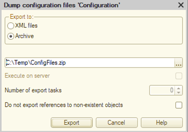
Fig. 34. Dumping configurations to files
In the dialog box, you can specify whether you want to dump a configuration as an XML file or a ZIP archive. A dumped ZIP archive takes less space. Sending ZIP archives via communication channels also takes less time. The archive structure matches the dump directory structure.
In the dialog box, you can also specify that dumping must be performed on the server (in client/server mode). To do it, select the Execute on server checkbox. In this case, dumping will be performed simultaneously by several system background jobs. If you select dumping on the server, you can specify the number of system background jobs to use for dumping. If the Number of dumping jobs parameter is set to zero, the platform will automatically define the number based on the processor parameters of the computer with 1C:Enterprise server cluster.
After you specify a dump directory and a dumping method, the actual dumping is performed. When dumping (as mentioned earlier), a Configuration.xml file is generated. It contains configuration properties. However, in addition to this file, the application generates a version file (ConfigDumpInfo.xml) that contains information about an object name and version. If you later attempt to dump the current configuration to files to this directory, Designer will export only those objects whose version is different from the version used during the previous dump. In this case, the "version" refers to a sequence of characters that will be different from the previous version (a sequence of characters) if the object has been edited. This is the only purpose of this information.
If the dump directory does not contain a version file, the configuration will be fully dumped (with the generation of this file). The full dump will be performed if any of the following changes are detected during the dump update:
-
The configuration is renamed.
-
A configuration object is renamed or deleted.
-
The PredefinedData or BusinessPocessDiagram properties are changed. The configuration can have references to predefined data items and business process points, so changes in these properties affect the configuration dump integrity.
Remember that the export format in a directory selected for export must match the current export format. In other words, if you export in the hierarchical format and try to dump a configuration in the linear format to the same directory, you will receive an error and the configuration will not be dumped.
See also:
-
Export formats (see Export formats).
-
ConfigDumpInfo.xml.
2.17.5. Loading
2.17.5.1. General information
To load the configuration, click Main menu – Configuration – Load configuration from files in Designer. In the dialog box, specify the directory that contains files of the configuration to load.
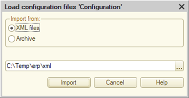
Fig. 35. Loading configuration from files
If the Load from: Archive mode is selected in the dialog box, specify the ZIP archive that contains files of the configuration to load in the Directory dialog box field.
The loading can be divided into two types, significantly different in operating time:
-
Full load
-
Partial load
When you perform any load, remember that the application does not check support settings when loading from XML. Accordingly, when performing this operation, the user is responsible for ensuring that the support settings are correct. Note that loading incorrect support settings might damage the configuration update feature to fail and the configuration itself.
2.17.5.2. Full load
Full load replaces the main configuration with data located in files to load. Full load of a sufficiently large configuration can take a significant time.
When you perform a full load of a configuration from files, the following features are available:
-
A configuration that does not support and is not connected to the configuration repository can be loaded without restrictions.
-
A configuration that is connected to the configuration repository cannot be loaded (the corresponding menu item is not available).
-
A supported configuration can only be loaded if the following conditions are met:
-
Changes are enabled.
-
All configuration objects are editable.
-
2.17.5.3. Partial load
2.17.5.3.1. General information
Full configuration load from XML files takes a significant time. However, the changes do not always affect most configuration files. Often, only some configuration objects require loading. To speed up loading in such cases, there is a partial load of configuration from XML files.
Partial load can be performed for both a configuration object and subordinate objects (forms, help, modules, and so on). If an object is loaded, it is loaded completely along with all the subordinate objects. Objects from files with configuration objects are mapped by their full name and an internal ID. For subordinate objects, the parent object is defined by the file name (linear format) or directory hierarchy (hierarchical format).
Partial load can only be performed using the /LoadConfFromFiles key of Designer batch run mode and is not supported interactively. Also, partial load is not supported when operating with multiple extensions.
The general procedure for partial load is as follows:
-
Prepare files to load in the configuration. File format and location fully correspond to dumped files in the selected format: linear (see Linear export format) or hierarchical (see Hierarchical export format).
-
Run Designer in batch run mode and specify a list of changed files and the format of the files to load.
-
If no error occurs upon loading, the configuration is saved. If errors occur upon loading, the system returns to the last saved main configuration. If there are changes and unsaved data in the configuration you attempt to load, they will be lost.
During partial load, you can use the /Out command-line switch to get a file with diagnostic messages that are generated during the partial load.
When you perform the partial load of a configuration from files, the following features are available:
-
You can load only if all objects to load are captured in the configuration repository.
-
You can load if all objects to load are enabled for modification (for a supported configuration).
-
When you perform the partial load of a root configuration item, the configuration is no longer supported if a file of the external ParentConfigurations.bin property (stores information on the support settings) is absent.
Below, you can read about different situations of partial load.
2.17.5.3.2. Adding objects
To add an object, import the required object and its parent. When you try to import a new object, an error may occur:
-
If a name of the object to import is not unique.
-
If the object has a reference to a subordinate object but no files are provided for the subordinate object.
If there are no files for subordinate objects and no references to them, these objects will take default values.
2.17.5.3.3. Deleting objects
To delete an object, import a parent object file that does not contain information about the object to delete.
2.17.5.3.4. Renaming objects
To rename an object, import the object with all subordinate objects and an object parent with all subordinate objects. The parent must contain references to the object with a new name. When files with subordinate objects are missing upon import, these objects take default values if there are no references to them. If there are references, an import error is thrown.
2.17.5.3.5. Changing objects
If you need to change an object in any way, load the information about the modified object and all its subordinate objects. When files with subordinate objects are missing upon import, these objects take default values if there are no references to them. If there are references, an import error is thrown.
2.17.5.3.6. Importing subordinate objects
When importing subordinate objects, objects to import must be described by files the same way they are described upon export. For linear dumping, this means that file names must match the names upon export. For hierarchical dumping, file names must match, and the directory hierarchy must be the same.
For example, if you want to import help information for the Goods directory, specify the following import command:
1cv8 DESIGNER /IBName "IBName" /LoadConfigFromFiles D:\Source -files D:\Source\Catalogs\Goods\Ext\Help.xmlYou need to create the following directory structure on the hard drive D: (in case of hierarchical dumping):
\Source
\Catalogs
\Goods
\Ext
Help.xml
\Help
ru.html
en.htmlUpon import, specify only a name of the object to import (in this case, it is help information: Help.xml). Subordinate objects (help files in respective languages) must be located on the hard drive, and they will be used automatically.
The command to import a module of the Counterparties catalog object will look similar. Import command:
1cv8 DESIGNER /IBName "IBName" /LoadConfigFromFiles D:\Source -files D:\Source\Catalogs\Counterparties\Ext\ObjectModule.bslYou need to create the following directory structure on the hard drive D: (in case of hierarchical dumping):
\Source
\Catalogs
\Counterparties
\Ext
ObjectModule.bsl2.18. Configuration extensions
To open a list of connected configuration extensions, in the main menu, click Configuration – Configuration extensions. In the window that opens, you can create new extensions and manage connected ones. For more information on how to use the window for extension operations, see In Designer mode.
2.19. Operations with the mobile client
For more information on mobile client operations, see Development for mobile devices.
2.20. Configuration report
Designer can display information about all configuration objects in a text or tabular form. To do this, select Configuration – Configuration report.
This opens the following dialog box. Select a type (text or tabular) and a name of the file where you want to save the configuration structure description.
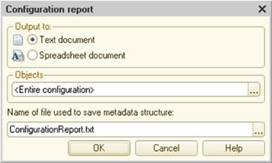
Fig. 36. Configuration report
Creating a description of configuration objects for complex configurations can take a long time.
If you want to get a report on individual configuration objects, in the Objects field, click the selection button and select checkboxes for the desired objects in the object selection dialog box.
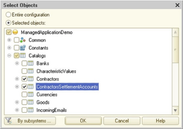
Fig. 37. Selecting objects for the configuration report
Subsystem filter is available.
After the configuration description is completed, a window will open with the description in the selected format (text or tabular).
2.21. Global search and replacement
The global search and replacement mode is designed to find a specific string in all modules, dialog boxes, spreadsheet documents, configuration descriptions, and external files (external reports and processing, spreadsheet documents). The found text can be replaced by another one. This mode can be used, for example, to find all calls to a certain global procedure or to refer to any details in different modules.
To call search mode, click Edit > Global search. To call replacement mode, click Edit > Global replacement.
These modes use the same dialog box. If the search mode is selected, the replacement mode details become unavailable. Therefore, for brevity, we consider the procedure of global replacement, and then specify the features of the search mode.
This opens the replacement dialog box.
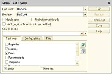
Fig. 38. Global replacement window
In the Search field of this dialog box, enter a search pattern or select a pattern from those that were previously used in the search operations from the history list.
In the Replace field, enter a text that you want to replace the found text with or select a pattern from those that were previously used in the replace operations from the history list.
To make the search case-sensitive, select the Match case checkbox. To find only whole words, select the Find whole words only checkbox.
If you do not want to open editors during the global replacement (the Replace all button), select the Silent global replace (do not open editors) checkbox. In any state of the checkbox, the editor will open when you click Search or Replace.
Below, you can find a panel whose tabs indicate where to search for the specified pattern.
On the Text types tab, mark types of objects that will be searched. If you are editing the configuration for Managed application startup mode (see Overall), user interfaces will be excluded from the list of objects.
On the Configurations tab, you can specify configuration sections to be searched with precision to an object.
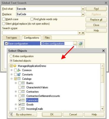
Fig. 39. Global search
The configuration list includes the main configuration, the database configuration, repository configurations, extension configurations (if they are opened), and configurations of extensions stored in the database (for opened extensions). Repository configurations must be opened before the search or replace mode is called. Database configurations (main and extension) are available only when using the global search.
To specify a set of objects, select the Selected objects radio button and mark objects to be searched. The first time you start the list, all objects are marked by default. To remove the marks, clear the checkbox on the configuration name line. You can then specify specific objects to search.
On the Files tab, you can specify a directory and file types to perform the search. Files of the following types can be viewed: configurations located in files (saved files, distribution files), external reports and data processors, text and spreadsheet documents. If a directory is not specified (the Directory attribute is not filled), the search in files is not performed. The search can also be done in open documents of the same types. To do this, select the Search in open documents checkbox.
You can save the selected settings composition for further use. To do this, specify the name of the setting in the Search area field. To switch to a previously saved setting, select its name in the drop-down list. The following settings are saved: settings on the Text types tab, objects only for the main configuration on the Configurations tab, and settings on the Files tab.
If you started the search mode, you need to click the Search button to start the search.
In global search mode, you can interrupt the process by pressing Ctrl + Break or Ctrl + Alt + E.
The Search results window displays a list of found occurrences of the source text.
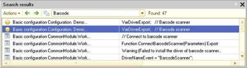
Fig. 40. Global search result
If any module has access restriction (see Configuration modules access restriction), the application prompts for the access password before searching for source text in this module. Enter the correct password or refuse to enter a password. If the password is not entered, then viewing in this module is not performed.
You can view the search result, and you can navigate to each value found if you select the required line and press Enter. To view the next or previous found value, you can click Actions – Next item and Actions – Previous item.
To copy the search result (the entire list) to the clipboard, click Copy on the window context menu or use the respective tools panel button on the search result window. Also, you can output the search result to a spreadsheet or text document.
To change the column width, use the mouse pointer while pressing Ctrl.
If you have started the replacement mode, the With text field shows a sample text used to replace the source text specified in the Replace field.
If you want to see the source text before you replace it, click Search to start the search. The result of the first found source is displayed. If you click Search again, the current text is skipped and the next occurrence of the source text in the current window or another window containing the source text is displayed.
To perform the global replacement (without confirmation of each replacement), click Replace all. If you do not want to open the objects where the source code occurrence is found, select the Silent global replace (do not open editors) checkbox.
Note. IMPORTANT. You cannot change the search criteria while viewing the search results.
The selection structure of the search scope (text types, list of configuration objects, files, and open documents) is remembered and restored when you open dialog box next time. If you want to save multiple scopes, name each area in the Search area attribute. If you reopen the search window in the list of scopes, select the desired one and perform a search.
2.22. Customizing Designer work area
To create and edit a configuration, you need to use multiple windows at the same time. For example, you view, select, add, and delete configuration objects in the Configuration window, edit properties of objects and their components in the property palette, receive background information on 1C:Enterprise language in the syntax-assistant window, messages and search results are displayed in the message window. Besides, each configuration object can generally consist of different parts and each part is edited in a separate window.
Simultaneous opening of various service windows noticeably narrows the work area intended for editing applied objects (forms, modules, and templates) and common configuration objects (application module and common modules, templates, styles, interfaces, and so on).
To extend the work area and usability, you can use some guidelines for customizing different Designer panels, the presence and behavior of various service windows, and the use of window display modes.
2.22.1. Panel customization
Designer is designed to maximize the work area by automatically selecting the desired tools panels for each window view. For example, when you edit a spreadsheet document, Designer provides you with a tools panel for editing this document. When you navigate to the window that contains a form module, Designer closes the spreadsheet document tools panel and displays the text editor tools panel.
The user can customize tools panel components and their placement on the screen. If you are configuring a standard command panel to place commands that are not present in this panel by default, it is possible that after the Designer is restarted, the command bar order will be changed. In this case, hide the standard panel and create an additional command bar placing the required commands in the correct order. The order of commands on it will not change.
Besides tools panels, Window bar and Status bar are located below. Each of them occupies a separate line and cannot be moved to another location. If any panel is not needed, you can hide it using the context menu anywhere in any panel. The panel is displayed if the checkbox is selected to the left of its name and is hidden if the checkbox is cleared. To change the display mode of the panel, select the line with the panel name in the context menu.
If you do not want the window bar to occupy a part of the application work area, you can enable the Autohide mode. When you operate, the window panel is hidden. To show it, hover over the window bar location.
2.22.2. "Configuration" window
You can open and close the Configuration window at any time. After selecting all the required windows for operation, the Configuration window can be closed. Closing the window does not close the configuration. You can open it at any time.
The initial state of the window is Configuration – Docked. In this state, it "overlaps" all windows that are in the Ordinary state (most windows are shown in this state). To use the area occupied by the Configuration window, you can change its state to Ordinary (in this case, other windows will appear on top of the Configuration window) or Autohide (if the window is not needed, it hides automatically; when you hover over it, the mouse pointer expands).
2.22.3. Using window display modes
In the Ordinary window mode, the window can be visible only within the free work area of Designer. Other modes allow you to extend the work area or use it more efficiently. You can also “move” the window out of the work area.
Each window (except the calculator) in Designer can be put into Autohide mode. This mode allows you to select the desired window for viewing and editing by hovering over the window title line. When the view is finished, simply move the mouse pointer to any other window or the title of another hiding window to minimize the window. In this mode, it is advisable to use the windows that are of a short-term nature (the Syntax Assistant, the Configuration window, the message and search results window, as well as the applied objects window, spreadsheet and text documents opened mainly for viewing).
The Float window state mode allows you to place this window anywhere on the screen, regardless of the Designer window size and position.
In the Docked mode, you can dock a window to another window in this state or to one of the sides of the window. Also, you can locate the window on top of another docked window (stacked windows).
Stack windows that do not need to be viewed at the same time. For example, the property palette window and the Syntax Assistant window or Immediate window and Call stack upon debugging.
For more information on window display modes, see Switching between application windows.
2.23. Saving the configuration ID to a file
It is an internal command used for the licensing validation mechanism.
2.24. Operating with configurations using 1C:Enterprise language
With 1C:Enterprise language, you can analyze the configuration metadata that is currently being executed. Use the Metadata global context property for this purpose. This property allows you to access an object of the ConfigurationMetadataObject type. The object properties provide you with information about the configuration properties, the number and composition of configuration objects.
In addition to the main configuration analysis, the application allows you to analyze any other configuration or extension of the configuration stored in the file. To perform this analysis, create the ConfigurationMetadataObject object based on the configuration file or the configuration extension file.
Configuration = New ConfigurationMetadataObject(New BinaryData(PathToConfiguration));As a result, the Configuration variable will have an object similar to the Metadata global context property. The value of the Configuration variable will describe a configuration located in the file system by the path specified in the PathToConfiguration variable.
You can also perform the following action:
Extension = New ConfigurationMetadataObject(ConfigurationExtensions.Get()[0].GetData());This example creates an object with metadata of the extension that was first added to the current configuration. If there are no extensions in the configuration, this sample code will cause a runtime error.
To get minimum information from a configuration or an extension (a configuration name, a configuration version, and a provider name), use the ConfigurationDescription object. To do it:
FromConfiguration = New ConfigurationDescription(New BinaryData(PathToConfiguration));This creates the ConfigurationDescription object based on the configuration. The path to the object is specified in the PathToConfiguration variable.
In addition to configuration structure and its basic characteristics, the application allows you to get some basic information from the configuration update file. This includes a description of the configuration resulting from the update and an array of configuration versions that can be updated using the specified .cfu file.
FromUpdate = New ConfigurationUpdateDescription(New BinaryData(PathToUpdate));As a result, the ConfigurationUpdateDescription type object will be placed in the FromUpdate variable.
See also:
- Updating configuration (see Configuration distribution and support).
Chapter 3. Application interface
3.1. Taxi interface
3.1.1. General information
In this mode, forms are opened in the main window work area. Some forms are still opened in separate windows, for example, selection windows. However, these windows do not appear on the taskbar. You cannot switch between windows using Alt + Tab. You can switch between open forms using special buttons in the header of all forms that are opened in the work area of the main application window.
3.1.2. Main application window
3.1.2.1. Main application window structure
Normally, a 1C:Enterprise application has a single main application window. The main window structure is optimized so that the user can easily navigate through the application and quickly find required sections and commands. The main application window does not open forms except the work area.
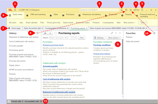
Fig. 41. Main window in the Taxi interface
In fig. 41, the following items of the main window are numbered:
-
Current section functions menu (and current section functions panel)
-
Global search field
-
Access to the notification center
-
Conversations, video calls, screen sharing (the menu is available only if the infobase is connected to the collaboration system)
-
Current user
-
Service and settings menu.
-
Sections panel
-
Open items panel
-
History
-
Main window work area
-
User work favorites
-
Server calls display panel
There are two options to display the main application window and other independent windows, such as calculator, calendar, or warning windows:
-
Without the operating system window title (fig. 41). Windows will be displayed this way when running on Windows including in remote desktop mode (RDP) and the RemoteApp remote application mode (for Windows 7 and later). In this case, the main panel is the window title.
-
With the operating system title. This option is used on Linux and macOS. In this case, the main panel is located under the OS title.
The main application window display options are switched automatically depending on the OS and environment where the client application is started. When the client application runs on Windows, you can manage the OS title display. To do it, use the GetOSCaptionRepresentation()/SetOSCaptionRepresentation() methods of the ClientApplication object. You can set the OS window title display only in the BeforeStart event handler.
Main panel contains the main methods for navigation through the application. The main panel contains the following items: button that opens the functions menu, application title, global search field, buttons that open the notification center, history, and favorites, current username, and button that opens the Service and settings menu.
Click Service and settings – Show M, M + , M– to manage buttons of the same name on the main panel. These buttons are displayed to the left of the global search field.
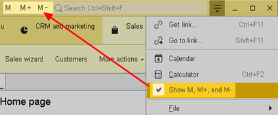
Fig. 42. Enabling memory operation buttons
When operating in the Taxi interface, several different panels can be located in the main application window (see Panel customization). The work area of the main application window displays all forms which the user is using. An exception is locking forms that are opened in separate windows. If you open a locking form (for example, a choice form) in a form opened in the work area, this form is displayed as a separate window and is not included in the window list on the taskbar. Depending on the window opening mode (see Forms), operations with either the owner form or the entire system interface are locked. If the auxiliary window is opened in the owner window lock mode, you still can open other forms and use the application command interface. If you switch to the form from which the form locking interaction with the owner is opened, the locking form is displayed.
Let us consider the components of the main application window in more detail.
3.1.2.2. Home page
To start using the application, open its home page.
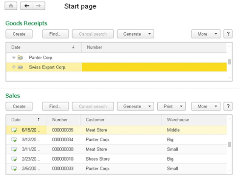
Fig. 43. Home page
This page is used by the application developer to display forms which are most commonly used in this application (as envisioned by the developer). Form availability on this page is determined by access rights and functional options. You cannot close the home page.
You can customize the home page interface using configuration properties (see Specifying presentation properties). You can also select home page forms from the list of available forms, which the application developer allows locating on the home page. To do this, use a special dialog box with home page settings: click Service and settings – Settings – Home page settings.
3.1.2.3. Sections panel
The section panel shows a list of top-level subsystems and allows you to quickly select the desired set of functions. Each section represents an application subsystem (for example, Sales, Purchases, or Inventory). For better visualization, you can set a meaningful picture for each subsystem. If a picture is not set, the subsystem is still displayed in the sections panel. The first section is always Quick menu. This section contains the most necessary and frequently used application tools. The other sections represent top-level subsystems.
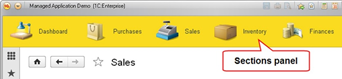
Fig. 44. Sections panel
The sections panel item groups system commands that are logically related to an activity within the application. For example, an activity related to purchase management (thePurchases section), inventory management (the Inventory section), and so on. The sections panel is not a tool to switch automated workspaces.
The sections panel can be scrolled. The sections panel content for a specific user is determined by their access rights and installed functional options. The user can control the visibility of available sections by clicking Service and settings – Settings – Sections panel setup.
When you click a section, the result depends on whether the current section functions panel is displayed (see Current section functions panel):
- The panel is not displayed. When you select a section, the section functions menu is displayed. In this case, the current section is not displayed (when the functions menu is closed).
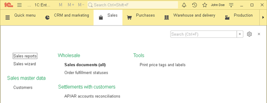
Fig. 45. Functions menu when selecting a section
- The panel is displayed. When you select a section, the functions menu is not opened but the current section command bar is changed. If the displayed information is insufficient, you can open the functions menu by re-selecting the section. In this case, the current section is always displayed on the sections panel.
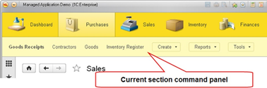
Fig. 46. Current section functions panel
The functions menu contains navigation panel and actions panel commands. You can add any command from the functions menu to your favorites. To do this, click the star icon to the left of the command name. To remove a command from the favorites, click the star icon again.
The upper right corner of the functions menu contains the search input field and the settings menu. The menu contains commands to set up the navigation panel (the Navigation settings command) and the actions panel (the Action settings command).
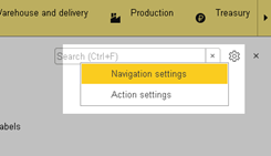
Fig. 47. Functions menu operations
To start the search, press Ctrl + F or start typing. After you enter your text, the left side of the functions menu panel shows Search in functions and an animation is displayed (during the search). The search is performed for commands of all sections, not just for the current section commands. The search result is displayed as follows:
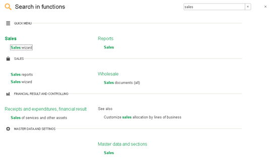
Fig. 48. Function search result
The search result includes commands whose presentation contains any of the words from the search string in any position. Found occurrences are highlighted. Commands of the Important category are not marked in bold. The found commands are grouped into sections (displaying the section image) and are placed in the same functions menu columns as when the search was disabled. The search is performed not only by the command presentations, but also by the command group presentations (except the See also group). If one or several words are found in the name of the group (section), then the search in the command presentations is performed without taking the word(s) into account.
To exit the search mode, you can clear the search field, click the clear search field button or press Esc.
There are several ways to open the functions menu:
-
Select a section.
-
Use the main panel command (see Main application window structure).
-
Use the keyboard:
-
Press F10.
-
Press Ctrl + Shift + T.
-
Press Alt + 2. In this case, the cursor is placed on the first command on the navigation panel.
-
Press Alt + 3. In this case, the cursor is placed on the first command on the actions panel.
-
Note. Note. If there are no sections in the sections panel (they are unavailable or hidden by the user), then the sections panel is automatically hidden.
3.1.2.4. Current section functions panel
The current section functions panel contains commands from the current section.

Fig. 49. Current section functions panel
Current section functions panel:
- Navigation panel commands are located at the beginning of the panel. The Important group commands are highlighted in bold.
If the panel is displayed horizontally, the maximum allowed number of commands (at least one) is displayed. If all the commands do not fit into the panel, the More submenu containing the remaining commands is displayed.
If the panel is displayed vertically, at least one and no more than 10 commands of the navigation panel are displayed. If the panel contains the More submenu, it is located as the 11th item of the command bar.
- Navigation panel commands are followed by submenus for all non-empty command groups of the navigation panel and the actions panel of the selected section.
3.1.2.5. Open items panel
This panel contains the list of forms opened in the current application session.
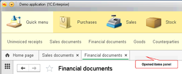
Fig. 50. Open items panel
The first open form is always the home page (if it is configured in the application). Forms of the home page work area are not displayed as separate forms on the open items panel. Clicking on the “cross” icon in the upper right corner of the panel element closes the form corresponding to this element.
If a form is locked by a form opened with the Lock parent window flag (the Window opening mode form property), then you cannot close the locked form using the "cross" icon on the open items panel.
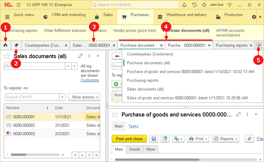
Fig. 51. Open items panel. Horizontal arrangement
In fig. 51, the following items are numbered:
-
Home page
-
Docked window
-
Form with a number in the header
-
Forms displayed side-by-side
-
"All windows" menu (open button and content)
The open items panel display depends on the panel orientation:
When the panel has a horizontal orientation:
-
A text in the panel items is displayed in one line.
-
A docked window is displayed as an icon without a text.
-
As the number of items increases, existing items begin to shrink reducing the amount of the displayed text.
-
If the open items panel contains items with a clipped text, then:
-
On the right side of the panel, a button to open the list of all windows is displayed.
-
An item for the home page is displayed as an icon without a text.
-
-
Two side-by-side windows are shown side by side as a single item.
-
The panel items, except for the home page and the docked window, display the closing ("cross") icon.
-
The header of a document or a business process form might contain a presentation of the document (business process) number. If the respective item of the open items panel cannot display the number from the presentation partially or entirely, the number is displayed in the right part of the panel item. The system tries to display the whole number.
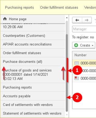
Fig. 52. Open items panel. Vertical orientation
In fig. 52, the following items are numbered:
-
Forms displayed side-by-side. Note that the separator between such forms is displayed in a special way. Arrows point at these specific features.
-
A scroll bar of the open items panel is displayed if the list of open windows does not fit into one screen.
When the panel has a vertical orientation:
-
A text in the panel items is displayed without limit on the number of lines.
-
If necessary, vertical scrolling is used and the home page is not included in scrollable items.
-
An item for the home page is displayed as an icon with a text.
-
Two side-by-side windows are shown one below the other as a single item.
-
The closing ("cross") icon is displayed on the panel items when you hover the mouse cursor over them (except the home page).
If you configure to display the open items panel in the main application window, then the home page button is hidden in the work area of the home page.
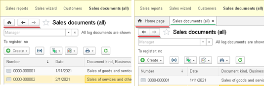
Fig. 53. Home page button
On the open items panel, you can change the order of items by dragging them. Also, you can close forms by clicking an open items panel item with the mouse wheel.
3.1.2.6. History
1C:Enterprise stores your operation history. You can use the history for quick access to infobase objects that you recently created or updated (such as documents or catalog items). The history contains URLs to application items ordered by the usage time. The history can be displayed as a history form or as a history panel.
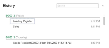
Fig. 54. History form
List items are grouped by a date when an application form was used. Within a date, items are ordered by the usage time that is displayed to the right of the item presentation.
The user history is stored in the infobase. If a single infobase object is opened multiple times on different days, each day contains a link to that object. If an object is opened several times within the same day, only the latest object opening is displayed in the history for that day. No more than 400 records can be stored per user. If the number of records exceeds 400, a new record replaces the oldest one.
If the history list is large enough, you can use a search function for convenience. You can enter a search query in the special field at the top of the form. To open it, press Ctrl + F or start typing the required text.
If the history is displayed in the main window panel (see Main application window structure), the list has the following specific features:
-
No grouping by dates and the application object usage time is not displayed.
-
When the panel orientation is horizontal, it displays the number of items fitting into the provided space.
-
When the panel orientation is vertical, it displays only the first 10 items.
-
When you click the panel title (History), the history form is opened.
To open the history form, use the tools panel command or press Ctrl + Shift + H.
Information is added to the user history in several ways:
- When manual operations (open, create, save) are performed.
When a user notification with a system object URL is displayed, the URL object is added to the history.
- When the user history is programmatically updated using the UserWorkHistory global context property.
If an object is saved or opened programmatically, the object information is not added to the history.
3.1.2.7. Favorites
The favorites contain a list of URLs to various application items that the user has marked for frequent use. The favorites can be displayed as a favorites form or as a favorites panel.
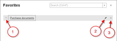
Fig. 55. Favorites form
In fig. 55, the following items are numbered:
-
Important favorites item flag
-
Button to edit the favorites item presentation
-
Button to delete a favorites item
Among your favorite items, you can select items that you use most often. To do this, click the button icon to the left of the item. This item will be highlighted in bold. Next time you open your favorites, it will be located at the top of the panel and will not change its position. You can also rename an item or remove it from the list.
If the favorites list is large enough, you can use the search function to find the required item. You can enter a search query in the special field at the top of the form. To open it, press Ctrl + F or start typing the required text.
If the history is displayed in the main window panel (see Main application window structure), the list has the following specific features:
-
You cannot search, rename, delete, or mark an important favorites item.
-
When the panel orientation is horizontal, it displays the number of items fitting into the provided space.
-
When the panel orientation is vertical, it displays only the first 10 items.
-
When you click the panel title (Favorites), the favorites form is opened.
To open the favorites form, use the tools panel command or press Ctrl + Shift + B.
The favorites are unavailable if the user does not have the SaveUserData access right (see Access rights description).
3.1.2.8. Conversations, video calls, screen sharing
If the infobase is connected to the collaboration system, you can use its features from a special menu that becomes available in the main window title of the application.
Fig. 56. Collaboration system menu
This menu includes the following:
-
Conversations opens the list of existing conversations.
-
New conversation. Create a new noncontext conversation.
-
Video call. Start a new video call or a video conference. Available only if video calls are enabled on current Collaboration System server.
-
Message history opens the message search form in the collaboration system. The form displays collaboration system messages for the selected date from noncontext conversations in which the current user participates. It also displays the messages from context conversations in which the current user received new message notifications.
Messages are grouped by conversations and sorted in ascending order of creation time. For messages, you can use the commands available in conversations. To generate a command list, call the handler attached by the AttachGenerateCommandsHandler() method.
In the history dialog box, you can change the date for which the messages are displayed, filter messages by author and message fragments.
- Settings opens the dialog box of collaboration system settings.
During screen sharing or a video call, the menu picture is changed. Besides, new commands appear on the menu.
Fig. 57. Collaboration system menu during a video call
Commands from the video call window are added to this menu.
See also:
- Collaboration system (see Collaboration system).
3.1.2.9. Notification center
The notification center provides access to unprocessed user notifications with the Important status.

Fig. 58. Notification center
If the user has unprocessed notifications, a notification center icon is displayed as it is shown in fig. 58.
When you click the notification center icon, a notification list is opened.
Fig. 59. List of notifications
When you click a notification or a notification window, the related action is performed (if it is set) and the notification is removed from the list. You can also delete all notifications at once using the Clear notifications command. In this case, actions set for the notifications are not performed.
If a collaboration system message is deleted from the notification center, the respective conversation is marked as read. The conversation is marked as read irrespective of the way the message is deleted: by clicking the Clear notifications hyperlink or the cross button of a specific message.
If the infobase is connected to the collaboration system, you can go from the notification list to the conversation list. To do this, click Conversations in the notification list. If the infobase is not connected to the collaboration system, the Conversations command will be hidden from the notification list.
3.1.2.10. Global search field
Global search field is a generic interface to the following functions: information search, calculator, tools to follow links (URLs and "usual" ones). You can modify the interface functionality using 1C:Enterprise language. The global search field is unavailable if a mode other than the ordinary one is set for the main application window (the Ordinary value in the Main client application window mode configuration properties).
The search is performed in the following sections by default:
-
Favorites
-
History
-
Functions menu
-
Messages from noncontext conversations (including one-on-one conversations) and noncontext conversation titles of the collaboration system
-
Infobase data (full-text search)
-
Application and platform help
To access the global search field, press Ctrl + Shift + F.
Fig. 60. Default state
The search results are shown in a drop-down list. If a link to a website is specified in the global search field, it is opened in the default browser.
The search history is saved to user settings. The history is saved when the session is closed. If the history contains changes, it is saved every 20 minutes. A search string is saved to the history if the user selects one of the search results by this string. The history contains no more than seven items.
If the search returns no results, the following message is displayed in the drop-down list: <search string> not found.
In the thin client, a string from the clipboard is added to the drop-down list as the first item:
-
The string is added only if the drop-down list shows results of the previous search or if the search string contains an empty string.
-
The string is added only if it is stored in the clipboard no longer than 20 seconds.
-
The string is added only if it contains at least 260 characters and no more than 20 words.
-
The string is added only if it differs from the current string in the search field.
3.1.2.11. Multiple forms view
1C:Enterprise allows you to simultaneously display multiple forms:
-
You can "merge" the display of two forms. They will be displayed simultaneously when you switch to any of the combined forms.
-
You can dock one form on the screen so that the docked form is always displayed in the work area of the main application window.
Do not use merged and docked forms to permanently arrange the workspace. These features do not replace the home page customization. After you close the session, all the merged and docked forms (if any) are reset.
To manage the simultaneous display of two forms, you can use the following methods:
- Form header context menu. This menu allows you to dock/undock windows and merge them with other windows.
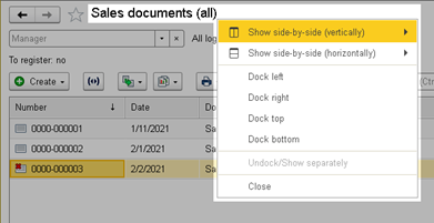
Fig. 61. Form header context menu
- Context menu of an item on the open items panel (see Open items panel). It provides more features to manage the form display than the previous option.
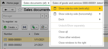
Fig. 62. Context menu of the open items panel
The key difference is that the Show side-by-side with current window... commands are available. They are displayed if the context menu is opened for a respective item of an inactive form. The menu will not contain these items for an active form.
If you use the system command bar button or right-click the form header to open the menu, only commands to merge with the second form are available (the Show side-by-side with another window... commands). If you right-click an item on the open items panel to open the menu, it also includes commands to display the form along with the current form (the Show side-by-side with current window... commands). Then the commands to dock the form to any edge of the work area follows (Dock...). Next is the command to disable docking or side-by-side display.
If the Show side-by-side with another window... command is used, then the current form and the form selected from the menu are displayed side-by-side. If the Show side-by-side with current window... command is used, then the current form and the form on whose presentation the context menu command is used are displayed side-by-side. To simplify the merging process, it is recommended to use the context menu command of the open items panel items.
When you merge or dock forms, the general rule is applied: if the form to be merged or docked is already merged or docked, it is separated or undocked before the selected command is performed.
You can use windows displayed side-by-side when you compare the results of generating reports for different periods or with different settings. To display two forms side by side, do the following:
-
Open the analyzed report form.
-
Open the same report in another window. Use commands of the report form or the context menu of the functions menu item.
-
Set up and generate both of the reports.
-
Merge the forms using any option.
When you merge forms, note the following command features:
-
The Show side-by-side/Dock button commands are unavailable for the home page and the form locking the owner window.
-
When you click Show side-by-side (vertically), a form selected from the submenu is placed on the right side. If you call the command from the context menu not of the current form, this form becomes active.
-
When you click Show side-by-side (horizontally), a form selected from the submenu is placed under the current form. If you call the command from the context menu not of the current form, this form becomes active.
-
A separator is placed between the merged forms so that they have equal width (height).
-
When you activate any of the forms displayed side-by-side, both of the forms are displayed simultaneously.
-
A new form is opened from any of the form displayed side-by-side the same way as from an ordinary form.
-
The Home page, Forward, and Back buttons are always displayed in the left (top) form of the merged form.
-
The home page cannot be displayed side-by-side with another form, except for a docked form.
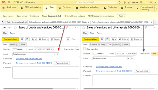
Fig. 63. Side-by-side form display
Another option to display forms side-by-side is to dock a form so that it is always available to the user and is not overlapped by ordinary forms. For example, you can use this display option if there is a data source that must be constantly displayed (report or document journal) and must not be overlapped by other forms opened in the application.
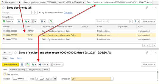
Fig. 64. Docking a form
A form can be docked to any side of the main application window. In fig. 64, the list form of expenditure requests is docked to the top. The other forms are opened at the bottom of the main application window.
To dock a form, select the Dock... command using any suitable option. The docked form occupies 40% of the work area (by default) of the main application window. A separator is placed between the docked form and the rest part of the work area. It allows you to change the docked window size. The separator position (for each side of the main application window) is stored in the settings of the main application window in the system settings storage (see 1C:Enterprise storage).
3.1.2.12. Panel customization
3.1.2.12.1. Manual
The Taxi interface allows you to customize the display and layout of various panels in the main application window. To do this, use Panel editor. To open it, click Service and settings – Settings – Panel settings….
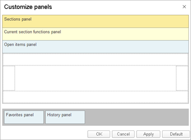
Fig. 65. Panel editor
In the opened editor, you can drag the respective item of the main application window (the lower part of the form highlighted with a gray background) to the required location. Drag items into the light rectangles marked with a gray line. In this case, panels are displayed in different rows or columns. You can drag an item onto an existing item. In this case, items are displayed in the same row or column. The editor center displays the home page work area. You cannot place any panel into this area.
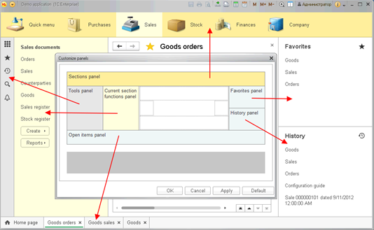
Fig. 66. Panel layout example
To delete an item, drag it from the layout back to the item with a gray background.
You can remove any item, except the work area, from the main application window. For example, you can create a minimalistic application interface with the main window containing only a work area and an open items panel.
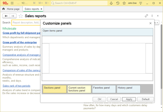
Fig. 67. Minimalistic interface
Click Default to return to the interface state specified by the application developer in the Client application interface configuration property (see Specifying presentation properties).
3.1.2.12.2. Software
You can also customize the display and layout of various panels in the main application window using 1C:Enterprise language. To do it, use the GetContent() and SetContent() methods of the ClientApplicationInterfaceSettings object. So, you can get the current settings of the client application interface, modify them as you need, and set them back.
Client application settings are stored in the standard system settings storage. The settings key is Common/ClientApplicationInterfaceSettings.
To change the settings, first read them from the storage:
Settings = SystemSettingsStorage.Load("Common/ClientApplicationInterfaceSettings");Then you can modify the settings and save them back to the storage:
SystemSettingsStorage.Save("Common/ClientApplicationInterfaceSettings", "", Settings);After you save the new settings, rebuild the client application interface by calling the RefreshInterface() method.
Consider an example when you need to forcibly install a simplified version of the client application interface at each system startup. Such interface version contains only one panel (open items panel) located along the top side of the main application window. To show an example, find a common module with Server and Server Call checkboxes selected. Let the name of the common module is SetupInterface. The common module must include the following procedure:
Procedure MinimalInterface() Export
Settings = New ClientApplicationInterfaceSettings;
ContentSettings = New ClientApplicationInterfaceContentSettings;
ContentSettings.Top.Add(New ClientApplicationInterfaceContentSettingsItem("OpenItemsPanel"));
Settings.SetContent(ContentSettings);
SystemSettingsStorage.Save("Common/ClientApplicationInterfaceSettings", "", Settings);
EndProcedureThe managed application module must include the OnStart event handler:
Procedure OnStart()
SetupInterface.MinimalInterface();
RefreshInterface();
EndProcedureAs a result, regardless of settings made by the user in the previous session, every new session will start with a minimal interface.
3.1.2.13. Closing the application
You can close the application using the next options:
-
Click Exit in Service and Settings – File.
-
Click the hyperlink with the user name on the main panel of the main application window. This hyperlink is not displayed if the infobase contains no list of users.
Fig. 68. Closing the application
When you click the hyperlink with the user name on the main panel, a special menu is displayed. It contains the Full name (which is also displayed on the main panel) and Name property values for the current user and the Exit hyperlink. When you exit the application (using the Service and settings menu or the Exit hyperlink), the following actions are performed:
-
OpenID authentication is canceled (OpenID logout). It happens if the authentication was performed using OpenID.
-
Client application is closed.
When you exit the web client, you can specify which page (specify its URL) will be opened in the web browser after you log out. To do this, specify the URL to open after exiting the web client parameter when you publish the web client. The web client behavior upon exit depends on whether this parameter is specified:
-
If the URL is specified, you navigate to the specified address. If no schema is specified, an HTTP schema is used.
-
If the URL is not specified, you navigate to a special page that allows you to quickly log in to the application again.

Fig. 69. Exiting the web client
You will navigate to the address (URL) specified upon publication in the following cases:
-
If you exit using one of the following commands: Close, Exit, or Log out.
-
If the Exit() global context method is executed with the RestartOnCompletion parameter set to False.
In other cases, you navigate to the about:blank address or the web client is restarted.
3.1.3. Auxiliary window
3.1.3.1. General information
Auxiliary window is an application window where forms created in the application are opened. You can open the auxiliary window both in the work area of the main application window and in a separate window. The opening mode of the auxiliary application window depends on theWindow opening mode form property value (see Forms).
When you close the auxiliary window, it does not close the entire application. The number of open auxiliary windows is not limited but you can open only one auxiliary window for each infobase object, for example, a document or a catalog item. So, you cannot open several windows to view the same document unless it is allowed in the application.
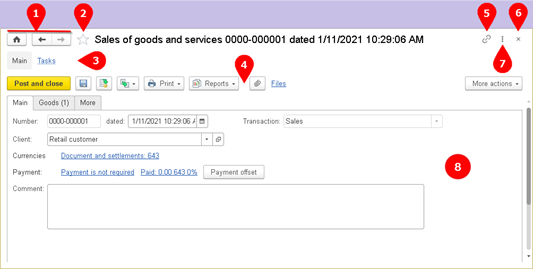
Fig. 70. Auxiliary window structure
In fig. 70, the following items are numbered:
-
Form management buttons. A button to go to home page (the first button on the left) is displayed on the form if the open items panel display is disabled in the panel settings. Buttons for navigation to the previous/next form allow you to navigate through the list of open windows. A button to navigate to the next form is activated only after you click the button to navigate to the previous window at least once.
-
Button to add the form to the favorites list. If the form is not in the favorites list, the star color matches the form background. Otherwise, the star is colored yellow. The button is unavailable if the user does not have theSaveUserData right.
-
Form navigation panel (see Form navigation panel).
-
Form command bar (see Form command bar).
-
Button to get the form URL.
-
Button to close the form.
-
Form menu. To open the form menu, press Alt + –. One form menu is always displayed in the upper right corner of the home page. The form menu is unavailable in dialog boxes displayed using the following methods: DoQueryBox(), ShowQueryBox(), DoQueryBoxAsync(), DoMessageBox(), ShowMessageBox(), and DoMessageBoxAsync.
-
Form work area.
If the current form contains visible fields whose content can be printed, buttons for the Save, Print, and Preview commands are added to the form header.
Fig. 71. Printing in auxiliary form header
The following form fields are visible: spreadsheet document, text document, graphical schema, HTML document, formatted document, geographical schema, and planner.
In the auxiliary window, you can select a default form, which is displayed by default when you open the auxiliary window. The default form is opened when you click the Main item in the form navigation panel. When you click the other references on the form navigation panel, auxiliary forms are opened.
See also:
-
Favorites (see Favorites).
-
Panel settings (see Panel customization).
-
Access rights (see Access rights description).
-
URLs (see URLs).
3.1.3.2. Form navigation panel
The auxiliary window navigation panel (the form navigation panel) allows you to view various details logically related to the data that are displayed in the main window form.
The navigation panel can contain commands of three groups: Important, Go to, and See also. The general command layout is as follows:
-
The first command is always the Main command (highlighted in bold). It opens the main form of the auxiliary application window.
-
Then the Important group commands follow.
-
Then the Go to group commands follow.
-
The last commands are the See also group commands. If the configuration developer defines custom command groups from the Form navigation panel category, the commands of these groups are placed directly before the See also group commands. This group commands are always placed at the very end of the form navigation panel.
If commands do not fit in the navigation panel, the last command will be the More submenu. It will contain all the commands that do not fit in the displayed part of the navigation panel.
To go to the form navigation panel, press Alt + 4. The form navigation panel contains the following keyboard shortcuts:
-
To move to the next/previous panel item, press Tab/Shift + Tab or Right Arrow/Left Arrow. When you reach the first/last panel item, you do not move to the last/first panel item.
-
To move to the first panel item, press Home.
-
To move to the last panel item, press End.
-
To exit the panel navigation mode, press Esc.
3.1.3.3. Form command bar
A form command bar includes the commands that are directly related to the object displayed in the main form. There are standard Important and Generate groups. Besides, the developer can place custom groups on the panel. Each command from the Important group is displayed with its own button on the panel. The Generate group is displayed as a panel submenu. All command groups created by the developer are displayed as a submenu. Form commands, such as Save and close, are placed before the Important group commands.
If a group contains no commands, the group is not displayed. If the configuration developer adds custom groups to this area, they are placed after the Generate group.
If all the command bar commands do not fit in the form, they are placed in the More submenu, which is located at the end of the command bar. If the help is provided for the form, its button is located to the right of the More submenu.
3.1.3.4. Application form scaling
The client application allows you to scale the displayed forms on the screen. The user can change the scale of one or all forms of the application in the range from 50 to 400% relative to the scale specified in Designer. To open the scale dialog box, click Change scale in the form menu.
In the opened dialog box, you can change the scale using the slider and set the specified scale for all the application forms using the Set for all forms dialog box button. You can move the scale dialog box to any place on the screen.

Fig. 72. Scale dialog box
When you change the scale, remember that the scale set in the client application is added to the scale specified in Designer for each form (the ClientApplicationForm.Scale property). If the scale is set to 10% in Designer and it is set to 50% in the client application, the resulting scale will be 5% of the actual form size.
The scale feature is unavailable if the compact display mode is set for the entire application (using the ClientSettings object).
Note. Note. The scaling is possible for managed forms only.
3.1.4. Nonvisual access to interface
3.1.4.1. General information
Screen readers can operate the following form item parts: name, tooltip, form item value, and some others depending on the screen reader. When an item is hovered over, the screen reader reads its name and value. Form item parts may differ depending on the used screen reader. Additionally, the current control state is read: collapsed/expanded (for example, for a drop-down list), set/cleared (for example, for a checkbox field). Item tooltips are also read. An exception is reading of tooltips for buttons and hyperlinks: if the Tooltip display property is set to a value other than Pop up, this tooltip cannot be recognized by the screen reader.
3.1.4.2. Description of form items and UI elements
Sections panel
The Sections panel name is read as Sections panel in the current localization language. The tooltip is set from the Note property of the respective subsystem. The current active section is read, including when you switch sections.Functions menu
The panel name is read as Functions menu in the current localization language. Menu items are grouped. Search results are grouped by subsystems.Form navigation panel
The panel name is read as Form navigation panel in the current localization language. Item names are read according to the references on the Form navigation panel.Button and hyperlink
The control name must match its automatic or overridden title. The tooltip is set from the Tooltip property of the related command or from the extended tooltip of the button. If the Tooltip display property is set to a value other than Pop-up, then this tooltip cannot be recognized by the screen reader.If a keyboard shortcut is specified for the related command of the button, it is recognized.
Calendar
Names of the month cells must match the full date name (including a month and a day). If the Calendar displays more than 1 month, all cells of one month are grouped under the name of the month and the year.The months panel (if it is available) is read as a radio button group. After you select a month, the selected month is read.
Hyperlink today ... is read as a word today and the current date.
Checkbox field
The control name must match its automatic or overridden title. The tooltip is set from a standard or extended tooltip regardless of the display method.Radio button field
The control name must match the automatic or overridden title of each radio button item. For the first radio button item in the group, the name is preceded by the title of the attribute edited by the radio button.Command bar
The Command bar is not read, except for the Service and settings menu. Names, tooltips, and hot keys are read for the Command bar buttons. If the button opens a drop-down list, the screen reader reads the list state (expanded or collapsed).If the command bar opens a menu and the menu items are marked (the Check property), the mark state is read for such buttons.
Input field
The control name must match its automatic or overridden title. If there is a button to open a drop-down list, the list state (expanded or collapsed) is read for the Input field. The tooltip is set from a standard or extended tooltip regardless of the display method. If the Password property is set for a field, the field value is not read.Picture
The item name must match the tooltip without a hot key. The tooltip is set from a standard or extended tooltip regardless of the display method. If a keyboard shortcut is specified for the Picture, it is recognized.Collapsible group
The control name must match its automatic or overridden title. The group state is read: collapsed/expanded.Slider field
The control name must match its automatic or overridden title. The tooltip is set from a standard or extended tooltip regardless of the display method.Radio button field
If a group of radio button fields matches the control, the grouping name must match the automatic or overridden title on managed forms. Radio button field names match their labels. The active item is read as selected. The tooltip is set from a standard or extended tooltip regardless of the display method.Tabs
The current tab is read, including when you switch Tabs.Table
Only columns that can be focused are processed. If there are more than one column to process, this form item is considered a Table. Otherwise, it is considered a list. If the form item is considered a list, its name is set from the column name (if it exists).Table cells are read as CellContent ColumnName. If the reader reads a dynamic list and the current item is marked for deletion, it reads Marked for deletion after the cell content in the current localization language.
If a row is a grouping (if the table displays a tree), the current grouping state (expanded or collapsed) is also read for all its cells.
Spreadsheet document
Spreadsheet document cells are read as CellContent Coordinates, where coordinates completely match the numbering in Microsoft Excel:-
The A1 coordinate corresponds to the cell in the first column of the first row.
-
Columns are coded with letters, rows are coded with numbers.
If a row is a grouping (in grouping mode), the current grouping state (expanded or collapsed) is also read for all its cells.
3.1.4.3. Unmanaged system forms
The following unmanaged forms are read:
-
Dialog box to adjust calculator precision
-
Dialog box to select a font
-
Dialog box to select a color
-
Dialog box to follow a link
-
Dialog box to get a link
-
Dialog box to search in a spreadsheet document
-
Dialog box to search in a text document
-
Dialog box to access an infobase in thin client
-
Dialog box to start the application in thick client
-
Dialog box to start the application in thin client
-
Dialog box to set up the dialog box for starting the application in thick client
3.1.4.4. Restrictions
-
Group titles are not read.
-
Decoration (picture) titles are not read.
-
Input hints (within the input field) are not read.
-
You can move the focus to inactive command bar items, which are not read in this case.
Chapter 4. 1C:Enterprise language
1C:Enterprise is a flexible customizable system to solve a wide range of tasks in the field of business automation. Specific configuration algorithms are described in 1C:Enterprise Designer and in software modules that contain texts in 1C:Enterprise language.
4.1. Purpose and brief description of 1C:Enterprise language
1C:Enterprise language is designed to describe algorithms for an application task at the configuration development stage.
1C:Enterprise language (hereinafter – 'language') is an object-oriented programming language, specially designed to be used not only by professional programmers. In particular, all language operators have both Russian and English variants, which can be used simultaneously in one source text. The primary language described in this book is English. However, you can find Russian synonyms for all mentioned language operators.
Being relatively simple, the language has some object-oriented features. For example, the rules for accessing properties and methods of specialized data types (documents, catalogs, and so on) are similar to the properties and methods of objects used in other object-oriented languages. However, these specialized data types cannot be defined by the language means, but must be set in WYSIWYG mode.
Variable typing in the language is not strict, that is, variable type is determined by its value. Variables do not require explicit declaration. A variable is considered implicitly defined when it first appears to the left of the assignment operator. You can also explicitly declare variables using the appropriate operator. You can use arrays, structures, maps, and other universal value collections.
4.2. Format of module source text
4.2.1. What is a module?
1C:Enterprise configuration modules are not independent programs in the conventional sense, since they are only part of the entire configuration. Module is a text in 1C:Enterprise language that contains texts of procedures and functions with required algorithms. Modules are called by the system at certain moments of its operation. Therefore, the module does not have formal boundaries in its description such as "Beginning of module" – "End of module".
Location of a specific module is provided by Designer at the configuration points where specific operation algorithms must be described. Developers must write such algorithms as procedures or functions that will be automatically called by the system in predefined situations. For example, when you click a button in a dialog box.
Each individual module is processed by the system as a whole. Therefore, all procedures and functions of a module are executed in a single context.
4.2.2. Module execution context
Each module is linked with the rest of the configuration. This link is called the module execution context.
There are two types of the context:
-
Global context
-
Local context to execute a specific module
4.2.2.1. Global context
Global context is defined by:
-
Values of global-context properties and methods.
-
System enumerations and system value sets, for example, DialogReturnCode and Chars.
Global context is visible to all modules and defines a common language environment for the configuration.
4.2.2.2. Local context
Local module context is defined by the specific location of the task, for which the module is called, in the configuration. Local context is visible only to a specific module and defines objects, their properties, and methods accessible to this module.
4.2.3. Module types
1C:Enterprise supports several module types. They differ in their location and available context.
4.2.3.1. Managed application module
Managed application module is a module that is automatically executed when the configuration is loaded at 1C:Enterprise startup in the following modes:
-
Thin client
-
Web client
-
Thick client in managed application mode.
The managed application module is designed to perform actions related to the end-user session (primarily session start and session end processing). The managed application module is not available for procedures running on the server. It is recommended that you implement there only handlers of corresponding events. Remember that an unhandled exception in any event handler of the managed application module (BeforeStart(), OnStart(), BeforeExit(), or OnExit()) can cause an abnormal system termination.
The example below will not result in an abnormal termination:
Procedure OnStart()
Try
a=1/0;
Except
Message("Division
by zero");
EndTry;
EndProcedureAt the same time, the following example results in an abnormal termination:
Procedure OnStart()
a=1/0;
EndProcedureProcedures and functions of the managed application module, as well as variables with the Export keyword in the header, are available:
-
In non-global client common modules.
-
Client procedures and command module functions.
-
Client procedures and functions of the managed form module.
In the context of the managed application module, the following elements are available:
-
Global context part that can be executed in the managed application.
-
Exported procedures and functions of any common client modules.
-
Exported procedures and functions of server non-global common modules where the Server call property is set.
4.2.3.2. External connection module
The external connection module is located, like the application module, in the root section of the configuration. It contains event handler procedures that are initialized at application startup and exit in the external connection (COM connection) mode.
In the external connection module, you can declare variables and also declare and define procedures and functions that will be available to an external application.
The following 1C:Enterprise objects are available from outside via COM connection:
-
Exported procedures and functions of the external connection module.
-
Exported procedures and functions of common modules.
-
Including and excluding entire common modules is performed in their properties.
-
Including and excluding certain parts of common modules is performed using preprocessor commands.
-
-
Global 1C:Enterprise context.
The module is available only in external connection sessions. No user interface is available in this mode.
4.2.3.3. Session module
Session module is a module that is executed automatically at 1C:Enterprise startup, when a configuration is being loaded.
Use the session module to initialize session parameters and perform session-related operations. This common module is always executed in the privileged mode of 1C:Enterprise server. To set session parameters, use the SessionParametersSetting event handler.
A session module can contain only definitions of procedures and functions, can call procedures from common configuration modules, and does not contain exported procedures and functions.
The SessionParametersSetting() handler is called before calling the BeforeStart() event handler (or OnStart() for the external connection module).
When executing the SessionParametersSetting event handler, you might need to determine which session starts: a background job session or another one. It might be required when the amount of background job data being initialized significantly differs from the amount of other session data being initialized. You can determine the session type using the GetCurrentInfoBaseSession() or GetBackgroundJob() methods. The first method returns the InfoBaseSession object that describes the current session. Calling the GetBackgroundJob() method of the received object allows to clearly understand whether a background job session or some other session starts.
4.2.3.4. Common modules
Common modules are located in a dedicated branch of the metadata tree. Common modules are primarily designed to keep general-purpose configuration algorithms accessible from various modules. Common modules do not include the variable definition section or the main program section. They only have the section for procedures and functions (see "Module structure").
In any common module, you can declare and define procedures and functions that you want to be accessible from any configuration module.
For more information on common modules, see Common modules.
4.2.3.5. Applied object modules
Each set of applied objects has a module. Applied objects include:
-
Constant value managers
-
Catalogs
-
Documents
-
Reports
-
Data processors
-
Charts of characteristic types
-
Charts of accounts
-
Charts of calculation types
-
Exchange plans
-
Business processes
-
Tasks
-
Registers
Modules represent object properties. They are located in the configuration branches where respective objects are stored. Each object has a module. In such modules, you can declare variables, procedures, and functions that are accessible from 1C:Enterprise language outside of the object and supplement the object context.
In the module context of an applied object, you can access attributes and tables of this object, as well as its methods and events.
4.2.3.6. Object manager modules
Each applied object has a manager used to manage this object as a configuration object. The manager allows you to create objects and work with their forms and templates. The manager module extends the manager functionality by introducing 1C:Enterprise language procedures and functions. You can describe methods for a configuration object (for example, a catalog) that are related to the actual configuration object instead of a certain database object instance.
The context of a manager module is comprised of:
-
Global context properties and methods.
-
Exported procedures and functions of global common modules (if these modules are compiled on the server).
-
Exported procedures and functions of non-global common modules (if these modules are compiled on the server).
-
Local context of this module.
A manager module cannot have variables or module body.
When functions or procedures of a manager module are declared as exported, you can access them via the object manager.
For example, let us declare a function in the manager module of the Counterparties catalog:
Function GetDebtorsList() Export
...
EndFunctionThe call of this function from the application code will be as follows:
Debtors = Catalogs.Counterparties.GetDebtorsList();4.2.3.7. Form modules
These modules are stored in configuration forms (see Forms). Each form has a module. In such modules, you can declare variables, procedures, and functions that are accessible from 1C:Enterprise language outside of the form and supplement the form context.
The context of a form is comprised of:
-
Local context of this form module with attributes of the form to which the module "belongs".
-
Properties and methods of the ClientApplicationForm object of 1C:Enterprise language.
-
Properties and methods of the form extension defined by the type of the object whose data is stored in the main attribute of the form.
-
Global context, including non-global common modules and exported functions and procedures of global common modules. However, the procedure description in the form module (&AtClient, &AtServer, and so on) must be consistent with the properties set for the common module (Client (managed application), Server, and so on).
-
Exported variables, procedures, and functions of the managed application module.
4.2.3.8. Command modules
In the command module, you can describe actions to be performed by the system at the command call using 1C:Enterprise language. The command module can only contain definitions of procedures and functions. The command module cannot have variables and module body.
The CommandProcessing() handler must be preceded by the &AtClient preprocessor command, since command execution begins there.
The context of client procedures of the command module is comprised of:
-
Global context, including non-global common modules and exported functions and procedures of global common modules. However, the procedure description in the form module (&AtClient, &AtServer, and so on) must be consistent with the properties set for the common module (Client (managed application), Server, and so on).
-
Local context of this command module.
The context of server procedures of the command module is comprised of:
-
Global context properties and methods.
-
Exported procedures and functions of global common modules (if these modules are compiled on the server).
-
Non-global common modules if these modules are compiled on the server. Exportable methods of such modules are available.
-
Server methods of the command module.
In the command module, you can describe methods with the Export keyword. However, they cannot be used outside of this module. Since you cannot access commands from 1C:Enterprise language, their context is unavailable as well.
4.2.4. Module format
Module structure can be divided into the following sections:
-
Variable definition section.
-
Procedures and functions section.
-
Initialization section.
In a specific module any of the sections can be missing.
The variable definition section starts from the module text and ends before the first Procedure or Function statement or any executable statement. This section can contain only variable declaration statements: Var.
The section of procedures and functions starts from the first Procedure or Function statement and ends before any executable statement outside the body of procedure and function description.
The initialization section starts from the first executable statement outside the body of the last procedure or function and ends with the last module entry. This section can contain only executable statements. The initialization section is executed when the module is initialized. Usually, the main program section should contain the variable initialization statements specifying necessary values which must be assigned before the first call of any procedure or function of the module.
The source code of the module can consist of statements and comments.
4.2.4.1. Comments
You can leave comments with various explanations related to module operation directly in the source code of the module. It is recommended that you put enough comments into the source code to fully describe the program algorithm. Comments are skipped when you run a program. In the module text, comments begin with two slash characters (//) and end with the end of the line. This way, you can leave a comment from the beginning of the line or write it after a statement in the same line. You cannot write a statement in the same line after a comment as such statement will be perceived by the system as part of the comment.
A=B; // This is a
comment
// This is a comment,
tooA comment preceding a procedure or function may be used by the context tooltip of Designer. For the comment format and operation procedure, see Context help for module text input.
4.2.4.2. Format of statements
Statements are presented as standard procedure calls, except for the assignment statement (A = B;) and syntax structures of 1C:Enterprise language (For, While, If, and so on). Statements must be semicolon-separated. A statement can take more than one code line. A line can contain an arbitrary number of semicolon-separated statements.
Language statements in a module can be divided into two categories: variable declaration statements and executable statements.
Variable declaration statements create variable names that can be used in executable statements.
Any executable statement can have a label which can be used as a transition point in the Goto statement.
In general, the language statement format is as follows:
~label:Statement[(parameters)]
[AddlKeyWord];Labels are special identifiers starting with a tilde followed by a sequence of letters, numbers and underscore characters. To mark a statement, place a label and a colon before it.
~label:A=B;4.2.4.3. Names of variables, procedures, and functions
The name of a variable, a declared procedure, or a function can be any sequence of letters, numbers, and underscores beginning with a letter or underscore. Newly created names cannot match the reserved words of the language or property, procedure, and function names (including event handler names) directly accessible in the current context. The names of variables, procedures, and functions are case-insensitive.
4.2.4.4. Modules language
1C:Enterprise language is bilingual. Almost all reserved words, value type names, properties, methods, and events have two versions: in Russian and English. Words that have no Russian equivalents are exceptions to the rule. In the text of modules, these names can be freely mixed using Russian and English names without any restrictions.
4.2.4.5. Case sensitivity in module code
Names of variables, properties, methods, procedures, functions, as well as 1C:Enterprise language functions are case-insensitive, you can use both upper case and lower case characters.
4.2.4.6. Reserved words
The following keywords are reserved and cannot be used in user created variable names, configuration object attributes, declared procedures, and functions. In this version of the language, each of the keywords has two presentations: in Russian and in English.
| Russian | English |
|---|---|
| Если | If |
| Тогда | Then |
| ИначеЕсли | ElsIf |
| Иначе | Else |
| КонецЕсли | EndIf |
| Для | For |
| Каждого | Each |
| Из | In |
| По | To |
| Пока | While |
| Цикл | Do |
| КонецЦикла | EndDo |
| Процедура | Procedure |
| Функция | Function |
| КонецПроцедуры | EndProcedure |
| КонецФункции | EndFunction |
| Перем | Var |
| Перейти | Goto |
| Возврат | Return |
| Продолжить | Continue |
| Прервать | Break |
| И | And |
| Или | Or |
| Не | Not |
| Попытка | Try |
| Исключение | Except |
| ВызватьИсключение | Raise |
| КонецПопытки | EndTry |
| Новый | New |
| Выполнить | Execute |
Note. Note. The keywords are not case-sensitive.
4.2.5. Special characters used in source code
| Character | Description |
|---|---|
| // | A double-slash precedes a comment. All the text from this character to the end of the current line is considered a comment. |
| | | It is used only in string constants at the beginning of a line. If a line starts with this character, it is an extension of the previous one (line break). |
| ~ | Starts a statement label. |
| : | Ends a statement label. |
| ; | Statement separator. |
| ( ) | Parentheses enclose parameters of methods, procedures, functions, and constructors. They are also used in 1C:Enterprise language expressions. |
| [ ] | Use square brackets to access object properties by a string presentation of the property name. Collection elements can be called by index or another parameter. |
| , | Separates parameters in the parameter list of methods, procedures, functions, and constructors. |
| " " | Encloses string literals. |
| ' ' | Encloses date literals. |
| . | Decimal point in numeric literals. The separator to refer the properties and methods of 1C:Enterprise language objects. |
| + | Addition. Concatenates strings. |
| - | Subtraction |
| * | Multiplication |
| / | Division |
| % | Remainder of division. Dividend and divisor can be fractional values. |
| > | Logical operation Greater than |
| >= | Logical operation Greater than or equal to |
| < | Logical operation Less than |
| <= | Logical operation Less than or equal to |
| = | Assignment. Logical operation Equal to |
| <> | Logical operation Not equal |
4.3. Data types and variables
4.3.1. General information
Type determines a set of values that is specific for this type of data and a set of operations that can be performed on values of this type. Variable is a reference to an area in the memory that stores a value of a certain type. A value does not change its type since the time of creation. The name variable identifies a variable. Since dynamic data typing is used in 1C:Enterprise, a variable can refer to values of different types at each specific point in time. If no value is defined for a variable before using it, such variable contains the Undefined value. In 1C:Enterprise, everything is an object. In other words, a value of any type is an object including the Type type value. Words "value" and "object" may be used synonymously in the documentation. Considering this, a variable contains a link to an object or a value. Therefore, "a variable value" can be perceived as an object located somewhere in the RAM, the link to which is stored in the variable.
There are two data types: mutable or changeable and immutable or unchangeable. The immutable type is a type whose object state cannot be changed after the value is created. The subset of immutable types includes primitive types such as Undefined, NULL, Number, Date, String, and Boolean. For example, if an operation is performed with the Number type value, a new Number type value is created, but the already existing object is not modified. At the same time, another example of mutable type is a type that describes a catalog item (for more information, see Catalogs). The mutable type allows you to change the state of an object of this type without creating a new object. Another difference between objects of mutable and immutable types is how they are compared:
-
Immutable type values are compared "by value". For that reason, different variable values of the Number type will be the same if the same number value is used to create each value.
-
Mutable type values are compared "by reference". In other words, memory addresses where such values are located are compared. Therefore, two mutable type values are never equal to each other, even if they refer to the same data item, for example, to a catalog item with the same reference. The mutable type value is equal to itself only.
Another thing worth mentioning is the definition of reference type data. Reference type data does not store an object value. It contains only a certain key that allows retrieving a value from the database. Retrieving an object via a reference is called dereference. A reference type name contains the Ref term: CatalogRef, EnumRef and so on. The reference type is immutable.
The primitive 1C:Enterprise types are described further in this section. The mutable types are described in other chapters and sections of this manual. For all primitive data types, you can use literals in the module text, that is, you can specify values of the matching type directly in the module.
// Example of a String
type literal
A = "My
string";
// Example of a Boolean
type literal
B = True;
// Example of a Number
type literal
В = 12345.6789;4.3.2. NULL
Description:
Values of this type are used only to specify a missing value in database operations, for example, when joining tables.Literals:
NULL
4.3.3. Boolean
Description:
Variables of this type have two values defined by the respective literals: True and False. Values of this type are returned as a result of evaluating logical expressions.Note.
The 1C:Enterprise language comparison operations use logical expressions. This means that a comparison expression does not have to look as follows:
If MyVariable = True Then
EndIf;The following is enough:
If MyVariable Then
EndIf;Literals:
-
True
-
False
4.3.4. Date
Description:
Values of this type contain an AD date (starting from January, 1 0001) and a time accurate down to the second. The value of the Date type stored in the variable contains an AD date with accuracy up to 100 microseconds. In the database, the value is stored with accuracy up to 1 second. It is not recommended that you use numeric values with fractional part in arithmetic operations with dates.Literals:
A string of numbers enclosed in single quotes of the form 'YYYMMDDhhmmss', where:
-
YYYY is a 4-digit number of year
-
MM is a 2-digit number of month
-
DD is a 2-digit number of day
-
hh is a 2-digit number of hour (in 24-hour format)
-
mm is a 2-digit number of minute
-
ss is a 2-digit number of second
A literal of the Date type must contain year, month, and day. You can omit seconds or the entire time. If seconds are not specified, they are set to 0. A starting date is '00010101'. All characters other than digits are ignored in the date literal. You can place separators in the date literal to simplify its presentation.
Example:
Date('2017/03/23
10~45~25') = 23.03.2017 10:45:25
Date(2017, 03, 23, 10, 45, 25) = 23.03.2017 10:45:25
Date('2017.03.23
10:45:25') = 23.03.2017 10:45:25
Date('20170323104525')
= 23.03.2017 10:45:254.3.5. Undefined
Description:
The value of this type is used when you need to use an empty value that does not belong to any other type. For example, union type attributes initially have such values. Values of this type are represented by a single literal.Literals:
Undefined
4.3.6. String
Description:
Values of this type contain a string of arbitrary length in Unicode format. The string is encoded in UTF-16 format.If you need to specify a surrogate pair in the string, use two calls of theChar() function, specifying the value of each code unit from the surrogate pair in turn.Literals:
String literals are a set of characters enclosed in quotes. To include the quote character in the string, you need to type two quotes in a row ("").
In addition, you can use "multiline" string constants. In the source code, multiline constants can be specified in two ways:
-
Between fragments representing individual lines of a multiline string, no characters except for spaces, line breaks and comment lines can be inserted.
-
Each individual fragment must not end with a quotation mark. Each following line must start with a hyphenation character "|" (vertical bar). In this variant, comments are allowed if the line starts with the comment character "//".
Example:
// String example
MyString = "This
is a valid string";
// Example 1: Multiline
string
MyMultilineString = "This is
|a valid
|multiline
|string";
// Example 2: Multiline
string
MyMultilineString = "This is" // This is a comment
"a valid"
"multiline"
"string";
// Example 3: String
containing quotes
CompanyName = """Cornflower"" LLC"
// Example 4: Surrogate pair
TextWithSurrogatePair = "Hieroglyph: " + Char(55401) + Char(56997);CompanyName from Example 3 is displayed and printed as follows:
"Cornflower" LLC4.3.7. Type
Description:
Values of this type are used to identify types of values. This is necessary to define and compare types. This type has no literals and is returned by the TypeOf() and Type() 1C:Enterprise language functions.4.3.8. Number
Description:
The numeric type can represent any decimal number. The basic arithmetic operations on data of numeric type are: addition, subtraction, multiplication, and division.Note. IMPORTANT. The maximum digit capacity of a number is 32 characters.
Literals:
A set of digits specified directly in the module code:
[+|-]{0|1|2|3|4|5|6|7|8|9}[.{0|1|2|3|4|5|6|7|8|9}]
Integer and fractional parts are dot-separated.
Example:
A = 15;
B = –968.612;4.3.9. Converting values to a string and back
Any value in 1C:Enterprise has a text presentation. Presentations of some objects are set in the platform and cannot be changed (for example, system enumerations). For some objects, you can manage presentations using object properties or 1C:Enterprise language properties (for example, catalogs). For other objects, presentations depend on the current session language (for example, numbers, dates, Booleans). A value is automatically converted to its presentation when the value is displayed to the user or assigned to an object of the String type. In this case, a value is implicitly converted to the String type. You can explicitly invoke such conversion. To do this, use the constructor of String type object, passing it the required value as a parameter.
Note that values of some types can be converted in the opposite direction: from a string to a value of the corresponding type. These types include: String, Number, Date, and Boolean. Let's look at how values of these types are converted to strings and back, and what influences the conversion.
String is the simplest type here as it does not imply any conversion.
To convert the Number, Date, or Boolean to a string, specify exact conversion parameters for the Format() function or set regional infobase settings. Regional settings change the presentations of the above types immediately and everywhere in the client application. Thus, the same value that is converted into a string will give a different value as a result, which depends on the regional settings or the client interface (localization) language.
For example, the True value for the Boolean type is set to Да in the Russian interface and Yes in the English interface. If a presentation of the Boolean type value is overridden to, for example, Non (for False) and Oui (for True) in the regional settings dialog box, these values will be displayed in any localization language.
The same applies to the Number and Date types. Either the presentation defined by the session settings or specified localization parameters are used.
Reverse conversion (from a string to a value of the Boolean, Number, or Date type) is more complex. A string can take a converted value in canonical or localized form. Canonical form fully matches the corresponding type presentation as 1C:Enterprise language literals. A localized form is obtained when converting the value into a string, considering regional settings. So, the "value -> string -> value" conversion generally will not work if the localization in the first conversion differs from the localization in the second conversion or if the localization settings differ. Let's consider an example of the Boolean type, but first take a look at a table which contains canonical presentations for each type:
| Type | Canonical presentation |
|---|---|
| Boolean | True value: Истина, True. False value: Ложь, False. For more information, see NULL. |
| Number | A decimal number that can have a sign ("-" or "+") as a prefix, and in which the optional fractional part is separated from the integer part by the "." character. For more information, see Number. |
| Date | A presentation that matches the presentation as a 1C:Enterprise language literal. For more information, see Date. |
If we convert the True value in the string for Russian localization, we will get the Да value. If we try to perform the reverse conversion with English localization, we will get a runtime error. If the presentation of the Boolean type value is changed in the regional infobase settings, exactly the same situation happens. Let's take the Non and Oui example above. If you try to perform the reverse conversion for the Yes or Да string, the same runtime error will occur.
This leads us to several important conclusions:
-
For maximum portability, do not use localizable value presentations when serializing values into text formats manually. You can use the XMLString() and XMLValue methods.
-
When saving values as a text and when it is necessary to restore these values from 1C:Enterprise language, do not change the regional infobase settings after the values are saved. Otherwise, it will be impossible to read these values.
-
Localized default values are not the correct value to convert from a string if the corresponding regional settings sections are changed.
See also:
- Regional infobase settings.
4.4. Assignment statement
Assignment statement (=)
Description:
The assignment statement (the "=" character) means the assignment of the value <Source> to a variable <Destination>.Assigning a value to an undeclared variable that matches a property name available in the current context may result to runtime error or configuration check error. To avoid errors, it is recommended that you explicitly declare variables with such names using the Var statement.
Syntax:
<Destination> = <Source>;Parameters:
<Destination>
The destination can be a variable or a property of 1C:Enterprise language object that can be written.
<Источник>
The expression whose value must be assigned.
Example:
A = B;
Page1 = "777";
DocumentDate = '20020717';4.5. Language expressions
Expression is a mathematical, logical, or string formula that consists of respective operations to calculate a value. A mathematical and logical expression can appear to the right of the equal sign in assignment statements. It can also be a parameter of procedures or functions. A logical expression can also be a condition in the If, While, and For control directives. Expressions consist of constants, variables, and functions joined by symbols of logical and/or arithmetic operations.
4.5.1. Arithmetic operations
The language defines the following types of arithmetic operations.
| Name | Expression |
|---|---|
| Addition | (Op1 + Op2) |
| Subtraction | (Op1 – Op2) |
| Multiplication | (Op1 * Op2) |
| Division | (Op1 / Op2) |
| Remainder | (Op1 % Op2) |
| Unary minus | (-Op1) |
Arithmetic operations have one or two operands whose types determine the operation semantics. The semantic variant of the operation is determined by the first operand. If the type of the second operand does not correspond to the required type, its value is converted to the required type according to the type conversion rules. If the type of the first operand does not correspond to any of the valid types, then depending on the situation, its type might be converted or an execution error might occur.
| Operation | Action description |
|---|---|
| Addition is defined for the following types of operands. | Number + Number Date + Number (the number of seconds is added to the date) |
| Subtraction is defined for the following types of operands. | Number – Number Date – Number (the number of seconds is subtracted from the date) Date – Date (the result is the number of seconds between the dates) |
| Multiplication | Number * Number |
| Division | Number / Number |
| Remainder | Number % Number |
When performing arithmetic operations with theDate type, remember that the result is accurate to 4 decimal places (time is accurate to hundreds of microseconds). However, when you write such value to a database (in the attribute of respective type), the fractional part of the number is discarded. Therefore, it is recommended that you round up values of the Number type to integers in arithmetic operations with values of the Date type.
4.5.2. Concatenation
Concatenation ("+") is used to append one string to another. The length of the resulting string is equal to the sum of lengths of joined strings. If the second or subsequent operands are not of the string type, their values are converted to the string type according to the type conversion rules.
FullName = FirstName + " " + MiddleName + " " + LastName;4.5.3. Logical operations
The logical operation compares operands and generates a Boolean value: True or False. There are two types of logical operations: comparison operations and Boolean operations. In comparison operations two values are compared. Boolean operations are performed on Boolean type values by implementing the Boolean algebra. Symbols of Boolean operations can be combined to form compound operations.
Comparison operations:
The language defines the following types of comparison operations.
| Operation | Expression |
|---|---|
| Greater than | Op1 > Op2 |
| Greater than or equal to | Op1 >= Op2 |
| Equal to | Op1 = Op2 |
| Not equal to | Op1 <> Op2 |
| Less than | Op1 < Op2 |
| Less than or equal to | Op1 <= Op2 |
Comparison operations are defined for the following types of operands.
| Operation | Expression |
|---|---|
| Greater than | Number > Number Number > Boolean String > String Date > Date |
| Greater than or equal to | Number >= Number Number >= Boolean String >= String Date >= Date |
| Less than | Number < Number Number < Boolean String < String Date < Date |
| Less than or equal to | Number <= Number Number <= Boolean String <= String Date <= Date |
| Equal to | Any type = Any type |
| Not equal to | Any type <> Any type |
IfNumber and Boolean type values are compared, the Boolean type value is converted to the Number type according to the following rules:
-
True is converted to 1.
-
False is converted to 0.
After that, values of the Number type are compared.
Boolean operations:
The language defines the following types of Boolean operations.
| And | conjunction (Boolean And) |
| Or | disjunction (Boolean Or) |
| Not | logical negation (Boolean negation Not) |
Logical expressions are evaluated from left to right.Use parentheses to avoid ambiguity and control the sequence of operands.
Levels of priority for logical operations:
| Level 1 | operands in parentheses |
| Level 2 | Not |
| Level 3 | And |
| Level 4 | Or |
Note. Note. When evaluating a logical expression, only required expression parts are evaluated. For example, in the expression(Price > 0) And CheckAmount(), if Price <= 0 the CheckAmount() function is not called.
4.5.4. Priorities for evaluating 1C:Enterprise language expressions
The following table lists 1C:Enterprise language operators in order of increasing priority. Operators with the same priority are calculated from left to right.
| Operation | Description |
|---|---|
| Or | Logical addition |
| And | Logical multiplication |
| Not | Logical negation |
| <, <=, =, >=, >, <> | Comparison |
| +, – | Addition, subtraction |
| *, /, % | Multiplication, division |
| -,+ | Unary plus and minus |
| .,() | Dereferencing, method call, and so on. |
Use parentheses to avoid ambiguity and control the sequence of operands.
4.6. Statements and syntax structures
4.6.1. Declaring variables
Description:
Explicitly declares a variable.Syntax:
Var <Variable name 1> [Export] [, <Variable name 2>, …];Parameters:
<Variable name 1>[, <Variable name 2>, …]
Specifies name(s) of declared variable(s).
Export
Optional keyword. Indicates that this variable is available when accessing the context of this module from other modules. This keyword must be specified for each declared variable separately. It is meaningless when declaring variables of separate procedures or functions.
Example:
// Example of single
variable declaration
Var A
Export;
Var
B;
// Example of several variables’
declaration in a single statement
Var A, B Export;Implicit variable declaration:
You do not have to declare variables explicitly. The first time a variable is specified before an assignment operator, it is considered implicitly declared. The variable type is determined by the type of value assigned to it. Variables that were not previously explicitly or implicitly declared cannot be used in expressions.
Variable scope:
The scope of variables depends on where they are declared in the configuration. There are three areas where variables can be declared:
-
In the variable declaration section of the managed application module. These variables are global.
-
In the variable declaration section of a module. These are module variables.
-
In a procedure or function. These variables are local.
Global variables declared with the Export keyword are available for use in executable statements, expressions, in any procedure or function of any custom module of the configuration.
Module variables are available for use in executable statements, expressions, in any procedure or function of the module where they are declared. If they are declared with the Export keyword, they are available from other modules via the context of the module where they are declared.
Local variables are available within the procedure or function where they are declared.
If a variable is defined as global, then it is visible from all the procedures and functions of any custom module of the configuration. If a variable is defined in a procedure or function, its scope is this procedure or function.
This way, if two variables with the same name are used in two different procedures of a module and the names of these variables are not declared as global, those are two different variables local within their procedures. If a variable is declared as global, any use of its name calls the same variable.
The only way to create a local variable in a procedure with a name of an already existing global variable is to declare such local variable explicitly using the Var statement.
4.6.2. Creating new objects
Description:
This statement allows you to create a value of a specific type. It can be used only for those types that allow creation of new values. For applied objects, use the functional form of the New statement (option 2), since when checking modules in Designer, the types for applied objects are not defined yet.When using the functional form of the New statement, consider that dereferencing cannot be applied directly to the statement result. At first, assign the result of the New statement to a variable to further use this variable.
Syntax (option 1):
New <Type name>[(, ..., )]Parameters:
Type name
Specify the name of the type whose value is created.
, ..., <Param N>
If parameters are defined in constructors for this type, they can be specified after the type name enclosed in parentheses. The valid number of parameters and their purpose are specified in the description of object constructors.
Example:
// Example of creating an array of three elements.
Array = New Array(3);Syntax (option 2):
New (<Type>[, <Constructor parameters>])Parameters:
Type
Type name or value of the Type type.
<Constructor parameters>
An array of constructor parameters.
Example:
ValueType = Type("StringQualifiers");
Parameters = New Array(2);
Parameters[0] = 20;
Parameters[1] = AllowedLength.Variable;
StrQualif = New(ValueType, Parameters);4.6.3. Procedure
Description:
The Procedure keyword denotes the beginning of a code snippet that can be called from any module point by calling the ProcedureName() function with a list of parameters. Parentheses are required even if no parameters are passed. In an application module or common module, a procedure is accessible from all configuration modules if the Export keyword is specified in its body.When the Return statement is executed, the procedure ends and returns control to the call point. If the Return statement is not specified in a procedure, the statement is executed implicitly after the last executable statement. The EndProcedure statement denotes the end of the procedure.
Variables declared in the local variable declaration section of the procedure body are local variables and therefore accessible in this procedure only, except when they are passed as parameters for calling other procedures, functions, or methods.
Note. Note. The Procedure and EndProcedure keywords are not statements, but statement brackets. Therefore, they must not end with a semicolon to avoid module execution errors.
Syntax:
[Async ]Procedure <ProcedureName>([[Val] <Param 1> [=<DefValue>], ... ,[Val] <Param N> [=<DefValue>]])[Export]
// Local variables declaration;
// Statements;
...
[Return;]
// Statements;
...
EndProcedureParameters:
<ProcedureName>
Specifies the procedure name.
Async
Means that an asynchronous procedure where the Await statement can be used is described. It is available when describing client procedures including client event handlers. For more information on how to use asynchronous methods and the Await statement, see Synchronous and asynchronous operations.
Val
An optional keyword. The parameter that follows the keyword is passed as a value. Therefore, changing the value of the formal parameter during the procedure execution does not affect the actual parameter that is passed upon the procedure call. If this keyword is not specified, the procedure parameter is passed as a reference. Therefore, changing the formal parameter value inside the procedure changes the actual parameter value.
If an asynchronous procedure is described, the Val keyword is ignored (if any). Asynchronous method parameters are always passed by value. For more information on asynchronous methods, see Features of asynchronous methods.
, ..., <Param N>
Optional comma-separated list of formal parameters. Formal parameter values must match the values of actual parameters that are passed upon the procedure call. This list contains the parameter names that are used in the procedure text. The list of formal parameters can be empty.
=<DefValue>
An optional default parameter value. You can include parameters with default values anywhere in the list of formal parameters. For more information, see Passing procedure and function parameters.
Export
An optional keyword that specifies that this procedure is accessible from other modules.
// Local variables declaration
Declarations of local variables that can be referenced in this procedure only (see Var operator description).
// Statements
Executable statements of the procedure.
Return
An optional keyword that ends the procedure and returns to the code point where the procedure was called. The use of this operator in the procedure is optional.
EndProcedure
Required keyword that identifies the end of procedure. Returns to the code point where the procedure was called.
Example:
Var Glob;
// The procedure definition
Procedure MyProcedure(Par1, Par2, Par3) Export
Glob = Glob + Par1 + Par2 + Par3;
Return;
EndProcedure
Glob = 123;
MyProcedure (5, 6, 7); // Procedure call4.6.4. Function
Description:
The Function keyword denotes the beginning of a function code that can be called from any module point by specifying the FunctionName() function with a list of parameters. Parentheses are required even if no parameters are passed. In an application module or common module, a function is accessible from all configuration modules if it contains the Export keyword in its body.Function execution ends with the Return statement. Unlike procedures, functions return ReturnValue. The EndFunction statement denotes the end of the function.
Any function in the module source code can be called like a procedure, that is, the language allows not to accept a return value from the function.
If the Return keyword is not specified in the function body or the module line containing the statement is not executed, the function returns a value of the Undefined type.
The variables declared in the local variable declaration area of the function body are local variables and therefore accessible in this function only (except when they are used as parameters for calling other procedures, functions, or methods).
Note. Note. The Function and EndFunction keywords are not statements, but statement brackets, so they must not end with a semicolon to avoid module execution errors.
Syntax:
[Async ]Function <FunctionName>([[Val] <Param 1>[=<DefValue>], ... ,[Val] <Param N>[=<DefValue>]])[Export]
// Local variables declaration;
// Statements;
...
Return <ReturnValue>;
// Statements;
...
EndFunctionParameters:
<FunctionName>
Specifies the function name.
Async
Means that an asynchronous procedure where the Await statement can be used is described. It is available only when describing client functions. An asynchronous function always returns an object of the Promise type as a result regardless of the actual return value type. The promise is executed (the actual function result is received) using the Await statement. For more information on how to use asynchronous methods and the Await statement, see Synchronous and asynchronous operations.
Val
An optional keyword. The parameter that follows the keyword is passed as a value. Changing the value of the formal parameter during the function execution does not affect the actual parameter that is passed upon the function call. If this keyword is not specified, the function parameter is passed as a reference. Changing the formal parameter value inside the function changes the actual parameter value.
If an asynchronous function is described, the Val keyword is ignored (if any). Asynchronous method parameters are always passed by value. For more information on asynchronous methods, see Features of asynchronous methods.
, ..., <Param N>
Optional comma-separated list of formal parameters. Formal parameter values must match the values of actual parameters that are passed to the function. This list contains the parameter names that are used in the function source code. The list of formal parameters can be empty.
=<DefValue>
An optional default parameter value. You can include parameters with default values anywhere in the list of formal parameters. For more information, see Passing procedure and function parameters.
Export
An optional keyword that specifies that this function is accessible from other modules.
// Local variables declaration
Declared local variables can be referenced in this function only (see the Var statement description).
// Statements
Executable statements of the function.
Return <Return value>
The keyword that terminates the function and returns the specified value to the expression from which the function is called.
The return value can be an expression or a variable whose value contains the function call result.
EndFunction
A keyword that denotes the end of the function.
Example:
Var Glob;
// The function
definition
Function MyFunction(Par1, Par2, Par3) Export
Glob = Glob + Par1 + Par2 + Par3;
Return Glob;
EndFunction
Glob = 123;
Res = MyFunction(5, 6, 7); // The function call4.6.5. Conditional statements
4.6.5.1. "If" statement
Description:
The If statement controls program execution based on the result of one or several logical expressions. The statement can contain any number of statement groups provided in ElsIf – Then pairs.Syntax:
If <Logical expression> Then
// Statements
[ElsIf <Logical expression> Then]
// Statements
[Else]
// Statements
EndIf;Parameters:
<Logical expression>
Logical expression.
Then
Statements following the Then keyword are executed if the logical expression result is True.
// Statements
One or several executable statements.
ElsIf
The logical expression following the ElsIf keyword is executed only when all the conditions in the If clause and all preceding ElsIf clauses are False. Statements following the ElsIf – Then pair are only executed when the logical expression result in this ElsIf clause is True.
Else
Statements following the Else keyword are executed when all the conditions in the If clause and all preceding ElsIf clauses are False.
EndIf
A keyword that ends the conditional execution block.
Example:
If WeekDay(CurrentDate()) = 6 Then
Report("Today
is Saturday.");
ElsIf WeekDay(CurrentDate()) = 7 Then
Report("Today
is Sunday.");
Else
Report
("Today is a working day.");
EndIf;4.6.5.2. Expression evaluation by condition
Description:
Allows you to evaluate one of two specified expressions depending on the evaluation result of a logical expression.Syntax:
?(<Logical expression>, <Expression 1>, <Expression 2>)Parameters:
<Logical expression>
A logical expression whose evaluation result determines one of the resulting expressions to be evaluated. If its evaluation result is True, <Expression 1> is evaluated. If the result is False, <Expression 2> is evaluated.
<Expression 1>
The expression to be evaluated if the logical expression result is True.
<Expression 2>
The expression to be evaluated if the logical expression result is False.
Return value:
The evaluation result of one of the resulting expressions.
Example:
Status = ? (GetDiscount() > 10, "Special
customer", "Regular customer");
DoMessageBox(Status);4.6.6. Loops
4.6.6.1. "For" loop
Description:
The For loop statement is used to iterate statements inside the Do – EndDo structure. Before the loop starts, the value of <Expression 1> is assigned to the <Variable name> variable. The value of <Variable name> is automatically increased after each loop iteration. The counter increment for each loop iteration is 1. The loop is executed until the value of the variable <Variable name> is less than or equal to the value of <Expression 2>. The loop condition is always checked first, before the loop execution.Syntax:
For <Variable name> = <Expression 1> To <Expression 2> Do
// Statements
[Break;]
// Statements
[Continue;]
// Statements
EndDo;Parameters:
<Variable name>
Variable ID whose value is automatically increased by 1 each time the loop is repeated. It can be referred to as a loop counter.
<Expression 1>
Numeric expression that specifies the initial value assigned to the loop counter on the first loop execution.
To
Syntax link for the <Expression 2> parameter.
<Expression 2>
The maximum value of the loop counter. When the <Variable name> variable becomes greater than <Expression 2>, execution of the For loop statement terminates.
Do
Statements following the Do keyword are executed while the value of the <Variable name> variable is less than or equal to the value of <Expression 2>.
// Statements
One or several executable statements.
Break
Allows you to interrupt the loop at any point. Once this operator is executed, control is passed to the statement after the EndDo keyword.
Continue
Immediately passes control to the loop start where loop execution conditions are evaluated and checked. The remaining statements in the loop body are not executed during this loop iteration.
EndDo
A keyword that ends the loop statement block.
Example:
// Loop on the current month days
LastDayOfMonth = Day(EndOfMonth(CurrentDate()));
For CrntDay = 1 To LastDayOfMonth Do
Status("Now
processing day: "+ CrntDay);
// Statements
to process the next day of the month
// . . .
EndDo;4.6.6.2. "For each" loop
Description:
The For each loop allows you to traverse elements of value collections. At each loop iteration, a new collection element is returned. Traversing is carried out until all collection elements are processed or it can be terminated by the Break statement.Syntax:
For each <Variable name 1> In <Variable name 2> Do
// Statements
[Break;]
// Statements
[Continue;]
// Statements
EndDoParameters:
<Variable name 1>
Variable that is assigned the value of the next collection element on each loop iteration.
In
Syntax link for the <Variable name 2> parameter.
<Variable name 2>
Variable or expression that represents the collection. Elements of this collection are assigned to the <Variable name 1> parameter.
Do
Statements following the Do keyword are executed until all collection elements are processed.
// Statements
One or several executable statements.
Break
Allows you to interrupt the loop at any point. Once this operator is executed, control is passed to the statement after the EndDo keyword.
Continue
Immediately passes control to the loop start where loop execution conditions are evaluated and checked. The remaining statements in the loop body are not executed during this loop iteration.
EndDo
A keyword that ends the loop statement block.
Example:
// Traverse table rows of a document.
Document = Documents.SalesInvoice.FindByCode(12345);
// Check if the document is found
If Not Document.Empty() Then
For Each
ContentRow In Document.Content Do
Status("Row:
" + Document.Content.Index(ContentRow)+1);
// Processing
statements for the next table row
... EndDo;
EndIf;4.6.6.3. "While" loop
Description:
The While loop statement is used to iterate statements inside the Do – EndDo structure. The loop is iterated as long as its logical expression is True. The loop condition is always checked first, before the loop execution.Syntax:
While <Logical expression> Do
// Statements
[Break;]
// Statements
[Continue;]
// Statements
EndDoParameters:
<Logical expression>
Logical expression.
Do
Statements following the Do keyword are executed as long as the logical expression is True.
// Statements
One or several executable statements.
Break
Allows you to interrupt the loop at any point. Once this operator is executed, control is passed to the statement after the EndDo keyword.
Continue
Immediately passes control to the loop start where loop execution conditions are evaluated and checked. The remaining statements in the loop body are not executed during this loop iteration.
EndDo
A keyword that ends the loop statement block.
Example:
DocSelection = Documents.SalesInvoice.Select();
// Traverse all documents
While DocSelection.Next() Do
// Display the
document in the status bar
Status("Process
document #" + DocSelection.Number);
// Statements
to process the document
EndDo;4.6.7. Unconditional Goto
Description:
Pass control to another program statement unconditionally. Passes control from one statement to another.The statement scope is within a module, procedure, or function. Control cannot be passed beyond the limits of a module, procedure, or function.
Note. Note
- The label in this statement cannot be a label of the Procedure or Function statement.
Note. Note 2. The unconditional Goto statement cannot be used to pass control to statements inside the following structures from outside: While – EndDo, For – EndDo, For each – EndDo, If – EndIf, and Try – Except – EndTry.
Syntax:
Goto <Label>;Example:
Goto ~Label1;
... ~ Label1: Message("Transition to the label is
performed.");4.6.8. Executing a code snippet
Description:
Allows you to execute a code snippet that is passed to it as a string value.Note. IMPORTANT. This method is not recommended for implementation of multiple parts of application functionality.
Note. Note. The executable code cannot contain additional procedures or functions, since the code is executed within the procedure or function where this statement is specified. Also, variables cannot be explicitly declared there.
Syntax:
Execute(<String>)Parameters:
<String>
String with code text to execute.
Example:
// Displays the current date in the message window
Execute("Message(CurrentDate())");4.6.9. Waiting for asynchronous function completion
Description:
The Await statement waits for execution of an asynchronous 1C:Enterprise language function. While waiting, execution of the current method is interrupted and control is passed to the calling code. At the same time, the call stack item of 1C:Enterprise language associated with the suspended method is neither cleared nor deleted. Once waiting is completed, execution restarts from the point it was suspended. Besides, it restores the environment state at the moment of suspension including values of local variables.The Await statement is executed as follows:
-
Method execution is paused.
-
When paused for the first time, control will be returned to the code that initially called the current method. For subsequent pauses, control will be returned to the system code that resumed the execution.
-
The method is resumed as soon as Promise is completed. The Await statement returns a value or throws an exception.
Syntax:
[Purpose = ]Await <Promise>;Parameters:
Promise
Value of the Promise type. The value is an object that is returned by an asynchronous 1C:Enterprise function.
Return value:
Return value of an asynchronous function in case of its successful completion. Exception if an exception occurred upon executing an asynchronous function.
Example:
FilesList = Await FindFilesAsync(Await
TempFilesDirAsync(), MaskAllFiles(), False);See also:
- Asynchrony via promises (see Asynchrony via promises).
4.6.10. Operations with exceptions
4.6.10.1. General information
Some errors might occur when the client application is running. They can be data or algorithm errors, errors in third-party software (for example, a DBMS error), or physical environment errors (for example, network errors). Errors can also be called exceptions. In some contexts, the terms "exception" and "error" can be used as synonyms.
In 1C:Enterprise, you can:
-
Throw an exception from the code in 1C:Enterprise language using the Raise statement.
-
Catch errors, if necessary and possible. To do this, use the Try … Except statement.
-
Get error information, analyze the exception stack, and identify exception category from the list.
-
Configure error message texts and generate error reports.
-
Catch any error messages to display error information and generate an error report.
This section describes 1C:Enterprise features for generating and catching exceptions. For more information on the error details processing tools and how to set up error presentation, see Runtime errors.
4.6.10.2. Raising an exception
Description:
If you use the Raise statement, a new exception is raised. The statement can have two syntax options: with one parameter (syntax option 1) or several parameters (syntax option 2). If you need to specify more than one parameter, use the functional statement form.Syntax (option 1):
Raise <Expression>Parameters:
<Expression>
The expression evaluation result is converted to a string that will be used as the exception description.
Example:
Raise "The
document can not be posted";Syntax (option 2):
Raise(<Expression>, <Category>, <Code>, <AdditionalCause>, <Cause>)Parameters:
<Expression>
The expression evaluation result is converted to a string that will be used as the exception description.
<Category>optional
Specifies an error category to which the exception to throw belongs. The category will be displayed to the user. The parameter can only take a value of the ErrorCategory system enumeration. You cannot use the following error categories: AllErrors, OtherError, ScriptCompileError, ScriptRuntimeError, and ExceptionRaisedFromScript. An exception thrown using the functional form of the Raise statement, except for the category in the parameter, will belong to the ScriptRuntimeError and ExceptionRaisedFromScript categories.
To throw an exception from an application in 1C:Enterprise language, it is recommended that you specify a category of the exception to throw. The specified category must match the error to be generated. The error display depends on its category. So, if you specify a category correctly, it allows the user to understand the error cause better.
<Code>optional
An arbitrary value of the String type. It can be used in error handlers to classify exceptions. Error code generation rules and codification principles are within the competence of application developers.
<AdditionalCause>optional
A value of the String type that contains additional information about an error to be generated.
<Cause>optional
When an error occurs due to another exception, specify the exception description in this parameter. The value type is ErrorInfo.
Example:
Raise ("The
document can not be posted", ErrorCategory.ConfigurationError, "ERR.DOCS.0001", "Shipment is not allowed to the client");4.6.10.3. Exception handling
Description:
The Try statement manages the code execution based on errors (exceptions) that arise during module execution and defines how these exceptions are handled.Errors (exceptions) originate from module runtime errors. User-defined exceptions are not supported.
If a runtime error occurs during execution of a statement sequence, execution of the statement that caused the error is stopped and control is passed to the first statement from the exception statement sequence. Control is passed even if the error is caused by a statement within a procedure or function called from the Try statement. If an error occurs in a called procedure or function, the procedure or function is terminated, and its local variables are deleted. This is true for any nesting level of a procedure or function call. Once an exception statement sequence is executed, control is passed to the statement after the EndTry keyword. If the Try statement sequence is executed without errors, the exception statement sequence is skipped and control is also passed to the statement after the EndTry keyword.
Try – Except – EndTry clauses can be nested. If an exception is raised, control is passed to the handler that contains the Try statement where the error occurred. If the Raise statement is called in the exception statement sequence of this handler, control is passed to the exception handler one level higher, and so on. If there is no exception handler on a higher level, the exception is handled at the system level and the module execution is stopped.
The built-in ErrorDescription() and ErrorInfo() functions can help in troubleshooting (see description of 1C:Enterprise language functions). Note that getting into the nested exception handler causes the information about the "parent" exception to be lost.
The Try – Except – EndTry statement cannot catch the following errors:
-
Compilation errors of 1C:Enterprise language modules at runtime.
-
Run-time errors in the BeforeClose() and OnClose() handlers of managed forms.
Such errors are always displayed by 1C:Enterprise terminate code execution.
Syntax:
Try
// Try statements
Except
// Except statements
[Raise;]
// Except statements
EndTry;Parameters:
// Try statements
One or several executable statements.
Except
Statements following the Except keyword are executed if a runtime error occurs during the execution of a statement sequence.
// Except statements
An executable statement or a sequence of statements that handle the exception.
Raise
The statement that generates an exception when module execution must be terminated and a runtime error must be generated, even though the exception has been handled by exception statements. This statement is valid only inside the Except – EndTry block.
Execution of this statement stops the execution of the exception statement sequence and starts the search for a higher-level exception handler (when the Try operators are nested). If such exception handler is found, control is passed to its first statement. Otherwise, the exception is handled at the system level, a message about the original error is displayed, and module execution is stopped.
EndTry
A keyword that ends the exception handling block.
Example:
Procedure GenerateInExcel()
Try
// Attempt to
call MS Excel
Table = New ComObject("Excel.Application");
Except
DoMessageBox(ErrorDescription());
Return;
EndTry;
// Statements
for report generation
...
EndProcedure4.6.11. Event handlers
4.6.11.1. Adding an event handler
Description:
Adds an event handler.When an event handler is added, the matching of the number of event parameters with the number of method parameters assigned as the handler is checked.
Syntax:
AddHandler <Event>, <EventHandler>;Parameters:
<Event>
The event to which the handler is added.
The event is specified as <Expression>.<EventName>, where:
-
<Expression> is an arbitrary 1C:Enterprise language expression. It must return the object to whose event the handler is added.
-
<EventName> is the event ID (name).
<EventHandler>
Procedure/function to handle the event.
An event handler can be a method of a 1C:Enterprise language object. In this case, <EventHandler> is specified as <Expression>.<HandlerName>, where:
-
<Expression> is an arbitrary 1C:Enterprise language expression. It must return the object whose method handles the event.
-
<HandlerName> is the name of a method that will handle the event.
In addition, a procedure/function in the scope can be specified as an event handler. In this case, the event handler is specified as the name of the procedure/function.
You can subscribe to events (in COM objects) of the same name, but with a different number of parameters. To do this, you need to create several handlers in 1C:Enterprise language (each with a unique name and a required number of parameters). The subscription feature will select the right handler for the given subscription.
Example:
Processing = DataProcessors.DocumentControl.Create();
Invoice = Documents.Invoice.CreateDocument();
AddHandler Invoice.OnWrite, Processing.OnWriteDocument;
msword = New COMObject("Word.Application");
AddHandler msword.DocumentChange, OnChangeDocument;
Procedure OnChangeDocument()
Message("The
document is changed");
EndProcedureExample of cases with different parameters:
// Handler without parameters
Procedure EventHandling()
EndProcedure
// Handler with one parameter
Procedure EventHandling2(Parameter)
EndProcedure
// The object can generate events with
// and without parameters
Object = New COMObject("Test.Events");
AddHandler Object.TestEvent, EventHandling
AddHandler Object.TestEvent, EventHandling24.6.11.2. Removing an event handler
Description:
Removes event handler.When an event handler is removed, the matching of the number of event parameters with the number of method parameters assigned as the handler is checked.
Syntax:
RemoveHandler <Event>, <EventHandler>;Parameters:
<Event>
The event whose handler is removed.
The event is specified as <Expression>.<EventName>, where:
-
<Expression> is an arbitrary 1C:Enterprise language expression. It must return an object whose event handler is removed.
-
<EventName> is the event ID (name).
<EventHandler>
Procedure/function to handle the event.
An event handler can be a method of a 1C:Enterprise language object. In this case, <EventHandler> is specified as <Expression>.<HandlerName>, where:
-
<Expression> is an arbitrary 1C:Enterprise language expression. It must return the object whose method handles the event.
-
<HandlerName> is the name of a method that will handle the event.
In addition, a procedure/function in the scope can be specified as an event handler. In this case, the event handler is specified as the name of the procedure/function.
Example:
RemoveHandler Invoice.OnWrite, Processing.OnWriteDocument;4.7. Working with queries
4.7.1. Accessing object properties
In 1C:Enterprise language, the main way to access object properties is by using a dot. You can also do it by specifying the required property name as a string enclosed in square brackets ([ ]).
Object property ([])
Description:
This structure allows you to access object properties in the same way as via a dot by specifying a property name.Syntax:
<Object>[<Property name>]Parameters:
<Object>
The object whose property is accessed.
<Property name>
String. The name of the property to access.
Example:
Cat = Catalogs.Products.FindByCode(SearchedCode);
// Access the catalog
description by using the string with the property name
A = Cat["Description"];
// Access the catalog
description by using the property name
A = Cat.Description;
// Both of these
property references are absolutely equivalent4.7.2. Extending the context of objects and forms
The language allows you to access objects and forms from the outside, from other modules, access their variables, procedures and functions in the same way you can access properties and methods of objects and forms. You can access variables, procedures, and functions that are declared with the Export keyword. You can also access form attributes.
Example:
// An example of using
the procedure for printing documents from
// a document journal.
Imagine that we have several different documents
// and every document
has the Print() procedure. The module of the
// document journal
contains the Print button that
// calls the print
procedure for the current document of the journal. Procedure
PrintClick(Item)
// Get the current document where the cursor is positioned.
CrntDoc = Controls.JournalList.CurrentRow;
// Get the main form of the current document.
FormCrntDoc = CrntDoc.GetForm();
// Call the print procedure from
// the document form module.
FormCrntDoc.Print();
EndProcedure4.7.3. Serialization/deserialization
Serialization is a process that converts an object into a stream of bytes for its further storage or transfer to memory, a database, or a file. Use this operation to save an object in its current state so that you can restore it later, if necessary. The reverse process is called deserialization. 1C:Enterprise provides several different types of serialization/deserialization: standard serialization, serialization into XML, and XDTO serialization. XDTO serialization allows you to convert objects to XML or JSON format. The platform always uses XDTO serialization into XML format for internal needs. Each of these serializations is used for different purposes.
Specific serialization types are not supported for some objects in 1C:Enterprise. Some objects cannot be serialized at all. Syntax Assistant provides information on available serialization types for a certain object. If this information is not specified in Syntax Assistant, the object does not support serialization at all.
Let us consider how serialization/deserialization is used. For example, during a server call and return to the client application side, the process is as follows:
-
All parameters of the server method call are serialized.
-
The method is called and the serialized presentation of its parameters is simultaneously transferred to the server.
-
The passed parameters are deserialized on the server.
-
The server call is executed.
-
All return parameters and the call result (if any) are serialized.
-
Control is returned to the client application with simultaneous transfer of the serialized data.
-
The call results are deserialized in the client application.
-
The call is completed.
For more information on how to pass parameters upon client/server interaction, see Passing procedure and function parameters. One very important feature can be identified in the call process description: circular references to objects in server call parameters prevent a call from being completed since serialization cannot be performed.
You also need to consider another feature of the serialization/deserialization process: if a serialized object refers to the same instance of any data from different properties, the following occurs after its deserialization:
-
The object that was assigned to different properties of the serialized object is no longer associated with the properties of the deserialized object.
-
After the deserialization, properties that used to refer to the same object now refer to several objects (according to the number of properties that referred to the same object).
For example:
&AtServerNoContext
Procedure TestAtServer(MethodParameter)
MethodParameter.Property1.Property1 = 5;
MethodParameter.Property1.Property2 = 6;
MethodParameter.Property2.Property1 = 7;
MethodParameter.Property2.Property2 = 8;
EndProcedure
&AtClient
Procedure Test(Command)
NestedObject = New Structure("Property1, Property2", 1, 2);
MainObject = New Structure;
MainObject.Insert("Property1", NestedObject);
MainObject.Insert("Property2", NestedObject);
TestAtServer(MainObject);
EndProcedureIn this example, NestedObject is the object that will be "multiplied" after serialization/deserialization. Before the TestAtServer() procedure is called, the MainObject.Property1 and MainObject.Property2 properties contain a reference to the same NestedObject structure. Moreover, changing any property of the NestedObject structure automatically ensures that property access using two dot separators results in the same values: MainObject.Property1.Property1 and MainObject.Property2.Property1.
If you examine the state of the MainObject structure after the call, you can see that all 4 properties of the MainObject structure have different values. Moreover, after the server method call, an attempt to change the NestedObject structure does not affect the state of the MainObject structure.
Similar information is given in the section that describes how method parameters are passed during a client/server call.
See also:
- Specifics of passing parameters during procedure and function calls (see Passing procedure and function parameters).
4.7.4. Passing procedure and function parameters
4.7.4.1. General information
Parameters of procedures and functions can be passed in two ways. If you pass parameters as references, instead of specific parameter value, you pass a memory address (variable reference) where this value is located. Changing a passed value in a called procedure or function changes the passed variable in the calling method.
If you pass parameters as values, you pass only a copy of the parameter value. In this case, changing the passed value in the called procedure or function does not change the value of the passed variable in the calling method.
Passing parameters of procedures and functions also depends on the kind of performed call:
-
A call where control is not passed between the client and server (such call is performed only on the client or only on the server).
-
A call where control is passed between the client and the server (including the file infobase).
Let us consider another point that directly affects whether it is possible to make a call where control is passed from the client to the server. It depends on the following:
-
Whether the value type is supported on the client and on the server.
-
Whether the value serialization is supported in the required format.
The first factor is important when questioning whether the required value can be used on the other side of the call. For example, the ValueTable type is available on the server but not on the thin, mobile, or web client. It means that a value of the ValueTable type cannot be returned from the server to the managed application client. To see if the value is available, read the Availability section in the Syntax Assistant for the required value type. For the value table, the section will have the following text where the thin client is absent:
Server, thick client, external connection, mobile application (server), mobile standalone server.As serialization is used to pass values from the client to the server and back, the second factor describes whether a value type can be passed between the client and the server. 1C:Enterprise supports two application types: ordinary and managed applications. For different application types, different serialization is used to exchange data in the client/server interaction. For more information, see the Availability section in the Syntax Assistant. To pass a value from the client to the server in the managed application, the value type must support serialization in XDTO. To pass a value of the required type in the ordinary application, the type must support the exchange with the server.
For the CatalogRef type, the following text is specified in the Availability section:
Server exchange is
possible. Serialized. This object can be serialized to/from XML. It can be used
in the attributes of the managed form. This object can be serialized to/from
XDTO. XDTO type that corresponds to the object is defined in the namespace {http://v8.1c.ru/8.1/data/enterprise/current-config}. XDTO type name: CatalogRef.<Catalog name>.It shows that the value of this type can be passed between the client and the server both in the managed application (with the This object can be serialized in/from XDTO text), and in the ordinary application (with the Exchange with server is possible text).
At the same time, for the InfoBaseUser type, the following text is specified in the Availability section:
Server exchange is
possible.It indicates that the values of such type cannot be passed between the client and the server in the managed application.
See also:
-
Operation modes (see Operating modes, interaction modes, and client application types).
-
Using value types in 1C:Enterprise (see Specific features of using objects, their properties and methods).
4.7.4.2. Call where control is not passed from the client to server
If control is not passed between the client and server during a call, parameters are passed as references by default. In this case, a change in the formal parameter changes in the corresponding actual parameter. Use the Val modifier before the formal parameter name to pass the parameter as a value. In this case, you cannot change the value of the actual parameter by assigning a value to the formal parameter.
&AtClient
Procedure MyProcedure()
A = 100;
AsRef(A);
// Variable A = 40, since in the procedure body, the value
// of Parameter1 is changed to 40.
// Variable A is changed because the parameter is passed as a
reference. A = 100;
AsValue(A);
// Variable A = 100, despite the fact that in the procedure body
// the value of Parameter1 is changed to 40.
// Variable A is not changed because the parameter is passed as a
value.
EndProcedure
&AtClient
Procedure AsRef(Parameter1)
Parameter1 = 40;
EndProcedure
&AtClient
Procedure AsValue(Val
Parameter1)
Parameter1 = 40;
EndProcedureHowever, consider that if a parameter passes an aggregate object, another value cannot be assigned to the actual parameter, but the passed object itself can be changed. For example, if an array is passed to a procedure as a value, you can clear this array using the Clear() method, but the parameter value itself cannot be changed in the calling procedure.
&AtClient
Procedure MyProcedure()
Array = New Array;
Array.Add(12);
Array.Add(18);
// The array contains two elements
AsValue(Array);
// The array is empty, but this is still an array, not a Number
EndProcedure
// The parameter is
passed as a value
&AtClient
Procedure AsValue(Val
Parameter)
// The array contains two elements
Parameter.Clear();
// The array contains no values!
// Change the formal parameter
Parameter = 14;
// The value of only the formal parameter is changed
EndProcedureConsider how variables are stored when performing calls:
&AtClient
Procedure TestProcedure()
ValueA = New Array;
ValueA.Add(1);
ValueA.Add(2);
ValueB = ValueA;
// Using any variable: ValueA or ValueB results in
// a change of the same array
MyProcedure(ValueA, ValueB);
// After the procedure call is completed, both variables (ValueA
and ValueB)
// refer to the same array.
// The array contains the following values:
// ValueA[0] = ValueB[0] = "A"
// ValueA[1] = ValueB[1] = "B"
EndProcedure
&AtClient
Procedure MyProcedure(Parameter1, Parameter2)
// Although there are two parameters, actually the code operates
with one array
Parameter1[0] = 5;
Parameter1[1] = 6;
Parameter2[0] = "A";
Parameter2[1] = "B";
EndProcedureIn this example, please note the fact that the assignment operation ValueB = ValueA; in the TestProcedure() procedure does not create a copy of the array stored in the ValueA variable. Both variables will refer to the same array.
At the same time, in the MyProcedure() procedure, the parameters are passed as references. Therefore, changing two different formal parameters changes the same physical array.
4.7.4.3. Call where control is passed from the client to server
Procedure and function calls where control is passed between the client and server is specific since normally the called method is executed on different computers during such call. It happens because generally the client is running on one computer and the server is running on another one. Therefore, passing parameters as references is impossible, since one computer cannot directly access the memory of another computer. In file/server mode, the client and server run on one computer, but this does not change the interaction logic. For this reason, in case of client-server interaction, parameters are passed in a special way:
-
When control is passed from the client to server (and back), only copies of parameters are always passed. When a server procedure or function is called from the client, a copy of the actual parameter is created and passed to the server. When control is returned from the server to the client, a copy of the formal parameter, which was changed in the called procedure or function, is also created to be passed back to the client.
-
If the formal parameter is specified with the Val modifier, the parameter value is passed only when the procedure or function is called and it is not passed back when control is returned to the client.
-
If the same actual value is specified for several formal parameters, the number of copies of the actual value created is equal to the number of the formal parameters where the value is used.
-
If the value of the same variable is specified for several formal parameters, then after returning control from the server, the value of this variable is set to the rightmost formal parameter (without the Val modifier), which is changed in the called function.
-
If an exception occurs during execution of the server method, the values of the method parameters passed as references are returned as Undefined to the client.
&AtClient
Procedure TestProcedure(Command)
ValueA = New Array;
ValueA.Add(1);
ValueA.Add(2);
ValueB = ValueA;
// Using any variable: ValueA or ValueB results in
// a change of the same array
// At the procedure call, a copy of the array is created for each
formal parameter
ServerProcedure(ValueA, ValueB);
// After the procedure call is completed:
// 1. The ValueA and ValueB variables refer to different arrays
// 2. The arrays contain different values.
// ValueA[0] = 5
// ValueA[1] = 6
// ValueB[0] = "A"
// ValueB[1] = "B"
EndProcedure
&AtServer
Procedure ServerProcedure(Parameter1, Parameter2)
// Since only parameter copies are passed, a separate array is
created for each formal parameter on the server
Parameter1[0] = 5;
Parameter1[1] = 6;
Parameter2[0] = "A";
Parameter2[1] = "B";
// The server returns copies of the Parameter1 and Parameter2
variables
EndProcedureYou must always consider that when passing parameters to the server, a copy of the value is created. This allows you to avoid "hard to find" errors when the system is running. Consider an example:
&AtClient
Procedure TestProcedure(Command)
ValueA = New Array;
ValueA.Add("1");
ValueA.Add("2");
ValueB = ValueA;
Structure = New Structure("Key1, Key2", ValueA, ValueB);
ServerProcedure(Structure);
ValueA[0] = 9;
ValueA[1] = 8;
ValueB[0] = "C";
ValueB[1] = "D";
EndProcedure
&AtServer
Procedure ServerProcedure(Parameter1)
Parameter1.Key1[0] = "0";
Parameter1.Key1[1] = "1";
Parameter1.Key2[0] = "2";
Parameter1.Key2[1] = "3";
EndProcedureAfter the call of the TestProcedure() procedure is completed, the state of the variables is as follows:
-
The ValueA and ValueB arrays are identical and contain the values of "C" in the first element and the value of "D" in the second element, since the ValueB variable refers to the array of the ValueA variable and the values of these variables have not been passed to the server.
-
The Structure variable contains two arrays:
-
With the "0" and "1" values for the elements of the array stored in the structure element with the Key1 key.
-
With the "2" and "3" values for the elements of the array stored in the structure element with the Key2 key.
-
The reason for this behavior is that not only the parameter itself (the Structure variable) is copied upon the procedure call. All the objects stored in this structure are copied as well: two arrays that initially refer to the same array whose element values are "1" and "2".
-
4.7.4.4. General features of specifying parameters
When passing parameters to a method (procedure or function), two situations might occur: when the parameter is omitted and when the parameter is skipped. The skipped parameter is a parameter whose value is not explicitly specified. If several parameters are skipped, then in the string with the method call each of these skipped parameters must be designated with "its own" comma.
Procedure MyProcedure(Parameter1, Parameter2)
…
EndProcedure
// Parameter1 is
skipped
MyProcedure(,1)You can omit only one or several parameters specified on the right in the list of formal parameters in the method definition. Only parameters with default value specified can be omitted. If you omit parameters without default values, a compilation error for the parameter number mismatch is generated.
The values of omitted parameters are determined by their default values. The values of skipped parameters are equal to their default values (if specified). If no default values are specified for formal parameters, their value will be Undefined.
Procedure MyProcedure(Parameter1, Parameter2 = "Default", Parameter3 = 16)
…
EndProcedure
// Parameter1 is skipped, its value is Undefined
// Parameter2 is specified, its value is 1
MyProcedure(,1)
// Parameter1 is skipped, its value is Undefined
// Parameter2 is skipped, its value is
"Default"
// Parameter3 is omitted, its value is 16
MyProcedure(, ,);
// Parameter number mismatch error
MyProcedure();If a method is called without passed parameters (the list of parameters is empty), parentheses are still required.
When passing string values from the client to the server and back, consider that these values cannot contain characters that are invalid in XML specification version 1.0 (http://www.w3.org/TR/xml/).
Note. Note. On the server, you can check strings for invalid characters using the FindDisallowedXMLCharacters() function.
In constructors of various objects, the concept of optional parameters is interpreted in a special way. If the constructor definition states that a certain a parameter is optional, this means that this parameter can be omitted. However, it does not mean that this parameter can be skipped in all cases. Omitted parameters always have default values. On the other hand, values of skipped parameters are always Undefined. In this case, constructor behavior depends on its implementation. Some constructors might take the Undefined value as an instruction to use some default value, but some of them interpret this value literally, which might cause a runtime error. When you use optional parameters, follow the recommendations below:
-
It is not recommended that you skip optional parameters.
-
If a constructor has optional parameters, it is recommended that you omit all optional parameters if their explicit specification is not required. Otherwise, it is recommended that you explicitly specify all optional parameters preceding the parameter that you want to specify explicitly.
4.7.5. Using value collections
Some objects in 1C:Enterprise language are collections of values. Most collections have similar methods and properties, such as Count(), Index(), Add(), Remove(), and so on. Normally, collection elements serve as collection properties. To iterate collection elements, you can use the For each – In – Do loop structure. In most collections, you can access elements using the [<Argument>] operator (square brackets). As a rule, a collection element index is passed as an argument. Indexing of collection elements starts from 0. Therefore, the last element index is equal to the number of elements in the collection minus 1.
If elements are removed or changed in any way during collection iteration, further system behavior is undefined.
For details on specific collections, their properties, methods, and use, see the descriptions of specific objects.
4.7.6. Using numbers and indexes
In 1C:Enterprise language, some objects have components that are numbered. Such objects include, for example, strings that contain numbers, spreadsheet documents with numbered rows and columns, and so on. Object parts are referred by Number. Numbers start from 1.
Collection elements are referred by Index. Indexing of collection elements starts from 0.
4.7.7. Using system enumerations
1C:Enterprise language supports so-called system enumerations. They are used to define some limited set of predefined values. System enumerations are referred as properties of the global context using its name. Specific values are specified after the system enumeration name and separated by dots. System enumerations are typically used to set parameter values of system methods or object properties, as well as return values of methods.
4.7.8. Operations with predefined values
4.7.8.1. Using an object manager
You can get a predefined value on the 1C:Enterprise server using the manager of the corresponding object. The string that defines the required attribute looks as follows:
PredefinedValueType.MetadataObjectName.ValueLet us consider the components of this string in more detail:
-
PredefinedValueType. To obtain predefined values, you can specify the following data types (in plural form):
-
Catalogs
-
ChartsOfCharacteristicTypes
-
ChartsOfAccounts
-
ChartsOfCalculationTypes
-
Enumerations.
-
-
MetadataObjectName. Specifies the metadata object name as it is specified in Designer.
-
Value. You can specify one of the following:
-
Enumeration value name is specified for enumerations.
-
To obtain a predefined value, specify its name as it is defined in Designer.
-
RoutePoints.PointName. The route point of a business process.
-
If you need to get a route point of a business process, the string describing the resulting value must have the following format:
BusinessProcesses.MetadataObjectName.RoutePoints.RoutePointNameExample:
// Get an enumeration value.
Type = Enumerations.ProductTypes.Product;
// Get predefined data of a catalog.
Element = Catalogs.Currency.Ruble;
// Route point of a business process
Point = BusinessProcess.Adjustment.RoutePoints.Approval;4.7.8.2. Using the PredefinedValue() function
Since applied objects are unavailable on the client, obtaining predefined attributes via object managers is impossible. Instead, you can use a special global context method to get them: PredefinedValue(). The parameter of this method is a string that describes the predefined value to get. The syntax for predefined value definition is the same as the one for the Value query language statement (see Using predefined configuration data).
The string that defines the required attribute looks as follows:
PredefinedValueType.MetadataObjectName.ValueLet us consider the components of this string in more detail:
-
PredefinedValueType. To get predefined values, you can specify the following data types (in singular form):
-
Catalog
-
ChartOfCharacteristicTypes
-
ChartOfAccounts
-
ChartOfCalculationTypes
-
Enumeration
-
BusinessProcess
-
-
MetadataObjectName. Specifies the metadata object name as it is specified in Designer.
-
Value. You can specify one of the following:
-
Enumeration value name is specified for enumerations.
-
To obtain a predefined value, specify its name as it is defined in Designer.
-
RoutePoint.PointName. The route point of a business process.
-
EmptyRef. Use it to get a blank reference.
-
To get the value of a system enumeration, the method parameter must be: SystemEnumerationName.SystemEnumerationValue.
Example:
ChartType = PredefinedValue("ChartType.ConcaveSurface");If you need to get a route point of a business process, the string describing the resulting value must have the following format:
Example:
// Get an enumeration value.
Type = PredefinedValue("Enumeration.ProductTypes.Product");
// Get the value of a blank reference.
EmptyRef = PredefinedValue("Document.Invoice.EmptyRef");
// Get predefined data of a catalog.
Element = PredefinedValue("Catalog.Currency.Ruble");
// Route point of a business process
Point = PredefinedValue("BusinessProcess.Approval.RoutePoint.Acceptance");4.7.9. Synchronous and asynchronous operations
4.7.9.1. General information
The infobase session defines the active user of the infobase and the processing thread assigned to the user. Within the session, the application in 1C:Enterprise language is sequentially executed in a single thread. This prevents any two code snippets in 1C:Enterprise language from being executed at the same time. Initially, 1C:Enterprise language operates synchronously including the object model methods. A synchronous call locks the main thread until the called method with all nested ones is completed. It is problematic when the user reaction, for example, an answer to a question, is being awaited. Web browsers do not support synchronous execution of certain operations that are synchronous in 1C:Enterprise language. A web browser requires these operations to be asynchronous. Asynchronous methods are methods whose completion and execution are not synchronous with the code from which they are called. Asynchronous calls are used to resolve one issue: prevent the main thread lock in some cases.
To implement the asynchronous model in the client application, apart from the main thread, there is a queue of asynchronous jobs. Jobs from this queue are executed by the main thread when it becomes available. The specific place where an asynchronous method is executed can vary. It will not obstruct you from understanding or using this functionality. However, it is important to point out that it has nothing to do with multithreading.
Asynchronous methods can be included only in the object model of 1C:Enterprise language. If there are asynchronous methods in the object model, the developer must understand how this structure works.
Let us review the difference between synchronous and asynchronous operations. As mentioned above, in the synchronous mode, the call of any method stops the execution of the calling code until the call of the method with all nested calls is completed. Any procedure or function call in 1C:Enterprise language is always a synchronous call. Method completion depends on the applied mode. In the synchronous mode, return from the method occurs only after its actual completion. In the asynchronous mode, there might be several returns before the method is actually completed.
For example, the synchronous version of a code that shows warnings, waits for the user to click a button, and displays a text will be as follows:
Text = "Warning text";
DoMessageBox(Text);
Message("Warning is closed");When executing this code, you will see that the Warning is closed text is displayed after the OK button is clicked in the dialog box. If another method in 1C:Enterprise language is called instead of the DoMessageBox() method, the Message function is executed only after the called method (with all nested calls, if any) is executed.
In the asynchronous mode, the method is called as usual, but control returns to the calling code before the asynchronous method is completed. After that, the calling code resumes its execution. The called asynchronous method also guarantees that the required person will be notified of the method completion (if such notification is required). Notification method depends on the asynchronous method mode used by the developer. All of the above is true only for methods that support asynchronous execution.
Let us review the example mentioned above in the asynchronous mode. The asynchronous version of the program looks very similar to the synchronous one. However, its execution result will be completely different:
Text = "Warning text";
ShowMessageBox( , Text);
Message("Warning is closed");In this example, the Warning is closed text is shown before any action is performed in the dialog box. This way, we see the earlier described peculiarity of asynchronous execution. Execution on the calling code side resumes before the execution of the called method is completed. "Code execution" means the complete execution of a method (including all nested ones) and all planned actions (including interactive ones).
"Asynchronous programming" can be implemented in 1C:Enterprise platform in two ways:
-
With implementation of callback methods (see Asynchrony via callback).
-
With implementation of "promises" of asynchronous methods (see Asynchrony via promises).
Each of them is described in detail below.
Asynchronous operation in 1C:Enterprise is available for the following components:
-
Blocking windows
-
File system extension
-
Crypto extension
-
Add-ins
All the options assume asynchronous operations only on the client application side. On the server, synchronous operations are available except for operations with blocking windows since there is no user interface on the server.
4.7.9.2. Asynchrony via callback
In the asynchronous mode, the method is called as usual, but control returns to the calling code before the actual completion of the asynchronous method and the calling code resumes its execution. The called method also guarantees that the required person will be notified of the method completion (if such notification is required). Notification is performed by calling a special callback method that is passed to the called object method.
In terms of 1C:Enterprise language method names, in contract to synchronous methods, asynchronous methods usually begin with Start or Show. This knowledge simplifies the search for similar synchronous methods.
Let us consider the organization of an asynchronous call on the example of displaying a warning. For asynchronous warnings, you can use the ShowMessageBox() method. To notify the user that the warning dialog box is closed, the notification description is passed to this method. The notification description contains the name and location of the procedure or function to be called by the system after the dialog box is closed. Accordingly, the difference between the ShowMessageBox() and DoMessageBox() methods is that the ShowMessageBox() method has one more parameter used to pass the notification description. This difference means that the method supports asynchronous operation.
Example:
&AtClient
Procedure ExecuteCommand(Command)
Callback = New NotifyDescription("CompletionWarning", ThisObject);
ShowMessageBox(Callback, "Form closing is processed separately");
EndProcedure
&AtClient
Procedure CompletionWarning(AdditionalParameters)
Export
// some
processing
EndProcedureTo describe the notification, use the special NotifyDescription object. When creating the object, you must specify the name of the notification processing method, method location, and additional parameters, if necessary. The additional parameters can be used by the notification processing method for its processing. In the example above, the additional parameters are not specified.
In addition, consider that notification (callback) processing methods can be located only on the client application side in the form module, common module, and command module. The callback procedure must be declared with the Export keyword.
If you need to call a notification handler somewhere in the code in 1C:Enterprise language, use the RunCallback() method. The description of a notification to call can be created and transferred from other code snippets, for example, as a method parameter. A procedure or function can be specified as a notification handler. If a function serves as a notification handler, the RunCallback() method will return the function result. If a procedure serves as a notification handler, the RunCallback() method will return the Undefined value.
The above-mentioned example shows that using asynchronous methods significantly changes approaches to development. The main change is that a single piece of source code in 1C:Enterprise language for synchronous methods is divided into several isolated snippets when using asynchronous methods.
Therefore, if some actions must be performed after displaying the warning in the example above (just after the user reaction, not after calling the method), these actions must be transferred to the CompletionWarning() procedure.
More complex algorithms obviously can lead to more complex refactoring of the source code. The algorithm itself might require refactoring and not only its implementation, which might become much more complicated. For example, if an algorithm requires some user action in synchronous mode, this action is obtained directly where this action is required. If this algorithm is refactored using the asynchronous approach, it is reasonable to develop a separate dialog box where the user will answer all questions with further transfer of this "survey" result to the method that implements the required algorithm. In this code version, the questions "on location" are not required anymore, but results of the user's "survey" must be analyzed instead.
Asynchronous methods change not only development approaches, but also the approach to error handling to some extent. For example, errors might occur when the 1C:Enterprise language code is not executed and the Try ... Except structure cannot be used. To handle such situations, when creating a notification handler, you can specify a procedure that the system will call in case of an error. We can take as an example the error that occurs during file deletion.
Example:
&AtClient
Procedure DeleteAllFilesInDirectory(PathToDirectory)
Callback = New NotifyDescription("DeleteCompletion", ThisObject, "DeleteError", ThisObject);
BeginDeletingFiles(Callback, PathToDirectory, GetClientAllFilesMask());
EndProcedure
&AtClient
Procedure DeleteCompletion(AdditionalParameters)
Export
Report("Delete
successful");
EndProcedure
&AtClient
Procedure DeleteError(ErrorInfo, StandardProcessing, AdditionalParameters) Export
Message("Deletion
error found: " + BriefErrorDescription(ErrorInfo));
EndProcedureThis implementation has one specific feature. If an error occurs in the process of files deletion, along with the error message in the platform message window, the user will also see the system dialog box with an error message. If the system dialog box is not required, set the StandardProcessing parameter to False in the DeleteError() handler.
Keep in mind that specification of the error handler in the notification description is ignored when using asynchronous methods for blocking windows (see Different approaches to modality).
Another specific feature of asynchronous calls is their debugging. Currently, the debugger can automatically debug actions that are synchronously executed in the debug item.
In case of asynchronous calls, an asynchronous call is not performed simultaneously with the actual execution of 1C:Enterprise language code line that initiates the call. Therefore, if an error occurs during the actual execution of the asynchronous call, the debugger cannot correctly determine the status of the debugged application. Therefore, the current execution line, call stack, and so on are not available.
4.7.9.3. Asynchrony via promises
4.7.9.3.1. General information
This schema is based on the Promise object of 1C:Enterprise language. Promise is a result of a synchronous function whose execution is not completed but promised in the future. The Promise object is returned by the asynchronous function as its result.
In the example below, a warning will be shown and a message will be displayed to the user after the warning window is closed:
Text = "Warning text";
Await DoMessageBoxAsync(Text);
Message("Warning is closed");As a function result, the asynchronous function can either return a value that is a function result or throw an exception if an error occurs when executing the function. To get the result of the asynchronous function, use the Await statement. This statement has a single parameter: an object of the Promise type. As a result, the system awaits until the asynchronous function, which returned the expected promise, is completed and either gets the function result or throws an exception. Waiting for the function completion does not occur in the code snippet where the Await statement is used. When the Await statement is executed, control will be returned to the calling code. This feature is described in detail further.
An important point is that an object of the Promise type is a standard platform object. You can assign it to a variable, pass to other methods, and use in expressions. In other words, you can call an asynchronous function in one place and wait for this function completion in another one. Consider that a promise cannot be passed to the server. You also cannot get a promise on the server.
Let us change the previous example a little. Instead of the warning, the Continue? question will be displayed. The dialog box will contain two buttons: Yes and No.
Text = "Continue?". Result = Await DoQueryBoxAsync(Text, QuestionDialogMode.YesNo);
If Result = DialogReturnCode.Yes Then
// continue
Message("You
decided to continue");
Else
// quit
Message("You
decided to quit");
Return;
EndIf;This example demonstrates that a promise must be used together with the Await statement. If you get a promise without using the Await statement, the Result variable will be unavailable. Therefore, it will be impossible to check the user response. After the asynchronous function is completed, the Await statement gets an actual return value from the promise (executes the promise).
If the asynchronous function in progress throws an exception, you can catch it. For this purpose, like in the synchronous code, use the Try …Except structure. The exception will be caught only if the promise is used together with the Await statement. For example, you can write the code to search files by mask as follows:
FilesPromise = FindFilesAsync(Await
TempFilesDirAsync(), "*.xml");
Try
Files = Await
FilesPromise;
Except
// an error
occurred when searching for files
EndTry;If an exception occurs during the file search, the exception will be caught by the Try statement.
As a result of using asynchrony via promises, the developer gets a source code that is very similar to its synchronous version. Asynchrony via promises simplifies customization of a synchronous code to be used in the asynchronous mode. This method simplifies both the programming of certain algorithms on the client application side and their maintenance.
4.7.9.3.2. Method naming rules
Asynchronous platform methods that use callbacks are indicated by the Begin and Show prefixes (see Asynchrony via callback). Similarly, platform functions that return an object of the Promise type are indicated by the Async suffix. However, the key sign that a function can be used asynchronously using promises is that the function returns an object of the Promise type. As a result, certain platform functions exist in three variants:
-
Synchronous variant. The method name describes an action to be performed. For example, DoQueryBox() or FindFiles(). The main thread is locked until the method call is completed.
-
Asynchronous variant via callback. The method name begins with the Begin or Show prefix. For example, ShowQueryBox() or BeginFindingFiles(). When the method is completed, notification is performed by the callback method passed as a parameter.
-
Asynchronous variant via promises. The method name ends with the Async suffix. For example, DoQueryBoxAsync() or FindFilesAsync(). In this case, the Promise object and the Await statement to enable waiting for completion are used.
Another feature of asynchrony via promise is that the Await statement can be used only in procedures and functions that are declared with the Async modifier:
&AtClient
Async Procedure AwaitDoMessageBox(Command)
Text = "Warning text";
Await
DoMessageBoxAsync(Text);
Message("Warning
is closed");
EndProcedureIf you remove the Async modifier from the AwaitDoMessageBox() procedure, Designer displays the following error when you try to save the module:
The Await statement can be used only in asynchronous
procedures or functions
<<?>>Await
DoMessageBoxAsync(Text).4.7.9.3.3. Features of asynchronous methods
Both function and procedure can be asynchronous. As above mentioned, to make a method asynchronous, you need to describe it using the Async modifier. The method described with such modifier can be used with the Await statement. When you develop asynchronous methods, remember that parameters are always passed to asynchronous methods as values. Therefore, the Val keyword is ignored in the description of an asynchronous method. You cannot pass a parameter of an asynchronous method as a reference. You can pass it only as a value. As a result, the following two method descriptions are absolutely equivalent:
Async Function CopyFilesAsync(SourceDirectory, TargetDirectory)
Async Function CopyFilesAsync(Val SourceDirectory, Val TargetDirectory)Asynchronous functions always return an object of the Promise type. Asynchronous procedures do not return anything. Let us analyze these features. As mentioned above, an asynchronous function always returns an object of the Promise type. However, the function must return the value that the function author wants to be returned. The Await statement is used to convert a promise to a specific value. It means that if you want to get an actual function result, you need to write the code described earlier in this section. In the following example, you can see the synchronous version of the call:
Result = Await AsynchronousFunction(Parameter1, Parameter2);
Result = SynchronousFunction(Parameter1, Parameter2);When handling exceptions, keep in mind the following: an exception that occurred when executing an asynchronous method cannot be caught using the standard synchronous method. In other words, an exception in the following example will not be caught:
&AtClient
Async Procedure HandleException(Command)
Try
HasException();
Except
Message("Exception
is caught: " + ErrorProcessing.DetailErrorDescription(ErrorInfo()));
EndTry;
EndProcedure
&AtClient
Async Function HasException()
Raise
"Exception in asynchronous function";
EndFunctionYou can handle the exception using one of the following methods:
-
Handle the exception in the asynchronous method by inserting the Try…Except structure around the code that can throw an exception. In other words, you can prevent a situation where the asynchronous function causes an exception.
-
Put the Await statement with the promise of the asynchronous function into the Try … Exception code structure from which the asynchronous function is called. You can see how to handle such exception below:
&AtClient
Async Procedure HandleException(Command)
Try
Await
HasException();
Except
Message("Exception
is caught: " + ErrorProcessing.DetailErrorDescription(ErrorInfo()));
EndTry;
EndProcedure
&AtClient
Async Function HasException()
Raise
"Exception in asynchronous function";
EndFunctionConsider that you need to catch the exception not in the place where the asynchronous function is called, but in the place where the Await statement and the promise returned by the asynchronous function are used. You can modify the previous example in such way that the promise will be received separately and waiting will also be performed separately:
&AtClient
Async Procedure HandleException(Command)
Promise = HasException();
Try
Await
Promise;
Except
Message("Exception
is caught: " + ErrorProcessing.DetailErrorDescription(ErrorInfo()));
EndTry;
EndProcedure
&AtClient
Async Function HasException()
Raise
"Exception in asynchronous function";
EndFunctionIn the given example, the exception will be caught as waiting for promise execution is included in the Try - Except structure. The source line with an error is the line where the asynchronous function is actually called and not the line with the Await statement.
Another feature of using promises is that procedures do not return any values. It means that a procedure cannot return an object of the Promise type. Therefore, you cannot catch an exception that occurred in the asynchronous procedure outside the procedure. This exception will be included into the ErrorDisplayProcessing event handler. If the handler is unavailable, the exception will be immediately shown to the user. This way, the asynchronous procedure is especially interesting as a handler of events generated by the platform, for example, in a form. If the Async modifier is not specified for the procedure, you cannot use the Await statement there.
Another key aspect of using asynchronous methods is that all method parameters are passed by value. This means that event handlers that return something through their parameters (for example, the StandardProcessing parameter) will not be able to function properly in asynchronous mode. To solve this issue, separate the handler code into synchronous and asynchronous snippets. The handler will be synchronous, and all the logic required for generating values of return parameters will be executed in it. The asynchronous snippet will be contained in an asynchronous function, which will be called from the synchronous handler. This function will not be able to return any values to the synchronous code, as the Await statement can only be used in an asynchronous function.
The general features of using asynchronous methods are listed below:
-
When calling an asynchronous method, parameters are always passed as values.
-
It is recommended that you use all promises (objects of the Promise type) returned by asynchronous functions in the Await statements. Otherwise, you will lose return values of functions and exceptions that occur in them.
-
It is reasonable to make a procedure asynchronous if it is an event handler and if it is necessary to wait for completion of asynchronous functions (the Await statement) in this procedure. In all other cases, make asynchronous functions.
-
Keep the handler synchronous if it must return values via its parameters. In this case, place the entire asynchronous part of the method in an asynchronous procedure.
4.7.9.3.4. How it works
Before we look at the example of using asynchronous methods, it is reasonable to mention one feature of these methods which was not emphasized earlier. When the Await statement is used in a method, it can be said that such method has several intermediate returns that occur when the Await statement waits for promise completion. Such method has several "intermediate" entry points into the method. Intermediate entry point is actually the same Await statement whose waiting for promise completion ends successfully. The promise is executed, the asynchronous function result is ready for use or an exception, which occurred in the asynchronous function but was "hidden" in the promise, is thrown. In other words, the asynchronous method execution will continue from this point after the promise is executed. You can see this behavior in the following example:
Async Procedure CopyingFiles(Command)
Text = "Copy the files?";
Promise = DoQueryBoxAsync(Text, QuestionDialogMode.YesNo);
Result = Await
Promise;
If Result = DialogReturnCode.Yes Then
//
continue
CopyFileAsync(SourceFile, DestinationFile);
Try
Await
CopyPromise;
Message("The file
is copied");
Except
// an error
occurred when copying
EndTry;
EndIf;
EndProcedureThe CopyingFiles() procedure will contain two intermediate return points and two intermediate entry points:
-
Result = Await Promise is an intermediate return point and an intermediate entry point at the same time.
-
Await CopyPromise is an intermediate return point and an intermediate entry point at the same time.
Now we can look at a simple example that demonstrates the principles of "asynchronous programming". In this example, we will go through all files located in the temporary files directory. Each file will be processed in some way, and the number of processed files will be returned as a result. The example is of explanatory nature and is not an optimal algorithm. In the example, lines are numbered to simplify the operation description:
01|&AtClient
02|Async Procedure ExecuteCommand(Command)
03| FilesCount = Await ShowFilesAsync();
04| Message("Number
of files = " + FilesCount);
05|EndProcedure
06|
07|&AtClient
08|Async Function ShowFilesAsync()
09| Directory = Await TempFilesDirAsync();
10| FilesList = Await FindFilesAsync(Directory, GetAllFilesMask());
11| Counter = 0;
12| For each
File In FilesList Do
13| // doing
something
14| Counter = Counter + 1;
15| EndDo;
16| Return
Counter;
17|EndFunctionThe ExecuteCommand() procedure is a handler of the OnClick event of the form button. To run the code, the user must click this button:
- The execution starts from line
- In line 03, the ShowFilesAsync() function is called.
-
In line 09, the asynchronous TempFilesDirAsync() platform function is called. Since it is an asynchronous function, it returns a promise of its result, which is an argument of the Await statement. Execution of the Await statement suspends the ShowFilesAsync() function, and control returns to the ExecuteCommand() procedure, to line 03.
-
As the ShowFilesAsync() function returns Promise, and calling the ShowFilesAsync() function is a parameter of the Await statement, execution of the ExecuteCommand() procedure is completed at this moment.
-
As a result of execution of 1C:Enterprise language, the system waits for two things:
-
When execution of the ShowFilesAsync() function (line 03) is completed.
-
When execution of the TempFilesDirAsync() function (line 09) is completed.
-
-
When the TempFilesDirAsync() function is completed, control returns to line 09 including restoration of local variables. In this line, the Await statement waits for the "promised" completion of the function. When the waiting is over, the temporary file directory of the user is placed in the Directory variable. Control is passed to line 10.
-
In line 10, the asynchronous FindFilesAsync() platform method is called. Its operation logic is similar to the one of the TempFilesDirAsync() method. Control is passed to 1C:Enterprise. When line 10 is "completed", the system still waits for two things:
-
When execution of the ShowFilesAsync() function (line 03) is completed.
-
When execution of the FindFilesAsync() function (line 10) is completed.
-
-
In the previous section, the word "completion" is enclosed in quotation marks as the actual completion is not performed yet. The platform determines that it is necessary to wait for completion of the asynchronous code (the Await statement) and suspends the ShowFilesAsync() function. Since the ShowFilesAsync() function is not actually completed, waiting in line 03 continues. Since there is no code in 1C:Enterprise language left to execute, control returns to the platform.
-
After the file search is completed, control is passed to line 10, the context (values of local variables) is restored, and the Await statement in line 10 ends waiting for execution. An array with files from the temporary directory is put in the FilesList variable.
-
As a result, the system waits only for one thing: when the ShowFilesAsync() function in line 03 is actually completed.
-
Control is passed to line 11, and then it follows the text of the ShowFilesAsync() function.
-
In line 16, the ShowFilesAsync() function is actually completed and the number of processed files is returned.
-
After the actual return, waiting in line 03 is completed and execution is passed to line 04.
-
A message with the number of processed files is displayed and the handler operation terminates in line 05.
In this scheme, consider the following: when execution of 1C:Enterprise language is resumed after the Await statement is completed (lines 03, 09, and 10), the interpreter of 1C:Enterprise language serves as a caller (and actually, it is the top of the call stack). To help the developer understand where it is, the call stack that was supposed to execute one or another line of 1C:Enterprise language will be reconstructed in the debugger. In other words, the debugger tries to show the stack as it would be like if the same but fully synchronous program was executed.
4.7.9.3.5. Examples of usage
Deleting files (analog to the callback example)
To delete all files in the temporary directory, use a code similar to the following one:
&AtClient
Async Procedure DeleteTempDirFiles(Command)
Try
Await
DeleteFilesAsync(Await TempFilesDirAsync(), GetAllFilesMask());
Except
Message("Deletion
error found: " + ErrorProcessing.DetailErrorDescription(ErrorInfo()));
EndTry;
EndProcedureCopying files
Below you will see implementation of the client method of copying all files between directories specified in the form in the FromDirectory and ToDirectory attributes. The form button is called ExecuteCopying. The form module contains the following code:
&AtClient
Async Procedure ExecuteCopying(Command)
Try
HowManyFiles
= Await CopyFilesAsync(FromDirectory, ToDirectory);
Message("Copied
files: " + HowManyFiles);
Except
ErrorDescription
= ErrorProcessing.ErrorDescriptionForUser(ErrorInfo());
DoMessageBoxAsync("An
error occurred when copying files: " + Chars.LF + ErrorDescription);
EndTry
EndProcedure
&AtClient
Async Function CopyFilesAsync(SourceDirectory, TargetDirectory)
FilesList = Await FindFilesAsync(SourceDirectory, GetAllFilesMask(), False);
Counter = 0;
For each File
In FilesList Do
SourceFile = SourceDirectory + GetPathSeparator() + File.Name;
TargetFile = TargetDirectory + GetPathSeparator() + File.Name;
Await
CopyFileAsync(SourceFile, TargetFile);
Counter = Counter+1;
EndDo;
Return
Counter;
EndFunction4.7.9.4. Using web client
There are some features specific to the web client. These differences are due to the implementation features of web browsers (no support for modal windows and synchronous calls, and some features of the security model). In web client, synchronous operations of any kind are not supported. Operations with files (see Temporary storage functionality, handling files and pictures) and cryptography (see Cryptographic feature) require special extensions installed in your web browser. In Google Chrome or Mozilla Firefox, you need to install the 1C:Enterprise extension for web browsers before installing platform extensions. You can install it from the extension market place of the web browser. If required, you will be automatically navigated to the installation page. Without this extension installed, you cannot use the platform extensions.
To use the extensions:
-
Configure your web browser properly.
-
File system extension:
-
To install the extension, use one of the following methods: InstallFileSystemExtensionAsync(), InstallFileSystemExtension(), or BeginInstallFileSystemExtension(). This is a manual action that must be performed once for each user of the local computer using the extension.
-
To apply the extension, use one of the following methods: AttachFileSystemExtensionAsync(), AttachFileSystemExtension(), or BeginAttachingFileSystemExtension().
-
-
Cryptography extension:
-
To install the extension, use one of the following methods: InstallCryptoExtensionAsync(), InstallCryptoExtension(), or BeginInstallCryptoExtension(). This is a manual action that must be performed once for each user of the local computer using the extension.
-
To apply the extension, use one of the following methods: AttachCryptoExtensionAsync(), AttachCryptoExtension(), or BeginAttachingCryptoExtension().
-
-
Add-ins. For details, see Add-ins.
4.7.10. Converting values when changing the type
This section describes the rules for converting values when a value of one type is assigned to an attribute of another type. By "other" type we mean any situation: another type (primitive type), another type content (union type), other type qualifiers, and so on. Values can be converted when restructuring the infobase (when changing the attribute type), when assigning values to infobase object attributes, and in other similar cases.
Value conversion rules:
| Situation | Value conversion rules |
|---|---|
| Boolean into Date | The attribute takes an empty value of the Date type. |
| Boolean into String | The value is converted into its presentation. |
| Boolean into Number | The False value is converted into 0. The True value is converted into 1. |
| String into Boolean | If a string contains a localized value presentation of the Boolean type, the value is converted into the Boolean type value. If a string contains the True, Истина, False, or Ложь value (case-insensitive), it is converted into the Boolean type value. In other cases, the attribute is set to False. |
| String into Date | If a string contains a localized date presentation, the value is converted into the Date type value. If a string contains a value of the YYYYMMDDHHMMSS, YYYYMMDDHHMM, or YYYYMMDD format, the value is converted into a Date type. In other cases, the attribute takes an empty value of the Date type. |
| String -> Number | If a string contains a localized number presentation, the value is converted into the Number type value. If the string value is of the [-]d[…d][[.][d…d]] kind, it is converted into the Number type value. In other cases, the attribute is set to 0. |
| Number into Date | The attribute takes an empty value of the Date type. |
| Number into Boolean | Value 0 is converted into False. Value 1 is converted into True. |
| Number into String | The value is converted into the presentation. |
| Prohibiting negative numbers | Negative numbers are replaced with 0. |
| Reducing enumerations | If the attribute value type is union, the Undefined value is written to the attribute. If the attribute value type is an enumeration to reduce, an empty reference to the enumeration will be written to the attribute. |
| Reducing the string length | The value in the attribute is truncated from the right to the required length. |
| Reducing the fractional part of a number | The value is rounded up according to the set rounding mode. |
| Reducing the integer part of a number | The value is replaced with a number which consists of digits "9". The number of digits corresponds to the number of digits in the attribute which receives the value. |
4.8. Differences between various system startup options
You can use 1C:Enterprise system in file and client/server modes, via external connection, or as Internet services.
Designer allows you to customize the use of procedures and functions of common modules and object modules for each option.
4.8.1. Procedures and functions execution
To enable the use of procedures and functions of various modules (for module types, see Module types) you can use preprocessor commands and compilation directives.
4.8.1.1. Differences between preprocessor commands and compilation directives
Preprocessor commands and compilation directives are used to leave in the compiled module only the content that is really required in a particular context. Preprocessor commands affect the source code of the module by removing unwanted code from it. Compilation directives affect the structural units of the source code such as methods, procedures, functions, or variable declarations.
All modules in the system can be divided into two large groups:
-
Modules that can exist (and run) in only one context, for example, a managed application module can run only on the client (thin client or web client).
-
Modules that can exist (and run) in multiple contexts. Such modules are the managed form module, the command module, and the common module. For example, the managed form module can exist in four instances and control can be passed among them in the process of operation. The module instances include:
-
Client context module
-
Server context module
-
Client out-of-context module
-
Server out-of-context module
-
The command module and the common module cannot have context instances (as opposed to the form module). Therefore, some modules can be compiled several times depending on whether the module contains code snippets that can be executed in a particular context.
Let us consider the influence of compilation directives and preprocessor commands on the module source code in the process of its conversion into an "executable" code.
In the example, we will review the managed form module.
When a form is created, four instances of the form module are created and all the required preprocessor commands for each module instance are determined. After that, each module instance is processed and the code between the preprocessor commands is excluded.
The resulting program code is compiled according to the context and compilation directives. The result is the executable module.
Suppose, in the source code of a form module, you will see the following:
&AtClient
Procedure FileOperations()
#If WebClient Then
// source
code 1
// runs only
in web client
#Else
// source
code 2
// runs in
other client types
#EndIf
EndProcedureThen the following occurs:
-
This procedure will be compiled on any client (according to the compilation directive).
-
At the same time, the preprocessor commands will determine which code on which client must be left and eventually compiled in the module. In this example, only "source code 1" will be available in the web client, and "source code 2" will be available in other clients.
However, if you add the following code to the form module:
#If AtServer Then
&AtClient
Procedure ForClient()
EndProcedure
#EndIfThen the following occurs:
-
The source code of the procedure will be present on the server, but it will not be compiled since the &AtClient compilation directive prevents the appearance of the procedure on the server.
-
The client does not have the source code of our procedure since this preprocessor command cuts it out. Therefore, this procedure will not be compiled or available for a call.
Based on the described mechanism, you can understand how directives and commands interact with each other and how you can use them together.
Consider that the methods marked in the module with the &AtClientAtServerWithoutContext and &AtClientAtServer directives will be present in different module instances.
4.8.1.2. Preprocessor commands
Preprocessor commands use the following syntax:
Preprocessor command
#<Command>Command
<Command> = { If <Logical expression> Then | ElsIf <Logical expression> Then | Else | EndIf | Insert | EndInsert | Delete | EndDelete }Logical expression
<Logical expression> = [NOT] <Preprocessor keyword> [<Boolean operation> [NOT] <Preprocessor keyword> [<Boolean operation> [NOT] <Preprocessor keyword>]…]Preprocessor keyword
<Preprocessor keyword> = { Server | AtServer | Client | AtClient | ThinClient | MobileClient | WebClient | ExternalConnection | ThickClientManagedApplication | ThickClientOrdinaryApplication | MobileAppClient | MobileAppServer | MobileStandaloneServer | Region | EndRegion }Boolean operation
<Boolean operation> = {And | Or}| Russian | English |
|---|---|
| Если | If |
| Тогда | Then |
| Иначе | Else |
| ИначеЕсли | ElsIf |
| КонецЕсли | EndIf |
| Область | Region |
| КонецОбласти | EndRegion |
| Вставка | Insert |
| КонецВставки | EndInsert |
| Удаление | Delete |
| КонецУдаления | EndDelete |
| И | And |
| Или | Or |
| Не | Not |
| Сервер | Server |
| НаСервере | AtServer |
| Клиент | Client |
| НаКлиенте | AtClient |
| ТонкийКлиент | ThinClient |
| МобильныйКлиент | MobileClient |
| ВебКлиент | WebClient |
| ВнешнееСоединение | ExternalConnection |
| ТолстыйКлиентУправляемоеПриложение | ThickClientManagedApplication |
| ТолстыйКлиентОбычноеПриложение | ThickClientOrdinaryApplication |
| МобильноеПриложениеКлиент | MobileAppClient |
| МобильноеПриложениеСервер | MobileAppServer |
| МобильныйАвтономныйСервер | MobileStandaloneServer |
You can see the list of preprocessor commands and their brief description below:
-
Server and AtServer define a server.
-
Client and AtClient define any client.
-
ThinClient defines a thin client.
-
MobileClient defines a mobile client.
-
WebClient defines a web client.
-
ExternalConnection defines an external connection.
-
ThickClientManagedApplication defines the managed application mode for a thick client.
-
ThickClientOrdinaryApplication defines the ordinary mode for a thick client.
-
MobileAppClient defines the client of a mobile application.
-
MobileAppServer defines the server of a mobile application.
-
MobileStandaloneServer defines the mobile application server that runs in standalone mode on a mobile device.
-
Region and EndRegion are not intended to determine the location of code execution in 1C:Enterprise language. They are used to select a code snippet that can be collapsed (similar to procedures, functions, and so on). For more information, see Grouping.
-
Insert, EndInsert, Delete, and EndDelete are used only in configuration extensions together with the ChangeAndValidate annotation. For more information, see Modules.
Each application mode has its own set of available preprocessor commands. To describe the preprocessor commands in different application modes, let us assume the following:
-
The client is 1C:Enterprise application running on the user's computer.
-
The server is 1C:Enterprise application running on the computer with 1C:Enterprise server cluster.
It is possible that the client and server are merged in one application. For example, thin client in file mode or an application on the mobile platform. However, even in this case, the client and server are separated according to 1C:Enterprise structure (see Operating modes, interaction modes, and client application types). As for the ordinary application, the "server" means program code operation on the side of 1C:Enterprise server cluster provided the code is called explicitly. For example, when calling a method of the server common module.
The list of defined preprocessor commands that depend on the operation mode and infobase access method is provided below:
-
File mode:
-
Thin client:
-
Client: Client, AtClient, and ThinClient.
-
Server: Server and AtServer.
-
-
Web client:
-
Client: Client, AtClient, and WebClient.
-
Server: Server and AtServer.
-
-
External connection:
-
Client: N/A.
-
Server: Server, AtServer, and ExternalConnection.
-
-
Internet services, background and scheduled jobs:
-
Client: N/A.
-
Server: Server and AtServer.
-
-
Thick client in managed mode:
-
Client: Server, AtServer, Client, AtClient, and ThickClientManagedApplication.
-
Server: Server, AtServer, Client, AtClient, and ThickClientManagedApplication.
-
-
Thick client in ordinary mode:
-
Client: Server, AtServer, Client, AtClient, and ThickClientOrdinaryApplication.
-
Server: Server, AtServer, Client, AtClient, and ThickClientOrdinaryApplication.
-
-
-
Client/server mode:
-
Thin client:
-
Client: Client, AtClient, and ThinClient.
-
Server: Server and AtServer.
-
-
Web client:
-
Client: Client, AtClient, and WebClient.
-
Server: Server and AtServer.
-
-
Mobile client:
-
Client: Client, AtClient, and MobileClient.
-
Server: Server and AtServer.
-
-
Mobile client with standalone mode:
-
Client: Client, AtClient, and MobileClient.
-
Server: Server and AtServer.
-
Server on the mobile device: Server, AtServer, and MobileStandaloneServer.
-
-
External connection:
-
Client: N/A.
-
Server: ExternalConnection.
-
-
Internet services, background and scheduled jobs:
-
Client: N/A.
-
Server: Server and AtServer.
-
-
Thick client in managed mode:
-
Client: Client, AtClient, and ThickClientManagedApplication.
-
Server: Server and AtServer.
-
-
Thick client in ordinary mode:
-
Client: Client, AtClient, and ThickClientOrdinaryApplication.
-
Server: Server and AtServer.
-
-
-
Mobile platform:
-
Client: Client, AtClient, and MobileAppClient.
-
Server: Server, AtServer, and MobileAppServer.
-
If you use a non-global common module, which is set to be used on the client (any) and on the server, then the methods included in the#If Server Then #EndIf condition or described by the &AtServer compilation directive are available only if these methods are called from the server side. You cannot call such methods from the client side.
In other cases, theServer and AtServer commands are completely identical and the Client and AtClient commands are also completely identical.
Note. Note. Before sending a module to a thin client or web client, the server processes preprocessor commands in the module. During the processing, the code in 1C:Enterprise language, which is not executed on the side of the above clients, is replaced with spaces (actually deleted). At the same time, the characters of line breaks and tabs remain in their places.
4.8.1.3. Compilation directives
Compilation directives have the following syntax:
Compilation directive
&<Directive>
<Syntactic structure>Directive
<Directive> = { AtClient | AtServer | AtServerNoContext | AtClientAtServerNoContext | AtClientAtServer }Syntactic structure
<Syntactic structure> = { <Variable declaration> | <Procedure declaration> | <Function declaration> }| Russian | English |
|---|---|
| НаКлиенте | AtClient |
| НаСервере | AtServer |
| НаСервереБезКонтекста | AtServerNoContext |
| НаКлиентеНаСервереБезКонтекста | AtClientAtServerNoContext |
| НаКлиентеНаСервере | AtClientAtServer |
The list of compilation directives and their brief description are provided below:
- AtClient. Means that the method is executed on the client in the form context.
The variable exists for the entire lifetime of the form client.
Client variables of the form module are visible from the method.
Any method can be called.
- AtServer. Means that the method is executed on the server in the form context.
The variable exists only during a server call.
Server variables of the form module are visible from the method.
You can call:
-
Server methods
-
Server out-of-context methods
-
Client/server out-of-context methods
-
Methods of non-global server common modules
-
AtServerNoContext. Means that the method is executed on the server outside the form context.
This compilation directive cannot precede variables.
Variables of the form module are not visible from the method.
You can call:
-
Server out-of-context methods
-
Client/server out-of-context methods
-
Methods of non-global server common modules
-
AtClientAtServerNoContext. Means that the method is executed both on the client and on the server, outside the form context.
This compilation directive cannot precede variables.
Variables of the form module are not visible from the method.
You can call:
-
Server out-of-context methods
-
Client/server out-of-context methods
-
Methods of non-global server common modules
-
Non-global common module methods with the Server and Client (managed application) flags
You cannot call export procedures with this directive such as the methods of the ThisObject object.
- AtClientAtServer. Means that the methods are executed on the client and on the server. This compilation directive cannot precede variables.
You can call:
-
Server out-of-context methods
-
Client/server out-of-context methods
-
Methods of non-global server common modules
-
Non-global common module methods with the Server and Client (managed application) flags
The table below shows compilation directives are where they are available in 1C:Enterprise modules:
| Form module | Form module variables | Command module | Common module | |
|---|---|---|---|---|
| AtClient | + | + | + | + |
| AtServer | + | + | + | + |
| AtServerNoContext | + | |||
| AtClientAtServerNoContext | + | |||
| AtClientAtServer | + |
4.8.2. Annotations
Annotation is a special form of syntactic metadata that is added to the source code to ensure operations of the configuration extension functionality (see Configuration extension). Annotations are used for code analysis and in runtime. You can annotate methods and variables in modules in 1C:Enterprise language. Annotations and compilation directives (see Compilation directives) can be alternated.
Annotation
&<Before|After|Around>[([<Name>=<Value>[, <Name>=<Value>, …]])]
The annotation begins with the "&" character (similar to compilation directives) followed by the annotation name (valid annotation names are listed below). If the annotation requires parameters, they are specified afterwards and separated by commas. Annotation parameters are enclosed in parentheses. If an annotation has only one parameter, this parameter value can be specified without its name. Available annotations:
| Russian | English |
|---|---|
| Перед | Before |
| После | After |
| Вместо | Around |
| ИзменениеИКонтроль | ChangeAndValidate |
Remember that the system does not support custom annotations. In other words, a developer cannot create their own applied annotation to use it as they want.
For details on annotations and how to use them, see Modules.
4.8.3. Specific features of using objects, their properties and methods
Each object, method or property of 1C:Enterprise language (hereinafter "object") has a certain availability (see Syntax Assistant), which determines where this object, method, or property can be used. In addition, Syntax Assistant specifies some service data that can help the developer.
Thin client specifies that the object is available in the thin client.
Web client specifies that the object is available in the web client.
Mobile client specifies that the object is available in the mobile client.
Mobile application (client) specifies that the object is available on the client of 1C:Enterprise mobile platform.
Thick client specifies that the object is available in thick client.
Server specifies that the object is available on 1C:Enterprise server.
Mobile application (server) specifies that the object is available on the server of 1C:Enterprise mobile platform.
Mobile standalone server specifies that the object is available on the server of 1C:Enterprise mobile client running on a mobile device in standalone mode.
External connection specifies that object is available in the external connection mode.
Note. Important. If an object is unavailable in a certain startup mode, the properties, and methods of this object are also unavailable. Therefore, it is not pointed out explicitly in property and method descriptions.
Note. Note. If an object is unavailable in a client application, the type of this object is also unavailable in this client application. For example, if the CatalogObject.Counterparties object is unavailable in thin client, the Type("CatalogObject.Counterparties") is also unavailable in thin client.
Serialized. Indicates the ability to save object values (for example, using the SaveValue() and ValueToFile() methods), save parameters of report forms and data processors, and place items into ValueStorage and temporary storage.
This object can be serialized to/from XML. Indicates whether 1C:Enterprise data values can be read/written to/from XML. For more information, see Data exchange features.
Server exchange is possible. Indicates whether it is possible to exchange values of this type between the client and the server in the ordinary application only.
This object can be serialized to/from XDTO. Indicates that this type can be mapped to the XDTO data model. You need to specify the qualified name of the type(s) (indicated by the URI namespace and the name of the type) to which this type is mapped. For example, for the ValueStorage type: {http://v8.1c.ru/8/data/core}ValueStorage. Indicates whether it is possible to exchange values of this type between the client and the server in the managed application only.
To find out what must be done to pass a value of any type between the client and the server, and what must be taken into account when designing configuration methods (in terms of passing method parameters), see Passing procedure and function parameters.
The Safe mode will be disabled during the handler execution text in the handler details means that when you call this event handler, 1C:Enterprise will forcibly disable safe mode. For more information, see Safe mode.
Syntax Assistant contains caching information of some 1C:Enterprise method results. For example, for the PredefinedValue() global context method, the following information is specified: The execution result is cached at the first call before changing the configuration or platform version.
In some cases, the system restricts possible actions in event handlers. In these cases, Syntax Assistant specifies the prohibited action or describes the action that might lead to an invalid action:
-
In the handler for this event, you cannot use server methods of the form with the &AtServer compilation directive.
-
Changing the property on the client might require a server call.
-
Calling this method results in a server call. This warning is placed in client method descriptions. It means that the developer cannot call this method in the event handler for which context server calls are prohibited.
During the application runtime, you can enable troubleshooting to find any violations of the restrictions above. If the /EnableCheckServerCalls key is specified in the client application startup command line, troubleshooting data is displayed in a message window in case of any violations of the specified rules. The same troubleshooting data is shown in the Information for technical support dialog box.
When you start the client application from Designer, you can enable this key in Designer settings by selecting the Check server calls in event handlers checkbox (see Additional parameters).
Chapter 5. Configuration objects
In this chapter, you can read about how to use the configuration as a whole and about modes and features used for all configuration objects.
The creating and configuring basic configuration objects (constants, directories, documents, sequences, journals, enumerations, reports, data processors, registers), and some objects located in the Common configuration branch (filter criteria, styles) are described in the documentation on the example of using the object editor. You can perform similar operations in the object property palette.
5.1. Configuration properties
The configuration has editable properties. The property palette opens for the root branch of the configuration tree.
In addition to the basic properties (see General properties) of each configuration object, the configuration has the following properties, described below.
5.1.1. Specifying general properties
Default run mode. The default system startup mode: Managed application or Ordinary application. A new configuration is set to the Managed application startup mode. You can also change the startup mode for the system user. This property cannot be changed if the Compatibility mode property is set to Version 8.1.
Script variant. The default programming language (Russian or English). This determines what language is used for syntax structures in modules (for example, when using Syntax Assistant), for property names of objects created by the platform operations, as well as for names of components (items, commands, attributes, and parameters) in forms created by the platform (both in 1C:Enterprise mode and in Designer). Regardless of the property value, you can use both Russian and English language structures. When changing the property value, the spelling of the entered language constructs does not change.
Note. Default roles. The list of roles to use when the list of application users is empty. In this case, access authorization is not performed at the system start. The access rights are determined by roles specified in this property (see Role combination rules). It is considered that any user has administrative rights regardless of the Administration right value for all roles that are listed as default. If no default configuration roles are specified and the user list is empty, no access restrictions are applied to a user. Roles are specified in the Common – Roles branch of the configuration tree.
The default startup mode specified in the application must comply with the rights for valid applications specified for all roles that are selected in theDefault roles property. So, if the Default run mode property is set to Managed application, and the set of primary roles does not provide the Thin client right, a user cannot use the application by means of the thin client.
Managed application module. Click Open to open the editor of the managed application module (see Managed application module).
Session module. Click Open to open the editor of the session module (see Session module).
External connection module. Click Open to open the editor of the external connection module (see External connection module).
Use managed forms in ordinary application. Indicates whether to use managed forms in the ordinary thick client mode. When this checkbox is selected, the rules for selecting a form by a thick client change, and the rules for centralized configuration verification also change (see Centralized configuration verification).
Note. NOTE. This property is only accessible when the configuration editing mode is set to Managed application and ordinary application.
Use ordinary forms in managed application. Indicates whether to use ordinary forms in the managed thick client mode. When this checkbox is selected, the rules for selecting a form by a thick client change, and the rules for centralized configuration verification also change (see Centralized configuration verification).
Note. NOTE. This property is only accessible when the configuration editing mode is set to Managed application and ordinary application.
Additional full-text search dictionaries. Select common templates or constants that will act as additional full-text search dictionaries.
Common settings storage. This storage stores various application settings. The platform does not write any data to this storage automatically. The developer has to configure the storage specified in the property using 1C:Enterprise language to save or restore applied user settings.
Reports settings storage. This storage stores user settings for reports.
Report options storage. This storage stores report options.
Form data settings storage. This storage stores form data. This storage can be used, for example, to save data processing attributes. In this case, you can select an individual storage for each report and data processor.
User-defined dynamic list settings storage. This storage stores dynamic list settings.
External URL data storage. This storage stores parameter values that can be passed as infobase URL parameters.
For more information, see Settings storages.
5.1.2. Specifying presentation properties
5.1.2.1. Interface parameters
Command interface. The Open link opens an editor to set the default visibility of the subsystems on the home page (including a breakdown by role).
Home page work area. The Open link opens the settings form to specify the forms to be located on the home page and the layout to form the work area.
Main section command interface. The Open link opens the dialog box to set up the command interface of the main section.
Main section picture. This property changes the picture of the main section of the section panel.
Client application interface. Allows you to customize the default panel layout for the Taxi interface. The interface takes this form when the user clicks the Default button in the panel editor (see Panel customization).
Main client application window mode. Allows you to specify the mode to open the main window of the client application:
-
Normal. In this case, the application operates in the interface mode determined by the set of client application interface settings (the Configuration compatibility mode configuration property and the Appearance parameter in the client application settings).
-
Workplace. This mode is only used when running Taxi interface. The application starts operating in workplace mode.
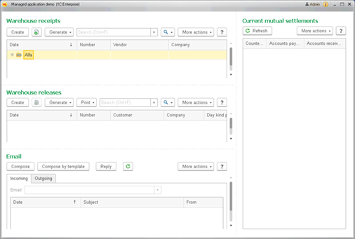
Fig. 73. "Workplace" mode
This mode has the following distinctive features:
-
The system command bar hides the Service and settings menu and all items, except for the client application logo, window header, hyperlink with the username and the About, Collapse, Expand, and Close window buttons.
-
All panels, except for the messages panel and the performance indicators panel, are hidden.
-
Form navigation arrows, the Home page title, the Home button, and the Favorites button are hidden.
-
The context menu accessible by right-clicking the form header is blocked.
-
If the Show title and Show close button form properties are set to False, the entire area with the title containing the form close button is hidden.
-
The following operations and the respective key combinations become unavailable:
-
Panel navigation (Alt + 1, Alt + 2, Alt + 3, Alt+`, F10)
-
Form navigation (Ctrl + Tab, Ctrl + Shift + Tab, Ctrl + F6, Ctrl + Shift + F6)
-
Show/hide all panels (Ctrl + Shift + `)
-
Create new document (Ctrl + N)
-
Open document (Ctrl + O)
-
Save document (Ctrl + S)
-
Print document (Ctrl + P)
-
Print document with current settings (Ctrl + Shift + P)
-
Open calculator (Ctrl + F2)
-
Follow the link (Shift + F11)
-
Get the URL (Ctrl + F11)
-
Add to favorites (Ctrl + D)
-
Open the history panel (Ctrl + Shift + H)
-
Open the favorites panel (Ctrl + Shift + B)
-
Open the search panel (Ctrl + Shift + F)
-
Open the configuration help (F1, Shift + F1, Alt + Shift + F1, Alt + F1, Ctrl + Shift + F1). Note that help in forms is still accessible.
-
Operations with numbers in the clipboard (Shift + Num*, Shift + Num+, Shift + Num–).
-
-
Full-screen workplace. This mode is only used when running Taxi interface. The application starts operating in full-screen workplace mode.
Fig. 74. "Full-screen workplace" mode
This mode (in addition to features of Workplace mode) has the following features:
-
Application windows opens in full-screen mode. Exceptions are the cases of usage of such browser for web client running, which does not support full-screen mode.
-
In the web client, if your browser supports full-screen mode, a confirmation dialog box is displayed before the full-screen mode is enabled.
-
Press Esc to exit the full-screen view while in the web client.
-
In thin and thick client application, the Collapse, Expand, and Close buttons are hidden in the main application window. The Collapse button is hidden in the auxiliary windows.
-
The context menu accessible by right-clicking the system command bar is blocked.
-
Kiosk. This mode is only applicable when running Taxi interface. The application starts operating in kiosk mode.
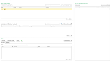
Fig. 75. "Kiosk" mode
This mode has all features of Full-screen workplace mode and the hyperlink with username and the About button are hidden from the system command bar.
- Embedded workplace. This mode can be used, only if a web client is embedded in an external website (see Web client and website integration). When this mode is specified for any other client application, it is ignored and client application main window is opened in the Ordinary mode.
This mode has the following distinctive features:
-
All features of Workplace mode.
-
The system command bar is hidden.
-
РАБОТАЕТ НА 1С (POWERED BY 1C) is displayed in the bottom right corner either in Russian or English. This message cannot be deleted.
You can select the way the application main window is opened in using any of the following three methods (they are listed in the ascending order of priority):
-
In the configuration properties.
-
Using MainWindowMode command available in the command line when a client application is started.
-
Using SetMainWindowMode() 1C:Enterprise language method.
See also:
-
Setting the mode to start client application thin and thick client.
-
Specifying web client run mode.
5.1.2.2. Configuration parameters
Main style. Specifies the style, used for configuration (for details, see Styles and style elements).
Main language. Specifies the main configuration language.
Brief information. Brief configuration description.
Detailed information. Detailed configuration information (multiline text is permitted).
Logo. Logo selection. The logo is selected using the standard image selection window:
Fig. 76. Selecting a picture
Note. Note. The logo image is 64x64 pixels or less. Image type may be any supported by 1C:Enterprise.
Splash. Splash screen selection. The splash screen is selected using the standard image selection window. The image used as splash screen must be 600x255 pixels. Transparency is not supported. Image type may be any supported by 1C:Enterprise.
In some cases, you can completely replace the splash screen displayed at 1C:Enterprise startup. Please address 1C Company to receive such option.
Copyright. Configuration copyright notice.
Vendor information address. Link to the configuration vendor information. It is specified in Copyright property. May be set with both schema prefix (http://) and without it.
Configuration information address. Link to the configuration information. May be set with both schema prefix (http://) and without it. The About window displays Configuration synonym and the following properties: Configuration information address, Copyright, and Configuration vendor information address.
5.1.2.3. Main forms
Default constants form. The default form for entering and editing the configuration constants. This form is selected from common forms in the Common – Common forms configuration branch.
Note. NOTE. This property is only accessible when the configuration editing mode is set to Managed application and ordinary application.
The Main report form, Main report settings form, and Main report option form forms allow you to specify common forms to be used by the reports that do not have the respective forms specified. For example, you can create a common report form containing some features that all application reports must have, such as emailing the generated report. To solve this task, create a common report form, implement the required commands in it, and specify it in the Main report form configuration property. After that all the reports, which do not have the report form specified, will use the created common form.
The Main dynamic list settings form property allows you to specify the common form, using which the dynamic list settings will be edited in the application. If this property is empty, the automatically generated settings form will be used to edit the dynamic list settings.
The Main data history changes form, Main data version history form, and Main data version history differences form properties allow you to specify forms to be used when browsing the data history information. In addition to redefining the data history forms for complete configuration (using the above properties), it is also possible to selectively redefine the data history forms for the selected objects using FormGetProcessing event handler of the selected objects manager module.
The Main form of selection of collaboration system users property allows specifying a form to be used to select users in the message, a conversation, or a video conference of the collaboration system. This form will be used if you click the Show all hyperlink in the list of user selection and the form is not overridden by the form selection handlers (the CollaborationSystemUsersChoiceFormGetProcessing event of the form module or application module).
The Main report appearance template property allows you to specify which appearance template will be used for configuration reports by default (for reports that are built on the data composition system). To change the main report appearance template, use the report appearance manager. To access the manager, use the ReportsAppearance global context property. With the manager, you can set and get the report appearance template for all users or for the current user. When you generate a report, the used template will be determined as follows:
-
If the appearance template is set in the settings of report data composition, this template is used.
-
If the template is not set in the settings of report data composition:
-
If the template is set using the ReportsAppearance.SetUserAppearanceTemplate() method, this appearance template will be used.
-
If the template is set using the ReportsAppearance.SetCommonAppearanceTemplate() method, this appearance template will be used.
-
If the appearance template is set in the Main report appearance template configuration property, this template will be used.
-
Otherwise, the Main report appearance template integrated into the platform is used.
-
See also:
-
Redefining standard object forms (see Redefining the form being opened).
-
Collaboration system user choice form determination (see Selecting collaboration system users).
5.1.3. Specifying development properties
This properties category specifies the configuration vendor and version data.
Update directory address. Contains a resource address to be used to update the application.
5.1.4. Properties related to development for mobile devices
Intended use. Refers to application intended use (Platform application or Mobile platform application). The property is available only if the Default run mode property is set to Managed application. Depending on the selected use purpose, the capabilities of Designer change:
-
PC application. Development of an application that will run in thin, thick, web, and mobile client applications. The developed application will not run on a mobile platform.
-
Mobile platform application. Development of an application that will run on mobile devices. In this case, the developer has access to a limited set of applied objects (for limitation list, see Mobile 1C:Enterprise version specifics).
-
When both of the checkboxes are selected (Platform application and Mobile platform application), you can develop applications containing all 1C-supplied objects. However, the developed application may not run properly on a mobile version. The reason for this may be, for example, using configuration objects that are not supported by the mobile platform.
You need to consider the following:
-
If usage purposes do not have PC application, then:
-
You cannot change the default run mode.
-
You cannot change the mode of the main client application window.
-
You cannot select a preview option in the form editor.
-
Properties that are not used on the mobile platform are unavailable in the property palette (see Property palette) for configuration objects.
-
Only types available on the mobile platform can be used as attribute types.
-
-
If configuration purposes do not have Mobile platform application, then:
-
Module verification uses the setting for the Mobile platform application mode. This mode is offered by default for modification when editing parameters.
-
Configuration verification uses separately stored settings of checks performed.
-
Syntax Assistant uses the separately stored settings of the imposed filters.
-
Used functionality of the mobile application. Describes the features of 1C:Enterprise mobile platform to be used by the mobile application. The developer determines the functionality list based on the task to be completed. Required functionalities must be selected manually. They will not be automatically selected based on the application code analysis.
The selected functionality checkbox controls several mobile application features:
-
The functionality determines which permission the builder will enable for the built mobile application.
-
The message text upon permission request will be shown to the user at the moment the application requests the required permission.
-
If a certain functionality is disabled, in some cases the mobile application builder will remove the associated module from the mobile application being built. This will reduce the application size. Besides, an attempt to call any method from a disabled module will result in a runtime error.
For more information on 1C:Enterprise language functionality operations, see Used functionalities.
The mobile version of 1C:Enterprise for developers always has all the required permissions, regardless of the methods and objects used by the application. Despite this, the mobile version for developers emulates behavior of the built application. This way, the developer will be able to understand how the built application will operate without actually building it.
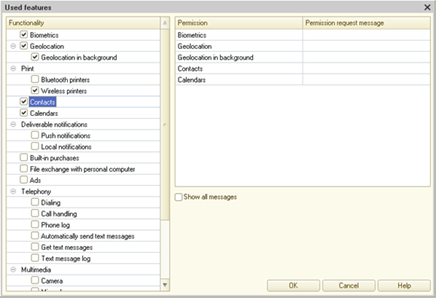
Fig. 77. Mobile application functionality editor
When the mobile application tries to use a feature that requires permission to perform the action from the user, the mobile operating system will show the dialog box with the permission request to the user. The text describing what the mobile application requires permission for will be shown in this dialog. This permission text may be specified by the configuration developer. To do it, use the Permission request message column in the Used functionality dialog box. If the configuration supports several languages, the message text can be standardized for each language. In the right field (where you edit the permission texts), add the functionalities selected in the left field. If you disable a functionality, its permission request text will not be deleted.
If you select a permission in the list of permissions, in the list of functionalities, the functionalities for which the permission request text will be used in the built mobile application will be highlighted in bold.
Use the Show all messages checkbox to enable or disable the mode that displays all functionalities and permission requests in the right field, not only the selected ones.
Mobile client signature. Allows you to manage the digital signature of the application used in the mobile client (for more information on digital signature, see Digital signature and configuration digest). Click Open to open the dialog box to perform several operations:
-
Check the correspondence between the digital signature and the configuration status.
-
Create a private digital signature key for this configuration (and save it to the specified file).
-
Generate a digital signature for the configuration.
-
Clear the digital signature.
Information on the status of the digital signature is shown at the top of the dialog box.
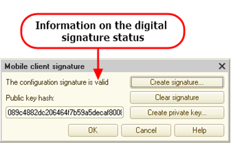
Fig. 78. Mobile client signature
If the configuration is not signed, the dialog box displays message Configuration is not signed. If the current configuration status does not match the digital signature, the label in the dialog box changes to The configuration signature has expired. In both cases, you must create or update the digital signature using the Create signature button. When you click this button, the system requests the path to the file with the digital signature private key. After the generation of the digital signature, the public key hash value is generated in the Public key hash field in the Base64 format for store in the MobilePublicKey parameter of the file with the common infobase list (.v8i). If the configuration is not planned for use with a mobile client, you do not need to generate the digital signature.
Standalone configuration content. Defines the standalone configuration content of the mobile client in the standalone mode.
Limiting roles of the offline mobile application. Defines roles restricting features available to a user operating on a mobile device. This set of roles is used as follows:
-
All roles assigned to a user are combined "by OR".
-
All roles specified in this property are combined "by OR".
-
The results obtained for a user and this property are combined "by AND".
Therefore, roles defined in this property are intended to restrict access rights available to a user operating a mobile device. For instance, if you need to restrict creation of Goods catalog elements, do the following:
-
Create a role named RestrictedOfflineApplication (by way of example only).
-
Grant all rights to a user with this role assigned. As such, the rights available to other roles will be reserved.
-
Disable creation of new elements for Goods catalog. Thus, a user is no more able to create further goods on their mobile device.
-
Select in a list of roles of Limiting roles of the offline mobile application property RestrictedOfflineApplication only.
Note that you can use RestrictedOfflineApplication to disable all unwanted access rights on a mobile device without modifying main application roles.
5.1.5. Specifying help properties
Include in help contents. If the property is specified, the help contents will be included in the general configuration description.
Help information. The Open link opens the configuration description editing window.
5.1.6. Specifying compatibility properties
Data lock control mode. Option of data lock management in transaction (see Data operations).
Binary data storage mode determines whether the binary data storage can be used. The property is available if 1C:Enterprise version 8.3.22 or later is used, and the Compatibility mode property is set to values from Version 8.3.10 to Version 8.3.21 (inclusive). When you change the property value, the behavior will be as follows:
-
The value is set to Use: the binary data storage is available.
-
The value is set to Do not use: the binary data storage is unavailable.
If the Compatibility mode property is set to Version 8.3.22 or later, the Binary data storage mode property becomes unavailable, and the binary data storage is always available.
Objects automatic numbering mode. Determines, whether automatically retrieved object numbers are reused, if these have not been recorded to the database.
AutoFree value of this property is used to ensure the numbering mode similar to 1C:Enterprise 8.0. Numbers and codes retrieved automatically will be further used, if the object, which these have been retrieved for, has not been recorded.
NotAutoFree value of this property is used to select the numbering mode, when the numbers for the objects requiring continuous numbering are be assigned the numbers when being recorded and when the form is opened.
If the object (document, catalogue item, chart of characteristic types, business process or task) number has been allocated in transaction, it will be reused even in case if the NotAutoFree automatic numbering mode is enabled, including if the object has not been recorded during transaction.
The NotAutoFree automatic numbering mode affects only numbers assigned outside the transaction. If the number is assigned outside the transaction and the code is not used (the object was not recorded), the number is not used in the NotAutoFree mode again, but it will be reused in the AutoFree mode.
Modality usage mode. Specifies if it is possible to use the methods, causing the modal windows to open, in the application. If the property is set to Use, it is possible to use modal windows without any restrictions. If the property is set to Do not use, it is not possible to use the modal windows in this application. The error is returned when attempting to use the methods (including during syntax check in the 1C:Enterprise language). Use blocking windows instead of the modal windows (see Different approaches to modality). If the property has Use with warning value, errors will not be returned when using modal windows, but a message will be output to message window, that modal windows cannot be used in this mode. When using this mode modal windows must be replaced with blocking.
Stating with 1C:Enterprise version 8.3.5 behavior of thin and thick client applications slightly changes. The behavior described above (for thick and thin client applications) will be observed only if /EnableCheckModal 1C:Enterprise startup command line parameter is used. If this parameter is not specified, the modal methods remain operable regardless of the Modality usage mode configuration property. In particular, such behavior allows using external data processors, written without considering Modality usage mode property, in configurations, written with a glance to setting this property to Do not use.
If 1C:Enterprise is started from Designer (see Starting 1C:Enterprise), the /EnableCheckModal startup command line parameter is set forcibly without an option to configure such behavior.
Synchronous platform extension and add-ins call use mode. Property controls the feature to use the synchronous calls of file system extensions, cryptography and add-ins. If the property is set to Use, the synchronous methods for extensions and add-ins will be available on client side. If the property is set to Do not use, synchronous methods become unavailable in Syntax Assistant, context help when editing modules and the extended configuration check reports errors if client-side synchronous calls are detected. It is recommended to use asynchronous methods in this case. Synchronous methods that perform operations with extensions and add-ins generate exceptions in 1C:Enterprise mode. Use with warnings mode is an intermediate option, where the use of synchronous methods is allowed, however, each such method generates a warning both in 1C:Enterprise mode and during the extended configuration check. Thick client generates actual value of this configuration property. When using thick client all the synchronous methods are executed without exceptions and warnings.
When using web client, running in Google Chrome or Mozilla Firefox, the following behavior is implemented:
-
The property is set to Do not use, the file system and cryptography extensions, which are represented by synchronous methods, do not load. The extensions, represented by the asynchronous modes, are used.
-
In other cases, when connecting the file system and cryptography extensions, loading of extensions representing the synchronous methods is attempted. If the attempt is successful, the possibility to use both synchronous and asynchronous file system and cryptography methods is provided. If the "synchronous" file system and cryptography extensions are not operable, the extensions that provide asynchronous methods will be used.
Note that the support for synchronous methods in Google Chrome became disabled by default in version 42 (April 2015) and was completely removed in version 45 (September 2015). Mozilla Firefox does not support synchronous calls in web browser starting from version 43 (December 2015).
At the same time the above behavior will be observed if the /EnableCheckExtensionsAndAddInsSyncCalls client application startup command line parameter is used.
If 1C:Enterprise is started from Designer (see Starting 1C:Enterprise), the /EnableCheckExtensionsAndAddInsSyncCalls client application startup command line parameter is set forcibly without an option to configure such behavior. The exception from above is starting the thick client, for which this command line parameter is not set when starting from Designer.
Interface compatibility mode. This property manages the client application interface mode:
-
Version 8.2. Client application runs in version 8.2 interface. Switching to Taxi interface is not possible. This mode is not supported when using the web client.
-
Version 8.2. Allow Taxi. Version 8.2 interface is used by default.It is possible to switch toTaxi interface using parameters dialog box, ClientSettings object or command line. This mode is not supported when using the web client.
-
Taxi. Allow Version 8.2. Taxi interface is used by default. It is possible to switch to version 8.2 interface using parameters dialog box ,ClientSettings object or command line. This mode is not supported when using the web client.
-
Taxi. Client application uses Taxi interface. Switching to 8.2 interface mode is not possible.
When using version 8.2 interface it is possible to switch between the interface in separate windows and interface in tabs.
Only Taxi interface is supported in the wen-client. If another interface compatibility mode is set in the configuration settings with the help of the embedded language or startup command line command, these settings are ignored and Taxi interface will be used.
If the Compatibility mode property is set to a value greater than Version 8.3.2 (Do not use, Version 8.3.3 and later), and the Interface compatibility mode property is set to Version 8.2 or Version 8.2. Allow Taxi, then the interface in tabs will be automatically set for new application users.
PictureLib.Help image is displayed in many ways, if Interface compatibility mode property is set to Taxi or Taxi. Allow Version 8.2 and in other cases.
You can edit the Table space usage mode property only if the configuration compatibility mode is 8.3.22 or earlier. If the configuration compatibility mode is later than Version 8.3.22, you cannot manage the Table space usage mode property but you can always use table spaces.
If the Table space usage mode property is enabled, you can use the infobase only in 1C:Enterprise 8.3.23 or in later versions. If you want to use an infobase of version 8.3.22 or earlier, move all database objects to the default namespace and disable table spaces.
Compatibility mode. The property controls the behavior of features, which has been changed in the new system version in comparison to the previous versions. This property can take the following values: Version 8.3.26 – Version 8.3.1, Version 8.2.16 Version 8.2.13 Version 8.1, and Do not use. For details on the system operation in a particular version compatibility mode, see Compatibility mode specifics.
Using configuration with unknown compatibility mode is not supported. Unknown compatibility modes are the modes, that do not match the functions, implemented in the following 1C:Enterprise versions. For example, if the compatibility mode is set to Do not use in version 8.3.1, it will be considered unknown when opening the configuration in version 8.2.16. At the same time, if the compatibility mode is set to Version 8.2.16 in version 8.3.1, then when opening the configuration in version 8.2.16, it will be displayed as Do not use. If the specific version does not introduce a new compatibility mode, the effect of the Do not use mode will be similar to the previous version. If attempting to run or load a configuration with the unknown compatibility mode, an error will be displayed indicating the required version. Importing1cv8.dt files generated in version 8.3.1 and later into 1C:Enterprise versions prior to 8.3.1 is not allowed. The only exception is when the Compatibility mode configuration property is set to Version 8.2.16 in 1C:Enterprise 8.3.1 and later.
When converting configurations of the 1C:Enterprise 8.1 versions (and earlier), the property assumes the Version 8.1 value. In general case, it may be said that when a configuration is opened with a later version of 1C:Enterprise, the Compatibility mode property will be set to the compatibility with the previous version if such mode is introduced in the new version.
If it is necessary to ensure the operation of the application in several 1C:Enterprise versions at once (including for the ones with a compatibility mode), then it is recommended to first receive the current version of the platform in areas of different code calls and then compare it with the compatibility mode (if necessary). However, it is not recommended to check the compatibility mode for the DontUse value.
The mobile platform compatibility mode has several differences:
-
Mobile platform compatibility mode is not managed by configuration properties (including the Compatibility mode property). However, this property exists "inside" the mobile application.
-
The setting of the compatibility mode value is performed when creating the infobase. The compatibility mode value will correspond to the version of the mobile platform that was used to create the infobase.
-
Updating the mobile platform version does not update the compatibility mode value.
-
When updating the mobile application infobase configuration, the compatibility mode is set to a value equal to the mobile platform version that was used to update the configuration.
-
Accordingly, all the methods of 1C:Enterprise language the behavior of which considers the compatibility mode will consider the compatibility mode generated as per the above rules.
5.2. Managed application module
For more information on the managed application module, seeManaged application module.
The managed application module, being part of the configuration, is saved only as part of the configuration. Using the File – Save item will result in the saving of the changes made to the entire configuration.
5.3. External connection module
For more information on the external connection module, seeExternal connection module.
5.4. Session module
For more information on the session module, seeSession module.
5.5. "Common" configuration branch
This section describes some configuration objects that are located in the Common branch of the configuration tree. These objects do not describe the data structure and their processing functions. These are intended for setting user data processing rules, descriptions of auxiliary objects used to generate various forms in the data exchange engine, and also contain common modules and print form templates available from any configuration module.
5.5.1. Subsystems
Subsystems generate a global configuration command interface. To find out how to use subsystems to generate the command interface, see Subsystems.
Note. Note. Setting the subsystem name Desktop is not recommended.
Subsystems can be nested. There are no restrictions on the number of subsystems and their nesting. Each subsystem contains configuration objects for which the subsystem acts as a logical grouping. For example, the Finances subsystem contains all configuration objects related to financial accounting.
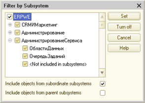
Fig. 79. Subsystems Editing window
The Subsystem with one command property allows you to specify the subsystem that will execute the standard command of the object included in the subsystem. It makes sense to select this checkbox only for top-level subsystems. This is due to the fact that nested subsystems are always displayed in the functions menu of the current section and are not displayed in the sections panel. In the Taxi interface of the client application, when you activate a section where the Subsystem with one command checkbox is selected, the number of commands in this section is checked considering subsections and command accessibility for the current user. If only one command is available in the section, it is executed. The current section does not change. Similar behavior is observed when you follow the URL to such section. If the subsystem contains more than one displayed command, the standard functions panel of the current section will be opened.
When you update the infobase configuration, it is checked whether the subsystem contains more than one command (not considering access rights, and so on). If the subsystem contains more than one command, Designer displays a warning.
The Image property allows you to specify an image that will be displayed in the sections panel (for top-level subsystems). When specifying the images of different size, the height of the section panel will be calculated depending on the interface compatibility mode:
-
Version 8.2:
-
The section panel height is calculated based on the fact that the vertical size of all images is 48 pixels.
-
Smaller images are proportionally decreased so that the vertical size is 48 pixels.
-
-
Taxi:
-
If there is at least one section image where the vertical size is more than 48 pixels, all such images will be proportionally decreased so that the vertical size is 48 pixels.
-
If all the section panel images have a vertical size of less than 48 pixels, then the height of the section panel is calculated based on the maximum vertical size of the images, while the smaller images are centered in the areas reserved for the images.
-
If the Include in the help content property is set, then the help content will include a branch that displays help on the subsystem and all the objects included in it. If the property is cleared, then such a branch (describing the subsystem and objects included in it) will not be included in the help content, but the help on the objects included in the subsystem will be available directly in the forms of the objects themselves.
You can add a metadata object to a specific subsystem (or subsystems) on the Components tab of the subsystem editor.
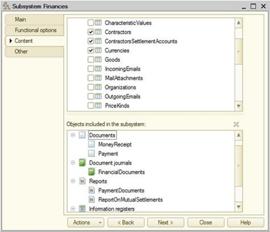
Fig. 80. Subsystem components
All configuration objects that can be assigned to different subsystems are listed at the top of the window. Select an object (for example, Payment in fig. 80) to include it in the subsystem. After that, it will appear at the bottom of the window. All objects included in the edited subsystem are displayed at the bottom of the window. Whether configuration objects belong to a certain subsystem defines the user interface.
To view configuration objects related to a specific set of subsystems, it is possible to configure the objects selection filter in the Configuration window. Select the Actions – By Subsystems item of the Configuration window and specify the required set of subsystems, as well as set additional selection criteria Include objects of subordinate subsystems and Include objects of parent subsystems.
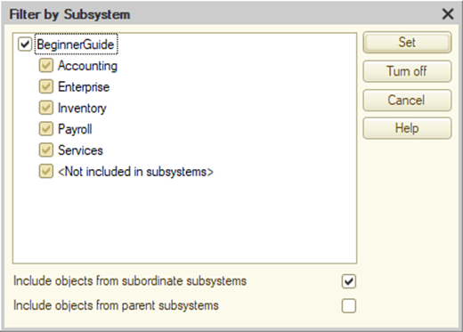
Fig. 81. Selection by subsystems
In the list of subsystems, there is a special item <Not included in subsystems>, using which it is possible to select only the objects that do not belong to any subsystem.
To quickly select objects included in a specific subsystem, you can use the Subsystem objects context menu command. Executing this command is similar to executing the Action – By subsystems command, with specifying only one subsystem in the opened dialog box. When selecting by subsystem, the key branches of the configuration object tree, which do not contain selected objects, are not shown.
The Move subsystem context menu command allows changing the subordination of the subsystem in the subsystem hierarchy.
The Metadata.Subsystems global context property provides access to the entire hierarchy of subsystems using 1C:Enterprise language. The Subsystem metadata object describes each subsystem. This object has an application programming interface that allows you to access:
-
All subordinate subsystems. Use the Subsystems property for that. To access a parent subsystem, use the Parent() method.
-
List of objects included in the current subsystem. Use the Components property for that. The collection will contain metadata objects included in the subsystem.
5.5.2. Common modules
Objects located in the Common modules configuration tree branch can contain texts of functions and procedures that you can call from any other configuration module.
Note. NOTE. A common module may only contain the definitions of procedures and functions.
Procedures and functions of the common module, for which the Export keyword is shown in the headers, are global context components. For more information on how to write procedures in a common module, see "Format of module source text" and "Operators" in the 1C:Enterprise language help.
To edit the common module, click Open in the Common modules type object property palette in the Module property of the Configuration window. The text of the common module will be displayed for editing in the 1C:Enterprise text editor in the program module text editing mode.
The common module, being part of the configuration, is saved only as part of the configuration.
The Global property defines whether exported methods of the common module are a part of the global context.
When the Global property is set to True, exported methods of the common module are available as global context methods.
When the Global property is set to False, a property is created in the global context with the name matching the name of the common module in the metadata. This property is read only. The value of this property is a CommonModule object. Exported methods of this common module are available through this object. Thus, non-global common module method calls have the following format: XXXXX.YYYYY, where XXXXX is the name of the common module context matching property, and YYYYY is the name of the exported method of the common module.
Example:
OperationsWithShopEquipment.ConnectBarCodeScanner();5.5.2.1. Various contexts and common modules
Using the common modules properties and preprocessor commands it is possible to arrange the execution of various methods of common modules in the desired context.
Each property of a common module is responsible for the possibility to compile (and execute) a common module in a particular context.
The following properties, responsible for the context, are available, where the methods of the common module are available:
-
Client (ordinary application). Common module methods will be available for the thick client in the ordinary application mode.
-
Client (managed application). Common module methods will be available to the thin client, web client, and the thick client in the managed application mode.
-
Server. Common module methods will be available on server.
-
External connection. Common module methods will be available in the external connection.
If several properties are set at the same time, this means that the common module methods will be available in several contexts.
If the Server property and another property are set for common module, this means that the common module will be available simultaneously on the server and in the selected client. It should be understood that these in fact will be several variants of the compiled code (based on the number of selected clients and for the server itself).
However, if a method located in such a common module is called from the client side, then a client copy of the common module will be used, and if it is called from the server, the copy from the server will be applied. In this case, using preprocessor commands (see Preprocessor commands), you can "isolate" the server from the code that cannot be executed on it.
Consider an example. In the general module (which can be executed on the thin client and on the server) there is a method that has slightly different behavior on the thin client side and on the server side. Let us see how to do this:
Procedure CommonModuleMethod() Export
// Place various important code here
#If ThinClient Then
// Show a warning
ShowUserNotification ("On client");
#EndIf
EndProcedureThe server side code will be as follows:
Procedure CommonModuleMethod() Export
// Place various important code here
EndProcedureThe thin client side code will be as follows:
Procedure CommonModuleMethod() Export
// Place various important code here
// Show a warning
ShowUserNotification ("On client");
EndProcedureThere are several ways to pass control from client to server:
-
Call the server common module method.
-
Call the method that is preceded by the &AtServer, &AtServerNoContext compilation directives in the form or command module (see Form module).
At the same time, it is impossible to call the methods of client common modules (which do not have the Server property set) and client methods of the form module or the command module from server procedures. The control will return to the client after the most external call of the server method is completed.
The exceptions are the methods of the form module and the command module, which are preceded by the &AtClientAtServer and &AtClientAtServerNoContext compilation directives (see Form module).
The following points must also be mentioned:
-
If a common module is available for more than one client, then when writing code, consider the maximum restrictions that can be imposed by clients, or use preprocessor commands to "isolate" client-specific code.
-
The preprocessor commands also make sense when one common module has several execution contexts, for example, an external connection and a thin client or (which is much more common) any client and a server. In this case, the preprocessor commands will wrap interactive code that cannot be used on the server, but is possible on the client (see the example above).
The Server call property is intended to manage the possibility to call the exported methods of the server common module from the client code. If the property is set, the exported methods of the server common module are available for calling from the client. If the property is not set, such exported methods can be called only from server methods (both methods of server common modules and server form module methods and command modules).
Note. TIP. We recommend that you set the Server call property to False in cases where the server common module contains methods that are undesirable to call from the client (for example, for security reasons).
Note. NOTE. If the Client (ordinary application), Client (managed application), External connection properties are set at the same time, the Server call property is automatically reset. If the Server Call property is set, the Client (ordinary application), Client (managed application) and External connection properties are automatically reset if these properties are set at the same time.
The Privileged property is designed to disable access control when executing common module methods.
Note. NOTE. If the Privileged property is set, the common module is automatically assigned the Server property and all the other properties (Client (ordinary application), Client (managed application) and External connection) are reset. Privileged common module may only be executed on the server.
For more information about privileged mode, see Privileged operation mode.
5.5.2.2. Return value reuse
If the common module is not global, the Return value reuse property becomes available. This property can have the following values:
-
Do not use. Reusing return values for functions of this common module is not allowed.
-
During call and During session. Method to determine return value reuse is used for the common module. The essence of this method is that during the execution of the code, the 1:C Enterprise caches the parameters and the result of the functions after the first function call. When the function is called again with the same parameters, the cached value is returned (from the first call) without executing the function itself. If the function execution changes its parameters, the return values are not reused.
Storing the function result has some specificities:
-
When a function is executed on the server and is called from the server code, the parameter values and the function result are cached for the current session on the server.
-
When a function is executed on the thick or thin client, the parameter values and the function results are cached on the client.
-
When a function is executed on the server but called from the client code, the parameter values and function result are cached both on the client and on the server (for the current session).
Cached values are deleted:
-
If the common module property is set to During call:
-
On the server. When the server returns the control.
-
On the client. When the top-level 1C:Enterprise language procedure or function (called from the interface, not from another 1C:Enterprise language procedure or function) is completed.
-
-
If the common module property is set to During session:
-
On the server. When closing the session.
-
On the client. When closing the client application.
-
The cached values will be deleted:
-
On the server, in the thick client, in the external connection, in the thin client, and in the web client with normal connection speed. Twenty minutes after calculating the cached value or six minutes after the last use.
-
In thin client and in web client with low connection speed. Twenty minutes after calculating the cached value.
-
When there is a shortage of memory in the server working process.
-
When a working process is restarted.
-
When the client switches to another working process.
After the values are deleted, an exported function call is performed in the same way as for the first call.
This common module property does not affect the execution of procedures. The procedures are always executed.
If the common module is set to reuse the return values, the types of parameters of the exported function are subject to a number of restrictions. Parameters can only be of the following types:
-
Primitive types (Undefined, NULL, Boolean, Number, String, Data).
-
Any database object references.
-
Structures with values of the above type properties. In this case, the identity of the parameters is controlled "by content" of the structures.
If the exported function returns any object, the reference to the object stored in the cache is actually returned. If, after receiving this reference, there is a change in the object condition, a subsequent call of the same function will result in returning the reference to the object that has already been changed without actually executing the function. This behavior will be observed until the cached value is deleted (for any reason). In other words, changing the object state received when calling from the common module with the return value reuse is not a reason to call the function. Note that the cache of the returned objects is insensitive to the privileged mode state at the time when the function with return value reuse is called. This feature may cause the following behavior:
-
The function with the return value reuse was called (for the first time) with the enabled privileged mode.
-
When executing the function, an object was received that could not be retrieved with the privileged mode disabled.
-
Subsequent function calls were performed without setting the privileged mode on.
-
However, until the cache of the returned objects is cleared or the actual call is repeated, the function will return a formally unavailable object.
-
The reverse behavior is also applicable when the first call is performed without setting the privileged mode, and in the privileged mode the object that could have been retrieved in the privileged mode is not returned.
If the Return value reuse common module property is set to During session, values returned by module functions cannot use values of the TempTablesManager, Query types and applied objects (for example, DataProcessorObject or DocumentObject) both directly and within any collections. Exceptions are reference type data (DocumentRef, CatalogRef, and so on).
If a common module function that reuses return values is called from the same common module (for example, with theCommonModule name), you need to consider one moment. If the function is called by the MyFunction() name, the function will be executed each time it is called. To use the saved values, call the function by the full name: CommonModule.MyFunction().
The RefreshReusableValues() global context method deleted all the reusable values, both on the server and on the client, regardless of where the method is called from. After executing RefreshReusableValues() method, the first function call will be executed completely.
5.5.3. Session parameters
Session parameters are mainly intended for using parameter values in queries and data access restriction conditions for the current session.
Using the session parameters reduces data access time by excluding the related tables.
Session parameters are configured in the property palette.
For each session parameter, two access rights are defined: Get and Set (see the section below for more details). If the Setting right is removed, then the initialization of this session parameter is only possible in the common module with the Privileged property set or in the session module.
Session parameters can be initialized in the session module, in the SessionParametersSetting() event handler (see Session module).
Prior to initialization, the session parameter value is undefined. When attempting to read such parameter, the SessionParametersSetting() event handler is called first. If the parameter remains undefined after the call, an exception is thrown.
The managed application module (external connection module) session parameters and global variables application areas must be distinguished. The main differences of session parameters are:
-
Session parameters are metadata objects, which allows 1C:Enterprise to exercise enhanced control over their use.
-
Session parameters have a type. The set of session parameter types is limited. Their important common feature is the impossibility of changing the internal condition of the objects of these types.
-
To set or retrieve the value of a session parameter, the current user must be granted the appropriate rights.
-
In the client/server mode of 1C:Enterprise, the values of the session parameters are stored on the server and are accessible both from the server and from the client.
-
Session settings are available from both 1C:Enterprise language, for example:
SessionParameters.CurrentUser = UserName()And from the data access restrictions, for example:
Document.Report.User = &CurrentUserIn the latter case, the current user requires no respective right to retrieve the value of the session parameter.
Note. Note 1. If the session parameter is set to one of the following types:FixedArray, FixedCollection, or FixedStructure, the Undefined value may be the value of the collection item.
Note. Note 2. The amount of data transferred between the client and the server to set a single session parameter must not exceed 4 GB (in serialized form).
5.5.4. Roles and access rights
5.5.4.1. General information
Each user must have free access to common information, such as common catalogs, constants or enumerations.
On the other hand, it is necessary that each user dealt only with the information that they require for work, and could in no way by their careless actions affect the operations of other users or the performance of 1C:Enterprise as a whole.
The 1C:Enterprise Designer provides developers with advanced administration tools designed to solve these problems.
First of all, during the process of configuration generation, the necessary number of typical roles is created, which describe the rights of various categories of users to access the information processed by the 1C:Enterprise. Roles may be set in a fairly wide range: from the possibility of only viewing a limited number of document types to the full set of rights to enter, view, adjust and delete any types of data.
1C:Enterprise has two types of rights: basic and interactive. Basic rights are always checked no matter how infobase objects are accessed. Interactive rights are checked when executing interactive operations, such as viewing and editing in the form and other. For available access rights, see Access rights description or the description of the AccessRight() global context method in Syntax Assistant.
If the View right is set (permitted) for the object, which data is represented in the form, but the Edit right is not set, this attribute (the control, associated with this object, displays the attribute value) will be displayed in the form, but editing the value will not be available. If the View access right is cleared when attempting to open a form, the user will see the Access violation warning, and the form will not be opened.
In the list of rights when editing a role, the attention must be paid to the internal rights hierarchy. The hierarchy is represented in the form of "seniority" of the rights. When removing a "senior" right, other rights ("junior rights") related to the "senior" right are removed, and vice versa, when setting "junior" rights, removed "senior" rights are set. So, when removing the View right, the Edit right is also removed. It is quite logical as it makes no sense to provide the right to edit if it is impossible to display the control related to the data.
In general case, the rights may be set for:
-
Entire configuration
-
Objects
-
Object attributes
-
Tables
-
Table attributes
-
Standard attributes
When you create a new role, the following access rights are set for the root configuration object: ThinClient, WebClient, SaveUserData, and Output.
5.5.4.2. Privileged operation mode
On the 1C:Enterprise server, code fragments can be executed both in normal and in privileged mode. In privileged mode, access control at the record level is not performed, rights are not controlled, and any operations are allowed, which speeds up the execution of modules.
To control the privileged mode, use the SetPrivilegedMode() global context method that allows you to enable or disable the privileged mode.
Note. IMPORTANT. In the client/server mode, the method call does not affect the usage of the client.
Privileged mode is disabled by default.
The number of privileged mode activations must match the number of shutdowns. However, if a privileged mode (once or more) was enabled within the procedure or function, but was not disabled, the it will be automatically shut down as many times as there were incomplete activations in the procedure or function
If the procedure or function contains more SetPrivilegedMode(False) method calls, than SetPrivilegedMode(True) method calls, the exception will be thrown.
PrivilegedMode() functions returns True value, if the privileged mode is enabled, and False value, if it is completely disabled. It does not analyze the number of privileged mode settings in a particular function.
The programmatical setting of the privileged mode may be required in case of massive operations with the infobase data, and when it does not make sense to check the data access rights. For example, there is a user who is entrusted to perform the recalculation of the prices for goods. Then, in data processor, for example, which performs this operation, it is possible to check the current user's right to perform this data processing, and then enable privileged mode and perform all the necessary operations with the database. At the same time, the user may not have rights to read prices. But since this data processor does not output the prices themselves to the user, but only recalculates them, the assigned access restriction tasks will also be solved.
It is also possible to start a privileged session. This is a session where privileged mode is set from the very beginning of the 1C:Enterprise operation. In this case during the operation thePrivilegedMode() method will always return True, and the possibility to disable the privileged mode is not supported. Only a user with administrative rights (Administration right) can start a privileged session. Session start is possible using the UsePrivilegedMode client application startup command line option or prmod infobase connection string parameter.
5.5.4.3. Safe mode
If it is necessary to use "unreliable" program code on the server: external data processor or program code entered by the user to use in the Execute() and Eval() methods, you can use safe mode.
In safe mode:
-
Privileged mode is cancelled.
-
Switching to privileged mode is ignored.
-
Operations that lead to using tools external to the 1C:Enterprise platform are prohibited (including non-blocking analogs of these methods):
-
COM tools:
-
COMObject()
-
GetCOMObject()
-
HTMLDocumentShell.GetCOMObject()
-
-
Add-in import:
-
LoadAddIn()
-
AttachAddIn()
-
-
File system access:
-
ValueToFile()
-
FileCopy()
-
MergeFiles()
-
MoveFile()
-
SplitFile()
-
CreateDirectory()
-
DeleteFiles()
-
New File
-
New xBase
-
HTMLWriter.OpenFile()
-
HTMLReader.OpenFile()
-
XMLReader.OpenFile()
-
XMLWriter.OpenFile()
-
FastInfosetReader.OpenFile()
-
FastInfosetWriter.OpenFile()
-
XMLCanonicalizingWriter.OpenFile()
-
XSLTransform.LoadFromFile()
-
ZipFileWriter.Open()
-
ArchiveFileWriter.Open()
-
ZipFileReader.Open()
-
ArchiveFileReader.Open()
-
New TextReader() if the first parameter is a string.
-
TextReader.Open() if the first parameter is a string.
-
New TextWriter() if the first parameter is a string.
-
TextWriter.Open() if the first parameter is a string.
-
New TextExtraction()
-
Change the TextExtraction.FileName property
-
TextExtraction.Write()
-
New Picture() if the first parameter is a string.
-
Image.Write()
-
New BinaryData()
-
BinaryData.Write()
-
New DataWriter() if the first parameter is a string.
-
New DataReader() if the first parameter is a string.
-
All the FileStreamsManager object methods
-
New FileStream()
-
FormattedDocument.Write()
-
GeographicalSchema.Read()
-
GeographicalSchema.Write()
-
GeographicalSchema.Print()
-
SpreadsheetDocument.Read()
-
SpreadsheetDocument.Write()
-
SpreadsheetDocument.Print()
-
GraphicalSchema.Read()
-
GraphicalSchema.Write()
-
GraphicalSchema.Print()
-
TextDocument.Read()
-
TextDocument.Write()
-
-
Internet access:
-
New InternetConnection
-
New InternetMail
-
New InternetProxy
-
New HTTPConnection
-
New FTPConnection
-
-
Note. IMPORTANT. When prohibited operations are performed in safe mode, an exception is thrown.
Note. Note. External reports and data processors that are opened using the File > Open menu, run in safe mode if the user does not have administrative access rights.
The number of safe mode activations must match the number of shutdowns. However, if a safe mode (once or more) was enabled within the procedure or function, but was not disabled, the it will be automatically shut down as many times as there were incomplete activations in the procedure or function.
If the procedure or function contains more SetSafeMode(False) method calls, than SetSafeMode(True) method calls, the exception will be thrown.
Programmatic setting of safe mode may be required when the configuration developer assumes the use of third-party (with respect to the configuration) program code, the reliability of which cannot be guaranteed by the developer. An example of such code is the execution of the Run() and Calculate() methods in cases where the executable code is obtained from the outside. In this case, good practice will be to set a safe mode before executing these methods:
// Generates a program code to be executed
// It is possible that the code is loaded from
external sources
// or is entered manually
ExecutableCode = GetExecutableCodeFromOutsideWorld();
// Enable safe mode
SetSafeMode(True);
// Run the potentially dangerous code
Run(ExecutableCode);
// Disable safe mode
SetSafeMode(False);In some cases, the safe mode settings may conflict with the privileged mode settings (see Privileged operation mode). An example of such conflict is the posting of the document for which the Privileged mode during posting property is set, from the code in the 1C:Enterprise language, which is executed in safe mode. In this case, the privileged mode is disabled, and attempts to enable it are ignored. As a result, the code in 1C:Enterprise language that expects the enabled privileged mode "finds out" that it is disabled. It leads to errors with unclear reasons. To prevent such situation, 1C:Enterprise automatically disables the safe mode for event handlers that are available in the object module or the manager module. In this case, the executable code in 1C:Enterprise language cannot be located in the configuration extension (see Configuration extension). Such handlers are marked in a special way in the Syntax Assistant (for details, see Specific features of using objects, their properties and methods).
Various actions can be performed in event handlers of configuration objects that must be unavailable when in unsafe code. For example, you cannot edit a catalog from an external data processor running in safe mode. However, when opening handlers, the 1C:Enterprise platform forcibly disables safe mode. To solve this issue, we need to find out from which code the operations with the object were initiated and then locally enable or disable safe mode. To solve the first task, use the GetSafeModeDisabled() method, which returns True if safe mode is disabled automatically or using a special method. A special method is a solution to the second issue and allows you to control safe mode inside the object event handler. The method is called SetSafeModeDisabled().
Let's consider an example. If the Goods catalog cannot be changed from the code that runs with safe mode enabled, the possible implementation of this lock may look as follows:
// somewhere in the code on the server
SetSafeMode(True);
Object = Cat.FindByCode(0).GetObject();
Object.Description = "Invalid change";
Object.Write();
SetSafeMode(False);
// event handler of the Goods catalog object module
Procedure OnWrite(Cancel)
If GetSafeModeDisabled() Then
SetSafeModeDisabled(False);
EndIf;
If SafeMode() Then
Cancel = True;
Raise("Cannot
change the catalog from external code");
EndIf;
EndProcedureIf you need to return safe mode in the event handler, the handler will look as follows:
Procedure OnWrite(Cancel)
If GetSafeModeDisabled() Then
SetSafeModeDisabled(False);
EndIf;
// there is
always safe mode here
EndProcedureLet's consider a situation when it is necessary to disable safe mode when it is not done automatically by the system. Let's assume the application has a method that sends data to an external system named SendMessage(). To get the parameters for sending (username, password, and so on), the GetCredentials() method is used, which is executed in privileged mode. The code will look as follows:
Procedure SendMessage() Export
// …
SetPrivilegedMode(True);
AccessData = GetCredentials();
SetPrivilegedMode(False);
// …
EndProcedureHowever, we know that switching to privileged mode is ignored in safe mode. This means the GetCredentials() method will not work. If we want the SendMessage() method to be accessible from extensions or external data processors, we need to somehow disable safe mode when executing the method. To do this, use the SetSafeModeDisabled(True) method:
Procedure SendMessage() Export
// …
SetSafeModeDisabled(True);
SetPrivilegedMode(True);
AccessData = GetCredentials();
SetPrivilegedMode(False);
SetSafeModeDisabled(False);
// …
EndProcedureIn this example, the application developer is sure that inside the GetCredentials() method everything works correctly and cannot lead to negative consequences, so they explicitly disable safe mode so that privileged mode can be enabled. After the credentials are received, safe mode is enabled back to save the execution context.
The SetSafeModeDisabled() method does not work if 1C:Enterprise code is executed in the configuration extension.
Within one method in 1C:Enterprise language, there cannot be more than one nesting level of enabling safe mode (by calling the SetSafeMode() method) and disabling safe mode (automatically during the execution of metadata object event handlers or by calling the SetSafeModeDisabled() method). If you try to increase the nesting, an exception is thrown:
// Correct use
Procedure ProcedureName()
SetSafeModeDisabled(True);
SetSafeMode(True);
SetSafeMode(False);
SetSafeModeDisabled(False);
EndProcedure
// Incorrect use
Procedure ProcedureName()
SetSafeModeDisabled(True);
SetSafeMode(True);
SetSafeModeDisabled(False);
// Exception
EndProcedure
Procedure ProcedureName()
SetSafeMode(True);
SetSafeModeDisabled(False);
// Exception
EndProcedure5.5.4.4. Data deletion modes
1C:Enterprise provides users with the option to delete unnecessary or outdated information in two modes:
-
Direct object deletion that does not analyze the use of the object to delete in other database objects.
-
Referential integrity control that checks whether the objects to be deleted are referenced by other database objects.
If the direct deletion mode is allowed for the user, in this case additional responsibility lies with the user performing the deletion of objects and the developer (system administrator), who determines the user rights and 1C:Enterprise actions in case of unresolved references. 1C:Enterprise without the referential integrity control can be used, for example, by specialists when debugging the configuration. If the referential integrity control is not used, then the deletion of objects is performed directly (without a mark for deletion) and the possibility of creating the unresolved references appears.
The most radical method to set the referential integrity control is to disable the rights to directly delete objects in general. This completely excludes the possibility to directly delete any objects within this configuration. The users will only be able to mark objects for deletion.
Note that it is also possible to directly delete objects using the 1C:Enterprise language. So, configuration parts can perform direct deletion despite the referential integrity monitoring feature. In this case, the responsibility for data integrity lies with the specialist, who performs the 1C:Enterprise configuring.
5.5.4.5. Role combination rules
Roles are usually specified for each activity. When adding a new user to the user list, they can be assigned a specific role or a set of roles. If several roles are used, the algorithm for granting access to each object and type of access rights (for example, the Mark for deletion) will operate as follows:
-
If at least one role has the permission, access will be granted.
-
If all roles have the restriction, access will not be granted.
5.5.4.6. Access right editor
The left pane of the rights editing dialog box displays a tree of configuration objects for all subsystems. The right pane displays a list of rights for the selected configuration object in the configuration tree. If a checkbox is selected for an action, it is allowed.
So, for example, a user with the SalesManager role is allowed to view the GoodsArrival document and its interactive addition is prohibited.
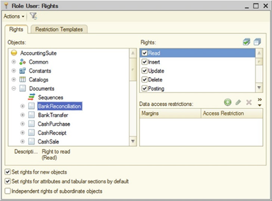
Fig. 82. Role access rights editor
The state of the Set rights for new objects checkbox determines whether the rights for this role will be set for the newly added configuration objects (removed for the new role by default).
The state of the Set default rights for attributes and tables checkbox determines whether the rights for this role are set for attributes (including standard ones) and tables (including standard ones) for the new configuration objects (set by default).
When the state of the Set default rights for attributes and tables checkbox is changed, the user is proposed to change (set or reset) access rights for all the attributes (including standard ones) and tables (including standard ones) of all the configuration objects. If the proposed action is refused, there are no changes in the existing objects, and the default behavior for new objects is changed only.
When creating a new role, all the rights are set by Designer as follows:
-
No rights for objects are set.
-
Rights are set for attributes (including standard ones) and tables (including standard ones).
The Independent rights for subordinate objects checkbox determines how the 1C:Enterprise will take consider the state of rights for the parent object when determining the rights for a subordinate object. If the box is checked, the rights for the parent object are considered. If the checkbox is cleared, when determining the right for a subordinate object, the corresponding right for the parent object is analyzed. If the parent object has no right, the subordinate object has no right also, regardless of the state of the right for the subordinate object.
TheIndependent rights for subordinate objects checkbox does not lift the requirement for having the same right for the parent object as for the subordinate one. That is, for an attribute or a table, the user must have the right for the object. For a table attribute, the user must have the right for the table and the object. This property has an effect if the user has several roles whose rights are combined "by OR". That is, if the Independent rights for subordinate objects property is set in a role and there is a right for the attribute only, and another role has a right for an object only, then after combining the rights of roles, the user will have the right to attribute
When assigning access rights for attributes (tables) of reports/data processors, consider one peculiarity. If the Independent rights for subordinate objects checkbox is cleared for the role and the Edit right is set for an attribute (table), but the View right is not set for its report/data processor, the Edit right is not set for such attribute (table).
If a user is assigned several roles, then the rights for the parent object are checked before a combination of rights by roles is performed (to determine the resulting rights to the object), see Role combination rules.
The Independent rights for subordinate objects checkbox effect is applied to the following objects:
-
Attributes (including standard ones)
-
Tables (including standard ones)
-
Table attributes (including standard table attributes)
-
Commands
To change the access right, select the configuration object in the left list, and change the state of the checkbox in the required action type row in the right list. If it is required to change access to all the objects of the selected branch at once, specify this branch in the left pane and change the access rights setting.
The description of each role can be displayed in a spreadsheet or text document by clicking Actions > Output list.
5.5.4.7. Viewing and editing all roles
If several roles are used in the configuration, it is recommended to use the All roles window for ease of viewing and editing the rights. To open it, specify the Roles branch in the configuration object tree of the Configuration window and select the All roles command in the context menu.
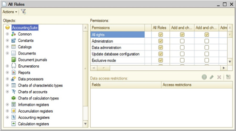
Fig. 83. "All roles" editing window
The window has three tabular fields. In the first (to the left), the desired configuration object is selected. The first column of the second tabular field displays a list of rights for the selected object. Other columns are intended to indicate the use of each right for each existing role.
If it is required to set or remove all rights for any role, it is enough to check or uncheck the permission box in the first row of the tabular field.
If it is required to check or uncheck the permission box in all the roles for some right, it is enough to check or uncheck the permission box in the first column of the tabular field.
The possibility to rearrange columns corresponding to roles is supported.
The third tabular field allows you to edit data access conditions at the level of individual fields and records.
5.5.4.8. Data access restriction
5.5.4.8.1. General notes
The data access restriction functionality allows you to manage access rights not only at the level of metadata objects but also at the level of 1C:Enterprise database objects. To restrict access to data, the following 1C:Enterprise objects can be used:
-
Roles
-
Session parameters
-
Functional options
-
Privileged common modules
-
ALLOWED keyword in the query language
Joint use of these objects allows for maximum flexibility when it is necessary to differentiate data access rights between users who perform various functions.
Data access restrictions can be imposed on the following data operations (access rights): reading (Read right), adding (Add right), editing (Edit right), and deleting (Delete right). The current user will be able to perform the required operation in the following cases:
-
For reading and deletion operations, the object in the database must comply with the data access restriction.
-
For the adding operation the object that is to be written to the database must comply with the data access restriction.
-
For a change operation, the object both before the change (for the object to be read) and after the change (for the object to be written) must comply the data access restriction.
When imposing data access restrictions, it must be noted that only one condition can be set for changing, adding and deleting operations, and more than one data access restriction can be set for a reading operation. This means that different conditions can be set to read different fields of an object, and when specifying a condition, you can specify both the name of a specific field and the Other fields special field. In the first case, the condition will be imposed only if the selection (using which the data is read) has a field for which the restriction is set, and in the second case the restriction is imposed to all fields of the object, except the fields for which the restrictions are explicitly specified.
When setting a restriction for a specific field, this field will be read if the restriction is met, and when setting a restriction for Other fields, the object data will be read only if the restriction is met for all the fields of the object that fell into the data read request.
For database objects of the following types, various restrictions can be imposed on different types of changes (addition, changing, deletion):
-
Exchange plans
-
Catalogs
-
Documents
-
Charts of characteristic types
-
Charts of accounts
-
Charts of calculation types
-
Business processes
-
Tasks
For the following types of database objects, it is possible to impose restrictions on reading of not only the entire object, but also its individual fields:
-
Exchange plans
-
Catalogs
-
Documents
-
Document journals
-
Charts of characteristic types
-
Charts of accounts
-
Charts of calculation types
-
Information registers
-
Business processes
-
Tasks
Note. IMPORTANT. When accessing the fields of database objects using the properties of applied objects from the 1C:Enterprise language, the entire object is read, and not just the value of the field used. The exception is getting the presentation where only the values of the fields involved in the generation of the presentation are read.
Access restrictions are contained in roles; these can be specified for most metadata objects and are written in a special language, which is a subset of the query language.
5.5.4.8.2. Data access restrictions language
General information
Data access restrictions are described in a special language, which is a subset of the query language (for details of thequery language, see Query language). The data access restriction language has the following changes in comparison to the query language:
-
In a data access restriction request, there is always one table as a data source. This is the table of the object on which the restriction is imposed (the main restriction object).
-
Brief query description. Data access restriction language uses query language sections FROM and WHERE only. Thus, the description of the query language is as follows:
SELECT [ALLOWED] [DISTINCT] [TOP <Count>]
<Selection
field list>
[FROM ]
[WHERE <Filter condition>]
[GROUP BY <Grouping fields>]
[HAVING <Filter condition>]
[FOR UPDATE [<Top level table list>]]While the description of the data access restriction query language is as follows:
<Query description>
[Main restriction
object table alias]
[FROM ]
[WHERE <Filter
condition>]For the sources list details, see Query source description. For the filter condition details, see Filtering query results. Note that nested queries used in the data access restriction language provide limited capabilities (see Nested queries).
-
You can specify session parameters (see Session parameters) and functional options (see Functional options) as condition elements.
-
You can use templates that simplify writing restrictions at any point of the data access restriction request (see Access restriction text templates).
The main section of the restriction is the condition that is calculated for each database table record, on which the data access restriction is imposed. A record is considered available if a non-empty table (that is, a table with 1 or more records) is retrieved as a result of a condition application for a single record of the main restriction object table. If, as a result of the condition application, an empty table is retrieved, the record, for which the condition has been met in this way, is considered unavailable. Moreover, a change in the main restriction object table record is considered valid if the record does not contradict the restriction specified for the right, both before the execution of the change operation and after the execution of this operation.
Table fields
In data access restrictions, you can use:
- Object table fields for which the data access restrictions are described.
For example, if a restriction is imposed on the reading of elements of the Counterparties catalog, then the restriction may use the fields of the Counterparties catalog and its tables. In particular, the simplest restrictions on the reading of the Counterparties directory elements may be as follows:
WHERE Name = "Brick Factory"Or like that:
WHERE
Products.Description = "Red brick"Where Products is a table of the Counterparties catalog.
- Fields of object tables accessible by references in the main restriction object.
For example, if the MainManager attribute of the Counterparties catalog has the type of reference to the Users catalog, then the access restriction may, for example, be as follows:
WHERE MainManager.Code
= "Smith"Or:
WHERE
MainManager.Individual.Description = "Anderson"- Fields of object tables associated with the main restriction object by certain conditions and expressions over them.
For example, the following restrictions may be imposed on the reading of the Counterparties catalog elements:
Counterparties
FROM
Catalog.Counterparties
AS Counterparties
LEFT JOIN Catalog.Users
AS Users
ON
Counterparties.MainManager.Description = Users.Description
WHERE
Users.Individual.Description = "Anderson"This restriction uses the Users catalog element fields associated with this element in the Counterparties catalog by the value of the Name fields.
Nested queries
Nested queries are used to generate record sets that can be used to:
-
Link the main restriction object to the table.
-
Use as an operand in the IN or NOT IN comparison operations.
Nested queries can use any query language tools, except:
-
IN HIERARCHY operator
-
TOTALS expression
-
Nested query results cannot contain tables
-
Some virtual tables, in particular BalanceAndTurnovers
In the following example of the restrictions on reading from the Counterparties catalog, the nested query is used as a set of records for linking to the main restriction object:
Counterparties
FROM
Catalog.Counterparties
AS Counterparties
LEFT JOIN
(SELECT
Users.Description.Users.Individual
FROM
Catalog.Users AS Users
WHERE
Users.Code > "Franklin") AS Users
ON
Counterparties.MainManager.Description = Users.Description
WHERE
Users.Individual.Description = "Anderson"The following example shows the restriction on reading from the IndividualPassportDetails catalog, where the nested query is used as an operand of the IN comparison operation:
IndividualPassportDetails
WHERE
IndividualPassportDetails.Individual
IN
(SELECT DISTINCT
Workers.Individual AS Individual
FROM
InformationRegister.Workers AS Workers)If a nested query must retrieve data from the table, refer directly to the table in the FROM section of the nested query. For example, instead of:
SELECT
Ref AS Ref, Products.Description AS ProductsDescription
FROM
Catalog.CouterpartiesAs a query nested in a restriction, use the following:
SELECT
Ref AS Ref, Description AS ProductsDescription
FROM
Catalog.Counterparties.ProductsSession parameters
The data access restriction queries may include session parameters.For example, the following access restriction can be set for reading the elements of the ElectronicMailGroups catalog:
WHERE
Owner.AccountAccess.User = &CurrentUser
AND Owner.AccountAccess.Administration = TrueWhere CurrentUser is a session parameter (see Session parameters).
Functional options
The data access restriction queries may include functional options. Parameter-independent functional options can be used only. For example, if the Products catalog has a MainWarehouse attribute, then the restriction on reading this attribute may be as follows:
WHERE
&AccountingByWarehouses = TrueWhere AccountingByWarehouses is a functional option (see Functional options and functional option parameters).
Specifications
Not all the fields of the main restriction data object can be used in the restrictions on database objects of the following types:
-
In accounting registers, only balance dimensions of the main restriction object can be used in restrictions.
-
In accumulation registers, access restrictions can contain only dimensions of the main restriction object.
If the conditions of access restriction to the turnover accumulation register data use dimensions that are not included in the totals, then when accessing the virtual turnover table, the stored totals are not used and the query is executed completely according to the movements table.
- In information registers, access restrictions can contain dimensions, resources, attributes, the Period and Recorder standard attributes, and any common attributes that include a register.
When you use object access from 1C:Enterprise language, access is requested to all register fields. So, access to register data will be granted when access is granted to all the fields with specified data access restrictions (conditions are combined "by AND").
When you write a register record set, only data access restrictions on modification are applied. All auxiliary actions are performed in privileged mode. Check record set validity and key value uniqueness before you change register table data and check data access restrictions on modification. Data access restrictions on reading are not applied.
Restrictions for individual fields are applied only when you read the register using a query (including in a dynamic list). When you access the SliceFirst and SliceLast virtual tables, restrictions are applied only to the fields that are used in the query. Restrictions are not applied to dimensions, recorder fields, and period fields, which are used only for virtual table implementation.
5.5.4.8.3. Access restriction actions
Access restrictions are checked when any relevant operations are performed on database objects (from dialog boxes, from the 1C:Enterprise language, through queries) and may act in one of two methods:
-
All. The "all" method implies that some operation on the data (from dialog boxes, from the 1C:Enterprise language or through queries) must be performed on all database objects implied by the operation. If during such an operation the database objects, for which the corresponding access restrictions are not met, are to be read or modified, the operation fails due to an access violation.
-
Allowed. The "allowed" method implies that only database objects that meet the relevant access restrictions must be read when performing an operation with data. Database objects that do not meet the access restrictions are considered absent when performing such an operation and do not affect the result of the operation.
Data access restrictions are imposed on database objects at the time when 1C:Enterprise addresses the database. In 1C:Enterprise client/server mode, restrictions are set on 1C:Enterprise server.
The mode of restrictions effect chosen to perform each operation on data is determined by the purpose of this operation and the responsibility degree of its results. In particular, the "allowed" method is used when displaying dynamic lists and some other interactive actions. The "all" method is used when performing any operations with applied objects using 1C:Enterprise language, including any changes to database objects. Therefore, for example, it may be difficult to build a selection for the Select() method of catalog, documents and other managers, and then bypass the result if quite a complex restriction is imposed on the corresponding object, since not all the conditions for access rights restriction can be adequately represented as a selection for the Select() method.
In queries, you can control how data access restrictions work. For this purpose, the query language provides the ALLOWED keyword. If ALLOWED is not specified in the query, the restrictions are applied using the "all" method. If the ALLOWED word is indicated, the "allowed" method is selected.
If the query does not specify the ALLOWED keyword, all filters specified in this query cannot contradict any of the restrictions on reading database objects used in the query. In addition, if the query uses virtual tables, then the corresponding selections must be imposed on the virtual tables themselves.
Example:
SELECT
ContactDetailsSliceFirst.Presentation
FROM
InformationRegister.ContactDetails.SliceLast(, Type = &Type)
AS ContactDetailsSliceFirst
WHERE
ContactDetailsSliceFirst.Type = &TypeWhen using object method, data access in the ALLOWED mode is not supported. It is assumed that the object method is used for the most important data operations, including data modification. To retrieve all the data using the object method, regardless of the existing restrictions, the necessary actions can be performed in a privileged module or by a full-access user. There is no means of retrieving only permitted data using the object method.
5.5.4.8.4. Feature for setting restrictions
Any operation on data stored in the database in 1C:Enterprise ultimately results in accessing the database with some query to read or modify the data. When executing queries to the database, internal 1C:Enterprise tools impose access restrictions. In addition:
-
A list of rights (read, add, change, delete), a list of database tables and a list of fields used by this query are generated.
-
Data access restrictions are selected from all the roles of the current user for all the rights, tables and fields involved in the query. At the same time, if any role does not contain restrictions on access to the data from any table or field, this means that the values of the required fields from any record are available in this table. In other words, the absence of a data access restriction means the presence of WHERE True restriction.
-
The current values of all the session parameters and functional options involved in the selected restrictions are retrieved.
To retrieve the value of the session parameter from the current user, the right to retrieve this value is not required. However, if the value of a certain session parameter was not set, an error will occur and the database query will not be executed.
The retrieval of functional options is affected by the functional option Privileged mode upon retrieval property (see Functional options and functional option parameters). If this property is reset, the current user must have read permissions on the object which stores the functional option.
-
Restrictions derived from one role are combined by AND operation.
-
Restrictions derived from different roles are combined by Or operation.
-
The generated conditions are added to the SQL queries used by 1C:Enterprise to access the DBMS. When accessing data from the access restriction conditions, the rights are not checked (neither to metadata objects, nor to database objects). Moreover, the feature for adding conditions depends on the selected restriction mode: "all" or "allowed".
"All" method
When imposing restrictions using the "all" method, conditions and fields are added to SQL queries so that 1C:Enterprise can obtain information on whether the data that was restricted to this user was used when executing a database query. If the forbidden data has been used, the query is terminated abnormally. In the figure, you can see how to set access restrictions using the "all" method:
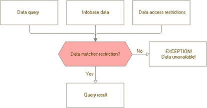
Fig. 84. "All" method
"Allowed" method
When restrictions are imposed using the "allowed" method, such conditions are added to SQL queries, so that entries that are restricted to the current user did not affect the query result. In other words, when restrictions are imposed in the "allowed" mode, records restricted to this user are considered to be missing, which is schematically shown in the figure:
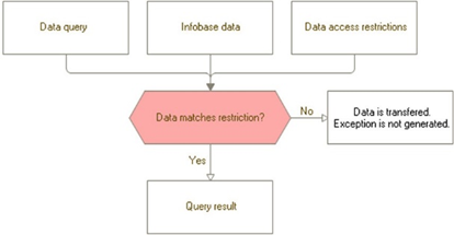
Fig. 85. "Allowed" method
5.5.4.8.5. Other objects related to data access restrictions
When developing configurations using data access restrictions, metadata objects such as session parameters, functional options and common modules with the Privileged checkbox may be useful.
Session parameters
Session parameters can be used in data access restrictions in the same manner as the query parameters can be used in a query.Functional options
Parameter-independent Functional options can be used in data access restrictions in the same manner as the query parameters can be used in a query.Privileged common modules
If the Privileged checkbox is selected for the common module, the execution of the procedures and functions of this module acquires important specific features:-
Only the module that runs on the server can be privileged in the client/server mode of 1C:Enterprise.
-
Execution of procedures and functions of the privileged module and everything, that is called from them, is performed when the feature of rights restriction to both metadata objects and data is disabled. Thus, any operation on any objects can be performed from the privileged module, even if the current user does not have the corresponding rights.
Privileged modules are intended to initially set the values of session parameters used in data access restrictions. The common modules can be also used for some integral operations with data by a user with limited rights. For example, if the user function includes entering and posting the documents, but the user must not have access to data that is affected by the posting of the document, the execution of the posting operation can be passed to a privileged module. This will allow the user to post the documents without giving them the rights to other information (for example, registers).
Privileged mode
It is possible to programmatically set Privileged mode when working with data. The programmatical setting of the Privileged mode may be required in case of massive operations with the infobase data, and when it does not make sense to check the data access rights. For the description of Privileged mode, see Privileged operation mode.5.5.4.8.6. Preprocessor use
When editing the data access restriction text, it is possible to use preprocessor commands. The following commands are available:
#IF <Expression>
#THEN
#ELSIF
<Expression> #THEN
#ELSE
#ENDIF<Expression>. Arbitrary logical expression in 1C:Enterprise language, the result of which is of the Boolean type. The expression may contain:
-
Comparison operations: <, >, <=, >= , =, <>.
-
Logical operations: AND, OR, or NOT.
-
Session parameters. The &Parameter syntax is used, where Parameter is a session parameter name.
If the result of the #IF or #ELSIF command expression is True, the text following the #THEN keyword is included in the resulting access restriction command text. If the result of the expression is False, then the text following the #THEN keyword is not included in the access restriction command text. If none of the earlier conditions are met, the resulting access restriction command text will include the text following the #ELSE command.
Note. Note. If the data access restriction text contains preprocessor commands, such restriction does not pass the syntax check during editing and cannot be changed using the wizard.
Example:
#IF &CurrentUser
<> "Collins" #THEN
<access restriction
text>
#ENDIFHere, CurrentUser is a session parameter of the CatalogRef.Users type.
This statement means that the condition for setting access restrictions will be checked for all users from the catalog, except the user Collins.
5.5.4.8.7. Access restriction text templates
A role can contain a list of access restriction templates, which are described in the Restrictions templates role form tab. Access restriction templates can also be edited in the access restrictions and templates batch editor (see Batch editing of access restrictions and templates).
Each access restriction template has a name and a text. Template name must comply with the naming conventions of 1C:Enterprise.
Template text contains a text section written in the data access restriction language and can contain parameters marked with the "#" character.
The "#" character can be followed by:
-
One of the keywords:
-
Parameter, followed by the parameter number in the template in parentheses.
-
CurrentTable indicates the insertion into the text of the full name of the table, for which the restriction is being generated.
-
CurrentTableName indicates the insertion into the text of the full name of the table (as a string value, in quotes), which the instruction is applied to, in the current version of the 1C:Enterprise language.
-
CurrentAccessRightName contains the name of the right for which the current restriction is applied: READ, INSERT, UPDATE, and DELETE.
-
-
Template parameter name indicates insertion into the restriction text of the corresponding template parameter.
-
"#" character means inserting a single "#" into the text.
The access restriction expression may contain:
-
Access restriction template, which is specified in the #TemplateName("Template parameter value 1", "Template parameter value 2"...) format. Each template parameter is enclosed in double quotes. If required to specify a double quote character in the parameter text, two double quotes must be used.
-
Function StrContains(SearchWhere, SearchForWhat). The function is intended to search for SearchWhere string in SearchForWhat string. Returns True if the string is found and returns False otherwise.
-
- operator for string concatenation.
For the ease of template text editing click the Set template text button in the role form on the Restriction templates tab. Enter the template text in the dialog box and click OK.
The 1C:Enterprise will check the syntax of template text, template usage and check the macro substitution of the role access restriction template texts in the query text.
Template macro substitution includes the following operations:
-
Replacing parameters in the template text with parameter values from the template use expression in the restriction text.
-
Replacing the template use expression in the query text with the resulting template text.
When calling the query wizard for a condition containing access restriction templates, a warning is displayed about replacing all the templates.
Examples of restriction templates are shown below:
| Template name | Template |
| Template body | Total = #Parameter(1) |
| Use | Where #Template("10") |
| Result | Where Total = 10 |
| Template name | Template1(DocumentKind) |
| Template body | DocumentKind = #DocumentKind |
| Use | Where #Template1(""Invoice"") |
| Result | Where DocumentKind = "Invoice" |
| Template name | Template2 |
| Template body | DocumentKind = #Parameter(1) ## #Parameter(2) |
| Use | Where #Template2(""Invoice"", ""1"") |
| Result | Where DocumentKind = "Invoice # 1" |
| Template name | Template3 |
| Template body | DocumentKind = #Parameter(3) |
| Use | Where #Template3("","",""Invoice"") |
| Result | Where DocumentKind = "Invoice" |
5.5.4.8.8. General recommendations for restricting rights
In order to flexibly manage user data access in accordance with functions when setting data access restrictions, it is recommended to comply with the following principles:
-
It is necessary to choose a set of information (may be dependent on the current user) for which preliminary preparation is appropriate. The selected information must, on the one hand, simplify data access restrictions as much as possible, and on the other hand, must not be too large. Distribute it to the session parameters.
-
Set the values of the session parameters in the SessionParametersSetting() session module handler.
-
Set access restrictions to the data for which this is justified (the data are secret or most important to preserve the 1C:Enterprise integrity). Note that setting access restrictions can slow down any access to this data. The excessive complexity of the restrictions can cause a performance decrease.
-
If it is necessary to ensure that a certain number of operations are performed on data by the user, for whom it is impractical to give full access to this data, pass these operations to privileged modules or explicitly turn privileged mode on and off at the appropriate sections of the program code (see Privileged operation mode).
-
Data access during various checks performed by 1C:Enterprise when writing objects is executed in privileged mode (see Privileged operation mode). This allows you not to disable rights restrictions at the record level for the corresponding fields if the configuration operation with this data is planned in the managed mode only:
-
For catalogs when checking the parent, owner and uniqueness of the code.
-
For documents, business processes and tasks when checking the uniqueness of the number.
-
For exchange plans it is disabled when checking the uniqueness of the code.
-
For charts of accounts and carts of characteristic types when checking the parent and the uniqueness of the code.
-
When creating a data restriction query, some limitations and features must be noted:
-
If data access restrictions are set for an object table and the data query uses joining with such table, an object table with the specified access restriction cannot be used in the join condition (the BY query section).
-
If the query contains a table in which the query does not use any fields, then all the data access restrictions are imposed on this table. For example, SELECT COUNT(*) FROM Catalog.Counterparties query will be executed with consideration of all the access restrictions specified for the Test catalog. Restrictions are imposed "using OR logic". This means that all the records that are accessible by at least one condition will be available. If conditions are not specified for any fields, the query will be executed for all the records in the table.
If the query uses a top-level table, then the restrictions specified for the columns of nested tables are not imposed.
If the query uses a nested table, then restrictions are imposed on both nested and top-level tables. For example, SELECT COUNT(*) FROM Catalog.Counterparties.Contracts query will be executed considering all the restrictions for the Counterparties catalog and the restrictions related to the Contracts table.
- If access to the fields necessary to retrieve the reference metadata object presentation is denied using data access restrictions or access to an object is denied at the level of access rights, then retrieving a presentation of such object does not affect the progress of the current transaction.
5.5.4.8.9. Data access restriction wizard
To call the wizard go to edit mode and click the select button in the Data access restrictions table filed, in the Access restriction column, and click the Request wizard... button in the opened form.
The wizard form is displayed:
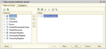
Fig. 86. "Tables and fields" tab of the restriction wizard
Creation of conditions for setting data access restrictions is performed using it.
In the Tables and fields tab, select the necessary objects in the Database list and move them to the Tables list. If several tables are specified, the Links tab is added to the wizard form.
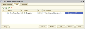
Fig. 87. "Links" tab of the restriction wizard
The Links tab enables you to specify the criteria for the links between the table fields. To enter a new condition, click the Add button and select one of the tables in the Table1 column. Select a table whose fields are linked to the fields of the first table in the Table2 column. Controls that are used to create table link criteria are located below the criteria list.
If a simple condition type is selected, then the related fields of the specified tables are selected in Field1 and Field2 and the comparison condition is set. If you select fields not to be compared, you will see the Incorrectly completed condition warning in a condition list row, in the Link condition column.
Specify the conditions using which the source data will be selected in the Conditions tab, if so required.
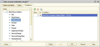
Fig. 88. "Conditions" tab of the restriction wizard
For each selected field, it is required to choose the type of condition and specify the parameter name. A session parameter is allowed to be used as parameter. Several conditions are allowed. In this case, the condition text is displayed in several lines in the Condition column of the condition table field.
You can review the query text anytime during query creation by clicking Query button.
5.5.4.8.10. Batch editing of access restrictions and templates
The batch access restrictions and templates editing mode is called using All access restrictions command from the context menu of the Roles branch. The displayed form contains two tabs: Access restrictions and Restriction templates.
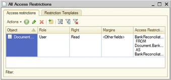
Fig. 89. All access restrictions and templates
In the Access restrictions tab, you can view all entered access restrictions in the common list (for all roles, objects, rights, and combinations of fields).
There is a possibility to add access restrictions for several roles, objects, rights and combinations of roles at once.
It is possible to filter the list by various criteria.
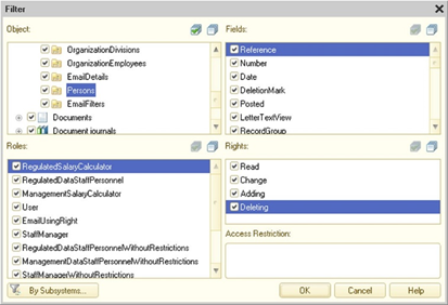
Fig. 90. Access restriction filter
The batch editing mode allows removing the restrictions selected in the list.
You can edit the selected restrictions. At the same time, it is possible to replace the field components and/or access restriction.
The batch editing mode also allows copying the selected restrictions to other roles.
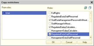
Fig. 91. Copying restrictions
In the Restriction templates tab, it is possible to see all the access restriction templates, available in the application, while the table only shows the first 10 lines of the template text itself, which end in the "..." character, if the template text contains is more than 10 lines. The full template text will be displayed in the template editing window.
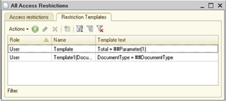
Fig. 92. All access restriction templates
It is possible to add an access restriction template to several roles at once.
It is possible to select the necessary templates using a set of criteria, as well as by the value of the current column.
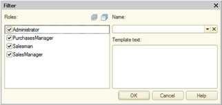
Fig. 93. Access restriction template filter
If required, it is possible to copy one or more templates to other roles.
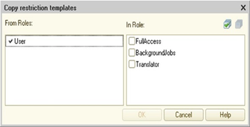
Fig. 94. Copying templates
With the editor, you can also edit the selected templates. In this case, you can change the name and the text of the template itself.
5.5.5. Common attributes
A common attribute is an attribute added to all or many configuration objects. You can use common attributes in two scenarios:
-
As a common attribute, that is, to simplify specifying the attribute that is present in all or many configuration objects where this attribute retains its meaning and type. An arbitrary comment field in the application documents is an example of such common attribute use.
-
As a component of the data separation, a special feature that allows dividing all the stored data, as well as the application operation, into separate parts. In this case, data separation is enabled for the common attribute. An example of such use is the concept of a subscriber, when different data "owners" can operate independently in one physical infobase, while the users of such application will think, that there is nothing more in the infobase except "their" data. For more information on data separation feature, see Data separation feature.
In order to create a common attribute, it is necessary to create a Common attribute configuration object. You can do it in Designer mode in a standard way. In the configuration window, select the Common item, then Common attributes and add a new object.
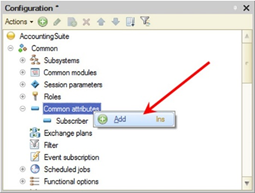
Fig. 95. Creating common attribute
As a result, the Common attribute configuration object will be created, which can be used to include the common attribute in the necessary configuration objects.
The common attribute mode of operation is set using the Data separation property. If this property is set to Do not use, then the created configuration object will be used only as an attribute, included in several (or all) configuration objects. If the property is set to Separate, the common attribute will be used as a data separator (see Data separation feature).
The list of configuration objects that include the common attribute is determined using the Components and AutoUse properties (or the corresponding tab in the Advanced window (see "More" window)).
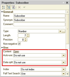
Fig. 96. Common attribute without separation
If the AutoUse property is set to Use, then the created common attribute will be automatically added to all existing configuration objects (for which it is possible to use common attributes), and will also be automatically added to all newly created configuration objects.
If the AutoUse property is set to Do not use, there will be no automatic adding of the attribute, and the Components property will be used to select the objects where the common attribute must be included.
This same property must be used if there are objects in the automatic use of the common attributes where the common attribute must not be added.
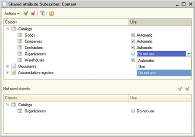
Fig. 97. Common attribute components
The window for editing the common attribute components is divided into two parts:
-
The top section lists all the configuration objects that may be included in the common attribute.
-
The bottom section contains the objects which settings differ from the default settings, determined by the value of the AutoUse property of the common attribute:
-
If the property is set to Use, the bottom section of the window contains a list of objects that are not included in the common attribute.
-
If the property is set to Do not use, the bottom section of the window contains a list of objects included in the common attribute.
-
Editing can be done both in the top and the bottom sections of the window, while the edited configuration object will move between the window sections, depending on the value in the Usage column.
For each configuration object, the Usage column can have one of three values:
-
Automatically means that the assignment of a configuration object to a common attribute depends on the value of the AutoUse property of the common attribute:
-
Use means that the configuration object is included in the common attribute.
-
Do not use means that the configuration object is not included in the common attribute.
-
-
Use means that the configuration object is included in the common attribute regardless of the value of the AutoUse property.
-
Do not use means that the configuration object is not included in the common attribute, regardless of the value of the AutoUse property.
Thus, using the Components property editor, it is possible to, for example, selectively exclude some objects from the common attribute, despite the fact that the automatic use is set for it.
The common attribute (not in the data separation mode) may include the following configuration objects:
-
Catalogs
-
Documents
-
Sequences
-
Document journals
-
Charts of characteristic types
-
Charts of accounts
-
Charts of calculation types
-
Recalculations
-
Business processes
-
Tasks
-
Information registers
-
Accumulation registers
-
Accounting registers
-
Calculation registers
-
Exchange plans
-
External data sources
When writing a document, the journal common attribute is assigned the value of the common attribute of the document or the NULL value if the document is included in the common attribute.
Common attribute can be used in data access restrictions (see Data access restriction). It makes sense to include external data sources in the common attribute if the common attribute is a separator (see Data separation feature). The peculiarities of using the external data source included in the separator can be found in the corresponding section (see External data sources).
A common attribute can be of a union type.
Note. TIP. Using common attributes to describe data that is part of the business logic of specific objects must be avoided.
Common attributes are displayed in the form editor when editing the object forms included in the common attribute, and can be placed on the form.
5.5.6. Exchange plans
Exchange plan is used to implement data exchange features. Exchange plan:
-
Contains information about nodes that can participate in data exchange.
-
Determines the data to be exchanged.
-
Indicates whether the distributed infobase functionality must be used during the exchange.
One application can have several exchange plans, each of which may describe its own data exchange procedure. For example, if data is exchanged with remote warehouses and remote offices, then there will most likely be two exchange plans (one is for data exchange with warehouses, the other is for data exchange with offices), since the data that is exchanged with warehouses will be significantly "narrower" than the data intended for exchange with the offices.
For a description of data exchange tools, see Data exchange features.
5.5.7. Filter criteria
Filter criteria is one of the components of the data filtering functionality. Using these, the 1C:Enterprise configuration specialist creates predefined filtering rules. In 1C:Enterprise mode, these rules will be used to filter the information in lists.
It is necessary to specify a name, a synonym and a comment in the Filter criteria object editing window.
The type of filter criteria can be any of the standard types or defined as the configuration tree objects. You can include attributes with a union type specified as CatalogRef, DocumentRef, and so on, and as attributes with a union type defined by the chart of characteristic types (Characteristic…).
When creating a type of filter criteria, it is necessary to specify the types which are used for filtering. Based on this type in the Components tab, the configuration objects composition will be generated, which contain data of type included in the filter criteria type. It is necessary to set a mark in the list for those attributes, by which this filtering will be performed.
For the filter criterion to fulfill its functions, a list must be created for it in the Designer (the Components tab) consisting of the catalog and document attributes. There are practically no restrictions when it comes to list components. For example, in contrast to the journal column, you can select several document attributes and attributes of a document table for a filter criterion.
There may be an arbitrary number of filter criteria, and each criterion can have several forms for presenting the filter results. This feature is useful when searching for various information. For example, it is required to select all the documents where a certain counterparty (in attributes and tables) is used. In this case, you can consider other information filter conditions. For example, the search is performed only among posted documents or within a certain period, and so on.
Note. Note. When opening the filter form, it is necessary to pass the Filter parameter to it with the set filter value (Value element).
The filter criterion can have an arbitrary number of forms for visual presentation of the filter results. For prompt retrieving the filter information, the form call can be placed in the user menu or on the toolbar.
If there are several forms of the filter criterion, then the Main form property indicates the form that will be called by default.
If there are several subsystems defined in the configuration, it is necessary to select the one which this filter criterion belongs to. Several different subsystems can be specified.
To call the filter criteria form, 1C:Enterprise system places the corresponding command in the form navigation panel.
5.5.8. Event subscriptions
Event subscriptions allow you to assign event handlers to a single object or a group of 1C:Enterprise language objects.
When adding a new event subscription, in addition to the common configuration object properties, it is necessary to specify the event source, the event, the handler of which is assigned, and the procedure that handles this event.
Applied objects, sets of register records, and configuration object managers can be event sources. Both multiple selection of objects that are event providers, and the selection of all objects of the same type (for example, all the documents) is allowed.
The event is selected from the drop-down list, where the list contains those events that are present in all the selected objects. If there are no such events, the list will be empty.
The event handler is selected in a window containing procedures that can be assigned as an event handler. Such procedures must meet the following requirements:
-
The procedure must be located in a common module.
-
The common module that contains the procedure must have the following properties set:
-
The Global checkbox is cleared.
-
The Client (ordinary application) checkbox is selected.
-
The Client (managed application) checkbox is cleared.
-
The Server checkbox is selected.
-
The External connection checkbox is selected.
-
-
The procedure parameters number must exceed the selected event handler parameters number by one. This is due to the fact that in addition to the parameters that are passed by 1C:Enterprise to the event handling method, the source object of this event is also passed.
When the specified event occurs, the following sequence of actions is performed:
-
First, the event is handled in the object itself and the event handler defined in the object or record set module is called. If the configuration extensions (see Configuration extension) are attached to the application, the program code extending the event handlers is also executed at this stage.
-
If the Fail parameter is set to True or an exception is thrown during the execution of the handler, the action is aborted.
-
Then the external handlers assigned to this event are called in an arbitrary order.
-
If the Fail parameter is set to True or an exception is thrown during the execution of the assigned handler, the action is aborted.
As a source, the object itself (record set) that caused the event is passed to the assigned handler.
The assigned event handlers are called in the same context as the action that triggered the event. If the execution of the assigned handler needs to be passed to the server, the common module procedure executed on the server must be called in the handler code.
The event handler assignment is also available using 1C:Enterprise language. For this the AddHandler and RemoveHandler operators are used.
Objects that can be event sources have the AdditionalProperties property of the Structure type. The property allows you to store information between event calls, for example, if this object is new or old.
5.5.9. Scheduled jobs
5.5.9.1. Main features of the job functionality
Main features of the job functionality are:
-
Determine scheduled procedures at the 1C:Enterprise programming stage.
-
Perform specified actions according to the schedule.
-
Call a procedure or function asynchronously without waiting for its completion.
-
Monitor the job progress.
-
Job management (cancel, lock the execution, and other).
-
Wait for the completion of one or more jobs.
5.5.9.2. Background jobs
The background jobs feature is implemented using the 1C:Enterprise language. Background jobs are intended to perform application jobs asynchronously. These can generate child background jobs, for example, for paralleling complex computations across different working servers in a cluster in a client/server mode.
It is possible to limit the execution of background jobs with the same methods based on a certain applied characteristic. Programmatic creation and management of background jobs is possible from any user connection to the 1C:Enterprise infobase. The background job is run as the user who created it.
5.5.9.3. Scheduled jobs
Scheduled jobs are an integral part of a specific application and are described at the configuration stage.
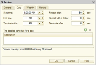
Fig. 98. Background job schedule
For each scheduled job a schedule can be set, according to which the scheduled job will be automatically started. The 1C:Enterprise supports one-time and periodic schedules. It is possible to set the start and end dates, daily, weekly and monthly schedules. The schedule can be set both at the configuration stage and at the execution stage (in the 1C:Enterprise mode).
In the process of starting, a scheduled job generates a background job, which performs the actual processing. The scheduled job can be executed as the specified user and has the possibility to be restarted (for example, in the event of an unexpected shutdown).
In the client/server administration utility the automatic execution of scheduled jobs can be prohibited for a specific infobase.
5.5.9.4. Scheduled job execution specifics
In the client/server mode, the scheduled jobs are started as per schedule by the cluster manager. Thus, even if no client connection is established to the infobase, scheduled jobs will be executed (provided that they are not prohibited for a particular infobase).
5.5.10. Functional options and functional option parameters
parameters5.5.10.1. Purpose
Functional options allow the developer to describe the features of the application, which can be quickly turned on or off during the deployment phase and/or during 1C:Enterprise operation. For example, the ability to process additional properties of goods can be distinguished into a separate functional option. Then, if this feature is disabled, all the related features (with additional properties of the goods) will be "lost" the application interface.
The 1C:Enterprise is able to automatically consider the state of the settings made to hide the disabled features, making the application interface clearer and more understandable for the user.
During the development, situations arise when the value of a functional option must depend on certain parameters, for example, not all the companies maintain currency accounting. To implement this dependency, the Functional option parameters are used, which are the objects that set parameters of the functional options.
5.5.10.2. What functional options affect
5.5.10.2.1. General information
The functional options may affect:
-
User interface when any functional options are turned off, the 1C:Enterprise system hides all items related to it in the user interface. This affects the following interface items:
-
Global command interface.
-
Form attributes (including form attribute columns of ValueTable or ValueTree type).
-
Form commands.
-
Reports implemented using the data composition system.
-
Note. Important. If the client application uses the file mode of the infobase via the web server, changing the functional option will only change the user interface after restarting the web server (restarting the client application will not cause user interface change).
- Algorithms written in the 1C:Enterprise language. There is a possibility to retrieve the functional option values from 1C:Enterprise language and use them under various conditions, for example, to reduce the amount of computation.
Note. IMPORTANT. Functional options and their parameters do not affect the database components. All the tables and fields are present in the database, regardless of the state of the functional options.
5.5.10.2.2. Global command interface
The effect of the functional options on the global command interface is that 1C:Enterprise hides the commands of all the objects related to the disabled options. For example, if the Purchases functional option value is False, the commands to open the Purchases section, to create the GoodsArrival document, to open the GoodsArrival list, and other, will be hidden.
In turn, the Purchases option may consider the functional option parameter value, for example, Organization. By changing the value of this parameter using the 1C:Enterprise language methods, it is possible to change the state of the functional option, and, consequently, the visibility of the interface item.
It is also necessary to consider the following peculiarities of the command interface generation:
-
The command will be excluded from the command interface in the event that the attribute, which is a parameter of the command, is disabled by the functional option.
-
The command will be excluded from the command interface if the command parameter type is disabled by the functional option. If the command parameter type is union, the command becomes unavailable when all the parameter types are disabled.
5.5.10.2.3. Forms
In the form, the functional options can affect form attributes and commands and (as a result) change the visibility of the associated form items (fields and columns for form attributes, buttons for form commands). When developing a form, it is necessary to consider the following peculiarities of 1C:Enterprise behavior:
-
The main attribute of the managed form of the <Type>Object type (CatalogObject, DocumentObject, and so on) will be disabled if the corresponding configuration object is disabled by the functional option. Only those functional options that have no parameters are analyzed.
-
The main attribute of the managed form of the DynamicList type will be disabled if the functional option disables the configuration object that is specified as the main table of the dynamic list. Only those functional options that have no parameters are analyzed.
-
Dynamic list that displays the document journal does not consider the fact that some of the document types in this journal are disabled by the functional option. The dynamic list will always display all the documents in the journal.
-
The reference type form attribute is disabled if the configuration object forming this type is disabled by the functional option. The union type form attribute is disabled if the functional options disable all the component types.
-
A form attribute of the <Type>Object type (including the main form attribute) is disabled if the configuration object forming this type is disabled by the functional option. Only those functional options that have no parameters are analyzed.
-
The form table will be disabled if it displays the data of the form attribute disabled by the functional option.
-
There are no types in the type selection dialog box (for example, for input fields associated with the union type attributes), if the configuration objects that form these types are disabled by the functional option. Information about types that are disabled by functional options is cached on the client side and cleared after 20 minutes or during the call of RefreshInterface() method.
Note. IMPORTANT. Unlike the command interface, the functional options parameter values are set only for a specific form instance.
5.5.10.2.4. Data composition system
The data composition system is mainly used for reports generating. Functional options affect the data that is displayed in the report, and the report settings available to the user. For example, if the Foreign currency accounting functional option is disabled, the report displaying the Goods arrival document register will not include the Currency and Currency amount columns, and the settings will not allow you to filter, group, sort, and so on the Currency field.
For more information about how functional options affect field accessibility in reports built on a data composition system, see Functional options and report field view rights.
5.5.10.2.5. Characteristics
Functional options affect the visibility of form fields that display the object characteristic value. For this purpose, it is necessary to include an attribute that stores the value of the characteristic in the functional option.
Consider an example. Characteristics are used for the Goods catalog, types of characteristics are stored in Characteristics chart of characteristic types, and values as a CharacteristicValues information register resource. The resource is included in the CharacteristicsAccounting functional option.
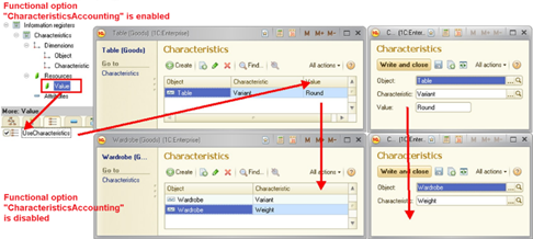
Fig. 99. Effect of the functional options on characteristics
If the CharacteristicsAccounting functional option is disabled, , the visibility of the fields (the Value column and the Value field), displaying the values of the characteristics in the forms is also disabled, as shown in fig. 99.
5.5.10.3. General operation procedure
The functional options feature includes two types of metadata objects: Functional option and Functional option parameters.
The functional option is a metadata object that can directly affect the application interface components (if the functional option stores its value in a Boolean attribute). Using objects of this type, it is possible to hide items that are related to unavailable functionality. For example, Currency accounting option may hide the Currencies catalog, Currency filed from the documents, Currency amount column from the reports. The source of the functional option value is the metadata object selected as the Storage property, for example, it can be a constant.
If the functional option value is stored in the catalog attribute or the information register resource, additional information is required, which indicates how to select the option value. For this purpose, a separate metadata object (Functional option parameters) is provided.
It can be said that the functional option parameters are the coordinate axes of the functional option value space. At the same time one functional option parameter can determine the value of "its" coordinate axis simultaneously for a variety of functional options.
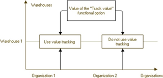
Fig. 100. Parameterizable functional option
For example, imagine that sum accounting depends on the warehouse owned by a particular organization (see fig. 100). In our infobase it is possible to keep records on behalf of various organizations and in different warehouses.
To store the values of the functional options, let us create an information register where dimensions (coordinate axes) will be:
-
Organization (of the corresponding type)
-
Warehouse (of the corresponding type)
Information register resource will be the value of the sum accounting functional option.
Then the general configuration structure will be as follows:
-
Information register SumAccounting:
-
Dimension Organization
-
Dimension Warehouse
-
SumAccounting resource of the Boolean type
-
-
Organization functional option parameter. Usage property indicates the Organization dimension of the SumAccounting information register.
-
Warehouse functional option parameter. Usage property indicates the Warehouse dimension of the SumAccounting information register.
-
SumAccounting functional option. Storage property indicates the SumAccounting resource of the SumAccounting information register.
As a result, in order to determine the need for sum accounting, it is necessary to specify the values of the functional option parameters (Organization and Warehouse) in each specific case and retrieve the functional option value.
So, in the example shown in fig. 100, the sum accounting is allowed for Organization 1 and Warehouse 1, and restricted for Organization 2 and Warehouse 1.
5.5.10.4. Interaction with other objects
Functional options can be assigned to the following configuration objects:
-
Subsystems
-
Common commands
-
Common forms
-
Constants
-
Filter criteria
-
Catalog
-
Document
-
Journal
-
Chart of accounts
-
Chart of characteristic types
-
Chart of calculation types
-
Business process
-
Task
-
Exchange plans
-
Report
-
Data processor
-
Accumulation register
-
Information register
-
Accounting register
-
Calculation register
-
Command
-
Metadata object attribute
-
Table
-
Table attribute
-
Accounting flag
-
Extra dimension accounting flag
-
Addressing attributes
-
Register dimension
-
Register resource
Functional options can also affect the visibility of form items.
5.5.10.5. Creating
5.5.10.5.1. Creating functional options
To create a functional option, create a Functional option configuration object. This can be done in the Designer mode in a usual way, that is, select Common item in the configuration window, then Functional options and add a new object.
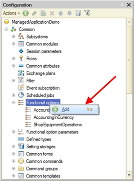
Fig. 101. Creating functional options
As a result, a Functional option configuration object will be created that can be used to assign functional options to other metadata objects.
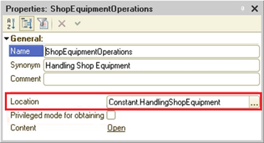
Fig. 102. Functional option value storage
In addition to the name, the object has a mandatory Storage property. In the editor, it is possible to select one of the objects for it, which will be the option value source. The list of available objects includes:
-
Constants
-
Catalog attributes
-
Information register resources
There is no restriction on the option value source type, but only those functional options that store their values in the attributes of Boolean type are suitable for controlling the interface. Functional option values with other types are available for analysis in the 1C:Enterprise language only.
The Privileged mode upon retrieval property is responsible for the method of retrieving (and caching) the functional option value.
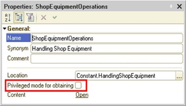
Fig. 103. Privileged mode when retrieving the functional option value
If this property is set, the functional option value is retrieved in the privileged mode. The retrieved value is cached for all the sessions related to this infobase.
If the Privileged mode upon retrieval property is reset, the functional option value is retrieved in normal mode. Caching is performed for the current session. Both the value (if it was retrieved) and the value retrieval impossibility flag (if the value could not be retrieved) are cached.
The cache is reset when the session parameters change.
Note. Tip. It is recommended that you set the Privileged mode upon retrieval property for all cases when the functional option value does not contain confidential information.
5.5.10.5.2. Creating functional option parameter
In order to create a functional option parameter, it is necessary to create a Functional option parameters configuration object. This can be done in the Designer mode in a usual way, that is, select Common item in the configuration window, then Functional option parameters and add a new object.
In addition to a name, the parameter has a mandatory Usage property. It contains a set of objects which values will determine how the functional option value will be selected. The list of available objects includes catalogs and information register dimensions. For each functional option parameter in this list, it is possible to select one catalog (from the entire list of catalogs) and one dimension for each information register.
Note. IMPORTANT. Using the same metadata object in several functional option parameters is not possible.
5.5.10.6. Use
5.5.10.6.1. Assigning to metadata objects
A metadata object (for example, a catalog) can be assigned to one or several functional options. To do this, use the Functional options property, which contains references to the functional options created in the configuration.
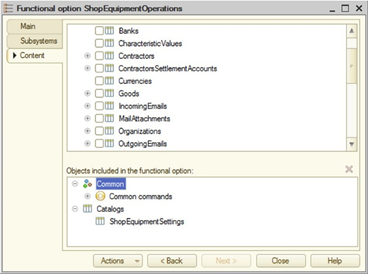
Fig. 104. Assigning the functional option to an object
The list of available options is limited only by those options which an object with the Boolean value type is assigned to in the Storage property.
Note. IMPORTANT. If no functional option is assigned to an object, it is always considered visible. Otherwise, the object is considered visible if at least one of the functional options assigned to it is enabled (that is, functional options are combined "using OR logic").
5.5.10.6.2. Assigning to form attributes and commands
Objects belonging to the form (Attributes and Commands) can also be used in the functional options functionality.
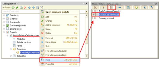
Fig. 105. Assigning the functional option to a command
This can be done in the form editor by setting the Functional options property for the required object.
The state of the functional options will affect the display of form objects in the same way as in case with metadata objects. For example, in case of a command that has been disabled using the functional option, all the associated buttons will be removed.
If no functional option is assigned to a form attribute or command, then a form attribute or command is always considered visible. Otherwise, the form attribute or command is considered visible if at least one of the functional options assigned to it is enabled.
5.5.10.6.3. Use in the data access restriction functionality
In terms of the data access restriction functionality (see Data access restriction), Functional options can be used in the same way as in the Session parameters (see Session parameters). It is permissible to use only parameter-independent options, that is, those that are bound to constants.
Note. IMPORTANT. The 1C:Enterprise controls the uniqueness of names between session parameters and functional options.
5.5.10.6.4. Determining function option values
The functional option value is determined by the object specified in the Storage property. In the case of a constant, its value is used. For the option associated with the catalog attribute or information register resource, the values are stored in these objects. To find a specific object that stores the functional option value, additional information is required, that is, a set of functional option parameter values.
If the option is stored in the catalog attribute, the parameter must contain a reference to a specific catalog item. When retrieving the functional option value, the deletion mark flag value of the catalog item that stores the functional option value is ignored. If the option is stored in the information register resource, the values of all the register dimensions must be specified. In this case, each dimension must be characterized by its own parameter.
If not all parameters are specified for a functional option of a Boolean type, then the addition of all the values with unset parameters "using OR logic" is performed. For example, if the functional option is stored in the information register with the Organization and Warehouse dimensions and only the Organization dimension is set, then the functional option value will be True, if at least one of the warehouses listed in the Warehouse dimension, has True as the functional option value.
For a functional option that has a type other than Boolean, the situation with not fully specified parameters causes generation of an exception.
1C:Enterprise language methods allow retrieving the option value, depending on the parameters passed and parameters set for the command interface or a specific form. In case when the value of an object specified in the Storage functional option property is changed in a transaction, the actual value of the functional option will be changed only after the transaction is completed. As long as the transaction is open, the functional option value will be equal to the value in effect at the time of the transaction start.
If the functional option is bound to the periodic information register resource, 1C:Enterprise uses a slice last to retrieve the option value. If it is required to retrieve the option value for any other date, it is necessary to specify a value for the Period (Period) functional option parameter, which is of the Date type that will be used as the date of slice. This parameter does not need to be created in the metadata. It is provided by 1C:Enterprise automatically.
When using parameterized functional options, the following peculiarities of behavior must be considered:
-
In the list forms, the attribute column associated with the parameterized functional option will be displayed if at least one enabled value of this functional option is stored in the infobase.
-
If it is required that the attributes associated with the functional options are disabled by default when opening the form, set the values of these parameters to values that are absent in the infobase. For catalogs, these are an empty reference. For information registers, these are dimension values for which there are no records. In this case, the functional option will be False.
-
If a group reference is specified as a parameter (if the functional option parameter type allows creating groups) and not an item reference, 1C:Enterprise behavior will be as follows:
-
if the attribute which stores the functional option value is used for both element and group, then the functional option value will be determined by the value of this attribute.
-
if the attribute which stores the functional option value is not used for a group, then retrieving the functional option value using the GetFunctionalOption(), GetFormFunctionalOption() and GetInterfaceFunctionalOption() method, the NULL value is returned. If the functional option parameterized by this value affects the user interface, 1C:Enterprise will perceive it as disabled one (the functional option will be False).
-
-
For command-generating metadata objects, it is possible to set a binding to a parameterized functional option. In the command interface the commands of such objects will be displayed only if there is at least one combination of functional option parameters, where the functional option value is True. However, using the SetInterfaceFunctionalOptionParameters() method, it is possible to set specific functional option parameter values, and the visibility of commands will be determined by the specified parameters.
-
The dynamic list automatically uses the functional options used by the form. If the attributes that are used in the dynamic list query are disabled for a set combination of functional option parameters, the data for them will not be filtered and displayed in the dynamic list, and the attribute will be removed from the lists of available attributes in the dynamic list data display settings dialog box (in 1C:Enterprise mode).
5.5.10.7. Managing functional options in 1C:Enterprise language
TheGetFunctionalOption() and GetInterfaceFunctionalOption() global context methods return the functional option value. The difference between these two methods is that the first method allows you to specify a set of functional option parameters, and the second one returns the functional option value based on the parameters specified for the command interface. The form has its own method, which returns the option value for the parameters specified within the form, GetFormFunctionalOption().
To update the global command interface, it is necessary to explicitly call the SetInterfaceFunctionalOptionParameters() method. The command interface will be updated to reflect the new state of the functional options.
Note. Note. If the functional option value changes in the database, then the global command interface and the forms open at this time do not update automatically. To do this, use the RefreshInterface() method after writing the functional option values to the database.
It is worth noting that the setting the functional option parameters (and running the RefreshInterface() method) causes the following consequences:
-
For each form, closing of all the auxiliary forms is called (with the call of the corresponding handlers).
-
Forms that refuse to close are not closed.
-
Main form item components are updated.
-
If the main form was active at the time of interface update, the main form is displayed in accordance with the new item components.
-
If the auxiliary form was active at the time of interface update, then:
-
The command will be executed to open the auxiliary form, if this form is available after the interface update.
-
Otherwise, the item components of the main form are updated and the form is displayed.
-
-
If auxiliary form opened with the help of a command, not related to the form navigation panel, was active at the time of interface update, the item components of the main form will be updated and displayed instead of this form.
In order to update a specific form, it is necessary either to re-open it or to call the SetFormFunctionalOptionParameters() method, while the above sequence of actions is applicable only for the form in the context of which setting of the form functional option parameters was called.
The parameters do not have to be specified all at once, it is possible to change the value of a specific parameter or a set of parameters selectively. But it is more efficient to perform the batch setting of values by one call.
To retrieve the parameter values, call the corresponding function (GetInterfaceFunctionalOptionParameters() or GetFormFunctionalOptionParameters()), which will return the set parameters as a structure, where the key will be the parameter name.
When opening, the form automatically uses the functional option parameters set for the command interface.
5.5.11. Type collections
Type collection is a special configuration object that is intended to simplify and enhance the ease of subsystem deployment when developing an application. As an example, a versatile subsystem for storing contact details may be considered. The structure of this subsystem includes a information register that stores this data. There is a dimension in this register that indicates for which object the contact details are stored. A dimension value can be a counterparty, own organization, and individual, and so on. Where the type (with the CatalogOfOrganizationsAndPhysicalEntities name), describing this storage object, can be used not only as the register dimension type. During the application deployment, the components of this type may change new catalogs can be added or "unnecessary" types can be excluded from it. If instead of the CatalogOfOrganizationsAndPhysicalEntitiestype a union type is used in every position where such an entity is used, it is necessary to change the type components everywhere. It is difficult and there is a possibility to forget about any attribute with the necessary union type. If a type collection is used, then during application finalizing, it will only be necessary to change the type collection components (and, of course, all the fragments of the application code where this type is used). All the attributes for which the CatalogOfOrganizationsAndPhysicalEntities type is indicated will be changed automatically.
Type collection:
-
Can be union.
-
Cannot be used to indicate the chart of characteristic types value type.
-
Cannot be included in the union data type of another attribute.
-
Cannot be included in another type collection.
-
The type collection cannot be included in the type of the following objects:
-
Chart of accounts accounting flag.
-
Chart of accounts extra dimension accounting flag.
-
Numerator number type.
-
The type collection can include the following types:
-
Reference types: CatalogRef, DocumentRef, EnumRef, ChartOfCharacteristicTypesRef, ChartOfAccountsRef, ChartOfCalculationTypesRef, BusinessProcessRef, BusinessProcessRoutePointRef, TaskRef, ExchangePlanRef, and ExternalDataSourceCubeDimensionTableRef.
-
Object types: CatalogObject, DocumentObject, ChartOfCharacteristicTypesObject, ChartOfAccountsObject, ChartOfCalculationTypesObject, ReportObject, DataProcessorObject, BusinessProcessObject, TaskObject, and ExchangePlanObject.
-
Record sets and related types: InformationRegisterRecordSet, AccumulationRegisterRecordSet, AccountingRegisterRecordSet, CalculationRegisterRecordSet, RecalculationRecordSet, ExternalDataSourceCubeRecordSet, SequenceRecordSet, ExternalDataSourceCubeRecordManager, and ExternalDataSourceCubeDimensionTableObject.
-
Object managers: CatalogManager, DocumentManager, EnumManager, ChartOfCharacteristicTypesManager, ChartOfAccountsManager, ChartOfCalculationTypesManager, ReportManager, DataProcessorManager, BusinessProcessManager, TaskManager, ExchangePlanManager, DocumentJournalManager, InformationRegisterManager, AccumulationRegisterManager, AccountingRegisterManager, CalculationRegisterManager, ConstantValueManager, FilterCriterionManager, ExternalDataSourceTableManager, ExternalDataSourceCubeManager, SettingsStorageManager, ExternalDataSourceCubeDimensionTableManager, and SequenceManager.
-
System enumerations: AccumulationRecordType, AccountType, AccountingRecordType, HorizontalAlign, VerticalAlign, SizeChangeMode, AnalysisDataType, ClusterizationMethod, DataAnalysisTimeIntervalUnitType, DataAnalysisResultTableFillType, DataAnalysisNumericValueUseType, AssociationRulesDataSourceType, DataAnalysisColumnTypeDecisionTree, DataAnalysisColumnTypeClusterization, DataAnalysisColumnTypeSummaryStatistics, DataAnalysisColumnTypeAssociationRules, DataAnalysisColumnTypeSequentialPatterns, PredictionModelColumnType, DataAnalysisDistanceMetricType, AssociationRulesPruneType, DataAnalysisStandardizationType, DecisionTreeSimplificationType, DataAnalysisAssociationRulesOrderType, and DataAnalysisSequentialPatternsOrderType.
-
Other types: Arbitrary, Number, String,Date, Boolean, ValueStorage, UUID, DynamicList, ValueTable, ValueTree, ValueList, FormattedString, BinaryData, SpreadsheetDocument, FormattedDocument, TextDocument, NULL, FixedArray, FixedMap, FixedStructure, DataCompositionSettingsComposer, GraphicalSchema, GeographicalSchema, Chart, GanttChart, Dendrogram, TypeDescription, Picture, Color, Font,StandardBeginningDate, and StandardPeriod.
When performing a configuration verification or during a check before updating the database configuration it is checked if the type collection components is valid at each specific place of use. Thus, the same type collection can be used as the type of one configuration object and cannot be used for another one.
To describe the type in the 1C:Enterprise language, use the DefinedType.<DefinedTypeName> type statement.
Note. Note. If it is necessary to use an application with earlier 1C:Enterprise versions (earlier than version 8.3.3), then all the type collections must be removed from the configuration.
5.5.12. Settings storages
5.5.12.1. General information
To store information about user settings that must be saved between sessions, the platform has settings storages implemented.
There are two types of settings storages:
-
Standard storage is the storage used by the 1C:Enterprise by default and storing data in the infobase system tables.
-
Settings storages are special metadata objects that describe data storing in a certain infobase object. For example, the operations with settings that are stored in the catalog can be described in this object.
The platform uses the following storages:
-
System storage. 1C:Enterprise saves all the possible settings that are required for operation, to this storage. These settings include form size settings, spreadsheet document print settings, and so on. Complete list of settings saved in the system storage. Standard settings storage is always used as a system settings storage. That is, the data of the system storage is always stored in the infobase system table. Default settings are also stored in the system storage (for more details, see Default settings).
-
Common settings storage. This storage stores various application settings. The platform does not write any data to this storage automatically. The developer has to implement this storage using 1C:Enterprise language to save/restore applied user settings.
-
Reports settings storage. This storage stores user settings for reports.
-
Report options storage. This storage stores report options.
-
Form data settings storage. This storage stores form data. This storage can be used, for example, to save data processing attributes. In this case, you can select an individual storage for each report and data processor.
-
Dynamic list user settings storage. This storage stores user settings of the dynamic list.
-
External URL data storage. This storage stores parameter values that can be passed as infobase URL parameters.
When developing a configuration, it is possible to define own settings storages for all storages, except for system storage. To do this, it is necessary to create a settings storage object in the corresponding branch of the metadata tree and then specify it in the desired configuration property. The Configuration object properties have the same names as the above storages.
Data storages can be stored both in the infobase system table, and in some special infobase object, for example, in a catalog or information register. For example, it is possible to create a settings storage object in the configuration and specify in the configuration property that this storage must be used to store report settings. So, report settings will be saved not to the system table but to a certain object, for example, to a catalog. It allows you to arrange operations with uniform report settings, implement the system of rights, exchange settings, and so on.
It makes sense to create the own storage in cases when a special settings storage structure is needed, special settings management features are required, settings exchange within a distributed database is needed (see Data exchange features) and other similar cases.
Note. Note. To store the settings, it is recommended that you select such objects for which 1C:Enterprise supports the identification method, where the identifying attribute can be converted to a string and back without losing data. A catalog and a standardCode attribute that is unique throughout the catalog, may be given as an example.
5.5.12.2. General principles of the settings storage operation
The SettingsStorage metadata object is intended to provide the storage of application configuration settings. Due to the implementation of event handlers and creation of object forms, the settings processing functionality is modified in such a way that the location of the settings storage (instead of system tables, configuration objects created by the developer are used) and visual settings processing are changed.
An arbitrary number of settings storages can be defined in the configuration.
The settings storage can be used for both program operations and for program and interactive operations. In the first case, to provide the necessary functionality, the handler must implement the SettingsStorage object module:
-
SaveProcessing contains an implementation of the Save() method. It is necessary to save the settings to a certain object in this handler. For example, to the catalog item.
-
LoadProcessing contains an implementation of the Load() method. It is necessary to retrieve the settings from a certain object in this handler. For example, from the catalog item.
Note. IMPORTANT! If this or that handler is not implemented, the action that the is implemented by the handler will be unavailable. For example, the SaveProcessing handler is not implemented, saving the settings will not be available.
During the development of the storage, the developer independently determines how the storage object will be identified, thereby determining the parameter type. For example, if the settings are saved to the catalog, then the Code field or the Reference value (of the catalog item) can be used as the settings key.
If interactivity is required for working with settings (settings save and restore forms), then it is required to implement the settings save and restore forms and fill in the corresponding properties of the SettingsStorage object (Main save form and Main load form).
Note. IMPORTANT. The implementation of the forms for saving and restoring settings is mandatory for performing interactive operations. Programmatic saving and recovery of settings is possible without the implementation of these forms.
When the user applies the settings save or load commands, 1C:Enterprise retrieves the corresponding form of the settings storage object and displays it. For example, when saving report settings, 1C:Enterprise will use the form for saving the metadata object, which is specified as a report settings storage (directly for the report itself or for the entire configuration). In this case the parameters will be passed to the form. See SettingsDescription object description in the Syntax Assistant for more detailed information about these parameters.
When creating a form using the wizard, the necessary parameters will be automatically added to the list of form parameters.
The forms must use the passed parameters and filter the settings list accordingly. For example, it is necessary to display only the settings for the settings object (for example, a report) specified in the ObjectKey parameter.
If the user chooses the setting, then the form operation result must be the value of the SettingsChoice type. In this value, the SettingsKey property must contain the key of the selected setting (for example, a catalog item code or another parameter identifying the setting), and the AdditionalProperties property must contain additional information, which could be specified by the user in the form:
Close(New SettingsChoice(SavedSettingKey));When operating with the standard settings storage, the ObjectKey parameter value must not exceed 256 characters. The length of the SettingsKey and User parameter values is not limited.
5.5.12.3. Creating metadata objects
To create a Settings storage, create a configuration object with the same name. This can be done in the Common branch, Settings storages item.
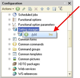
Fig. 106. Creating a settings storage
5.5.12.4. Standard settings storage
The standard settings storage is represented in the 1C:Enterprise language by the StandardSettingsStorageManager object. This object implements the same set of methods as the SettingsStorageManager object, and additionally implements the following methods:
-
Select(). Allows you to process all settings stored in the standard storage. Selection can be filtered. For the settings storage provided by the application, methods for getting the settings list must be implemented manually.
-
GetList(). Method of getting the list of settings for the selected setting object.
-
Delete(). Deletes a specific setting of the selected setting object.
Standard storage saves settings in the system tables of the infobase. The system settings storage takes a string as the key of the settings object and as the settings key. As the settings, the system storage takes any value that can be placed to the value storage.
Note. Note. When using theSave(), Delete() and SetDescription() methods of the StandardSettingsStorageManager object, it must be considered that if the object which the settings are related to (for example, form) has already been used in the current session, the changes will be applied in the next session only.
Note. Tip. In case of a significant programmatic settings change (for example, when copying settings from one user to another), it is recommended that the user be prompted to restart the client application.
5.5.12.5. Saving form settings
The developer can manage saving the form data in the settings. To do this, when developing a form, they need to use the following form properties:
-
Saving form data in settings. Using this property, the form developer can enable the possibility to save form data (with a choice of setting, where the data will be saved to). If the form has requirement to save enabled, the form provides the commands to save/load settings.
-
Automatic data saving in settings. Indicates the requirement to automatically save the settings when closing the form and to restore the settings when opening the form. At this, it does not matter if the list of settings is used.
If the form is set to have data saving possibility, it is necessary to specify which form attributes must be saved (the Saving column on the Attributes tab of the form editor).
When saving settings, the full name of the form is used as the object key. An object of the Map type is saved in the settings, where the paths to the stored attributes are stored as keys, and the attribute values are stored as the values.
5.5.12.6. Saving report settings
The Report and External report objects have the Option storage and Settings storage metadata properties. These properties specify the storages to save the report options and settings to, respectively. If no storages are specified, the storages specified in the configuration properties are used. If the configuration properties also do not indicate specificSettingsStorage objects, the system storage is used.
The report form provides commands for saving and loading report options and settings.
If it is required to save some additional information in the data composition settings or the user data composition settings, AdditionalProperties properties of DataCompositionUserSettings and DataCompositionSettings objects may be used. The AdditionalProperties property is an object of Structure type.
5.5.12.7. Saving dynamic list settings
User dynamic list settings are stored in the storage specified in the configuration properties (DynamicListsUserSettingsStorage). If settings storage is not specified in the configuration properties, the system storage is used.
The possibility to automatically save user dynamic list settings is controlled by the Automatically save user settings property of a form attribute of DynamicList type. When the property is set to True, user settings are automatically saved when the form is closed and loaded when it is opened.
The dynamic list form provides commands for saving and loading user settings. The dynamic list also provides a command for setting default settings. When this command is executed, the settings that are in the List.SettingsComposer.Settings property will be applied to the dynamic list.
For a dynamic list, it is possible to invoke the OnUpdateUserSettingSetAtServer event in the following cases:
-
When opening the dynamic list form.
-
After editing user settings, if the settings components have changed.
5.5.12.8. External URL data
External URL data is stored in the storage specified in configuration properties (URLExternalDataStorage property). If no external data storage is specified in the configuration properties, the system storage is used. In a standard storage, all settings are available for reading for all users.
If the URLExternalDataStorage property is not specified in the configuration, then:
-
In compatibility mode with version 8.3.18 and earlier, a standard storage of URL external data is not created and cannot be manipulated:
-
Calling it from 1C:Enterprise language will cause an error.
-
In report forms and dynamic list forms, you cannot get links with full settings.
-
-
In compatibility mode with version 8.3.19 and later, the platform uses a standard storage as a storage.
The object for which the link is generated is used as the object key in the external URL data storage. String presentation of the generated unique ID is used as the settings key. The same ID is used as the extdata parameter value in the URL.
1C:Enterprise platform does not provide any tools to automatically clear the external URL data storage. Such tools must be implemented at the application level. For example, you can delete all settings starting from a specific date from the storage. Before deleting, check that the settings to be deleted are not used in the user's favorites.
To check the "age" of a storage object, use the StandardSettingsStorageSelection.ChangeDate property. This property contains the date the settings object was recorded.
See also:
-
URLs (see URLs).
-
URL format (see URL formats).
5.5.12.9. Settings storage development procedure
The recommended procedure for developing settings storages is as follows:
-
It is determined, which storage (see the beginning of the section) will be used. For example, the configuration settings form data settings storage will be implemented.
-
The list of metadata objects that will use this storage is determined, and the list of information stored in the storage, its structure and types is identified. This information will help us select the correct metadata object, where our settings will be stored.
-
On the basis of the information from item 2, an object (and its structure) to store the settings is created. Let our settings be stored in the catalog items. Since in our case the structure of the stored data is extremely heterogeneous, there is no sense in implementing a separate set of attributes for storing the settings for each form. Therefore, the settings will be stored in the catalog attribute of ValueStorage type.
-
A SettingsStorage type object is created, and the implementation of the save and load forms is performed for it. This ensures interactivity when saving and restoring settings.
-
For the created SettingsStorage object, event handlers are implemented that are related to saving and restoring settings. If this operation is not performed, then the settings reading/writing operations will not be performed. To solve this problem, it is necessary to implement SaveProcessing and LoadProcessing event handlers in the module of the created SettingsStorage object type.
-
In the objects selected in item 2 (or in the configuration properties), the corresponding properties are filled in, thereby indicating to the objects which storages will contain the settings. In our example, you need to specify a reference to the object created in step 4 in the Form data settings storage configuration property.
-
If necessary, event handlers are implemented which are related to saving and restoring settings in those applied objects where it is required.
5.5.12.10. Operating with settings storage from 1C:Enterprise language
This example illustrates the copying of the current user's settings to other 1C:Enterprise users. SystemSettingsStorage is used as the settings source.
Note. Note. The example below is not complete. It is intended to demonstrate the operation with the standard settings storage.
The username list is passed as a parameter of the CopySettings() procedure as an array.
Procedure CopySettings(UserList)
SettingsDescription
= New SettingsDescription;
SettingsSelection
= SystemSettingsStorage.Select();
While SettingsSelection.Next() Do
For Each User
In UserList Do
SettingsDescription.Presentation
= SettingsSelection.Presentation;
SettingsStorage.Save(SettingsSelection.ObjectKey, SettingsSelection.SettingsKey, SettingsSelection.Settings, SettingsDescription, User);
EndDo;
EndDo;
EndProcedureWhen you access settings, consider one moment. When the standard storage is being processed, settings are deserialized at the moment the StandardSettingsStorageSelection.Settings property is accessed. This means, for example, that if the standard settings storage contains incorrect settings (for any reason), an exception will be thrown not when iterating the settings list, but upon an attempt to access specific settings. Such exception can be caught and incorrect settings can be deleted.
When using the StandardSettingsStorageSelection.Select() method, the resulting selection is sorted in ascending order by the following fields:
-
Hash function value for the string presentation of the User field.
-
ObjectKey field (in alpha-numeric order).
-
Hash function value from the string presentation of the SettingsKey field.
-
Version field.
If native storage of any settings is not created immediately when you start developing an application, the question is how to transfer settings from the standard storage to a newly created storage? The issue is that after creating the settings storage, all accesses through the corresponding global context properties will lead to a new custom storage. To access the standard settings storage after the user storage is created, the platform has a set of methods that returns the standard storage manager of the corresponding settings:
-
GetStandardReportsVariantsStorage(). Standard stogare of report options.
-
GetStandardURLExternalDataStorage(). Standard storage of external URL data.
-
GetStandardFormDataSettingsStorage(). Standard storage of form settings.
-
GetStandardCommonSettingsStorage(). Standard storage of common settings.
-
GetStandardDynamicListsUserSettingsStorage(). Standard storage for dynamic list settings.
-
GetStandardReportsUserSettingsStorage(). Standard storage of custom reports.
Each method returns the standard storage manager, regardless of whether the custom storage is installed or not. So, you can transfer settings between custom and standard storage (in both directions) at any time.
5.5.12.11. Default settings
The standard settings storage can store the so-called default settings. Default settings are system unnamed settings that apply if the current user does not have the same saved setting. The default settings are not supported for named settings, such as custom settings of reports and dynamic lists, form data, and external URL data.
The default settings allow you to pre-configure the application interface without having to copy the settings of a specific user to all existing users of the system. When a new infobase user is created, the default settings allow you to pre-configure the application interface without having to copy the settings of an existing user. The default settings are stored in the system settings storage and this storage cannot be overridden.
When reading the settings for the displayed configuration object, the platform uses the following algorithm:
-
The configuration is used to get the displayed object.
-
The platform tries to read the object settings for the current user.
-
If the current user settings are not found, it tries to read the default settings for this object.
-
If no default settings are found, the object is displayed as configured in Designer.
-
If settings are found in any of the previous steps, these settings are applied and further search is stopped.
-
This algorithm is not applicable from 1C:Enterprise language. In this case, exactly the planned setting will be read.
The Restore default settings user interface command will set the default settings if they are configured for this object. Setting the default settings cancels the current custom settings and deletes them from the storage. If there is a default setting, it is applied. Otherwise, no settings are applied to the object.
For some settings, not new values are saved, but the differences between the previous and new value. These settings include: form settings, client application interface settings, home page settings, and the command interface settings. For these settings, the following behavior will be observed when the corresponding settings editor is closed:
-
If the custom settings match the default settings, the custom settings are not written to the storage. If there are already custom settings in the storage, they are deleted.
-
If the custom settings differ from the default settings, the user settings are written to the storage.
To save the default settings, the user on whose behalf the settings are saved needs the DataAdministration access right. After the default settings for a form (form settings) are saved in the current session, the saved settings begin to take effect in another user's session no later than 20 seconds after saving, if the user does not have their own settings for this form.
The interface for default settings is similar to the interface for regular settings, down to the method names. To access the methods, use the standard settings storage manager (the SystemSettingsStorage global context property):
-
To save the default settings, use the SaveDefaultSetting() method.
-
To read the default settings, use the LoadDefaultSetting() method.
-
To iterate through the default settings, use the SelectDefaultSettings() method.
-
To delete the default settings, use the DeleteDefaultSetting() method.
A specific setting in the above methods is identified by specifying the object key or filter item.
5.5.13. Common forms
The common form functionality allows you to use forms available from any module of the current configuration.For details on how to work with the form editor, seeForm editor.
If it is necessary to place the command for opening a common form in the command interface, this can be done using Use standard commands property. The command for opening a common form will be placed in the command interface of those subsystems which the common form belongs to. If the common form is included in the functional option and the functional option is disabled, the standard common form command is not displayed in the command interface.
If a common form is created, which will be used as a form of report, report settings or option, it is not recommended to set Use standard commands property for such form.
5.5.14. Common commands
In this branch, the developer can create commands that do not have object specificity or serve to perform actions with objects that do not use standard commands.
For the command interface details, seeCommand interface. For the command details, see Commands.
5.5.15. Command groups
In this branch, the developer can create their own command groups. The created group will be located in the section of the command interface that is defined by the Category command property. A command group can be placed in:
-
Navigation panel
-
Form navigation panel
-
Actions panel
-
Form command bar
5.5.16. Common templates
The common template functionality (print forms, report forms, reference data, and so on) allows creating print form templates that are available from any module of the current configuration.
For details on how to work with the spreadsheet document editor, see Spreadsheet document editor.
5.5.17. Common pictures
5.5.17.1. General information
Designer allows you to include graphic pictures, or images, in the configuration. Images can be placed in certain controls, forms, templates, and can also be accessed using the 1C:Enterprise language.
The application can run on devices with different screens in terms of their size, resolution, and point density. Point density is characterized by the dpi (or ppi) concept, that is the number of pixels per inch of the screen size. The higher the dpi value, the less physical space will be occupied by the image with fixed physical dimensions. In addition, the image may be displayed in a form for which a scale is indicated, that is, the format may be larger or smaller than its base size.
To better adapt a picture to different screens, you can specify it as a set, where each picture corresponds to a certain dpi interval of the mobile device screen. In this case, the platform automatically picks the desired image (from the set), based on the parameters of a particular physical device. The application programmer must not take any actions to display the desired image.
A set of images is a zip-format archive that contains images, which are described in the manifest file (manifest.xml) located in the same archive (for details, see Image manifest). The image may refer to one of the screen resolution options:
-
bldpi: scale 85%.
-
lpdi: scale 100%. For mobile devices: resolution of at least 140 dpi.
-
aldpi: scale 125%.
-
mdpi: scale 150%. For mobile devices: resolution 140 to 180 dpi.
-
amdpi: scale 175%.
-
hdpi: scale 200%. For mobile devices: resolution 180 to 270 dpi.
-
xdpi: scale 300%. For mobile devices: resolution over 270 dpi.
-
udpi: scale 400%.
The name of each image can be arbitrary, and the ratio between the name of the image and the resolution is specified in the manifest. The ratio of the image size in the archive can be calculated based on the image size for the scale of 100%. Thus, if at a scale of 100% the size of a image is 16 pixels, then the following set of image sizes for different display scales can be obtained:
-
bldpi: 16*0.85 = 14 dots
-
ldpi: 16*1.00 = 16 dots
-
aldpi: 16*1.25 = 20 dots
-
mdpi: 16*1.50 = 24 dots
-
amdpi: 16*1.75 = 28 dots
-
hdpi: 16*2.00 = 32 dots
-
xdpi: 16*3.00 = 48 dots
-
udpi: 16*4.00 = 64 dots
The archive can also contain so-called template pictures. These are the images, the informative part of which is present only in the alpha channel of the RGBA model. The values of the remaining channels in such image must form a white color (R=255, G=255, B=255). Template image is recommended to be generated in PNG format (32 bits per pixel). When displaying such image, the field allocated for the image will be filled with the current background color, and the text color (with relevant intensity) will display those areas of the image for which the alpha channel has values different from full transparency (A=0).
A set of pictures must contain a picture for ldpi resolution kind (basic picture). The other images are optional. If the desired image it not found, 1C:Enterprise will use the image whose parameters are as close to the desired ones as possible.
If you plan to use an image as an icon in a menu, a tools panel, a spreadsheet document, and other, set the correct size for it so that it is displayed without distortion.
Recommended image size for 100% display scale:
-
For icons not more than 16x16 pixels.
-
For tabular field, not more than 14x14 pixels.
-
As the editing field selection button, not more than 9x9 pixels.
-
For the image to be used as subsystem presentation, not more than 48x48 pixels.
Note. Tip. If the image is planned to be used in several places, it is reasonable to limit its size to a smaller value.
5.5.17.2. Configuration picture library management
The Image Library window is intended for operations with the images. To call it, specify the Common images branch in the Configuration window and select All images item from the context menu.
A window with a list of pictures will appear on the screen:
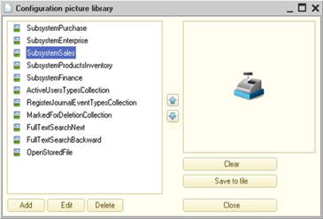
Fig. 107. Picture library
To add a new image, click Add. This opens a dialog box with properties of the new common picture (see Common picture properties). The dialog box for editing the new common picture will be filled with default values and an empty picture.
To open a dialog box with properties of the existing common picture, click Edit. To remove the selected common picture from the picture library, click Remove.
You can preview the current common picture on the right of the library window. To change the order of common pictures, you can use the up and down arrow buttons between the list of pictures and the preview field.
Below the common picture preview field, you will find the following buttons:
-
Clear. Clears the current picture.
-
Save to file. Saves the current common picture to a file on a hard drive.
5.5.17.3. Common picture properties
The common picture has a set of properties and actions that you can perform with this picture. To identify the common picture, use the Name property. This name will be used in 1C:Enterprise language if you use the PictureLib global-context property.
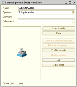
Fig. 108. Picture properties
You can import a ready-to-use picture from a file by clicking Select from file. If you select an SVG picture with animation, you will be prompted to convert this picture (see Item images). You can draw a picture directly in Designer. To do it, click Edit (for details, see Image editor). Clicking Clear will clear the current picture, and the Save to file button will save the current common picture to a file on a hard drive. The type of the current picture is displayed in the Picture type field at the bottom of the common picture properties window.
The following picture formats are supported in 1C:Enterprise: BMP, GIF, JPEG, PNG, TIFF, ICO, SVG, as well as metafiles (WMF, EMF) and picture sets in a ZIP archive (for more information, see below).For images in theGIF format, the supported extensions are NETSCAPE2.0, ANIMEXTS1.0, and XMP DataXMP. Other extensions are not supported and the 1C:Enterprise behavior in this case is not defined.
The following items are ignored for SVG images:
-
JavaScript and any interactivity, including CSS properties associated with interactivity, for example, pseudo-class :hover. When you receive an SVG picture from an infobase, temporary storage, or via a direct link, the client application removes those picture items that may contain JavaScript text.
-
Style properties:
-
color-interpolation
-
color-rendering
-
-
Zero-length path markers
-
feTile primitive filter
-
Elements of embedded fonts:
-
font
-
altGlyph
-
altGlyphDef
-
altGlyphItem
-
glyphRef
-
-
enable-background property
-
References to external resources
-
The image element does not support the relative path to the image file.
Note. Tip. For pictures that will be used as interface icons (for recommended picture sizes, see General information), use formats that support lossless compression (PNG and GIF) to avoid distortion and minimize traffic between the client and the server.
The Available for selection property allows you to specify that this picture can be selected when editing a picture in a cell, figure, or spreadsheet document header in 1C:Enterprise mode.
The Available for appearance property allows you to specify that this picture can be used when editing the conditional appearance of reports in 1C:Enterprise mode.
To make the picture fit better into the control or form, you can set a transparent background for the picture. To do this, just select any color that is not used in the picture as the background color when editing an image, create an image and save it. For an existing image, any color can be specified. Due to the established transparency of a given color, details of that section of the form that covers the area of the image become visible through it. You can set a transparent background only for BMP, JPEG, and TIFF pictures. For images in other formats, these buttons are unavailable.
To set a transparent background, click the Set transparent background button. The mouse pointer will change its appearance. Place the pointer on the image section, that you want to make transparent, and click the left mouse button. The selected color becomes transparent. To remove transparency, click the Clear transparency button.
TheEnable option set and Disable option set buttons allow you to work with pictures united in a specially designed archive containing several pictures, where each picture is drawn for its own scale option (for details, see General information). If you click Enable option set, the current picture is converted to the option set format and becomes the basic picture (for ldpi resolution).
Clicking the Disable set of options button causes all images to be deleted from the image set except the base image (the image for ldpi resolution). If there is no image for ldpi resolution in the set, the set becomes empty. If the set contains an image for ldpi resolution, and it is set as an outline, then the template flag is reset.
If a picture is an option set, then clicking Edit in the picture properties dialog box will not open the editor of this particular picture. Instead, this will open a dialog box for editing the whole picture set.
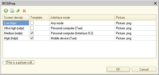
Fig. 109. Editing a set of images
The dialog box for editing a picture set is a table where each set picture is described in a separate row. Let us consider properties of an individual picture in more detail:
-
Screen density. Indicates the screen resolution this picture is intended for. For a list of supported resolutions, see General information.
-
Template. This checkbox indicates that the picture is a template one (see General information). Use this checkbox to design mobile device interfaces.
-
Direction. This property describes how the picture will be displayed in the interface with different text view options. In this property, the developer specifies how the picture will be used by the platform to function in different modes of text input and view.
-
Any. The picture will be displayed "as is" in any interface mode. Use it for pictures to be displayed in the same way in all interface modes (LTR or RTL).
-
Left to right, can be mirrored:
-
In LTR interface, the picture is displayed "as is".
-
In RTL interface, the picture is mirrored.
-
Specify this value for a picture that was originally drawn for LTR interface, but mirroring will make it suitable for RTL interface.
-
-
Right to left, can be mirrored:
-
In LTR interface, the picture is mirrored.
-
In RTL interface, the picture is displayed "as is".
-
Specify this value for a picture that was originally drawn for RTL interface, but mirroring will make it suitable for LTR interface.
-
-
Left to right:
-
In LTR interface, this picture variant is preferred.
-
In RTL interface, it is displayed "as is".
-
Specify this value for a picture that is drawn for LTR interface and cannot be modified for display.
-
-
Right to left:
-
In LTR interface, the picture is displayed "as is".
-
In RTL interface, this picture variant is preferred.
-
Specify this value for a picture that is drawn for RTL interface and cannot be modified for display.
-
-
If a picture can and must be mirrored, the platform mirrors the picture automatically.
If a picture has different variants with different directions, the required picture variant is selected as follows:
-
Priority of picture variants in LTR interface (in descending order):
-
Left to right
-
Left to right, can be mirrored
-
Right to left, can be mirrored
-
Any
-
Right to left
-
-
Priority of picture variants in RTL interface (in descending order):
-
Right to left
-
Right to left, can be mirrored
-
Left to right, can be mirrored
-
Any
-
Left to right
-
-
Interface. This column indicates the interface where this picture will be used:
-
taxi. Taxi interface.
-
taxiCompact. Taxi interface with compact display option. This option is only available when manually editing the manifest.
-
taxiMobile. The Taxi interface for mobile applications.
-
version8_2. Version 8.2 interface.
-
version8_2_OrdinaryApp. Ordinary application interface. This option is only available when manually editing the manifest.
-
version8_0. Interface for 1C:Enterprise version 8.0 and 8.1 configurations. This option is only available when manually editing the manifest.
-
-
Web browser (for web client). Defines the browser where the current picture will be displayed in web client. If this property differs from the Any value, then in web client in the selected web browser, the picture that is marked for display in this web browser will be displayed. The main purpose of this property is to display SVG pictures with animation (see Item images).
-
Picture. This property displays the actual picture. To edit the variant picture, start editing the Picture cell, and click the "..." selection button in the edit field. This will open the picture editing dialog box (see Image editor).
-
You can edit picture collections using the Collection mode checkbox, which is located under the table with the picture list, and the Cell width and Cell height columns. For more information on the picture collection, see Image collections.
You can set collection parameters (width and height of the collection cell) both in the variant editing dialog box and in the picture editing dialog box. Changing the collection parameters does not automatically change collection items. The picture editor will just split the picture into items in a different way. To modify the size of a collection item, go to the editor, change the collection parameters, change the view of all pictures, and save the changes.
If the Collection mode checkbox is cleared, the picture set dialog box will look as follows:
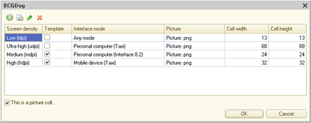
Fig. 110. Editing a set of images (without collection)
If an image for any resolution is not set, the input field corresponding to the image will be blank. Moreover, the fields describing cell width and height in the collection mode will be empty as well. If no picture is specified, you will see the result as:
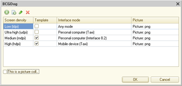
Fig. 111. Variant without a picture
Clicking … button in the corresponding image set editing dialog box will open the image selection dialog box. Pressing X button will clear the corresponding image of the dialog box. You can also clear the variant picture by clicking Clear in the dialog box for editing a variant picture. Editing an individual image of a set does not differ from editing an individual image.
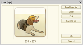
Fig. 112. Editing one option picture
If you are editing a picture from a variant that is a collection, consider the following values: the Cell width and Cell height picture properties in the picture set editor, numbers at the bottom of the picture preview field, properties of the picture itself (fig. 112), and the Cell width and Cell height properties of the Collection parameters group of the Picture parameters picture editor. For a collection to be displayed correctly, the following conditions must be met:
-
The Cell width and Cell height properties in the variant editor and in the picture editor dialog box describe the same value, are linked to each other, and match.
-
Digits in A x B format specified at the bottom of the picture preview field (fig. 112) must be linked with the collection cell parameters as follows:
-
Cell width * Number of pictures in collection must match the first expression digit.
-
Cell height must exactly match the last expression digit.
-
For example, in fig. 112, the expression is 918 x 51. This means that the picture contains 18 collection items with a cell size of 51 by 51 pixels.
-
If you place an arbitrary size picture in a collection and specify a certain collection size, 1C:Enterprise will create collection items by editing the specified picture starting from the upper left corner according to the specified collection parameters.
5.5.17.4. Image manifest
If an image contains a set of options, such image must be represented by an archive containing the packed actual image files and the manifest file (manifest.xml), which describes which images are prepared for which scale options in this archive.
Manifest (manifest.xml) must correspond to the following scheme:
<xs:complexType
name="PictureVariant">
<xs:sequence>
</xs:sequence>
<xs:attribute
name="name" type="xs:Name" use="required"/>
<xs:attribute
name="screenDensity" type="tns:PictureVariantScreenDensity"
use="required"/>
<xs:attribute
name="isTemplate" type="xs:boolean"
default="false"/>
<xs:attribute
name="interfaceVariant"
type="tns:PictureInterfaceVariant"/>
<xs:attribute
name="glyphWidth" type=xs:decimal" />
<xs:attribute
name="glyphHeight" type=xs:decimal" />
<xs:attribute
name="direction" type=xs:PictureDirectionVariant" />
<xs:attribute
name="webBrowser" type=tns:WebBrowser" />
</xs:complexType>
<xs:simpleType
name="PictureVariantScreenDensity">
<xs:restriction
base="xs:string">
<xs:enumeration
value="bldpi"/>
<xs:enumeration
value="ldpi"/>
<xs:enumeration
value="aldpi"/>
<xs:enumeration
value="mdpi"/>
<xs:enumeration
value="amdpi"/>
<xs:enumeration
value="hdpi"/>
<xs:enumeration
value="xdpi"/>
<xs:enumeration
value="udpi"/>
</xs:restriction>
</xs:simpleType>
<xs:simpleType
name="PictureInterfaceVariant">
<xs:restriction
base="xs:string">
<xs:enumeration
value="taxi"/>
<xs:enumeration
value="taxiCompact"/>
<xs:enumeration
value="version8_2"/>
<xs:enumeration
value="version8_2_OrdinaryApp"/>
<xs:enumeration
value="version8_0"/>
<xs:enumeration
value="taxiMobile"/>
</xs:restriction>
</xs:simpleType>
<xs:simpleType
name="PictureDirectionVariant">
<xs:restriction
base="xs:string">
<xs:enumeration
value="rtlCanFlipHorizontally"/>
<xs:enumeration
value="ltrCanFlipHorizontally"/>
<xs:enumeration
value="ltr"/>
<xs:enumeration
value="rtl"/>
</xs:restriction>
</xs:simpleType>
<xs:simpleType name="WebBrowser">
<xs:restriction
base="xs:string">
<xs:enumeration
value="MicrosoftInternetExplorerMicrosoftEdgeHTML"/>
</xs:restriction>
</xs:simpleType>screenDensity attribute specifies, which display scale this image will be used for.
The interfaceVariant attribute specifies the interface variant the picture is intended for. If the attribute is not specified, the interface is displayed as Any in the variant editing dialog box.
The glyphWidth and glyphHeight attributes describe the size of the collection item for the image specified in the item. These values will be further passed to the image editor, which splits the image into a collection using them.
The PictureDirectionVariant attribute specifies how the picture must be displayed in interfaces with different text display modes (LTR or RTL). If the attribute is not specified, the direction is displayed as Any in the variant editing dialog box. Attribute values in relation to displayed values:
-
rtlCanFlipHorizontally: Right to left, can be mirrored.
-
rtlCanFlipHorizontally: Left to right, can be mirrored.
-
ltr: Left to right.
-
rtl: Right to left.
5.5.18. XDTO packages
The XDTO functionality is a versatile way of presenting data for interacting with various external data sources and software systems.
5.5.18.1. Importing XML schema to global XDTO factory
To import the XML schema from the .xsd file to the XDTO global factory, select the XDTO branch in the configuration tree and execute the Import XML Schema... context menu command.
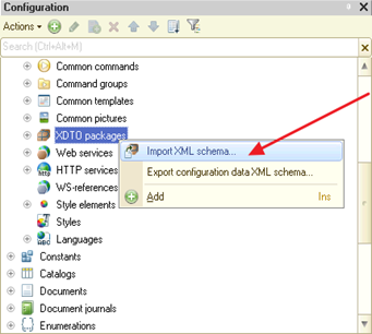
Fig. 113. Importing XML schema
After specifying the required .xsd file, the existence of the XDTO package in the configuration tree will be checked, which namespaces are the same as those imported from the file. If such packages exist, a list of these packages will be displayed and the user will be prompted to specify those packages that must be updated (existing packages are not updated by default).
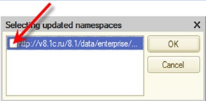
Fig. 114. Namespace selection
When importing XML schema (XSD) in the XDTO package, it is necessary to ensure correct dereference of all the schemas specified in the import and include directives (import, include) transitive closure. To do this, the import and include directives (import, include) must contain a schemaLocation attribute containing the address (or path) of the imported or included schema.
After that, the import will be performed, as a result of which new XDTO packages will be added to the configuration tree, and packages marked for updating will be updated.
5.5.18.2. Exporting configuration XML data schema
To export an XML schema corresponding to the configuration data types (excluding XDTO packages created in the configuration tree) to .xsd file, select the XDTO branch in the configuration tree and execute the Export XML schema of configuration data… context menu command.
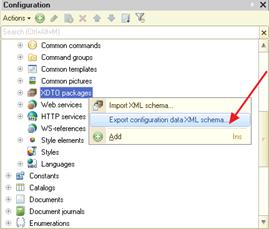
Fig. 115. Exporting configuration schema
After selecting a directory and specifying a file name, the XML schema will be exported to the specified file.
5.5.18.3. Exporting XDTO package XML schema
To export an XML schema corresponding to an existing XDTO package to .xsd file, select the required XDTO package in the configuration tree and execute the Export XML schema… context menu command.
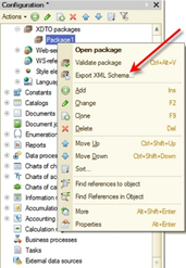
Fig. 116. Exporting XDTO package XML schema
After that, the XDTO package being exported will be checked. If errors are found, the corresponding messages will be displayed in the message window, and the export procedure will be interrupted.
In case of successful verification, user will be prompted to select the directory and the name of the .xsd file, after which the XML schema will be exported to the specified file.
5.5.18.4. Checking XDTO packages
In order to check the XDTO package, select the required XDTO package in the configuration tree and execute the Verify package command from the context menu.
As a result, the XDTO package model will be verified (for a description of the verification rules, see XDTO ).
If errors are found, the corresponding messages will be displayed in the message window.
5.5.18.5. XDTO package editing window
5.5.18.5.1. General information
The XDTO package editing is performed in the XDTO package editing window.
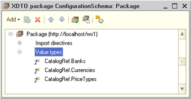
Fig. 117. XDTO package editing window
When a new XDTO package is added to the configuration tree, the XDTO package editing window opens automatically.
In order to open the editing window for the existing XDTO package, select the required XDTO package in the configuration tree and execute the Open package command from the context menu.
5.5.18.5.2. XDTO package hierarchical structure
The XDTO package editing window contains the hierarchical structure of the XDTO package, displayed as a tree.
XDTO package ID containing the namespace URI of this package is located at the root of the tree.
At the first level of the hierarchy the following package items can be located:
-
Import directives. List of import directives. Each import directive is a link to another package containing the types that this package refers to in one or another way. When working with this XDTO package using the 1C:Enterprise language, this list of import directives will be available as an XDTOPackageCollection object contained in the Dependencies property of XDTO package.
-
Value types. List of XDTO value types, which are included in XDTO package.
-
Object types. List of XDTO objects, contained in XDTO package.
-
Properties. List of XDTO package properties. Represents objects/values declarations that may be the root elements of XML documents belonging to the namespace URI of this XDTO package.
-
Each XDTO value type is described by a hierarchical structure and may contain the following items:
-
Pattern describes one XDTO facet of Pattern type.
-
Enumeration describes one XDTO facet of the Enumeration type.
-
Each XDTO object type is described by a hierarchical structure and may contain the object property set.
5.5.18.5.3. XDTO package properties
The XDTO package properties are edited in the property palette.
If the property palette is open for the XDTO package selected in the configuration tree, it will contain the following properties: Name, Synonym, Comment, and Namespace URI. In addition, the property palette will contain the Package reference, which can be used to go to the XDTO package editing window.
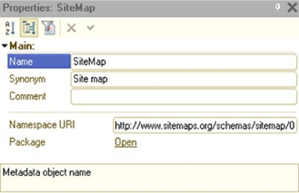
Fig. 118. XDTO package properties
If the property palette is open for the XDTO package selected in the XDTO package editing window (root element), it contains the only the Namespace URI property. This property specifies the XDTO package namespace URI, which all the types defined in this package belong to.
5.5.18.5.4. Import directive properties
The import directive properties are edited in the property palette. For the import directive, the property palette contains the only the Namespace property. This property specifies the imported package namespace URI.
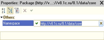
Fig. 119. Import directive properties
5.5.18.5.5. XDTO value type properties
The XDTO value type properties are edited in the property palette.
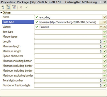
Fig. 120. XDTO value properties
For the XDTO value type, the property palette contains the following properties:
-
Name. XDTO value type name.
-
Base type. Base type for this XDTO value type.
-
Option. Simple type option (atomic type, list, combination). If the value is set, it must be consistent with the Item type and the Merge types values.
-
Item type. List item type when XDTO value type is determined by a list. In this case all the facets and Subordinate types property must be empty.
-
Merge types. List of types that constitute the merging if the XDTO value type is determined by the merging. Only XDTO value types can be merged. In this case all the facets and Item type property must be empty.
-
Length. Length facet.
-
Minimum length. Minimum length facet.
-
Maximum length. Maximum length facet.
-
Space characters. Whitespace character facet.
-
Minimum, including border. Facet of minimum, including the border.
-
Minimum, not including border. Facet of minimum, not including the border.
-
Maximum, including border. Facet of maximum, including the border.
-
Maximum, not including border. Facet of maximum, not including the border.
-
Total number of digits. Facet of the total number of digits.
-
Number of decimals. Facet of the number of decimal digits.
5.5.18.5.6. XDTO object type properties
The XDTO object type properties are edited in the property palette.
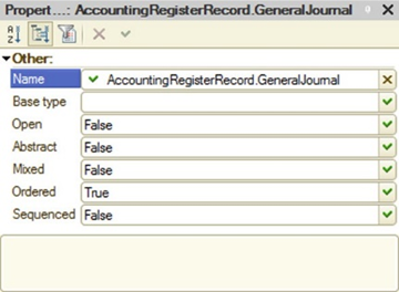
Fig. 121. XDTO object properties
For the XDTO object type, the property palette contains the following properties:
-
Name. XDTO object type name.
-
Base type. Base type for this XDTO object type. This may be an XDTO object type only.
-
Open. Indicates whether the XDTO object type is open. This property indicates whether an instance of an XDTO object can contain additional properties that are not defined in its type.
-
Abstract. Indicates whether the XDTO object type is abstract.
-
Mixed. Indicates whether the corresponding XDTO object has mixed contents. If the Mixed property is True, then the Serial value must be True, since the mixed content cannot be modeled without using the XDTO sequence.
-
Ordered. Indicates whether the sequence of the items representing property values is strictly the order with the XDTO object type properties. If the Ordered property is False, then the sequence of the XML items is not controlled at the input, and at the output it is determined by the sequence of the properties, unless the Serial property is True.
-
Sequenced. Indicates whether the instance of the respective XDTO object contains the XDTO sequence. This flag is True in those cases where the following order of the nested XML items cannot be determined unambiguously by the sequence of the properties in the type or the corresponding XDTO object has mixed content. The XDTO sequence allows you to explicitly define the sequence of the items as they appear in the XML document. For objects of types where the Serial property is False, the sequence of nested elements corresponds to the sequence of properties.
5.5.18.5.7. Properties of XDTO object type properties
The properties of XDTO object type properties are edited in the property palette.
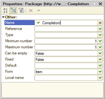
Fig. 122. XDTO type property palette
For the XDTO object type, the property palette contains the following properties:
-
Name. Property name. Within the XDTO object of the same type, property names must be unique.
-
Type. Property type. It can be either the XDTO value type, or the XDTO object type.
-
Minimum quantity. Minimum quantity of the property values. The minimum quantity of property values can be >= 0. Naturally, the Minimum quantity value must be less than or equal to the Maximum quantity value (unless, of course, the Maximum quantity is 1).
-
Maximum quantity. A property of an XDTO object type can be defined as containing one or many values. A property is considered to contain one value if the Maximum quantity property is 1. If the Maximum quantity property is bigger than 1, then it is considered that the property may contain multiple values. Such a property is modeled as a list in the object structure. The Maximum quantity property indicates the maximum quantity of the property values. The maximum quantity > 1 can be set only for properties that are represented as an XML item.
-
Possibly empty. Indicates whether the property can have an undefined value. Possibly empty property, when it is True, can only be defined for properties with the Item presentation form. If the Maximum quantity is > 1, the undefined value is valid for the property values list item.
-
Fixed. Indicates whether the property value is fixed. If set to True, the fixed value itself can be retrieved through the Default property.
-
Default. Default property value. The default value type can only be the XDTO value type. At the same time, this value must be compatible with the property type (to be of the same type as the type of the property or of the inherited type). When creating an XDTO object, the property, if it permits a single value, is assigned the default value. For properties with multiple values, the list of values is initially empty, regardless of whether the default value is defined or not.
-
Form. Property presentation form in XML. This can be Text, Item, or Attribute. If the presentation form is Attribute or Text, the value of the Maximum quantity property cannot exceed 1. If the property is set to Text, then the value of the Minimum quantity property must also be 1. One type contains only one property that can have the Text presentation form. The other properties must have the Attribute presentation form.
-
Local name. Local name used to represent the property. For properties with the Text presentation form, it is an empty string.
5.5.18.5.8. Global property
The properties of the global property are edited in the property palette.
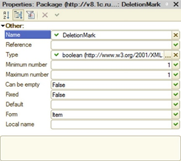
Fig. 123. Property palette of the global property
For the global property, the property palette contains the following properties:
-
Name. Global property name. Within the XDTO object of the same type, global property names must be unique.
-
Reference. Reference to the package property root definition.
-
Type. Global property type.
-
Minimum quantity. Minimum quantity of the property values. If the Minimum quantity = 0, the property value may be not set.
-
Maximum quantity. Maximum quantity of the property values. If Maximum quantity is 1, the quantity of property values is not limited.
-
Possibly empty. Indicates whether the property can have an undefined value.
-
Fixed. Indicates whether the property value is fixed.
-
Default. Default property value. The lexical presentation of the property value must follow the rules for checking this property type.
-
Form. Property presentation form in XML. This can be Text, Item, or Attribute.
-
Local name. Local name used to represent the property.
5.5.19. Web services
The web services functionality allows using 1C:Enterprise as a set of services in complex distributed and heterogeneous systems. Also, it allows you to integrate 1C:Enterprise with other industrial systems using a service-oriented architecture.
For more information on using the Web services feature, see Web services.
5.5.19.1. Adding web services
To add a web service to the configuration tree, select the Common – Web services branch and execute the Add context menu command.
As a result of the command execution, the web service editing window will open (see Object editing window).
In the Miscellaneous tab of the web service editing window, set the following parameters:
-
Namespace URI. Contains web service namespace URI. Each web service can be uniquely identified by its name and the URI of the namespace to which it belongs.
-
XDTO packages. List of XDTO packages whose types can be used as return value types for web service operations and operation parameter types.
-
Publication file name. Name of the web service description file located on the web server.
To access the web service, use an address generated as follows: <Web server host name>/<Virtual directory name>/ws/<Web service name> or <Web server host name>/<Virtual directory name>/ws/<Web service address>.
For example, the virtual directory name is DemoWS, the web service name in Designer is OperationDemoWS, and the address is DemoWorkWS. In this case, you can access the web service via any of the following addresses (to get access from a local computer): http://localhost/DemoWS/ws/OperationDemoWS or http://localhost/DemoWS/ws/DemoWorkWS.interface
In addition, the tab contains the Module button. You can click it to open the web service module for editing.
5.5.19.2. Hierarchical web service structure
Each web service described in the configuration tree can contain a set of operations. Each operation must correspond to the exported procedure described in the web service module.
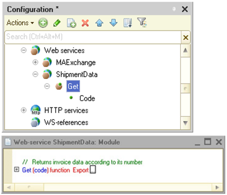
Fig. 124. Web service description
In turn, each operation may contain a set of parameters, the names of which must correspond to the parameter names of the procedure that describes this operation.
5.5.19.3. Web service operations
Web service operation is added in the Operations tab. The operation properties are edited in the property palette.
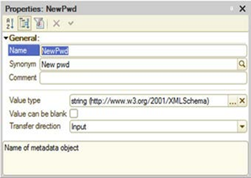
Fig. 125. Web service operation property
Return value type. Type of the value returned by the web service operation. It may be either an XDTO value type or an XDTO object type.
Possibly empty value indicates whether the return value can be undefined.
In transaction. Indicates whether the web service module code will be executed in a transaction. If the property is set, then when the Web service is called, the transaction will be automatically started, and upon completion, the transaction will either be docked or rolled back (depending on the results of the execution). If the property is not set, the transaction will not start when the web service module execution starts.
Method name. Name of the web service module procedure that will be executed when this property is called.
Data lock management mode indicates which locks will be used when accessing the data (for details, see Data operations).
5.5.19.4. Operation parameters
On the Operations tab for the specified operation, it is necessary to set the parameters for the web service operation. The parameter properties are edited in the property palette.
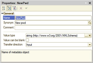
Fig. 126. Operation parameter properties
Value type. Value type of the web service operation parameter. It may be either an XDTO value type or an XDTO object type.
Possibly empty value indicates whether the operation parameter value can be undefined.
Transfer direction determines the data transfer direction using this parameter. Values:
-
Input. Means that the parameter can only be used to transfer data to the web service.
-
Output. Means that the parameter can only be used to retrieve data from the web service.
-
Input – Output. Means that the parameter can be used both to transfer data and get to/from the web service.
5.5.19.5. Specifying system type collections
In order to use the types defined by the 1C:Enterprise in the web service (for example, in the parameters and return value of the operations), it is necessary to define the XDTO packages in the configuration and for each package specify the platform packages set, which include these types, in its list of imported packages (Import directives property). The namespace URI for specifying the type is contained in the article of the Syntax Assistant for an object of this type.
5.5.20. HTTP services
The HTTP services functionality allows using 1C:Enterprise as a set of services in complex distributed and heterogeneous systems, and also allows integrating 1C:Enterprise with the other industrial systems.
For details on using HTTP services, see Creating your own HTTP service.
For details on editing HTTP services, see Developing HTTP services.
5.5.21. WS references
The 1C:Enterprise can use web services provided by the third parties using static links created in the configuration tree.
5.5.21.1. Adding WS reference
In order to add a static link to an external web service to the configuration tree, select the WS references branch and execute the Add context menu command or the corresponding Actions menu command.
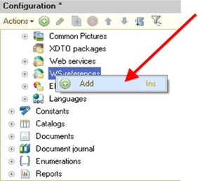
Fig. 127. Adding WS reference
In the opened window, enter the description URL of the web service to be added, for example: https://platform.demo.1c.ru/wsdemo/ws/products.1cws?wsdl.
Note. Note. When adding a WS reference, remember that 1C:Enterprise the trailing character "/" from the entered URL, due to which the URL http://localhost/ws/ws-service/?wsdl and URL http://localhost/ws/ws-service?wsdl in terms of 1C:Enterprise will be considered identical.
5.5.21.2. Hierarchical WS reference structure
You can view the hierarchical WS reference structure in the WS reference view window. The reference element property values can be viewed in the property palette.
In order to open the WS reference viewer window, select the required WS reference in the configuration tree and execute the Properties context menu command. After that, in the property palette, use the WS reference link, which opens a window for viewing WS reference.
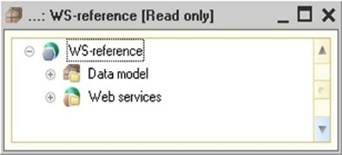
Fig. 128. WS reference
The view window contains the hierarchical WS reference structure displayed as a tree.
The following items can be located at the first level of hierarchy:
-
Data model contains a list of XDTO packages describing the type structure used by web services referenced by this WS reference.
-
Web services is a list of web services referenced by this reference.
The structure and properties of the data model are viewed in the same way as when working with XDTO packages (see XDTO ), except for the fact that editing the package properties displayed in the WS reference viewer window is impossible.
The WS reference structure is viewed in the same way as when working with web services, except for the fact that for each web service, supported web service connection points are displayed, for which, in turn, a list of operations and parameters of each operation is displayed.
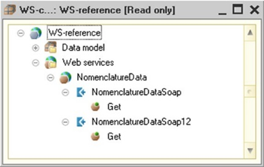
Fig. 129. Web service structure
Various web service connection points allow executing the operations using different protocols.
5.5.22. Styles and style elements
Style is a collection of various settings used for the user interface design. Using the style, you can quickly change or set the desired design. Style includes a specific set of system style elements and an arbitrary number of user style elements. The main configuration style is set using the Main style configuration property. It is also possible to perform a programmatic style setting using the MainStyle global context property. This property is writable only in the SessionParametersSetting event handler. Reading this property is possible at any time.
The following elements are the system style elements (indicating the areas of application of each style element):
-
Activity color (ActivityColor). This color displays:
-
Client application for personal computer:
-
Current form element border.
-
Current menu item background.
-
Current table row and cell background.
-
-
Mobile client:
-
Current menu item background.
-
Current table row and cell background.
-
Form title background.
-
Indicator color.
-
Desktop pictures color.
-
Is used for the formation of the form table line context menu button background.
-
-
-
Accent color (AccentColor). This color displays:
-
Client application for personal computer:
-
Group title text.
-
Checkbox, switch and strip control.
-
Indicator of the current form in the open panel.
-
Image of the notification center on the toolbar (if there are new notifications).
-
-
Mobile client:
-
Selected page title text color.
-
Checkbox, switch and strip control.
-
Buttons color.
-
Only in case of operation in Android OS:
-
Band color in the input field in the edit mode.
-
Color of the bands on the spin-wheel date picker.
-
-
-
-
Navigation color (NavigationColor). This color displays:
-
Client application for personal computer:
- Sections panel background.
-
Mobile client:
- Unused.
-
-
Additional navigation color (AuxiliaryNavigationColor). This color displays:
-
Client application for personal computer:
- Current section functions panel background.
-
Mobile client:
- Unused.
-
-
Important color (ImportantColor). This color displays:
-
Client application for personal computer:
- Default button background.
-
Mobile client:
- Unused.
-
Setting up any other system elements of Taxi interface, except those listed above, is not supported. However, it is possible to use other system style elements for designing form elements. They will contain effective color combinations, but cannot be changed.
The configuration style editor has the following appearance:
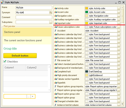
Fig. 130. Style editor
Above the red dividing line (in the figure) system style elements are shown, below are the user style elements. If a style element does not have any value in the editor of a particular style, then the value specified in the style element itself will be selected as the value of this element in this style. Thus, for example, in MyStyle style (fig. 130) for Accident style element no specific color value is specified. Therefore, for all the elements, using the Accident color of MyStyle style the color, which is specified directly in the Accident style element, will be used.
Style elements configuration objects are intended for uniform design of various form elements in cases where the design that is automatically offered by 1C:Enterprise is not sufficient. For example, it is required to make the color of any labels in configuration forms the same. In this case, it is reasonable to create a style element, set a color for it and use the created element to set the form element text color.
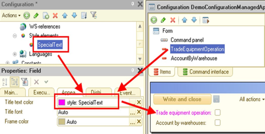
Fig. 131. Style element usage
Style elements can be of three various types:
-
Color
-
Font
-
Border
Note. Note. The names of the system style elements are not available for selection as user style elements values.
In the font selection dialog box in the thin client, the list of fonts contains fonts installed on the current computer and a list of special fonts enclosed in angle brackets (<>). If the <Text font> font is selected, then the 1C:Enterprise interface font will be used, the other fonts correspond to the respective operating system fonts. The <> element exists in the beginning of the <Text font> font size list. The choice of this font size (its value is 0) means that the font size of the 1C:Enterprise interface will be used. The font style (bold, italic, and other) is taken from the style by default but can be changed by the user without any restrictions. When another font is selected, user changes of size or style are not saved and are set to default values.
It is possible to programmatically access the value of a style element using the Value property.
Example:
Metadata.StyleItems.ColorOfNegative.Value5.5.23. Languages
Languages configuration objects are intended to create a program interface in different languages. For each configuration object of the Languages type, a separate row is reserved for those metadata attributes that can be presented in different languages.
Consider an example of the form for Products catalog item. For the Russian language the form labels are as follows:
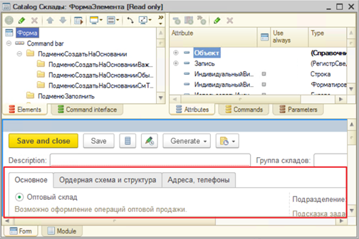
Fig. 132. Form in Russian
If in the Languages branch several objects are created (for example, Russian and English), to change the language, select Configuration – Configuration editing language item. In the language selection window, select the configuration viewing language.
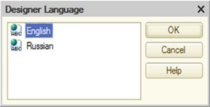
Fig. 133. Selecting the configuration editing language
A similar result can be achieved using the language selection button located in the status bar to the right from the CAP and NUM buttons (bottom right corner of the main Designer window).
The Designer will replace the text of the labels with the labels in the selected language.
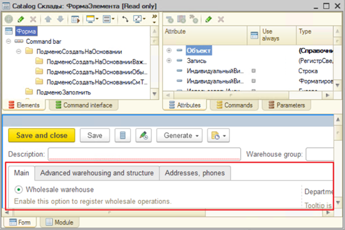
Fig. 134. Form in English
Of course, the text of the labels must be pre-entered for each control. To enter the text in the Label control property palette in the Title property (Text or Synonym, depending on the control type) it is required to click "magnifier" button (see fig. 135). The window Strings in different languages will be displayed.
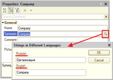
Fig. 135. Strings in different languages
Note. Tip. There are no restrictions on the number of languages in the configuration. However, the objects of the Languages type must not be created "with a reserve", since the Language object can be created at any time.
The Language code property specifies the language code, for example, EN for English.
If two or more objects of the Languages type are defined in the configuration, then for the Synonym and Title properties of the control a button for text editing in different languages appears (in the form of a magnifying glass).
The program creates the first language object in accordance with the choice of language (country) when creating a new infobase.
To generate a text presentation of an attribute for display in a form, the following rule is used:
-
The title of the displayed object is retrieved in the current user's configuration language. If the title is set, it is used.
-
An attempt is made to retrieve a synonym for the displayed object in the current user's configuration language. If a synonym is set, it is used.
-
Further behavior depends on the displayed object type:
-
For standard attributes, the presentation is obtained in the platform localization language.
-
For the objects created by the application developer, the object name is used in the same way (and in that language) as specified in the configuration.
-
Note. IMPORTANT. If texts in theSynonym or Title properties are entered, changing the language code in the Language code property will cause a "loss" of the entered texts (texts will remain for the previous code value). Texts are "restored" when specifying the previous value of the language code.
To edit texts and perform localization tasks (creating an interface in different language), use the Interface text editing mode (see Configuration localization).
If the application is intended to be used on the mobile devices, it is recommended to specify language codes in accordance with ISO 639 standard (http://www.iso.org/iso/ru/language_codes). Otherwise, a warning will be displayed when verifying the configuration.
The following characters are not allowed in the language code: #, *, |, /, :, ", <, >, ?, and /.
5.6. Common configuration object properties
This section describes the common properties of metadata objects.
5.6.1. General properties
Virtually all configuration objects have the following properties, which are located in the General properties category:
-
Name is a configuration object name. The name must consist of one word, begin with a letter and contain no special characters, except "_". The object name is used to access and manage the configuration object using 1C:Enterprise language tools. The names of the configuration objects must not coincide with the reserved words of the query language (for a list of reserved words, see Bilingual keyword presentation). The name of the configuration object cannot exceed 80 characters. Configurations created in 1C:Enterprise version 8.3.6 and earlier may have configuration object names longer than 80 characters, however, if when attempting to edit such object in version 8.3.7 or higher, it will be necessary to reduce the name to 80 characters.
-
Synonym. In addition to the name, its synonym can also be specified. If the configuration is created for use in different languages, the synonyms in the languages used must be specified. When operating the 1C:Enterprise, a synonym will be output in various selection lists, window titles, text labels, when creating interfaces based on the current language. The synonym has no restrictions on the character use. If no synonym is specified, the name is selected.
Note. Note. The name or synonym displayed to the user are also called the configuration object presentation.
- Comment is an arbitrary character string. Usually explains the object name.
5.6.2. Metadata object presentation
The possibility to define various object presentations is implemented for many metadata objects. This is done so that the developer has the opportunity to define the presentation of standard commands, their tooltips and form titles.
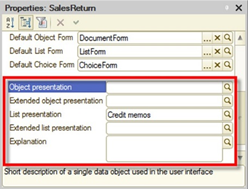
Fig. 136. Objects presentation
-
Object presentation (records for a register):
-
One object name (for example, Current account).
-
Used in the standard command presentation (object creation).
-
-
Extended object presentation (records for a register). Used to generate the object form title. For example, Company current account.
-
List presentation:
-
Object list name (for example, Current accounts).
-
Used in the standard command presentation (command to open the list of objects).
-
-
Extended list presentation. Used to generate the list form (for example, Company current accounts).
-
Extended presentation. Report or data processor form title (for example, Report on current account offsets).
-
Explanation. Used to generate a tooltip for the standard commands (for example, Current accounts of our companies).
-
Image. Image for subsystem presentation in the sections panel.
It should be noted that filling in the properties associated with the presentation of objects and lists is only necessary in cases when it is required to somewhat specify the default information displayed for the object.
For example, there is a Goods catalog (Name of metadata object is Goods, Synonym of metadata object is Goods), where products and services may be its items. But you want to use a singular noun for the command (create product) in the command texts and do not want to reflect information about the services, because it "lengthens" the command text. At the same time, you want to indicate to the user in the object form that both products and services can be edited in this form. In this case the Object presentation is reasonable to be filled with Goods text, and Extended presentation of the object property - with Goods (service) text. Then the command to create an item of the Goods catalog will look like Product: create, and the form title will look like Product (service).
For detailed information on which of the above properties correspond to which metadata objects, see Rules of generating standard command texts and automatic form headers. It is also possible to retrieve the information about the rules for the standard command text, command tooltips and form titles generation there.
5.6.3. Arbitrary data presentation
The standard data presentation which is generated by 1C:Enterprise may not suit the user. For example, if users, that speak different languages, use 1C:Enterprise and the system objects contain all the necessary information in different languages as well. For example, there are two names for products: in Russian and in English. And it is necessary to display the necessary text depending on the session localization code. A presentation in the desired language also must be generated wherever the object presentation is generated: a dynamic list, a report, and so on.
To implement this task, there is a special feature that allows the developer to determine the attributes that are involved in the generation of the presentation, as well as to describe the algorithm using which the object presentation is generated.
This is possible for the following configuration objects:
-
Exchange plans
-
Catalogs
-
Documents
-
Charts of characteristic types
-
Charts of accounts
-
Charts of calculation types
-
Business processes
-
Tasks
-
External data source tables
Presentation generation consists of two stages: identification of attributes involved in presentation generation and actual presentation generation.
To determine the list of attributes, the PresentationFieldsGetProcessing event handler of the corresponding object manager is used. The handler is called at the first attempt to retrieve a selected object presentation, and the result is preserved for the duration of the session. In this handler, the Fields array must be filled with the names of the attributes that will be involved in the presentation generation. If the StandardProcessing parameter in the handler is True, then after the handler completes its operations, the Fields array will be cleared and filled with the fields used to generate the standard presentation of this object. Otherwise, the platform will use only the names of the fields that were placed in the Fields array.
It is not recommended to include the fields of unlimited length in the list of fields used for the presentation. If this is done, then there may be problems when retrieving the field presentation for fields of a union type and when using the presentation in queries with grouping and retrieving unique records.
It is also strongly not recommended to pass reference fields to the field list (including the Reference field) and retrieve the required data using dot from such fields. In this case, the system performance will be drastically reduced due to the fact that the required fields will be retrieved in extremely inefficient way. At the same time, data from fields specified in the Fields parameter will be received in the most efficient way. Besides, objects for which the presentation is generated will not be read unless it is required.
Note. Note. The examples below are not complete. These are intended to demonstrate the techniques of the arbitrary representation operating.
Let us assume that the Goods catalog contain RussianName, EnglishName, and SKU attributes that will used to generate the presentation. In this case, the handler for retrieving the presentation fields (in the Goods directory manager module) will be as follows:
Procedure PresentationFieldsGetProcessing(Fields, StandardProcessing)
Fields.Add("RussianName");
Fields.Add("EnglishName");
Fields.Add("SKU");
StandardProcessing
= False;
EndProcedureIf necessary to retrieve the presentation 1C:Enterprise will call the PresentationGetProcessing handler in the corresponding object manager. The values of the attributes involved in the representation generation are passed to this handler. The program code located in the data processor handles the generation of the presentation text.
Note. Important. The PresentationGetProcessing event handler is called whenever there is a need to retrieve a representation of any infobase object. Excessive data, or the wrong choice of data to generate a presentation, can cause significant 1C:Enterprise performance drop.
The PresentationGetProcessing handler generates the presentation and returns it using Presentation handler parameter. The data necessary for the representation generation are passed using the Data parameter. Data is a structure, where the key is the name of the attribute, and the value is the value of the attribute for the current object. If the StandardProcessing parameter is True, 1C:Enterprise will attempt to generate a standard presentation for the current object, based on the data passed. If the Data parameter contains no attributes necessary for the generation of a standard presentation, then the presentation will be an blank string. If the presentation generation is performed for a new object (not yet stored in the infobase), then the Undefined value will be passed as the value of the Reference field of Data structure.
Consider an example of generating the presentation of bilingual catalogGoods:
Procedure PresentationGetProcessing(Data, Presentation, StandardProcessing)
StandardProcessing
= False;
SessionLocalizationCode = Upper(CurrentLocaleCode());
If Find(SessionLocalizationCode, "RU") <> 0 Then
Text = Data.RussianName;
ElsIf Find(SessionLocalizationCode, "EN") <> 0 Then
Text = Data.EnglishName;
Else
Text = Data.RussianName;
EndIf;
Presentation = Text + "(" + Data.SKU + ")";
EndProcedureIt is worth noting that if 1C:Enterprise language error is made in the PresentationGetProcessing handler, the application may unexpectedly shut down.
5.6.4. Standard attributes
To redefine certain interface properties (such as a synonym, filling check, and so on) of standard attributes (for example, Code, Name, Parent) and standard tables (for example, ExtraDimensionTypes, BaseCalculationTypes) of the applied objects at the configuration level, you can configure these properties.
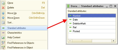
Fig. 137. Standard attributes
To do this, the property palette of several objects has commands that open lists of standard attributes and standard tables (see fig. 137). Such commands are available for objects that have standard attributes and standard tables.
Using the property palette, it is possible redefine certain properties of standard attributes in such a way that these more fully meet the requirements of the applied task being solved. For example, for the Owner property of CurrentAccounts catalog it is possible to set the Counterparty synonym. Then in all the form the default presentation of this attribute (Owner) will be "Counterparty:".
If standard attribute (or standard table) properties are not specified, the default standard attribute properties will be used.
In terms of the set of properties, standard attribute is almost identical to any other attributes, except for the fact that the following cannot be changed:
-
Standard attribute name
-
Standard attribute type
-
Standard table name
-
Standard attribute indexing
Note. IMPORTANT. The presence of the standard attribute description does not change its name, that is, all the calls to the attribute in the 1C:Enterprise language and in the query language remain unchanged.
5.6.5. Predefined data
5.6.5.1. General information
informationPredefined data are the elements of applied objects that are created in Designer and can be accessed by name without prior search. It makes sense to create predefined data in the event that some data element is needed all the time and access to this element from the program code needs to be to simplified. For example, in the Goods catalog, you can create the Service predefined item, which can be accessed as follows: Catalogs.Goods.Service. Both elements and groups of elements can be predefined. Groups can be created when predefined elements are created in hierarchical objects, for example, in a hierarchical catalog. Predefined data can be created for:
-
Catalogs (see Catalogs)
-
Charts of accounts (see Charts of accounts)
-
Charts of characteristic types (see Charts of characteristic types)
-
Charts of calculation types (see Charts of calculation types)
After creating a predefined element in the Designer, the possibility to create or update the associated data element is determined by several parameters:
-
The value of the object property in the infobase. You can get and set the value of this property in 1C:Enterprise mode using theGetPredefinedDataUpdate() and SetPredefinedDataUpdate() methods.
-
Value of the PredefinedDataUpdate configuration object property. Set in Designer.
-
The value set for the entire infobase. You can get and set the value of this property in 1C:Enterprise mode using the GetInfoBasePredefinedDataUpdate() and SetInfoBasePredefinedDataUpdate() methods.
-
Type of distributed infobase node (see Distributed infobases). The value of this parameter is determined automatically:
-
For the root node and non-distributed infobase, the value is Update automatically.
-
For the subordinate node of the distributed infobase Do not update automatically.
-
Each parameter described above can have one of the following values (except for the parameter describing the type of the distributed infobase node):
-
Do not update automatically. In this case, 1C:Enterprise does not create or update a data element when creating or modifying predefined data. It is should be noted that if such property is set for a configuration object, an exception may be thrown when accessing predefined data, since there is no data element associated with the predefined element.
-
Update automatically. In this case, 1C:Enterprise will automatically create (or update the existing) data elements for new (or modified) predefined data.
-
Automatic. 1C:Enterprise automatically determines the need to perform the update.
The action to be performed (to update or not to update) is determined by sequential analysis of the above parameters (in the specified order) until a value other than Auto is found. This value will determine the capability to create or update predefined elements.
The data element and the predefined data element are linked using the PredefinedDataName property. Using this property, you can perform the following actions:
- Associate a predefined data element with a data element. To do this, assign the PredefinedDataName property the name of a predefined data element to be associated with the data:
ElementReference = Catalog.Goods.FindByDescription("Delivery
service");
Object = ElementReference.GetObject();
Object.PredefinedDataName = "Service";
Object.Write();As a result of this operation, the data element with the Delivery service name will be mapped to a Service predefined element in the Goods catalog.
When writing an object, it is checked that there is no other data element in the infobase with the name of the predefined data set to the value which the data element is written with.
- "Unlink" the data element from the predefined data element. To do this it is necessary to assign PredefinedDataName property to a blank string and write an element:
Object = Catalog.Goods.Service.GetObject();
Object.PredefinedDataName
= "";
Object.Write();When attempting to access the Catalog.Goods.Service predefined element after executing the above example, an exception will be generated.
Thus, the process of changing the data element associated with the predefined data is carried out in two stages:
-
"Unlinking" of the existing data element from the predefined element is performed.
-
New data element is associated with the predefined element.
Creating data elements associated with predefined data can be done in one of three ways:
-
Automatically, during the infobase restructuring. This happens in the following case:
-
Automatic creation and update of the predefined data is permitted.
-
Predefined data was previously created in a given data area or infobase.
-
-
Automatically, when accessing the table that stores the configuration object data for the first time. Creation of predefined elements in this case will be performed, provided that the creation of predefined elements is not prohibited.
-
Using 1C:Enterprise language by specifying the PredefinedDataName property when creating data element. This method can be used if the automatic creation of predefined elements is prohibited in the configuration objects properties.
Updating data associated with predefined data will be performed if automatic updating of predefined data is enabled, predefined data is associated with the real data, and predefined data is modified in the Designer. In all other cases, the information entered in the Designer will not be passed to the infobase.
Reordering of predefined items in the predefined tables of the chart of accounts and the chart of calculation types is processed in the related data. The items order in the data will be the same as it is specified in the metadata. The data entered by the user (not predefined) will be located after the predefined ones.
If a predefined data element is deleted in the Designer, the following actions will be performed:
-
The data element associated with the predefined data element will be marked for deletion.
-
The corresponding entries will be deleted from the list of element extra dimension in the chart of accounts.
-
In the lists of leading, base and displacing calculation types, the corresponding records will be deleted.
For the forced creation of predefined data elements (for catalogs, charts of characteristic types, charts of calculation types and charts of accounts), use the InitializePredefinedData() method. Calling this method will force the creation of predefined data elements when the following conditions are met:
-
Predefined elements were not previously created in the current data area.
-
Updating predefined data is configured in such way that the creation and updating of predefined data must be performed.
If the specified conditions are not met, the creation of predefined elements is not performed.
If the automatic updating of the predefined data is disabled in the application, then deleting the predefined element causes a change in the associated data object (if any). The PredefinedDataName property value is replaced with the #xxxxxxxx-xxxx-xxxx-xxxx-xxxxxxxxxxxx value, where xxxxxxxx-xxxx-xxxx-xxxx-xxxxxxxxxxxx is the remoted metadata item UUID.
If it is necessary to retrieve a list of predefined elements for a configuration object, use the GetPredefinedNames() method.
An example of retrieving a list of predefined values:
List = Metadata.Catalogs.Goods.GetPredefinedNames();If the method returns an empty array, the configuration object has no predefined values. Otherwise, it is possible, for example, to perform a check for the presence of a related element in the data for each predefined element.
5.6.5.2. Usage in the distributed infobase
When operating in the distributed infobase mode, predefined elements are passed with the configuration. The data elements associated with the predefined data are passed in the usual way, using an exchange plan. In this case, the automatic creation of predefined data in the peripheral infobase will not occur. For a detailed description of the reason, see General information.
Note. Important. If the data associated with the predefined elements were received by the subordinate node before the configuration with the associated predefined elements, then the automatic "association" of the data and the predefined data will not occur. This will require to re-export the necessary data elements from the central to the peripheral infobase.
If the initial image of the peripheral infobase is created before the operations with the main infobase started, it is possible to use the PredefinedDataInitialization() special method to create predefined elements so that they are automatically included in the peripheral infobase. The method must be called before the creation of the initial image.
When cancelling the master node assignment (for example, to perform any special actions), consider one moment. When determining whether creation or update of predefined items is required, such infobase will not be considered peripheral. Due to this fact, during the first infobase start in 1C:Enterprise mode, the mode for creating or updating predefined items can be defined as Update automatically. To avoid this, use the /SetPredefinedDataUpdate command line parameter (or use the SetInfoBasePredefinedDataUpdate() global context method).
The same method can be used if a universal data exchange functionality between infobases with similar, but not identical standard solutions is used, and it is necessary to make one master infobase (in terms of predefined data). For the infobase where it is necessary to create predefined elements, specify the Create automatically value, and for the other infobase specify Do not create automatically. In this case, the association between the configuration element and the data object will be performed by the predefined element name.
Also, when using a universal data exchange functionality, the following peculiarities must be considered:
- When writing a data object that is predefined in the source infobase, 1C:Enterprise checks for the presence of the same predefined data name in the type-forming configuration object. If such name exists, the object will be imported without changes. If there is no such name, the PredefinedDataName property will be cleared for the object during import.
For example, a universal data exchange between the same infobases is performed. Each infobase contains the Products catalog. This catalog in each infobase contains the Service predefined element. References to these data objects are different.
Then during import, 1C:Enterprise will detect the Service predefined item in the target infobase and perform import with the PredefinedItemName property. This will be possible if theDataExchange.Import property is set to True before the element is written. Otherwise, an exception is thrown.
However, when attempting to access the Service predefined element in the target infobase, an error will occur, since 1C:Enterprise cannot have two objects associated with the same predefined element.
This situation must be avoided. An application developer must independently handle an attempt to import a data object with a duplicate name of predefined data.
- When importing the data object, which predefined data name references the remote element (in #xxxxxxxx-xxxx-xxxx-xxxx-xxxxxxxxxxxx format), such element will be written in any case. However, 1C:Enterprise will not permit to write two objects that reference one remote predefined element (with the same predefined data name value), except for the case when the DataExchange.Import property is set to True before the element is written.
To disconnect the infobase from the master node when using subordinate data, follow the recommendations described inGetting and setting a distributed infobase master node.
5.6.5.3. Separation mode operation
For details on operating in a separated infobase, see Predefined data.
5.6.6. Objects numeration
5.6.6.1. General information
There are objects in 1C:Enterprise that must be numbered automatically or manually. Numbering is available for the following objects:
-
Catalogs
-
Documents
-
Charts of characteristic types
-
Business processes
-
Tasks
-
Exchange plans
Depending on the object, various types and numbering modes are available. Numbering can be performed for the number (documents, business processes, tasks) and code (all other objects). Consider the numbering peculiarities of objects in more detail.
Code/number type
The code/number of the configuration object can be numeric or string type.
If the code/number is set as string, then several different additional features appear:
-
The code/number can consist not only of numbers, but of any available characters.
-
Available code length defines the code/number length. If this property is set to Fixed, the length of the code/number will always be equal to the value specified as the Code length or Number length property. In this case, the line will be supplemented with spaces. If the property is set to Variable, then the length of the code/number cannot be greater than the value specified in the Code length or Number length properties, but the actual length will be determined by the number of characters involved in generating the number.
-
For the code/number, you can set different prefixes (see Numbering prefixes).
When using a string code/number it is necessary to understand how the numbering works. Consider the numbering example. Catalog code type is String. Code length is 3 characters. Assume the operator entered the number 01 and wrote the catalog element. As a result of this action, the maximum value of the number that can be created by the automatic numbering system will be 99. This happened because the manual entry of a new number resulted in an obvious limitation of the number length to two digits. The automatic numbering system "cannot" automatically expand the number created if the number length is explicitly limited.
Thus, for the automatic numbering of string codes/numbers to operate, it is recommended either not to specify numbers manually or to set leading zeros so that any code/number is always the maximum possible length (including the leading zeros).
It is also worth remembering that specifying leading zeros will ensure the correct sorting of codes/numbers in case if the code/number type is a string.
Automatic numbering flag
This property determines whether the system will automatically assign a code/number to a new object when the object is written. If the automatic numbering is enabled, 1C:Enterprise has the following behavior:-
A code/number is assigned that does not coincide with any number in the infobase.
-
The code/number assigned must be 1 greater than the maximum of the code/number among the objects in the infobase (which are involved in numbering) and the codes/numbers assigned to the objects not yet recorded in the infobase.
-
When deleting or manually decreasing the maximum code/number, the numbering (if possible) continues from the maximum remaining number/code. Continuation of numbering from the lowest possible code/number is generally not guaranteed.
Uniqueness check
This property determines whether the system will control the uniqueness of the code/number for the object. The control will be performed both for the automatically assigned code/number, and for the code/number that is specified manually.Numerator
For documents, you can specify a Numerator. It allows you to ensure a common number space for several different types of documents. For more information about numerators, see Numerators.5.6.6.2. Code/number series
For catalogs and charts of characteristic types, it is possible to indicate how the new number will be generated. This can be done using Code series property:
-
In entire catalog/In entire chart of characteristic types. When generating a new code for an item of a catalog/chart of characteristic types, a code will be generated that is unique in the entire catalog/chart of characteristic types.
-
Within subordination area. When generating a new code for an item of a catalog/chart of characteristic types, a code unique within the item hierarchy will be generated (items having the same parent will have different codes, items having different parents may have the same codes).
-
Within owner subordination area. When generating a new code for a catalog item, a code unique within the subordination will be generated (items having the same owner will have different codes, items having different owners may have the same codes). This option is applicable only for catalogs.
5.6.6.3. Code/number periodicity
For documents and business processes it is possible to ensure the periodicity of numbers. This means that the numbering will start from the beginning, each time a new period begins. Periodicity is configured using the Periodicity property. This property can have the following values:
-
Nonperiodical. Numbering does not depend on time periods.
-
Within a year. Numbering starts from the beginning with the new year beginning.
-
Within a quarter. Numbering starts from the beginning with the new quarter beginning.
-
Within a month. Numbering starts from the beginning with the new month beginning.
-
Within a day. Numbering starts from the beginning with the new day beginning.
The uniqueness control during periodic numbering will be performed within the established period (for a year, quarter, month or day). If nonperiodic numbering is set, then uniqueness will be controlled in all the existing objects of this type.
Belonging to a particular period is determined by the date of the document or business process, and not by the current date. Due to this, a change of the document or business process date may cause a number change in the case when the new date refers to a different periodicity (if set).
5.6.6.4. Numbering prefixes
When automating various tasks, there may be a task of ensuring separate numbering of objects of the same type depending on certain conditions. For example, the records are kept on behalf of several firms in the infobase, and each firm needs its own numbering of documents. This problem is solved using the code/number prefixes. The code/number prefix is a sequence of characters that precede the code/number within which the objects are numbered. The use of numbering prefixes has several features:
-
Prefixes are used with a string code/number type only.
-
The code/number length, when using the prefix, may be greater than without using the prefix (by the prefix and the separator size). Thus, if the code length was initially set to 6 characters, and it is necessary to start using the prefix 3 characters long, to preserve the numbering space of 6 digits, it is required to increase the code/number length to 9 characters (6 characters the code itself and 3 characters prefix).
-
To automatically change the prefixes depending on the object attribute values, it is necessary to perform additional actions in 1C:Enterprise language.
To set a new number, with the prefix, the OnSetNewCode()/OnSetNewNumber() handler or SetNewCode()/SetNewNumber() methods must be used with specifying of the required prefix. If the prefix is not specified or not fully specified, then among the prefixes existing in the information base, the maximum prefix will be determined (in alphabetical order) and a new number will be received within this prefix.
Consider examples of the numbering system behavior.
There are two objects, for which A-151 and B-152 numbers are specified. When setting the new code for A– prefix, A-152 number is received, and for B– prefix, B-153 number is received. If 1C:Enterprise contains objects with the following numbers: AA151, AB150 or BC114, then, depending on the set prefix, several variants of received numbers are possible. Each description of the prefix actions proceeds from the starting number values and does not consider the actions of other examples:
-
AA prefix is specified. AA152 number will be received in this case.
-
AB prefix is specified. AB151 number will be received in this case.
-
A prefix is specified. AB151 number will be received in this case. This number will be received as a result of the fact that the prefix is not fully specified and 1C:Enterprise will determine the maximum prefix (in alphabetical order). This prefix will be AB and within this prefix the new number is received: AB152.
Consider an example of setting a prefix depending on the object attribute value.
Assume, that we have a document that contains an Organization attribute of CatalogRef type. The Prefix attribute (of String type) in the Organizations catalog contains the document number prefix. Thus, each organization will maintain its own unique numbering. To assign a prefix, in the object module of the document used create a OnSetNewNumber() handler, where the document number prefix will be set depending on the organization selected in a particular document instance.
Example:
Procedure OnSetNewNumber(StandardProcessing, Prefix)
Prefix = Organization.Prefix+" ";
EndProcedure5.6.6.5. Automatic numbering feature peculiarities
Control of the object code/number uniqueness, if the Uniqueness control property is set, is performed when it is written, regardless of the objects automatic numbering mode and how the object is assigned a new code/number manually or automatically. If the object is written in the "import mode" (when the object is written, the DataExchange.Import property is set to True), the code/number is not checked for uniqueness.
5.6.7. Input by string
5.6.7.1. General information
For applied objects (catalogs, documents, charts of characteristic types, charts of accounts, charts of calculation types, registers, business processes and tasks, as well as exchange plans), it is possible to specify the attributes which are used for searching in the Input by string property. If the input by string is permitted (the corresponding attributes are set), then it is permissible not to perform a selection from the object form in the corresponding type input field, but to enter the data that is contained in the set object attributes.
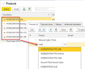
Fig. 138. Input by string
For example, we have the Products catalog, which contains several products starting with the word Bosch. Then, by entering the word bosc in the product input field, we get a list of products that begin with this word (see fig. 138).
The string that is entered in the input field to be further used for searching must meet the following requirements:
-
The total string length must not exceed 1,000 characters.
-
This string must not contain more than 32 words (with spaces, non-breaking spaces, and tabs as separators).
If the entered string does not meet one of these requirements, the search will not be performed, and you will see an error message.
The following may be used as the attributes using which the search is be performed:
-
For catalogs, charts of calculation types, charts of accounts, charts of characteristic types, exchange plans: Code and Description.
-
For documents: Number.
-
For business processes and tasks: Number and Description.
-
Attributes of the Number or String type, for which Index property is set to Index or Index with additional ordering. An example of the latter is the field for entering the SKU, barcode, TIN.
To generate a list of attributes, click the select button and in the opened dialog box move those fields, for which the input by string is supported, to the left list.
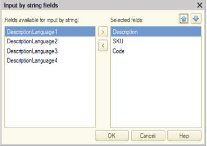
Fig. 139. Configuring input by string
If there are several fields, then set their sequence. When searching by string, the search is performed in the fields in sequence in which they are presented in this dialog box. For example, for the Products catalog element, input can be carried out both by code and by SKU. If the value of the one element code matches with the value of the SKU of another element, then the found values will appear in the list of values in the order in which they were specified during configuration.
Note. IMPORTANT. When performing a data search (during input by string), data access restrictions apply (see Data access restriction).
In addition to specifying which fields will be searched, 1C:Enterprise allows you to further customize some search parameters. The String search method property is used to specify the string search method:
-
Only in the beginning of the field selected for input by string (Beginning value). In this case, the search string is not broken into words, and the entered text is searched entirely. For example, the search is performed in the following data: John Miller and Johnson. If you enter John in the input field, Johnson will be found as a result. However, if you enter John Mil in the input field, nothing will be found.
-
In any part of the field (Any part value). If the search string consists of several words and the search is performed in any part, then the search uses a query similar to the following (for two fields and two words):
(Field1 DETAILED "%Word1%" Or Field2 DETAILED
"%Word1%") AND (FIeld1 DETAILED "%Word2%" Or Field2
DETAILED "%Word2%")The Full-text search property allows you to use full-text search when arranging the input by string. Full-text search cannot be used for external data source tables. The use of full-text search has several features:
-
Full-text search is always performed by the beginning of words.
-
Full-text search is used for the initial filtering of objects in which further search will be performed (the number of objects in which the search will be performed is reduced).
-
All the non-indexed references from the table, which was used for the input by string, will be added to the results of the full-text search.
-
In the list of selected objects, the search will be performed by the fields that are selected for use in the input by string functionality in the manner specified by the String search method property.
-
For each word from the search query, the "*" character is added at the end.
These features can cause the following consequences:
-
The data will be found if the line search method is set in the value Any part and requires to search the fragments located at the beginning of words.
-
The data will not be found if the line search method is set in the value Any part and requires to search the fragments located not at the beginning of words. It is recommended disabling the full-text search if the line fragments located not at the beginning of works are needed to be found. The line search method may be left unchanged.
-
If the full-text search fails, the usual search will be applied, in accordance with the String search method property. This can lead to a situation where the object found turns into a not-found one (for the search by any part of a word). For example, the "a" character is entered in the input field. This character is located not only in the beginning, but also in the middle of the word array where the search is performed. For a large data set, the full-text search will terminate with an error (the search result is too large) and using the normal search, data will be found that contain the letter "a" inside. Then the user enters another letter (for example, "ц") and the search string will become "ац". In this case, full-text search will only filter data that starts with "ац" and will ignore data that contains "ац" within.
If the drop-down list is generated by 1C:Enterprise (and not using the application program code), then the presentations of the found objects are generated using a special algorithm. The presentation of the found object consists of two parts: presentation of the attribute that contains the search string (required) and additional presentation (optional).
The presentation itself is generated as follows:
-
The field containing the search string is determined:
-
In the case of using full-text search or in the normal search for several words, this field will be the first field from the fields specified in the Input by string property in which the first word from the search string is found.
-
When using the normal single word search, this field will be the attribute in which the search was performed.
-
-
The presentation of a value located in a specific field will be a mandatory part of the presentation of the found object for the drop-down list.
-
It is determined whether it is necessary to generate an additional presentation. For this, the components of the fields is determined, which will be used to generate an additional presentation:
-
If the object found has only one field used to generate the presentation, and the search string is found in this attribute, the fields of the alternative presentation are used.
-
Otherwise, the default presentation fields are used. The list of the default and alternative presentation fields is given below.
-
-
If the list of fields to generate an additional presentation is empty, the additional presentation is not generated. Otherwise, the additional presentation is generated as follows:
-
Text presentation of all the fields that are selected to generate an additional presentation is enclosed in parentheses and separated by ",".
-
The generated additional presentation is added to the right, separated by a space, to the mandatory part of the presentation of the object found.
-
-
The following fields are used to generate the default and alternative presentations:
-
Catalog, business process, chart of characteristic types, chart of accounts, chart of calculation types:
-
Default presentation: Description and Code.
-
Alternative presentation: depending on the selected default presentation, the remaining field is used for the alternative presentation.
-
-
Document:
-
Default presentation: Number and Date.
-
Alternative presentation: none.
-
-
Task:
-
Default presentation:Description, Number, and Date.
-
Alternative presentation: none.
-
-
External data source:
-
Default presentation: field specified in the Presentation field property of the external data source table (see External data source tables).
-
Alternative presentation: none.
-
-
The Selection data retrieval mode property controls how the platform searches for data when input by string. If the property is set to Background, then a background job is used to retrieve data, and an animated image is displayed in the drop-down list, similar to the background report execution (see Background report execution). The background job is used if the required data has not been received for display to the user within 200 ms. For the infobase file mode, it is possible to retrieve data in the background if another background or scheduled job is not performed at the time of receiving the data. During the background retrieval of selection results, the user can continue to edit the input field. By specifying the Directly value as a property value, the search is performed without using background jobs.
When configuring input by string it is recommended to observe the following recommendations:
-
The Background value for the Selection data retrieval mode property is recommended to be set for objects where a large amount of data is planned.
-
Enabling full-text search is recommended for the objects in which a large amount of data is expected.
-
It is recommended to enable the string search in any place alongside with a background search, or in tables, where a large amount of data is not expected. It is desirable, also with a large amount of data, if the search in any place is enabled, to enable the full-text search (so that most of the searches would be performed through full-text search).
5.6.7.2. Input field behavior features
When entering data in the input field, consider some features of operating the selection list. If input results in finding several objects, beginning with the entered text, the list of these objects will be located in the drop-down list. During input, the user can use the Up arrow and Down arrow buttons to move through the list, while continuing to type in the field itself. In this case, to make a selection, it is necessary to select the required element and confirm the selection by pressing the Enter or Tab button. To generate a selection list for the input field, the following algorithm is used:
-
Data is retrieved when performing a search in the first field (from the list of selected fields) by the beginning of a string and by substring. The quantity of records retrieved as a result of the search by the beginning of the string will be called RS, and the quantity of records retrieved as a result of the search by substring will be called RP.
-
If RS+RP<=10, the drop-down list will contain all the results of each search.
-
If the RP and RS exceed 5 (each), the selection list will contain 5 records from each list.
-
If any of RP or RS values is less than 5, then all the entries from the smaller list and as many records from the larger list as required to complete the drop-down list to 10 will be added to the drop-down list.
-
If the total quantity of records in the drop-down list turned out to be less than 10, then the algorithm is repeated from step 1 for the next field from the list of selected fields, using the difference between 10 and the quantity of results retrieved as the number of data necessary for retrieval during the next step.
5.6.7.3. Selection list programmatic generation
If the developer is not satisfied with how the selection list is generated, they can override it themselves. This can be done in two ways:
-
Directly in the form. In this case, the special generation of the selection list can only be used for this single field. To do this it is required to define StartChoice, AutoComplete and TextEditEnd event handlers.
-
In the corresponding object manager module. In this case, special selection list generation will be performed for all the input fields in which the values of the used object are entered.
If the field is associated with data that has a type of reference to an applied object (for example, CatalogRef, EnumRef, and so on), the selection list can be generated either in the corresponding object manager module or using form module handlers. In other cases, the selection list can only be generated using the form module handlers.
Let's take a closer look at how the selection list is generated in the object manager.
To programmatically generate a selection list, it is necessary to redefine the ChoiceDataGetProcessing event handler of the object module. The handler receives a set of parameters that determine the conditions for selection list generation (via the Parameters handler parameter). A parameter set is a structure that contains:
- Search string, a text string containing the text that the user entered in the input field (SearchString property).
When performing standard data processing, the following assumptions regarding the search string are used:
-
If this parameter is not specified or its value is Undefined, it is considered that the search string is not specified and it is necessary to return the entire available list of values.
-
a value of any type other than the String type, which is specified as the value of the SearchString property, will be converted to a string value.
-
Filter is the structure that describes the filtering, as it is described by the Filter form parameter of the form extension for a dynamic list. This property is always present.
The filter specified in this property will be converted (if possible) into a full-text search query, refining this query to increase the search speed.
-
The property that indicates the mode of selecting groups and elements (transferred only for hierarchical lists) is the ChoiceFoldersAndItems property.
-
The StringSearchMode property that defines the string search mode: by word beginning or by any part.
-
The need to use full-text search (the FullTextSearch property).
-
The mode of selection data retrieval (the ChoiceDataGetMode property).
-
The LimitSearchString property that indicates whether to analyze fulfillment of the search string requirements: its total length cannot exceed 1,000 characters and 32 words. If you want to allow violation of these requirements for the search string, set the LimitSearchString property to False.
-
In addition, the structure passes the items, specified in the Selection parameter associations (see Choice parameter links) and Selection parameters (see Choice parameters) form item properties.
The handler also has two more parameters. The formal parameter (ChoiceData) is used to return the generated selection list. The StandardProcessing parameter determines the system behaviour after closing the handler. If the developer sets the StandardProcessing parameter to False, then they need to completely generate the selection list themselves.
If the standard processing checkbox is selected to True, 1C:Enterprise can be allowed to generate a selection list, but you can also modify the selection parameters (add additional selection values, change the selection mode for groups and items, and so on).
Note. Note 1. If 1C:Enterprise independently generates a selection list, the data access restrictions are applied when generating the list (see Data access restriction).
Note. Note. The examples below are not complete. These are intended to demonstrate the various features for selection list retrieval.
So, when the user enters any text, the following code will provide three products with codes 00000002, 00000003 and 00000004 for selection.
Example:
Procedure ChoiceDataGetProcessing(ChoiceData, Parameters, StandardProcessing)
ChoiceData = New ValueList;
ChoiceData.Add(Catalogs.Goods.FindByCode("00000002"));
ChoiceData.Add(Catalogs.Goods.FindByCode("00000003"));
ChoiceData.Add(Catalogs.Goods.FindByCode("00000004"));
StandardProcessing = False;
EndProcedureIn the following example, setting an additional filter expands the filter generated by the input field so that the selection list contains only goods and not all other item kinds. In this case, 1C:Enterprise performs the selection list generation.
Example:
Procedure ChoiceDataGetProcessing(ChoiceData, Parameters, StandardProcessing)
Parameters.Filter.Insert("Type", Enumerations.ProductTypes.Product);
EndProcedureThe following example illustrates a simplified filter implementation using only 1C:Enterprise language. In this example, the filtering of products which names begin with the string entered by the user in the input field will be considered.
Example:
Procedure ChoiceDataGetProcessing(ChoiceData, Parameters, StandardProcessing)
StandardProcessing = False;
Query = New Query;
Query.Text = "SELECT ALLOWED
| Goods.Reference as Product
|FROM
| Catalog.Goods AS Goods
|WHERE
| Goods.Description LIKE
&Description";
Query.SetParameter("Description", Parameters.SearchString
+ "%");
Result = Query.Execute();
ResultsTable = Results.Export();
ProductsArray = ResultsTable.UnloadColumn("Product");
ChoiceData = New ValueList;
ChoiceData.LoadValues(ProductsArray);
EndProcedureThere is also another way to generate a selection list. Instead of passing a reference to the searched object (as in the examples above), you can pass a structure of special content as an item value of the value list.
This structure consists of the following elements:
- Value. A selected value. It can be a single value or a value array. Structure element with this name is mandatory.
If the Value structure item contains an array of values, this is useful only for input fields that support multiple choice. In addition, the selection list will display the entire group of values (located in the array) as a single value, and all other structure properties (Warning, DeletionMark, and AdditionalData) will be related to the entire list of values as well.
-
DeletionMark. Indicates that the selected value is marked for deletion in the infobase. Structure element with this name is optional.
-
Warning. Line with the warning text that 1C:Enterprise will display when selecting such element from the list of values. Structure element with this name is optional.
-
AdditionalData. This structure item can contain various data that might be required later when operating with the selection list. For example, you can process the value in the handler of the ChoiceProcessing event of the form item. The data will be passed via the AdditionalData event handler parameter.
You can specify additional data in any of the following event handlers: StartChoice, TextEditEnd, or AutoComplete. In other words, in any handler where a selection list is generated to be displayed in the input field.
If the DeletionMark property is True and Warning property is not specified in the structure, 1C:Enterprise will automatically generate the warning text. If the Warning property is specified, then it is displayed. Remember, that the Warning text ends with the question Continue? and is displayed as a question with Yes and No options.
Next, a modification of the previous example will be shown, where for warehouses with the DontUse attribute set to True, a This warehouse must not be used warning will be generated.
It is also possible to combine both values of Structure type and simple values in a single selection list.
Example:
Procedure ChoiceDataGetProcessing(ChoiceData, Parameters, StandardProcessing)
StandardProcessing = False;
ChoiceData = New ValueList;
// Generate a list with warnings
Query = New Query;
Query.Text = "SELECT
| Warehouses.Reference, | Warehouses.Description, | Warehouses.DontUse
|FROM
| Catalog.Warehouses AS
Warehouses
|WHERE
| Warehouses.Description LIKE
&Description";
Query.SetParameter("Description", Parameters.SearchString
+ "%");
Result = Query.Execute();
SelectionDetailRecords = Result.Select();
While SelectionDetailedRecords.Next() Do
Structure = New Structure("Value", SelectionDetailRecords.Reference);
// Fill in the warning
If SelectionDetailRecords.DontUse Then
Structure.Insert("Warning", "This warehouse must
not be used!");
EndIf;
Item = ChoiceData.Add();
Item.Value = Structure;
Item.Presentation = SelectionDetailRecords.Name;
EndDo;
EndProcedureNote. Note. If element presentations (including the structure elements with the Value name) are not specified explicitly, these will be retrieved automatically.
The following example shows how to generate an array of values as a single value of the input field selection list:
Procedure ChoiceDataGetProcessing(ChoiceData, Parameters, StandardProcessing)
StandardProcessing = False;
ChoiceData = New ValueList;
ArrayOfValues = New Array;
// Generate a list with warnings
Query = New Query;
Query.Text = "SELECT
| Counterparties.Ref AS Ref, | Counterparties.Description
AS Description
|FROM
| Catalog.Counterparties AS
Counterparties
|WHERE
| Counterparties.Description
LIKE &Description";
Query.SetParameter("Description", Parameters.SearchString
+ "%");
Result = Query.Execute();
SelectionDetailRecords = Result.Select();
While SelectionDetailedRecords.Next() Do
ArrayOfValues.Add(SelectionDetailRecords.Ref);
EndDo;
Structure = New Structure("Value", ArrayOfValues);
Structure.Insert("AdditionalData", "Here you can
specify additional data");
Structure.Insert("DoMessageBox", "Select multiple
counterparties." + Chars.LF);
Item = ChoiceData.Add();
Item.Value = Structure;
Item.Presentation = "List of counterparties";
EndProcedure5.6.8. Table
Most metadata objects can include tables. Table is a part of a configuration object that contains data with the same structure but varying quantities. For example, each counterparty can have multiple contact phone numbers, each user can have multiple memorable dates, and so on. An important thing is that you cannot create a reference to a table row. This is because an object table row is an integral part of the object. This leads to a simple recommendation for choosing between a table or a subordinate catalog to store a data set related to a reference object: if you might need to create a reference to the stored object, it is better to implement it as a subordinate catalog. If you do not need a reference, you can implement it either as a table or as a subordinate catalog.
Configuration objects can have several tables. If a configuration object can include tables, it will have a Tables branch in the metadata tree.
Like any other metadata object, a table structure consists of attributes. The number of records a table can have is determined by the Line number length property. The value of this property can range from 5 to 9. Thus, a table can contain from 99,999 (just under 100,000) to 999,999,999 records (just under 1 billion). The Line number length table property can only be modified for reference objects (see General information), meaning objects that are stored in the infobase. For reports and data processors (including external reports and data processors), the number of table rows is unlimited.
Let us briefly examine the object table API. To change the data stored in the table, obtain this data as a value of the *Object type (CatalogObject, DocumentObject, and so on). To perform this operation, use the GetObject() method. This loads all object tables into memory. You do not need to create an object in memory to retrieve table data.
To get the total number of rows in the table, use the Count() method. You can iterate through the table rows using a loop:
-
Any loop that calculates the index of a table row. To retrieve a 1C:Enterprise language object that describes a table row, use the [] statement.
-
Using the "For each" loop. In this case, a 1C:Enterprise language object that describes a table object will be contained in the loop statement variable.
To add a row, use the Add() or Insert() methods. The first method returns an object that describes a new row that is added to the end of the table. The Insert() method adds a string to the specified location using the method parameters. Table row attributes are populated by assigning values, similar to any other configuration object.
If we need to add some information to the Goods table of the document, it might look as follows:
pageProduct = Goods.Add();
pageProduct.Product = RefProduct;
pageProduct.Count = 1;
pageProduct.Price = RefProduct.RetailPrice;
pageProduct.Amount = pageProduct.Count * pageProduct.Price;To order the table, use the Sort() method. The first parameter specifies the list of columns to sort by. You can specify one or several columns. In this case, the second column will be sorted for identical values in the first column, and so on.
Another method for changing the sequence of rows in a table is the Move() method. This method allows you to move the row specified by the first parameter by a certain number of positions to the beginning of the table (the Offset method parameter is less than 0) or to the end (the Offset method parameter is greater than 0).
To delete a row, use the Delete() method, which deletes a table row identified either by a row index (the Number type) or an object describing the table row. Note that deleting rows in a loop will disrupt the row indexes or the iterator position. So, in such cases, either create a separate array of objects to be deleted and then delete them by "references" from this array, or perform deletion during a reverse(!) table iteration (from the end to the beginning). In this case, the rows to delete will not affect the iteration through the table. To clear a table, use the Clear() method.
To get a row index by its object or an object by its index, use the following methods:
-
Index(). Gets the index of a row in a table when there is a direct reference to the table row (for example, received when iterating through the collection).
-
Get() is used to get a row from the table if there is an index for this row. The Get() method is an analog of the [] statement.
The Total() method sums up the values (with their sign) for the specified column. Only values of the Number type are summed up.
The Collapse() method allows you to sum up the values of table columns by grouping columns. As a result of executing the method, only rows containing unique values in grouping columns will remain in the table. The summary columns will contain the sums of values for the corresponding combinations of grouping columns. In this case, the redundant table rows will be deleted. The Collapse() method must include all columns of the table to which it is applied. Each column must be either in the list of grouping columns or in the list of summary columns. A column cannot be in both lists simultaneously.
For example, if there is a table that looks as follows:
| Product | Count |
|---|---|
| Phone | 10 |
| Case | 15 |
| Phone | 5 |
| Case | 3 |
If you apply the Collapse("Product", "Count"); operation to this table, the result is the following table:
| Product | Count |
|---|---|
| Phone | 15 |
| Case | 18 |
The number of rows will be less, since rows with the same value in the "Product" column will be collapsed.
To find rows that contain specific values in columns, use the Find() and FindRows() methods:
-
To search for a unique value in the table, use the Find() method. For this method, specify the search value and a list of columns in which this value can be found. It returns either a single row (if the value is found) or Undefined.
-
To find multiple rows that contain the search value, use the FindRows() method. The filter by rows is set by a value of the structure type, where the Key of the structure element is a name of the search column, and the Value is a value to search for. The found rows are returned as an array.
To export a table to the ValueTable object, use the Export() method. The Export method allows you to export all or several table rows that contain all or several columns to the ValueTable type object. Columns are defined by simply listing the names. Rows are specified either by an array of references to table rows or by row filter criteria. The UnloadColumns() method is another method to export the table. This method generates a ValueTable object, which contains either all (if the method parameter is not specified) or only specified columns. You cannot specify a row filter for this method.
When importing a table from a value table (the Load() method), the table is cleared and populated with new rows. The resulting table will have the same number of rows as the initial value table. The columns will be mapped by name.
To export or populate a table column, use the UnloadColumn()/LoadColumn() methods. The UnloadColumn() method exports all values of the specified table column into an array. The values will be exported in the order of table row indexes. The LoadColumn() method transfers the values from the array to the specified table column. The values will be imported in the order of source array indexes.
Also consider that the object table closely resembles the ValueTable object, which supports data exchange.
5.6.9. Forms
Form is an object created for any information input and viewing, as well as for managing various processes. The application uses forms to ask the user for the required information, or to display data for the user to view and edit.
In cases where it is necessary to ensure that the configuration functions simultaneously in the ordinary and managed modes, additional metadata object forms can be used. In this case, 1C:Enterprise will automatically select the form that corresponds to the current mode of operation.
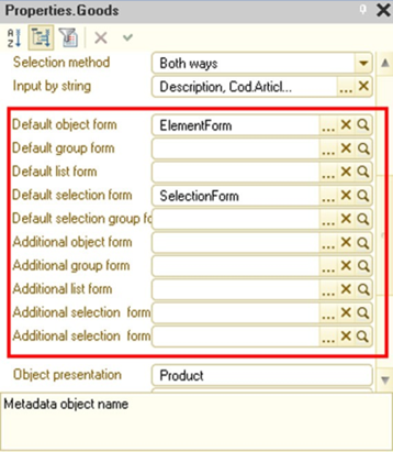
Fig. 140. Main and additional forms
The thin client and web client operate managed forms only. That means that:
-
If both assigned forms are managed, then the form that is assigned as the main one will be opened. If there is only one managed form among the assigned forms, it will be opened.
-
If the managed form is not assigned, it will be generated automatically.
When selecting a form, a thick client attempts to choose a form that most closely matches the current operation mode: If no forms are assigned, the following will be generated:
-
In ordinary mode: an ordinary form.
-
In managed mode: a managed form. If only one form is assigned, then it will be opened. If two forms are assigned, ordinary and managed one, the following will be opened:
-
In ordinary mode: an ordinary form.
-
In managed mode: a managed form. If two ordinary or two managed forms are assigned, the form that is assigned as the main one will be opened.
A double set of forms can be used in cases when the configuration is transferred from unmanaged to managed mode, or it is necessary, for example, to make some configuration options available in a web client (or thin client). In this case, it is possible to implement the necessary features in managed forms and specify them as additional forms. Then, when operating in the web client (or thin client) mode, the necessary forms (managed ones) will be used.
However, it should be noted that theUse managed forms in an ordinary application and the Use ordinary forms in a managed application configuration properties affect the retrieval of default forms in a thick client:
-
If theUse managed forms in an ordinary application configuration property is False, then when receiving the default form in the ordinary mode in the thick client, the ordinary form must be retrieved. If neither main nor additional form is ordinary, then the ordinary form is generated.
-
If the Use ordinary forms in a managed application configuration property is False, then when receiving the default form in the managed mode in the thick client, the managed form must be retrieved. If neither main nor additional form is managed, then the managed form is generated.
If as a result the form that is automatically generated by 1C:Enterprise is opened and the client application startup mode differs from the startup mode set in the Main startup mode configuration property, then the object forms and record set forms open in the View only mode. Also, there will be no Generate commands in list forms and object forms, and no Create command in list forms, if 1C:Enterprise requires to automatically generate a form suitable for the current startup mode to execute these commands and the startup mode of the client application differs from the startup mode set in the Default run mode configuration property.
If the managed application is selected as the main startup mode of the application, then for each managed form of the application, it is possible to choose the purpose of the form. The Purpose of use form property is equivalent (by contents and use) to a similar configuration property (see Specifying general properties). The form editor behavior depends on the intersection of the configuration and the specific form purpose set.
If there is no Personal computer value in the intersection, then:
-
Attribute, parameters, commands, elements properties that are not supported by the mobile platform are not available in the property palette.
-
Editing the context menu of a form element is not available.
-
Editing the extended tooltip for a form element is not available.
-
The types of form fields that are not supported by the mobile platform are not available (see Forms).
-
The dynamic list settings editor does not allow you to expand available fields as the dynamic list operates with one table only on the mobile platform.
If there is no Mobile application value in the form purpose, then it is not included in the mobile application configuration.
5.6.10. Commands
There are commands for the object to perform operations related to a specific metadata object. Non-parametrized object commands will be available in the command interface of the subsystem that include metadata object. In case the command is parametrized, it will be available in the forms that contain form attributes (including first-level subordinate attributes of the main form attribute) of the same type as the command parameter.
The command execution procedure is required for the commands. To create it, use command module, in which you have to implement the CommandProcessing() handler. Precede this procedure by the &AtClient directive, as commands are executed in the client application. However, other procedures and functions located in the command module can be preceded by other directives if this is required for command execution.
Command module must include, for example, opening the report form with the pre-set parameters for printing the card of a specific accounting report or opening the products list form with the pre-set filtering by the product type. If the command from the Navigation panel group must open the same form in different tabs, then when receiving (or opening) the form you must specify the uniqueness key or the key form parameter.
Note. Note. If the command is located on the navigation panel of the main application window (seeApplication interface), the repeated selection of this command will not lead to its repeated execution. This is true for standard commands and commands created in the configuration.
5.6.11. Feature for filling new object attributes
New object attributes can be entered: during interactive creation (except copying); when generating; when using OpenForm()/GetForm() methods; or when calling the Fill() method explicitly. The following can be entered:
-
Filter values when entering from the list:
-
Specific values entered in attribute properties of the configuration (filling values).
-
Values that the developer specified in the Filling() event handler.
The filling processing feature is implemented in the following objects:
-
Exchange plans
-
Catalogs
-
Documents
-
Charts of characteristic types
-
Charts of accounts
-
Charts of calculation types
-
Information register record sets
-
Business processes
-
Tasks
To get a filling data the FillingProcessing() handler has the FillingData() parameter. Depending on the way the handler was called, the FillingData parameter value might be as follows:
-
Generation. The link to source object is transferred as the parameter value. The value of FillingData parameter will contain the link to the source object.
-
Entering from the list with the set filter, the parameter value is the structure composed of the filter items with the Equal to or In list comparison type (the list includes only one value). When creating a new document from the document journal form, the elements of by-column filter are preliminary transformed in such a way that the FillingData structure element name is document attribute name, not the journal column name.
-
Entering new object or record without filter. The parameter value is Undefined.
-
Entering new object or record with global command. The parameter value is Undefined.
-
Programmatical execution of the OpenForm()/GetForm() methods, when executing the OpenForm()/GetForm() methods, leads to creating new object form, the FillingData handler parameter value will be transferred as a value (the Structure type) of the FillingValues form parameter. If the FillingValues parameter is not specified in the form parameters, the handler parameter value will be Undefined.
-
Programmatical call of the Fill() object method. The information that was transferred as the Fill() method value is transferred as the parameter value.
The interactive object creation operation is processed in OnCopy event handler of the object. When processing object creation via copying, remember that ValueStorage-type attribute will not be transferred automatically to the object created. Transferring such data must be explicitly described in OnCopy event handler of the object created.
Filling attributes from filling data is affected by the Fill from filling data property of the metadata object attribute. If this property is set to True, the attributes will be automatically specified by 1C:Enterprise from the filling data. If this property is set to False or the filling data lack the required value, 1C:Enterprise will try to fill the attribute from Filling value property.
Note. IMPORTANT. The developer can control filling of standard object attributes, just like the custom-made attributes. For example, you can prohibit filling the standard Parent attribute and it will not be automatically filled by the current group.
If during the FillingProcessing() handler execution the StandardProcessing parameter is set to True, 1C:Enterprise will automatically fill the attributes (including the standard ones), for which the Fill from filling data or Filling values properties are specified in metadata and which are not filled in the handler (the value is the default one for this attribute type). The Fill from filling data value is automatically specified by 1C:Enterprise for some standard attributes of a number of objects:
-
For catalogs: Parent and Owner attributes.
-
For charts of accounts, charts of characteristic types, and charts of calculation types: the Parent attribute.
-
For information register: leading dimensions.
-
For standard attributes of other objects this property is not set automatically.
1C:Enterprise takes the data for filling by default from data attributes of the same name transferred in FillingData parameter.
The filling data are transferred into the created object form as a standard parameter of FillingValues form and are sent from this parameter by the form extension for filling by the object. You can also specify the FillingValues form parameter of the new object programmatically, and all actions performed during interactive object creation will be performed, too.
When creating new object programmatically, the processing of filling by 1C:Enterprise is not triggered automatically. To call the filling handler, use Fill() method.
Filling value. It is a property of a metadata object attribute that allows you to specify the default value for the attribute during the interactive object creation.
Note. IMPORTANT. The attributes of the Filling value property are filled after the FillingProcessing() handler is called. The attribute will be filled if its value was not filled before (in the Filling() handler or by the standard filling feature).
The filling value type is similar to the attribute type. The value of primitive types or predefined data can be specified as the value of this property.
5.6.12. Checking attribute filling
5.6.12.1. General information
The data in the information system can be entered in a number of ways and these data are often incorrect. Therefore, when developing an application, you sometimes need to put a lot of effort in implementing data input verification and notification on the incorrect information entered.
The fill checking feature allows you to simplify configuration development significantly.
The platform supports automated checks of the specified applied object attributes and forms. It also allows you to check this in the module. To manage attribute filling checks, you can use the Fill check property. If the property is set to Do not check, the platform does not check the attribute filling. The Display error value specifies that the check is needed.
The platform automatically checks the filling of:
-
Constants
-
Catalogs, documents, reports, data processors, charts of characteristic types, charts of accounts, charts of calculation types, business processes, tasks:
-
Attributes and standard attributes
-
Tables
-
Attributes and standard attributes of tables
-
-
Register record set from accounting, information register, accumulation register, calculation register, recalculations, sequences:
-
Dimensions
-
Resources
-
Attributes and standard attributes
-
-
Form attributes
-
Report form attributes
-
Data processor form attributes
Note. Note. Attribute filling is checked similar to the ValueIsFilled() function. When checking whether collections (tables, value tables, value trees) are filled, a collection is considered to be filled when it contains at least one row.
The filling check can be triggered in two ways:
-
Calling the CheckFilling() method (of the object or form). When calling an update check programmatically using the CheckFilling() form method, the form attributes filling is checked. This includes converting values of the main form data attribute into an object and checking it.
-
Automatically. The algorithm of automated checking is described further.
Note. IMPORTANT. If the Compatibility mode configuration property is set to Version 8.1, the automated filling check does not work.
5.6.12.2. Default settings
The property of Fill check attribute is set to Display error by default for the following standard attributes:
-
ExchangePlan – Description
-
Catalog – Owner, Description
-
Document – Date
-
ChartOfCharacteristicTypes – Description
-
ChartOfAccounts – Code, Description
-
ChartOfAccounts.ExtraDimensionTypes – ExtDimensionType
-
ChartOfCalculationTypes – Description
-
ChartOfCalculationTypes.LeadingCalculationTypes – CalculationType
-
ChartOfCalculationTypes.BaseCalculationTypes – CalculationType
-
ChartOfCalculationTypes.DisplacingCalculationTypes – CalculationType
-
InformationRegister – Period
-
AccumulationRegister – Period
-
AccountingRegister – Period
-
CalculationRegister – RegistrationPeriod, CalculationType, BegOfActionPeriod, EndOfActionPeriod
-
BusinessProcess – Date
-
Task – Name
5.6.12.3. Operations
The automated fill checking is called by form extension before the interactive writing of all objects except documents, business processes, reports and data processors. For these objects the following behavior is set:
-
For documents:
-
Filling check is called by the form extension before posting if the Posting property is set to Enable.
-
Filling check is called by the form extension before writing is the Posting property is set to Disable.
-
-
For business processes the filling check is called by the form extension before the start.
-
For reports the filling check is called by the form extension when the Generate button is clicked.
-
For data processors, the filling check is called by the form extension when standard form command buttons—OK, Yes, Retry, Skip—are clicked.
If the attribute is the main form attribute of the following types: CatalogObject, DocumentObject, ReportObject, ChartOfCharacteristicTypesObject, ChartOfAccountsObject, ChartOfCalculationTypesObject, BusinessProcessObject, or TaskObject, the filling check will also be called for the value of such attribute.
To call the system filling check, the form (which you currently operate) must have the Auto fill check property set. In this case, the FillCheckProcessingAtServer() form handler will be called first, and then the FillCheckProcessing() object module handler will be called.
Note. IMPORTANT. If the Auto fill check property of the form is set to True, then when you trigger the standard Write command (Post for documents and so on) and standard form commands (OK, Yes, Retry, Skip), the CheckFilling() method will be called. Otherwise, the filling check is not called for the form or the object.
The filling check is done in the following way:
- The list of form attribute names, for which the filling check is possible and for which the FillChecking property is set to ShowError. This list will not include attribute names with the type not supporting filling check (for example CatalogObject), but the main form attribute name will be included.
The automatically generated attribute list will not include form attributes disabled with the functional options.
-
The event handler of the FillCheckProcessingAtServer form will be called, in which the developer can describe his or her own filling check algorithm or change the content of the attributes checked. The generated list of attribute names will be transferred to the handler. If you need to add some attributes to the list in the handler, this is only possible for the attributes of the above-mentioned types (for which the filling check in the form is possible) and the main attribute. Adding the object-type attribute names (for example, CatalogObject) to the list will cause exception during the further automated checking. Adding the name of the non-existent attribute to the list will cause exception during further automated checking.
-
After the event handler finished operation, the filling check feature returns a list of names checked by the attribute (which might have been changed in the handler). 1C:Enterprise analyses the attributes list and checks the filling of each attribute. If the attribute is the main object-type attribute (for example Object of CatalogObject type), the filling check procedure for the object itself will be called. If the attribute is the object-type attribute the exception will be called.
The developer can impact the checking process by defining object in the module, the records set and FillCheckProcessing event handler in the form module.
Having defined the event handler, the developer gains full control of the filling check. In CheckedAttributes parameter the handler gets the array of attributes, which are specified as the ones to be checked in the Designed. The developer can modify the array freely:
-
Delete attributes that the user will check manually or thinks not required to be checked right now.
-
Add the required attributes to be checked.
In case the developer is not satisfied with the standard checking procedure, he or she can write a custom checking algorithm and use UserMessage object to tell the user about the problems.
If during the checking the developer displayed error messages to the user, set the Discard parameter to True to notify the platform that the current action can be finished.
CheckedAttributes event parameter contains attribute names in the following format:
-
For attributes and constants: AttributeName, for example, Provider.
-
For collections (tables, value tables, and value trees): CollectionName, for example, Goods.
-
For collection attributes (tables, value tables, and value trees): CollectionName.AttributeName, for example, Goods.Products.
-
For form attributes: AttributeName, for example, DocumentObject.
For attributes included into functional options without parameters (seeFunctional options), the option value is considered when checking the filling. If the functional option is enabled, the attribute will be included into the list of checked attributes. If the option is enabled, the attribute will not be included into the list of checked attributes. This means that the disabled field will not be transferred into FillCheckProcessing via the CheckedAttributes.
The attributes included into the functional option with the parameters (see Functional options) are always included in the checked attributes list (CheckedAttributes parameter). In this case, the attribute must be deleted in FillCheckProcessing handler. To do this, get the functional option value by specifying the required object data as parameters.
5.6.12.4. Rules for displaying an unfilled mark
The following configuration item properties affect the display of an unfilled mark:
-
Required field property of the attribute or the standard metadata object attribute.
-
Required field property of the form attribute.
-
Automark incomplete property of the form item.
-
MarkIncomplete property of the form item (only for programmatic change).
The Auto mark incomplete form item property can be set to:
-
Auto. The mark will be displayed if the form attribute or metadata object attribute (standard attribute) has Filling check property set to Display error and the attribute associated with the form element contains the empty value.
-
Yes. In this case, the platform controls mark display. The mark state (displayed/not displayed) is in the MarkIncomplete property, which is filled by the platform. Programmatic change of the MarkIncomplete property is ignored.
-
No. The incompleteness mark is only displayed is the MarkIncomplete of the form item is set to True.
At the beginning of manual change of the input field, the unfilled mark stops being displayed, while the MarkIncomplete property value does not change. The mark is restored (if necessary) after manual editing is completed or a value is set in the input field.
Note. Note. If the table MarkIncomplete property is set, then in the table with no rows, the first row will be highlighted, and in the filled table all rows.
Besides, the incompleteness mark will also be displayed if the message window has the message (see Viewing messages) connected to the form field, regardless of the form element properties set and attribute associated with it. After clearing the message windows (interactively or using the ClearMessages() method), the unfilled mark is removed from those form items whose MarkIncomplete property value is set to False.
5.6.13. Indexing object attributes
The most applied objects of the configuration have the Attributes group included into the subordinate objects. Additional object characteristics are specified in this group.
In 1C:Enterprise mode the data often has to be filtered by some attribute value or the data lists has to be sorted by attributes. 1C:Enterprise tools allow this. However, if there are quite a lot of data, the task might take much time.
To speed up the process, set the Index property to the attributes used to filter and sort. If the property is set (the Index or Index with additional order value is selected), such tasks will be more efficient. For primitive types of attributes, setting the indexing provides the user with the tool to sort list with a click of a mouse in column title area.
Along with sorting by an attribute or filtering data by an attribute value, you might often require to additionally sort data in the resulting list by the main presentation (name or code), that is records must be sorted by presentation within one attribute value. To get the right result, choose Index indexing value and in list sorting conditions specify the attribute and the presentation.
To minimize the time of such sorting and filtering, set the Index with additional order indexing value for the attribute (if such setting is possible).
Note. IMPORTANT. Additional sorting will be efficient only if a specific sorting order is specified in the sorting conditions in 1C:Enterprise mode: at first by attribute, then by presentation.
If such sorting conditions are not specified, then using the Index with additional order value is pointless, because it will be equivalent to the regular indexing but with larger index size.
Indexing with additional ordering is used for attributes of catalogs, documents, charts of characteristic types, charts of calculation types, and charts of calculation types. Regular indexing is allowed for register attributes.
In addition to specifying indexing for a specific object attribute, 1C:Enterprise allows creating an additional index for a metadata object. For more details about additional indexes, see Metadata object indexes.
5.6.14. Rights
Rights for accessing the configuration objects can be edited using the role access rights editor (see Access right editor) and object editing window (see Object editing window).
In the object editing window, you can set up access rights for this object in all roles that exist in the system.
You can set up access rights for:
-
Metadata objects
-
Tables
-
Object attributes
5.6.15. Quick choice
The approach to choosing objects when filling input field is set by Choice method and Quick choice properties.
The Quick choice property is responsible for the default selection mode. The property is only available when the Choice method property value is set to Both methods. Let us look at the example of the Quick choice property operation.
For example, we have a Warehouses catalog. Its Choice method property is set to Both methods, and the Quick choice property is set too. In this case, by default, the choice from values in Warehouses catalog will be performed in fast choice mode in all configuration. When disabling the Quick choice property, the default property will be From form.
You can also redefine the choice mode explicitly for the metadata object attribute and/or form element. To do this, change the Auto value of the Quick choice property to Use to enable the fast choice. Set it to Do not use to disable the fast choice. By default the Quick choice property of the metadata object attribute and form element is set to Auto.
Thus, there is a three-level choice management scheme:
-
Firstly, the platform analyses the Quick choice property of the form element.
-
If the property equals Auto, it is analyzed for the object attribute.
-
In case the Auto properties are the same, the Choice method and Quick choice properties of the applied object that corresponds to the attribute type is analyzed. If at some of the first levels (form element and object attribute) the value of Quick choice property is different from Auto, the analysis is stopped and the choice is made using the defined mode.
Note. Note. If the Choice method property of the applied object equals From form or Quick choice (but not Both methods), setting the Fast choice properties of the attribute and form element does not affect the choice method.
5.6.16. Choice history on input
In case the form input field is associated with the reference-type data (catalogs, documents, enumerations, business processes, tasks, charts of characteristic types, charts of calculation types, charts of accounts and exchange plans) the view management and creating the choice history when inputting is available for it. The management is based on theChoiceHistoryOnInput property value that is present in the properties of the configuration object, configuration object attributes and the managed form input field.
The choice history management is implemented using the three-level management scheme:
-
Firstly, the platform analyzes the ChoiceHistoryOnInputproperty for the input field.
-
If the property value is Auto, the ChoiceHistoryOnInput property of the attribute displayed by the input field is analyzed.
-
If the property value is Auto, the ChoiceHistoryOnInput property of the configuration object that correspond to the attribute type is analyzed.
TheChoiceHistoryOnInput property value can be Auto or Do not use. In case the property value is Auto on all decision making "levels", the choice history will be displayed and saved if the following conditions are met:
-
The input field displays the value of the reference type.
-
The list selection mode is not set.
-
Quick choice is not used (see Quick choice).
In all other cases the choice history will not be displayed and saved.
The choice history includes 7 values:
-
No more than 5 of the most frequently used values.
-
So many last selected values that the total list does not include more than 7 items.
If some of the last chosen values are in the frequently used list, the previous chosen value is displayed. If all the chosen values in the input field are more or less equally probable the choice history only include 7 of the last chosen values. When identifying the use frequency both choice frequency and the time passed after the last choice are considered.
5.6.17. Creating new items on input
In case the form input field is associated with the reference-type data (catalogs, documents, enumerations, business processes, tasks, charts of characteristic types, charts of calculation types, charts of accounts and exchange plans) it has the management of new object creation from input field available. The management is based on the CreateOnInput property value that is present in the properties of the configuration object, configuration object attributes and the managed form input field.
Management of the ability to create the item from the drop-down list is implemented using the three-level management scheme:
-
Firstly, the platform analyzes the CreateButton property for the form input field.
-
If the property value is Auto, the CreateOnInput property of the attribute displayed by the input field is analyzed.
-
If the property value is Auto, the CreateOnInput property of the configuration object that corresponds to the attribute type is analyzed.
The analysis is stopped after the value that differs from Auto is identified on some level.
If the item creation from the input field has to be done in a specific way, the developer must handle the Creation event. The event is happening when clicking the create button in the drop-down list.
If in the current event handler the StandardProcessing parameter is set to False, the system will not take any actions and it is expected that the developer will open the new item form. In case the StandardProcessing parameter is set to True, 1C:Enterprise will open the new object form, and the following parameters will be transferred to the form:
-
ChoiceMode, Boolean type, True value. Indicates that the form is in choice mode.
-
FillingText, Row type. The parameter contains the text, entered in the input field before clicking the button to create new object.
-
FillingValues, Structure type. The filling parameters of the object filled. The structure is filled from choice parameters and choice parameter connections. The structure only includes the values with the names starting withFilter..
-
ChoiceParameters, Structure type. The parameter value is the complete copy of the FillingValues parameter.
-
AdditionalParameters, Structure type. The additional parameters that the application developer considers worth transferring to the object form. The structure is filled from choice parameters and choice parameter connections. The structure only includes the value with the names starting with Additional..
The owner of the new object form opened is the input field, from which the object creation is called.
Choice parameters (see Choice parameters) and choice parameter links (see Choice parameter links) limit the list of current items, which can be chosen in the input field. There is a special feature that ensures that a new item created from the input field complies with the limits:
-
When opening the new object form, which was initiated from the input field, the ChoiceParameters form parameter value is copied into the managed form property of the same name.
-
If the item is created in choice mode (the ChoiceMode managed form property is set to True), before calling the AfterWriteAtServer managed form event handler, the compliance of the created object attributes to the required parameters (the ChoiceParameters form property) is verified. The verification results are used to set the ChoiceAvailable managed form property.
-
Before closing the form (before calling the OnClose event handler) the ValueChoice event handler is called. The result of calling the handler (StandardProcessing parameter value) and ChoiceAvailable property, the decision on further action is made:
-
TheValueChoice event handler is not set of the handler is set and the StandardProcessing parameter after the hander operation is set to True:
-
The ChoiceAvailable property value is set to True. The choice of the created item is made.
-
The ChoiceAvailable property value is set to False. The message is generated on the created item not complying with the choice parameters and the created item is not chosen.
-
-
The ValueChoice event handler is set and after the handler operation, the StandardProcessing parameter is set to False. The created item is not chosen, and the message is not generated. The developer must perform the required actions manually: display the diagnostic message, specify the default value in the input field, and so on.
-
If the created item is chosen:
-
The item form is closed.
-
The ChoiceProcessing event is called for the input field, whose drop-down list was used to create the item.
If the choice of the created item is not made, the item form is closed and no further actions are taken.
5.6.18. Choice parameter links
Choice parameter links. This property allows you to specify a list of attributes that will provide values used when you select an attribute value, open the choice form, display quick choice list, and upon input by row.
A contract with the contractor can be used as an example. Firstly, the contractor is chosen, then the contract is chosen from the list of contractor contracts. The choice changes automatically when changing the contractor.
To limit the choice, the Choice parameter links property value of the attribute is set, which corresponds to the attribute name, which will be used to filter the chosen values and the attribute. from which the filtering value will be taken.
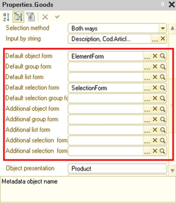
Fig. 141. Choice parameter links
Values specified in this property will be transferred to the opened form via the Parameters structure (see Form parameters). The Name column value will correspond to the structure element key, and the attribute value stated in Attribute column to corresponds to the structure element value. If the Name column includes the Filter.Owner-type value, the Filter form parameter will be created (Structure type). In this structure, the item will be created with Code key and the value received from attribute specified in Attribute column (in the example – Provider).
If the name of some Choice parameter links property element is the same as name of some Choice parameters property element (see Choice parameters), the priority is given to the element from Choice parameter links property in case the value of the field specified in Choice parameter links element and sent to ValueIsFilled() function returns True. The element from Choice parameters property is ignored.
Also, you can set the of field clearing when changing link fields in the choice parameter links editing window. If the value of Linked value change mode property is Clear, the field will be cleared during the interactive changing of link value (the repeated choice of the value already present in the field is also considered changing) before the OnChange event has occurred. Otherwise (the property value is Do not change), the field will not be cleared. The clearing happens regardless of the actual value change in the link element and is made before calling the OnChange event handler.
If the field displays the table data (table columns or separate field connected to the current data), the clearing of such field is made is the data source of the form table is FormDataCollection or FormDataStructureAndCollection. If the attribute that requires clearing is connected to the table data and the link attribute is not a piece of the table data, the values in all rows with the attribute, for which choice parameter links are set, is made. The attribute cannot be cleared if it is connected to the DynamicList-type attribute column.
For the standard Parent attribute of the subordinate catalog, the situation is possible, where the Choice parameter links property will be changed automatically by 1C:Enterprise. This change happens in the following cases:
-
When the catalog changes subordination status.
-
When the Hierarchical catalog property of the catalog is changed.
This change happens in the following way:
-
If the catalog is subordinate and hierarchical, then for the Parent attribute the Choice parameter links property is supplemented with the following parameter: Name: Filter.Owner – Attribute: Owner.
-
Otherwise, the Name: Filter.Owner – Attribute: Owner parameter is property is deleted from the Choice parameter links property parameters of the standard Parent attribute.
Let us consider an example: a form contains the Vendor field and the VendorCurrentAccount field. For the ProviderCurrentAccount field, the ChoiceParameterLinks property is set to Object.Provider value, which will be set in the Owner filter field.
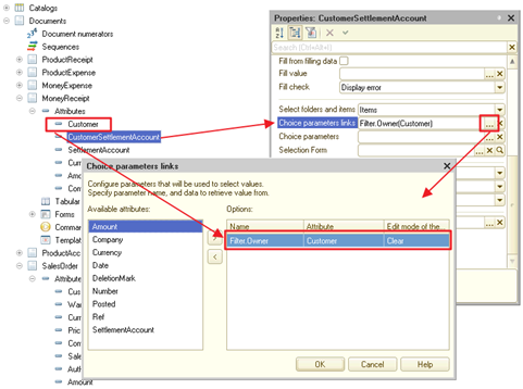
Fig. 142. Clearing connected form items
Then when changing Provider field value interactively, the ProviderCurrentAccount field will be cleared automatically.
5.6.19. Choice parameters
Choice parameters. This property allows setting the parameter values, which will be used when choosing the attribute value. Choice parameters will be performed when opening the choice form, when displaying the quick choice list and when inputting by rows. For example, the choice has to be limited by the goods with Type attribute equal to Enumeration.GoodTypes.Service value. The values list can be specified for the specific filter. To do this, choose Fixed array type when editing the Value column.
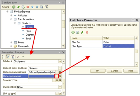
Fig. 143. Choice parameters
Values specified in this property will be transferred to the opened form via the Parameters structure. The Name column value will correspond to the structure element key, and the Value column corresponds to the structure element value. If the Name column includes the Filter.Code-type value, the Filter form parameter will be created (Structure type). The item with Code key and Value value will be created in this structure.
If some parameter name of the Choice parameter links property corresponds to the name of some parameter of Choice parameters property, the priority is given to the element in Choice parameter links property (the parameter from Choice parameters property is ignored). The priority will be given in case the value of the field, specified in Attribute parameter of the Choice parameter links property is filled (ValueIsFilled() function for this value returns True value).
Note. Note. Values stated in the Choice parameters attribute property are also used by the dynamic list and data composition system.
When choosing an extra dimension value in the cell of the table connected to the accounting register record set, the choice parameter for Owner field is only set automatically if this type of extra dimension has the catalog type of the extra dimension additional values. The value of choice parameter is the correspondent extra dimension type.
5.6.20. Other
The Use standard commands property defines the ability to include standard commands (for example, catalog list opening commands) of this object into a command interface. If the value of the property is False, the standard commands will not be displayed by 1C:Enterprise and you can only include the object into the interface using the command created in the Designer.
The Choice form property defines the form that will be used to choose the attribute value. Used for the attributes with the types created by the metadata object that has the form concept. For example, the Goods catalog has several choice forms and for the standard Parent attribute the special form must be used. To implement such behavior, this special form must be specified in the Choice form property of the standard Parent attribute (for standard attribute details, see Standard attributes).
Format for Number, Boolean, and Date types allows setting the format of data display on output.
Editing format. The property that allows setting the format for editing the data of Number, Boolean, and Date types.
Type link established connection with the attribute, limiting the type of values input for the input field. Setting the link by type is reasonable for the attributes with the compound data type that are logically connected with another ChartOfCharacteristicTypes.Link-type attribute, including connection with the attribute containing extra dimension with the attribute, containing values of Link to chart of accounts type. Link by type item contains the number of extra dimension type in case the attribute, which is linked by type, has the values of Link to chart of accounts type.
For example, there are two attributes: CharacteristicType and Characteristic. The CharacteristicType attribute has the ChartOfCharacteristicTypesGoodsCharacteristicTypes.Ref type. The Characteristic attribute has the Characteristic.ItemCharacteristics type. The Type link – CharacteristicType attribute can be set in the Characteristic attribute properties. In this case the type of the value chosen will be defined by the type, set for the chosen chart of characteristic types value.
5.7. Constants
5.7.1. General information
The 1C:Enterprise constants are designed to store persistent or conditionally persistent information. Such information is not changed at all during the business operation or changed rarely. The simplest example of such information is the company name, which, as a rule, does not change.
The main reason for using the constants is to write some information to a constant and then repeatedly use it in documents, calculations, and reports. The constant value can be edited from time to time.
Let us look at the example. Corporate documents often include CEO and chief accountant signatures. Naturally, these employees must be the ones that use their signatures. However, in addition to the signature, the documents require the last name of the signer of the document. Of course, names of CEO and chief accountant can be added directly to the document forms. But some name can change and then you will have to edit all form and change names all over again. This is why, it is much easier to create two constants in configuration, for storing names of CEO and chief accountant to enter the names into constant once and then use constant names to get their values. When changing the CEO or chief accountant, simply enter new names and all changes will be automatically applied to where the constants are used.
Note. IMPORTANT. When changing the constant value, the previous value is lost. To get previous values instead of the constant, use information register without changes.
1C:Enterprise Designer allows you to create almost infinite number of constants for storing any information.
5.7.2. Constant properties
The Constants branch of the configuration tree is designed for operating constants.
The constant properties are edited in the property palette. Please note that constant is the typified configuration object.
Type describes the constant type. The constant type can be any of the standard configuration types (Date, Number, CatalogRef, DocumentRef and so on) or compound (consisting of several types).
Depending on the chosen type, the property palette may include additional properties specifying the type chosen.
If the constant editing form has to be displayed in the command interface, set the Use standard commands property. In this case the command for opening constant editor will be displayed in subsystems, to which the constant belongs. The constant editing form is set using the Main form property (for details, see Constant form wizard features).
The forms for constant input are created in the General forms branch.
5.8. Catalogs
5.8.1. General information
When filling a document form, you might often require to specify the information by selecting it from the list.
Let us take the job application form as an example.
When filling the Place of birth row, specify the city. The total number of cities is quite large, but the list of cities is limited. In fact, the place of birth can be specified by choosing from such list. This list is the catalog.
Thus, the catalog is the list of possible values of this or that document attribute (document in general).
The catalogs are used to prevent the unambiguous input of information.
For example, to ensure that the customer, sales manager, storekeeper and director understand what good are they talking about. Everyone has to call it concisely. The catalog is needed in this case. In commerce, it is usually a price list. If such catalog is stored on the computer, all products and services that the company sells if included into the list.
1C:Enterprise allows keeping practically unlimited number of catalogs. Each catalog is a list of object instances of the same kind: employees, companies, goods, and so on. Each object instance will be called the catalog item.
Keep in mind that the catalog structure is created in the configuration and its content itself – catalog items – is entered by the users. When configuring, the structure of information to be stored in the catalog is described, the desktop and, if needed, the print presentation of the catalog is developed, and various behavior traits are set.
As a rule, catalogs has the standard attributes, code, and name. Code can have Number or Row type.
1C:Enterprise provides various features for operations with catalog item codes: automated code assignment, automated uniqueness control, and others.
The 1C:Enterprise catalog can be hierarchical. There are two types of list hierarchy: Folder and item hierarchy and Item hierarchy. In the first case, all catalog data will be divided into two kinds: separate catalog items and catalog folders. Folders are a logic combination of the catalog items. The example of hierarchical catalog is the goods catalog where the folders are types of goods (Sanitaryware, Household chemical goods and so on) and items are specific goods (Mixer, Mirror, Detergent).
Hierarchical catalogs allow you to organize information input into the catalog with the required level of detail. Items and folders in the hierarchical catalog can be transferred between groups.
For catalogs of the Hierarchy of items type, there are no folders as a separate type. The items themselves play their role. The distinctive feature of such catalogs is functionality of all elements. The example of such catalog is departments catalog. Each department is described with the same set of attributes and it can logically contain another department or be the part of some department.
For the hierarchical catalogs, the Designer allows setting the limit on the number of catalog levels. The unlimited levels of nesting are allowed, too.
Apart from code and name, the set of attributes for storing additional information on the catalog item can be created.
For example, the Contractors catalog may contain such data as the full contractor name, tax ID, CEO and chief accountant last name and other information.
If the object of the subject domain corresponding to the catalog has simple properties (for example, a full name or a tax ID) and complex (list) properties, you can create a set of tables for the catalog.
For example, in the Counterparties catalog, you can create a table for counterparties' phone numbers.
Attribute names cannot match any attribute names from a table.
To operate the information in the catalog, a screen form can be created. Separate form can be created to view the catalog list items, edit catalog items, choose the required item from the catalog.
Designer allows creating several forms of the same type, for example, a form to select a catalog item, and using different forms in different cases.
It is recommended to create different forms for displaying item list and choosing catalog items.
5.8.2. Catalog properties
The Catalogs branch of the configuration tree is designed for working with the catalogs.
When creating the new catalog, an object editing window opens (see Object editing window).
Hierarchical catalog. If the property is set, the catalog has hierarchical structure and Hierarchy type and Limit of hierarchy levels properties become available.
Hierarchy type. The type of hierarchy in this catalog is defined. If you select the Folder and item hierarchy type, the catalog will contain items of two kinds: folders and items. The folders combine other groups and catalog items. Usually, code, name, and parent (link to the higher level) is enough to describe a folder. The catalog item might include other attributes, specified on the Data tab. For the catalogs with this hierarchy type, folder forms and item forms can be created. When choosing the Hierarchy of items type, all items in the catalog are equal. The example of such catalog is the department catalog and heads of expenditures.
If the Folder and item hierarchy type is set for the catalog, then when creating an item or folder form, the form elements connected to the attributes belonging to the item and folder can be located on the form (no restrictions). The form will allow editing data without checking the usage option set for the attribute. When writing an object, only data of its usage option will be written: for an item form, item attributes and common attributes will be written, for a folder – folder attributes and common attributes. No error messages are displayed in this case. When opening the form again, the form elements, connected to "other" attributes will be filled with the default values.
Place folders on top. The value is available when the Folder and item hierarchy value is set. If the Place folder on top property is set, when you display the catalog as a hierarchical list, the folders will be located on the top of the list and items will be located below. If the property is not set, the location of folders and items will follow the set sorting rules (by code, by name and so on). For example, when creating a new folder with the code that is bigger than all other folders and items (when sorting by code), if the first case this sub-folder will be lower in the list but higher than other catalog items. In the second case, it will be located in the lowest row.
Note that setting and unsetting the Place folders on top property does not affect the catalog view in non-hierarchical list.
Number of hierarchy levels. The property is available if the Limit of hierarchy levels property is set. The catalogs in 1C:Enterprise can have more than one nesting level. If the Limit of hierarchy levels property is not set, the maximum number of nesting levels is not limited.
Owners. This property required a detailed description.
Any catalog can be used by itself or it can be subordinate to some other catalog or catalogs. For example, the contracts catalog can be used separately of it can be connected to the organizations catalog.
To subordinate the catalog to another one that already exists in 1C:Enterprise, click the editing button in the Owners list field and check the catalogs that are owners of the current catalog in the object choice window opened. Such catalogs are called owners in 1C:Enterprise, and the catalog itself is the subordinate.
Unlike the multi-level catalog where all items have the same structure, using the subordinate catalog feature allows you to connect items with different structure. In this case each item of the subordinate catalog will be logically connected to one of the owner catalog items.
For catalogs with several owners, different items can have the owners of different types, but one item can only have one owner.
If the catalog is subordinate (at least one value is specified in the Owner list field), for the standard Owner attribute, you can select how the system will process shrinking the list of owners for this catalog. This behavior is defined by the Type shrinking mode property of the standard Owner attribute:
| Value | Description |
|---|---|
| Deny | Restructuring will be locked if the infobase contains catalog items for which the Owner attribute is set to the value of the type to delete. |
| Convert values | During restructuring, the value of the Owner attribute will be set to Undefined for those catalog records that were subordinate to values of the type to be deleted. Once restructuring is completed, you will be able to find all items that have the Owner attribute filled with the Undefined value and link them to a value of a different type. |
| Delete data | All records that were subordinate to values of the type to be deleted will be deleted from the catalog. You can set this mode when data in a subordinate catalog makes sense only "together" with its owner. |
Using subordination allows you to manage limits applied to the owner. Possible use modes: only items, only folders, both items and folders. If a catalog has several owners, the limit is applied to all owners.
Code length. The property sets the maximum length of the catalog item code.
Designer allows you to set the code length to 0. This will be handy in case the catalog item code is not used.
When assigning this property, it is recommended to define the real code length. However, remember that when operating the configuration, the code length can be extended, if required.
Note. Note. The maximum code length is 50.
Name length. The maximum length of the catalog item name is set in the property.
Designer allows you to set the name length to 0. This means the catalog will not have a name.
Note. Note. The maximum name length is 150.
Code series. The property allows setting the code uniqueness checking range and automated code assignment.
If the In the entire catalog setting is chosen, when the code is assigned automatically or when the user enters it manually, the code uniqueness will be checked among all catalog items.
Setting Within subordination area setting is only true for hierarchical and subordinate catalogs. In this case the code uniqueness will be checked by 1C:Enterprise within the folder and the item of owner catalog, to which the new catalog item is entered or where the existing item is edited.
When setting Within subordination area, catalog items in different groups can have the same codes. This must be considered if you need to transfer items of multilevel catalog between folders. When the code of the transferred item corresponds to the code of the existing item the warning will be displayed and the item will not be transferred.
When setting a code series to Within subordination area, the owner in the hierarchical subordinate catalogs is provided with the automated numbering and code uniqueness control among the items with the same owner but different parents.
Code type. The property allows you to select a value type for the catalog item code: Number or String. Choosing the code string type can be handy when the complex coding system is used and when the code includes letters and separators apart from digits. The most representative example is using markings of clothes as codes.
Note that selecting a code string type does not exclude automated assignment of such codes.
For the first item 1C:Enterprise generates code that looks like 001 (a number of zeros depends on the maximum code length), meaning that the code is the characters line, but all characters are digits. When entering other catalog items, 1C:Enterprise will keep assigning the codes in a similar way: 002, 003, and so on.
If the catalog keeping requirements include using digits and letters in codes, then for automated numbering the codes can be used that look like: AA001. The first part of the code is AA characters which are text prefix, and the second part is 001 characters will be interpreted by 1C:Enterprise as a digit. It will then be used when assigning the next code automatically.
For example, if the first code in the catalog is AA001, the next automatically assigned code will be AA002, then AA003, and so on with increments.
The text prefix can be set manually (enter such "compound" code when entering a new item in 1C:Enterprise) or you can use prefix setting features of 1C:Enterprise language (the SetNewCode() method).
Code allowed length is also available when the Code type property is set to Row. This property can be used to regulate the length of the row that will store the code. If the value is Fixed, the length of the row with the catalog item code will always equal the value in the Code length property. Otherwise, the row length equals the number of characters in the item code.
Attributes. Any new catalog can be presented as a table with two columns: catalog item code and catalog item name. 1C:Enterprise allows storing additional information about the catalog item, apart from code and name. When editing the catalogs, you can describe the set of additional attributes designed to store such additional data.
When displaying the catalog on the screen, the attributes can be presented as table columns of the catalog list form. Moreover, the data stored in attributes can be used when generating in calculations, when generating reports and so on.
You can use the catalog attribute feature to easily organize employee files, for example. To do this, create attributes to store data on education, ID and other HR information in the Employees catalog. The required employee information can easily be found with the native search tools in the catalog when using the configuration.
Tables. To describe some data related to the catalog and not used independently, use tables. An example of a table is an employee's employment sheet or a list of employee's family members. In the second case, data on each family member is described in table attributes and the number of members can be arbitrary.
If the data on the employee family members can be used separately, such data could be included into the separate catalog, which would be subordinate to the Employees catalog.
The main difference between a table and a subordinate catalog is that catalog items can be referred to and table rows cannot be referred to. When accessing a catalog item, the whole catalog with all tables is read and goes from the database to the memory. If a table contains a large number of rows, this might impact the performance. This is why, use tables if you do not need to store references to items and the number of items is limited. Each catalog can have the unlimited number of tables.
Autonumbering. If you select this checkbox, the 1C:Enterprise will assign the codes to the new catalog items when writing. Users can edit automatically assigned codes.
Uniqueness check. If the code is used for the unambiguous identification of the specific catalog item, it must be unique (it must not be repeated). If the Uniqueness check property is set, the code uniqueness check will be performed automatically when entering new catalog item.
Default presentation. The property sets the catalog items presentation. For example, the values of CatalogRef type, entered into the attribute of the document/catalog or constant, will be presented as a code or catalog item name, depending on this property. For the list forms, this column becomes the default one. When opening the list this column becomes active.
Generation. On the Generation tab you specify, which configuration objects could be used as a basis for objects of this type and which objects could use the objects of this type as a basis. When clicking Generation settings wizard you start the generation procedure wizard. For details on how to use the wizard, see Generation settings wizard.
The example of generation is inputting Release for sale document based on the Goods catalog.
5.8.3. Catalog attributes properties
The catalog has the following properties apart from the main ones:
-
Type describes the attribute data type.
-
Usage defines the usage of attribute for folders and items in the hierarchical catalog.
5.8.4. Predefined catalog items
The configuration developer can create a set of predefined items and folders for the hierarchical catalogs. For details on predefined items, see Predefined data.
Note. IMPORTANT. Predefined items cannot be created for a catalog with an owner. And vice versa, an owner cannot be assigned to a catalog with predefined items.
5.9. Documents
5.9.1. General information
Document is one of the main concepts in 1C:Enterprise. Documents are used to organize input of data on the business operations.
In most cases documents created during the task configuration setting are digital equivalents of the standard paper documents; however, this type of data has much more possible usage scenarios than the business standard data registration.
Each document contains information on the specific business operation and is characterized by number, date and time. Date and time are the most important characteristics of the document, as they allow you to define the specific sequence of actions with timing.
Configuration only includes description of document structure and the specific document instances are entered by the user during operation. For example, in 1C:Enterprise, the Invoice document created during configuration will allow creating invoices with different content but the same set of attributes, behavior logic, and so on.
To simplify, further in the document, the "document structure" will be replaced with "document" to describe means of document input and visualization.
Designer allows you to describe the document structure, organize forms for data input, and describe the algorithm for building print forms.
Apart from date, time and number, you can create a set of attributes for storing additional information.
If the object of the subject domain corresponding to the document has simple properties (for example a date, a number, and total amount) and complex (list) properties, you can create a set of tables for the document. For example, in the Expenditure invoice document, you can create a table for the list of products or services sold.
To work with the documents in configuration you can create the required number of document lists of the same type and document journals of different types. The list form is different from the journal form. First of all, the list does not include the Document type column (because the list consists of a document with the same type), and the journal usually has such column.
When creating the document you can specify the list of journals, in which the documents of this type will be operated. For documents of different types, you can specify one journal. It allows you to customize document groups in journals. The journals assigned to the document can be changed.
The documents can change register state (posting). If the document is posted, the data entered by the user, are displayed in the system registers: goods balance has changed, debt to the contractor has changed and so on. The documents can be posted in real time (real-time posting) or with the past date (non-real-time posting).
5.9.2. Document properties
The Documents branch of the configuration tree is designed for operating documents. The configuration service objects (numerators and sequences) are located on the same branch.
This section includes description of specific document properties that are different from the general configuration object properties.
The document properties are edited in the property palette or editing window (see Object editing window). The document data in the editor window are divided into tabs.
The Main tab includes the main document data.
The Data tab displays attributes and tables.
The property palette includes main attribute properties and type of each attribute. For fast search or filtering by attributes, the Index property must be set for the attributes (for details, see Indexing object attributes).
The Numbering tab includes data used to assign document numbering rules.
Each document has the required attributes that are created automatically and cannot be deleted. These are time, date, and document number. Unlike date and time, there are several parameters that can be set for the number. These parameters will control behavior of the attribute when operating the document of the created type. The combination if these parameters will define the document numbering rules in 1C:Enterprise.
Autonumbering. If you select this checkbox, 1C:Enterprise automatically assigns a new document number. Users can edit automatically assigned numbers.
Numerator. A numerator can be assigned to the document. To assign the document with the numerator, select in the Numerator property. In this case, other elements for describing numbering rules, except for the Autonumbering property, become unavailable. It means that rules for numbering documents of this type will be completely defined by the assigned numerator. For details on creating numerators and their properties, see Numerators.
Using numerators allows you to organize the consecutive numbering for different document types. To enable this, assign the same numerator to all documents that require the consecutive numbering During uniqueness control and assignment of the next number, all documents with this numerator assigned will be considered.
Number length sets the maximum length of the document number.
Number type. The property is similar to Code type property of the catalog (see Catalogs).
Number allowed length is also available when the Number type property is set to String. This property can be used to regulate the length of the row that will store the number. If the value is Fixed, the length of row with the document number will always equal the value in Number length property. Otherwise, the row length equals the number of characters in the document number.
Uniqueness check. If the device is installed, then when the new property is set, is number is checked for uniqueness in the range specified in Periodicity.
Periodicity. The property sets the limits for document number uniqueness control and period of number repeatability. If the Uniqueness control property for the document numbers is set, the range of control must be specified in the Periodicity property.
When the Autonumbering property is set the 1C:Enterprise will assign the next number to each new document. After the period set in Periodicity property is expired, the documents numbering will start from 1.
The Register records tab includes behavior settings when posting the document and unposting.
Posting. The value defines whether the document posting is available when writing. If you choose Allow, the document will make register records (change their state). Another consequence of this choice is automated calling of Posting event handler for document posting in 1C:Enterprise mode that is enabled when clicking the button of the document form, for which the Save and close predefined action is set during configuration (usually the button is OK). To create the Posting event handler, you can use the register record wizard (see Register record wizard). Its call button is located on the Register records tab of the Document object editing window.
Real-time posting. The property defines whether real-time posting is allowed for the document. For documents with the allowed real-time behavior, when you choose the date other than the current, the document is posted in non-real-time mode, because the fact is already happened and no control is required unlike in real-time mode (for example, verifying the balance, specified in the expenditure invoice of the good).
If the Real-time posting is allowed for the document, the document is created with "null" time. When posting, 1C:Enterprise gets the current time stamp, which can correspond to current date and time, but it can also be more than the current time. The document is assigned with the time stamp and then the real-time posting is performed. For more information about a real-time timestamp, see Real-time timestamp.
In case the document with the set Real-time posting property is edited, the time is different from the current, meaning that when posting (current date is specified) the request for posting type is displayed. If you choose Real-time posting, the document will be assigned with the current time. If you change the time when editing (for example, specify the future time of the current day), 1C:Enterprise will also set the current time. If you choose Non-real-time posting as a posting type, then when the date format does not offer time input, the time of day beginning is specified in the document.
Register records deletion. The property is available if the Posting property is set to Allow. In case of repeated posting or unposting it defines the deletion mode for all records that the document wrote during posting:
-
The Auto delete mode means that the deletion is performed by 1C:Enterprise while posting the already posted document (before writing new register records) and while unposting.
-
The Auto delete off mode means that the register records are deleted programmatically under special conditions. This mode is used when you need to control deletion while posting or unposting.
-
The Auto delete on unpost mode means that 1C:Enterprise will automatically delete register records only when unposting. The register records will not be deleted during the repeated posting. This mode is set by default.
If the Register records deletion document property is set to Do not delete automatically or Delete automatically on clearing posting, then to avoid data duplication, clear the Records collection when proceeding to post.
Register records writing on post. The property defines system behavior when creating register records during document posting:
-
The Write selected mode (the default mode) means that the register records collection will only be written if the Write set property is set to True (regardless of the modifications in records).
-
The Write modified mode (set during conversion from 1C:Enterprise 8.1 and earlier versions) means that only modified record sets will be written (the 1C:Enterprise will automatically set the Write property to True).
After the document is written, the 1C:Enterprise set the Write property of all record sets registering document register records to the default one, even if the writing was unsuccessful.
Sequence filling. The mode of automated sequence filling is chosen. In the editing window on the Sequences tab, the occurrence of the document in a sequence.
In the document editing window of the Journals tab, you can mark document journals, in which the documents of this type will be displayed when user operates 1C:Enterprise. The required document journal form can be created later.
The Generation tab includes two lists of configuration objects. In the top list, specify the objects used as a basis for document generation, and in the lowest, specify which objects will use this document as a basis when generating.
Note. IMPORTANT. The document can be generated based on other document or the object of different type (catalog items, chart of characteristic types, chart of accounts, and chart of calculation types). And vice versa, the document can be used as a basis for generation of other document or object of different type.
To create the procedure that prepares source data for object generation, use a special wizard. For its description, see Generation settings wizard.
On the Rights tab you can set the privilege mode of posting (Post in privileged mode property) and/or unposting (Unpost in privileged mode property):
-
If the property is set, the corresponding action (posting or unposting) will always be performed by 1C:Enterprise in the privileged mode (when calling posting or unposting on the server side and in file mode). However, the privileged mode will not be set if the posting (or unposting) of the document is performed in client/server mode on the thick client side. The following is performed in privileged mode:
-
Automated register records deletion.
-
Automated register records writing.
-
The handler (Posting or UndoPosting). However, the object writing is performed in the ordinary (non-privileged) mode.
-
-
The privileged mode is enabled by the system after the object is written before posting (before deleting register records in case they are deleted automatically). The same applies to unposting.
-
When creating new documents, the properties are set to True, if the default run mode, managed application, is set in the configuration properties, and False, if the startup mode is ordinary.
5.9.3. Document posting feature
The information on business operations is stored in registers (see Registers). Documents can change register state. Such process is called posting. This feature is a recommended method for changing the register state. The posting is performed in real-time and non-real-time mode (Real-time posting property).
Note. Note. As a rule, the real-time posting feature is used for the current accounting.
5.9.3.1. Real-time and non-real-time posting
The real-time posting feature is designed to separate cases when a document is posted in real time and cases when document posting registers something that already happened.
The real-time posting is required when the input and posting do not just register the event but take part in its creation and help the operator to input the information correctly. Of course, it only makes sense when the event is happening in real time.
The classic example is inputting and posting the document describing the sale of goods from the warehouse. When inputting such document, the operator's task is not to simply enter the list of goods sold to the customer correctly but to perform various checks. First of all, the operator must check, whether the product is in stock in the specified warehouse. Remember that several operators work at the same time and they might write out the same goods. The 1C:Enterprise task is to avoid selling the same thing to different customers. Besides, checking the loan available for the customer and verifying payment might be required as well as many other types of checks.
At the same time, if the document is entered with the past date, that is it is known that the business event has already happened, for example, the specific product is already shipped to the customer, such checks are not required and you only need to register the event. In this case, posting the document registers the event and does not take part in its creation.
So, the task of the real-time posting feature is to separate two posting modes: from the user's perspective, so that they can understand which type of posting is performed; and from the algorithm perspective, so that it can perform actions in accordance with the current posting mode.
The document posting mode is identified by the date. If the posted document date corresponds to the current date, the 1C:Enterprise will post such document in real-time mode without additional requests and you can learn it from the behavior processing to build the specific algorithm of document posting.
5.9.3.2. Form extension and posting
Apart from the Real-time posting document property, there is a way to set the posting mode for the document form extension. The Use posting mode property can have the following values:
-
Non-real-time. The document will be posted in non-real-time mode. If there are not enough rights for non-real-time posting, the exception will be displayed.
-
Real-time. The document will be posted in real-time mode. If there are not enough rights for non-real-time posting, the exception will be displayed upon the attempt to post a document with the past date.
-
Auto. In this case, 1C:Enterprise follows the algorithm:
-
If the document date is earlier than the current date, the non-real-time posting is performed.
-
If the document date is the same as the current date, the real-time posting is performed.
-
If the document date is later than the current date, the exception is displayed.
-
If the document cannot be posted in the chosen mode (not enough rights and so on), the exception will be thrown, too.
-
If the posting mode is unknown on the client side, the Undefined value will be set to PostingMode parameter of the BeforeWrite event handler.
-
One of the objectives of real-time posting of documents is placing them chronologically on the timescale. Such placement is required, in particular, to write the balances off correctly in the balances register (see Balance registers and turnover registers) of the current accounting. To place the documents, we use such terms as point in time and current timestamp. Let us have a closer look at these terms.
To identify the document location of the time axis, the Date document attribute is used, which contains accurate time to seconds. This allows you to control the document writing sequence. However, when large volumes of documents are created, several documents might have the same date value (that is they were created within a second). How to define the sequence of created documents in this case?
5.9.3.3. Point in time
To handle such situations, there is such term as point in time. The point in time is a combination of date, time and link to database object. It allows you to unambiguously identify any reference object of the database on the event axis, but it only makes sense for documents. Besides, the point in time allows you to identify non-object data, for example, register records subordinate to the register.
The concept of point in time is implemented in 1C:Enterprise language using the PointInTime universal object.
The sequence of several documents, which have the same date and time, on the events axis is defined by the system based on the links to these documents. It may not match the document creation sequence, and it is unavailable for editing by the user. It means that you cannot control the document sequence within the second or identify that one document was created earlier, and another one was created later.
5.9.3.4. Real-time timestamp
Real-time timestamp is the Date type value. The current timestamp is a "basis" which enables real-time posting. The current time-frame is created by the system each time the document is posted. Its value is based on the current session date and the last created current timestamp.
5.9.3.5. Zone time
When operating the system from different time zones, consider this fact when getting the current timestamp. For example, the single database located in one city (time zone) might be used for accounting at several enterprises (for example, branches of a holding), which are located in other cities (and other time zones). In this case each branch needs the separate timestamp.
To account in new time zones, there are concepts of infobase time zone and session time zone.
Infobase time zone defines time zone set for new session by default. When the infobase is created the time zone is not defined. However, it can be set using the SetInfoBaseTimeZone() global context method. Information about the infobase time zone is saved to the database and does not change with the infobase dump and restoration operations. When creating the initial infobase image (using distributed infobase mechanisms, see Distributed infobases), the infobase time zone, in which the image is created, is transferred to the image created.
If the infobase time zone is not set, the time zone of a computer with 1C:Enterprise server is used (in client/server mode) or the local computer time zone is used (in file mode).
Session time zone describes the time zone, in which the specific session runs. By default, the session time zone is the same as infobase time zone.
The session time zone can be set using the SetSessionTimeZone() global context method. The session time zone is saved until the end of the session. It is used to determine the current session date and the current timestamp.
5.9.3.6. Getting current timestamp
During real-time posting, the 1C:Enterprise changes the document time to ensure that the next document posted in real-time mode has the later point in time than the previous document posted in real time. The current timestamp concept is used for this. The 1C:Enterprise gets the current timestamp automatically during real-time posting, but it can also be received explicitly in 1C:Enterprise language using GetRealTimeTimestamp() method based on the current session date.
Current session date is equal to the computer date modified to comply with the session time zone. Modification means converting the local computer time to the zone time set by the session time zone. The time is converted through universal coordinated time (UTC).
All users access the same current timestamp functionality, and it issues a new timestamp for each user. The current timestamp functionality provides a date that is later than the previous timestamp received by this or another user in this time zone. As a rule, 1C:Enterprise returns the current session time as a timestamp. However, if the current time is greater than or equal to the latest issued timestamp, the functionality returns a value that is one second larger than the latest issued timestamp. Thus, upon access the user receives the value that might correspond to the current time but is always more than the previous issued value.
Remember that different sessions within the same time zone will use the same time to get the current timestamp. There will be as much separate current timestamps as the unique time zones set as the session time zones.
5.9.4. Numerators
5.9.4.1. General information
Number generator is a configuration object that describes document numbering rules: document number type and length, its periodicity, and the need for uniqueness control.
The main purpose of a numerator is to provide consecutive numbering of documents with different types. The same numerator is set for the documents to enable this.
5.9.4.2. Managing numerators list
To operate configuration objects of Numerator type, there is a configuration three branch, which is located within the Documents branch and starts with the Numerators keyword.
5.9.4.3. Numerator properties
This section includes description of specific numerator properties that are different from the general configuration object properties.
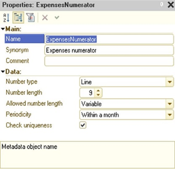
Fig. 144. Numerator properties
Number type is that value type for a document number: digits or text. Choosing the text type can be handy when the complex document numbering is used and when the number may include letters and separators apart from digits.
Number length sets the maximum length of the document number.
Periodicity. The property sets two important number generator characteristics: limits for document number uniqueness control and period of number repeatability.
If the Uniqueness control property for the document numbers is set, the Periodicity property sets the limits for such control.
For example, if periodicity is set to Day, the uniqueness of document numbers will be controlled within one day. Document numbers can be duplicated the next day, but they will be unique within one day.
When the Autonumbering property (see
Document properties) is set, the 1C:Enterprise will assign the next number to each new document. After the period set in Periodicity property is expired, the documents numbering will start from 1.
Uniqueness check. If the device is installed, then when the new property is set, is number is checked for uniqueness in the range specified in Periodicity.
5.9.5. Document sequences
5.9.5.1. General information
The document sequences are auxiliary configuration objects. They enable posting of specific documents with a strict chronological order.
All documents in the 1C:Enterprise form a single chronological sequence. Each document has a date and time. Even if two documents have the same date and the same time, they are still arranged in a sequence, determined by the time of their entry into the system. Document date and time are subject to change. Thus, regardless of the order of entry, documents can be arranged in a sequence that reflects the actual order of events that occurred in the economic life of the company and that are described in the documents.
During posting, a 1C:Enterprise document performs actions that are registered, by this document, in several accounting systems supported by 1C:Enterprise.
The algorithm of document posting, as a rule, reflects data recorded in the document (its attributes and tables). However, in some situations, the document posting algorithm also analyzes and uses the current totals. For example, if a document writes off goods or materials at average cost, the posting algorithm will analyze the balances of goods (materials) at the time of the document in order to determine the write-off amount. If the write-off is performed using LIFO or FIFO methods, the posting algorithm will analyze the existing balances of goods (materials) broken down by lots at the document time, defined by the document posting date and time.
Obviously, documents that use these totals should be posted in strict sequential order. However, in practice, it is often necessary to back-enter or back-correct the documents due to data input errors and late receipt of documents. Back-entering or back-correcting a document invalidates all register records generated by the documents following this one. For example, if it became clear that the quantity of goods was incorrectly indicated in one of the incoming invoices at the beginning of the month, then in all subsequent expenditure invoices writing off existing lots, it is necessary to re-analyze the balances considering the changes made and re-record movements of the registers. Therefore, all documents that analyze the balances following the corrected document must be reposted.
In case the infobase, in which the sequences are used, is included into distributed infobase, it's recommended to include document sequences, which include documents sequences with automated sequence filling enabled, into exchange plans. Otherwise, there might be an unlimited data exchange and document reposting.
For automatic control of document reposting, objects from Sequences branch are used. Each Sequence object entered into configuration provides control over the document posting of the specified types. Thus, there may be several independent sequences in 1C:Enterprise.
5.9.5.2. Managing sequences list
The Sequence-type objects are created in Configuration window. There is a separate configuration tree branch for sequences, which is located "inside" the Documents branch and starts with Sequences keyword.
5.9.5.3. Document sequence properties
This section includes description of specific document sequence properties that are different from the general configuration object properties.
The sequences properties are edited in Sequence editing window.
On the Usage tab, you can select documents, related to this sequence, and register records affecting the sequence.
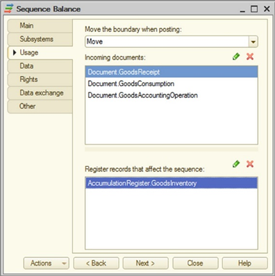
Fig. 145. Sequence properties
Move boundary on posting. If the Move value is set for the property, the document registered in this sequence will try to move the boundary of this document sequence when this document is posted. If the Do not move value is set for the property, the document will not try to move the boundary of this document sequence when this document is posted.
Incoming documents. In the upper list of the Sequence window, the types of documents related to this sequence are specified.
Choose the types of documents that will analyze the register state when posted as the ones that will be affected by the sequence. Such documents may include invoices, transfer note, release note, sales note and so on.
Register records affecting sequence is one of the main sequence properties. It defines which register records will affect the need to repost documents in this sequence, that is, which register records and totals of which accounting features are used by the documents in this sequence when posting. For example, registers can be such register records.
To customize the parameter, add register types, which will break this sequence by their register records, to the list.
Dimensions. Sequences can have the subordinate objects called dimensions. They are created on the Data tab of the editing window.
In case there are no dimensions created for the sequence, all incoming documents will be reposted when this sequence is restored. If you need the sequence to account the specific situation, not all of them, the dimension should be included into the sequence. In this case, only those documents that change the register state with regard to the dimension properties will require reposting.
If the state of registers in the sequence changes, the later documents with the same values in attributes (listed in the Conformity with document attributes dimension property) that are included into the attributes of deleted (added) register records (listed in Conformity with register record attributes dimension property) become irrelevant.
For example, the sequence account changes in the register state for Arrival invoice and Expenditure invoice documents. In case there are additional criteria of the need to repost the specified documents must be considered (for example, the documents must be reposted by the specific product or service value), the dimension must be added into the sequence. Its type must be specified in a property palette of the dimension (CatalogRef.Products) and connection with the register attributes must be set.
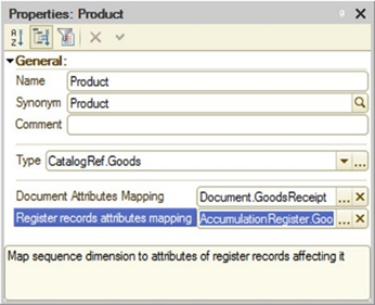
Fig. 146. Sequence dimension properties
According to the chosen dimension type, the dimension document and register lists to choose from only include those object that comprise dimensions of the specified type.
Entering the dimension allows you to reduce time of document reposting. It is particularly important when there is a large number of documents as only documents that contain data of the specified dimension value will be reposted.
5.9.5.4. Operating document sequences
When operating in the 1C:Enterprise mode, the 1C:Enterprise will automatically maintain the boundary of each document sequence entered into configuration. This sequence boundary is the point in time, which is the date from the document itself. When posting the documents from the sequence sequentially, the sequence boundary will be set at the point in time of each document posted. However, when the document included into the sequence but created later than that already posted document from the same sequence is posted later than the sequence boundary, the sequence boundary will not be shifted, because the document posting sequence will be corrupted. The document posting algorithm can analyze this situation.
When posting the documents with their past date, unposting or deleting documents, when register records are deleted specified as affecting this sequence are deleted or written, the sequence boundary is moved to the point in time of the changed document. Before moving the boundary backwards, the 1C:Enterprise verifies that there are borders to move. Such verification is performed without exclusive boundary locking.
Thus, the sequence boundary will move forward with the sequential posting of the documents related to this sequence and will move backwards when changing register records, related to this sequence, with the past date.
Using point in time in a sequence boundary has one peculiarity. Deletion of a document that creates a point in time of a document sequence does not clear the reference to this document from the point in time. As a result, the link search feature (the FindByRef() and DeleteObjects() methods) finds links to deleted documents.
In the document reposting mode (called by clicking Advanced tools – Standard – Document posting), there is a special feature for restoring a document posting sequence. It allows you to automatically repost all documents related to the current sequence, from the sequence boundary to the specified moment.
In the example with goods accounting, the posted expenditure invoices will move the sequence boundary forward. Any change in register records from goods accounting register written earlier than the sequence boundary will move the sequence boundary backwards to the point in time of this document. After this, the documents poster later than the sequence boundary will not move it forward if the already posted documents from this sequence will be in between the sequence boundary and the posted document. The sequence restoration mode will repost all expenditure invoices. Note that although register records of receipts affect the sequence boundary, they will not be reposted as they do not use balances in the posting feature and are not included in the list of documents related to this sequence. After the sequence restoration the documents posted after the sequence boundary will move the boundary forward again.
The sequence recovery mode allows you to automatically repost all documents related to the sequence, from the current position of the sequence border to the specified moment. Choose the last position to be reposted in the upper part of the dialog box.
See also:
- Point in time (see Point in time).
5.9.6. Generating documents
One of the ways to enter new documents in 1C:Enterprise is generation. From the user perspective, the generation mode allows entering documents and catalog items and filling their attributes by copying information from another infobase object (document or other object type).
On the Generation tab you can choose objects, which can be used as a basis for generation of the specified object type (Generation field) as well as objects that can be generated based on this document type (Can be used as a basis for generating field).
Note. To implement the generation feature, implement the Filling event handler in the document module.
The handler text can be customized by the specialist who configure the 1C:Enterprise. The handler text must include execution of some operations of information transfer, depending on the type of the source object, and other required actions.
Generation settings wizard (see Generation settings wizard) is designed to simplify the creation of such handler.
5.10. Document journals
In 1C:Enterprise, document journals enable operation with documents of different types. When operating the journal forms, the user can enter, view. edit, and delete documents.
Users can search documents in the journal by column content and document number of filter documents.
The wizard allows creating any number of journals.
When creating a journal, you can create an arbitrary number of screen forms containing columns for displaying document type, number, date and time as well as other columns for attributes of the documents from the journal.
If there are no journal forms created, the default form is created automatically in 1C:Enterprise mode.
5.10.1. Creating journals
The Document journals branch of the configuration tree is used to operate document journals.
In 1C:Enterprise the processes of journal creation and document posting by specific journals are closely connected. Specifying display of document information in a specific journal is synchronized with the data on documents in the journal.
When creating journal and documents, the created journal or document is automatically added to the relevant list. To display document data in journal, you have to specify whether the document belongs to the journal. You can specify this both in journal and in document because this operation is synchronized.
5.10.2. Editing journals
This section includes description of specific journal properties that are different from the general configuration object properties and methods to edit Journal type of configuration objects that are different from general methods for editing configuration objects.
You can edit journal properties (create a list of additional columns and specify their content, journal forms, print form templates, and so on) in the window (see Object editing window).
On the Data tab, the list of documents in the journal and the list of journal columns are generated.
The document attribute included into the journal is specified in each subordinate object in Columns branch (see Document journal columns).
5.10.3. Document journal columns
When the new document journal is created in configuration, the unlimited number of journal forms can be created to operate it. The journal form is created using the configuration object form wizard (see Configuration object form wizard). The wizard places a spreadsheet field with columns, displaying document attributes, in the form. When creating the journal form, the form wizard creates the following columns: picture (to display document status), type, date, and document number. If you need to include additional information into the journal, generate the list of additional columns and place them in the forms.
The list of documents that are used as a source of data for the journal are located on the Data tab of the editing window. To create an additional column in the column list, add the subordinate Column object and specify document attributes whose values will be displayed in this column.
To select specific document attributes whose values will be displayed in the journal column, column property palette, and Links property, click the selection button. This opens the attributes selection dialog box.
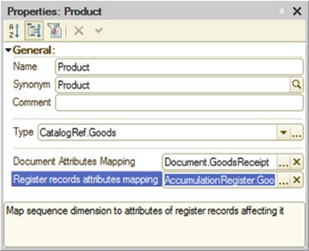
Fig. 147. Choosing attributes for column
Note. IMPORTANT. You cannot select several attributes of the same document.
If the attribute of some document is not chosen, the document journal column will not display information on all documents of this type. When choosing, use your best judgement and do not mix completely different concepts in the same column (for example, a counterparty name and the document amount).
Apart from mandatory columns (Date, Number, Document type) and columns specified in their Columns subordinate journal object the group, you can add any number of additional columns in the journal.
In case all documents with the string-type number included into the journal have the fixed number length, the Number journal column will also have a fixed length. If at least one document with the string-type number included into the journal have the variable number length, the Number journal column is created with the variable length.
Accessibility of document journal data is determined by access rights of the current user to documents and their attributes displayed in the journal. There are two accessibility groups: accessibility of journal records (in other words, document visibility in the journal) and accessibility of a journal column (content visibility of a specific document attribute). Let us review these accessibility groups in more detail:
- Accessibility of journal records. For query language access (Query object, dynamic list, data composition system), the Read right to the document journal is analyzed in the first place. If there is no such right, journal data cannot be read by a query, and therefore cannot be shown in a report or dynamic list. If the user has access to the journal, the Read right to documents registered in the journal is analyzed next. A journal record is available if the user has the Read access right to the journal and the document displayed in this record. Therefore, the document is available in the query if the user has the Read right both for the journal table and document table. If the ALLOWED keyword is specified in the query, the query result will contain only the documents for which the user has the Read right. If the ALLOWED keyword is not used in the query, an exception is thrown when trying to get data of unavailable documents.
If journal data is obtained using the data composition system with enabled control of interactive rights (dynamic list, reports), the View right of the document displayed in the record is analyzed additionally to the Read right of the document. If the View right is missing for a particular document type from the journal, data of such documents is not shown in a dynamic list or report.
- Information accessibility in the journal column and journal column accessibility. Column content in a specific row is defined by the View right to the document attribute displayed in the column and the View right to the document itself. If the user has these rights for both of them, the column displays a specific value. Otherwise, the column row contains the NULL value.
The entire column is available if the current user can see the attribute of at least one document in this column. In other words, the result of attribute availability (rules are described above) is combined "by OR" for all documents displayed in the column.
The following properties of attributes included into the column are automatically applied to the element of the form displaying the journal column:
-
Password mode. If search mode is set for at least one attribute included into the column.
-
Format. In case of the full match of attributes included into the column in all languages specified in configuration.
-
Hint. If hints match for all attributes, one hint is displayed. If hints do not match, they are displayed separated with commas.
-
Mark negatives. If this property is set for all attributes included into the column.
-
Multiline mode. If this property is set for all attributes included into the column.
-
Quick choice. The data composition system applies it to object table references of external data sources, for example, upon configuring filters.
5.10.4. Creating new documents interactively
If the document journal includes more than one document type, the journal list form offers two options for creating the new document:
- The Create button is located on the command bar and after clicking it (or clicking Ins button) the dialog box with the list of document types displayed in journal is opened.
This option is only used automatically when theCompatibility mode configuration property (see Specifying compatibility properties) is set to Version 8.3.3 and earlier.
- The common bar includes the Create button with a menu containing the list of all document types displayed in the journal. The same menu is generated after clicking Ins. The menu is generated for the current table cell. In case the journal only displays one document type, the menu is not generated.
Document types disabled by the functional options (see Functional options and functional option parameters) and for which the current user does not have the InteractiveInsert right (see Access rights description) are not automatically included in the generated menu when creating a new document.
This option is only used automatically when the Compatibility mode configuration property (see Specifying compatibility properties) is set to Version 8.3.4 or later, or Not used. This behavior is similar to command bar of the dynamic list with automated filling.
In case of automated document type list generation, the types are sorted by incoming document presentation.
If the command bar of the dynamic list or a form (when the main form attribute is a dynamic list) does not use automated filling, you can generate such menu manually. To do this, follow these steps:
-
Create the button group with the required name (for example, Create) and Submenu type in the command bar.
-
Add the Create by parameter standard dynamic list command into the group. For the button associated with this command, specify Parameter property value, document type, which will be created after clicking this button. The presentation of relevant document type (specified in Parameter value) will be used as the button presentation.
-
Add the same number of commands as the planned number of documents created with this menu.
If you create the button with the menu manually, you need to consider one moment. If you click Ins in the dynamic list, the menu will include all document types displayed by the dynamic list, not only the ones located in the command bar menu.
If the BeforeAddRow table event is processed in the journal form list, you can analyze, which document needs to be created, in this event. The parameter of Parameter event handler procedure will contain the type of created document if the document creation is initiated using the button associated with the Create by parameter command (if this parameter is specified). In all other cases this parameter value will be set to Undefined.
5.11. Enumerations
Enumeration is the service data type, which is not used separately but with other data types. The enumeration can be defined as the list of possible attribute values.
Enumerations are used when entering attribute values of documents and catalogs or when entering constant values in cases where you need to exclude ambiguous information input.
Let us use the "customer status" concept as an example. In the simplest form, there are retail customers and wholesale customers. The customer status is usually associated with the level of discount from retail price.
Such "statuses" list like retail, wholesale is an example of a simple enumeration. When writing out an invoice, the user has to specify the customer status by choosing it from the list. The specified customer status defines the prices.
If the customer status is entered during configuration of enumeration task, an expert configuring 1C:Enterprise can set the options for retail price calculation depending on the specified status.
First of all, you cannot add new items to an enumeration when performing operations with it. You can specify its values only when you configure the enumeration in Designer.
The enumeration lacks nesting. All its values are on the same level.
The main feature of enumeration is that the list of values is known and is available in Designer. The configuration uses the specific enumeration values.
Enumeration allows you to limit the number of possible options, for example, when entering a new document attribute. The list of enumeration values is created in configuration, meaning that you can organize verification of the chosen value and describe actions, which has to follow.
The Enumerations branch of configuration tree is designed to operate enumerations.
To edit an enumeration, create a list of enumeration values. The Enumeration object editing window is used to edit enumerations. When creating the new enumeration, the Use standard commands property is disabled.
On the Data tab, you can generate enumeration values.
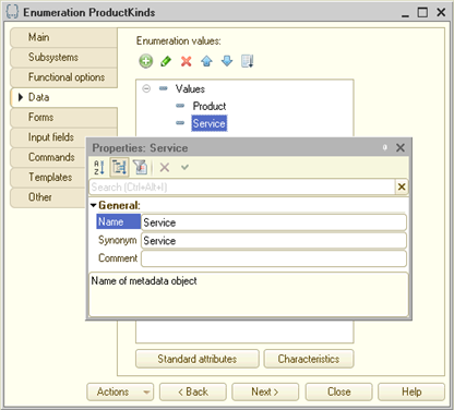
Fig. 148. Adding an enumeration value
The name and synonym are specified in the property palette.
In 1C:Enterprise mode, each enumeration value in the value list is represented by a synonym. If the synonym is not specified, 1C:Enterprise uses its name.
In the example in fig. 148, the ProductTypes enumeration value will be represented as Goods (by the entered synonym).
On the Forms tab, you can create list and choice forms. This allows you to create various forms for selection (depending on the applied context). The list forms allowed to print enumeration lists. When creating the list form, the Use standard commands property is enabled automatically.
On the Templates tab, you can create printing templates.
5.12. Reports and data processors
5.12.1. General information
Any accounting automation system only operates properly when it has the means for data processor the collected information and getting consolidated data in a format that is easy to use and analyze. As a rule, the accounting automation system allows to generate reports to do this. Designer allows you to generate sets of various reports that meet the users need for reliable and detailed output data.
The configuration objects from Reports configuration tree are used to generate reports in 1C:Enterprise. Each object of this type can contain the algorithm for generation of paper or digital report in 1C:Enterprise language or data composition scheme, which can be used by 1C:Enterprise as a basis for automated report generation (see Data composition schema). The report can contain one or various forms, which can be used to organize input of some parameters that affect the algorithm. To output the results of the algorithm on the screen or printer, the report can have the templates for describing print forms (templates) create in the wizard.
Editing the properties of Report type and Data processor type objects and creation of the subordinate objects is performed in the editing window (see Object editing window).
In 1C:Enterprise, configuration objects are used to perform various actions with the information. These objects are located inData processors branch of the configuration tree. For example, they can be used to delete outdated data from the system, import information from other systems, and many other things. The nature of performed actions reflects the name of configuration object, Data processor, because this results in changes of information stored in the system.
The processing can contain one or various forms, which can be used to organize input of some parameters that affect the algorithm. The display and printing of algorithm results are made using the print form description template wizard (templates).
The main difference between the report and data processor is the ability to use data compositions scheme (for details, see Data composition system). In other details the data processor is the same as the report.
You can use the same report forms, settings, and report options for several (or all) report forms of the application. To do this, use common forms. In general, there are several use options:
-
The same set of forms is used for all reports of the application. In this case, create the required forms and specify them in the configuration properties (see Specifying presentation properties). In this case there is no need to develop forms in reports because the common forms will be used.
-
You can specify sets of reports, for which the custom forms are acquired. In this case the common forms for operating reports are created, which are specified for each report in "their" group. This way you can create, for example, a special set of forms for accounting reports or for analytics reports.
Note. Note. In case the same common form is set as the main form of several reports, you will only be able to open one such report in thick client (in regular mode).
If the Open new window standard command is used in the report form, remember, that the parameters transferred to the form, from which the standard command was used, are not transferred to the new window.
5.12.2. External data processors and reports
5.12.2.1. General information
External data processor in 1C:Enterprise is the data processor stored outside of configuration in a separate external data processor file. External data processor performs the same tasks as the Report-type or Data processor-type configuration objects.
The external report in 1C:Enterprise is the report stored outside of configuration in a separate external report file. The external report performs the same tasks as the Report-type configuration object.
The main task of the external data processor (report) is to implement, provide, and update features without affecting the configuration.
External data processors and reports can be stored in two formats:
-
Binary files with .epf and .erf extensions. These files can be used for editing in the Designer. They can also be used in 1C:Enterprise mode. You can develop and debug while operating the 1C:Enterprise. In this case, development and debugging of the data processor (report) take significantly less time. The external data processor (report) is edited and saved in Designer mode without saving the whole configuration, but started in 1C:Enterprise mode. To execute the external data processor (report), you have to upload it with File – Open. It operates similar to any other application (report).
-
XML file with extension that corresponds to files used in configuration export/import into files (see Dumping configurations to files/Restoring configurations from files). When using this format, you can only edit an external data processor (report) in Designer mode. To use the external data processor report in 1C:Enterprise, save it with .erf/.epf extension. The 2.0 format is used for its operation.
Note. Note. External data processor (report) that is opened using the File –Open menu, are performed in safe mode (see Safe mode) if the user does not have administrative access rights.
Any configuration object of the Data processor-type or Report-type can be saved into the external data processor (report) file and vice versa – the existing configuration object can be replaced with the external data processor (report). A help information can be created for external data processor (report), just like for any other configuration object.
Note. Tip. To ensure configuration integrity, it is recommended that you use external data processors (reports) for debugging. After debugging of the data processor (report) generation algorithm is over, include the external data processor into the configuration.
Saving the external data processor (report) into XML is required when you plan to store the data processor (report) into the external version control system. In this case, the XML format is more convenient than .epf (.erf) extension. Designer allows opening external data processor (reports) for editing in any format. In this case, by default the writing is performed in the format of data processor (reports) opened in the Designer. To change the storage format, execute the File – Save as… command or File – Save copy… and choose the required saving format in the opened dialog box.
5.12.2.2. Creating external data processor (report)
To create the external data processor (report), choose File – New and then, in the displayed request, choose External data processor or External report.
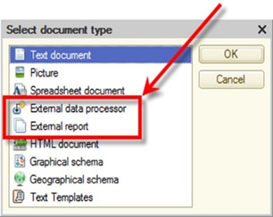
Fig. 149. Document type selection
The form editor for external data processor (report) development will be displayed. The editing window of external report will additionally include controls for creation, setting, and editing the data composition system.
An external data processor (report) is not a part of the current configuration (although it is very closely connected with it) and its saving procedure is different from the procedure for saving configuration changes (see Saving configurations). To save the external data processor (report), click File – Save, File – Save as…, or File – Save copy. In the standard file saving dialog box, choose the required saving option (see General information) and then choose a name of the saved external data processor (report).
5.12.2.3. Using external data processors (reports)
To use the external data processor (report) when operating 1C:Enterprise, it has to be opened the same way as in the Designer. However, remember that in 1C:Enterprise, the external data processor can only be opened for execution, the user cannot edit it. The attempt to open is followed by the verification of access rights. Then, the safe mode is enabled if the user does not have the administrative rights. To execute the external data processor (report), save it in binary format (.epf, .erf). For more information, see General information.
The compilation of an external data processor (report) module is performed when opening the external data processor (report). That is why, when editing the external data processor (report) in Designer and saving it, you need to open this data processor in 1C:Enterprise mode once again.
The external data processors (reports) can also be operated on the 1C:Enterprise server. All limits for interactive objects (forms and so on) usage are the same.
To operate the external data processor (report) from 1C:Enterprise language, you must connect it using theConnect() method (only available on the 1C:Enterprise server).
// Place the data
processor into temporary storage on the client
StorageAddress = "";
Result = PutFile(StorageAddress, "ExtDataProcessing.epf", , False);
... // On the server, connect the data processor from previously created
// temporary storage.
DataProcessorName = ExternalDataProcessors.Connect(TemporaryStorageAddress);The name of external data processor will be placed to the DataProcessorName variable. This name will be used to call the connected data processor. Example, when opening the data processor form:
// Let us open the form
of the connected external data processor
OpenForm("ExternalDataProcessor."+ DataProcessorName +".Form");You can attach an external data processor or report in safe mode (see Safe mode). To do this, use SafeMode parameter of the Connect() and Create() connection methods. The external data processor (report) connection mode will depend on the value of this parameter:
-
If the parameter is set to True, the external data processor (report) will be attached in safe mode.
-
If the parameter is set to False, the external data processor (report) will be attached in unsafe mode.
-
The security profile name is set as the parameter value:
-
If no name is specified, the external data processor (report) will be attached in safe mode.
-
If the profile name is specified and the Safe mode security profile parameter is set to True for this profile, the external data processor (report) will be attached and controlled by the security profile with the specified name.
-
If the profile name is specified and the Safe mode security profile parameter is set to False for this profile, the external data processor (report) will be attached, but controlled by the default security profile.
-
If there is no security profile with the specified name on the 1C:Enterprise server, the external data processor (report) will be attached in safe mode.
-
The external data processor (report) might contain malicious code. For more information, see Unsafe action protection. That is why, in case of an attempt to open the external data processor (report) interactively, they permission request will be displayed to the user.
If you answer Yes in this dialog box, this choice will be remembered and further openings of this data processor (report) will not display any questions. If you answer No, the data processor (report) will not be opened. This question will be displayed again with the next opening.
You can attach an external data processor or report so that the interface language of the object to be attached differs from the current system interface language. To specify this language, use the LanguageCode parameter of the Connect() method. If a language code is not specified, the current interface language will be used. To get this language, use the CurrentLanguage() global context method.
For programmatical operation the external data processor (report) can be located:
-
In a file located in configuration (for example, in a template).
-
In infobase data.
-
In the temporary storage (see Temporary storage).
The names of external data processors (reports) must be unique within the session. In case of problematical or interactive connection of the external data processor (report) with the same name as the external data processor (report) that was already loaded during this session, the old data processor will be disconnected and the new one will be connected.
Note. Note. When operating the external data processors (reports) in thick client, remember that you can only open managed forms when operating in the managed application mode, and only regular forms in the normal mode.
When operating the external data processors (reports), remember:
-
If you connect the new data processor (report) with the same name as the already connected data processor (report), the opened form from the old data processor (report) are disabled (the error is displayed).
-
When connecting the external data processor (report), in case the external data processor (report) is binary identical to the already connected one and the safe mode flag is the same, there is no actual reconnection and the error is not displayed. Otherwise, the previously connected external data processor (report) is disabled and the new one is connected.
-
When executing theCreate() method, the SafeMode method parameter is ignored, if the external data processor (report) was previously connected with the Connect() method. If the connection is the first one, the external data processor (report) will be connected using the SafeMode parameter from the Create() method.
-
When the external data processor (report) is connected programmatically with the Connect() method you can specify, whether the control of unsafe operation is required. For this use the UnsafeActionProtection method parameter.
-
When getting a form for an external data processor (report), an opened form will be found. It does not matter whether it was opened for the currently connected data processor or for the previously connected one (with the same name).
-
If you click Service and settings – File – Open, the OpenForm() method with the Uniqueness parameter set to True opens the data processor (report) form. This way you can open a new data processor form in case of changes.
-
If not specified explicitly, all of the above features are equally applied to both interactively and programmatically opened external data processor (report).
5.12.2.4. Editing external data processors (reports)
The external data processor (report) is edited in the Designer. To open the existing external data processor (report), choose File – Open. In the displayed standard dialog box, choose the file type corresponding to the format of the saved external data processor (report) and specify the name of the file opened.
When opening the external data processor (report) in the Designer the object editing window is opened automatically. Unlike other configuration objects, the debugging of external data processor (report) can be performed without restarting the 1C:Enterprise. You only need to call the data processor report again in 1C:Enterprise mode after saving it by the Designer (only for the data processor (report) saved in .epf/.erf).
You can copy the external data processor (report) in the editing dialog box without changing the object edited. To do this, click Actions – Export to files. Apart from copying the external data processor (report), you can choose the export format (see General information). By default, during this operation, 1C:Enterprise offers the export format that is different from the current format. It means that if the edited external data processor (report) has the .epf/.erf extension, the XML format will be offered and vice versa. You can replace the edited external data processor (report) with another external data processor (report), which is located in the file (in any of the supported formats).
When exporting/importing the external data processor (report) to/from the file, you can change the object type without changing the object edited. For example, you can export the edited external data processor as the external report and vice versa, and the object edited will keep the type.
5.12.2.5. Help information
The external data processor (report) can be complemented with the user description. To edit the description, click Open link of the Help information property in the external data processor property palette.
To view the description of external data processor (report) in 1C:Enterprise mode, click F1.
5.12.2.6. External data processors (reports) and configuration objects
5.12.2.6.1. General information
The Report-type and Data processor-type object in the configuration can be modified into external reports and data processors and vice versa: external reports and data processors can replace the existing configuration object of Report-type or Data processor-type. External reports and data processors can also be added into configuration structure as new configuration objects of Report-type and Data processor-type.
When operating the external data processor (report) you can choose the format of the object saved. It can be done in the saving dialog box or by opening the file with the drop-down File type list. In defines, whether the data processor (report) will be saved as .epf/.erf,or in XML format (see General information). In this section, the choice of external data processor (report) format will not be described in detail.
5.12.2.6.2. Copying data processors (reports) into external data processors (reports)
The existing configuration object of the Report-type or Data processor-type can be copied into an external data processor or a report. To do this, select the configuration object in Configuration window and choose Save as external data processor/report in the context menu of the configuration object.
This will result in creating an external data processor report, which will be a copy of the selected configuration object. The configuration object itself will not change.
This operation only makes sense for further debugging the data processor (report) created. After the debugging, the external data processor (report) can be entered in a configuration instead of the existing configuration object. Remember that to execute the data processor in 1C:Enterprise mode, you must save it as .epf/.erf and not in the XML format.
5.12.2.6.3. Replacing data processors (reports) with external data processors (reports)
External data processors (reports) can replace the configuration objects of Report-type and Data processor-type. To replace the configuration object with the external data processor (report), select its name in the Configuration window and use Replace with the external data processor/report item in the context menu of the configuration object.
5.12.2.6.4. Adding external data processors (reports) to the configuration structure
The existing external data processor (report) can be added into the configuration structure as the new Data processor-type or Report-type configuration object. The do this select any name of Data processor-type or Report-type configuration object into consideration structure and use the Insert external data processor, report context menu item of the configuration object. As a result, the new data processor (report) will appear in the configuration tree.
5.12.2.7. Comparing and merging external data processors (reports)
External data processors (reports) can be compared and merged with data processors (reports) from configuration as well as other external data processor (reports).
To compare the report or data processor, open the Configuration, specify the acquired object and choose Compare, merge with data processor, report… in the object context menu. Then choose the external data processor (report) in the standard dialog box for choosing the file.
The Comparison and merging… window will be displayed. The operations in this window are the same as in case of configuration merging (see Comparing and merging configurations).
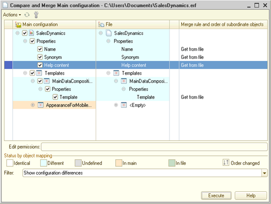
Fig. 150. Merging data processors
To compare or merge the external data processor (report) with another one, open the source external data processor (report) and click Actions in the editing window. Then choose Compare with external data processor, report in the drop-down menu. Choose the external data processor (report) in the standard file choose in dialog box. For further steps, see Comparing and merging configurations.
5.12.3. Report display management
1C:Enterprise runs on different devices. One of significant differences between devices is the size of the screen where information is displayed. At the same time, some reports can be quite wide. To make reports more convenient to use on screens of different sizes, 1C:Enterprise platform provides several different tools.
1C:Enterprise has a special functionality that converts a regular report into a compact one. This functionality converts the spreadsheet document that displays the report so that the resulting spreadsheet document has only vertical scrolling and does not require horizontal scrolling. This conversion is performed by rearranging report items. As a result of this conversion, the report will fit any device, and the developer will not need to develop a separate report version (or versions) for devices with small screen sizes. The conversion functionality can be used in two ways:
-
Automatically, by specifying several report form settings
-
Using 1C:Enterprise language methods
In the vast majority of cases, automatic result conversion is quite sufficient. For automatic report conversion to work, three extension properties of the client application form must be specified for the report form:
-
Report result. In this property, the developer must specify the form attribute where the report generation result will be placed.
-
Report result display mode. This property specifies the report mode to be used by default. This property can have the following values:
-
Regular. In this case, the report will be displayed as it was generated.
-
Compact. In this case, the original report will be converted to compact display mode.
-
Auto. This value is interpreted as follows:
-
For mobile devices: Compact.
-
For personal computers: Regular.
-
-
-
Apply display mode when the report result is set. This property specifies system behavior when a new value is placed from 1C:Enterprise language in the form attribute specified in the Report result property. This property can have the following values:
-
Apply. The result display mode will be automatically applied to the spreadsheet document assigned to the attribute specified in the Report result form property.
-
Do not apply. When you change the attribute specified in the Report result form property, no actions are performed.
-
Auto is interpreted as Apply.
-
When the screen is rotated (for mobile devices), the form attribute value specified in the Report result form property is checked. If an ordinary spreadsheet document is placed in the attribute, the report is not converted to a compact one when the screen is rotated.
When the developer needs to explicitly specify which report display mode is required at a particular time, they can use the SetResultViewMode() method of the client application form extension for the report form. When the display mode is changed, the report result is converted according to the new value. In this case, the value of the Apply display mode when the report result is set property is not analyzed. When you call this method on the client, a server call might be required when the result display mode changes. The user can change the result display mode interactively. To do it, click More actions – Compact mode.
To get the current result display mode, you can use the GetResultViewMode() or GetCurrentResultViewMode() methods. Both methods return the current value of the display mode set in Designer considering the values stored in the system settings storage. If the result display mode has been changed from the application code (or user interface), both methods will return the set value. However, if the current display mode value is Auto, the GetCurrentResultViewMode() method converts this value to a specific display mode depending on the current client application. The GetResultViewMode() method will not perform such conversion. In fact, behavior in relation to the Auto value distinguishes the GetResultViewMode() and GetCurrentResultViewMode() methods: the former does not change it in any way, while the latter converts it to the actual result display mode.
Now we can look at the example that shows the interaction between the Report result display mode and Apply display mode when the report result is set properties when the developer generates a report and configures its display settings in the form:
- Form properties are set to the following values:
-
Report result display mode is set to Regular.
-
Apply display mode when the report result is set is set to Apply.
-
The spreadsheet document that contains the report is assigned to the Report result form attribute.
-
In this case, the system applies the regular display mode to the report as set by the form properties.
-
Then the application code calls the SetResultViewMode() method that sets the compact result display mode.
-
The system automatically changes the displayed report appearance.
-
A new report is generated and a new spreadsheet document is assigned to the Report result form attribute.
-
The system will transform the report to a compact mode because at the step 4 we set the compact report result mode.
Therefore, the described properties allow you to "pass" the control over report display to 1C:Enterprise platform. The developer only needs to set required values or use default values.
To convert a spreadsheet document to one or another display mode, use one of the following methods of the SpreadsheetDocument object: ConvertToCompactDocument()/RevertToDefaultDocument(), GetCompactDocument(), or SetHorizontalStretch(). The ConvertToCompactDocument() method converts a spreadsheet document to a new display mode. As the first parameter of this method, specify the width of the area where the new spreadsheet document will be displayed. This value is specified in abstract numbers that describe the average width of a spreadsheet document character. To adapt a document to the current screen with maximum accuracy, you can get the first parameter value by calling the GetRecommendedReductionWidth() method of the form field extension for the spreadsheet document field.
Once the ConvertToCompactDocument() method is completed, two documents are generated for the spreadsheet document: regular and compact ones. If you call the RevertToDefaultDocument() method, the compact document will be lost. You can cancel conversion only if the spreadsheet document has been previously converted to compact mode.
The GetCompactDocument() method works similarly to the ConvertToCompactDocument() method, but the conversion result is returned as a new spreadsheet document.
To set the HorizontalStretch property for all spreadsheet document columns, use the SetHorizontalStretch() spreadsheet document method. The parameter value of the SetHorizontalStretch() method serves as the value of this property.
5.13. Charts of characteristic types
5.13.1. General description
When developing applications, you often need to store properties of the applied objects with the unknown content and type (on the application development stage).
Examples of such properties:
-
For products or services, it can be color, size, dimensions, and so on.
-
For the contractor, you can specify the federal district where their contractor is located, or the regular customer flag, and so on.
-
For a chart of accounts, you can specify the quantity and type of profiles for analytical accounting (for the specific account). Then the specific analytical accounting profile values are specified for each posting. For more information on organizing analytical accounting, see Analytical accounting.
When developing, the content and type of data stored is not specified for such properties (hereinafter characteristics). It is also possible that the list of such characteristics will be quite large and each application user will have to operate it. Please note that the characteristics can be different for various objects groups. For example, for one product group, you can specify color and size. While for other, only dimensions are used. Note that users can enter characteristics themselves during the operation.
There are two ways to do this:
-
A separate attribute of the required type is created for each characteristic in the relevant object. This way has several disadvantages:
-
Each characteristic is a separate field in the database table, which will take up space in the database no matter whether the characteristic is used.
-
When there are a lot of characteristics, there will be a lot of "redundant" fields. It will not be convenient for both the developer and the user to operate with them.
-
If you need to add a new characteristic, you will have to customize the application: add a new attribute and consider it everywhere in the application. This requires a lot of effort and is inconvenient.
-
-
Using the special objects, which describe characteristic name, type and so on. This model does not have the disadvantages of the previous one. To add a new characteristic, you do not have to change the application. It also does not require extra space in the database. The user can also add the new object characteristics. The 1C:Enterprise provides such object. It is called a chart of characteristic types.
However, there are some disadvantages. The characteristic organization and usage logic is more complex. You will have to spend more because of the more complex way only once, when developing the application. While the number of characteristics and types increases, the additional customization of an application is not required.
The chart of characteristic types can be used to organize the analytical accountant. In this case each element (with the unique set of types) will be the extra dimension type and when editing the account in the chart of accounts you can specify the extra Dimension types used for the specific account. When generation the posting, the extra dimension components (of the relevant type) will be used for filling, irregardless of the extra dimension type set when editing the chart of accounts. For more information on how to use the chart of characteristic types for analytical accounting, see Analytical accounting.
5.13.2. Configuration object characteristics
5.13.2.1. General information
The chart of characteristic types is a central element of characteristics feature:
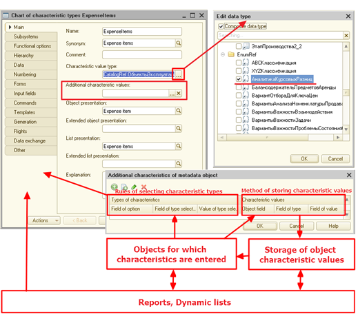
Fig. 151. General scheme of characteristics operation
The chart of characteristic types (see fig. 151) stores a set of types that can be specified for the items of the chart of characteristic types (characteristic types) in the Characteristic value type field. The chart of characteristic types also includes information on the opportunity to create characteristics, in case the infobase lacks the objects required to describe values of such characteristics. The Additional characteristic values field and specifying the required type in Characteristic value type list is used to do this.
When creating a characteristic type (the chart of characteristic types element) you can specify, which set of types will be the limit for values of this characteristic type. The set of types specified for the chart of characteristic types can be limited for a specific characteristic type but it cannot be extended.
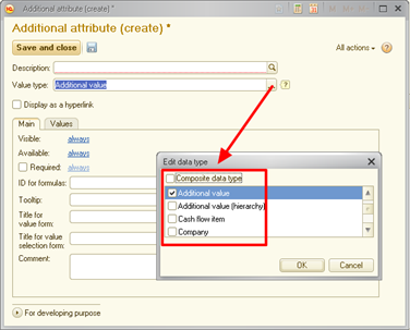
Fig. 152. Setting the characteristic type
For those metadata objects, for which you plan to implements that characteristic accounting, use Additional metadata object characteristics dialog box (see fig. 152) to specify is rules for filtering the characteristic types and rules for getting characteristic values what specific data objects. In fact, the following rules as specified:
-
How to get characteristic types for a specific data object: filtering rules. 1C:Enterprise uses specified rules to create a request for getting the list of characteristic types. This request is generated using the ALLOWED keyboard. As a result, only those characteristic types will get to the list, for which the user has the right. The rights of a specified by the data access restriction set for the table with the characteristics list (see Data access restriction).
-
How to get a characteristic value, knowing the data object and a characteristic type: rules for getting a value. 1C:Enterprise uses specified rules to create a request for getting the list of characteristic values. This request is not independent. It creates that table, which connects to the main request that gets the application data. That is why, using or not using the ALLOWED keyword is defined by the main request.
Object attribute properties used in the characteristic feature require to specify some metadata properties that 1C:Enterprise needs to automatically prepare data for the user.
After all settings are ready and the characteristic types list is generated (as a predefined chart of characteristic types elements in the Designer mode or as values entered in 1C:Enterprise mode), you can edit the characteristic values for the specific data object.
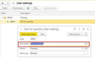
Fig. 153. Editing the characteristic value
If the form has the fields for the data object, characteristic type, and characteristic value the editing process is as follows:
-
The user chooses the data object (Object field, fig. 153), for which the list of characteristics needs editing. For example, a catalog item.
-
1C:Enterprise generates a list of characteristic types available for this object. When generating the list, characteristic type filtering rules specified for the metadata object are applied.
-
1C:Enterprise uses information from the chart of characteristic types to define types of the editable value and sets up form items (choice parameter links, type link, and so on).
-
Now the user can choose the required characteristic types (Characteristic type field, fig. 153) and set the characteristic values (Characteristic value field, fig. 153).
When using characteristics in reports (see Using characteristics in reports) and dynamic lists (see Using characteristics in dynamic lists), the similar operation scheme is used.
In some cases, implementation of the characteristic feature (examples of the implementation are described below) might require a reduced set of objects. However, using the chart of characteristic types is required with any set of objects used.
5.13.2.2. Editing the chart of characteristic types
The structure of a chart of characteristic types is similar to the catalog (see Catalogs). The chart of characteristic types can be hierarchical, contain predefined items (see Predefined data). It might have attributes, tables, and so on. The main difference between the chart of characteristic types and the catalog is the Characteristic value type property. This property describes the list of types, which can be later specified as the value type (one or several) of the specific characteristic type. Types can be selected without changing the structure and the application code. Note that to set the type of attribute storing the characteristic value connected to the specific chart of characteristic types, there is a special Characteristic.<ChartOfCharacteristicTypesName>. The attribute, for which the type is specified, cannot be union.
If the Characteristic value type property includes Day, Date, CatalogRef.Products and CatalogRef.Contractors types, you can create Size characteristic type with Number type or Supplier characteristic type with CatalogRef.Contractors type. However, you cannot create a characteristic type with the Boolean type as such type is not included into the Characteristic value type property. Thus, choose the types set carefully when creating the chart of characteristic types.
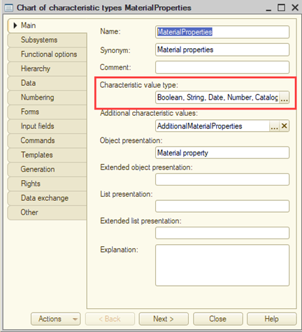
Fig. 154. Characteristic value type property
When choosing the Number, Row or Date primitive types in Characteristic value type property, specify type dimension or content that cover all possible values in the data type editing dialog box. So, if you do not specify the decimal part of a numeric type, you cannot enter a fractional number.
Note. Important. Changing the list of type, characteristic types used, after entering custom values can lead to loss of user-entered values. For example, if you delete some type from the type list, the characteristic values associated with the delete the type will be cleared, too. In case the deleted type was the only one, the new type of this characteristic type will be all types specified in Characteristic value type property.
Creating a chart of characteristic types is not the only step to implement the characteristic accounting feature for metadata objects. Depending on the task, and you have to create additional metadata objects and configure them in a special way. The examples of the characteristic feature implementation are described below.
5.13.2.3. Examples of the characteristic feature implementation
-
The simplest example of the characteristic accounting feature. The separate chart of characteristic types is created for each metadata object. This chart of characteristic types stores characteristic values. For more information, see Example 1.
-
In of the examples, the developer needs to create characteristic types, which are not described in the application. That features from the previous example are the same. For more information, see Example 2.
-
Use this example when you need to utilize one chart of characteristic types to describe characteristic types of all metadata objects and one information register to store characteristic values. For more information, see Example 3.
-
Use the example when you need to utilize the same characteristic type for different metadata objects (characteristic sets). The characteristic values are stored in an information register. For more information, see Example 4.
If you need to limit access to characteristics and their values using the access restriction feature of data applied to the object itself, you can use this implementation example.
Note. Note 1. The examples given in this section are not complete. They are intended to demonstrate various techniques of handling characteristics.
Note. Note 2. The example of characteristic accounting above is not complete. It is intended to demonstrate the basic examples of such accountant.
5.13.2.3.1. Example 1
Task
Characteristic types are stored in chart of characteristic types, and each chart of characteristic types "serves" one metadata object. It means that the ProductsCharacteristics chart of characteristic types is created for the Products catalog, the CounterpartyCharacteristics chart of characteristic types is created for the Counterparties catalog, and so on. Characteristic values for specific objects will be stored in information registers. Each information register will store information on data, characteristics types and characteristic values of one "metadata object – chart of characteristic types" pair. To simplify, we will review one metadata object, one chart of characteristic types, and one information register.
Implementation
Create two dimensions and one resource in the information register designed to store characteristic values. Dimensions will be responsible for the object, for which the characteristic value and type are store, and the resource will store the characteristic value itself.
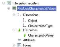
Fig. 155. ProductsCharacteristicValues information register
Let us have a closer look at the register (ProductsCharacteristicValues):
- Object is a dimension. It contains a link to data object, for which is a characteristic value is stored. A dimension will have the type of metadata object, for which the characteristics will be stored. In the current example this value is CatalogRef.Products.
The Master property must be set for the dimension. This will allow you to automatically delete object characteristic value when object is deleted and to open the list of characteristics directly from the objects form (the link is located in navigation panel form).
-
CharacteristicType is a dimension. Contains a link to characteristic type (specify ChartOfCharacteristicTypesRef.ProductsCharacteristics as the value type). Values from chart of characteristic types will be added to this dimension.
-
CharacteristicValue is a resource. It stores a value of one of the types of chosen as value type of characteristic type specified in the CharacteristicType dimension. The resource value type will be Characteristic.ProductsCharacteristics. For this resource, you cannot specify a union type that consists of several Characteristic types. That is why, to store characteristic values (in this particular example), you need to use several information registers: one for each "metadata object – chart of characteristic types" pair.
Add the Filter.Owner parameter connected to the CharacteristicType dimension and the Clear usage mode to the Choice parameter links property (see Choice parameter links) for the resource. This setting during the editing in the form will clear characteristic value when changing characteristic type.
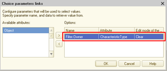
Fig. 156. Value resource settings
You also have to fill the Type link resource property. The CharacteristicType dimension must be specified in this property. Once the connection is specified, one feature of the Chart of characteristic types object will be enabled. Depending on the characteristic type specified in the CharacteristicType dimension, the system will automatically change the list of available types for the CharacteristicValue resource.
The next step is to describe the connection between an object, for which the characteristics are accounted, the chart of characteristic types, and information register to the 1C:Enterprise. This must be done using the Additional characteristics of metadata object window. It can be called from the metadata object context menu (Characteristics item).
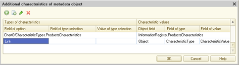
Fig. 157. Characteristics of the Products catalog
In this window you describe, which object provides characteristic types and how it does it (left part of the window) and where are the characteristic values stored (right part of the window). In the current example:
-
Characteristic types are located in ProductsCharacteristics chart of characteristic types (Characteristic types field).
-
Characteristic type and its presentation will be retrieved from the chart of characteristic types item. The Link standard attribute will be used as a key field (the Key field property) for searching for the required chart of characteristic types item.
Storage description will be used by 1C:Enterprise when it needs the list of characteristic values for some metadata objects.
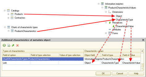
Fig. 158. Characteristic values
For example, to get the list a filter values in dynamic list. In this example the following scheme for characteristic value storage is described:
-
The ProductsCharacteristics information register is used for storage (Characteristic values property).
-
To store the object, for which the characteristic values are specified, the Object dimension is used (CatalogRef.Products type). This is set in Object field property.
-
To store the link to object characteristic, the CharacteristicType dimension is used (Field of type selection property).
-
Characteristic value is stored in CharacteristicValue resource (Value field property).
In general, any object with the attributes of the required type can be used as an object for characteristic value storage:
-
The attribute of the same type as the object, for which the characteristic value is stored, is an object field.
-
The attribute of the same type as the chart of characteristic types, which stores the characteristic, is a field of type selection.
-
The attribute of the same type as the characteristic value (the characteristic value) is a value field.
When you edit the fields of Characteristic values dialog box, 1C:enterprise will give you a choice from objects that meet requirements stated above (the Characteristic types field must be filled in the string, where the editing is made). Editing the characteristics is available for the following metadata objects:
-
Catalogs
-
Documents
-
Enumerations
-
Charts of characteristic types
-
Charts of accounts
-
Charts of calculation types
-
Exchange plans
-
Business processes
-
Tasks
Result
Implementation of this example will allow you to:-
Create characteristic types required for the element of "their" metadata objects in the chart of characteristic types.
-
Specify the separate set of characteristic for each Products item in the catalog and specify the required characteristic value for each characteristic type.
5.13.2.3.2. Example 2
Task
Let us look at the situation where the user has to add a characteristic if the application does not have a type for this characteristic. For example, you need to consider color for the products item, but there is no catalog in the application.To complete such task, you have to create a special catalog, which will be the additional characteristic values storage. This catalog will be subordinate to the chart of characteristic types. Then you need to specify this catalog in a special property of the chart of characteristic types: Additional characteristic values. This catalog must also be specified as one of the possible Characteristic value type property type.
Implementation
Let us create a catalog that will store additional characteristic values (it will be called CharacteristicValues). All other application objects will be similar to example 1 (see Example 1). Then, perform the following actions with the catalog:- Specify the CharacteristicValues chart of characteristic types as the catalog owner. As a result, the only values set available for the characteristic type is the one specified for the particular characteristic type.
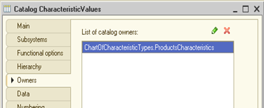
Fig. 159. CharacteristicValues catalog owner
-
Specify the CharacteristicValues catalog is one of the compound values of the Characteristic value type property of the ProductsCharacteristics chart of characteristic types.
-
Choose the CharacteristicValues as a values of Additional characteristic values chart of characteristic types property.
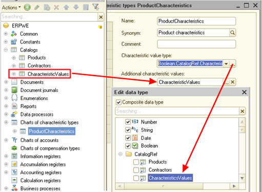
Fig. 160. Additional characteristic values property
The settings in the Additional characteristics of metadata object window for Products catalog are the same.
Result
Implementation of this example will allow you to:-
Create characteristic types if the application does not have types for storing its values (additional characteristic values).
-
Specify additional characteristic values as characteristic values.
5.13.2.3.3. Example 3
Task
This example is applicable when you need to use one chart of characteristic types to describe characteristic types of all metadata objects and one information register to store all characteristic values. Distribution of characteristic types between metadata objects will be performed using the chart of characteristic types attribute. The value of this attribute will define an attachment to the specific object (attribute contains value) or all metadata objects (attribute is not set).Implementation
You need to create a chart of characteristic types (named ObjectCharacteristics). Create TypeOfCharacteristicType attribute for the object created and set Enumeration.ObjectTypes as an attribute type. The content of enumeration will define the metadata objects, for which characteristic types will be stored.Note. Note. To increase the speed of filtering by a required characteristics type, it is recommended that you set the Index property of the TypeOfCharacteristicType attribute to Index with additional order.
To store attribute values, create an information register called ObjectCharacteristicValues. Take its content and settings from Example 1 (the ProductsCharacteristicValues register, see Example 1). The difference from Example 1 is that the type of Object dimension will be compound and the types must include all reference types, for which the characteristic accounting is planned.
Similar to Example 2, create a catalog for additional characteristic values accounting (see Example 2).
In the result, the following metadata object structure must be created:
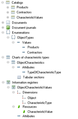
Fig. 161. Configuration structure
In this example, it is supposed that characteristics will only be considered for the Products and Counterparties catalogs.
Now we have to "explain" the way to filter characteristic types for this or that data object to 1C:Enterprise (it must be done for each object with characteristics):
-
In which object is the characteristic list located.
-
What key field will be used to get the specific characteristic to identify the value type (characteristic type) and characteristic presentation.
-
Which characteristic attribute (and filter value) will be used to define the list of characteristics associated with a specific metadata the object.
Below is an example of characteristic filter rule specification for Products catalog.
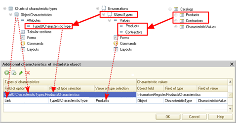
Fig. 162. Docking characteristics to metadata objects
The setting in the Additional metadata object characteristics window is the same as in Example 1 (see Example 1). Additionally, you must specify the values of two fields:
-
In Types filter field property specify, which chart of characteristic types attribute is the key field that will be used to filter characteristic type for this or that data object. In this example, it is the TypeOfCharacteristicType attribute of the chart of characteristic types.
-
The Types filter value property contains a value that must be included into an attribute specified in Types filter field property. This make the chart of characteristic types item (specified in Characteristic types property) "appropriate" for the required metadata object. In this example the Products catalog is configured, so for the Types filter value property the ObjectTypes.Products enumeration value is set.
If the application includes characteristic types that can be used with all objects, for which the characteristics are accounted, 1C:Enterprise can be configured in such way that the list of characteristic will include the characteristic types "attached" to the metadata object as well as common characteristic types. To enable this, add another row in the characteristic settings window:
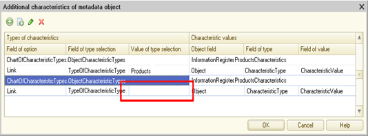
Fig. 163. Filtering "free" characteristics
In this case the "general" characteristic types on the ones, for which the TypeOfCharacteristicType attribute value is not filled. Characteristic value storage is described similar to Example 1 (see Example 1).
Extension
In the current example, if you need the characteristics support for new metadata object, do the following:-
Add the required value to the ObjectTypes enumeration.
-
Add the type that corresponds to the data object, for which the characteristics accounting is configured, to the Object dimension of the ObjectCharacteristicValues register.
-
The properties in Additional metadata object characteristics are the same as in the examples about.
Result
Implementation of this example will allow you to:-
Use the same chart of characteristic to store characteristic types of all objects.
-
Divide characteristic types into "attached" to the specific objects and common for all objects.
5.13.2.3.4. Example 4
Task
This example can be used when one characteristic type has to be used for several metadata objects. For example, the Delivery date characteristic type can be used for contractor (for example, it could mean the date of products delivery by the contractor) and for goods (in this case in will mean the date of some product delivery). To implement this Task using the previous example (see Example 3), you will have to create several characteristic types attached to specific metadata objects and with the same names (to simplify identification).The scheme that meets the above requirements looks as follows:
-
The chart of characteristic types will keep the characteristic type list.
-
Predefined data of a special object (catalog) stores characteristic sets. They consist of characteristics that can be set for metadata objects, where specification of characteristics is allowed. The list of available characteristics is set in 1C:Enterprise not the Designer.
-
The characteristic values are stored in an information register.
Implementation
Let us have a closer look at this schema. We will take the Products catalog as an example. The chart of characteristic types is the same as in the previous examples. To store the acceptable characteristics sets, create a dedicated catalog (named CharacteristicSets). In this catalog, create the SetContent table. In the table, create one CharacteristicType attribute (a link to the ChartOfCharacteristicTypesRef.ObjectCharacteristics chart of characteristic types) and as many predefined items as there are metadata objects, for which you plan to consider the characteristics. In the current case, this catalog must include one item for Products catalog.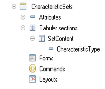
Fig. 164. Storing characteristics list in a catalog table
Information register, in which characteristic values of objects are stored, is the same as the register suggested in Example 3 (see Example 3).
The next step is establishing connection between metadata object, the object storing characteristics list, and the object storing values of the selected characteristics:
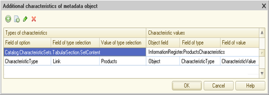
Fig. 165. Interactive setting
As a result, the following scheme is created:
-
The presentation and characteristic value types are generated using the indirect addressing. The Key field property of the characteristic setting window is used for this.
-
To get the list of available characteristics (for Products catalog), use the predefined Products item of the CharacteristicSets catalog. To enable this, the Types filtering field property specifies that the required item from the CharacteristicSets catalog will be sorted by the key Link field. The filter value (Types filter value property) is the link to predefined item.
-
Storage of characteristics values is not the same as in the above examples.
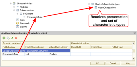
Fig. 166. Indirect addressing of chart of characteristic types
The schema for storing characteristic list does not provide automatic generation of characteristic choice list when adding a new characteristic to an object (from the list of available ones). To generate such list, generate a choice form for a metadata object from the chart of characteristic types and you must do it in a specific manner.
To do this, use the wizard to generate choice form for the metadata object from the chart of characteristic types. In the created form, select the Custom query checkbox for the main form attribute (List attribute of the DynamicList type) and set the following request as a source of the dynamic list:
SELECT
ChartOfCharacteristicTypes.Link, ChartOfCharacteristicTypes.DataVersion, ChartOfCharacteristicTypes.DeletionMark, ChartOfCharacteristicTypes.Predefined, ChartOfCharacteristicTypes.Code, ChartOfCharacteristicTypes.Description, ChartOfCharacteristicTypes.ValueType
FROM
ChartOfCharacteristicTypes.ObjectCharacteristics
AS ChartOfCharacteristicTypes
{INNER JOIN
Catalog.CharacteristicSets.SetContent AS CharacteristicSet
ON
ChartOfCharacteristicTypes.Ref = CharacteristicSet.CharacteristicType}
{WHERE
CharacteristicSet.Ref.* AS CharacteristicSet}You must also specify ChartOfCharacteristicTypes.ObjectCharacteristics as the main table of the dynamic list and select the Dynamic data reading checkbox.
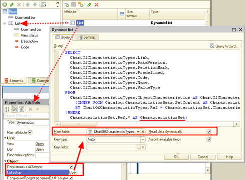
Fig. 167. Chart of characteristic types choice form
In the form module, specify the OnCreateAtServer event handler:
&AtServer
Procedure OnCreateAtServer(Cancel, StandardProcessing)
Predefined = New Map;
Predefined.Insert(Type("CatalogRef.Products"), Catalogs.CharacteristicSets.Products);
If Not
Parameters.Property("CharacteristicTypesFilterObject") Then
Return;
Else
FilterObject
= Parameters.CharacteristicTypesFilterObject;
FilterObjectType
= TypeOf(FilterObject);
If Predefined.Get(FilterObjectType) <> Undefined Then
NewItem = List.Filter.Items.Add(Type("DataCompositionFilterItem"));
NewItem.LeftValue
= New DataCompositionField("CharacteristicSet");
NewItem.ComparisonType
= DataCompositionComparisonType.Equal;
NewItem.RightValue
= Predefined[FilterObjectType];
NewItem. Use
= True;
EndIf;
EndIf;
EndProcedureLet us review the features of choice form implementation in more detail. To specify, which item of CharacteristicSet catalog must be used to get the list of available characteristics, use the CharacteristicTypesFilterObject parameter of the form. This parameter is present in extension of the managed form for the chart of characteristic types. If the form parameter is specified (as it was done when creating the CharacteristicType attribute of the Characteristics table in the Products catalog), the parameter type is analyzed and the application checks whether there is a predefined item of the CharacteristicSets catalog for this type (in the Predefined mapping that is filled "manually"). If the required type is set in the map (meaning that there is a required predefined item), the CharacteristicSet dynamic list filter is set. If the CharacteristicTypesFilterObject form parameter is not set or the predefined value is not set for the value type specified in the parameter, the filter is not set and the whole list is displayed.
Please pay attention to the way the request, which is used as a source for the dynamic list, is generated to implement the described behavior. Such behavior is possible because the filter and join are connected as constructions for expanding request language of data composition system (see Query language extension for the data composition system). In case the filter is not set, the data composition system (used to operate dynamic list) will not include the join or filter in the resulting request. This means that all characteristic types will get to the choice list. Such behavior will be used to add the characteristic type to list of available characteristics.
Extension
If the characteristics support is required for one more object in the example above, do the following:
-
Create new predefined object in CharacteristicsSet catalog.
-
For a "new" metadata object, a connection between the configuration object and CharacteristicsSet catalog (similar to the example in this section) must be set up.
-
In the chart of characteristic types choice form you must add the required filling code of the Predefined map. For example, for Contractors catalog, the added row will look as follows (predefined item of the CharacteristicsSet catalog will be called Contractors):
Predefined.Insert(Type("CatalogRef.Counterparties"), Catalogs.CharacteristicSet.Counterparties);-
Extend the Object dimension type of ObjectCharacteristicValues information register by adding the type of the "new" metadata object.
-
In 1C:Enterprise mode, fill the table of the new predefined item with the allowed characteristic types.
Result
Implementation of this example will allow you to:-
Keep the single characteristic types list for all metadata objects, which require characteristics record keeping.
-
In 1C:Enterprise mode, generate the list of acceptable characteristic types for each metadata object.
5.13.2.3.5. Example 5
Task
If you need to limit access to characteristics and their values using data access restrictions (see Data access restriction) applied to the object (for example, a user can change the product characteristics only if they can change the product), you can store characteristics (and their values) in tables of catalogs, documents, and other objects, for which a table can be created.There are several features of this storage method:
-
If you need to use the same characteristic type to operate with several metadata objects (for example, the Supplier characteristic can be assigned to a product and a counterparty), storing the characteristics in the table will allow you to use the same item of the chart of characteristic types in both cases. Otherwise, you will have to create two characteristic types and particularly specify, which metadata object is associated with the particular characteristic type (see Example 3).
-
The full-text search will find the specific object value when searching by characteristic value. If the characteristic values are stored in the information register, you will find the information register record and you will only be able to access the required object from this record.
Implementation
The scheme that meets the above requirements looks as follows:-
The chart of characteristic types will keep the characteristic type list.
-
Predefined data of a special object stores characteristic sets. They consist of characteristics that can be set for metadata objects, where specification of characteristics is allowed. The list of available characteristics is set in 1C:Enterprise mode not the Designer mode.
-
The object for which you can specify characteristics has a special table that stores a characteristic type (from the list of acceptable ones) and the characteristic value.
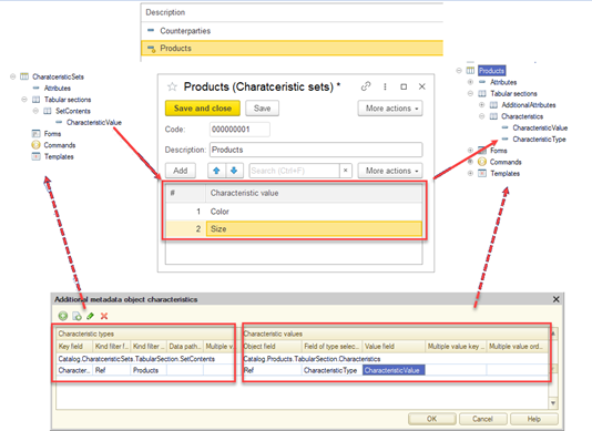
Fig. 168. Characteristics in a table. General schema
Let us review the scheme in more detail. We will use the Products catalog as an example. The chart of characteristic types is the same as in the previous examples. To store characteristic values, create a table (for example, called Characteristics) in the Products catalog. In this case, the table is similar to the information register that was used in the above examples to store the characteristic values. Create two attributes in the table:
-
CharacteristicType. Reference to the chart of characteristic types used (the ChartOfCharacteristicTypesRef.ObjectCharacteristics type). This attribute will include link to the characteristic.
-
CharacteristicValue. Value of a characteristic (the Characteristic.ObjectCharacteristics type). It stores value of one of the types of chosen as value type of characteristic type specified in the CharacteristicType attribute.
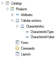
Fig. 169. Storing characteristics and their values in a catalog table
Table attribute properties are set up the same way as dimensions and register resources used to store characteristic values.
For the CharacteristicType attribute, add the CharacteristicTypesFilterObject parameter connected to the Link dimension and the Clear usage mode to the Choice parameter links property (see Choice parameter links). Search setting when choosing the characteristic type will provide display of characteristics specified in relevant predefined item of CharacteristicsSet catalog.
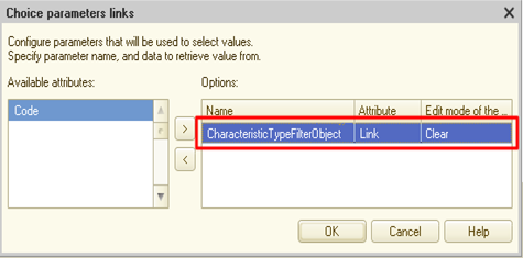
Fig. 170. CharacteristicType catalog attribute settings
For CharacteristicValue attribute, do the following:
-
Add the Filter.Owner parameter connected to the Characteristics.CharacteristicType attribute and the Clear usage mode to the Choice parameter links property (see Choice parameter links). This setting during the editing in the form will clear characteristic value when changing characteristic type.
-
The Type link property must be set to Characteristics.CharacteristicType.
Organization of storage of the used characteristics list for each metadata object (as well as the dedicated chart of characteristic types choice form) is the same as in the Example 4.
Extension
If the characteristics support is required for one more object in the example above, do the following:
-
Add the Characteristics table to the "new" object similar to the example in this section (specify all the required attribute properties).
-
Create new predefined object in CharacteristicsSet catalog.
-
For a "new" metadata object, a connection between the configuration object and CharacteristicsSet catalog (similar to the example in this section) must be set up.
-
In the chart of characteristic types choice form you must add the required filling code of the Predefined map. For example, for Contractors catalog, the added row will look as follows (predefined item of the CharacteristicsSet catalog will be called Contractors):
Predefined.Insert(Type("CatalogRef.Counterparties"), Catalogs.CharacteristicSet.Counterparties);Result
Implementation of this example will allow you to:
-
Keep the single characteristic types list for all metadata objects, which require characteristics record keeping.
-
In 1C:Enterprise mode, generate the lists of acceptable characteristic types for each metadata object.
-
Apply data access restrictions set for the data objects to restrict access to characteristic values.
5.13.3. Analytical accounting extra dimension
The chart of characteristic types allows you to organize analytical accounting based on the chart of accounts. To do this, specify, which chart of characteristic types contains extra dimension types of accounting. Then to set the specific extra dimension type only the values from the specified chart of characteristic types will be chosen. To set extra dimension types on the development stage, specify predefined values in the chart of characteristic types. If the extra dimension types are not set on the development stage, specifying predefined values is not obligatory.
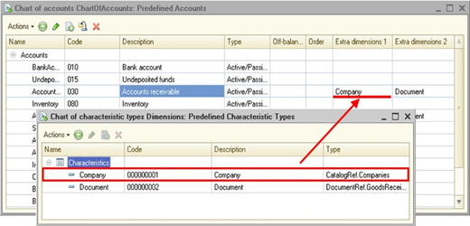
Fig. 171. Using extra dimension types
On the picture you can see that account 40 called Products output (operations, services) has two extra dimensions: ProductGroups and PriceTypes, which are chosen from the list of predefined characteristic type defined in this chart of characteristic types.
For more information on organizing analytical accounting, see Analytical accounting.
5.13.4. Using characteristics in applications
5.13.4.1. Automatically generated forms
If metadata objects involved in operations with characteristics are set considering all the recommendations above, you do not need to create additional forms to view and edit characteristic types and values (except examples 4 and 5 with manually created forms). Automatically generated forms will have the required features:
-
Object form on the navigation panel will have a command to go to the list of its characteristics.
-
Display the characteristic type list.
-
Display the characteristic value list.
-
Edit characteristic values (with automated filters and links of editable values).
Note. Note. If you select a catalog table (document and so on) as a storage object, it will not allow you to automatically generate a selection list when adding characteristics for a certain object. Such list must be generated programmatically. For an example of such generation, see Example 4.
5.13.4.2. Using characteristics in reports
Characteristics can be used in reports to:
-
Display in a report (selected fields)
-
Use in a filter
-
Use for sorting
-
Use for grouping
-
Use in conditional appearance
To use metadata object characteristics in the report, the list of available data composition scheme field must include the field with the type of link to that metadata object and usage of field attributes must not be denied for this field.
Fig. 172. Field attributes restriction
Let us look at a simple report with the Goods field of the CatalogRef.Products type. The Products catalog item has attributes and standard attributes.
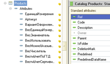
Fig. 173. Attributes and standard attributes of the Products catalog
In 1C:Enterprise mode, several characteristic types were created for this catalog.
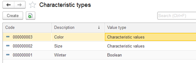
Fig. 174. Characteristic types for the Products catalog
When you need to use some characteristics (for example, Bold and Size) as the report field, the attribute list of the Goods catalog will include attributes, standard attributes, and the list of characteristic types created for the Products catalog.
Find the required characteristics type in the attributes list and add it into the list of chosen fields.
The characteristics are used in other components of the conditional appearance in the same manner (filtering, sorting, grouping, conditional appearance).
5.13.4.3. Using characteristics in dynamic lists
5.13.4.3.1. General information
Characteristics can be used in dynamic fields to:
-
Use in a filter
-
Use for sorting
-
Use for grouping
-
Use in conditional appearance
-
Display in a separate list column
The setting of dynamic list column display is performed in form setting dialog box (All actions – Edit form), while filter, sorting, grouping and conditional appearance are configured in list settings dialog box (All actions – Configure list).
Remember that characteristics in dynamic lists are usually dot-separated (in filters, groupings, and so on). However, if necessary, you can also display characteristics in the main table of a dynamic list (for details, see Including in columns).
5.13.4.3.2. Using in filters and so on.
Using characteristics to configure the list requires reference-type column for the required metadata object in the available dynamic list fields.
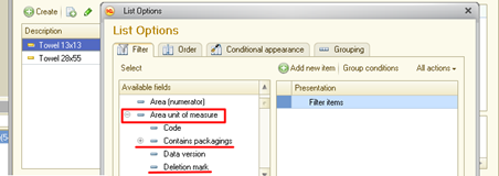
Fig. 175. Dynamic list settings
To use the characteristic value when setting the dynamic list (filter, sort and so on), do the following (in 1C:Enterprise mode):
-
Open dynamic list settings dialog box.
-
Expand the reference field (in the available fields list).
-
Choose the required characteristic to be used in the setting.
5.13.4.3.3. Including in columns
To display characteristics in dynamic list columns, include column (can be invisible) connected to reference-type data of the required metadata object.
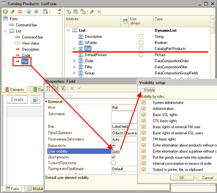
Fig. 176. Adding a dynamic list column
To add a field displaying a characteristic value, do the following (in 1C:Enterprise mode):
-
Open form setting dialog box.
-
Put a pointer on a reference-type hidden field.
-
Click Add fields.
-
Choose the required characteristic type.
Now the added characteristic types will be displayed as the dynamic list columns.
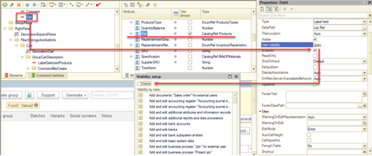
Fig. 177. Adding a column with characteristics
5.14. Registers
5.14.1. General information
1C:Enterprise registers are designed to store and process data on business or administrative activities of the enterprise.
Document and Catalog infobase objects store information on objects of subject domain, such as employees, goods, resources, and currencies. Each database object corresponds to the subject domain object.
Registers usually store information about changes in object states or other information not directly related to the objects of a subject domain. For example, registers can store information about exchange rates or receipt and consumption of goods.
A database object exists independent of its attribute values and is valued by itself. For example, an employee can change last name, ID number or any other attribute. However, it will be the same person.
After deleting, the object cannot be recreated. Even if you enter the same attributes as in the deleted object, it will be a new object. 1C:Enterprise stores an internal object identified reference. The reference is unique within the infobase. There cannot be two objects with the same reference during the infobase lifetime. The references of deleted objects are reassigned to the new objects. 1C:Enterprise allows you to store links to database objects in database fields.
The information storage unit in registers is a record. The payload of the register record is defined solely by data stored in it. For example, the record on the exchange rate by itself is worthless. It does not correspond to any object in the subject area. The important part is that it contains currency, date, and exchange rate for that date. You can remove the record and enter the same one, this will not corrupt the logic. Register records do not have links, and links to register records cannot be stored in database fields.
This section describes information registers and accumulation registers. For more information about accounting registers, see Accounting registers. For more information about calculation registers, see Calculation registers.
5.14.2. Information registers
5.14.2.1. General information on information registers
An information register is mainly intended to store data that is relevant to a business task: includes a specific combination of values, and might change with time. For example, if you want to store competitor's prices on the goods you sell, the collected prices data is expanded by goods and competitors. If you want to track price changes and enter data occasionally, the store information will also expand by time.
1C:Enterprise provides information registers to store such data and operate with them.
Information register is generally a multidimensional data array, required to implement function, which can display information using the set of arguments. The function arguments are called dimensions and function results are resources. In the example above the two-dimensional CompetitorsPrices register will contain two dimensions, Competitor and Good, and a Price resource. There can be several resources. For example, you can store wholesale and retail prices.
Apart from dimensions and resources, a set of attributes can be created for the information register. Attributes allow you to include various information in the register record. Attributes do not affect register resource values and can be used to analyze register records.
Information registers storing data that changes with time are referred to as periodic information registers. For periodic information registers, the following standard operations are supported: getting the latest or the earliest value (for example, getting the last entered price for a specific product and a specific competitor), as well as getting a slice of the latest or the earliest values. For example, all the recently entered prices for all products and competitors can be retrieved.
To expand information by time, a Period register field is used. It is not entered as a dimension but added automatically by 1C:Enterprise when creating a periodic register.
Information registers do not require to generate dimensions. In this case the register will provide a set of periodic data. Such registers can be used, for example, to store last names of officials, who sign documents. During business activities, documents are created and signed by officials, who have the right to sign document at the specific moment.
The disadvantage of such method in case of constant value change is that when opening the archive document, the new last name of the official will used that was chosen from the constant. In such cases, instead of constant use periodic information register, which stores information in changes, and in documents the values are chosen from the information register by document date.
The most representative example of one-dimensional periodic value is an exchange rate. When performing calculations (for example, when calculating price in rubles by converting from another currency), you need to know the value at the moment of calculation.
It is crucial to know the exchange rate when calculating something with the past date. In this case, an exchange rate for the past date must be "recalled".
To get such data, you need to create a table with the following columns: currency name, exchange rate date and the exchange rate itself. The rows of such table contain exchange rates of several currencies at the specific date.
| Date | Currency | Exchange rate |
|---|---|---|
| 31.10.2008 | USD | 26.5430 |
| 31.10.2008 | EUR | 35.0447 |
| 01.11.2008 | USD | 27.0981 |
| 01.11.2008 | EUR | 34.4092 |
| 02.11.2008 | USD | 27.0793 |
| 02.11.2008 | EUR | 34.4828 |
When calling such table, remember that the Exchange rate column contains specific exchange rate at the date, and it is supposed that the rate does not change until the new exchange rate appears. That is why, to get an exchange rate for an intermediate date, you need to take a rate for the closest previous date with the recorded exchange rate.
Also, keep in mind that various value in the Currency column practically means that several exchange rates are tracked. In other words, the table above can be presented in different way.
| Date | USD exchange rate | EUR exchange rate |
|---|---|---|
| 31.10.2008 | 26.5430 | 35.0447 |
| 01.11.2008 | 27.0981 | 34.4092 |
| 02.11.2008 | 27.0793 | 34.4828 |
There can be several exchange rate columns in the table (as many as the number of currencies to be tracked).
If the register is not periodic, the Period field is not created. In the example above the CompetitorsPrices register can be non-periodical, if you want to have the current prices, not just store the price changes log. In this case, the register function will be able to provide the current price for a certain product of a certain competitor. However, it will not be able to provide any information on the price this product had at the beginning of the year.
According to the described information register operation principles, there can only be one record with the specific set and a period of changes. Indeed, one product of one competitor can only have one price. If you cannot get several prices for some reason and want to enter this information into the database, create another dimension to store the value by which the prices might differ. For example, you can create InformationSources dimension. Then you will be able to enter competitors prices broken down by sources.
The uniqueness of records by dimension set is fundamentally differs information registers from accumulation registers that allow you to enter several values with the same dimension and period values.
When using a register where data is most frequently obtained for the earliest or the latest (current) points in time, it is reasonable to let 1C:Enterprise enable totals for slicing the last ones (theEnable totals for retrieving slice last property) or the first ones (the Enable totals for retrieving slice first property). As an example of such usage we can refer to a register with sale prices. The price may change with time but retrieving a current price is the most frequent request to the register.
The totals of information register will be used in case the following conditions are met:
-
Usage of totals is allowed for the register in configuration.
-
Usage of totals is allowed for the register in 1C:Enterprise mode.
-
You get the data for the first date (slice first) of the last (current) date (slice last) without specifying the period.
-
Conditions of SliceFirst and SliceLast virtual tables are only set for dimension and separator values inIndependently and simultaneously mode.
-
In data access restrictions you can only use dimensions and separators in Independently and simultaneously mode.
If all conditions are met, then to get the information form the register the regular request will be used.
5.14.2.2. Information register records
Information register rows containing information on resource values for dimension values and specific period are called records. The record key is used to identify information register records. You can enter records in information register:
-
Manually
-
Using documents
For more information on selecting record adding mode, see Editing information registers.
These two options affect the information entering method, not the main register operation logic.
The document used to enter a record into the information register is called recorder.
Recorders that are recorded independently can be edited manually or with 1C:Enterprise language means. If the dimension of such register is set as "leading" and the dimension value is a link to a database object, it is considered that the register record only makes sense while this object exists. For example, if the Competitor dimension is set as a leading dimension, it is considered that the record only makes sense as information about this competitor. When the competitor data is delete, all records about it will be deleted automatically.
If the register is recorded by the recorder, it means that records will be strictly subordinate to the recorders (documents). Usually it means that the records will be generating when the documents are posted. Hence, when the document is deleted, records are deleted automatically. As opposed to the leading dimensions, there can only be one recorder.
Remember that information register record key, created with EmptyKey() method is not the same as the information register record key with the default dimension values for "their" types.
5.14.2.3. Reading and writing data from 1C:Enterprise language
As stated earlier, an information register can be subordinate to the recorder and independent. In the first case, it is implied that in the main usage scenarios, register records are changed when posting documents, and these changes are performed from the document module, which is the recorder for our register. In the second case, it is implied that information register records can be changed in any way: interactively or using 1C:Enterprise language. In this section, you will find out how to change data of an independent information register using 1C:Enterprise language.
The information register consists of records. Each record is identified by some set of data called a record key. A record key includes the values of the information register dimensions, which allow for the unique identification of any record in the information register. In 1C:Enterprise language, the record key is represented by an object of the InformationRegisterRecordKey type:
Dimensions = New Structure;
Dimensions.Insert("Product", Catalogs.Goods.EmptyRef());
Dimensions.Insert("PriceType", Catalogs.PriceTypes.Purchasing);
RecordKey = InformationRegisters.GoodsPrices.CreateRecordKey(Dimensions);The information register allows you to change records either individually or as a set. To change one register record, use the InformationRegisterRecordManager object. The method attempts to read a single record, that is entirely determined by filter values, from the infobase. The filter is specified as dimension values of the InformationRegisterRecordManager object:
RecordManager = InformationRegisters.GoodsPrices.CreateRecordManager();
RecordManager.Period = '2019.10.30';
RecordManager.Product = Catalogs.Goods.FindByCode("000000034");
RecordManager.PriceType
= Catalogs.PriceTypes.Purchasing;
RecordManager.Read();
Result = RecordManager.Selected();The last line checks whether the information register contains the record with the specified record key values: an item with code 000000034, a purchasing price category, and date (October 30, 2019). If the record exists (and it is read with the Read() method), the Selected() method will return True. If there is no record with such record key in the infobase, the method will return the False value.
To write one record, perform approximately the same set of actions:
-
Create a record manager.
-
Set dimension values (including Period, if necessary).
-
Set resource values and, if necessary, record attributes.
-
Write a record using the Write() method of the record manager.
This set of actions in 1C:Enterprise language will be as follows:
RecordManager = InformationRegisters.GoodsPrices.CreateRecordManager();
RecordManager.Period = '2023.09.06';
RecordManager.Product = Catalogs.Goods.FindByCode("000000034");
RecordManager.PriceType
= Catalogs.PriceTypes.Purchasing;
RecordManager.Price = 5544;
RecordManager.Write();To change data in an existing record, first read the data from the infobase, then change the required values, and then save them. Remember that if there is no record in the infobase, the Selected() method of the record manager will return False. In this case, all object properties that describe dimensions, resources, and attributes will be reset to the default values (for the corresponding type), and you will need to set this data again.
The information register supports two modes of writing data:
-
Write with data replacing. Set the InformationRegisterRecordManager.Write(True); method parameter to True. The behavior in this case will depend on the record state:
-
If the record was pre-read (Selected() = True) and the key record fields were not changed (relative to the infobase data), the register record will be updated.
-
In other cases, the existing information register record will be deleted, and then the record corresponding to the data in the InformationRegisterRecordManager object will be written.
-
-
Write with data adding. Set the InformationRegisterRecordManager.Write(False); method parameter to False. In this case, an attempt to write a new record to the infobase will be made. But an attempt to make two records in the register that completely match all fields of the main filter (including Period for the periodic information register) will end with an error.
To change several records of an independent information register at once, use the InformationRegisterRecordSet object. In this case, the filter that is set for a set of records may not include values of all dimensions. As a result, there may be more than one register record in a record set.
RecordSet = InformationRegisters.GoodsPrices.CreateRecordSet();
RecordSet.Filter.PriceType.Set(Catalogs.PriceTypes.Purchasing);
RecordSet.Read();In this example, all records for which the PriceType dimension is set to Purchasing (the predefined catalog value) are read from the information register. To check whether the set is read and unedited, use the Selected() record set. The method returns True if the set is read and unedited. Otherwise (the data is not read, the set changed after reading, and so on), it returns False.
A record set is a collection. You can access its items using an index (with the [...] statement) or the For Each loop statement.
To add data to the record set, use the collection methods: Add() and Insert(). Executing the method returns an object of the InformationRegisterRecord type.
RecordSet = InformationRegisters.GoodsPrices.CreateRecordSet();
RecordSet.Filter.PriceType.Set(Catalogs.PriceTypes.Purchasing);
RecordSet.Read();
If RecordSet.Selected() Then
NewRecords = RecordSet.Add();
NewRecord.Product = Catalogs.Goods.FindByCode("000000034");
NewRecord.PriceType = Catalogs.PriceTypes.Purchasing;
NewRecord.Period = CurrentDate();
NewRecord.Price = 6000;
EndIf;To write a record set to an infobase, use the Write() method of the record set. The method parameter defines a writing method. It can take the Boolean type value or the ReplacementMode system enumeration value:
| Value | Description |
|---|---|
| True ReplacementMode.Replace | The records to be changed are determined by a record set filter. Records existing in the infobase will be deleted before the set is written. |
| False ReplacementMode.Add | The records from the set to be written will be added to the information register. If the record to be added already exists in the register (it is checked by the record key), an exception will be thrown. |
| ReplacementMode.Update | For information register records, resources and attributes will be updated for those records whose keys match the keys of records from the record set to be written. If a record set to be written contains a record with no key in the register, the record will not be added to the information register. This is the main difference from the ReplacementMode.Merge write mode. Related to the ExtendedReplacementModes record set property. |
| ReplacementMode.Merge | Supported only for an independent information register. For information register records, resources and attributes will be updated for those records whose keys match the keys of records from the record set to be written. If a record set to be written contains a record with no key in the register, the record will be just added to the information register. |
| ReplacementMode.Delete | If information register records have matching keys with the records of the record set to be written, they will be deleted from the information register. Attributes and resources can take any values. You can quickly delete a certain information register record set. Related to the ExtendedReplacementModes record set property. |
Possibility of using the Delete and Update write modes depends on the ExtendedReplacementModes property of the register record set. If this property is set to False (by default when creating a record set), you cannot use the Delete and Update modes, as well as edit the RowNumber property of the record set record. Setting the ExtendedWriteModes property to True enables these features.
Here is how combining a record set filter and keys of each set line upon writing works:
-
If a filter is set for the record set, all the set record keys must correspond to the filter in any writing mode. If the key does not match the filter, an exception will be thrown.
-
If no filter is set for a record set, the set may contain records with arbitrary key combinations. However, this feature can only be used for an independent information register.
The information register subordinate to the recorded can be written in any write mode except for ReplacementMode.Merge mode. Note that when using the Write() method of the information register record set, the True value of the Replace parameter is equivalent to the ReplacementMode.Replace value, and False is equivalent to ReplacementMode.Add.
If updating or adding records (the ReplacementMode.Update or ReplacementMode.Add write modes) results in violating the uniqueness of the information register records, this action is not performed and an exception is thrown.
When operating with the subordinate information register, you will observe the following behavior:
-
In the ReplacementMode.Update, ReplacementMode.Delete, or ReplacementMode.Add write modes, you can specify the recorder value in a register record set both in the filter and in each record of the recorded set. If the filter by recorder is set, the value from the filter is set to each record in the set before saving. If the filter is not set, each record of the set must have the set recorder value. When creating a new record set for a subordinate register, the set filter by recorder is automatically created. If such filter is not needed, disable it: RecordSet.Filter.Recorder.Set( , False);.
-
When a set is saved, the LineNumber standard attribute:
-
If ReplacementMode.Update and ReplacementMode.Delete write modes are used, it must be set for each record of the set. There must be no identical row numbers for records subordinate to the same recorder (not only in the set, but also in the infobase).
-
If the ReplacementMode.Add write mode is used, it is automatically entered into the set records based on the maximum attribute values (broken down by recorder) obtained from existing register records before saving.
-
-
When a record set is saved, the value of the Active standard attribute must be the same for all records in the set that are subordinate to the same recorder. If, after saving, register records subordinate to the same recorder have different Active attribute values, the set is not saved, and an exception is thrown.
-
When saving in the ReplacementMode.Update mode, existing records whose key field values (Recorder, LineNumber, and separators) match the records contained in the record set are updated. In this case, values of all fields except for key fields are transferred from the record set record to the corresponding register record. If there are records in the set that do not match register records, updating is not performed, and an exception is thrown.
-
When saving in the ReplacementMode.Delete mode, records whose key field values match the record set record values are deleted from the register. After deletion, the numbers of the remaining register records are updated to fill in the missing numbers. If there is no corresponding record in the register for any set record, such set record is ignored.
To read information register records, in addition to reading a record set, you can use the Select() method of the information register manager. This method allows you to select all records of the information register, or those records that correspond to the simplest filter: the "equal" condition for one dimension or attribute. The result of the Select() method is the InformationRegisterSelection object. This object provides access to all data of the information register record (dimensions, resources, attributes, internal fields), and also allows you to get the next record in the selection and the record manager (for the current record in the selection).
Filter = New Structure;
Filter.Insert("Product", Catalogs.Goods.FindByCode("000000034"));
Selection = InformationRegisters.GoodsPrices.Select(,, Filter);
While Selection.Next() Do
Message("Price = " + Selection.Price + " (" + Selection.PriceType + ")");
EndDo;Note that the Select() method works dynamically. It means that at each moment in time, the method extracts a certain portion of records from the infobase and provides access to them. After the end of a portion, the method selects a new portion and so on until the end of the information register table. As a result, the selection uses RAM very economically. At the same time, the described method of obtaining data will also transfer to the selection those data that did not exist during selection iteration (for example, the data was added from another workplace). If any algorithm requires static selection, use other tools, for example, queries.
5.14.2.4. Editing information registers
The Information registers branch of the configuration tree is used to operate information registers.
When editing a register, you need to define its properties and develop its structure: create sets of dimensions, resources, and attributes, as well as screen forms for viewing and editing register records, and (if required) print forms (see Print wizard).
This section includes description of specific information register properties that are different from the general configuration object properties.
The register is edited in Information register editing window. The register properties are located on the tabs.
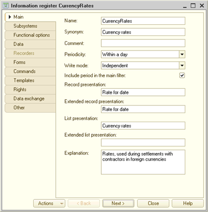
Fig. 178. Information register editor
Periodicity. This property specifies how frequently the register can save resource values that change with time.
This property determines whether values of the register resources can be retrieved using 1C:Enterprise script methods. For non-periodic register, you can only retrieve the last entered register resources value. There is no information on the past periods in such register. For periodic registers, it is impossible to retrieve a value with periodicity less than that of the register.
Periodicity does not depend on register editing method.
Write mode. The property determines the way records are written: independently (for example, manually) or depending on the recorder (for example, from documents).
If the register is set as the periodic one and independent write mode is specified, the Main filter by period property becomes available. If the checkbox is selected, then apart from the main register dimensions and attributes, participating in record filtering when registering changes, you can also specify filter by Period field.
On the Data tab, the register data structure is generated. Dimensions, resources, and attributes are created. For an independent information register, pay attention to the Type shrinking mode register dimension property. This property controls how, during an infobase restructuring, the system will handle situations where one of the following actions occurs with a dimension value type: value type change, change in a content of a union value type, type qualifier change, or any combination of the listed actions. The developer can specify one of the following values as a value of this property:
| Value | Description |
|---|---|
| Convert values | In this case, the platform converts values according to certain rules. For details, see Converting values when changing the type. When a union type is shrunk, the value of the type to be shrunk is replaced with Undefined if the type remains union after shrinking, or with the default value of the remaining type if the type becomes simple after shrinking. This value can later be replaced with a more meaningful value in the data update code. If union type shrinking is not allowed for a dimension, use other values of this property, for example, Deny. |
| Delete data | In this case, during restructuring, the record that was written broken down by dimension to be shrunk is deleted. If data loss occurs during value conversion in the shrunk dimension, causing two different values to convert into one and changing a specific value, such record will be deleted. The same applies to deleting a configuration extension that contained a type to be deleted. This behavior can be useful when the data in the register (for dimension types to be shrunk) only makes sense together with values of deleted types. |
| Deny | In this case, restructuring will be locked if the infobase contains records with values of the type to be shrunk in the current dimension, or if there is a data loss in which two different values are converted into one and a specific value changes. This behavior can be useful when you do not want any dimension value restrictions to be violated during restructuring. For example, the Deny unfilled values restriction may be violated. |
On the Recorders tab, the recorders list is managed. The tab is available if the Write mode property is set to Recorder subordinate.
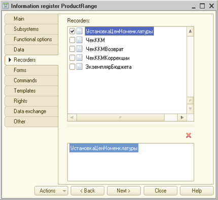
Fig. 179. Setting information register recorders
In the upper list, you can manage recorders list (select or clear the checkboxes), and in the lower list, the objects that are recorders are listed.
The recorders list for other types of registers is managed similar to the described feature to manage the information register recorder list.
The distinctive feature of information register resources is broader data typification. Resources in other types of registers can only be numerical.
For details on techniques for creating forms and templates, see Development tools.
5.14.2.5. Information register structure development
The register structure development includes creation of dimension, resource, and attribute sets.
To manage the list of dimensions, resources, and attributes of the register and edit their properties, use the controls of Dimensions, Resources, and Attribute groups of the Register editing window. In terms of settings, the controls of this group are the same. To find out how to use these controls, see Creating and deleting configuration objects.
5.14.2.5.1. Information register dimension (resource, attribute) properties
Properties of dimensions, resources and attributes are editable in the property palette. In general they are the same as configuration object properties. Further in this section, the unique properties of dimensions, resources and attributes will be described.
Type. The property defines the type of the value that will be stored in a dimension, attribute, or information register resource. If the String type is specified for an information register dimension, trailing insignificant characters in such dimension values will be removed when writing the record set. The behavior is similar to using Trim() function on the dimension value.
Leading. Set this property for dimensions with specific data type: link to configuration object. In this case, the information register record only makes sense when this object exists. When deleting the object, the associated records will be automatically deleted from the object.
Deny empty values. Selecting this checkbox enables a feature that denies writing registers with empty dimension values.
Index. This dimension property can be edited if the dimension is not leading. For dimensions, resources, and attributes with Index property set, the dedicated index is created, which improves performance when operating the register. The index is always created for leading dimensions.
When viewing the register in 1C:Enterprise mode, you can sort register records by indexed dimensions, resources, and attributes. The number of forms required to view and edit the register must be generated during configuration development.
5.14.2.5.2. Sorting information register dimension lists
The information register dimensions order is important. The dimensions, which require fast access must be located at the top of the list.
It affects the ability to apply 1C:Enterprise language methods that use position-based access to dimensions.
Also, remember that changing dimensions order required restructuring of the infobase.
5.14.3. Accumulation registers
5.14.3.1. General information
1C:Enterprise registers are used to accumulate information on the number and changes of some values tangible, financial, and other. All information about business transactions entered using documents or generated using calculations must be accumulated in registers. Then this information can be extracted, analyzed, and presented to the user as report forms.
Accumulation register is a configuration object designed to store register and totals changes. The issue that usually arises when creating a storage of summary information is to determine its structure: which sections will accumulate the summary data so that the necessary information can then be extracted without long processing. 1C:Enterprise uses simple and flexible tools to create accumulation registers. You only need to decide how you want to break down your register and what data you want to store there. 1C:Enterprise, in its turn, will ensure writing and retrieval of required data using simple language tools.
The 1C:Enterprise language methods allow you to get the accumulation register balances at a given time. You can filter by dimension values, as well as get balances broken down by other dimensions.
Consider an example. Let's say the created trade and warehouse accounting system requires storing information about the quantity and cost of each product in each warehouse. n the future, we suppose to receive information of the following type: "balance of a specific product in a specific warehouse", "balance of a specific product in total in all warehouses", "cost of all goods in a specific warehouse".
In 1C:Enterprise methodology, accumulation register of such type is the Cartesian coordinate system with warehouses on one axis and goods on the other one. The crossing of the warehouse and the product contains numbers: quantity and prices.
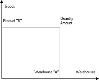
Fig. 180. Accumulation register
It is quite difficult to formulate the meaning of an accumulation register, and, most likely, it has no material equivalent.
Note. IMPORTANT. So, let us define that an accumulation register is an n-dimensional coordination system with summary data in its nodes. The axes of such coordination system will be called register dimensions and the stored data will be called register resources.
5.14.3.2. Accumulation register records
The accumulation register state usually changes with document posting. The document posting procedure is located in the document module and includes the algorithm for generating information on changes in the registers that has to be made when posting a document. This information is called register records. The totals calculation feature uses register records to make direct changes in an accumulation register. So, register records only include increments (positive or negative) of register resource values, not the value totals.
The specialist configuring the system can provide the end-user with means to view register records. Designer allows you to create screen and print forms to view and analyze register records.
When developing the configuration, you can create unlimited number of accumulation registers. However, remember that writing changes in a large number of register.
In addition to dimensions and resources, you can create a set of attributes for the accumulation register. Attributes allow you to include various additional information in the register records. Attributes do not affect values of register resources and can be used to analyze register records.
If the accumulation register records are generated in the document, the Posting event handler is used. Within this handler, all the registers for which the document can create records are "collected" in the RegisterRecords collection. Each collection element is a value of the information, accumulation, or calculation register record set type. For the document to create any records, it must add records to the record sets of the necessary registers. To do this, you can use the following code example:
Record = RegisterRecords.Inventory.Add();
Record.RecordType = AccumulationRecordType.Receipt;
Record.Period = Date;
Record.Product = CurRowGoods.Product;
Record.Warehouse = Warehouse;
Record.Count = CurRowGoods.Count;In this example, the document creates records for the Inventory register. Since the accumulation register totals (see Accumulation register totals) summarize the resource values with a particular sign, it is necessary to specify a record sign for each record of the accumulation register. This is done using the RecordType record property, which takes the value of the AccumulationRecordType system enumeration:
-
AccumulationRecordType.Receipt. Increases the total resource values by the values from the record.
-
AccumulationRecordType.Expense. Reduces the total resource values by the values from the record.
Other example lines fill in the dimensions and resources of the register: Product and Warehouse are the dimensions of the register, and Quantity is a resource. If the register has attributes, they can also be filled the same way. The Period value is a standard attribute of each information register record, which describes the date and time of the record. Other standard attributes:
-
Active. Indicates whether this record will be included in the information register totals (True, the default value) or not (False).
-
RecordType. Described above.
-
LineNumber. Contains the unique number of this record in the record set of this register made by the recorder specified in the Recorder attribute value.
-
Recorder. Contains the document that generated this record. It is filled in by the system automatically when creating records from the document.
-
ExtendedReplacementModes. Contains a flag that allows you to edit the LineNumber record property, as well as write record sets with updating or deleting set records (for details, see this section). These features are available after the property is set to True. By default, the property is set to False.
You can write a record set using the Write() 1C:Enterprise language method. This makes sense when new data in the register will be needed to correctly fill in records in other registers. In all other cases, it is better for the records to be made automatically by the system after exiting the Posting event handler (automatic record generation). Automatic generation of records has a useful property: record sets are always written in the same order, so, record tables are also locked in the same order. This avoids deadlocks when several users work concurrently.
The way in which writing will be performed depends on the Write register records on post document property:
-
Write selected. Writes record sets whose Write property is set to True in the RegisterRecords collection.
-
Write modified. Writes modified record sets. You can check whether the data of the record set was changed using the Modified() method of the record set of the corresponding register.
In addition to generating records during document posting, the 1C:Enterprise platform allows you to modify record sets outside the document. This may be required, for example, to replace a dimension or attribute value in bulk, to activate/deactivate numerous records, and in similar cases. To do it, use a record set of the corresponding accumulation register. In general, the actions performed are similar to those for the information register (see Reading and writing data from 1C:Enterprise language) and include the following steps:
-
Create a record set.
-
If necessary, set the required filters and read the data.
-
Modify the record set (including creating new records).
-
Save the set in the infobase.
There are several ways to save a set in the infobase. To do this, specify the value of the Replace parameter of the Write method of the accumulation register record set. This parameter can take a value of the Boolean type or the ReplacementMode system enumeration type:
| Value | Description |
|---|---|
| True ReplacementMode.Replace | The records to be changed are determined by a record set filter. Records existing in the infobase will be deleted before the set is written. |
| False ReplacementMode.Add | The records from the set to be written will be added to the accumulation register. If the record to be added already exists in the register (it is checked by the record key), an exception will be thrown. |
| ReplacementMode.Update | For accumulation register records, resources and attributes will be updated for those records whose keys match the keys of records from the record set to be written. If a record set to be written contains a record with no key in the register, the record will not be added to the information register. This is the main difference from the ReplacementMode.Merge write mode. Related to the ExtendedReplacementModes record set property. |
| ReplacementMode.Merge | It is not supported for an accumulation register. |
| ReplacementMode.Delete | If accumulation register records have matching keys with the records of the record set to be written, they will be deleted from the information register. Attributes and resources can take any values. You can quickly delete a certain accumulation register record set. Related to the ExtendedReplacementModes record set property. |
Here is how combining a record set filter and keys of each set line upon writing works:
-
If a filter is set for the record set, all the set record keys must correspond to the filter in any writing mode. If the key does not match the filter, an exception will be thrown.
-
If no filter is set for a record set, the set may contain records with arbitrary key combinations. However, this feature can only be used for an independent information register.
Note that when using the Write() method of the information register record set, the True value of the Replace parameter is equivalent to the ReplacementMode.Replace value, and False is equivalent to ReplacementMode.Add.
If updating or adding records (the ReplacementMode.Update or ReplacementMode.Add write modes) results in violating the uniqueness of the information register records, this action is not performed and an exception is thrown.
When operating with an accumulation register, you will observe the following behavior:
-
In the ReplacementMode.Update, ReplacementMode.Delete, or ReplacementMode.Add write modes, you can specify the recorder value in a register record set both in the filter and in each record of the recorded set. If the filter by recorder is set, the value from the filter is set to each record in the set before saving. If the filter is not set, each record of the set must have the set recorder value. When creating a new record set for an accumulation register, the set filter by recorder is automatically created. If such filter is not needed, disable it: RecordSet.Filter.Recorder.Set( , False);.
-
When a set is saved, the LineNumber standard attribute:
-
If ReplacementMode.Update and ReplacementMode.Delete write modes are used, it must be set for each record of the set. There must be no identical row numbers for records subordinate to the same recorder (not only in the set, but also in the infobase).
-
If the ReplacementMode.Add write mode is used, it is automatically entered into the set records based on the maximum attribute values (broken down by recorder) obtained from existing register records before saving.
-
-
When a record set is saved, the value of the Active standard attribute must be the same for all records in the set that are subordinate to the same recorder. If, after saving, register records subordinate to the same recorder have different Active attribute values, the set is not saved, and an exception is thrown.
-
When saving in the ReplacementMode.Update mode, existing records whose key field values (Recorder, LineNumber, and separators) match the records contained in the record set are updated. In this case, values of all fields except for key fields are transferred from the record set record to the corresponding register record. If there are records in the set that do not match register records, updating is not performed, and an exception is thrown.
-
When saving in the ReplacementMode.Delete mode, records whose key field values match the record set record values are deleted from the register. After deletion, the numbers of the remaining register records are updated to fill in the missing numbers. If there is no corresponding record in the register for any set record, such set record is ignored.
5.14.3.3. Accumulation register totals
As described above, the register changes are made with register records. Register records affect its totals. Totals is a summary register information that is retrieved by totaling values entered by register records.
The accumulation register totals can be presented as a table with as many columns as the total of dimensions and resources of accumulation register. The number of rows in accumulation register totals table will depend on the number of unique dimension values and will not depend on the number of unique resource values.
| Product | Warehouse | Count | Sum |
|---|---|---|---|
| Table | Retail | 10 | 5000 |
| Table | Wholesale | 5 | 2500 |
| Cabinet | Temporary | 7 | 10500 |
| Cabinet | Wholesale | 2 | 3000 |
| Cabinet | Retail | 10 | 15 000 |
In the table, you can see that the Product dimension takes the Table and Cabinet values, and the Warehouse dimension takes the Temporary, Wholesale, and Retail values. Count and Sum columns displaying accumulation register resources contain quantity and total of each good in each warehouse.
Unlike with register records, you cannot directly view the accumulation register totals. To call the totals, a number of reports can be created in configuration that will call the totals and display them as product reports, bin cards, invoices and so on.
5.14.3.4. Balance registers and turnover registers
There are two types of accumulation registers in 1C:Enterprise: balance registers and turnover registers.
For balance register, 1C:Enterprise language methods allow you to retrieve the accumulation register totals at the specified point in time. You can filter by dimension values, as well as get balances broken down by other dimensions.
Turnover registers are designed to store information, for which the concept of balance is pointless, for example, totals of sales broken down by customers.
Let us consider an example: AR/AP accounting with customers buying goods that the enterprise produces or sells (to service customers and so on). You can say that implementing such accounting is a must for general accounting in any enterprise.
To quickly retrieve current data on the mutual debts of the enterprise and customer, the Settlements register must be used, which stores sum of debt for each customer. With each business activity, the registry state will change accordingly reflecting the current settlements status. The AR/AP accounting register is a balance register.
However, you cannot retrieve data on some customer's purchase volume in a period from the AR/AP accounting register, as it does not store such information. That is why you need to take extra steps to get this information. For example, you can include the Counterparty attribute in the register structure, sort register records by the required counterparty, and calculate the total purchase amount. However, when you need to retrieve these data quickly (for example, when the customer reached specific purchase total, a discount must be applied), you cannot use this method.
In this case, the turnover register can be the right solution. In this register, let it be Purchase volume, the data on purchase volume for each customer is stored (the customer turnover).
From now on, each business activity will change the status of Settlements register as well as Purchase volume register. When the customer buys a product, the information of the purchase total will be added to this register. As a result, the Purchase volume register will constantly accumulate information on the overall purchase volume of the customer.
The above information will help to conclude on advantages of registers.
First of all, registers are used to store information when the quick access is required. The "promptness" and practicability of registers usage must be defined by the specialist configuring 1C:Enterprise based on the users demands.
Registers also allow you to retrieve more accurate information on the state of funds. The processes for document saving and register records writing are separated (the document can be saved without posting), so the document data and information in registers might differ. The register, as opposed to the document, is the storage for final information, so the register records are used as a proof of business activity.
5.14.3.5. Main accumulation register properties
The Accumulation registers branch of the configuration tree is used to operate accumulation registers.
Editing the properties of Accumulation register type objects and creation of the subordinate objects is performed in the editing window.
When the accumulation register is recorded, its type is defined and register structure is developed:
-
The register dimensions, resources, and attributes are created.
-
If needed, screen forms and print forms are created for viewing register records.
Note. Note.Values of theUUID, BinaryData types and strings of unlimited length cannot be used as accumulation register dimension types.
This section describes unique properties of the accumulation register that are different from the general object properties.
Register type, in case the register is designed to:
-
Store balances (choose Balances value from the list).
-
Store turnovers – Turnover value.
For a description of the difference between balance and turnover registers, see Balance registers and turnover registers.
Default list form. Several forms can be created to view register records. If there are several forms for input and selection, specify the form that will be used as the default in Default list form property.
Enable totals splitting. If this checkbox is selected to True (default value), the totals splitting feature will be used to provide better performance of concurrent register writing. When several sessions write records at the same time, 1C:Enterprise will not update the same register records. It will write totals changes separately. When retrieving totals, the values will be added. This maintains and provides accurate totals (for example, to retrieve reports quickly) and concurrent records writing. This mode requires additional resources (for example, more data in totals tables are required). That why there are properties in configuration and in the language managing this mode.
The records will be "multiplicated" only when the transaction are performed simultaneously. Their number in each record combination will depend on the maximum number of simultaneous transactions. When recalculating the totals, some records are collapsed.
The totals splitting mode can be changed by the used in 1C:Enterprise mode. The property is enabled by default.
Use in totals. If the checkbox is selected to False, the dimension is excluded from the stored register totals.
Several forms can be created to view register records. If there are several forms for input and selection, specify the form that will be used as the default in Default list form property.
5.14.3.6. Turnover accumulation register aggregates
5.14.3.6.1. Basic concepts
The aggregates feature is designed to increase the system performance when operating with turnover accumulation registers. Aggregates are dedicated storages designed to be used within 1C:Enterprise request feature. To further describe aggregates, we will use several terms explained below.
Aggregate is a physical database table, storing summary turnovers of all register resources by the chosen dimensions with the specified periodicity and in the specific period. The register, for which the aggregates are generated, might contain no more than 30 dimensions.
The aggregates have the following parameters:
-
Aggregate size is a size of the aggregate table. Estimated figure.
-
Effect is the expected reduction of the average request execution time with the help of aggregates. For example, if the aggregate effect is 90 %, it means that the average request execution time with the help of this aggregate is 90 % less than the average request execution time but using the totals. Estimated figure.
Aggregate period is a date's interval, for which the data are stored in the aggregate.
Aggregate periodicity is a periodicity of data storage in the aggregate.
Aggregates list is the set of aggregates specified on the configuration stage. The list can be created manually or uploaded form the file generated by calculating the optimal aggregates.
Usage statistics is an information on the requests (dimensions, period, periodicity) to the register. Used to rebuild the aggregate and get the optimal aggregate list.
Optimal aggregate list is a list of aggregates with optimal size to effect ratio for the current register state (its records and usage statistics).
Aggregates/totals mode. If the aggregate's mode is set, the aggregate data will be used to execute requests. If the total's mode is set, the totals data will be used to execute requests.
Aggregate usage. Disabling aggregates means that when register records are changed, no operations will be made with the aggregates. Disabling aggregates makes sense while the data are massively uploaded to the registers. However, further aggregates enabling might result in resource-demanding process of aggregates updating (in case the changed data fall into the aggregate period).
5.14.3.6.2. General aggregate operation scheme
Let us review the general aggregate operation scheme:
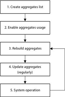
Fig. 181. General aggregate operation scheme (client/server mode)
Note. Note. This scheme describes operation of one register. If you need to operate several registers, repeat each step for every register.
Let us review the given operation scheme in more detail:
- Create the list of the required aggregates in the Designer. This step is optional. The aggregates can be created in the Designer in case you need to ensure constant use of some aggregate in the infobase.
If you decide to create aggregates in the Designer, this can be done in the following ways:
-
Calculate (for example, in totals mode) and upload optimal aggregates (DetermineOptimalAggregates() method). If the aggregates were not used before, the list of optimal aggregates will only be retrieved based on the register records table. If the aggregates were used before, the list of optimal aggregates will be generated based on the records table and usage statistics.
-
Create custom aggregate list based on the register requests analysis.
-
Enable aggregate operation mode (SetAggregatesMode() method) after updating database configuration.
-
After this you need to rebuild aggregates from time to time (RebuildAggregatesUsing() method). When executing this operation, 1C:Enterprise adds the required aggregates and deletes the unused ones. This operation is executed is the current aggregate list is not optimal. Only those aggregate are deleted that were created during rebuilding. The aggregates created in the Designer are not deleted automatically.
If the aggregates are created in the Designer, the following actions will be made when rebuilding:
-
The aggregate will be enabled if the aggregate usage mode is set to Always. Assessing aggregate performance does not affect its usage.
-
The aggregate will be enabled based on the performance assessment in case the aggregate usage mode is set to Auto. Using this aggregate is assessed along with aggregate created automatically by the 1C:Enterprise. If the automatically created aggregate is more efficient than the aggregate created in the Designer in Auto mode, the automatically created aggregate will be used.
-
Then, update the aggregates (UpdateAggregates() mode). Updating aggregates causes data to be transferred from the records table of the chosen register to the aggregate tables. The records created after the previous aggregate update are transferred.
-
Then, accumulate the usage statistics for the created aggregates. To do this, perform typical tasks using data from register with aggregate modes enabled, for some time (for example, 1 month). The aggregates must be updated regularly during operation. After this period, rebuild the aggregates (Step 3) and repeat Steps 3 – 5 on a regular basis.
The scheme above describes approach to register aggregates operation in client/server mode.
In file mode, the aggregates are operated differently:
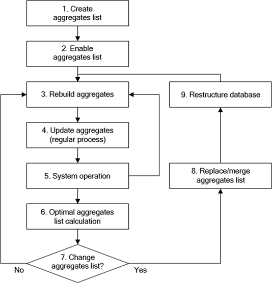
Fig. 182. General aggregate operation scheme (file mode)
The main difference of this scheme form the general aggregate operation scheme is the following (only differences are described):
-
Creating the list of aggregates in the Designer on Step 1 is compulsory.
-
Step 6. Recalculation of the optimal aggregates (DetermineOptimalAggregates() method) must be done regularly (for example, once per month). During this period (1 month), perform typical tasks using data from register with aggregate modes enabled. The aggregates must be updated regularly during operation.
-
Step 7. After getting the new list of optimal aggregates, you need to define, whether changing aggregate list in configuration metadata is required. If the change is not required, then continue operation and go to Step 3.
-
Step 8. If the aggregate list requires updating, upload the required (or all) aggregates (from the list of optimal aggregates). Then update database configuration (the infobase will be restructured) and continue with Step 3.
Recommendations on every step are described in the next section.
5.14.3.6.3. Recommendations on how to use aggregates
Generating aggregates list
The aggregate list can be generated in several ways. If you plan to enable aggregates for the register that already exists in the configuration in case the aggregates usage is not enabled for it, there are several ways to do this:
-
If there are no register records or there are a few of them (no more than 2 or 3 thousand records), analyze the requests, which use the chosen register and retrieve a list of frequently used combinations of dimensions, filter, request periods and periodicity of data retrieval. Use the retrieved information to create aggregate list and try to minimize a number of aggregates used.
-
If there are a large number of records in the register (more than 3 thousand), calculate the optimal aggregates using the register data with DetermineOptimalAggregates() method and upload the resulting aggregate list.
If the aggregate usage and aggregate mode are enabled for the used register (that is, the initial aggregate list was somehow generated), you can retrieve the list of optimal aggregates and import it in Designer. The difference between this method and the second method is that in this case to calculate optimal aggregates, the system statistics will be used. That is why, the retrieved aggregates list will be more efficient than retrieving the list of optimal aggregates for the register without aggregate modes and aggregate usage enabled.
Note. Note. Retrieving optimal aggregates only makes sense if there are 3 to 5 thousand records in the register. If there are less records, the generated aggregate list might be inefficient.
Rebuilding
The aggregate rebuilding operation must be done as frequently as the optimal aggregate list calculation. This operation does not imply changes in the aggregate list and only uses the current aggregates.
Remember that the rebuilding operation is productive if the volume of accumulated statistical data used is large enough.
However, it is hard to give general recommendation in the rebuilding period, but we can distinguish several aspects:
-
The register data behavior might change.
-
You suppose that the request nature will change (this will result in changes in accumulated statistics).
Two parameters must be specified when executing this operation:
-
Maximum Relative Size sets limits for the generated aggregate list (in percents of the records table). If the parameter is equal to 0, there are no limitations of aggregates size.
-
The minimum effect of rebuilding is a required number of percents in increase resulted from old list rebuilding. If the effect of the new list is increased by the set value, it means that the method actually rebuilds the list. If the parameter is not set or set to 0, it means that there were no minimal effect requirements.
Also, the current aggregate list is rebuilt if it is greater than the Maximum relative size parameter or the list was rebuilt with efficiency that is larger by at least the Minimum effect parameter value. Otherwise, the aggregate list is not rebuilt.
Note. Note. The rebuilding operation takes quite a lot of time and resources. It is not recommended to complete it when other users actively operate with the infobase.
Aggregate updating operations
It is recommended to perform this operation more often than the aggregate rebuilding.
The are two ways to update aggregates:
-
Update all aggregates marked as used in full. This might take a significant period of time.
-
The "partial" filling. In this case, with each call the period of 1 month is updated in 10 aggregates.
When performing this operation, specify Maximum relative size parameter. It limits the size of the generated aggregate list (in percentage from the records table). If the parameter is equal to 0, there are no limitations of aggregates size.
Note. Note. It is better to perform this operation when the infobase load is low.
Note. Tip. We recommend to use totals splitting mode when using the aggregates, especially if the aggregates are updated using the scheduled job while posting many documents associated with the register, for which the aggregates are updated.
Using aggregates
To set the aggregate used for request, the below described algorithm is used.
The used dimensions of the register are defined in the request. Then the list of aggregates, which contain all dimensions used and correspond to the request in periodicity and period, is generated. The aggregate with minimum size is chosen from this list. This is the aggregate that will be used.
A request may contain the aggregate with lesser periodicity than the request requires. In this case the data will be retrieved by combining all data from lesser periods.
The period set in the request might not correspond to the aggregate period. In this case two aggregates can be used to complete the request. Consider an example. There are two aggregates closing the whole request period in the infobase:
-
With monthly periodicity
-
With daily periodicity.
The request is performed from September 15 to November 15. In this case, two aggregates will be used:
-
The aggregate with monthly periodicity will be used to retrieve data from October 1 to October 31.
-
The aggregate with daily periodicity will be used to retrieve data from September 15 to September 30 and November 1 to November 15.
-
The data of different aggregates will be combined to get the final result.
The virtual table with turnovers of the register, for which the aggregates mode is enabled, always contains current data.
Calculating optimal aggregates
This operation may be performed when required and not on a regular basis. Below is the list of scenarios, which require the calculation of optimal aggregates:
-
When the initial aggregate list generation period has expired.
-
In case of significant decrease of performance in the current aggregate list.
-
In case of significant change of the data nature.
-
When the register requests content changes.
-
If there is a probability that the current aggregate list is no longer optimal.
Note. Note 1. This operation is not compulsory for client/server mode. Generating optimal aggregates (when required) is made automatically during aggregates rebuilding.
Note. Note 2. This operation requires the most resources and time. It is strongly recommended to perform it when other users do not operate with the system.
Using scheduled jobs when operating aggregates
Aggregate rebuilding and updating operations can be performed using the scheduled jobs. When creating a schedule for scheduled jobs, adhere to the following recommendations:
-
For a scheduled job performing rebuilding and updating, it is recommended that you fill the Key property of the scheduled job (see Scheduled jobs).
-
It is recommended to set the updating and rebuilding schedule for scheduled jobs to avoid simultaneous updating and rebuilding.
Keep the recommendations above to avoid concurrent rebuilding and updating and enhance performance.
5.14.3.6.4. Editing aggregates
You can create and edit the aggregate list only for turnover accumulation register. The Register type property is set to Turnovers. To call the aggregate wizard, use Open aggregates command in the context menu of the register.
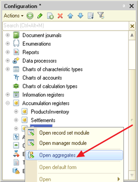
Fig. 183. Calling aggregate wizard
The aggregate wizard window will open, where you will be able to manage turnover accumulation register aggregates. You can manage aggregates manually. Also, you can import them from the predefined list of optimal aggregates. To do it, use the dedicated command bar button.
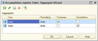
Fig. 184. Aggregate wizard
When creating aggregates, a usage mode can be set. If the usage mode is set to Auto (by default), 1C:Enterprise will automatically define, whether the aggregate must be used when rebuilding aggregates. If it is set to Always, 1C:Enterprise will always use the aggregate.
The Periodicity column defines the minimum period of time for storing totals of the chosen dimensions. There can be several aggregates with the same set of dimensions but different periodicity. Do not generate too much aggregates. A large number of aggregates can result in excessive database size, but it will not improve the request performance.
In the right part of the window you can set, which dimensions are included into the edited aggregate. An aggregate can include any number of dimensions (no more than 30) or do not include any. In this case 1C:Enterprise stores free register turnovers with the set periodicity.
If there is an XML file with the list of optimal aggregates, it can be uploaded. To do this, use the aggregate wizard command and choose the file.
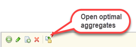
Fig. 185. Uploading optimal aggregates list
1C:Enterprise will compare the aggregates from the list and the current list of aggregates. It will highlight the aggregates that are recommended for adding (from the Optimal aggregates list) and aggregates that are recommended for deleting (Aggregates list). The recommendations are not mandatory and can be followed partially.
5.14.3.7. Accumulation register structure development
The structure development is creating sets of dimensions, resources, and attributes on the Data tab (see Object editing window).
5.14.3.7.1. Accumulation register dimension (resource, attribute) properties
Properties of dimensions, resources and attributes are editable in the property palette. In general, they are the same as object properties. Further in this section, the unique properties of dimensions, resources and attributes will be described.
Type. As opposed to the dimensions and attributes, Resource type objects can only store one type of data: Number.
Deny unfilled values. Selecting this checkbox for the dimension enables a feature that denies writing the register record with an empty dimension value.
Index. This property can only be set for dimensions. Setting this property allows you to speed up the operations that call the register data, for example, if you select register records by a specific dimension value. Such operations include requests with condition of equality of the current dimension and the specified value, as well as temporary calculation and 1C:Enterprise language methods to cycle AccumulationRegister object records that use filtering by the specific dimension value.
Use in totals. If the property is not set, the dimensions are excluded from the stored register totals (the property is only used for the stored turnover register dimensions). In case such dimension is used in request of virtual table condition, the virtual table will not use the stored totals and will calculate data using the records table.
5.14.3.7.2. Sorting accumulation register dimension lists
The order of accumulation register dimensions affects optimization of access to the register totals. Dimensions that require quick access must be placed at the beginning of dimension list.
Chapter 6. Command interface
Command interface is the main way of user access to the application features. It allows users to navigate between forms and perform various actions. The configuration developer does not write detailed commands of the global interface and form command bar for each role implemented in the application (or combination of such roles). Instead, the developer writes the rules under which the command interface will be automatically generated for the user.
Such declarative description of the command interface helps to align commands available for the user and user rights. It also helps to modify the application command interface upon partial implementation of application features.
6.1. General command interface structure
6.1.1. Sections and subsections of the main application window
All global commands of the main application window are divided into sections. The user navigates between sections using the sections panel. Sections in the panel are explicitly defined by the upper-level subsystems whose Include in command interface checkbox is selected.
The current section commands are displayed in the navigation panel and actions panel of the main window.
When commands of a certain section are displayed, one or several subsections might appear in the navigation panel. Subsection is a set of commands that correspond to a subordinate subsystem whose Include in the command interface checkbox is also selected. For example, the Sales records section might include the Retail and Wholesale subsections due to existence of respective subordinate subsystems.
6.1.2. Types of commands
The user command interface can be divided into:
-
Independent global commands
-
Parameterizable global commands
-
Local form commands
This section covers only global commands. For the local form commands, see Form commands. Commands can also be divided into:
-
Standard commands (automatically added by 1C:Enterprise to the command interface)
-
Navigation commands
-
Action commands
-
Commands created in the configuration
6.1.2.1. Standard commands
For most configuration objects, 1C:Enterprise provides standard commands automatically placed in the command interface. Such objects and standard commands provided by 1C:Enterprise are listed below:
-
Common form:
- Open common form
-
Constants:
- Open constant editing form
-
Catalogs:
-
Open list form
-
Open new form
-
Open new group form
-
Generate
-
Go to list filtered by owner
-
-
Documents:
-
Open list form
-
Open new form
-
Generate
-
-
Document journals:
- Open list form
-
Reports:
- Open default form
-
Data processors:
- Open default form
-
Chart of characteristic types:
-
Open list form
-
Open new form
-
Open new group form
-
Generate
-
-
Charts of accounts:
§ Open list form
§ Open new form
§ Generate
-
Charts of calculation types:
-
Open list form
-
Open new form
-
Generate
-
-
Enumerations:
- Open list form
-
Information registers:
-
Open list form
-
Open new form
-
Go to list filtered by recorder
-
-
Accumulation registers:
-
Open list form
-
Go to list filtered by recorder
-
-
Accounting registers:
-
Open list form
-
Go to list filtered by recorder
-
-
Calculation registers:
-
Open list form
-
Go to list filtered by recorder
-
-
Business processes:
-
Open list form
-
Open new form
-
Generate
-
Go to task list filtered by business process
-
-
Tasks:
-
Open list form
-
Open new form
-
Generate
-
-
Exchange plans:
-
Open list form
-
Open new form
-
Generate
-
-
Filter criteria:
- Open list form
6.1.2.1.1. Generating and placing standard commands
Standard commands that open the list form and create a new item are always generated if the Use standard commands property is not disabled.
The standard report command is generated if the report has the main data composition schema or main/additional form specified.
The standard processing command is generated if processing has a main or additional form specified.
The standard generation commands are created by 1C:Enterprise if the Generate property is properly set. For example, if the Purchase invoice and Sales invoice documents can be generated from the Goods and Goods batches catalogs, the standard generation command will appear for these catalogs.
Standard commands that open a list form filtered by owner are generated when the Owners catalog property is set in particular way and there is one or several dimensions with the Leading flag for an information register.
The standard list form command filtered by recorder is generated for registers subordinate to the recorder.
Standard commands are located in the following way:
| Panel | Commands located |
|---|---|
| Navigation panel | List opening commands |
| Actions panel | · Commands for opening the constant editing form · Commands for opening new object forms · Commands for opening forms of reports and data processors |
| Form navigation panel | Commands for opening filtered list forms |
| Form command bar | Generation commands |
6.1.2.1.2. Parameterizable standard commands
Some standard commands are parameterized and can be executed in the context of a form after getting some value as a parameter.
| Command | Parameter type |
|---|---|
| Generate | Reference to a source object |
| Open list filtered by owner | Reference to an owner object |
| Open list filtered by recorder | Reference to a recorder document |
| Open filter criteria list | Reference to filter criterion value |
For more information on how to generate a parameter type of standard parameterizable commands, see Command parameterization.
If you can use the Goods catalog and the Goods batches catalog to enter the Invoice document, the generation command parameter type will be union: CatalogRef.Goods and CatalogRef.GoodsBatches. This is why the Generate purchase invoice standard command will be automatically placed in the item forms of goods and goods batches catalogs.
6.1.2.2. Independent and parameterizable global commands
Use Independent global commands to select features for the whole application. To execute such command, you do not need any additional information (parameters). Command examples:
-
Open catalog list
-
Open document journal
-
Open report form
-
Open new catalog item form, and so on.
Parameterizable global commands depend on the execution context and cannot be executed without getting additional information (command execution parameter). Command examples:
-
Open list of subordinate catalog (parameter is reference to owner catalog item)
-
Open record list of register subordinate to another recorder (parameter is reference to recorder document)
-
Generate object (parameter is source object)
Parameterizable commands can be displayed in the auxiliary window navigation panel and directly in the form command bar.
Global commands are displayed in the form command bar before the Open help command. Commands from the Important group are located directly in the command bar. Other command groups such as the Generate standard command and other groups from the Form command bar category are displayed in the submenu. Execution of global commands located in the form command bar opens a new auxiliary window of the application.
Remember that global commands do not process the Check property. This property is used by form commands only (see Form commands).
6.1.2.3. Navigation commands and action commands
Navigation commands redirect users to another application form without leaving the current (main or auxiliary) application window. A navigation command opens another form in the same application window where the user has called this command.
Both independent commands of the global command interface and parameterizable global commands can be navigation commands. Navigation commands are located in the navigation panel of the main or auxiliary application window.
The examples of navigation commands in the main application window: go to catalog list or go to document journal. For example, the Currencies command opens the currency list form in the same window, but the Financial documents command opens the document list form in the same window.
The examples of navigation commands in the auxiliary application window: go to lists that are logically subordinate to the object edited in this window. For example, the editing form of a currency catalog item can include a command redirecting the user to the information register with exchange rate history. A document form can include a command redirecting the user to some register records.
Note. Note. Navigation command execution is not canceled if the user refuses to open a form. In this case, an empty form will be opened instead.
Action commands open a new auxiliary application window upon their execution. Such commands replace the user's active task for some time. By doing that, they significantly change the user's operation context. For example, the command that creates a new document changes the user's active task from application navigation, which is executed in the main application window, to creation of a new document.
You can find such commands in the actions panel of the main application window or in the form command bar displayed in the auxiliary application window.
6.1.2.4. Commands created in the configuration
In addition to standard commands, configuration developers can create their own commands, define their locations (command group), describe actions to be performed by commands in 1C:Enterprise language, and so on.
For more information on the Command object properties, see Common commands and Commands.
6.1.3. Command groups
All global commands can be divided into four categories in terms of their location and nature.
| Category | Description |
|---|---|
| Navigation panel | For placing independent navigation commands |
| Form navigation panel | For placing parameterizable navigation commands that are called from the form |
| Actions panel | For placing commands that open a new auxiliary application window |
| Form command bar | For placing parameterizable commands that open a new auxiliary application window |
The above-mentioned categories represent application interface locations where global commands can be displayed.
1C:Enterprise uses standard command groups to group global commands.
| Location | Standard group commands |
|---|---|
| Navigation panel | · Important · Regular · See also |
| Actions panel | · Create · Reports · Service |
| Form navigation panel | · Important · Go to · See also |
| Form command bar | · Important · Generate |
Moreover, when developing a configuration, the developer can create custom command groups (General – Command groups). Such groups can be classified into one of the above-mentioned categories (the Category command group property). These groups, along with predefined groups, can serve as a location for developed commands.
6.2. Global command interface structure
This section covers configuration objects and their properties that affect the configuration command interface structure.
6.2.1. Subsystems
The configuration subsystems structure establishes the basis of the global command interface in the main application window. Subsystems shape the user's understanding of the application features. The subsystems structure describes the general features to the user. Therefore, building the global command interface of the main application window based on the subsystems structure imposes some responsibility on the developer during the subsystem development. In fact, the subsystems structure is the first thing that users see when they get familiar with the application.
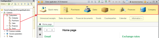
Fig. 186. Displaying subsystems in sections
The command interface structure is affected by the subsystems whose Include in the command interface property is set. This property is set for subsystems by default. So, one of the main goals of subsystems is to describe the global command interface. If there is not a single subsystem whose Include in the command interface property is set, the sections panel is not displayed in the main application window.
First-level subsystems create sections in the application. Each section is a set of specifically oriented global commands. Sections are displayed in the sections panel of the main application window. Selecting a section changes commands of the navigation panel and actions panel.
Lower-level subsystems create subsections in the navigation panel. Subsections include commands of a respective subsystem.
Whether an object belongs to a certain subsystem set defines the object commands that will be displayed in the respective sections of the configuration command interface. However, new objects do not belong to any subsystem by default. This means that object commands are not present in the command interface. This is why, to place standard and custom object commands into respective command interface sections, the developer must specify the subsystems to which the object belongs.
The object's attachment to different subsystems is independent. So, an object can belong to parent and subordinate subsystems at the same time. It can also belong only to a subordinate subsystem if it is reasonable for command interface creation.
If a configuration does not have any subsystems whose Include in the command interface property is set, all the commands that could be added there manually are moved to the desktop. In this case, the appearance of the desktop command interface editor changes: there is no command tree and there is no option to delete the command from the desktop.
As soon as there is at least one subsystem in the command interface, commands are no longer automatically added to the home page. After that, commands must be included in the interface manually.
Note. Note. Automatic addition of all commands to the home page is disabled in the Ordinary application configuration startup mode.
When building the sections panel, all first-level subsystems to be used must meet the requirements below:
-
The Include in the command interface property is set to True.
-
Access rights (see Access rights description) provide subsystem availability for the current user.
-
The subsystem is not disabled by functional options.
-
The subsystem is not disabled by the user via the setup dialog box of the sections panel.
If all commands in a section are unavailable for the user due to insufficient access rights or commands disabled by functional options/user settings, such section is still displayed in the sections panel.
6.2.2. Commands
As have been mentioned earlier, there are standard commands provided by the system automatically and custom commands created by the developer.
The Command configuration object can be created as a subordinate object for the following configuration objects:
-
Catalogs
-
Documents
-
Document journals
-
Reports
-
Data processors
-
Charts of characteristic types
-
Enumerations
-
Charts of accounts
-
Charts of calculation types
-
Information registers
-
Accumulation registers
-
Accounting registers
-
Calculation registers
-
Business processes
-
Tasks
-
Exchange plans
-
Filter criteria
You can also create common commands (Common > Common commands, see Common commands).
6.2.3. Command parameterization
If a command is parameterizable, its execution assumes getting some value as a parameter. Such value can be taken only from form data.
Note. Important. Setting a command parameter value type is only rational for the commands located in forms and which belong to the Form command bar or Form navigation panel category groups.
The Command parameter type property sets the content of the forms within which the command can be executed. For example, if a command has the CatalogRef.Goods parameter type, it can be executed:
-
In an item form of the Goods catalog where the parameter is a reference to the object being edited in the form
-
In a list form of the Goods catalog where the parameter is a reference from the current list row
-
In a purchase invoice form where the parameter is a reference to a product from the current row of the document table, and so on
The Parameter usage mode property defines the number of values of the selected type that will be passed to the command as parameter values. If this property is set to Single, one value of the selected type is passed to the command.
If the property is set to Multiple, a value array is passed as a parameter even if only one value is selected. Using this mode is reasonable when the data source for the command can be a table with multiple selection. In this case, the first array element will be the current row regardless of the table row selection sequence. For example, we have a list of goods that consists of Mixer, Vacuum cleaner, Fridge, and Kettle. If you select Mixer, Fridge, and Kettle and the current row is Fridge, the command will get an array of elements in the following order: Fridge, Mixer, and Kettle. The order of elements after the first one is not defined despite the order provided in the example.
Note. Note. If the current row is not selected, the first array element cannot be explicitly identified.
If several tables linked to the same form attribute of type DynamicList are placed on a managed form, it is undefined which table’s data will be used for command parameterization.
Command interface sections are generated automatically based on the main attribute type. When editing a form, the form developer can add something to a command interface section. For example, if a form is used for product editing, it automatically includes all commands with the CatalogRef.Goods parameter type. For example, Print product card, Go to price list, and so on. If a product has the Manufacturer attribute, commands with the CatalogRef.Counterparty parameter type can be included in the editable form as well. For example, Counterparty card, Counterparty contract, and so on. It is possible because you can get a value for parameters of such commands in the form. Such commands, which are not associated with the main attribute, are not included in the command interface automatically, but the developer can include them using the form editor.
The catalog group (Folder and item hierarchy type) and hierarchical chart of characteristic types are not automatically included in the command interface of the parameterizable global command group form. However, the developer can include such commands in the command interface using the form editor.
6.2.4. Creating default command interface
Command location depends on the Command parameter type and Group properties and on the subsystem this command (or parent object) belongs to.
Independent (not parameterizable) commands belong to the global command interface sections that correspond to subsystems including an owner object or the command itself (for common commands).
Parameterizable commands belong to the global command interface sections that correspond to the objects whose types are set in the Type property of the command parameter.
In both cases, the command group is a peculiar specification of command location within one section. For example, command groups specify the panel (navigation or action) where independent commands of a section will be located. For parameterizable commands, the command group defines whether the command will be located in the form navigation panel or form command bar.
Therefore, for independent commands (commands that do not require parameter, for example opening a list or opening a new object form), the ability to be placed by default in a category other than navigation panel or actions panel is rarely relevant. Placing parameterizable commands in the navigation panel or actions panel is pointless since such commands cannot get parameters required for their execution in the main application window context. The command placement table is shown below.
| Independent commands | Parameterizable commands | |
| Navigation commands | Navigation panel | Form navigation panel |
| Action commands | Actions panel | Form command bar |
Remember that by default global commands are not located in the group form command interface of hierarchical catalogs and charts of characteristic types. To make a global command available in the command interface of such form, the command must be placed there manually using the form editor.
When generating a command interface, text presentations of configuration objects and commands are used. The system generates presentations based on the Synonym and Name properties by default. However, you can impact this presentation. List and object presentations are used for this. For details, see Metadata object presentation.
6.2.5. Command interface property
Use the Command interface (for subsystems), Command interface (for configuration), and Main section command interface (for configuration) properties to edit global commands of respective section or commands of the main section. Edit these properties if the default command order, command groups, or command visibility do not meet user requirements.
In different sections, the same command can be displayed in different places on the navigation panel or actions panel and can have different default visibility. For example, a command for opening the Goods catalog list is important and frequently used in the Trade section. So, the developer can place it in the Important group. However, in the Accounting section, it is not that important. So, the developer can place it in the See also group.
6.2.6. Editing command set
In addition to editing the Command interface property, the editor of this property allows you to edit the command set of all sections in the All subsystems editor (see "All subsystems" editor).
You can edit the set of global commands to be displayed in the form editor on the Command interface tab (see Form editor).
6.2.7. Default role-based setup of command visibility
When section commands and form commands are created automatically, the following default visibility is set.
Visible by default:
-
Commands for opening lists of catalogs, documents, document journals, charts of characteristic types, charts of calculation types, charts of accounts, independent information registers, business processes, tasks, and exchange plans
-
Commands for opening forms of reports and data processors
-
Commands for opening the constant editing form
-
Commands for navigation to the list of a subordinate catalog
-
Commands for navigation to the list of a logically subordinate information register (register with "leading" dimensions)
-
Generation commands
-
Arbitrary commands created by the developer in the configuration process
Invisible by default:
-
Commands for opening lists of enumerations, information registers subordinate to the recorder, accumulation registers, accounting registers, and calculation registers
-
Commands for opening new object forms and new group forms
-
Commands for navigation to lists of subordinate registers
-
Commands for navigation to filter criteria lists
The visibility values created by 1C:Enterprise automatically can be changed both for parameterizable and independent commands. The default visibility value can be set broken down by roles used in the configuration. When displaying commands in 1C:Enterprise mode, a command will be visible by default if the visibility of this command is enabled for at least one user role.
When you edit role-based visibility, remember that command visibility for a role is only enabled when the command is available for this role. Therefore, when you set up visibility for a role that is highly restricted in rights, hiding commands manually by disabling their default visibility is rarely required. Besides, the total number of commands available in one or another section is rather small.
Editing of default role-based visibility is a tool that allows you to configure the initial "fullness" of the global command interface, primarily for users with extensive access rights.
6.3. Service options for navigation
6.3.1. URLs
6.3.1.1. Interactive operations
In 1C:Enterprise, you can get a text link to any command interface section, report, data processor, or infobase objects: documents, catalog items, and so on. Such link is called a URL. Use URLs to quickly navigate to the required place in the system, save user actions in the favorites list, transfer to another user, on mobile devices, and so on.
To interactively get a URL to the used application object, click Service and settings and then click Get link, or click a special form button next to the form menu. To get a link to the current object, press Ctrl + F11.
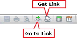
Fig. 187. Commands for getting a URL
If you call the command to get a URL, the following dialog box appears:
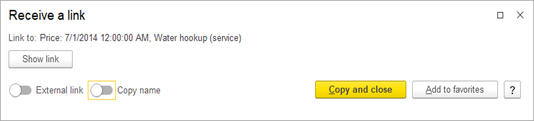
Fig. 188. Dialog box to get a link
This dialog box shows the object to which the link will redirect the user (the Link to field). Here you can also:
-
When you click Show link, an input field is generated instead of the hyperlink. The field displays the text of the URL with which this dialog box operates.
-
Convert a URL to an external one. To do this, use the External link segmented button. The infobase address is prefixed to the in-app link.
-
Use the Copy name segmented button to add a presentation of this link to the copied link. The resulting link will look as follows:
-
In-app link: Sale 000000012 dated 04/28/2008 10:54:24: e1cib/data/Document.GoodsConsumption?ref=8ca0000d8843cd1b11dc8d043d710081.
-
External link: Sale 000000012 dated 04/28/2008 10:54:24: e1c://server/srv-name/db-name#e1cib/data/Document.GoodsConsumption?ref=8ca0000d8843cd1b11dc8d043d710081.
-
To separate the presentation and link text, you can try to use the :e1c string.
-
-
Copy the URL to the clipboard and close the dialog box. To do this, click Copy and close, which is the default command in this dialog box.
-
Add the current URL to the favorites list of the current user. To do this, click Add to favorites. The dialog box does not close after that.
After you click Show link, the dialog box looks as follows:
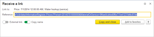
Fig. 189. URL display
You can save a link or share it with other users to refer to a certain application object. Links are plain text, which can be seamlessly shared over email, instant messengers, or cloud services. For the link format details, see URL formats. You cannot get a URL to standard functions. So, you cannot place standard functions in favorites. To quickly call standard functions, use the global search field. For more information, see Global search plan.
To start a client application while opening the object encoded in the link, you can use a URL. If an infobase is published on a web server, you can get an external URL. This link will be a standard URL that you can enter in the web browser address bar.
Note. Note. In Microsoft Internet Explorer, the application is not loaded when you follow a link if this link refers to the application loaded in the current web browser window. It is recommended that you paste a link in the address bar of a new blank web browser window.
If you need to use a thin client, you can use the URL as the value of theURL command of the command line of the client application startup. More details about following the URL using the URL parameter.
There are situations when you can get multiple URLs in one application form. In this case, you can select the link to receive in the dialog box to get a URL. For example, in the Stock balance report, the Main option is selected and some settings are configured. When you try to get a URL, the following dialog box will appear:
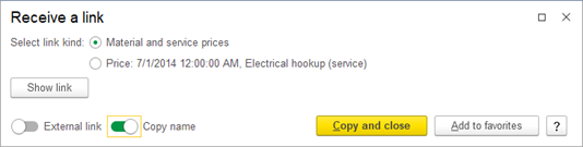
Fig. 190. Getting multiple URL types
The required URL will be generated depending on the selected kind. The dialog box appearance (in terms of provided link kind options) depends on the form where the dialog box for getting a URL is called.
When you add a URL to the favorites list, the dialog box will look a little different.
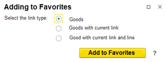
Fig. 191. Adding to favorites
You cannot get an external link and view the URL in this dialog box. All the other dialog box features match the ones of the dialog box for getting a URL.
6.3.1.2. Using from 1C:Enterprise language
In 1C:Enterprise, you can also generate a URL programmatically. To do it, use the GetURL…() method family. Use the GetURL() method to get the required URL for any configuration object that supports getting a URL. There are specialized methods in client application form extensions. These methods get a URL for the main form attribute. Use the GetInfoBaseURL() method to get the infobase address for generating an external URL based on an internal one (similar to the External link segmented button in the dialog box to get a link).
A feature of methods for getting URLs is that you can pass a parameter list to the form to open. To do this, use the URLExternalData parameter in the GetURL…() methods. This parameter is a structure that is placed in the storage of external URL parameters. Its address is placed in the URL as the extdata parameter value.
If the extdata parameter is found in the URL when you open the form:
-
A form is created and all required default parameters are filled for the form.
-
A parameter structure is received from the external URL data storage.
-
The parameters are transferred from the restored structure to the Parameters collection of the form to open. Each "key-value" pair from the structure is a separate parameter of the Parameters collection.
-
The form opens with a new parameter set.
When you call a command using a URL, the parameters that are passed through the external URL data storage get into the command handler (the CommandProcessing() method) as the value of the Parameters property of the CommandExecuteParameters parameter.
6.3.1.3. Actions when getting a link and adding to favorites
When a user executes a command for getting a URL or adding a URL to user favorites in a form, the platform calls several event handlers of this form in the dialog box for getting a link. The main difference between the dialog boxes is that in the dialog box for adding to favorites, you cannot get a URL to a table object displaying a dynamic list, generate an external link, and view the generated link. The general procedure for getting a URL is as follows:
-
The handlers for getting the URL list are called sequentially (URLListGetProcessing()). If the active form item is a table that displays a dynamic list of objects that support getting a URL, the handler of this table is called first. Then, the platform generates a default URL list for the current form. The list of URLs received from the table handler is added to the end of the default list. After that, the event handler is always called for the form in which the URL is received. The form event handler gets the URL list that was received during the previous actions.
-
In each of the specified handlers, the developer can delete and add list items. In the form event handler, the URL list will include links generated by the platform and links received after completion of the form table event handler. After the URL list is generated, the user needs to select a URL from it.
-
A selection dialog box where the user can do it is displayed. The list displays all URLs that were generated by previous handlers for getting the URL list.
-
The user selects a URL.
-
The handler for getting a URL is called (URLGetProcessing()). The handler to call depends on where the URL selected by the user is obtained from: from the dynamic list table or from the form. Accordingly, a table handler or a form handler can be called. The handler completion result is used by the system for further actions.
Let us look at different aspects of the general procedure in more detail. The URL list is stored in the URLChoiseList object, which is a collection of the URLChoiceListItemDescription objects. The choice list item description consists of the following properties:
-
Key. The value that is used to uniquely identify a URL in the list.
-
Presentation. The URL presentation in the dialog box for getting a link.
-
RequestUserPresentation. If set to True, the user can specify their own presentation for the URL to be displayed in favorites and used to save external link data. If this property is set to False, the value of the RequestUserPresentation will be used as the presentation.
When you call the event handler for getting the URL list, the platform generates a default URL list. In this list, any value of the FormStandardURLVariant system enumeration is used as a key. The created list depends on the called event. If the event is called for a table, the list content depends on the AllowGettingCurrentRowURL table property. If this property is cleared, the list will be empty. If the property is set to True, the list will consist of the following items:
-
First item:
-
Key: FormStandardURLVariant.ListCurrentRowObject or FormStandardURLVariant.ListCurrentRowRecord.
-
Presentation: presentation of the URL of the current dynamic list row.
-
Request the user presentation: no.
-
If the event is called for a form, the list will consist of the following items:
-
If the form is a dynamic list form, the list consists of the following items:
-
First item:
-
Key: FormStandardURLVariant.List.
-
Presentation: <list presentation>.
-
Request the user presentation: no.
-
-
Second item:
-
Key: FormStandardURLVariant.ListWithCurrentSettings.
-
Presentation: <list presentation> with the current settings.
-
Request the user presentation: yes.
-
-
Third item:
-
Key: FormStandardURLVariant.ListWithCurrentSettingsAndRow.
-
Presentation: <list presentation> with the current settings and row.
-
Request the user presentation: yes.
-
-
-
If the form is a report form, the list consists of the following items:
-
First item:
-
Key: FormStandardURLVariant.Report.
-
Presentation: <report presentation>.
-
Request the user presentation: no.
-
-
Second item:
-
Key: FormStandardURLVariant.ReportVariant.
-
Presentation: <report presentation> (Option: <option presentation>).
-
Request the user presentation: no.
-
-
Third item:
-
Key: FormStandardURLVariant.ReportWithCurrentSettings.
-
Presentation: <report presentation> (Option: <option presentation>) with the current settings.
-
Request the user presentation: yes.
-
-
-
The list consists of one item for all other forms that display reference objects or register records:
-
Key: FormStandardURLVariant.Object or FormStandardURLVariant.Record.
-
Presentation: <data processor presentation>.
-
Request the user presentation: no.
-
The list that gets into the URLListGetProcessing() form handler will include the list obtained from the table handler of the same name, if such handler was called.
The application can change (partially or completely) the list of URLs generated by the platform. You can do this to your part of the list in any handler. You can also change the URL option that will be marked by default in the dialog box for getting a link. To do it, use the DefaultKey parameter of the URLListGetProcessing() handler. Put the value of the Key property of the required link from the URLChoiseList collection in this parameter.
The list generated by the application (as mentioned earlier) will be presented to the user to select a link. When the user wants to use the selected link option (show this value, copy the link to the clipboard, or add to favorites), the platform will call another handler: URLGetProcessing(). The handler of the form item that generated the link selected by the user will be called. Parameters of the URL selected by the user are passed to this handler. In the handler code, you can change the value of the URL and StandardProcessing parameters. Further system behavior depends on the parameter values after closing the handler.
-
If the StandardProcessing parameter is set to False, the value from the URL handler parameter is used.
-
If the StandardProcessing parameter is set to True, the behavior depends on the value of the Key parameter of the handler:
-
The parameter is equal to the value of the FormStandardURLVariant system enumeration. The corresponding standard link is generated.
-
The parameter is not equal to the value of the FormStandardURLVariant system enumeration. The link is not created, and an exception is thrown.
-
When you enter the URLGetProcessing() handler, the value of the StandardProcessing parameter is generated by the platform according to the following rules:
-
The parameter is True in one of the following cases:
-
The value of the Key parameter is equal to one of the standard options.
-
The Key parameter value is Undefined and the AutoURL form property is set to False.
-
-
The parameter is False in one of the following cases:
-
The Key parameter is set to one of the values added in the URLListGetProcessing() handler.
-
The Key parameter value is Undefined and the AutoURL form property is set to True.
-
If the application needs to pass a link to the dialog box for getting a URL that will allow you to parameterize the form to open, you can do this as follows:
-
In the URLListGetProcessing() handler, a value is added to the link description list. This value can later be uniquely identified, for example, by a key value.
-
In the URLGetProcessing() handler, the form parameter values are placed in the structure. The structure with parameters is placed in another structure with the FieldValues key. The second GetURL() structure is the URLExternalData parameter. The received link is returned from the handler.
When you follow this link, the saved structure is read from the storage and the contained structure with the field values is passed to the form as the value of the FieldValues parameter. The form can use the parameters in the required way in the OnCreateAtServer() handler.
6.3.1.4. Actions when following a URL
The NavigationByURLProcessing event handler is called when you use a URL. This handler will be called when you use a URL interactively in the application, when you use the GotoURL() method, when you use deep links of the mobile application, when you follow an external URL, and so on. The described handler is located in the client application module. Interactive use of a URL in an application involves using the dialog box to follow a link, using the user favorites, or using the user history.
To pass the description of the URL that is used for the navigation, use the URLNavigationData parameter. This parameter contains the following information:
-
Run. If the property is set to True, it means that the client application was started to process the URL. If the property is set to False, the URL is followed in an already running application.
-
BaseURL. This property contains the infobase host address. In other words, this is the address of the infobase in which the URL navigation is processed.
-
RelativeURL. This property contains the in-app URL (including all parameters). To get an external URL, use a combination of the BaseURL and RelativeURL properties.
-
URLParameters. The property contains Map with the URL parameters (ref, extdata, stgng, and so on). The platform parsed the link and placed all its parameters in this property.
-
MobileApplicationNavigationAdditionalData. Additional parameters that will be filled if you navigate to the application using the Intent object in the Android OS. In other cases, this property is Undefined.
The StandardProcessing parameter determines whether the platform will follow the URL (the parameter is True) or not (the parameter is False). If you place only one line that sets the StandardProcessing parameter to False in this handler, you cannot use URLs in this application. You can set the parameter value this way if the URL requires some specific action and not just opening a configuration form.
See also:
-
URL format (see URL formats).
-
Starting a mobile application from external sources (see Starting mobile applications from external sources).
6.3.1.5. Form and URLs
The client application form contains several properties that control the form URL value: AutoURL and URL. Moreover, the Table form item has the AllowGettingCurrentRowURL property, which controls the URL receipt if the table displays a dynamic list.
AutoURL
The AutoURL property controls the automatic generation of a URL that matches the form. The URL property contains the URL value that will match the form that has the AutoURL checkbox cleared. The platform does not change the value of the URL property.
The AutoURL property is considered by the ClientApplicationWindow.GetURL() method. The AutoURL property is also considered when you interactively get a URL or add a URL to user favorites.
URL
There is a URL parameter in the form opening methods. If this parameter is not equal to Undefined, the value of this parameter will be set as the URL form property value, and the AutoURL property will be set to False in this case. If the form sets the AutoURL property to True, the URL property will be ignored even if this property contains a value.
AllowGettingCurrentRowURL
The Table form item has the AllowGettingCurrentRowURL property. It controls whether a URL can be obtained for the current dynamic list row. (except for the information register subordinate to the recorder)
When this property is enabled and the current dynamic list row supports a navigation link, retrieving the navigation link will add a link to the object (or information register record) of the current row to NavigationLinksList parameter in URLListGetProcessing() handler.
If the AllowGettingCurrentRowURL property is not set, the URL for the current row object (or record) will not be generated.
See also:
- Actions when the user gets a URL (see Actions when getting a link and adding to favorites).
6.3.2. User Notifications
The notification service is designed to inform users about actions performed by the system. In addition to standard notifications, applications can have custom ones. The system generates notifications when an object is interactively recorded or modified. The developer does it by calling theShowUserNotification() method.Notifications can have different statuses and allow implementation of actions to be performed upon clicking on them.
A notification is displayed in a window whose location depends on the notification status, client application in use, and operating system settings. When a notification is programmed to support an on-click action, the notification will also become a hyperlink. If the user clicks an action implemented during development within the notification area, the action will be performed. If a notification is generated by the system once an object is interactively recorded or modified, clicking the notification area will open this object.
Notifications can have different statuses: important and informational. They differ in both appearance and behavior. The notification status is defined by the UserNotificationStatus parameter of the ShowUserNotification() method.
Notifications with the Information status have the following features:
-
Such notifications can be moved across the screen.
-
Notification size can be changed.
-
The system remembers position and size of the notification window.
-
Notifications are displayed with no fading effect for 1 second and disappear completely from the screen in 5 seconds.
-
In web client, notifications can be displayed only within the main application window and only if the application is active.
-
Missed notifications cannot be "restored" and their display is not saved anywhere.

Fig. 192. Important notification
Notifications with the Important status have the following features:
-
Size and position of such notifications are fixed. Size and position of notification windows cannot be changed.
-
Notifications are displayed even if the main application window is collapsed.
-
Notifications are displayed for 10 seconds (4 seconds in Microsoft Edge). After that, the notification window disappears with no fading effect.
-
The message center is used to handle notifications. If a user has skipped an Important notification, the fact of its display is saved in the message center.
-
The number of notifications displayed at the same time depends on the client application and the operating system in use:
-
Thin client, thick client, and Microsoft Internet Explorer: up to 3 notifications at once.
-
Google Chrome: up to 3 notifications at once.
-
Mozilla Firefox: unlimited number of notifications at once.
-
Microsoft Edge: only the latest notification.
-
Safari: the latest notification for the Banner notification type, or an unlimited number of notifications for the Warning notification type.
-
Notifications are displayed within the main application window if the user has disabled notifications in the web browser for the website with the application. In this case, not more than 3 notifications are displayed at the same time.
-
To trigger an action by clicking a notification, the ActionOnClick parameter must be specified when calling the ShowUserNotification() method. Values of two different types can be assigned to this parameter. The system behaviour will vary depending on the value type:
-
String type. The parameter is expected to contain a URL to an infobase object.
-
NotifyDescription object. Clicking a notification will call a handler, a link to which is specified at the NotifyDescription object creation stage. The developer can manually implement a desired response to the action intended for such notification.
Depending on the notification status, an action is performed after clicking different notification parts:
-
Important status: to perform an action, click any part of the notification.
-
Information status: to perform an action, click the displayed hyperlink only.
You can also update previously displayed notifications. For example, a notification displays the number of tasks that the user needs to approve. In this case, it is reasonable to update the information of the existing notification rather than to create a new notification for each new task. To implement this behavior, the UniquenessKey parameter is to be used. If there is a notification whose uniqueness key is equal to the respective method parameter at the time of calling the ShowUserNotification() method, the existing notification will be closed, and a new notification with updated information and the same uniqueness key will be generated. The new notification might not be displayed on screen since only a limited number of notifications can be shown at a time. In this case, it might be placed in the notification queue pending to be displayed. If no notification with this uniqueness key has been found, a new notification will be created and displayed. System notifications have the Information status and their uniqueness key value contains a URL of the object edited by the form. The UniquenessKey parameter is used only in the Taxi interface.
Notification texts cannot be formatted.
See also:
-
URLs (see URL formats).
-
Synchronous and asynchronous methods (see Synchronous and asynchronous operations).
-
Notification center (see Notification center).
6.3.3. Displaying the status of long-running processes
In the process of configuration development, it might be required to inform the system user about the progress of long-running processes (for example, payroll calculation for a department). The status bar comes in handy in such situations.
The status bar is displayed by calling the State() method, which cannot be called on the server. If you need to display on the client the status of a long-running process running on the server, implement the process in a way that allows it to be executed on the server in "chunks", which will be initiated on the client. This way, the process status will be updated and displayed simultaneously with processing start of each following "chunk" on the server. By default, the status bar is displayed in a window located in the lower right corner of the screen work area.
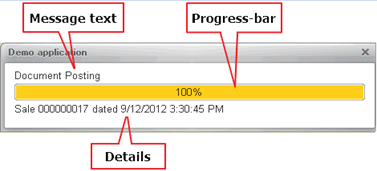
Fig. 193. Status display window
If you need to display the process execution progress by using a progress bar indicator (for example, we know the total number of employees and want to display how many of them have already been processed during payroll calculation), specify the second method parameter that sets an absolute value of the progress indicator when calling the State() method. The minimum progress indicator value is always set to 0. The maximum value is 100.
State ("Document
posting in progress (" + PeriodPresentation(StartDate, EndDate) + ")", ForProgress, "Documents are being posted for" + ProcessingDate + ". Total: "+ Counter, PictureLib.Post);If the second parameter is not specified when the method is called, the progress indicator will not be displayed on the status bar. In this case, the explanation text will be placed directly below the main description text:
State("Posted, , "Total documents processed: " + ProcessedDocumentsCount + Chars.LF + "Documents posted:
" + PostedDocumentsCount, PictureLib.Post);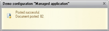
Fig. 194. Status without the progress bar
The status panel automatically disappears from the screen shortly after the program routine that opened the status panel is completed. However, if you hover the mouse pointer over the status panel window, it will be displayed until you manually close it or remove the pointer from the status bar area.
Note. Note. The status bar is located at the top of all windows of the current application, except for modal windows. A modal window is displayed on top of the status bar.
In web client, the status bar is implemented as a separate web browser window. The way it is refreshed depends on the web browser:
-
Microsoft Internet Explorer. The status is refreshed each time the State() method is called.
-
Mozilla Firefox. The status is refreshed after each server call and after the code in 1C:Enterprise language is executed. Therefore, in the absence of server method calls during code execution in 1C:Enterprise language, the status bar will not be refreshed.
-
Google Chrome and Safari. The status is refreshed only after the code in 1C:Enterprise language is executed.
6.3.4. Viewing messages
In the application, most messages are logically related to data. For instance, if there is a shortage of certain goods in the warehouse while the document is being posted, the developer must notify the user about it.
The message tool allows the developer to create an error message where the object attribute that caused the error can be specified. When displayed in a client application, a message can be automatically bound to a form item that edits this attribute, and the specified message will be displayed next to it.
Messages are displayed on the message panel located at the bottom of the work area. The message panel height does not exceed 5 lines. If the panel contains more messages, a scroll bar appears, but the panel height is not increased. The message panel height cannot be changed manually either.
To ensure that this tool is functional in the platform, use the UserMessage object.
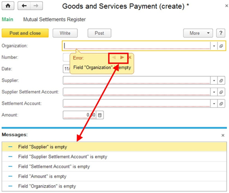
Fig. 195. Messages
The message tool informs the user that the requested action has failed. For example, document posting is impossible due to lack of certain goods in a warehouse.
If a message is attached to a table field, reordering of table rows does not affect the correct way of displaying the message.
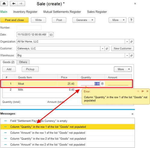
Fig. 196. Messages in a table
If a row to which a message is attached has been deleted, the message will be reattached to the form item (see Tables) that displays the table.
If a message is attached to a table row associated with a form attribute of the FormDataCollection, FormDataTree, or FormDataStructureAndCollection type, the user has interactively performed a search in this table (by using an appropriate standard command), and the row, for which the message is created, is hidden, the search will be automatically canceled and the message will be displayed in correct place. If a program filter is set for the table (the RowFilter property), such filtering is not canceled when the message is displayed and the message is positioned on top of the table as a whole.
It is recommended that you use messages generated by the global context Message() method or the UserMessage object only to inform users about erroneous actions. It is also recommended that you disable the closing function for the form in which messages are displayed if messages are generated during the execution of an action that implies closing the form. If the form closing function is not disabled, messages might be displayed in the message panel of the form being closed. In this case, the panel will be closed along with this form. If this happens, the user will not see the displayed messages. If you need to inform a user about an event, it is recommended that you use the ShowUserNotification() method (see User Notifications).
To attach an error message to a form item, the system must contain information on the attribute, the infobase object it belongs to, and the form item that displays it. Filling the properties listed above allows you to answer all these questions:
-
By defining the value of the DataPath property, you indicate which of the form attributes stores data of the required infobase object.
-
By setting the Field property, you specify the object attribute for which the message will be displayed. It can be said that a message will unfold the DataPath.Field data identified in the database by the DataKey value. Next, the system will automatically (based on the form structure data) determine the form item in which the required information is displayed. Finally, the message attached to this form item will be displayed.
The Field property can contain data description in the following format:
-
For attributes, a string formatted as AttributeName. For example, Vendor or Vendor.Parent.
-
For table attributes, a string formatted as TabularSectionName[RowIndex].AttributeName. For example, Products[10].Count.
-
For the record set rows, a string formatted as [RowIndex].AttributeName. For example, [10].Currency.
-
Remember that if a field to which a message is attached is moved by the user from a table to a form (for tables and record sets), the message will no longer remain attached to this field.
-
The TargetID property describes the form the message must be attached to. For example, if a message is generated from a form displayed on the home page, specifying the TargetID property will allow displaying the message attached to the form where the message was generated.
If the DataKey property is filled in the message and it does not match the key value of the current form's main attribute (an object reference or information register record key), a new object form corresponding to the DataKey property value is opened.
- If the DataPath property of a message is empty, the name of the main attribute of the open object form is assigned to it and the message is displayed in the newly opened form.
Besides, all messages with the DataKey property equal to the value of this property in the current message are transferred from the current form window to the open form. At the same time, if the DataPath property is not set, it is assigned for all transferred messages in a similar way.
To fill the data path, the system uses a special system tool. It saves mapping information on form items and objects and uses it when the SetData() method is called. This way, before executing the object module procedures where messages are created, form attributes and objects must be mapped and the developer must call the SetData() method in the module.
When performing standard actions with an object in a form, for example, when posting a document, the form extension automatically creates an object and maps it. Therefore, in these cases, the developer does not have to do anything.
Note. Note. If messages are generated to the user in a transaction when saving a new object (exchange plan, catalog, document, chart of accounts item, chart of calculation types item, chart of characteristic types item, business process, or task), once the transaction is canceled, the links to this object are cleared in the messages (DataKey property).
The mapping process of an object programmatically created from the form data is described below.
The relation between an object and a form can be specified explicitly, by calling a method, or implicitly. For explicit mapping, use the SetObjectAndFormConformity() method. As the second parameter, the method obtains data on the form where the object is displayed (the FormIdentifier property) and the attribute of the specified form where the data object is stored (the Attribute property). That ensures further correct mapping of messages and form controls:
Parameters = New Structure;
Parameters.Insert
("FormIdentifier", UUID);
Parameters.Insert
("Attribute", "Object");
SetObjectAndFormConformity(Object, Parameters);The mapping will exist as long as the mapped object exists.
For the message to use the mapping data of the object and attribute name, attach the message to the data using the SetData() method of the UserMessage object.
ObjectCatalog = RefCatalog.GetObject();
Parameters = New Structure;
Parameters.Insert
("FormIdentifier", FormIdentifier);
Parameters.Insert
("Attribute", "Object");
SetObjectAndFormConformity(ObjectCatalog, Parameters);
ObjectCatalog.CheckFilling();Consider that in the SetObjectAndFormConformity() method, the attribute name is specified for the form that will be opened by default to display the item of the catalog in use (ObjectCatalog in our example). In this case, the messages created in the filling check handler (ObjectCatalog.CheckFilling()) will be correctly attached to the attributes of the new form. If the FormID property of the Parameters structure (in the example above) contains a unique ID that does not match any form instance, a new form will be created and opened to display the message.
To get a mapping, you can use the GetObjectAndFormConformity() method. You can get it as long as its object exists.
MapDescription = GetObjectAndFormConformity(Object);If there is a map with an attribute for the passed object, the function will return the attribute name. Besides, mapping can be established via the form by using the FormAttributeToValue() method. This method is recommended in most cases.
// Code in the document
module. &AtServer
Procedure Posting()
... Message = New UserMessage();
Message.Text = "In row 10 of the Products table," + "the number of missing product item(s) is " + MissingItemsCount + " " + ProductsMeasurementUnit;
Message.Field = "Products[9].Count";
Message.SetData(ThisObject);
Message.Message();
// The message will be displayed in the form and attached to
// the control associated with the field
// Quantity in row 10
// of the Products table.
...
EndProcedure;If user messages (by using the UserMessage object) are created during a context or non-context server call from a form or during a call from a common module or from a common command module, the output of messages is locked. Created messages will be displayed to the user after returning control to the client. To get a list of not displayed messages, use the GetUserMessages() method.
If there is an invalid value in the input field to which the message is attached, you can switch to the message window in the web client. In other client applications, such transition is impossible.
6.3.5. Keyboard shortcuts
In an independent auxiliary window, the following keyboard shortcuts are functional:
-
For commands of the main window navigation panel
-
For commands of the main window actions panel
-
For auxiliary window commands (both form commands and navigation panel commands).
At the same time, keyboard shortcuts for main window commands have effect even if the command called by any keyboard shortcut is invisible, for example, hidden by the user. In auxiliary windows, keyboard shortcuts have no effect for hidden form navigation bar commands or hidden form items.
In blocking windows, only window keyboard shortcuts are functional. Keyboard shortcuts for main window commands are not supported.
6.3.6. Form list operations
The system allows you to get a list of forms that are currently displayed in the system, including forms located on the home page (desktop). To get this list, use the GetWindows() global context function. After that, analyze the contents of the resulting ClientApplicationWindows collection that consists of objects of the ClientApplicationWindow type:
-
The window whose Main property is set describes the main application window. The Content property for such window always contains an empty array.
-
The window whose HomePage property is set describes the home page (desktop). The Content property contains a list of forms that are currently located on the home page (desktop).
-
The remaining windows describe auxiliary windows of the client application. The Content property for such window contains a list of forms opened in this window. The main form of such window will be the first array element.
Remember that the order of elements in the ClientApplicationWindows collection is not defined. In applications, it is not recommended that you rely upon any assumptions regarding the order of elements in this collection.
The following example displays all windows of the client application, outputs their properties and the list of forms that are located in a certain window of the client application (if any).
An example of displaying the windows list:
Windows = GetWindows();
For Each Window In
Windows Do
Message("Title:
" + Window.Title);
Message("Main
application window: " + Window.Main);
Message("Home
page: " + Window.HomePage);
Message("Number
of forms in the window: " + Window.Content.Count());
If Window.Content.Count() Then
For Each Form
In Window.Content Do
Message(" Form : " + Form.FormName);
EndDo;
EndIf;
Message("-----");
EndDo6.3.7. Using the jump list
Microsoft Windows 7 or later (OS version 6.1 or later) and Linux with the Unity desktop shell allow users to use so-called jump lists. This feature allows the user to quickly navigate to objects of the program being used (files, folders, and so on) by right-clicking the command panel associated with this application.
You can pin some objects to this menu using a special button. In fig. 197, you can see an example of the jump list for Windows Explorer on Windows 7.
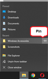
Fig. 197. Jump list in the taskbar
You can find more details on the jump list in manuals to respective operating systems.
1C:Enterprise also provides a jump list. Infobase acts as an object in this list. The jump list is synchronized with the list of recently selected infobases of the launcher window, even if this list is hidden in the launcher.
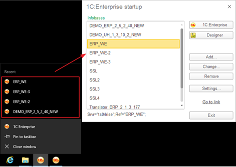
Fig. 198. The 1C:Enterprise jump list
When using jump lists, keep in mind the following system behavior specifics:
-
Infobases from the jump list are always started in 1C:Enterprise mode.
-
To display the jump list, dock it by using the Dock to the Taskbar command for the 1C Enterprise desktop shortcut created by the 1C:Enterprise installer.
6.3.8. Installing preview window buttons for the Windows taskbar
For Microsoft Windows 7 and later OS versions, Aero Peak function is available to users. This function allows you to preview the thumbnails of all windows associated with the selected program by hovering the mouse pointer over respective taskbar button. Some programs place special buttons in these thumbnails, which facilitates program management. For example, Windows Media Player places buttons for navigating between tracks and stopping/starting playback in the preview window.
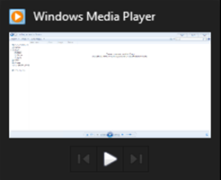
Fig. 199. Windows Media Player screenshot
1C:Enterprise provides an option to place similar buttons in thumbnails of running infobases. To do this, use the special global context OSTaskbar property. Let us look at the way this property can be used.
As an example, we will add two buttons to the preview window:
-
Place customer order
-
Register new sale
We will create buttons at the beginning of the system startup:
Procedure BeforeStart(Cancel)
Buttons = New Array();
Button1 = New Structure();
Button1.Insert("Image", PictureLib.CustomerOrder);
Button1.Insert("Title", "Place customer
order");
Notification = New NotifyDescription("ButtonsActions", ButtonsNotifications, "RegisterNewOrder");
Button1.Insert("Action", Notification);
Button2 = New Structure();
Button2.Insert("Image", PictureLib.NewSale);
Button2.Insert("Title", "Register new sale");
Notification = New NotifyDescription("ButtonsActions", ButtonsNotifications, "Register new sale");
Button2.Insert("Action", Notification);
Buttons.Add(Button1);
Buttons.Add(Button2);
OSTaskbar.SetButtons(Buttons);
EndProcedureWhen you click any of the created buttons, it will trigger the handler that will perform the required action. However, a managed application module cannot contain notification handlers. Therefore, we need to create (or use) a client common module that will host the handler. In the example, we specified the ButtonsNotifications common module and the ButtonsActions() handler.
Procedure ButtonsActions(AdditionalParameters) Export
If AdditionalParameters = "PlaceOrder" Then
// an order document is created here
ElsIf AdditionalParameters = "CheckoutSale" Then
// a sale document is created here
EndIf;
EndProcedureAs a result, the preview window for the running infobase with the above changes will look as follows:
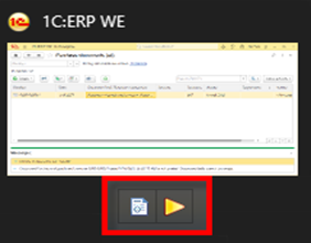
Fig. 200. Buttons in the taskbar preview window
Now, to place an order and checkout a sale, you do not need to expand the main application window and search for the required commands in the command interface.
When using this tool, consider the following features and limitations:
-
The maximum number of buttons in the preview window is 7.
-
You cannot increase the number of buttons in the preview window after the first creation. You can change and hide previously created buttons.
-
Any button picture is allowed, but we recommend that you use the .ico format that contains pictures of 16x16, 20x20, and 24x24 sizes (for 96, 120, and 144 DPI respectively).
-
All three properties are required in the structure that describes each button. Properties cannot be omitted.
On Linux, buttons created in the preview window do not have any effect.
6.3.9. Taskbar overlay icon management
When 1C:Enterprise is running, something that requires the user's attention might happen in the system. For example, the built-in mail system has received another email batch and the counter of unread letters has increased or some long-running action has been completed.
If the system is running on Windows 7 (or later versions), the application developer can implement the following options:
-
Set an overlay to the infobase icon displayed on the command bar. You can use a picture or a number as an overlay icon.
-
Make the command bar button associated with the infobase flash.
Let us consider some examples in detail.
Placing an overlay icon in the taskbar button
Imagine that there is a special task exchange service in the information system. You need to display the number of currently available tasks in the system to the user. To implement this, let us use an idle handler (timer) that will check how many tasks are assigned to the user every 60 seconds (for example) and display this number to the button representing the infobase on the command bar.
Procedure BeforeStart(Cancel)
AttachIdleHandler("WaitingProcedure", 60, False);
EndProcedure
Procedure WaitingProcedure() Export
Counter = Messages.GetTasksCount();
If Counter = 0 Then
OSTaskbar.RemoveBadge();
Else
OSTaskbar.SetBadge(Counter, False);
EndIf;
EndProcedureIf there are no tasks assigned to the user, the previously set overlay number will be removed from the icon. If the second parameter of the SetBadge() method is set to True, the system will delete the overlay when the corresponding application is selected.
Taskbar button flashing
Displaying an overlay icon to the taskbar buttons is a good practice when an application processes some countable information. In this case, the display of a plain number could be sufficient. However, if the system completes a long-running process, it cannot be indicated by placing an overlay icon in the taskbar button. Nonetheless, it is possible to signal this change (the end of process) by flashing the taskbar button.
To control such alert signals, use the OSTaskbar.Flash() method. The system behavior upon calling this method depends on the operating system in use.
Let us review an example in which we will set the timer to 120 seconds to simulate a long-running process. At the end of this time span, the taskbar button will flash 5 times.
Procedure BeforeStart(Cancel)
AttachIdleHandler("WaitingProcedure", 120, True);
EndProcedure
Procedure WaitingProcedure() Export
OSTaskbar.Flash(5)
EndProcedure120 seconds after the client application startup, the taskbar button associated with the application will flash 5 times in a row.
Icons on the Windows taskbar buttons are displayed only when the "Use small icons" checkbox in the taskbar settings is cleared. On Unity user interface in Ubuntu, there might be no visual effects if 1C:Enterprise is running with superuser rights (root).
6.4. Command interface development order
When developing a command interface, the following sequence of actions is usually performed:
-
At the beginning of configuration development, developers define its structure in terms of its subject domain and create a tree of configuration subsystems.
-
After that, they create roles and define potential configuration users.
-
When developers create new configuration objects (catalogs, documents, and so on), they usually immediately assign the objects to certain subsystems and assign access rights to the objects by roles.
-
If the standard arrangement of commands and their default visibility appear unsatisfactory, developers edit the Command interface property of the subsystems in question as well as commands of those forms in which the parameterized commands for required objects are automatically placed (navigation to the subordinate list and object generation).
These basic actions will place commands for opening object list forms and commands for generating new objects in the respective command interface sections (if their visibility in the command interface section editor is enabled). Besides, if it is defined so in the object properties, the forms of other configuration objects will filled with generation commands, commands for navigation to lists by recorder, commands for navigation to list by owner, and so on.
Let us consider an example of creating the Goods consumption document. When creating it, we will do the following:
-
Indicate that the document belongs to the Sales records and Accounting subsystems
-
Assign access rights for this document to the Sales manager and Administrator roles
-
Indicate that the document is generated based on the Account and Customer order documents
-
Indicate that it is the recorder for the Warehouse inventory register
These actions will make the Goods consumption command appear in the navigation panel of the Sales records section if the user has the Sales manager role or administrative rights.
Besides, the Generate submenu command for generating sales invoices will appear in the forms of the Account and Customer order documents. We did not have to edit the interfaces for users with such roles and the forms of the Account and Customer's Order documents.
The standard presentation of the "Navigate to invoice list" command (Goods consumption) might look inaccurate. To redefine it, fill the List presentation property of the GoodsConsumption document and specify Sales there.
Imagine that we are not satisfied with the default object presentation involved in the command presentation and we want to change it so that the generation command presentation is as follows: Sale: generate. To do this, fill the Presentation property of the Goods consumption document object with the Sale value.
Consider that with the standard command positioning, it is located in the middle of the command list in the Sales records section. Suppose the command is important enough for this section. We navigate to the All subsystems editor (or to the command interface editor of the Sales records subsystem) and move the command to the Important group. Meanwhile, we leave the Accounting section as it is without changing the default command placement.
Finally, we need to pay attention to the default visibility of commands. In the form of the Goods consumption document, a command for navigation to the record list of the Warehouse inventory register has appeared. However, it is invisible by default. Let us assume that this command is important for the system administrator, but is not really relevant for the manager. To reflect this, we will create a form for the Goods consumption document, proceed to editing the command interface, and enable the visibility of the command for navigation to the register list for the Administrator role without changing its visibility for the manager.
For the system administrator with their broad access rights, the number of commands appeared too large. Suppose that they will rarely use the command for navigation to the sales invoice list. To make their command interface more user-friendly, we once again go to the All subsystems editor and disable the command visibility for the Administrator role.
You can also set the default visibility for the command for adding the Goods consumption document in the actions panel for the sales manager. This way, they can trigger generation of this document without going to the document list.
When using the configuration, the user can set up visibility of commands according to their preferences.
Chapter 7. Forms
7.1. General information
A form is an object created to input and view information, as well as to manage various processes. The application uses forms to ask the user for the required information, or to display data for the user to view and edit.
The main purpose of the form is to provide a user with a convenient means for entering and viewing information. Like a paper document, the form allows you to quickly enter the required information and save it for further processing, and if necessary, go back to the previously input data for viewing or correction.
The displayed part of the form (visible to users) is described as a tree that contains form items. Form items can be input fields, checkboxes, radio buttons, regular buttons, and so on. Besides, an item can be a group that contains other items. A group can be represented as a framed panel, a panel with pages (tabs), a page itself, or a command bar. Moreover, an item can be a table that also contains items (columns). The item structure describes how the form will look like. Whereas all the functions of a form are described by dint of properties and commands. Properties are the data that a form operates on, and commands are the actions it performs. Thus, a developer, by using the form editor, should include the desired properties and commands in the form, create the controls that display them and, if necessary, arrange the controls into groups.
The system can automatically create the form of an applied object, but developers are able to create a form themselves and to determine the composition of its properties, commands, and displayed controls. Drawing on this logical description, the system automatically shapes an appearance of a form, to display it for users. That said, the system takes into account various properties of the displayed data (for example, their type), in order to arrange the form controls as user-friendly as possible. The developer can fine-tune the item placement with various settings. They are able to define the order of controls, set their desired width and height. However, this is just some extra information that helps the system display a form.
In forms, a developer can use not only the commands of the form itself, but also the global commands used in the command interface of the entire configuration. Besides, an option to create configurable commands that will open other forms based on the specific data of the current form is implemented. For example, it may be a call of a stock balance report for a particular warehouse that is at the moment selected in the sales invoice form.
There is a feature in forms for attaching user messages to the form data. This allows the system to visually mark and activate form controls in which the user made a mistake when filling them in.
Also, the form automatically considers the role availability of data. For example, if a particular attribute of the displayed object is not available for viewing to a specific user, the system will automatically remove the form control associated with this attribute and then rebuild the form.
To create the form, use the form editor available in the Designer mode (see Form editor). In this editor, the following features can be defined:
-
Form attributes. Intended for storing data that the form works with (see Form attributes).
-
Form parameters. Intended for arranging relations between the forms and controlling the functionality of the form when opening it (see Form parameters).
-
Form commands. Intended for performing various actions within a form (see Form commands).
-
Form module. Contains the program code associated with the form functioning (see Form module).
-
Form items. Intended for displaying and editing form attributes, as well as displaying and running commands (see Form items).
Command interface. Contains commands that can be executed in a form and are provided by both the global command interface and the form commands.
Note. IMPORTANT. Forms are present both on the server and the client at once. Always keep this in mind when designing a form.
7.2. Form attributes
7.2.1. General information
A set of form attributes describes the data that is displayed, edited, and stored in a form. All the same, the form attributes themselves do not provide options to display and edit data. Rather, the form controls associated with the corresponding form attributes are intended for displaying and editing the data. The set of all form attributes will be called form data.
Note. IMPORTANT. Keep in mind that all form data must be described as form attributes. It is not allowed to use the form module variables as data sources for the form controls.
During form development, you can explicitly set an option to view and edit specific form attributes, broken down by roles, using the View and Edit properties (for details, see Role-based form customization). Besides, you can configure the availability of a certain attribute in a form using functional options (for more information on functional options, see Functional options and functional option parameters).
There is an option to assign the Main attribute of the form, which is an attribute that defines the standard form functionality (form extension).
Note. IMPORTANT. Keep in mind that a form can have only one main attribute.
The form extension comprises additional properties, methods, and form parameters of the ClientApplicationForm object that are specific to the main form attribute type.
7.2.2. Form data types
The form operates with a limited set of data types:
-
Types that are directly used in a form. They are types that are supported on both the thin client and web client (for example, Number, CatalogRef.Goods, GraphicalSchema, and SpreadsheetDocument).
-
Types to be converted to special data types. They are form data types. Such types are displayed in the list of form attributes in parentheses, for example, (CatalogObject.Items).
-
Dynamic list is a special data type that allows you to organize the display of arbitrary information retrieved from database tables in the form. To do this, specify the displayed table or describe the resulting selection in the query language. The tool is based on the data composition system and provides a set of options for sorting, selecting, searching, grouping, and conditional appearance of the received data.
Some applied types (such as CatalogObject and so on) are not present on either the thin client or the web client. Therefore, for presentation of such applied types in the form, the platform has some special data types designed to work in forms. This features makes it necessary to convert applied objects into form data (and vice versa).
The following data types are used:
-
FormDataStructure. Contains a set of properties of arbitrary type. Properties can be other structures, collections, or structures with collections. For example, this type represents the CatalogObject in the form.
-
FormDataCollection. Array-like list of typed values. A collection element is accessed by index or ID. In collections derived from registry record sets or tables of objects, the LineNumber field of the collection element does not correspond to the actual index of the collection element. In some cases, there may be no access by ID, owing to the type of an applied object that is represented by this collection. Any integer can act as an ID. This type represents a table in the form.
-
FormDataStructureAndCollection. Object that is represented as a structure and a collection at once. It can be handled like either of these entities. For example, this type represents a record set in the form.
-
FormDataTree. Object intended for storing hierarchical data.
Note. Important. It is not recommended that you use form data as parameters of procedures and functions that transfer control from the client to the server, and also as function return values if control is transferred to the client.
Note. Important. When calling server procedures and functions and returning control to the client, only changes to the form data are transferred. When the Arbitrary type is selected as the form attribute type and the mutable value is selected as the attribute value, then in order to transfer the data between the client and the server (and back) correctly, it is necessary to assign it again to the form attribute after the mutable value is changed.
An applied object is represented by either one or several form data items. On the whole, the hierarchy and composition of the form data depend on the complexity and interrelation of the applied objects of the form.
For example, a document containing a table will be represented by an object of the FormDataStructure type (document) to which the object of the FormDataCollection type (document table) is subordinate.
Note. IMPORTANT. When you design a configuration, keep in mind that applied objects are only available on the server, while form data objects can be used on both the server and the client.
When you form the form attributes, consider a number of restrictions:
-
Form data can store only those types of 1C:Enterprise for which XDTO serialization is specified (see Specific features of using objects, their properties and methods).
-
It is forbidden to assign values of the Array and Map types to the form attributes.
-
For the attributes of the arbitrary type of the objects, such as FormDataStructure, FormDataCollectionItem, FormDataTreeItem, FormDataStructureAndCollection, the assignment of values of the Array and Map types is not allowed.
-
It is not recommended that use values of the Array and Map types as elements of collections of the Structure or ValueList type. In the above cases, use fixed collections: FixedArray and FixedMap.
-
It is not recommended that you use the Structure and ValueList types in form attribute data (that is, in attributes of attributes).
-
If a form attribute is of the Arbitrary type, or if a collection (array, map, and so on) is used as a value of such attribute, then do not set such attributes (or collection properties) to values that contain the following applied objects:
-
DocumentObject
-
CatalogObject
-
BusinessProcessObject
-
TaskObject
-
ChartOfCharacteristicTypesObject
-
ChartOfCalculationTypesObject
-
ExchangePlanObject
-
ChartOfAccountsObject
-
ExternalDataSourceCubeDimensionTableObject
-
ExternalDataSourceTableObject
-
In fact, we can say that form data is a unified presentation of data from various applied objects on which the form operates in a uniform manner, and which are present both on the server and on the client. That is, a form contains a certain projection of these applied objects in the form of its own data types and performs conversion between them if necessary. However, if a configuration developer implements their own data processing algorithm, then they must perform the data conversion (from specific types to applied types and back) independently.
When editing form attributes, you can influence the data transfer between the server and the client while the form is running. To do this, use the Always use attribute editor column. The action of this property differs for the three types of attributes:
-
For an attribute subordinate to a dynamic list (dynamic list column):
-
The property is enabled. An attribute is always read from the database and included in the form data.
-
The property is disabled. An attribute is read from the database and is included in the form data only when there is a currently visible form item associated with the attribute or its subordinate attribute.
-
-
For an attribute subordinate to a register record collection:
-
The property is enabled. Document register records are read from the database and will be present in the form data.
-
The property is disabled. Document register records will not be read from the database and will not be included in the form data (if there is no form item that refers to document register records).
-
-
For the rest of form attributes:
-
The property is enabled. An attribute will be present in the form data, regardless of whether there is at least one form item associated with the attribute or its subordinate attribute.
-
The property is disabled. An attribute will be present in the form data only if there is a form item associated with the attribute or its subordinate attribute. Unlike dynamic list attributes, the visibility of the item associated with the attribute does not matter in this case.
-
Note. Note 1. Keep in mind that a property set for the parent attribute affects all its subordinate attributes. For example, if the Always use property is cleared for the document table, then the system assumes that this property is cleared for all its subordinate attributes as well (despite the actual state of the property).
Note. Note 2. For form attributes of an object type (CatalogObject, DocumentObject, and so on), the Ref, DeletionMark, and IsFolder attributes are always present in the form data (if the object has the corresponding attribute), regardless of the Always use property state.
Note. Note 3. It is not allowed to assign values of other form data objects to the form data attributes.
If in the attribute editor (the Type column), the type description is displayed in parentheses, for example (CatalogObject.Items), this means that the applied type will be converted to the form data types.
If the form data contains an invalid type (such as an attribute of a form attribute), then a warning will be displayed in the form attribute editor, next to the name of the attribute type, "Not available in form data". In 1C:Enterprise mode, the form field corresponding to this attribute will not be generated. No errors will be output. When copying and editing objects containing such data, you should independently implement the program code that provides copying and working with such attributes within the form.
Next, let's take a look at some features of the form attributes belonging to various types:
-
For form attributes of the ValueTable and ValueTree types, you can add columns (the Add attribute column command). This defines the data structure of the collection being created.
-
For attributes of the FormDataCollection type (for example, object tables) and the FormDataStructureAndCollection type (for example, sets of register records), you can specify additional attribute columns (the Add attribute column command) that have no association with the data stored in the infobase.
The system will create these columns as the form data is being generated. You can access such attributes both on the client and on the server.
Example of filling in an attribute column not associated with the form data:
&AtServer
Procedure OnReadAtServer(CurrentObject)
For Each Row In Object.Goods Do
// TypeOfItem is an attribute not associated with the data
Row.TypeOfItem = Row.Product.Type;
EndDo
EndProcedure- For an attribute of the ValueList type, you can set the value type (the Value type property) that will store the list. At the same time, the system will automatically limit the type of data to be added when adding interactively. Also, programmatic addition is not prohibited, yet an attempt will be made to cast the value of the type being added to the limiting type (or union type). You can also associate the Value type property with a form item and interactively limit the data types that can be added to the value list.
For an attribute of the DynamicList type, you can set up list parameters: main table, settings, and so on.
Note. IMPORTANT. Attribute columns that are not associated with the data do not participate in the conversion of values between the form data and the infobase objects, and vice versa.
For a description of the View and Edit properties, see Role-based form customization.
Form data modifications are displayed by the form items as soon as the execution of 1C:Enterprise language is completed or following a forced call of the RefreshDataRepresentation() method. Consider an example.
Let's say there is a Counter attribute of the Number type in the form. This attribute is displayed on the form by a field of the Indicator field type. Let there be some action whose progress should be displayed by the indicator. To call the action, click a button on the form:
Procedure FormCommandHandler()
For Counter=1 to 100 Do
ExecuteAction();
EndDo
EndProcedureIf you click the button that initiates this command in 1C:Enterprise mode, the indicator will first be in the leftmost position, and then immediately in the rightmost one (we assume that the ExecuteAction() method runs for a while, which should allow you to see the indicator change). That is, the indicator will be refreshed only when the execution of the command handler is over.
In order for the indicator to display the progress of the operation, the handler code must be replaced with the following:
Procedure FormCommandHandler()
For Counter=1 to 100 Do
ExecuteAction();
RefreshDataRepresentation();
EndDo
EndProcedureAfter this modification, the indicator will start changing during the execution of the code placed in the command handler.
Note. Note. In the web client, calling the RefreshDataRepresentation() method will refresh the form items only after the execution of the code in 1C:Enterprise language.
7.2.3. Converting applied object data to form data and back
There is a set of global methods for converting applied object data to form data and back:
-
ValueToFormData()
-
FormDataToValue()
-
CopyFormData()
Methods that work with applied objects are available only in the server procedures. The method for copying values between form data is available both on the server and the client, since it does not require applied objects as parameters.
When converting form data to an applied object, consider their compatibility.
-
ValueToFormData(). Converts an applied object to form data.
-
FormDataToValue(). Converts form data to an applied object.
-
CopyFormData(). Copies form data with a compatible structure. Returns True if the copy is successful. Returns False if the object structure is incompatible.
When converting form data to applied objects and back, objects are cached and the cached object version is checked for relevance.
Note. Note. When executing standard actions (opening a form, running a standard Write command, and so on) in a form with the main attribute, the conversion is performed automatically.
Let's take an example of how to use data conversion in native algorithms.
&AtServer
Procedure OnCreateAtServer(Cancel, StandardProcessing)
ObjectItem = Goods.FindByDescription("CoffeePot").GetObject();
ValueToFormData(ObjectItem, Object);
EndProcedure
&AtClient
Procedure Write()
WriteAtServer();
EndProcedure
&AtServer
Procedure WriteOnBackEnd()
ObjectItem = FormDataToValue(Object, Type("CatalogObject.Goods"));
ObjectItem.Write();
EndProcedureAlso, the ClientApplicationForm object has methods available on the server
-
ValueToFormAttribute(). Converts an applied object to the specified form attribute.
-
FormAttributeToValue(). Converts a form data attribute to an applied object.
Using these methods is usually more convenient since they contain, for example, information about the form attribute type. Besides, the FormAttributeToValue() method sets the mapping between the form data and the object that is used when generating messages (see Viewing messages).
When converting objects of the ValueTable or ValueTree type to form data using either the ValueToFormData() or ValueToFormAttribute() method, note that the object to be converted must contain all form data columns.
Note. IMPORTANT. Attribute columns that are not associated with the data (see Form data types) do not participate in the conversion of values between the form data and the infobase objects, and vice versa. Columns that are missing in the object data are cleared when converting to the form data.
Note. When an object is transferred to the form data by the platform, or by calling the ValueToFormData() and ValueToFormAttribute() methods, only the object data is transferred. The internal object state is not transferred to the form data. For example, the new object reference value that is set to an object by the SetNewObjectRef() method will be lost when converting the object to the form data and back.
Only form attributes of the following types can be used as the first parameter of the FormAttributeToValue() and FormDataToValue() methods: FormDataStructure, FormDataCollection, FormDataStructureAndCollection, and FormDataTree. Below is an example of using these methods.
&AtServer
Procedure RecomputeAtServer()
// Convert the Object attribute to an applied object.
Document = FormAttributeToValue("Object");
// Perform recomputing by the method defined in the document
module. Document.Recompute();
// Convert the applied object back to an attribute.
ValueToFormAttribute("Document", "Object");
EndProcedure7.2.4. Attribute properties
This section contains a description of some properties of the form attributes.
Title is a text that is used as the title of the form item associated with this attribute if the Title property of the form item is not specified explicitly.
Main attribute determines that the given form attribute is the main one and thus determines the form extension.
Stored data. If this property is set to an attribute, then interactive modification of such attribute will result in:
-
Attempt to block the associated form attribute.
-
Selecting the Modified checkbox in the form.
-
If the attribute has the Stored data property enabled and the form is in the View only mode, then all form items associated with this attribute will also be in the View only state.
Fill check. Determines whether it is necessary to check this attribute for filling (the property value is Display error). The Fill check is available only for the attributes of the following types:
-
Primitive data types (Number, String, Boolean, Date, any types of references, standard period)
-
Value list
-
Value tree
-
Value table
Note. Note. Attribute filling is checked similar to the ValueIsFilled() function. The table filling check implies that a table is considered to be filled when it contains at least one row.
7.3. Special types of form attributes
7.3.1. Dynamic list
7.3.1.1. General information
A dynamic list is a special data type that allows you to display arbitrary information from database tables on a form. To do this, specify a table you want to display the data from, or describe the resulting selection in the query language.
The tool is based on the data composition system (see Data composition system) and provides a set of options for sorting, selecting, searching, grouping, and conditional appearance of the received data. In this case, the source of data is a query that is either generated automatically by the system (based on the specified data) or written by the developer manually.
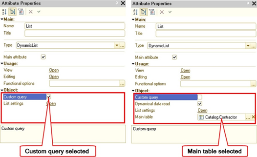
Fig. 201. Options for generating a dynamic list
When creating a form attribute of the DynamicList type, the developer can choose either of two ways to generate a data query:
-
By specifying the main table. In this case, specify the table (the Main table property) you need to receive data from, and the system will automatically generate a data query (see the right side in fig. 201).
-
By manual query input. In this case, set the Arbitrary query property (see the left side in fig. 201). After that, manual query input for receiving data from the infobase will become available.
With a query, you can select data from multiple tables, so you can specify the main table. This is necessary so that the dynamic list can determine which data is primary and which is secondary, and can correctly select and display information, as well as provide standard commands. However, if it is not possible to determine the main table in a query, then it may be left unspecified, but then the dynamic list will not provide the commands associated with the main table. Besides, in this case (without specifying the main table), the efficiency of retrieving data with a dynamic list will be significantly reduced.
To improve performance, it is recommended that you make all joins used in an arbitrary query only for retrieving additional data optional using the extension of the query language of the data composition system (see Query language extension for the data composition system).
For a dynamic list, which is the main form attribute, you can set filter values by using the Filter form parameter. For this, the name of the structure property, which is in the Filter parameter, must match the name of the dynamic list filter field. In this case, the value of the structure property will be set as the right-side value of the filter item. If an array, a fixed array, or a value list is passed as the Filter parameter item value of the dynamic list form, a condition with the In list option is added to the selection, in the right-side value of which the value list is placed (into which an array and a fixed array are converted).
An arbitrary query in a dynamic list can be a query in which a parameter is used to generate the value of a field, for example:
SELECT
CASE
WHEN Delivery.Index = 1 THEN &Presentation
ELSE Delivery.Index
END AS Index
FROM
Document.ProductDelivery AS DeliveryAt the same time, if the parameter value type differs from the object attribute type (for example, Attribute1 is of the Number type, and the parameter value is of the String type), then to display the field correctly, explicitly cast the parameter value to the required type:
SELECT
CASE
WHEN Delivery.Index = 1 THEN CAST(&Presentation AS Row(100))
ELSE Delivery.Index
END AS Index
FROM
Document.ProductDelivery AS DeliveryIf a field by which the filter is set is disabled using functional options, then the filter by this field is not set even if the filter value is passed as form parameters or selection parameter links.
Use the Read data dynamically property to instruct a dynamic list to read data in small portions (for more information on methods for obtaining data using a dynamic list and caching data, see Methods for getting and caching data with a dynamic list). Regardless of this feature, the following conditions apply:
-
If the view mode is set as a hierarchical list, only the data of the current group and the data of all parent items (without their child items) will be read.
-
If the tree view mode is set, only the data of open tree nodes will be read.
-
One-time loading of dynamic list data is not supported if the hierarchical view is selected (theDisplay property is set to Tree) and the initial tree view is set to Expand all levels. To get data, as many requests to the server will be made as there are nodes in the displayed list.
The Get invisible field presentations property controls how to get presentations for the list fields that are not displayed on the form or are associated with actually invisible form items:
-
The property is set to True. For thin client and web client, the dynamic list receives presentations for all fields of the reference type that are passed to the client.
-
The property is set to False. For thin client and web client, the dynamic list receives presentations only for those fields of the reference type that are displayed with actually visible form items. If the managed form table is in the selection mode, then the presentation for the key fields is received anyway.
Note. Tip. For a dynamic list with many reference fields that are not associated with table columns or form items, but have the Always use checkbox selected, setting the value of the Get invisible field presentations property to False can result in faster data retrieval with a dynamic list. However, if the values from such fields somehow get into the form items or participate in the generation of text strings, do not set the Get invisible field presentations property to False, as this will lead to additional server calls to get the presentation.
Within a single data retrieval, a dynamic list reuses previously created temporary tables if the following conditions are met:
-
In the batch list query, there is no query following the main batch query.
-
Temporary tables and their fields have not changed since the previous execution of the batch query.
The dynamic list uses the values of the following properties of the metadata object attributes:
-
Format
-
Editing format
-
Tooltip
-
Negative value selection flag
-
Mask
-
Multiline mode flag
-
Extended editing flag
-
Password mode
When displaying and editing the filter and the data composition system parameters, the editing format of the corresponding field is used.
7.3.1.2. Restrictions and specific features
When setting a filter in a dynamic list, note that the filter does not affect groups if the dynamic list is set to the Hierarchical list or Tree display mode. The "groups" refer to catalog items or charts of characteristic types for which the IsFolder property is set to True.
Filters that are automatically applied by a dynamic list to standard attributes such as Owner, Parent, Date, Period, and IsFolder, are made by standard tools of the data composition system. Filters that are automatically applied by a dynamic list to key fields can be made either by standard tools of the data composition system or by directly adding the IN condition to the query text for the fields of the main table. As a result of applying filters by the composition tools, they can be applied both in nested queries and in virtual table parameters.
When developing dynamic lists, it is recommended that you check all dynamic lists with custom queries. Make sure that if there are nested queries or virtual tables in the list query, and there are fields available for filtering with aliases that match the aliases of the standard attribute such as Owner, Parent, Date, Period, IsFolder or key fields, then these fields actually match the standard attributes with which they have the same alias. If this is not so, change the query so that they match or the alias differ.
If manual query generation is selected, then some restrictions are imposed on the query:
-
The use of the FIRST instruction in a dynamic list query is not supported. If it is necessary to use a selection with a limited number of records in a dynamic list, rework the dynamic list generation query in such a way that the actual content of the query is placed in a subquery and limit the number of the records to be received in this subquery. Instead of a subquery, you can also use a temporary table.
-
Filtering, sorting, and grouping are not supported:
-
By table attributes.
-
Presentation fields.
-
DataVersion field.
-
PredefinedDataName field.
-
Field Type of the chart of accounts table.
-
Field RecordType of the accumulation register table.
-
Field ValueType of the chart of characteristic types table.
-
Field of the Type type.
-
Field of type String (of unlimited length).
-
Field of the BinaryData type.
-
-
Sorting and grouping by the ExtDimension<ExtDimensionNumber> and ExtDimensionType<ExtDimensionNumber> fields of the RecordsWithExtDimensions table of the accounting register are not supported.
-
Sorting by fields of the union type that includes more than 100 types is not supported. Such fields will be excluded from the list of available order fields.
-
Grouping by fields that are query language expressions containing aggregate functions is not supported.
-
With the main table selected, a dynamic list query has the following limitations:
-
Merge is not supported.
-
The ORDER BY section is not supported. Use a query without the main table or set the necessary ordering through the dynamic list settings.
-
-
If a dynamic list is displayed as a hierarchical list or a tree, then a record will not be displayed by the dynamic list if at least one parent of this record is not displayed. In other words, to display an item in a hierarchical list, a dynamic list must also display all parents of this item up to the top of the list. In this case, the top of the list means either the root item of the hierarchical object displayed by the dynamic list or an item set as the TopLevelParent property of the form table extension for the dynamic list.
You cannot use the following tables as the main table of a dynamic list:
-
A table with no key that uniquely identifies each table record (reference for object tables and record key for register tables). However, you can set the following tables as the main table of a dynamic list (despite the lack of the key):
-
The ExtDimention table of the accounting register.
-
All virtual tables of the accounting register, except for the RecordsWithExtDimensions table.
-
Tables containing constant values (including the Constants table).
-
Tables of external data sources with no key fields.
-
Cube dimension tables for external data sources.
-
Accumulation register tables:
-
Turnover table
-
Balance table
-
Turnover and balance table
-
-
Calculation register tables:
-
True effective period table
-
Schedule data table
-
Base data table
-
-
-
Tables of object tables.
-
Change registration tables (used in data exchange algorithms).
-
Tables of sequences.
-
Tables of recalculations (used in periodic calculation algorithms).
-
Tables used in a query only in an external connection.
In other words, a dynamic list with the specified main table will work correctly if the query specified as a data source does not increase the number of rows obtained from the main table (taking into account the imposed filter). If the query increases the number of rows received by the query from the main table, this will violate the uniqueness of the record key of the table displayed by the list. In this case, disable the use of the main table of the dynamic list.
When working with a dynamic list, consider the access rights to the attributes displayed in the list:
-
Dynamic list columns with the Always use property enabled for which the current user does not have the View right are not passed to the client. Access to the data of such columns (using the CurrentData property and the RowData() method) is not possible on the client.
-
If the current user does not have the View right to the key field of the dynamic list, obtaining this dynamic list results in an access violation error.
For a dynamic list that displays an enumeration, you cannot interactively customize the list.
The columns and the settings of the dynamic list are associated with the query fields by the aliases of the selection fields. If an alias is not explicitly specified in the query for the selection field and the field is a system field, then the field name in the English version of 1C:Enterprise language is used as the alias. The specified link means that if you change an alias (or explicitly specify an alias for a field that has an automatic alias) of the query field that generates dynamic list data, the dynamic list attribute settings will be lost, the form items will "lose" the attributes to display, the dynamic list settings will become invalid, and so on.
If the dynamic list data source is a table (common or virtual) that allows you to set a filter by period, then if the user sets the display period in such dynamic list (the Set date range... command), the specified dates will be set as filter values or virtual table parameters. If the data composition system query language extensions explicitly specify the names of the virtual table parameters, the parameters with the specified names will be set. Tables for which you can filter the period for displaying or processing data:
-
Register tables (main or virtual) that have an option to filter by period (or by registration period for calculation registers);
-
Main tables of documents, business processes, and tasks.
-
Main tables of document journals.
-
Main tables of sequences and tables of sequence boundaries.
An array or a value list can be used as a parameter of a dynamic list query. If a dynamic list uses a query with parameters, do the initial setting of the parameter values in the OnCreateAtServer handler.
When displaying dynamic list data, keep the following features in mind:
-
When programmatically changing the properties of a dynamic list, the command bars associated with this dynamic list are not automatically refilled.
-
If several fields are grouped into a group with the In cell grouping mode and there is a field that is displayed by a checkbox in the grouped fields, then this checkbox will always be displayed first in the resulting cell (to the left of the text).
-
None of the following appearance options is applicable to grouping lines: conditional appearance of dynamic list, conditional appearance of a form, or appearance that depends on table column settings (Format, Font, and so on).
In the dynamic list, when determining the data type for fields whose expression components include parameters, fields or literals, the resulting type is determined by the types of fields and literals. If the parameter value type is not included in the resulting data type, its value will be truncated.
For instance, in the following example, the field will be of the Number type.
CASE
WHEN False THEN 5
ELSE &Parameter
ENDIf you assign a value of a different type to the Parameter parameter, it will get the value 0 in the dynamic list for this field (the default value for the Number type).
If in such situation it is required to select a parameter of a different type, it is recommended that you use the CAST query language construct. For example, if you want to pass a string no longer than 100 characters to the parameter in the above example, replace the simple parameter specification with an explicit type cast expression:
CASE
WHEN False THEN 5
ELSE CAST(&Parameter AS String(100))
ENDUnion data type fields of a dynamic list cannot contain values of the NULL type. Any NULL values in a union type field in the result of a dynamic list query are replaced with the default values for this field.
For example, in a list with an arbitrary query:
SELECT
CASE
WHEN FALSE THEN 1
END AS FieldAs you can see from the query text, the Field value will be 0, not NULL.
If in an arbitrary text of a dynamic list query, parameters are used in the expressions of the selection fields, explicitly specify the type of the parameters using the CAST construct. For example, instead of &Products AS Products, use CAST(&Products AS Catalog.Products) AS Products. Otherwise, the search through the search string may not work correctly or generate errors.
7.3.1.3. Methods for getting and caching data with a dynamic list
When retrieving data for display, a dynamic list uses one of the following three methods:
-
Reading from the database is performed in chunks, with the number of data items slightly greater than the number of rows simultaneously displayed in the list (but not less than 20). Data is not cached on the server.
-
Reading from the database is performed in pages of 1,000 data items. Data is cached on the server. Hierarchical data is cached: no more than 2 item pages are cached for each parent. No more than 20 pages of items are cached per one dynamic list. Caching will be enabled by a dynamic list for the following tables:
-
Filter criteria:
-
All tables of the accounting register, except for the main table and the RecordsWithExtDimensions table.
-
All tables of the accumulation register, except for the main table.
-
All tables of the information register, except for the main table.
-
All tables of the calculation register, except for the main table.
-
TasksByExecutive virtual table.
-
External data source tables with no keys.
-
Cube dimension tables for external data sources.
- Reading from the database is performed in pages of 1,000 items each. The first chunk is 1 page. Each next chunk increases by 1 page (when the end of the previous selection is reached). The closer the "viewing position" moves to the end of the displayed data, the larger the selection is read from the database, ultimately becoming equal to all the displayed data. Data is cached on the server. The maximum number of records in the cache and dynamic list is 1,000,000.
Depending on what is selected by the main table of the dynamic list and what value the Read data dynamically property takes, differing methods of reading data are used:
-
One of the following tables is specified as the Main table property value: exchange plan, catalog, document list, document journal, chart of characteristic types, chart of accounts, chart of calculation types, business process, task, or table of business process points:
-
Key identifying a table row: Ref.
-
Read data dynamically property:
-
Selected: method 1 is used (methods are described above).
-
Cleared: method 2 is used (methods are described above).
-
-
-
The Main table property value is one of the following tables: the main table of the information register, the main table of the accumulation register, the main table of the accounting register, the main table of the calculation register, the RecordsWithExtDimensions virtual table of the accounting register:
-
Key identifying a table row: RecordKey.
-
Read data dynamically property:
-
Selected: method 1 is used (methods are described above).
-
Cleared: method 2 is used (methods are described above).
-
-
-
The filter criteria table or the table of tasks by performer (TasksByExecutive) is specified as the Main table property:
-
Key identifying a table row: Ref.
-
Read data dynamically property is not applicable.
-
Method 2 is used (methods described above).
-
-
The virtual table of the SliceFirst or SliceLast information register is specified as the Main table property:
-
Key identifying a table row: RecordKey.
-
Read data dynamically property is not applicable.
-
Method 2 is used (methods described above).
-
-
One of the virtual register tables is specified as the Main table property, except for those listed above:
-
Key identifying a table row: Number.
-
Read data dynamically property is not applicable.
-
Method 3 is used (methods described above).
-
-
The Main table property is not specified, an arbitrary query is used: the behavior depends on the following properties: Key type, Key fields, and Read data dynamically. For more information, see Customizing how to get and cache dynamic list data without the main table.
To be displayed, the data is transferred to the client in chunks, whose size is similar to the chunk size in the first data reading method (described at the beginning of this section).
When creating a form containing a dynamic list, 45 data items of each visible dynamic list are initially transferred to the client (if there are more than 45 items in the list). If a dynamic list displays more than 45 rows, then once the form is opened, an additional server call will be made to get the rest of the data items.
7.3.1.4. Customizing how to get and cache dynamic list data without the main table
If the main table is used in a dynamic list, 1C:Enterprise knows how this table is organized and selects the relative read mode. In the vast majority of cases, it provides a rather optimal (in terms of resources uses) way to get data for such dynamic list. When an arbitrary query is used in a dynamic list and the main table is not specified, 1C:Enterprise is unable to determine what data acts as a table key and how to efficiently get data for such list. In addition, the developer might need to specify a native key for the data displayed in the dynamic list. For example, a reference acts as the key in the catalog table. But the developer is dissatisfied with such key.
To specify the key parameters for 1C:Enterprise for data of an arbitrary query without the main table, the dynamic list query editor offers the following properties, which become accessible if the Main table property is empty:
-
Key type. Specifies how the dynamic list row key will be generated.
-
Key fields. Contains a list of fields to be included in the key. The property accessibility depends on the value of the Key type field.
When deciding on the type and content of the data included in the key, remember that the generated key must provide a unique value of all rows that will be returned by a dynamic list query. If the requirement is not met, the dynamic list will not be displayed and the user will be informed about the non-unique key in a message.
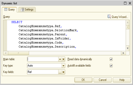
Fig. 202. Arbitrary dynamic list query
Let's take a closer look at the key generation properties.
The Key type property can have the following values:
- Field value. In this case, the data returned by the query has one key field. The field acting as the key is determined by the Key fields property.
The CurrentRow property value type: value type of the field selected by the key field.
- Row key. In this case, the key includes several fields. One field is allowed as well. Use the Key fields property to specify the fields included in the key.
Value type of the CurrentRow property: DynamicListRowKey.
- Row number. Used when no key can be determined for the data returned by a dynamic list query. In this case, the key will be the sequence number of the record from the beginning of the selection.
Value type of the CurrentRow property: Number.
-
Auto. In this case, the platform tries to determine the key type based on the Key fields property and the content of the Main table property:
-
The main table is not specified:
-
The key fields are not set. In this case, the platform will use Row number as the key type.
-
One value is specified in the key fields. In this case, the platform will use Field value as the key type.
-
Several values are specified in the key fields. In this case, the platform will use Row key as the key type.
-
-
The main table is specified:
- The used key type depends on the used table. For the relation of the main table and the used key, see Methods for getting and caching data with a dynamic list.
-
The Key fields property allows you to select one or more fields that are involved in the record key generation. The list of all available fields includes all available dynamic list query fields that comply with the following restrictions:
-
The field can be used for the display in a dynamic list, and also for selection and ordering with the available comparison types: Equal to and In the list.
-
If the field is a key field of the Field value type, the values of this field cannot include Undefined and NULL.
You can change the Read data dynamically property when you select the Field value or Row key value as the key type. The dynamic data reading method depends on the key type selected for the list and the state of the Read data dynamically checkbox:
| Key type | Dynamic data reading is enabled | Dynamic data reading is disabled |
|---|---|---|
| Field value | Method 1 | Method 2 |
| Row key | Method 1 | Method 2 |
| Line number | Not applicable | Method 3 |
For methods of reading data by a dynamic list, see Methods for getting and caching data with a dynamic list.
7.3.1.5. Dynamic list settings
The List settings property. To open the dynamic list display settings form, click Open. Setting up the list is performed in the same fashion as the similar operations in the data composition system.
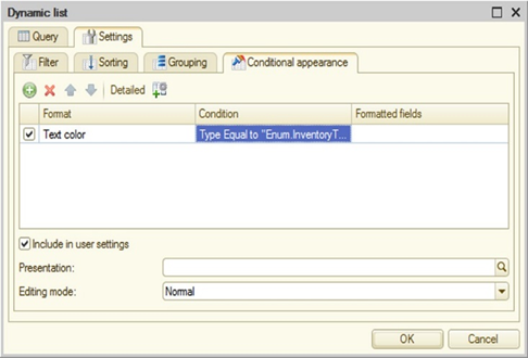
Fig. 203. Conditional appearance of a dynamic list
While customizing a dynamic list in the configuration, the application developer has the following options:
-
Specify the fields for further ordering
-
Describe the list data filter rules
-
Specify the conditional appearance settings
-
Specify the fields for further data grouping
It makes sense to specify the sorting order settings only if the default sorting order does not suit a developer's needs.
Note. Tip. Keep in mind that an inapt selection of sort fields for sorting (as well as for data filtering and grouping) adversely affects the efficiency of the dynamic list selection.
From the perspective of an application developer, the dynamic list settings consist of several parts that are interconnected. The main property through which the dynamic list settings can be managed is the SettingsComposer. This object contains three sets of settings that, when the system is running, determine the final settings that are applied to the dynamic list:
-
Settings. Settings created in Designer mode. TheOrder dynamic list property provides quick access to the Settings.Order property of the dynamic list settings composer. Therefore, the following constructs are equivalent: List.Order and List.SettingsComposer.Settings.Order.
-
UserSettings. Settings modified by the user in 1C:Enterprise mode.
-
FixedSettings. Settings specified in 1C:Enterprise language. Also, this property gets filter values that are passed to the form using its parameters. The properties of the dynamic list Filter, Parameters, ConditionalAppearance provide quick access to the fixed settings of the dynamic list settings composer. In other words, the following calls are equivalent: List.SettingsComposer.FixedSettings.Filter and List.Filter.
When forming the final setting of the dynamic list, various types of settings are combined as follows:
-
If any type of settings is entirely marked as custom, then the custom settings (List.SettingsComposer.UserSettings) are included into the resulting settings. Moreover, if any setting items are marked as unavailable, they are placed into resulting settings from theList.SettingsComposer.Settings property.
-
If any type of settings is marked as custom not entirely but item-wise, then:
-
Items marked as custom will be placed in the resulting settings from the List.SettingsComposer.UserSettings property.
-
Items marked as inaccessible will come to the resulting settings from the List.SettingsComposer.Settings property.
-
-
Fixed settings (List.SettingsComposer.FixedSettings) are added to the resulting settings "as is". Altogether, it is unacceptable when there are settings with the same name to be found in fixed and custom settings, for example, a filter with the same left-side value in its condition.
If there are setting items in the dynamic list settings that are disabled by using the functional options, these items will be removed from the list of available settings when retrieving the dynamic list data.
To control which settings will be available to the user, use the dynamic list settings window.
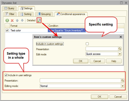
Fig. 204. Managing the inclusion in custom settings
The checkbox at the bottom of the window (seefig. 204) is responsible for placing all types of settings in the settings (normal or quick ones). This option is available for filtering, ordering, grouping, and conditional appearance. If the settings are specified with the Quick choice editing mode, then in the User settings group property of the form table that displays a dynamic list, specify an empty form group in which the items associated with the quick user settings of the dynamic list will be placed. If such group is not specified, quick user settings will not be displayed on the form. You can also explicitly generate the creation of user settings in 1C:Enterprise language using the CreateUserSettingsFormItems() method of the dynamic list extension.
You can also choose an option for placing specific setting items in user settings. This option is available for filter and conditional appearance items (see fig. 204).
If you need to load special settings when opening a dynamic list, you can do this in two ways:
-
Using the UserSettings dynamic list form parameter. The data contained in this parameter will be placed in the dynamic list user settings.
-
Using the UserSettingsKey dynamic list form parameter. If this parameter is specified when opening the form, then the user settings stored in the settings storage with the specified key will be loaded into the dynamic list, which is the main form attribute.
7.3.1.6. Search in dynamic list
A dynamic list located on the form provides an ability to perform an interactive search in the displayed data. Interactive search tools are managed using dedicated form item add-ons (see Supplementing a form item).
Note that redefining value presentation in any way usually results in unpredictable behavior of the dynamic list search for users. Presentations can be redefined by the PresentationFieldsGetProcessing() handler (see Arbitrary data presentation), the OnGetDataAtServer() dynamic list handler (see Additional processing of data received by a dynamic list), the presentation expression of data composition fields, or conditional appearance of a dynamic list or a form. Users might face issues as redefining value presentation is only used when using the dynamic list search string. This type of search uses standard field presentations specified as fields used for generating presentations in thePresentationFieldsGetProcessing() handler of the respective object. That is why, when searching the dynamic list with redefined value presentations, note that the text where the search is performed is not the one the user sees.
Let's review some specific features of using search in a dynamic list:
- To make the search convenient to use (in terms of speed search as well), enable the full-text search for all configuration objects that can be used as the main dynamic list table. Also, the full-text search should include all attributes of configuration objects that can be displayed in a dynamic list and for which a search may be required.
If an object is excluded from the full-text search, then the search mechanism in question will work, but the performance of such search will be extremely low. It is not recommended that you use a search for objects that are not indexed by the full-text search.
-
The application must have a scheduled job that regularly updates the full-text search index.
-
The search is performed not on all columns of the dynamic list (and the configuration object), but only on those columns that are displayed in the table.
-
For dynamic lists with the main table specified, full-text search in the main table is applied. All non-indexed links from the main table will be added to the full-text search results. The full-text search result for the main table is used as a filter by key fields. Also, a full-text search is performed by the fields displayed in the list from other tables (if a full-text search is used for the field and the configuration object). Without full-text search enabled, data can be found but the search itself will be very slow.
If an error occurred while attempting to perform full-text search, the search will be performed without applying full-text search. For example, this can happen when searching for one character and a large number of strings in the infobase starting with this character.
-
If a filter with the Equal to comparison type is used for a field of the main table of the dynamic list, then the filter value will be added to the search query for this table when performing a full-text search.
-
The search string is split into words. The search string must not contain more than 1,000 characters. The number of words obtained during splitting must not be more than 32. The splitting is done in compliance with the following rules:
-
A string is split using space, non-breaking space, and tab characters as separators.
-
After that, each resulting fragment is processed. If a fragment is in the date format (with or without time indication) considering current regional settings of the session, this fragment is perceived as a single word. Otherwise, each resulting substring is considered to represent a separate word.
-
-
For each word, its own set of conditions is generated that are combined "by OR" This set of conditions is generated if either a full-text search for a given word in the table that the field was acquired from has returned at least one object, or the full-text search was not used for this field. Conditions are generated as follows:
-
For a field of the String type, the condition looks as follows: FieldName LIKE %Word%.
-
For a field of the Number type, the condition is given by FieldName=Value, where Value is a word that is cast to the Number type. If the cast is not possible, the field will not be searched.
-
The word is searched for as a substring in the default format for the Boolean type defined for the current session. If the search word is found in a presentation, then the search is performed for the value corresponding to the presentation in which the word is found. In this case, the search does not use presentations that are set using the Format form item property.
-
For the field of the Date type, the condition is given by FieldName>= BegOfDay(Word) AND FieldName<=EndOfDay(Word). If Word is similar to a date in which the year is indicated with one or two digits, the year will be converted to the current century, and this value will be inserted into the search condition.
-
For reference fields, the search is performed in the fields used to generate the link presentation. For each of these fields, the search is performed according to the rules described above. The search does not use the fields used to generate an arbitrary data presentation (see Arbitrary data presentation).
-
A set of conditions for each word is combined "by AND".
-
For values with leading zeros, you can perform a search on either the string with leading zeros, or on the string specified without them.
-
If a dynamic list displays a document list or a document journal, the specified list view interval is also displayed in the form area allocated for displaying the view status for the required dynamic list.
-
The current value search command is not available if the main dynamic list table is a filter criterion.
-
Found pieces of strings are highlighted when displayed in the table.
-
Only one search string is supported for a column. When a new search query for a column that has already been searched for is added, the new search expression will replace the previous one rather than add to it.
-
If a form does not feature such form item add-on asSearch string associated with a table (the Source property of the form item add-on) that displays a dynamic list, press Ctrl + F to open the search dialog box.
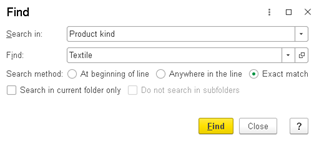
Fig. 205. Search dialog box
Otherwise, if a form features such form item add-on as Search string associated with a table (the Source property of the form item add-on) that displays a dynamic list, click Advanced search to open the search dialog box.
-
When you use the search dialog box, keep in mind the following features:
-
Opening the search dialog box using the key shortcut causes a value of the current cell to be copied into the Search for field, and the value of the Search method radio button to be set to Exact match.
-
Opening the search dialog box by directly typing in the search string of a dynamic list causes the value of the Search method radio button to be set to Anywhere in the line, and the typed text is copied to the Search for field.
-
7.3.1.7. Getting data displayed in a dynamic list
When using dynamic lists, you may need to perform various actions on the data that is currently displayed in the dynamic list, taking into account the applied filters and search conditions. Such actions include processing of displayed information such as: reposting selected documents, setting a specific attribute of selected objects, generating a list of items (with appearance, and so on), for example, available for printing or saving them to a spreadsheet document.
To get the data that is displayed in a dynamic list, use the GetPerformingDataCompositionScheme() and GetPerformingDataCompositionSettings() methods.
Example of getting data:
Scheme = Controls.List.GetPerformingDataCompositionScheme();
Settings = Controls.List.GetPerformingDataCompositionSettings();
TemplateComposer = New DataCompositionTemplateComposer();
CompositionTemplate = TemplateComposer.Execute(Scheme, Settings);
CompositionProcessor = New DataCompositionProcessor;
CompositionProcessor.Initialize(CompositionTemplate);
OutputProcessor = New DataCompositionResultSpreadsheetDocumentOutputProcessor;
Return
OutputProcessor.Output(CompositionProcessor);Getting data into a collection of values (a table or list of values) is done in a similar way (see Data composition result output to a table or value tree).
Getting dynamic list data in this way has a number of features and limitations that need to be considered when developing applications:
-
The following table appearance features are not supported:
-
Row color alternation
-
Header icon
-
Footer icon
-
Footer background color
-
Footer text color
-
Footer font
-
Horizontal position in footer
-
Password mode
-
-
The conditional appearance specified for a managed form is not supported.
-
The data received as a result of executing the GetPerformingDataCompositionScheme() and GetPerformingDataCompositionSettings() methods will not contain any modifications that can be made using the OnGetDataAtServer event handler.
-
When sorting a hierarchical table in ascending order by a field of the Ref type, records containing an empty string are always placed first.
7.3.1.8. Additional processing of data received by a dynamic list
Requirements for dynamic lists may include the display of some additional information that is difficult, inefficient, or impossible to get as part of a dynamic list query. In this case, you can use the OnGetDataAtServer handler of a managed form table that displays dynamic list data. This is an out-of-context form handler that allows you to perform additional processing of data that a dynamic list gets for display.
This event is triggered after a dynamic list has received the data. The event is triggered if at least one row is received by the dynamic list.
Dynamic list settings (filtering (including search), sorting, grouping, conditional appearance, and so on) will be applied to the actual data received by the dynamic list query before it is processed as part of the OnGetDataAtServer event handler.
The OnGetDataAtServer event handler gets three parameters:
-
ElementName. Contains a name of the table which this handler is executed for.
-
Settings. Contains a copy of the full dynamic list settings. Pay special attention to the AdditionalProperties property for this parameter. This property enables the transfer of the required data from a form to the out-of-context handler.
-
Rows. Contains a collection of rows to be displayed by a dynamic list. The collection contains the actual data and the data appearance, but does not contain grouping strings.
As an example, let's examine a list of sales items, which displays the price of an item for the price category specified in the form attribute.
The dynamic list is located in the List attribute. It is displayed in the List table (form item). Configure the price type using the PriceType attribute of the CatalogRef.PriceTypes type.
Note. Note. The examples below are not complete. They are intended to demonstrate various techniques of handling a dynamic list.
The dynamic list query itself is quite straightforward:
SELECT
CatalogItems.Ref, CatalogItems.DeletionMark, CatalogItems.Parent, CatalogItems.IsFolder, CatalogItems.Code, CatalogItems.Description, CatalogItems.SKU, CatalogItems.Supplier, CatalogItems.Type, CatalogItems.Details, CatalogItems.Predefined, CAST (NULL AS Number(10, 2)) AS Price
FROM
Catalog.Goods AS CatalogItemsThis query displays the item catalog itself and "allocates a place" to put the item prices in (the Price column). The rest of the operations are executed in the OnGetDataAtServer event handler:
&AtServerNoContext
Procedure ListOnGetDataAtServer(ElementName, Settings, Rows)
If Settings.AdditionalProperties.Property("PriceType") Then
PriceType = Settings.AdditionalProperties.PriceType;
EndIf;
If NOT ValueIsFilled(PriceType) Then
Return;
EndIf;
Query = New Query;
Query.Text = "SELECT
| Prices.Product, | Prices.Price
|FROM
| InformationRegister.GoodsPrices.SliceLast
(Product IN (&Goods) AND PriceType = &PriceType) AS Prices;
Query.SetParameter("Goods", Rows.GetKeys());
Query.SetParameter("PriceType", PriceType);
Selection = Query.Execute().Select();
While Selection.Next() Do
ListRow = Rows[Selection.Product];
ListRow.Data["Price"] = Selection.Price;
ListRow.Formatting["Price"].SetParameterValue("Format", "ND=10; NFD=2 ; NZ= ");
EndDo;
EndProcedureWhen considering the handler text, pay attention to the following points:
- Since the handler in question is a noncontext one, the price category is retrieved by using the additional properties of the Settings object passed by the handler's parameter. The consequence of this is the fact that when changing the value of the form control displaying the PriceType attribute, one needs to set a new attribute value in the dynamic list settings, and then refresh the list:
List.SettingsComposer.Settings.AdditionalProperties.Insert("PriceType", PriceType);
Controls.List.Refresh();-
Method for receiving the key values for every record that will be displayed in a dynamic list. To do this, use the special GetKeys() method.
-
Data located in Rows.Data is exactly the data set that will be passed to the client application to be displayed by a managed form table associated with a dynamic list. This transfer will be performed following the handler execution.
-
Handling the dynamic list cell appearance (Rows.Appearance) does not differ from the handling the data composition system cell appearance.
If row data is modified in the OnGetDataAtServer event handler, it is recommended that you exclude the fields in which the data is modified from the list of fields used for grouping, sorting, and filtering. Failing to do this will cause an unpredictable behavior when performing grouping, sorting, and filtering (including all types of search). The reason for this behavior is that all the specified operations are performed on the data that will be directly returned by the dynamic list generation query. The result of the OnGetDataAtServer handler is not used for these operations. To set a restriction on the use of a field in a particular operation, use the following dynamic list methods: SetRestrictionsForUseInGroup(), SetRestrictionsForUseInOrder(), and SetRestrictionsForUseInFilter(). The GetRestrictionsForUse...() methods (for the DynamicList attribute type) return the current list of fields that are not available for the execution of a particular operation, provided that the list of restrictions is specified by the SetRestrictionsForUse...()methods.
The data passed to the OnGetDataAtServer event handler has already been processed by the dynamic list conditional appearance. In this case, obviously, the data obtained as a result of the query was used to calculate the conditions. If it is required to change the dynamic list data appearance depending on the result of the OnGetDataAtServer handler operation, change the appearance directly in the handler.
7.3.2. Formatted document
When developing applications, it becomes necessary to allow users to edit texts with formatting (hereinafter referred to as a formatted document). Writing e-mails, various memos, or covering documents exemplify such need.
To perform program processing of a formatted document, use the FormattedDocument object. To interactively modify a formatted document, use a field of the Formatted document field type. To place a formatted document field on a form, create a form attribute of the FormattedDocument type, then create an input field of the Formatted document field kind, and specify the created attribute as data for this field.
It is recommended that you store a formatted document in the infobase as an attribute of the ValueStorage type, in which an object of the FormattedDocument type is placed
To allow the user to modify a document interactively, follow these steps:
-
Create a form attribute of the FormattedDocument type and set the Saved data property for it.
-
Create a form item of the Input field type in the form of Formatted document field and link it with the previously created attribute.
-
When reading form data (the OnReadAtServer() handler), load the document into the form attribute (the SetHTML() method) that needs to be edited, having previously received it from the infobase.
-
Prior to writing the form data (the BeforeWriteAtServer() handler), get the modified document (the GetHTML() method) and put it in the attribute stored in the infobase.
When processing a document, you can use bookmarks. A bookmark describes the position of a character in a document. When determining the position, consider the following features:
-
Document content is treated as a single sequence of characters.
-
Line break is treated as one character.
-
Image is treated as one character.
If the character position the bookmark is linked with changes, the bookmark will trace the position of the linked character. If a character linked with the bookmark is deleted, the bookmark attempts to link with the next character, and if such a character is not found, the bookmark will point to the end of the document. Once an entire formatted document is replaced, all the bookmarks in this document will turn invalid.
With bookmarks, you can get and set the text selection or cursor position in the editor, add and delete text elements in the document (the actual text, image, and line feed).
If the start and end positions coincide when getting a selection, it means that there is no selection and the cursor position is received. The same rule is applied when you try to select a text. If the start and end positions coincide when selecting a text, the cursor position changes without selecting anything. When programmatically modifying the text, the actual display of a selection in the field of a formatted document will not change. If, prior to modifying a text, the selection borders have been retrieved, then after changing the text, the bookmarks can change their position while retaining their placement. In other words, if an insertion occurred inside the selection, then the position of the bookmark describing the end of the selection will be augmented by the size of the inserted text, and so on.
Here is an example of getting and setting a selection in an editor for formatted documents.
// Content is a form
attribute of the FormattedDocument type
// Editor is a form
item of the "Formatted document field" type
// Start is a form
attribute of the Number type Points to the position where the text selection
starts. // End is a form
attribute of the Number type. Points to the position where the text selection
ends. &AtClient
Procedure GetSelection()
StartPosition = 0;
EndPosition = 0;
Controls.Editor.GetTextSelectionBounds(StartPosition,EndPosition);
Start = Content.GetBookmarkPosition(StartPosition);
End = Content.GetBookmarkPosition(EndPosition);
EndProcedure
&AtClient
Procedure SetSelection()
StartPosition = Content.GetPositionBookmark(Start);
EndPosition = Content.GetPositionBookmark(End);
Controls.Editor.SetTextSelectionBounds(StartPosition,EndPosition);
EndProcedureWhen performing deletion operations, the bookmark describing the beginning of the piece to be deleted may turn out to be incorrect. If at the same time it is necessary to retain the starting position of the piece to be deleted, use the starting position of the piece to be deleted. Thus, an example of replacing the selected text with another text would be as follows.
Procedure InsertStringIntoCurrentPosition(Editor, Content, String)
Var Start, End;
Editor.GetTextSelectionBounds(Start, End);
Position = Content.GetBookmarkPosition(Start);
Content.Detele(Start, End);
Start = Content.GetPositionBookmark(Position);
Content.Insert(Start, String);
Bookmark = Content.GetPositionBookmark(Position + StrLen(String));
Editor.SetTextSelectionBounds(Bookmark, Bookmark);
EndProcedureIf there are hyperlinks in a formatted document and the formatted document is displayed in View only mode, you can follow the hyperlinks. They open in a new web browser window.
You can also access the formatted document text programmatically. The text itself consists of objects of the FormattedDocumentParagraph type, which is accessible through the Items property of the FormattedDocument object. Each paragraph in turn consists of objects of the FormattedDocumentText type, the FormattedDocumentLinefeed type, and the FormattedDocumentPicture type (formatted document items). To access this collection, use the Items property of the FormattedDocumentParagraph object. An item border is not necessarily a word border.
For instance, the following example iterates through all paragraphs of a formatted document that contain text and processes each paragraph separately.
Example:
For Each Paragraph In
Document.Items Do
If Paragraph.ParagraphType = ParagraphType.Regular Then
ProcessRegularParagraph(Paragraph);
ElsIf Paragraph.ParagraphType = ParagraphType.BulletedList Then
ProcessList(Paragraph);
ElsIf Paragraph.ParagraphType = ParagraphType.NumberedList Then
ProcessList(Paragraph);
Else
Continue;
EndIf;
EndDo;Processing of formatted document items incorporated in a paragraph may be useful if, for example, you want to remove the entire formatting in italic or bold font.
Example:
Bold = New Font(, , True);
Italic = New Font(, , True);
Regular = New Font;
For Each Item In
Paragraph.Items Do
If TypeOf(Item) = Type("FormattedDocumentLinefeed") Then
Continue;
EndIf;
If Item.Font = Bold Or Item.Font = Italic Then
Item.Font = Regular;
EndIf;
EndDo;In programmatic text processing, the GetItems() and GenerateItems() methods can also come in handy. These methods return an array of the formatted document items. To see the difference between these methods, consider an example of a formatted document that contains the following string: 012 456 890. The string consists of 11 characters, where the characters 4 and 8 are spaces. The task is to get items that are located between positions 2 and 9 of this document.
StartPosition = Document.GetPositionBookmark(2);
EndPosition = Document.GetPositionBookmark(9);
Output = Document.GetItems(StartPosition, EndPosition);
For Each Item In Output Do
Message("Text is " + Item.Text);
EndDo;
Output = Document.GenerateItems(StartPosition, EndPosition);
For Each Item In Output Do
Message("Text is " + Item.Text);
EndDo;The difference between these methods is that the GetItems() method returns all items located between the specified bookmarks (including all border items). Therefore, in this example, the method will return:
Text: 012 456 890Whereas the GenerateItems() method will return the following:
Text: 2 456 8In other words, when using the GenerateItems() method, the system generates a set of items in such a way that it includes only the contents of a formatted document, which is limited to bookmarks.
Keep in mind that the GenerateItems() method modifies the formatted document during its call, and if (in the given example) after calling the GenerateItems() method, the GetItems() method is called once again, the result will be as follows:
Text: 2 456 8The result will be the same even if a set of items returned after calling the GenerateItems() method has not changed.
7.3.3. Planner
7.3.3.1. General information
With the Planner object (hereinafter referred to as the Planner), you can visualize various date-and-time-based operations, with the possibility of repeating these events with a certain periodicity. The Planner displays information and does not store any data in the infobase.
The general procedure is as follows:
-
The data that should be displayed is retrieved from the infobase.
-
This data is displayed in the Planner (as items).
-
The user edits these items.
-
The data of the modified items is updated in the infobase.
With the Planner, you can override the forms used to edit items.
7.3.3.2. Planner structure
7.3.3.2.1. Dimensions
General information
There is always one dimension in the Planner, the timescale. An application developer can also create additional dimensions (the Planner.Dimensions collection), which will allow specifying the purpose of each item. Dimensions do not take precedence over each other, but on the form, they are nested into each other according to the order in which they were added. Each dimension is characterized by a value of an arbitrary type, which can then be used to search for the required dimension.
DimensionSalon
= Planner.Dimensions.Add("Salon");
DimensionItem
= DimensionSalon.Items.Add(Enumerations.SalonType.ForMen);
DimensionItem
= DimensionSalon.Items.Add(Enumerations.SalonType.ForWomen);
DimensionStylist
= Planner.Dimensions.Add("Stylist");
DimensionItem
= DimensionStylist.Items.Add("Smith");
DimensionItem
= DimensionStylist.Items.Add("Collins");
DimensionItem
= DimensionStylist.Items.Add("Johnson");In the sample code above, two dimensions are being added to the Planner:
-
Salon. Describes a type of a hairdresser's shop. The SalonType enumeration with two values is required to determine the salon type. The values are ForMen and ForWomen.
-
Stylist. The last name of a stylist employed in a salon. A string with the stylist's last name will be the value type.
On the form, the Planner will look as follows:
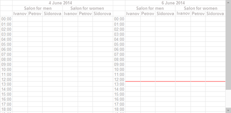
Fig. 206. Two dimensions
If you change the order of adding the dimensions, it will look on the form as follows:
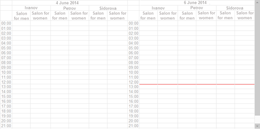
Fig. 207. Changed dimension order
Column/row width and height
The form containing the planner field may change its sizes. The planner field tries to scale down the column width and row height so that all planner data are visible without scrolling. However, this behavior does not always have a positive effect on the usability of the result.
Fig. 208. Strong form item compression
Obviously, using the planner shown in fig. 208 is somewhat inconvenient.
There are several properties managing the planner behavior while scaling down that mitigate such issues:
-
Auto minimum column width. If this checkbox is selected, the system will determine the minimum width of each planner column and will not allow the column to become narrower than the defined minimum width.
-
Minimum column width. If the Auto minimum column width checkbox is not selected, you can manually specify the minimum width of the planner column. 0 means that the column will be compressed to the technical capability.
-
Auto minimum row height and Minimum row height control the height of the planner field row. The behavior is similar to the column width control properties.
If a column or row reaches the manually or automatically specified minimum size, further compression stops and scroll bars appear in the planner field.
If you set the Auto minimum column width and Auto minimum row height properties for the example shown in fig. 208, the minimum size of the planner field will be as follows:
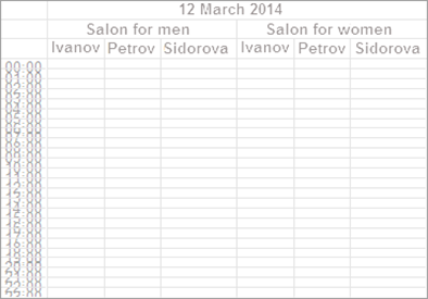
Fig. 209. Minimum size automatic determination
Further decrease in the height or width of the planner field will lead to the appearance of a scroll bar at the relative coordinate.
Docking planner titles
When scrollbars appear in the planner, it becomes necessary to manage the behavior of dimension titles (including the timescale). You can dock titles separately:
-
To dock dimension titles, use the Dock dimension title planner property (FixDimensionsHeader). The Auto value is interpreted at Yes in all kinds of client applications.
-
To dock the timescale title, use the Dock timescale title property (FixTimeScaleHeader). The Auto value is interpreted at Yes in all kinds of client applications.
When the web client is running Microsoft Internet Explorer, both described properties are always interpreted as No, regardless of the actual value.
7.3.3.2.2. Items
There is an item at the "intersection" of dimensions and the timescale. An item has the following main characteristics:
-
Item description.
-
Date and time of the start and the end of an action or event described by the item.
-
Values of all dimensions specified for this planner instance.
-
Item value.
-
Item reiteration options (for repeating items).
In the simplest case, an item is created as follows:
Item = Planner.Items.Add(Date('20140606150000'), Date ('20140606154000'));
Item.Text = "Arrange Tony's haircut";
Dimensions
= New Map;
Dimensions.Add("Salon", Enumerations.SalonType.ForMen);
Dimensions.Insert("Stylist", "Smith");
Item.DimensionValues = New FixedMap(Dimensions);In the sample code above, an item is created that describes an event that starts on June 6, 2014 at 3:00 pm and ends on the same day at 3:40 pm. The event will take place in the men's salon (with the value of the Salon dimension set to ForMen) and the assigned stylist will be Smith (with the Stylist dimension value set to Smith).
Eventually, the item will be displayed on the form as follows:
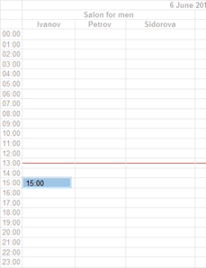
Fig. 210. Item in the planner
The created item has a drawback since it cannot be found in the planner item collection (Planner.Items) with the Find() method. To correct this drawback, specify some unique value as the item value(the Value property) when creating an item, which will later enable the unique identification of the items in the planner.
One option for this unique identifier is the following:
-
Create the Event catalog, with the properties that allow you to fully describe the saved items.
-
Place a reference to the Event catalog item in the Value property of the item being created.
Thus, each item in the planner will be uniquely identified by a reference to the Event catalog item that the data for creating the item was received from.
If not all dimension values are specified when creating an item, the item will not be displayed in the planner.
7.3.3.2.3. Timescale
Timescale placement
In some cases, it is convenient to have the timescale not vertically to the right, but along some other side of the form item that displays the planner. To do this, modify the Planner.TimeScale.Position property. Thus, if you set this property to TimeScalePosition.Top, the planner will look as follows:
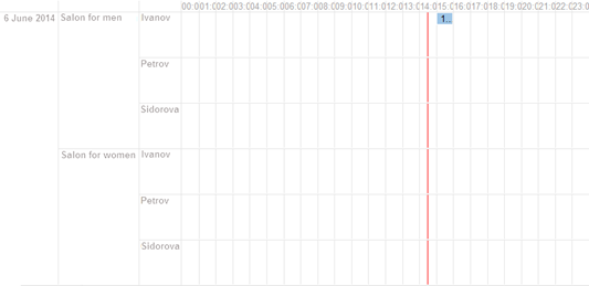
Fig. 211. Horizontal timescale
Items behavior under low disc space
One planner cell (dimension and timescale intersection) can contain several items. fig. 211 shows the placement of one item in a cell. fig. 212 shows the planner with 4 items in one cell (March 12, 2014, shaving salon, hairdresser Smith, time interval 15-16).
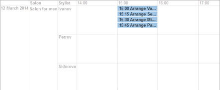
Fig. 212. Several items in a cell
There is enough space in the figure to place all items in height. But there may be not enough space (for example, in case of scale-down of the vertical size of the form item of the Planner field type), and then the planner appearance will change.

Fig. 213. Several items in a cell. Not enough space
The planner cell cannot display all items, so only the items for which there is enough space are displayed, and the remaining items are "hidden" under X more, where X is the number of hidden items in the cell. Such behavior is not always satisfactory.
To settle this issue, use the Items behavior under low disc space form attribute property (ItemsBehaviorWhenSpaceInsufficient). The behavior shown in fig. 213 will take place if the property value is Collapse items. If the Items behavior under low disc space property is set to Show all items, the scaled-down planner will look different.

Fig. 214. Several items in a cell. Different height
In the figure above, note that the height of the line with the Smith dimension exceeds the height of the lines with the Collins and Johnson dimensions. In this way, the planner has made enough place in the cell for all items without displaying the More menu. Note that you can use such planner cell behavior only when the timescale is at the top or bottom (the Timescale position planner property is set to Top or Bottom).
Specifying timescale settings
Apart from changing the position, you can adjust the timescale in a number of ways. First, you can specify units in which the timescale will be measured, and how many units will be placed on the scale before moving to the next column or row. For example, the timescale can be set to quantify time in hours, with 6 hours to be placed in one column or row. In this case, the display of one day in the planner will consist of 4 columns or rows, depending on the timescale display mode: 24 hours in a day and 6 hours in one column or row.
With the timescale displayed on the top, it will look as follows:
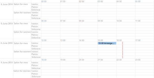
Fig. 215. Timescale frequency
In 1C:Enterprise language, such behavior is coded as follows:
Planner.PeriodicVariantUnit
= TimeScaleUnitType.Hour;
Planner.PeriodicVariantRepetition
= 6;
Planner.TimeScale.Position
= TimeScalePosition.Top;If you do not need hour specifying headers above every 6-hour sequence, you can disable them. Just set the Planner.ShowWrappedTimeScaleHeaders property to False.
The next option for setting up the timescale is to change the current timescale or to set up additional timescales ( thePlanner.TimeScale.Items property). Changing the timescale is necessary when the standard timescale does not suit you for some reason. For example, the timescale unit is set to day, the timescale frequency is set to 7 (week), and the planner displays a time interval greater than 1 week (for example, a month). In such case, the areas of contact of different days, within the frequency of the periodic option, will in no way be visually marked on the form:
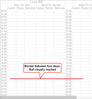
Fig. 216. Border between two time periods
To visually mark the border, add another timescale. The timescale to be added must represent a whole day:
TimeScaleItem = Planner.TimeScale.Items.Add();
TimeScaleItem.Unit = TimeScaleUnitType.Day;
TimeScaleItem.Frequency
= 1;As a result, the border between the two adjacent days will be more noticeable:
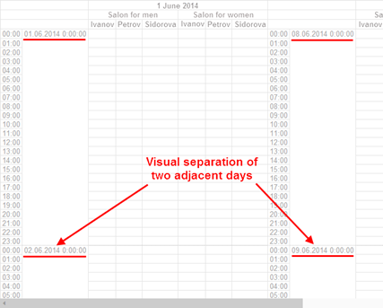
Fig. 217. Separation of two time periods
You can improve the code snippet above by putting the date before the time and changing the date display format:
TimeScaleItem = Planner.TimeScale.Items.Add();
TimeScaleItem.Unit = TimeScaleUnitType.Day;
TimeScaleItem.Frequency
= 1;
TimeScaleItem.Format = "L=; DLF=DD";
Planner.TimeScale.Items.Move(TimeScaleItem, 1);The order of the timescales is determined by their order in the collection. In this example, the added scale follows the default scale, so the newly created scale will be shifted 1 position closer to the beginning of the collection. And by using the Format property, the manner in which the time of day start will be displayed is set. Now, the separation of time periods will become clearer and more conspicuous:
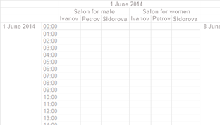
Fig. 218. Changed scale order and display format
Keep in mind that it is impossible to remove an element from the TimeScale collection if it contains only one element. Therefore, you must first add a new timescale, and only then you can remove the automatically added timescale.
7.3.3.2.4. Display periods
The planner can display different time periods. The time period may be one or more, periods may be of arbitrary duration. To set display periods, use the Planner.CurrentRepresentationPeriods collection. Specify display periods based on time. If you set a period using the Planner.CurrentRepresentationPeriods.Add(Date('20140601'), Date('20140601'); construct, the first second of June 1, 2014, will be displayed. To display the day of the end of the period in its entirety, use the EndOfDay() function or explicitly specify the time of the end of the period.
The interaction of the specified display periods and the timescale frequency deserves special attention. All added periods are considered to be one continuous scale, and timescale transfers are processed exactly on this scale. Let's say you want to display 7-day intervals on the timescale for the following set of periods:
-
June 1 – June 5
-
June 10 – June 19
-
June 21 – June 23
Configure the planner as follows:
Planner.PeriodicVariantUnit
= TimeScaleUnitType.Day;
Planner.PeriodicVariantRepetition
= 7;
Planner.CurrentRepresentationPeriods.Clear();
Planner.CurrentRepresentationPeriods.Add(Date('20140601'), EndOfDay(Date('20140605')));
Planner.CurrentRepresentationPeriods.Add(Date('20140610'), EndOfDay(Date('20140619')));
Planner.CurrentRepresentationPeriods.Add(Date('20140621'), EndOfDay(Date('20140623')));
TimeScaleItem = Planner.TimeScale.Items.Add();
TimeScaleItem.Unit = TimeScaleUnitType.Day;
TimeScaleItem.Frequency
= 1;
TimeScaleItem.Format = "L=; DLF=DD";
Planner.TimeScale.Items.Remove(Planner.TimeScale.Items[0]);With this setting, the planner form will look as follows:
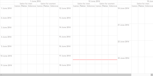
Fig. 219. Timescale transfer with discrete intervals
As you can see in fig. 219, the first 7 days completely covered the first interval (5 days, from June 1 to June 6) and 2 days from the second interval. The second 7 days covered 7 days of the second interval and the third 7 days covered the remainder of the second interval and the entire third interval.
Yet another way to set the display of discontinuous intervals is to set the TimeScaleWrapBeginIndent andTimeScaleWrapEndIndent properties. These properties are specified in the dimension of the PeriodicVariantUnit property. In other words, if the unit of the periodic option is day, then the indent from the beginning or end of the timescale will be calculated in days. For example, you want to display June 2014 in the planner so that only the first 5 (or less) days are displayed in each 7-day interval. To do this, use the following planner configuration code (the sample code will not use the Stylist dimension from the examples above):
Planner.PeriodicVariantUnit
= TimeScaleUnitType.Day;
Planner.PeriodicVariantRepetition
= 7;
Planner.CurrentRepresentationPeriods.Clear();
Planner.CurrentRepresentationPeriods.Add(BegOfMonth('20140601'), EndOfMonth('20140601'));
Planner.TimeScaleWrapEndIndent
= 2;
TimeScaleItem = Planner.TimeScale.Items.Add();
TimeScaleItem.Unit = TimeScaleUnitType.Day;
TimeScaleItem.Frequency
= 1;
TimeScaleItem.Format = "L=; DLF=DD";
Planner.TimeScale.Items.Remove(Planner.TimeScale.Items[0]);With this setting, the planner form will look as follows:
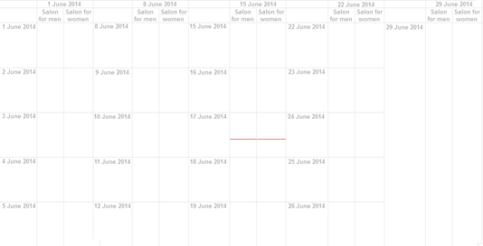
Fig. 220. Indentation at the end of the timescale wrap
In this case, the entire month of June is split into the following time periods:
-
June 1 – June 7
-
June 8 – June 14
-
June 15 – June 21
-
June 22 – June 28
-
June 29 – June 30
Next, from each interval, the number of days (from the beginning and end of the interval) that are specified in the TimeScaleWrapEndIndent and TimeScaleWrapBeginIndent properties (respectively) will be removed, and the resulting intervals will be displayed. The last interval is taken up by the entire indentation, but the beginning of the interval will still be displayed (similar to the behavior when setting the current display periods).
The application developer can independently change the display periods when the user navigates through planner (for example, using the mouse wheel). To do this, handle the OnCurrentRepresentationPeriodChange event. If the StandardProcessing parameter in the event handler is set to False, the display periods specified in the CurrentRepresentationPeriods parameter will not be applied, and the display period will not change.
7.3.3.2.5. Overriding item edit forms
There are two forms in the planner for editing items: quick edit form and item edit form. To override edit forms, use the following events:
-
BeforeCreate. In this event, you can override a form that will be used when creating a new item. The quick item edit form is used by default. Note that Start, End, DimensionValues, and Text parameters in the BeforeCreate event handler of a planner field are returnable. In other words, developers can instantly specify which values will be inserted into an item creation form. You might need this feature when, for example, you cannot create items more often than once in 15 minutes.
-
BeforeStartQuickEdit. In this event, you can override a form that is used for quick item editing. The quick item edit form is used by default.
-
BeforeStartEdit. In this event, you can override a form that is used for regular item editing. The event is triggered in the following cases:
-
A special button is clicked in the system form for quick item editing. If the quick edit form is overridden, then the application developer needs to implement a feature for opening the regular event edit form. In this case, the BeforeStartEdit event is not used.
-
The Edit command is selected in the item context menu.
-
An item displayed in the planner is double-clicked.
-
To get the event editing parameters, use the SelectedItems property of the form item that displays the planner.
To override the form, follow these steps:
-
Open the required form in the appropriate event handler.
-
Set the StandardProcessing parameter of the used handler to False.
7.3.3.2.6. Generating a context menu
When you click the planner field, you can define the action to be performed by default and the menu to be shown if no default action is set or you right-click the field in the first place. To perform specified actions, use the CommandGenerateProcessing event handler of the planner field.
The event handler contains the following parameters:
-
CommandsParameters. Contains a set of values that describe where you clicked.
-
Commands. An array that (after closing the handler) describes the context menu of the planner for this click.
-
DefaultCommand. Contains a description of the command that will be executed when you click a certain area in the planner.
Let's take a closer look at the planner command generation. Use the PlannerCommandDescription object to describe a planner command. The command description is created by the object constructor. The command has several properties:
-
Command. This parameter specifies a command to be created. This parameter can contain the following values:
-
Undefined. Displayed as a separator in the menu.
-
Array. Displays a submenu that consists of commands in the array.
-
PlannerStandardCommand system enumeration value. Describes execution of a standard command.
-
CallbackDescription. Describes a command implemented in 1C:Enterprise language in the application.
-
-
Presentation. Specifies text presentation of a command or submenu. You can specify any text as a separator.
-
Accessibility. Indicates whether the command will be available in this case or not.
-
Picture. Describes the picture to be displayed in the menu.
-
Check. Allows you to select or clear the checkbox of the command in the context menu.
So, you can create completely different commands that generally allow you to flexibly fill the planner context menu:
// create a separator
Separator = New PlannerCommandDescription(Undefined, "-");
// create a command
described in 1C:Enterprise language
UniversalCommand = New PlannerCommandDescription(New CallbackDescription("UniversalCommand", ThisForm, Parameters.Source), "Show source");
SubmenuCommands = New Array;
// create standard
commands
SubmenuCommands.Add(New PlannerCommandDescription(PlannerStandardCommand.CreateItem, "Create"));
SubmenuCommands.Add(New PlannerCommandDescription(PlannerStandardCommand.QuickEditItem, "Change"));
// create a submenu
Submenu = New PlannerCommandDescription(SubmenuCommands, "Additional commands");Now you need to learn how to understand where the mouse button is clicked in the planner. To do it, use the Parameters.Source event handler property. By analyzing the property, you can generate various context menus and default actions. The handler does not receive information on whether the right or left mouse button is clicked. But the developer can specify the action that will be performed once you left-click and the menu that will be shown once you right-click. To do it, use the Commands and DefaultCommands handler parameters.
If, when you leave the handler, the DefaultCommand parameter has a value other than Undefined, then this command will be called when you left-click the corresponding source. The Click... event handler of the planner field will not be called. When you call the command generation handler, the platform already specifies some standard planner command for this parameter. If this parameter value is Undefined or the right mouse button is clicked, this opens the context menu described in the Commands handler parameter. The Click… event handlers include handlers of the following events: DimensionItemClick, TimeScaleItemClick, WrappedTimeScaleHeaderClick, URLClick, and PlannerActionClick.
The command generation handler and Click... handlers for planner areas are called when the following properties are set for a planner field:
-
PlannerCommandSource.DimensionItem and the DimensionItemClick event handler. Set the Dimension scale item hyperlink planner field property.
-
PlannerCommandSource.TimeScaleItem and the TimeScaleItemClick event handler. Set the Timescale item hyperlink planner property.
-
PlannerCommandSource.WrappedTimeScaleHeaderArea and the WrappedTimeScaleHeaderClick event handler. Set the Hyperlink of wrapped timescale header planner property.
7.3.3.2.7. Item actions
A planner item can contain one or more actions. An action can be perceived as an ID (and its appearance) that allows you to perform some operations with a planner item.
You can describe an action using the PlannerItemAction object, which has the following properties:
| Property | Description |
|---|---|
| Visibility | The action will be displayed in the planner item and item editing forms if this property is set to True. |
| Availability | Calls the PlannerActionClick planner event handler upon clicking the action if this property is set to True. |
| Value | A unique action ID. The property content allows you to identify the action in the Actions planner item collection. |
| Picture and Text | Action presentation that will be shown to the user. The text is displayed after the picture. The text can be specified as a simple or formatted string. |
| Tooltip | A tooltip that will be displayed to the user after you hover the pointer over this action. |
| Location | Indicates how an action will be displayed in the planner item (the PlannerItemActionLocation type value): · EndOfItem. Action is displayed in the right/bottom edge area of the planner item depending on the timescale position (horizontal or vertical). · EndOfText. The action is displayed in the area right after the text: § Along the right item border. For horizontal timescale position. § Along the left item border. For vertical timescale position. |
| Font and TextColor | Allow you to set text display parameters. |
To add an action to a planner item, use the Add() method of the Actions collection:
ActionBack = PlannerItem.Actions.Add("ActionBack", "",PictureLib.PreviousStage);
ActionBack.Position = PlannerItemActionLocation.EndOfItem;
ActionBack.Tooltip = "Go to previous stage";After you add an action to a planner item, these actions are automatically displayed:
-
On the planner field.
-
In the system form of quick item editing.
-
In the system form of regular item editing.
For example, if a planner item is generated by the following code snippet in 1C:Enterprise language:
Item = Planner.Items.Add(Date('20200610150000'), Date('20200610154000'));
Item.Text = "Arrange Tony's haircut";
Dimensions
= New Map;
Dimensions.Add("Salon", Enumerations.SalonType.ForMen);
Dimensions.Insert("Stylist", "Smith");
Item.DimensionValues = New FixedMap(Dimensions);
Action = Item.Actions.Add("Change", "", PictureLib.Change);
Action.Tooltip = "Edit customer record";The action specified for this item will be displayed as follows:
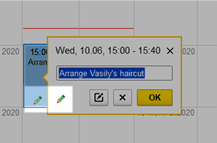
Fig. 221. Item action
To implement your own action, define the PlannerActionClick event handler for the planner field. In this event, you need to analyze the action that was selected in the planner item and perform required actions.
7.3.3.2.8. Iterative Items
Items (see Items) come as occurring once or iterative. Iterative items have a schedule (or rules for repeating the items). To specify the schedule, use the Schedule property. Several items generated as a result of schedule setting form a series of items. Within the series, you can either change the parameters of the entire series, or change the parameters of one specific item of the series.
Iterative items are differently represented in an item collection and when displayed on a form. In the item collection, an iterative item will be given singularly, with the Schedule property being filled.
When displayed on a form, all iterative items will be present. However, the system does not provide an option to process them. At the same time, when you try to edit any item that forms a series, the SelectedItems form item property will contain a collection of planner items that form a series for an item with a schedule. Such items will not have the Schedule property set, but the Parent property will be filled.
The Parent property will refer to the item whose schedule resulted in the creation of a series, part of which is meant to be edited.
If you manually edit one of the items of a series of iterative items in the planner form, then the ReplacementItems property will get filled in the parent event of the series. This collection will show those items of the series the parameters of which have been modified (relative to the parent event). When you create an item data storage structure, keep in mind that this structure must store not only parent items, but also items that have some parameters different from those specified for the series as a whole.
If you edit a replacement item from a series, then the ReplacementDate property indicates the date and time of the initial creation of the series by the system.
7.3.3.2.9. Dragging and planner
When you drag an object to the planner field, use the general dragging scheme (for details, see Drag and drop feature). In addition, consider that the DragCheck events handlers and the Drag planner fields (except for standard parameters) contain parameters that a planner date (the Date parameter) and dimension values (the DimensionValues parameter) above which a pointer and dragged values are located.
To process dragging items executed only inside the planner field, use the InsideDragCheck() event handler of the planner field. As in this case both source and destination are in the same form field, only this event is used for dragging.
The InsideDragCheck() event handler is called in case of selecting an empty planner area upon selecting, dragging, copying, or changing boundaries of one or several planner items. There actions are described by the DragAction handler parameter (the value has the PlannerInsideDragAction type):
| Value | Description |
|---|---|
| Selection | In this case, users select different planner field items with the Shift key pressed. |
| Copying | Users drag a planner item to another field location with the Ctrl key pressed. |
| Editing | Users edit a planner item, for example, changes item boundaries and location. |
| Creating | Users select an empty planner field area for creating a new item. |
The DragParameters handler parameter contains a fixed array whose items describe the planner field item selected by the user to execute an action. Each item is described by the PlannerInsideDragParameter parameter and contains the following properties:
| Property | Description |
|---|---|
| DimensionValues | Mapping that contains planner dimension values for the current item. |
| End | Contains information on the end date and time of the planner item. |
| Start | Contains information on the start date and time of the planner item. |
| Element | Contains a reference to the planner item being edited or copied. In all other cases, contains the Undefined value. |
When it comes to the Start and End properties, remember the following:
-
If you create a planner item by selecting an empty area, these values describe the start and end of the selection area.
-
If you select planner items, these values describe the start and end of the selection area.
-
If you edit a planner item by dragging, these values describe the start and end of the edited item.
-
If you copy a planner item, these values describe the start and end of the copied item.
The BoundaryChangeVariant handler parameter indicates what action you are currently performing with the planner item:
| Property | Description |
|---|---|
| End | Planner item end changes. Planner item end increases or decreases. |
| Start | Planner item start changes. Planner item start increases or decreases. |
| BeginAndEnd | Planner item position changes. |
The last handler parameter is the Cancel return value that describes whether it is necessary to change a planner field in accordance with values in the DragParameters parameter. The change will be made if the Cancel parameter is set to False (a parameter value if the event handler is called). If the Cancel parameter is set to True during the event handler execution, no action will be performed when you exit the event (no item will be created, copied, moved, or resized), and the selection boundaries will remain the same they were before the event handler was called.
So, when you execute an action with the mouse in the planner field, all the necessary information is sent to the InsideDragCheck() event handler:
-
What is selected by the user? For this, the DragParameters event parameter is used.
-
What does the user do? For this, the BoundaryChangeVariant and DragAction parameters are used.
-
Can the user complete the action? For this, the Cancel parameter is used.
7.3.3.3. General model of planner data editing
As mentioned earlier (see General information), the planner does not store data. It only displays data. Therefore, to store information about events in the infobase, create an appropriate data structure, for example, a catalog.
The general procedure is as follows:
-
The general planner parameters, the number of dimensions, the timescale settings, and so on are defined.
-
The current display period of the planner is determined.
-
In accordance with the set display period, data about the displayed information is retrieved from the infobase, and the required events are created in the form item. A reference to the catalog item that stores the data is specified as the Value property for the planner item.
-
When editing or deleting items, the Value property for events that have been modified or deleted is still retained. To do this, use the form attributes that will store the values of the Value property of the modified or deleted items.
New items can be determined by the empty Value property of the item. To do this, iterate through the entire Planner.Items collection.
-
Changing the display period creates items that belong to the new display period.
-
Upon successful completion of operations with the planner, the planner data is synchronized with the data of the catalog that stores the item data.
7.3.4. Charts
7.3.4.1. General information
A chart is a graphical data presentation. A simple kind of chart is a graph. With a graph, you can display successive changes in values over time or depending on changes in other values. For example, you can use a graph to show how the price of goods changes during a year.
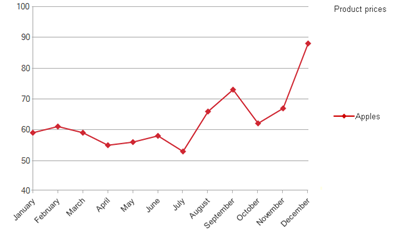
Fig. 222. Graph example
The vertical axis of the graph displays the values of the indicated value (price), with the graph points (months) shown along its horizontal axis. If it is necessary to display various indicators on one graph, their values are shown as separate series.
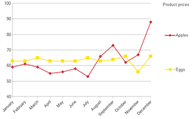
Fig. 223. Example of a graph with two series
In the example above, Apples and Eggs represent the chart series, while months are the chart points.
To visually display different types of data, use different types of charts. Three data types are available for processing of charts:
Chart. Chart can be placed in a form, a spreadsheet document, and the data composition system.
Gantt chart (see Gantt chart). Chart can be placed in a form and a spreadsheet document.
Dendrogram. Dendrogram can be placed in a form and a spreadsheet document.
Further, we will look at each of the main types of charts in more detail.
7.3.4.2. Interactive editing of chart properties
7.3.4.2.1. General information
With the Designer, you can edit properties of the four main areas of a chart:
-
Entire chart.
-
Chart plot area. The area where the chart itself is displayed.
-
Chart title area. The area where the chart title is displayed.
-
Legend area. The area with the chart legend, which indicates displayed data and the way it is displayed in the chart.
For an example of the chart area location, see fig. 246.
To edit chart properties, follow the steps:
-
In a form:
-
Select a form attribute of the required type: Chart, GanttChart, or Dendrogram.
-
Choose the Go to command for the attribute.
-
In the dialog box that opens, select the navigation object: Data – Chart type – Settings.
-
-
In a spreadsheet document:
-
Select a drawing of the required type (to insert a drawing, click Service and settings – Table – Drawings).
-
Open the drawing property palette.
-
In the property palette, you can choose which chart area the palette will display. To do this, use the drop-down list located below the search string in the property palette.
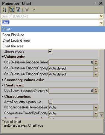
Fig. 224. Selection of the chart configuration area
The drop-down list includes 4 main chart areas described at the beginning of this section.
7.3.4.2.2. Editing chart properties
General information
The set of editable properties for the whole chart essentially depends on the type of the chart itself.
In a typical case, the availability of the chart itself, the chart title visibility, and the display parameters are being modified in the properties of a chart. In the property panel, these parameters are arranged into the Main, Characteristics, and Appearance groups.
You can also set up the series display parameters. These parameters depend on the chart type, yet there are three overall parameters:
-
Show current series in plot area. This parameter indicates how the selected series will be displayed in the chart:
-
Show. The selected series will always be displayed in the chart.
-
Do not show. The selected series will not be displayed in the chart and will not participate in the generation of a merged series.
-
Auto (default value). The selected series will be displayed in the chart if no limit on the number of series is enabled.
-
-
Show in the legend. Specifies how exactly the selected series will be displayed in the chart legend:
-
Show. The series is displayed in the legend.
-
Do not show. The series is not displayed in the legend.
-
Auto (default value). The display of the series in the legend is controlled by the Show current series in plot area property. A series will be displayed in the legend if it is displayed in the chart.
-
-
Trendlines. Specifies the parameters for plotting trendlines for a series (for details, see Trendlines).
If the HideBaseValues property is set to True for the chart, the points with the base value are not included in the calculation of trendlines. In stacked and normalized charts, trendlines are displayed "as is", that is, without stacking.
Charts
For objects of the Chart type, the chart type, data area, display characteristics, and so on are edited in the properties of the chart itself. Also, for the Chart object, you can edit the display parameters for each chart series and the characteristics for displaying points. If you need to change a series to be set up, use the Current series chart property. If a chart uses a limit on the number of series (see Limiting the number of displayed series), the summary series is configured by selecting the Summary value in the Current series property.
The Series order in legend property specifies how the series list will be displayed in the chart legend:
-
Direct. The order of the series in the legend matches the order in which the series were added.
-
Reverse. The order of the series in the legend corresponds to the reverse order in which the series were added.
-
Auto (default value). The order of the series in the legend depends on the chart type:
-
The reverse order is used for the following chart types: horizontal column chart, horizontal 3D column chart, stacked chart, stacked area chart, normalized area chart, stacked column chart, stacked 3D column chart, normalized column chart, and normalized 3D column chart.
-
For the rest of the chart types, the direct order is used.
-
The Values axis property group describes the parameters that can be used to specify the base value of a chart (the Base value property) and the rules for calculating the maximum and minimum values of the chart.
To specify the maximum and minimum chart values, use a few different options:
-
Auto detect (default value). In this case, the maximum/minimum value is determined based on the data set to be displayed by the chart.
-
Use value. In this case, the specific values of the maximum/minimum values are specified by the values in the Maximum value/Minimum value properties.
-
Use value with limitations. In this case, the maximum/minimum values are specified in the Maximum value/Minimum value properties. However, if the actual maximum/minimum values of the displayed data exceed (by module) the specified values, the actual maximum/minimum values will be applied instead.
If the maximum and minimum values of the chart are specified in such a way that the minimum value is greater than the maximum one (for example, as a result of an error in the explicit setting of the values), then the actual maximum and minimum values are calculated as follows:
-
If the value of the Calculate chart maximum value property is equal to Use value, and the value of the Calculate chart minimum value property is not equal to Use value, then when calculating the interval:
-
The minimum value is calculated using the formula: MaxValue*2 – MinValue.
-
The minimum value is adjusted (downward) in such a way as to get a "good-looking" scale.
-
-
If the value of the Calculate chart minimum value property is equal to Use value, and the value of the Calculate chart maximum value property is not equal to Use value, then when calculating the interval:
-
The maximum value is calculated using the formula: MinValue*2 – MaxValue.
-
The maximum value is adjusted (downward) in such a way as to get a "good-looking" scale.
-
-
If the value of the Calculate chart minimum value property is equal to Use value, and the value of the Calculate chart maximum value property is equal to Use value as well, when calculating the interval:
-
The maximum value is calculated using the formula: MinValue*2 – MaxValue.
-
The maximum value is adjusted (downward) in such a way as to get a "good-looking" scale. Note that the maximum value is adjusted even though the maximum value calculation algorithm is set to Use value. This adjustment is made since the maximum and minimum values are specified incorrectly.
-
If numeric values are plotted on the value axis, and a value of the Date type is specified as the maximum/minimum values, the corresponding set value is ignored, and the maximum/minimum calculation is performed automatically.
For charts located in a spreadsheet document, you can specify the spreadsheet document cell area, which will be the data source for the chart. For this, use the Data area property. In this case, you can specify how data series are arranged: in rows or in columns (the Series in rows property).
Thus, if we take a test data set (see Data for charts) as an example, which is used later in this chapter, then:
-
If the Series in rows property is set, then, the values from the following rows will be used as series: 14.03, 15.03, 16.03, 17.03.
-
If the Series in rows property is reset, then the values from the following columns will be used as series: Wholesale buyers, Retail buyers, and Dealers.
Trendlines
Trendline is a geometric visualization of the average values for the analyzed indicators, acquired by using a certain mathematical function. With 1C:Enterprise,you can plot trendlines using the following functions:
-
Linear. Equation used: y=a*x+b.
-
Exponential. Equation used: y=be(ax).
-
Logarithmic Equation used: y=a*ln(x)+b.
-
Power. Equation used: y=a*xb.
-
Polynomial. Equation used: a0+a1x+…+aN(xN), where N is greater than 2.
Note. NOTE. A description of the functions used and their specific features is beyond the scope of this documentation. For the specific behavior of the functions used and their parameterization, see the relevant training materials.
Edit trendlines in a special dialog box.
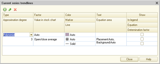
Fig. 225. Trendline setup
For one series, you can specify more than one trendline. To do this, add a new trendline in the dialog box. When adding, specify the following information:
-
Type. What kind of function will be used to plot the trendline. The list of functions is given above.
-
Approximation degree. Determines the value of N if the trendline type is a polynomial function.
-
Factor. What will be the interpolation value (factor)?
-
Point number. Factor will be the ordinal number of the point on this chart (numbering starts from 1).
-
Point value. Factor will be the Value point property cast to the Number type. If the values of the series or points are dates, and the Factor property for the trendline is set to Point value, then when calculating the trend, the dates are converted to numbers as the number of days that have passed from the minimum date for this chart. The number of days can be fractional.
-
Auto (default value). Factor will be either a point number or value, depending on the values of all points.
-
-
Value in stock chart. In the stock chart and the stock candlestick chart, each point is set by four values: opening price, maximum price, minimum price, and closing price. This property indicates which values will be used for interpolation.
-
Color. Specifies the trendline color. If the color is set to Auto (to do this, clear the set value with the clear value button), then the color of the trendline will be:
-
If several series are displayed, it is equal to the color of the series for which the trendline was created (accordingly, when the color of the series changes, the color of the trendline changes).
-
If a single series is displayed, it is black.
-
-
Marker. Specifies the marker form. The marker is displayed only at the beginning and at the end of a trendline.
-
Line. Specifies the style of the line the trendline is plotted with.
-
Text. Trendline name to be displayed in the chart legend.
-
Equation area. This property describes where and how the actual equation describing the plotted trendline (if it is specified) will be displayed.
-
The Show property group specifies how the trendline characteristics will be displayed:
-
In legend. Whether or not the trendline will be present in the chart legend.
-
Equation. Whether or not the actual interpolation equation will be shown within the chart.
-
Determination factor. Controls the display of the determination factor. The determination factor evaluates the interpolation function with regard to the specified data and allows you to evaluate the applicability of the used function to the used data.
-
Reference lines and bands
When plotting charts, you may need to visually highlight a certain area of the chart, for instance, to accentuate a certain month or product on a sales graph. It is allowed to highlight points and intervals in the following chart types: stock chart (all types), column chart (all types), line chart (all types), scatter chart, bubble chart, radar chart (all types), and gauge chart.
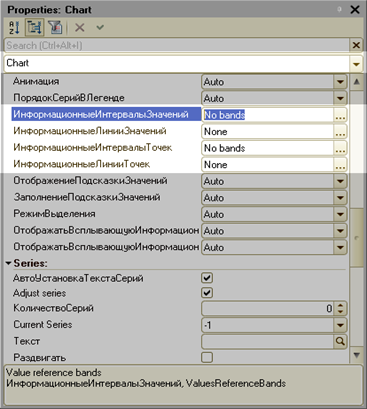
Fig. 226. Reference bands and lines
To manage the highlighting of the chart itself, use the following properties:
-
Value reference bands (ValuesReferenceBands) and Point reference bands (PointsReferenceBands). Allow you to highlight one or several value bands along the corresponding axis. A band is a rectangle of a certain color that highlights a specific range of values on the corresponding axis.
-
Value reference lines (ValuesReferenceLines) and Point reference lines (PointsReferenceLines). Allow you to plot one or several lines that follow some specific values of the corresponding axis.
Each of these properties has a special editor that you can use to set up bands and lines.
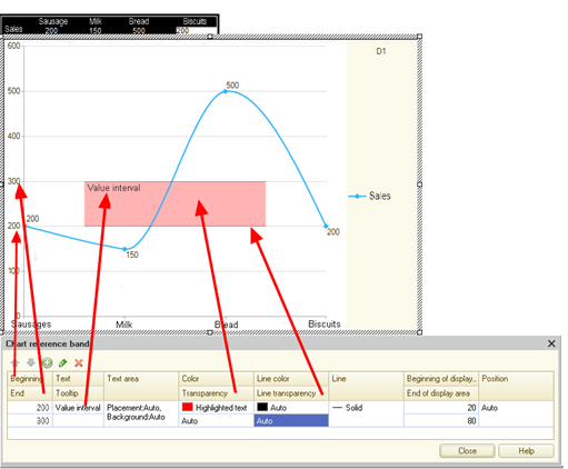
Fig. 227. Reference band
For reference bands, use the following properties (an example is shown in fig. 227):
-
Start and End. Describe a value or point band. The types of values and the values themselves depend on the data in use.
-
Text. A band label.
-
Tooltip. Additional information that appears when you hover the mouse over the band.
-
Text area. Allows you to specify the band label display format.
-
Color and Transparency. Allow you to set the band display color and the color transparency. Transparency is set to a value between 0 (fully opaque) and 100 (fully transparent).
-
Line, Line color, and Line transparency. Allow you to specify how to display the band border. Transparency is set in the same way as for the band display color.
-
Display area start and Display area end. Allow you to manage the size of the band display area. By default, a band is displayed starting from the corresponding axis and up the entire height of the chart. In the example in fig. 227, the default band display is from the Sausage point (the values axis itself) to the Biscuits point (the border of the plot area). Nonetheless, this visualization style is not always appropriate. Then, using these properties, you can set the "indent" from the lower and upper band borders (in percent). The figure shows that the indent is set to 20% from the lower band border and 20% from the upper band border.
A set of properties that is used to visualize a reference line is in some ways different.
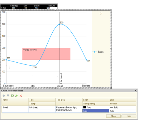
Fig. 228. Reference line
On the whole, these properties are similar to the reference band properties of the same name. It is worth to specifically mention the following properties:
-
Value. Specifies the value for which the reference line will be plotted. The types of values and the values themselves depend on the data in use.
-
Position. Specifies where the reference line will be plotted: either directly "by value" or between the previous and current values.
Value tooltips
With charts, you can set up how the tooltip is shown when the pointer is on the chart. There are several properties to set up the tooltip.
The Value tooltip display mode property (ValuesToolTipShowMode) sets when the chart will display the tooltip:
-
Show on hover. The tooltip is shown when the pointer is on the value. While the pointer is moving, the tooltip is hidden.
-
Show for the nearest value. The tooltip is shown for the nearest value. The tooltip is displayed near the value. When the pointer is moving, the animated tooltip is moving between the values.
-
Do not show. The tooltip is not shown.
-
Auto. Depending on the chart type, it is interpreted as follows:
-
Show for the nearest value for (usual, area, and radar) graphs and scatter charts.
-
Show on hover for other chart types.
-
If a chart is set to Show on hover, the tooltip (together with the pointer) will look as follows:
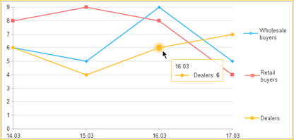
Fig. 229. Show on hover
If a chart is set to Show for the nearest value, the tooltip will be show, for example, in the following situation:
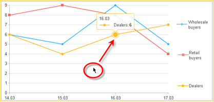
Fig. 230. Tooltip for the nearest
If several series are shown in the graph, it may be necessary for the tooltip to show the information on all series in the selected point at once. The Value tooltip fill mode chart property (ValuesToolTipFillType) controls this feature:
-
One value. In this case, the tooltip shows the value that the pointer points to.
-
All point values. In this case, the tooltip shows the values for all series in this point.
-
Auto. Interpreted as One value.
For an example of displaying a tooltip with one value, see fig. 229. If the tooltip display mode is All point values, the tooltip will look as follows (the tooltip display is set to Show for the nearest value):
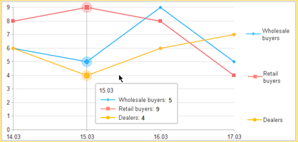
Fig. 231. All point values
If the chart is set to display all point values, the tooltip is shown as follows:
-
The tooltip is always displayed in the Show for the nearest value mode.
-
To control the delay from the moment the pointer moves to the tooltip display, use the Value tooltip display mode property.
You can also specify a tooltip text as a formatted line. For example, if you set a presentation as the Special value line (italics) for the Retail buyers series value at point 16.03, the chart will look as follows:
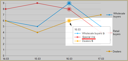
Fig. 232. Tooltip formatting
Also note that the platform automatically adds a series marker to the tooltip at the beginning of the line if no tooltip is set for the value or the All point values mode is enabled. If the tooltip shows one value, the tooltip frame has the color of the series.
To set the tooltip, use the ChartValue.Tooltip property or the relative parameters of the chart value setting methods.
When displaying a tooltip, you may need to select all values of the point whose value the pointer points to. To control this feature, use the following properties: Show pop-up point reference line (ShowPointsPopupReferenceLine) and Show pop-up value reference line (ShowValuesPopupReferenceLine). If such representation is allowed, the reference line will be shown when the tooltip is displayed. For an example, see fig. 230. If the display of the reference line is not allowed, the representation will be as in fig. 231.
Selecting in charts
In charts, you can interactively select some chart elements and process the selected data. To choose which elements will be selected in a chart, use the Selection mode chart property (SelectionMode):
-
Select values. Allows you to interactively select chart series and values.
-
Select points. Allows you to interactively select chart points. The mode is available only for the charts that support points axis and do not support series axis (line, step, stacked line, area, stacked area, and normalized area charts; all bar, column, and radar charts; and stock and open-high-low-close charts). In other chart types, the values is interpreted as No.
-
No. You cannot interactively change the selection in the chart.
-
Auto. Interpreted as Value selection.
You can also select information in the chart by left-clicking the required legend series.
If selection is enabled for the chart, you can handle the selection result using the OnActivate event handler. This event is available for a form field extension for a chart filed.
The selection in the chart is performed as follows:
-
Selection is performed:
-
By single left-clicking the value
-
By single left-clicking the chart series in the legend
-
By selecting a rectangular area in the chart plot area
-
-
If the selection is performed with Ctrl pressed, the selected object is added to the selection or removed from it (if this object was added to the selection earlier).
-
If the selection is performed without Ctrl pressed, the new selection becomes the only one.
In case of any selection, the chart is displayed as follows:
-
If nothing is selected in the chart, the chart is displayed as usual.
-
If some data is selected in the chart:
-
Series with selected values are shown in the color specified for the series. Selected values are displayed with a border.
-
Series with no selected values are shown in the paler color specified for the series.
-
Interactively modifying chart values
In 1C:Enterprise, you can interactively edit data displayed in charts, that is, directly in the chart. This option can be helpful in various scenarios, for instance, when you execute "what if" scenarios or plan something.
Interaction modification of chart values is managed independently for three objects which are involved in the chart generation:
-
Value edit mode chart property. This property defines whether the default chart values can be changed interactively (for the entire chart). If it is set to Auto, no interactive modification is available for the selected chart (this value is interpreted as Not used).
-
Value edit mode chart series property. This property defines whether values of a particular series can be edited. If it is set to Auto, availability of an edit option is defined in the chart settings.
-
ChartValue.EditState chart value property. It enables or disables editing of a specific chart value. If it is set to ChartValuesEditMode.Auto, availability of an edit option is defined in the series and chart settings, accordingly.
Therefore, it is evident that the value editing settings allow very flexible control of interactive editing. For example, you can implement the following chart:
-
Display actual sales figures for the previous year broken down by months. Obviously, you cannot edit this data.
-
Display sales effected in the current year, while:
-
You cannot edit actual sales figures for past months.
-
Of course, you can edit sales figures for the remaining months to the year end. In this case, you edit sales targets for the remaining period before the year expires.
-
You can use the OnValueEdit form item event handler to edit values. The handler is called both during value modification and upon termination or cancellation of value editing. To determine a currently executed action, you can use the EditState handler parameter:
-
Completed. Editing has been successfully completed. The ChartValue handler parameter contains the new value.
-
Canceled. Esc is pressed while editing the value. The ChartValue handler parameter contains the old value before editing has been started.
-
InProgress. The value is being modified by the user. The ChartValue handler parameter contains the current value.
See the mouse pointer to know whether you can edit a value. When you move the mouse pointer over an area where interactive value editing is allowed, its appearance changes. To edit, left-click the marker (or column edge) in the chart and move the marker (or column edge). Note the following points:
You can edit in 8.3.15 incompatibility mode for column charts, graphs, step charts, and area charts. Editing is available as well for summarized and normalized series. To edit, drag it with a mouse.
-
Left-click to lock a form (if deemed necessary) and start editing.
-
When you move your mouse, the current point value is modified depending on the selected scale range and the mouse movement distance. In normalized charts, the overall amount used for normalization purposes is considered.
When you move the mouse, OnValueEdit form item event is generated with a new value and the EditState parameter set to InProgress.
-
During interactive editing of values, scale values are recalculated and the chart is redrawn.
-
If you cancel editing by pressing Esc, the chart is set to the value available before the editing is started.
The OnValueEdit event is generated with the previous value and the EditState parameter set to Canceled. Editing is over.
-
If editing is successfully completed (left mouse button is released), the OnValueEdit event is generated with a new value and the EditState parameter set to Completed.
-
During the last stage, the OnChange form item event is generated, while the Modified property is assigned to the form.
Secondary value scale
Technically, a charting mechanism ignores units of measure displayed when it generates respective charts. However, a user who uses such chart cannot absorb information properly if the chart and the scale specify values in dissimilar units of measure. As an example, consider a chart which describes sales of a product in quantitative and monetary terms or when amounts are specified in different currencies. Another example of difficulties that may arise when information is incorrectly display is a chart where series values are specified in similar units of measure, while the value order is significantly different.
To address these problems, use a secondary value scale. This can be done as follows:
-
Add a secondary scale for one or more series.
-
Whenever necessary, modify secondary scale parameters.
It can be added both for an ordinary chart (all options) and column chart (all options).
Secondary scale parameters are set similar to properties of the main value scale. These parameters are grouped in the chart properties panel in Secondary values axis.
In the properties of the required series, set the Used value scale property to Secondary. The chart will display a secondary value chart. Consider an example.
You sell a product with respective figures broken down by months (January, February, and March). The price is 150 rubles. The sales volume is 2,500, 6,000 and 6,300 pcs (respectively). You need to have both graphs in a single chart. If you use a single scale, the graph will be displayed as follows:
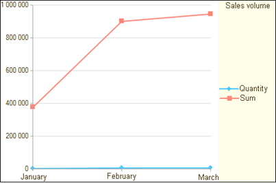
Fig. 233. Single scale
It is obvious that it is almost impossible to use this chart, as the sales graph in quantitative terms cannot be read.
For the secondary scale, use the default settings and assign it to the Sum series. The graph is now more informative:
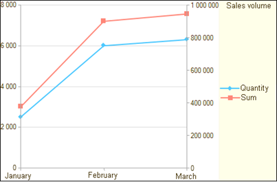
Fig. 234. Two scales
You can read graphs being part of a chart (both in quantitative and monetary terms) and see the axis scale and values.
If only two series are displayed on a chart with a secondary scale, you can use the same color to display chart axes that is assigned to the said series. To do this, you can use the Value scale and Secondary value scale chart plot area properties.
Also note that a secondary scale can be displayed as a backup vis-a-vis the main value scale. To do this, select the Secondary value scale property (for the chart plot area) and in the dialog box that opens, set the Display property to Visible. Therefore, if no series is assigned to a secondary scale, it will be used as a backup for the main chart value scale.
Chart integration
When you use dissimilar items per chart, in addition to a secondary value scale (for details, see Secondary value scale), you may need to display certain items using a different chart type. Consider an example.
You have a spreadsheet with certain sales figures.
| Apples | Pears | Melons | |
|---|---|---|---|
| June | 50 | 35 | 0 |
| July | 60 | 40 | 0 |
| August | 70 | 37 | 56 |
| September | 65 | 38 | 70 |
If this data is displayed as a column chart, you will have the following chart
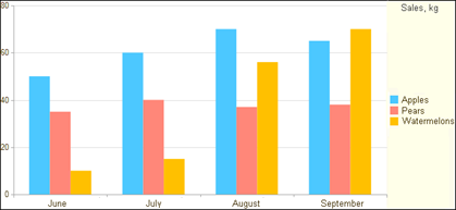
Fig. 235. Original chart
However, let's assume that you need to display melon sales separately. The resulting chart will be as follows:
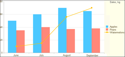
Fig. 236. Modified chart
To create this chart, follow these steps:
-
Select the Watermelons series: in the Current series chart property, select the Watermelons value.
-
Set the Graphic display kind series property to Graph.
You can select a different series graph type, if the entire chart is a graph (all options) or a column chart (all options). You can select the following chart kinds as other kinds: line chart, step chart, area chart, column chart, and 3D column chart.
1C:Enterprise introduces no restrictions as to the number of series with a graph type that differs from that of the chart in general. You can modify the graph type for one or more series.
Series accumulation
The accumulation mode in a chart can be set by the following two methods:
-
Select the "accumulation" chart type (the Chart type property in the chart settings). This type of chart will have "stacked" in its name, for example, Stacked column chart or Stacked graph. As such, accumulation is applicable to all series displayed on a chart. Specific information on "accumulation" charts is given in the section about different chart types (for details, see Charts).
-
Select accumulation mode independently for a proper series displayed on a chart. Individual accumulation mode is managed by the following two series properties: Accumulation mode and Accumulation group. This section deals with these properties.
For example, let's consider the following spreadsheet:
| Apples | Pears | Melons | Rockmelons | |
|---|---|---|---|---|
| June | 50 | 35 | 0 | 0 |
| July | 60 | 40 | 0 | 0 |
| August | 70 | 37 | 56 | 70 |
| September | 65 | 38 | 70 | 90 |
Let's display this data using an ordinary column chart:
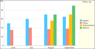
Fig. 237. Ordinary column chart
Let's assume that you need to display sales figures for apples and pears in a single column (with accumulation). To do this, for each of these series, set the Accumulation mode property to Stacked or Normalized stacked.
As a result, you will have the following graph:
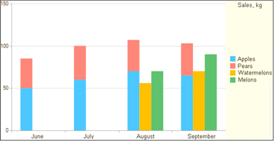
Fig. 238. Accumulation enabled
Similarly, follow the above steps when a chart is displayed with accumulation in general, while you need to exclude a specific series from the accumulation mode. For this, set the Accumulation mode property to Unstacked. This is the case, for example, when you need to display a specific series on a stacked chart with another chart type without prejudice to a displayed stacked chart. If the Accumulation mode property is set to Auto, series accumulation mode is defined by the chart type.
Let's assume that you need to display a chart in a way that apples and pears are in a single column in a column chart, while the other column includes melons and watermelons. To do this, display your spreadsheet as a stacked chart.
The resulting chart will be as follows:
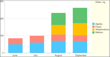
Fig. 239. Stacked column chart
Now for each of the series (Apples, Pears, Melons, and Rockmelons), specify the Accumulation group property as follows:
-
For the Apples and Pears series, set it to From trees.
-
For the Melons and Rockmelons series, set it to From ground.
As a result, you will have the following chart:
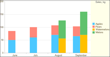
Fig. 240. Accumulation groups enabled
Therefore, the Accumulation group series property defines how the accumulation series will be summed up. Series that have the same value in the Accumulation group property will be summarized jointly. The accumulation group name can be set at the user's discretion. It only identifies the group for the platform and is not displayed to the user.
7.3.4.2.3. Editing plot area properties
When you edit the plot area properties, you can describe how the scale of points, series, and values will be visualized. To do this, use respective plot area properties: Point scale, Series scale, and Value scale.
To configure each of the scales, use the chart scale editor.
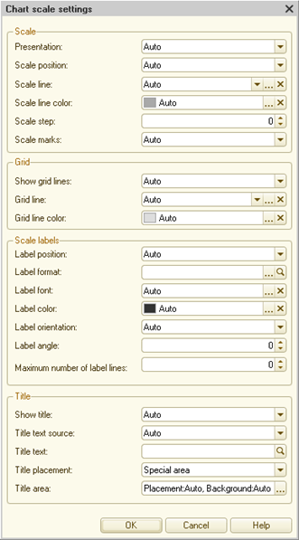
Fig. 241. Chart scale editor
Let's take a closer look at the editor's options.
Scale settings
The Scale position property. Sets the chart scale position:
-
Auto. For the value scale, use Edge. For the point scale in scatter and bubble charts, use Edge. Otherwise, use Base value.
-
Base value. The scale is displayed on the base value of the perpendicular axis:
-
For the point scale, it is positioned on the base value of the value axis.
-
For the value scale, it is positioned on the base value of the point axis.
-
-
Edge. The vertical scale is placed to the left of the chart, while the horizontal one is placed below the chart.
The Scale line and the Scale line color properties specify the style and color of the scale line. You can select the line style from the drop-down list or configure it in the dialog box. To configure the color, use the color selection dialog box.
The Scale step property allows you to specify the scale step value. If discrete values are plotted on the scale, the step value is rounded to the nearest integer:
-
If scale step = 1, each step is output.
-
If the scale step is 2, every even step is visualized, and so on.
-
If the value is assigned to 0, the scale step is calculated automatically.
The Scale marks property allows you to specify the position of the chart scale marks relative to the scale:
-
Outside. Marks are displayed on the outer side of the scale.
-
Inside. Marks are displayed on the inner side of the scale.
-
Centered. Marks are placed at the same distance from both sides of the scale.
-
None. Scale marks are not displayed.
-
Auto:
-
Scale marks are displayed on the outer side if chart labels are displayed on the outer side.
-
Scale marks are displayed on the inner side if chart labels are displayed on the inner side.
-
Grid settings
Show grid lines property allows you to manage the grid line display.
-
Show. Shows grid lines.
-
Do not show. Hides grid lines.
-
Auto:
-
Grid lines are shown for value and point scales in scatter and bubble charts.
-
All other charts do not display grid lines.
-
The Grid line and Grid line color properties specify the grid line style and color, respectively. You can select the line style from the drop-down list or configure it in the dialog box. To configure the color, use the color selection dialog box.
Scale label settings
The Label position property sets the position of labels to the scale:
-
Do not show. Hides scale labels.
-
Inside. Scale labels are displayed on the inner side of the scale.
-
Outside. Scale labels are displayed on the outer side of the scale.
-
Auto. Interpreted as Outside.
The Label format property allows you to specify a format string for converting the scale value to text.
The Label font and Label color properties allow you to specify the scale label font and color (respectively).
The Label orientation property specifies the scale label orientation:
-
Horizontal. The label text is displayed horizontally.
-
Vertical. The label text is displayed vertically.
-
Custom angle. The label text angle is specified by the Label angle property:
-
The positive property value means rotation around the left label edge. With 0 degrees, the label is positioned on the right side. With 180 degrees, the label is positioned on the left side.
-
The negative property value means rotation around the right label edge. With 0 degrees, the label is positioned on the left side. With 180 degrees, the label is positioned on the right side.
-
0 degrees is the same as Horizontal.
-
90 degrees and 90 degrees are equivalent to the Vertical value with different text baseline positions.
-
-
Auto. Labels will be displayed horizontally if the chart location allows so. Otherwise, labels will be displayed vertically.
The Maximum number of label lines property allows you to specify the maximum number of text lines to be used to display labels. If the value is 0, the number of lines will be calculated automatically.
Title settings
The Show title: property sets how the title is displayed:
-
Auto. Shows a title if it contains text to be displayed.
-
Do not show. Hides a title.
-
Show. Shows a title.
The Title generation property specifies how the scale title is generated:
-
Auto. If the Title text property contains some text, the property value is used. Otherwise, the text is generated based on the chart data.
-
Use text. The text specified in the Title text property is used.
-
Auto text. The text is generated based on the chart data.
The Title text property allows you to explicitly specify the scale title.
The Title position property specifies the area to output the title:
-
With axis. The title is placed next to the chart axis.
-
Plot area. The title is placed in the plot area.
-
Special area. The title is placed in the special area:
-
For the horizontal axis, it is placed below.
-
For the vertical axis, it is placed on the left.
-
The Title area property allows you to configure a label area for a chart scale.
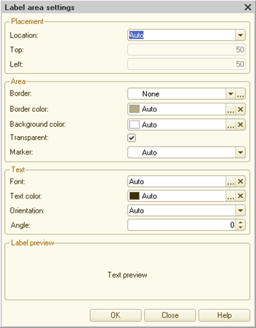
Fig. 242. Label area settings
When configuring a label area, keep in mind certain rules for the title area position. These rules are determined by the values of the Title position property (the chart scale settings dialog box) and those of the Position property group (the title area settings dialog box):
-
The Title position property is set to Special area. The Location value of the title settings area:
-
If the axis is positioned horizontally:
-
Auto, Center, Empty area, Edge, Edge auto, or Edge inside. A label is displayed in the special area, centered in the middle.
-
Left top or Left bottom. A label is displayed in the special area, on the left.
-
Right top or Right bottom. A label is displayed in the special area, on the right.
-
Coordinates. A label is displayed in the special area, with the Top and Left properties specifying the offset of its position inside the special area. In this case, 0 is the minimum value for the corresponding coordinate, and 1 is the maximum value. Thus, a value of 0.5 is the middle of the special area allocated for displaying the title.
-
-
If the axis is positioned horizontally:
-
Auto, Center, Empty area, Edge, Edge auto, or Edge inside. A label is displayed in the special area, centered in the middle.
-
Left top or Right top. A label is displayed in the special area, at the top.
-
Left bottom or Right bottom. A label is displayed in the special area, at the bottom.
-
Coordinates. A label is displayed in the special area, with the Top and Left properties specifying the offset of its position inside the special area. In this case, 0 is the minimum value for the corresponding coordinate, and 1 is the maximum value. Thus, a value of 0.5 is the middle of the special area allocated for displaying the title.
-
-
The Title position property is set to Plot area. The Location value of the title settings area:
-
Edge and Edge auto. The vertical axis label is positioned to the left of the plot area, whereas the horizontal axis label is positioned at the top of the plot area.
-
Edge inside. The vertical axis label is positioned to the left of the plot area, whereas the horizontal axis label is positioned at the bottom of the plot area.
-
Center. A label is positioned in the center of the plot area.
-
Auto. The same as Empty area.
-
Top left. A label is positioned in the top left corner of the plot area.
-
Bottom left. A label is positioned in the bottom left corner of the plot area.
-
Top right. A label is positioned in the top right corner of the plot area.
-
Bottom right. A label is positioned in the bottom right corner of the plot area.
-
Coordinates. A label is displayed in the special area, with the Top and Left properties specifying the offset of its position inside the special area. In this case, 0 is the minimum value for the corresponding coordinate, and 1 is the maximum value. Thus, a value of 0.5 is the middle of the special area allocated for displaying the title.
-
Empty area. The system seeks for a suitable place within the plot area.
-
-
The Title position property is set to With axis. In this case, the behavior is similar to that when the title position is set to Plot area value, but instead of the plot area, the area directly next to the corresponding axis is selected. Depending on the axis position, the area has the following size and position:
-
The axis is positioned horizontally: the area is a rectangle whose width is equal to the axis length and whose height is twice the label height.
-
The axis is positioned vertically: the area is a rectangle whose width is twice the label height and whose height is equal to the axis length.
-
-
7.3.4.3. Charts
7.3.4.3.1. General information
The form attribute of the Chart type is displayed on the managed form using the form field of the Chart field format.
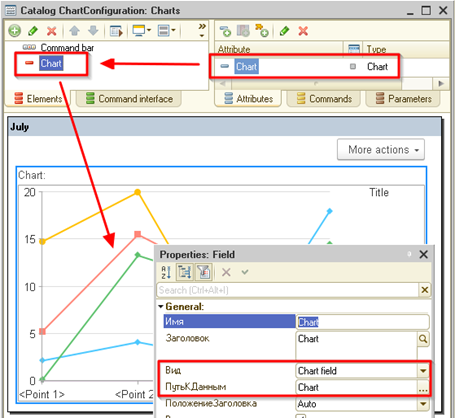
Fig. 243. Chart on form
To configure chart properties, use a special form. You can open it from the properties panel (by clicking Open from the Settings property) or by clicking Go to from the context menu of the form item of the Chart field format. If you open the settings form by clicking "Go to", then in the Go to object dialog box, select not the chart itself but its settings form.
Fig. 244. Navigation to the chart settings
The settings form allows you to fine-tune both the chart as a whole and its individual areas.
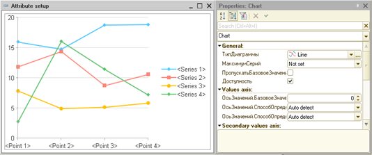
Fig. 245. Configuration form
The Chart type property specifies how the data is displayed. The specific chart properties depend on the selected chart type. The chart field consists of the following areas:
-
Plot area
-
Legend area
-
Title area
By default, these areas are arranged as follows:
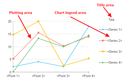
Fig. 246. Chart areas
The plot area can contain the following components:
-
Point scale
-
Series scale
-
Value scale
-
Data table (spreadsheet)
On the chart, these components can be arranged as follows:
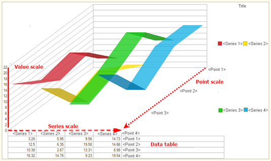
Fig. 247. Chart components
To display a data table, enable ShowDataTable in the chart plot area. This property is not available for all chart types.
7.3.4.3.2. Operations with charts using 1C:Enterprise language
Operations with chart data
You can link the Chart object to data using either of the two following methods.
The first method is based on the possibility to generate chart series and points, as well as to set their values, directly from 1C:Enterprise language. The example below generates a series of ten points for a chart with random data.
Generator = New RandomNumberGenerator;
Chart.Clear();
Chart.Refresh = False;
Series = Chart.Series.Add("Series");
For Counter = 1 To 10 Do
Point = Chart.Points.Add("Point No " + String(Counter));
Value = Generator.RandomNumber(1, 10);
Chart.SetValue(Point, Series, Value);
EndDo;
Chart.Refresh = True;With this method of filling data, the Transpose() method is available, which allows you to swap the chart series and points. The swap option may come in handy when changing the chart type. For example, a pie chart displays values represented as a single point and a set of series. To show the same data on the graph, one needs to swap the series and the points. The AutoTransposition property enables a mode in which the need for swapping is determined automatically, depending on the chart type and data structure.
The second method to fill in the chart data is by using the DataSource property. A value table or a spreadsheet document cell area can be used as a source.
Query = New Query;
Query.Text = "SELECT
| SalesTurnovers.Period AS
Period, | SalesTurnovers.TurnoverAmount
AS Revenue
|FROM
| AccumulationRegister.Sales.Turnovers(, , Month, ) AS SalesTurnovers
|
|ORDER BY
| Period";
QueryResult = Query.Execute();
SourceDataTable = QueryResult.Export();
Chart.SeriesInRows = False;
Chart.DataSource = SourceDataTable;If you specify a key value for a series or point when you create it, you can later search for this series or point. The key value is contained in the Value property:
Point.Value = 1;
Series.Value = "Series1";The SetPoint()/SetSeries() methods allow you to find a chart point or series by key value. Having defined a series and a point, you can read the current value at the point using the GetValue() method or set a new value using the SetValue() method.
// Search for a point
Point = Chart.SetPoint(4);
// Search for a series
Series = Chart.SetSeries("Series1");
// Determine the chart
point value
Value = Chart.GetValue(Point, Series).Value;
// Change the chart
point value
Chart.SetValue(Point, Series, Value + 10);The SetPoint()/SetSeries() methods generate a new chart point (chart series) if a point (series) with the specified key value is not found. For a new series, fill in the Value property. This feature is useful when filling a chart with data.
Let's suppose you need to visualize sales data for various items on a monthly basis. Items form chart series, and periods are represented by points. When iterating the data received from a query, a link to the same item can encounter multiple times if sales of this item took place in different months. In this case, it is convenient to use the SetSeries()/SetPoint() methods with key values to avoid multiple generation of the same chart components:
While Selection.Next() Do
Series = Chart.SetSeries(Selection.Product);
Point = Chart.SetPoint(Selection.Period);
Chart.SetValue(Point, Series, Selection.Revenue);
EndDo;When displaying charts, there may be situations where there is more data to display than there is space for convenient chart display. The graph of sales split by months for several years can be an example. Only 1 year (12 months) is displayed normally. The convenient scrolling of displayed data is necessary. In this case, it is possible to place the graph scrolling elements on the form and implement the graph movement in the required directions in the handlers as follows:
-
Delete a series/point out of the scope. To do this, use the Delete() method of the ChartSeriesCollection/ChartPoints collections.
-
Insert a series/point within the scope. Use the Insert()/Add() methods of the ChartSeriesCollection/ChartPoints collections.
You can also change the position of series/points in the relative collection. Such feature can be useful if it is required to interactively change the order of sequence as compared to the order you specified when you filled in the chart data. To change the position of series/points, use the Move() method of the ChartSeriesCollection/ChartPoints collections.
Limiting the number of displayed series
To limit the number of series used in a chart, use the MaxSeries property. The data of those series that are not displayed in the chart due to the quantity limit is summed up and shown in a separate summary series. To limit the number of series, use the MaxSeriesCount or MaxSeriesPercent property, depending on the value of the MaxSeries property.
For example, on a graph, you need to visualize the change in sales volumes to several customers. However, the revenue from two customers significantly exceeds the revenue from the rest. In this case, the number of the chart series can be limited to three:
Chart.MaxSeries = MaxSeries.Limited;
Chart.MaxSeriesCount = 3;For each of ten series, the maximum value for all points will be determined, and only two series with the largest values will be displayed on the graph. All remaining data will be displayed as a single summary series:
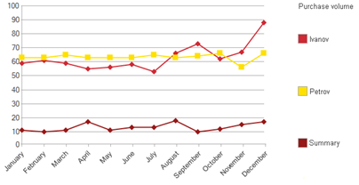
Fig. 248. Summary series
Customizing chart areas
On the whole, the Chart object is intended for operations with charts. To configure the properties of individual chart areas, use its TitleArea, LegendArea, and PlotArea properties, as well as the ShowTitle and ShowLegend properties.
The properties of the ChartPlotArea object allow you to customize the display of the chart scale, data table, and output values. To format the title area and legend area, use the properties of ChartTitleArea and ChartLegendArea objects.
For example, you can specify the value scale format as follows:
Chart.PlotArea.ValueScaleFormat
= "NFD=2; NDS=.; NGS=' '; NG=3,0";You can configure the value scale format and other properties using the plot area property palette:
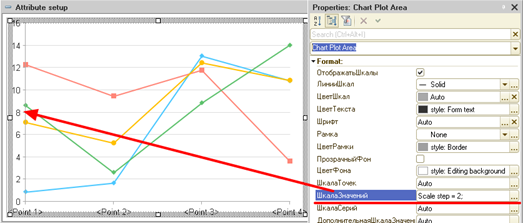
Fig. 249. Plot area properties
Spline mode
The method of plotting the connecting line of the graph depends on the values of the SplineMode and SplineStrain properties.
By default, values in the chart plot area are connected by straight lines. In the SmoothCurve spline mode, "smooth curves" are used to connect values.
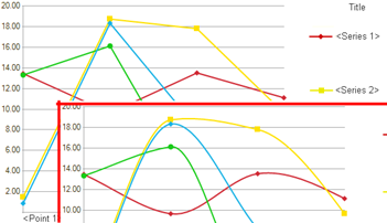
Fig. 250. Spline
At the top of fig. 250, there is a chart with the spline mode disabled, whereas in the lower part, the spline mode is enabled, with the standard spline strain.
Trendlines
You can add a trendline to a series as follows:
Series = Chart.Series.Add();
TrendLine = Series.TrendLines.Add();
TrendLine.ApproximationType
= ChartTrendlineApproximationType.Exponential;
TrendLine.Marker = ChartMarkerType.None;To add a trendline, use the special ChartTrendline object. For a single series, you can create multiple trendlines at once.
You can specify the following parameters for a trendline:
-
Trendline color (the Color property).
-
Whether the trendline should be displayed in the chart legend (the ShowInLegend property).
-
Whether the actual equation used to plot the trendline should be displayed (the ShowEquation property).
-
Configure the equation display mode if it is displayed (the EquationArea property) and so on.
For details on editing trendlines, see Trendlines.
Setting semitransparency
For certain types of charts, use the SemitransparencyMode and SemitransparencyPercent properties to adjust the mode and degree of the chart transparency.
If the SemitransparencyMode chart property is set to the Use mode, then the chart transparency is specified by the value of the SemitransparencyPercent property. If the semitransparency percent is set to zero, then the default transparency percent for this type of chart is used.
In the Auto mode, transparency is automatically set based on the value of the SemitransparencyPercent property, chart type, and other factors.
Using a single color for a series
When you create several charts that use the same series (for example, different charts related to sales), it is advisable to use the same color for a single object in all charts. Thus, a chart is better perceived by its users.
Reports generated using the data composition system support this by default. If a chart is based on a form, you need to perform certain extra operations. Let's have a closer look at these operations.
The platform supports the ValueAppearance feature that stores data as to whether the series value and the color used to display the same are consistent. The above object stores consistency data for all kinds of objects involved in generation of charts for the current user. In other words, if the configuration has charts that use warehouses, counterparties, and goods, the ValueAppearance object will store consistency data for all objects mentioned object types. This object stores max 100 most frequently used objects per each value kind (and related colors). So, if an application supports charts where series are related to goods, settings will store color data for maximum 100 goods most frequently used in charts. The ValueAppearance object can be stored in the value storage. The data composition system uses the Common/ChartColors setting for this.
The scheme of operation is as follows:
-
The chart is filled in with respective data.
-
Information on how objects and colors are related is retrieved from the storage. For example, you can use the system value storage: SeriesColors = SystemSettingsStorage.Load("Common/ChartColors";.
-
The result is loaded into a chart: Chart.FillSeriesColors(SeriesColors);. Colors will be filled in for series with the Auto value set.
If a color from the current palette, which is already used in this chart, is obtained during the filling of the series of colors from the saved colors, then it will be replaced with a lighter or darker color (depending on the color itself and other colors already used). The resulting color will be used for series. If color conflicts occur for the next series, the color is again replaced with a lighter or darker one, taking into account the previous colors.
- After that, it is recommended that you save color matching data to the storage again: SystemSettingsStorage.Save("Common/ChartColors", , SeriesColors);. It is recommended that you save data upon generation of a chart, since it can have objects that have not yet been involved in the chart generation process. Thus, the chart assigns another color to a new object by default. Make sure that you save this data in the storage for further use.
If a form enables you to modify the chart series color, it is recommended that you do this as follows:
-
Get color and ValueAppearance object consistency data.
-
Assign a color to a series using the ChartSeries.Color property.
-
Edit the color in the color and object consistency data set using the ValueAppearance.Set(Object,Color) method.
-
Save color and object consistency data in the storage.
Event handling
For the chart field, event handling is implemented. The Select event occurs when a chart component is selected. The DetailProcessing event occurs when a chart component is selected, provided that the Details property is set for this component.
With standard processing, the detail value is displayed in a special window. For example, in the Details property of a chart series, a link to the Customers catalog item can be stored:
Series = Chart.Series.Add();
Series.Details = DataTableString.Customer;In this case, a form of the corresponding catalog item will be opened by double-clicking the series name.
There is an option to implement custom "details" for the selected item. For example, to show a list of all sales documents for the selected customer. For this, the DetailProcessing event can be handled, for example, like this:
&AtClient
Procedure ChartDetailProcessing (Item, Details, StandardProcessing)
StandardProcessing = False;
FormParameters = New Structure;
// Transfer the "Customers" catalog item reference
// to the DocumentsByCustomer common form.
FormParameters.Insert("Customer", Details);
OpenForm("CommonForm.DocumentsByCustomer", FormParameters);
EndProcedureSimilarly, you can specify and process details for a chart point or value.
To process the chart selection, use the OnActivate event. To get the selected chart areas, use the GetSelectedItems() method. This method is accessible for the form field extension for the chart field (describes the chart placed in the form) and for the SpreadsheetDocumentDrawing object (describes the chart placed in a spreadsheet document). This method will return an array containing the selected data. The subsequent behavior depends on the application.
&AtClient
Procedure ChartOnActivate(Item)
Data = Item.GetSelectedItems();
EndProcedure7.3.4.3.3. Charting-specific features
Displaying points in stacked charts
In stacked charts, the following algorithm is utilized to determine how each data point will be displayed:
-
Charts supporting the base value:
-
Two sums are calculated for each point: more and less than the base value.
-
Before accumulation, the base value is subtracted from the current value.
-
The resulting value is accumulated by absolute value in the corresponding sum (depending on the sign).
-
-
Charts not supporting the base value:
-
Two sums are calculated for each point: more and less than 0.
-
The current value is accumulated by absolute value in the corresponding sum (depending on the sign).
-
Two chart values are displayed for each point: the cumulative sum of positive and negative values (of the base value or value 0).
This calculation is applied to the following charts:
-
Various types of staked column charts
-
Area charts
-
Stacked area charts
-
Stacked radar charts
-
Stacked radar area charts
Skipping values in charts
Data displayed by a chart may not necessarily contain values in each point of the displayed series. In these cases, it is necessary to control how the chart will display such unspecified (non-numeric) values. To control the display of non-numeric values, use the following chart properties: Nonnumeric values usage and Chart points connection across skipped values option.
The first property specifies how the chart will interpret non-numeric values:
-
As zero. In this case, non-numeric values will be equivalent to 0.
-
Skip. In this case, non-numeric values will be skipped when plotting a chart.
-
Auto. A non-numeric value is considered equivalent to 0.
If non-numeric values will be interpreted by the chart as to be skipped, then using the Chart points connection across skipped values option property, you can set up the chart display mode for such values (this property controls the display of only those charts in which adjacent points in the series are graphically connected to each other):
-
Do not connect. Points between which there are non-numeric values are not connected.
-
Connect. Points between which there are non-numeric values are connected directly.
-
Connect with base. Similar to the Do not connect value. The difference is that a point that has a non-numeric value after (or before) is connected to the base value of the chart but not to another point of the series. Besides, the connection is performed at the same point.
-
Auto. Interpreted as Do not connect.
The display of non-numeric values has a number of features, depending on the chart type:
-
For radar charts, the connection to the base value is interpreted as a connection to the center of the chart.
-
For surface charts, the drawing algorithm is similar to the one described above, but when connecting non-skipped points, 4 adjacent points are considered.
-
For the following chart types, a point that has a non-numeric value is not displayed:
-
Column chart of any kind (without stacking)
-
Stock chart (any). The element is not drawn if at least one of the 4 values used is missing.
-
Isometric chart
-
Gauge chart
-
Bubble chart
-
-
For all normalized and stacked charts, a non-numeric value is interpreted as zero.
7.3.4.3.4. Data for charts
To demonstrate different types of charts, the following data set is used:
| Wholesale buyers | Retail buyers | Dealers | |
|---|---|---|---|
| 14.03 | 6 | 8 | 6 |
| 15.03 | 5 | 9 | 4 |
| 16.03 | 9 | 8 | 6 |
| 17.03 | 5 | 4 | 7 |
Depending on the type of chart, the series can be arranged both in rows and in columns.
If a chart is based on a different data set, this data set is shown directly in the section where the chart is shown. As a rule, in charts (like in the examples below) the Series in rows checkbox is disabled.
7.3.4.3.5. Chart
A chart uses the display method in which the adjacent values within a series are connected by a line.
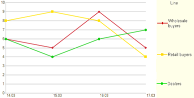
Fig. 251. Graph
7.3.4.3.6. Step chart
A difference between step charts and usual charts is that in the first case the adjacent values are connected by steps instead of straight lines.
It is convenient to use a chart of this kind to emphasize the intermittent nature of change in reference to a value. For example, a change in stock balance at the end of the business day:
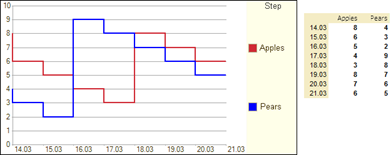
Fig. 252. Step chart
7.3.4.3.7. Stacked chart
A feature of stacked charts is that each displayed value considers the values of the previous series at the same point. They are convenient when you need to evaluate the contribution of each series to the total amount. For example, you can trace a change in the contribution of each group of customers to the total amount of revenue.
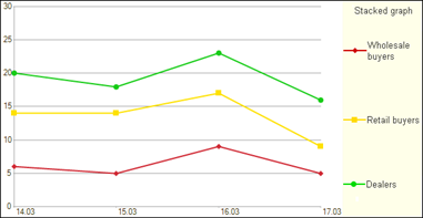
Fig. 253. Stacked chart
7.3.4.3.8. Area chart
An area chart shows an area between the chart line and the base value axis as shaded.
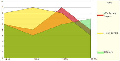
Fig. 254. Area chart
7.3.4.3.9. Stacked area chart
An area chart is similar to a stacked chart. The areas between the chart lines and axis are shaded.
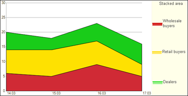
Fig. 255. Stacked area chart
7.3.4.3.10. Normalized area chart
A normalized chart displays the contribution of each series to the total amount of values at a point. For example, at the first point, the series values are 6, 8, and 6. The total amount is 20. The contribution of the first series will be 30%, the contribution of the second series will be 40%, and the contribution of the third series will be 30%.
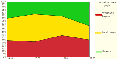
Fig. 256. Normalized area chart
7.3.4.3.11. Column chart, 3D column chart, horizontal column chart, horizontal 3D column chart
Use a column chart to visualize the same data as a graph. However, it uses a different way to display data. Data on the column chart is shown as rectangles, the sizes of which allow you to compare the values of different series at one point.
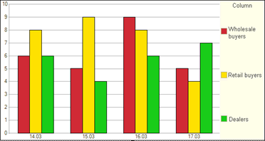
Fig. 257. Column chart
For vertical column charts (regular, stacked, normalized), you can use the 3D chart depth property to change the depth of the chart column.
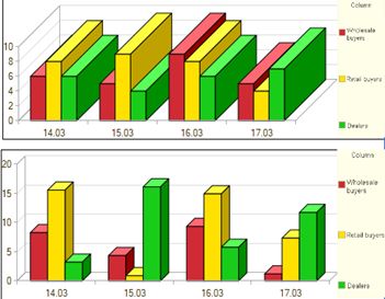
Fig. 258. Different 3D chart depth
fig. 258 shows two completely identical column charts, which differ only in the 3D chart depth property value. The top chart has this property set to 50, and the bottom chart has this property set to 10.
7.3.4.3.12. Stacked column chart, 3D column chart, horizontal column chart, horizontal 3D column chart
A stacked column chart, like a stacked chart (see above), allows you to include the values of all previous series in the value of each series.
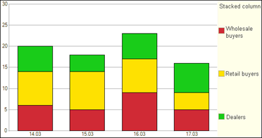
Fig. 259. Stacked column chart
Note that stacked column charts can connect adjacent values within series so that users can easily read the displayed data:
Chart.ValuesBySeriesConnection
= ChartValuesBySeriesConnectionType.EdgesConnection;
Chart.ValuesBySeriesConnectionLines
= New Line(ChartLineType.DottedLine, 2);
Chart.ValuesBySeriesConnectionColor
= WebColors.Red;The resulting chart looks as follows:
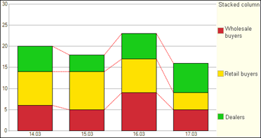
Fig. 260. Stacked column chart with connection of edges
A series of stacked column charts can also be marked using the Indicator property. This series is shown as a chart and is not considered when creating summary series.
7.3.4.3.13. Normalized column chart, 3D column chart, horizontal column chart, horizontal 3D column chart
A normalized column chart, like a normalized chart, displays the contribution of each series to the total amount of values at a point.
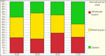
Fig. 261. Normalized column chart
For normalized charts, a combination of values within a series is available.
7.3.4.3.14. Pie chart, pie 3D chart
Use this type of chart to show the share of an individual value in the total amount of values. A pie chart is based on the data of a singular point and a set of series.
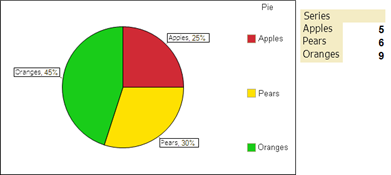
Fig. 262. Pie
If there are multiple points in the pie chart data, then the values of the point specified in the ActivePoint property of the chart will be displayed.
Using the Beginning angle and End angle properties, you can control in which sector of the circle the chart will be generated. For example, if you set the Beginning angle property to 90 and the End angle property to 270, the chart will be displayed in the lower half plane. These properties apply to pie and pie 3D charts.
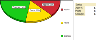
Fig. 263. Display angles are limited
The Beginning angle property determines from which angle (considering the vertical line as 0) the system begins to build a chart. The End angle property determines the angle at which the system finishes building a chart. These two properties define the sector of the full circle within which the system attempts to build a pie chart.
The position of series titles can be set using the Label position property for the Chart object. On fig. 263, the label position is specified as Center.
For a 3D chart, you can use the 3D chart depth property to control the volumetric "width"of the chart.
7.3.4.3.15. Donut charts, 3D donut charts
Like a pie chart, a donut chart shows the share of a separate value in the total amount of values, but it can include more than one point in each series. Each point in a series shown in a donut chart adds a donut to it. The first data point is displayed in the center of the chart.
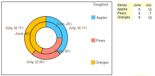
Fig. 264. Donut
To control the inner radius of the donut chart, use the DonutChartInnerRadius chart property.
Similar to a pie chart, the Beginning angle and End angle properties allow you to specify the sector of the full circle that will be used to build a chart. So, on fig. 265, the chart is built in a segment limited by the angle of -135 degrees (the Beginning angle property) and 45 degrees (the End angle property).
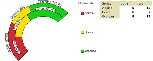
Fig. 265. Display angles are limited
The Beginning angle and End angle properties apply to doughnut and 3D doughnut charts.
Based on the example on fig. 265, we can conclude the following: if the Beginning angle property is greater than 0, the beginning of the chart display is shifted clockwise from the vertical axis. If this property is less than zero, the beginning of the display is shifted counterclockwise from the vertical axis. This conclusion is also valid for a pie chart.
For a 3D chart, you can use the 3D chart depth property to control the volumetric "width"of the chart.
7.3.4.3.16. Stock chart, stock candle chart
Use a stock chart to show four values at one point, which characterize the change in the indicator over a period of time. A set of indicators includes the highest value of the indicator for the period, the lowest value, as well as the maximum and minimum values of the indicator during the period.
A stock chart shows data of a single series. The value of the first point is used as the initial value of the indicator, the value of the second point is used as the minimum value, the value of the third point is used as the maximum value, and the value of the fourth point is used as the value at the end of the period.
Thus, data of the first four points are displayed as a single point of the chart. The name of the first point of a group is used as the name of the merged point. Similarly, the data of the next four points are combined.
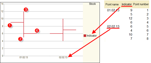
Fig. 266. Stock
A stock chart can contain data of multiple series. In this case, the values of the series specified in the ActiveSeries property of a chart are displayed.
7.3.4.3.17. Bar graph, ceil graph, tape graph, pyramid graph, waterfall
A bar graph is similar to a graph. However, the values within a series are shown as rectangular parallelepipeds of various heights. It allows you to display the dynamics of the indicator broken down by various factors.
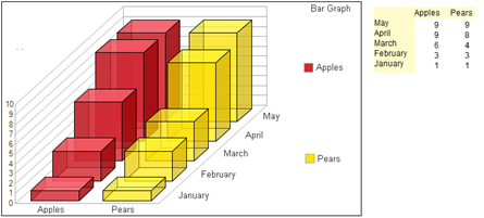
Fig. 267. Bar chart
A pyramid graph shows values as pyramids of various heights. A tape graph displays the change in series values in the form of a tape. A ceil graph is a tape graph with a filled area below the tape. A waterfall is a type of bar chart, in which the series have no thickness.
For charts of the Ceil graph, Tape graph, and Waterfall kinds, you can use the SplineMode and SplineStrain properties.
When the spline mode is disabled for a chart of the Tape graph kind, you can use the Indicator chart series property. A series with the selected Indicator checkbox is displayed semi-transparently, forming intersections with other series.
7.3.4.3.18. Surface, wire-frame surface, convex surface, concave surface, shaded surface, honeycomb
Surface charts make it possible not only to observe the change in the value within the series, but also to trace the dependence of the value on the series at one point.
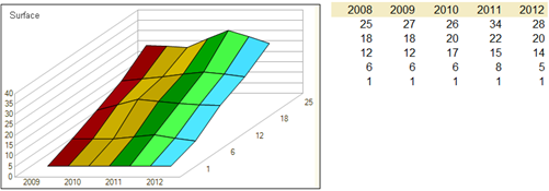
Fig. 268. Surface
7.3.4.3.19. Radar chart, radar area chart, stacked radar chart, stacked radar area chart, normalized radar area chart
A radar chart uses a radar scale to display data. Points are located on a circle. Values are indicated by points located at different distances from the center of the circle.
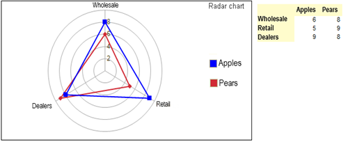
Fig. 269. Radar
The purpose of other types of radar charts is similar to the corresponding cases with a chart of the Chart kind.
7.3.4.3.20. Gauge chart
Gauge charts are formed in the same way as pie charts. A distinctive feature of a gauge chart is in the display of the scale as a gauge panel.
Use the gauge panel to visually attribute the value of the indicator to a specific group.
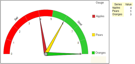
Fig. 270. Gauge chart
To select value ranges, add bands of the gauge panel. A collection of bands is available through the GaugeChartQualityBands property:
Band = Chart.GaugeChartQualityBands.Add();
Band.Beginning = 5;
Band.End = 10;
Band.BackColor = WebColors.Green;
Band.Text = "Good"A gauge chart can display values in two ways: with an arrow or as slices. The required method is specified in the GaugeChartValueRepresentation property. Below is an example of displaying a chart as slices.
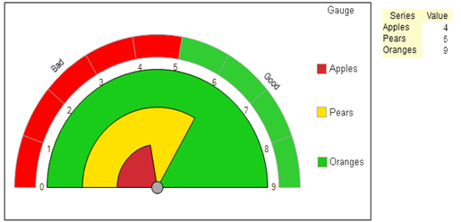
Fig. 271. Gauge chart, by slices
7.3.4.3.21. Funnel, funnel 3D, normalized funnel, normalized funnel 3D
The Funnel chart looks like a horizontal column chart. Values are displayed as segments that form a funnel shape with the corresponding set of data values.
For the Funnel and Funnel 3D charts, their values are displayed by the width of the funnel segment. In the Normalized funnel and Normalized funnel 3D charts, their values are displayed by the height of the funnel segment.
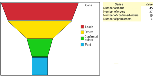
Fig. 272. Sales funnel
Funnel appearance depends on values of the following chart properties: FunnelSpace, FunnelNeckHeight, and FunnelNeckWidth.
For charts of the Funnel and Funnel 3D kinds, you can use the SplineMode and SplineStrain properties.
7.3.4.3.22. Scatter chart
A scatter chart represents values from different gauges in a single dimension as a collection of points. Most charts have a dimension along one of the axes. However, in a scatter chart, the dimension is represented by points on the chart, while the gauges are on each of the two axes.
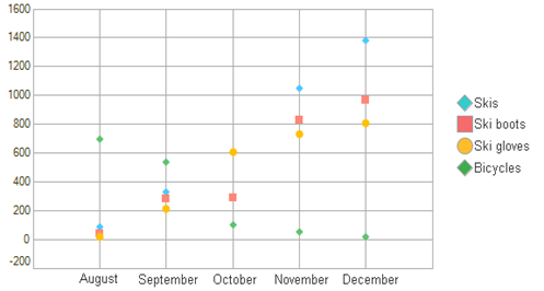
Fig. 273. Scatter chart
This chart is based on the following data set:
| August | September | October | November | December | |
|---|---|---|---|---|---|
| Skis | 90 | 330 | 610 | 1 050 | 1 380 |
| Ski boots | 40 | 280 | 290 | 830 | 970 |
| Ski gloves | 20 | 210 | 610 | 730 | 810 |
| Bicycles | 700 | 540 | 100 | 50 | 20 |
What data to be plotted along the chart axes is determined by the Points axis value source property:
-
Series. In this case, the Points axis series property specifies the series that will be plotted on the point axis.
-
Points. In this case, point values are plotted along the point axis.
-
Auto. In this case:
-
If there is only one series, points are plotted on the point axis.
-
If there are more than one series, the behavior is similar to explicitly specifying the Series value.
-
The example in fig. 273 is displayed with the following settings:
-
The Series in rows checkbox is selected.
-
The Points axis value source property is set to Points.
If you change the chart settings a little, namely:
-
The Points axis value source property is set to Series.
-
The Points axis series property is set to Skis.
-
For the Bicycles series, a trendline has been added, given by the linear equation.
The result will be the following chart:
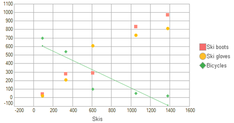
Fig. 274. Scatter chart and trendline
In this case, you can see that the sales of skis and bicycles are inversely related: the more skis are sold, the fewer bicycles are sold. To increase visibility of this conclusion, a trendline has been superimposed on the sales of bicycle.
7.3.4.3.23. Bubble chart
A bubble chart is a type of scatter chart where a point has a variable size rather than a fixed one. Besides, the size of the point (bubble) is the third dimension for such chart. Thus, you can use a bubble chart to display data in three dimensions on a plane.
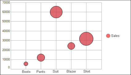
Fig. 275. Bubble chart
This chart is based on the following data set:
| Product | Sales | Market share |
|---|---|---|
| Boots | 5 500 | 3 |
| Pants | 12 200 | 12 |
| Suit | 60 000 | 33 |
| Blazer | 24 400 | 10 |
| Shirt | 32 000 | 42 |
Similar to a scatter chart, to assign data to the chart axis, use the Points axis value source property. In this case, the system logic completely coincides with that for the scatter chart.
For the bubble chart, note the following properties:
-
Bubble size value source. Determines where to get the value that determines the chart bubble size:
-
No. In this case, the chart behavior is completely equivalent to that of the scatter chart.
-
Common series. Indicates the series whose values will be used as the bubble size. To specify a series, use the Common bubble size series property.
-
Next series. In this case, the bubble size will be determined by the series following the series with data. For example, in fig. 275, the bubble size is determined by the Market share column.
-
-
Display of negative values in bubble charts. Determines how the chart will "react" to negative values in data:
-
No (default value). If the value is less than zero, the bubble is not displayed.
-
On module. All values considered based on the module.
-
Transparent background. For calculating the bubble size, all values are used based on the module, but bubbles with values less than zero will not be colored.
-
Inverted background color. In this case, a bubble will be filled with a color that is the inverse of the current series color.
-
-
Bubble sizing. Describes how the value describing the size of a bubble will affect the size:
-
Increase/decrease diameter. In this case, the bubble diameter will change in direct/inverse proportion to the size value.
-
Increase/decrease area. In this case, the bubble area will change in direct/inverse proportion to the size value.
-
In any case, the bubble size will be limited by the Maximum bubble size and Minimum bubble size properties.
-
7.3.4.4. Gantt chart
7.3.4.4.1. General information
The Gantt chart reflects the duration and sequence of processes that are shown as horizontal lines (intervals) placed along the time axis (timescale).
By default, the chart field displays the plot area, the title area, and the legend area. To set up properties and manage area visibility, use the following properties: PlotArea, TitleArea, ShowTitle, LegendArea, and ShowLegend.
In the chart plot area, the timescale is located horizontally, while the points (processes) scale is located vertically. In this section, we will review an example of building an office. The entire process will be divided into three related steps: construction planning, purchasing materials, and clearing the territory.
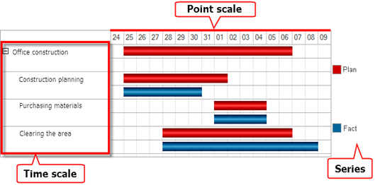
Fig. 276. General information
The Gantt chart shows data as follows:
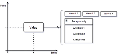
Fig. 277. Gantt chart data structure
The Gantt chart allows you to create several series (the GanttChartSeriesCollection collection). Each series consists of several points (the GanttChartPointCollection collection). If we represent points and series as coordinate axes on a plane (in fig. 277, it is the Points and Series axis), then the Gantt chart value (the GanttChartValue type) will be located at the intersection of a series (the GanttChartSeries type) and a point (the GanttChartPoint type). In the figure, this intersection is shown as a Value rectangle. A chart value is a collection of intervals (the GanttChartInterval type). Besides, a chart value can include a set of additional data (GanttChartValue.Data). Its structure is defined by the application developer depending on the tasks they are working on.
Further, you will learn how to use the Gantt chart.
7.3.4.4.2. Adding data
To manage series and points, use the Series and Points chart properties.
To manage chart values, use the GanttChartValue object. To get the object, use the GetValue() method of the chart object. The value grants you access to the collection of intervals that are displayed in the chart as colorful rectangles. One interval is represented by one rectangle. Consider an example:
// Adding a series.
SeriesPlan = GanttChart.Series.Add();
SeriesPlan.Text = "Plan";
// Adding a point.
PointOfficeConstruction
= GanttChart.Points.Add();
PointOfficeConstruction.Text
= "Office construction ";
// Adding a value.
Value = GanttChart.GetValue(PointOfficeConstruction, SeriesPlan);
// Adding an interval.
Interval = Value.Add();
Interval.Beginning = '20220925';
Interval.End = EndOfDay('20221006');The Gantt chart construed in this way displays a single interval showing the duration of the Office construction process:

Fig. 278. Single interval
Points and series of the Gantt chart can form a hierarchical structure. Example:
// Creating points
PointPlanning = PointOffice Construction.Points.Add();
PointPlanning.Text = "Construction planning";
PointPlanning.Value = "planningConstruction";
PointPurchasing = PointOfficeConstruction.Points. Add();
PointPurchase.Text = "Purchasing materials";
PointPurchase.Value = "purchaseMaterials";
PointClearing = PointOfficeConstruction.Points.Add();
PointClearing.Text = "Clearing the territory";
PointClearing.Value = "clearTerritory";
// Creating intervals
Value = GanttChart.GetValue(PointPlanning, SeriesPlan);
IntervalPlanningPlan = Value.Add();
IntervalPlanningPlan.Beginning
= '20220925';
IntervalPlanningPlan.End
= EndOfDay('20221001');
Value = GanttChart.GetValue(PointPurchase, SeriesPlan);
IntervalPurchasePlan = Value.Add();
IntervalPurchasePlan.Beginning
= '20221002';
IntervalPurchasePlan.End
= EndOfDay('20221004');
Value = GanttChart.GetValue(PointClearing, SeriesPlan);
IntervalClearingPlan = Value.Add();
IntervalClearingPlan.Beginning
= '20220928';
IntervalClearingPlan.End
= EndOfDay('20221006');
// Display setting
GanttChart.ExpandPoint
(Point Construction Office, True);As a result, the chart will show the duration of the three construction stages and the overall construction duration.

Fig. 279. Several intervals
To fill the Gantt chart with data, it is convenient to use the SetPoint() and SetSeries() methods. The SetPoint() (SetSeries()) method returns a point (series) of a chart whose Value property contains a value specified as a method parameter. For example, a reference to a catalog item. If the point (series) with such a key value is not found, then a new point (series) is created and the Value property is filled. You can use the Value property value for a quick search for a point/series. We will use this feature in another example.
Note. Note. The key value of the parent point (series) can be passed to the SetPoint() and SetSeries() methods as the second parameter. If this parameter is not set, a point (series) will be created on the top level of point (series) hierarchy.
7.3.4.4.3. Chart display management
By default, the Gantt chart field displays the chart and a table with the chart data. For how to use Gantt chart data table, see Additional Gantt chart data.
The chart contains horizontal and vertical lines of the layout, including timestamps. To manage how these lines are displayed, you can use the following properties of the form field extension for the Gantt chart:
-
Vertical lines (VerticalLines). Possible values:
-
Yes (True). In this case, all vertical lines are displayed in the chart plot area.
-
No (False). In this case, no vertical lines are displayed in the chart plot area.
-
Auto (Undefined). In this case:
-
Vertical lines are displayed in the area of point texts and the data table.
-
Vertical lines are not displayed in the area of values and intervals.
-
-
-
Horizontal lines (HorizontalLines). Possible values:
-
Yes (True). In this case, all horizontal lines are displayed in the chart plot area.
-
No (False). In this case, no horizontal lines are displayed in the chart plot area.
-
Auto (Undefined). In this case, the Yes (True) value is applied.
-
A text (of a value, a point, an interval) displayed on the chart might not fit into the allocated space (across the width). You can set a text display mode using the Text placement property of the Gantt chart plot area (GanttChartPlotArea.TextPlacement). This property can have the following values:
-
Cut. A text is always displayed in one line. If the whole text does not fit in, it is truncated and adjusted to the display area size.
-
Wrap. A text is displayed in several lines if it does not fit into one line.
-
Auto. The application selects a text placement type. In compatibility mode with version 8.3.22 or earlier, Auto is interpreted as Cut. In other cases, Auto is interpreted as Wrap.
7.3.4.4.4. Specifying timescale settings
The full chart interval is determined automatically by the duration of all displayed intervals if the AutoDetectWholeInterval chart property is set to True. If you disable auto-detection, use the SetWholeInterval() method:
GanttChart.AutoDetectWholeInterval
= False;
GanttChart.SetWholeInterval('20220924', '20221009');A timescale can be supplemented with new levels. For each level, you can specify frequency, period display format, and other properties. Below, you can see how a new timescale level is added to display weekly marks:
WeeklyScale = GanttChart.PlotArea.TimeScale.Items.Insert(0);
WeeklyScale.Unit = TimeScaleUnitType.Week;
WeeklyScale.Repetition
= 1;The chart will look as follows:
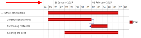
Fig. 280. Weekly timescale
Note that the title of a scale level item is displayed only at the beginning of the respective division. If the beginning of division is not displayed (it turned out to be "to the left" of the displayed range), then the title will not be displayed on the chart.
Labels placeable on the timescale can be accessed through the Labels collection of the timescale item. Remember that the added label will be displayed inside the timescale for which it was added. Let's consider an example of adding a label to the previously added weekly scale:
Label = WeeklyScale.Labels.Add('20221004');
Label.Text = "Control";
Label.LineColor = WebColors.Red;In this case, the chart will look as follows:
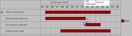
Fig. 281. Label inside scale
If the label is placed this way, data of the selected scale level becomes more difficult to perceive. To avoid it, you can add a fictitious level that will have only nonperiodical labels. In this case, you will add a label for this interval (instead of the previous example):
FictitiousScale = GanttChart.PlotArea.TimeScale.Items.Add();
FictitiousScale.ShowPeriodicalLabels
= False;
Label = FictitiousScale.Labels.Add('20221004');
Label.Text = "Control";
Label.LineColor = WebColors.Red;As a result, the chart will look as follows:
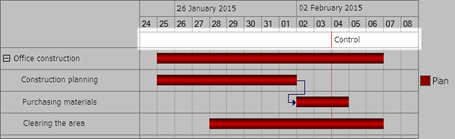
Fig. 282. Label inside scale
Also, you can change colors for the chart fragment background. To do it, add background intervals. For example, you can color holidays:
BackgroundInterval = GanttChart.BackgroundIntervals.Add('20220924', EndOfDay('20220925'));
BackgroundInterval.Color
= WebColors.BlanchedAlmond;
BackgroundInterval = GanttChart.BackgroundIntervals.Add('20220930', EndOfDay('20221001'));
BackgroundInterval.Color
= WebColors.BlanchedAlmond;In this case, the chart will look as follows:
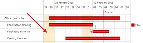
Fig. 283. Selected intervals
7.3.4.4.5. Intervals
The Gantt chart often displays activities (intervals) that last for a certain amount of time and are interrelated. For example, one activity (purchasing materials) begins only after another activity (identifying the demand for materials) ends. To show that activities are interrelated, you can set up dependencies between intervals in the Gantt chart. To do it, add elements to the link collection for the GanttChartInterval object:
Link = IntervalPlanningPlan.Add(IntervalPurchasePlan);As a result, the chart will look as follows:
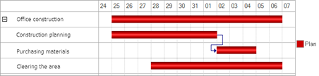
Fig. 284. Interval links
By default, a link is shown as a line from the right bound (end) of the first interval to the left bound (beginning) of the second interval. So, the link type is GanttChartLinkType.EndBegin. If necessary, you can change a link type in the LinkType property of an object with the GanttChartLink type.
Gantt chart intervals can contain notes. A note text is received from the GanttChartInterval.Text property. If the property is not set, the text is received from the GanttChartInterval.Value.Text. To manage the interval text display, you can use the Display interval text (IntervalTextRepresentation) property of the Gantt chart. The property can take the following values:
-
Show. An interval text is displayed.
-
DontShow. An interval text is not displayed.
-
Auto. It is interpreted as DontShow in version 8.3.22 or earlier compatibility mode. In other cases, it is interpreted as Show.
To identify a Gantt chart value or interval, each object contains the ID property that stores an object UUID. IDs are not interchangeable. To get the GanttChartValue or GanttChartInterval object by ID, the GanttChart object has the FindValueByID() and FindIntervalByID() methods.
7.3.4.4.6. Editing a Gantt chart manually
You can change some Gantt chart items and properties both programmatically and interactively. To allow the user to change interval location and size, set the GanttChartValue.Edit property to True.
As an example, let's add the Actual series to the chart data and allow editing its value at the Clearing the territory point:
SeriesFact = GanttChart.Series.Add();
SeriesFact.Text = "Fact";
Value = GanttChart.GetValue(PointOfficeConstruction, SeriesFact);
Interval = Value.Add();
Interval.Beginning = '20220925';
Interval.End = EndOfDay('20221006');
// Interactive interval
editing is allowed. Value = GanttChart.GetValue(PointClearing, SeriesFact);
Value.Editing = True;
Interval = Value.Add();
Interval.Beginning = '20220927';
Interval.End = EndOfDay('20221006');You will be able to edit the actual value in the chart:
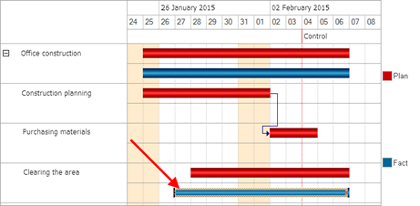
Fig. 285. Interval to be edited
In fig. 285, you can see how to edit an interval interactively.
Besides allowing users to edit specific Gantt chart value(s), you can also manage the possibility of multiple value selection and get the values programmatically. To do it, use the following input field extension properties for the Gantt chart:
-
ValuesSelectionMode. Specifies how Gantt chart values can be selected. Possible values:
-
No. Selection is prohibited.
-
Multiple. Multiple chart values can be selected.
-
Single. Only one chart value can be selected.
-
Auto. Interpreted as No in version 8.3.22 compatibility mode or earlier. In other cases, interpreted as Multiple.
-
-
CurrentValue. Contains the ID of the current selected Gantt chart value. To search for the value that corresponds to the ID, use the FindValueByID() form item method. In the Gantt chart, you can set the current chart value by assigning a new value to the CurrentValue property.
-
SelectedValues. Contains an array of IDs of selected Gantt chart values. Acts the same way as the current value property.
If you enable the Table position property, which displays a data table next to the chart, in the form field extension for Gantt chart, the CurrentRow and SelectionMode properties of the form table with data and the CurrentValue and ValuesSelectionMode Gantt chart properties affect each other as follows:
-
Changing the value of the CurrentRow form table property affects the value of the CurrentValue Gantt chart property and vice versa.
-
Changing the value of the SelectionMode form table property affects the value of the ValuesSelectionMode Gantt chart property and vice versa. In addition:
-
A selection mode set for the form table is also set for the Gantt chart and vice versa.
-
If the value selection mode is disabled in the Gantt chart (GanttChartValuesSelectionMode.No), the GanttChartValuesSelectionMode.Single selection mode is set for the table.
-
If you set the GanttChartValuesSelectionMode.Auto value for the ValuesSelectionMode Gantt chart property in version 8.3.22 compatibility mode or earlier, the TableSelectionMode.SingleRow value is set for the SelectionMode form table property. Otherwise, the form table selection mode is set to TableSelectionMode.MultiRow.
-
Besides selecting values, you can also select Gantt chart intervals. To do it, use the following input field extension properties for the Gantt chart:
-
IntervalsSelectionMode. Specifies how Gantt chart intervals can be selected. Possible values:
-
No. Selection is prohibited.
-
Multiple. Multiple chart intervals can be selected.
-
Single. Only one Gantt chart interval can be selected.
-
Auto. Interpreted as No in version 8.3.22 compatibility mode or earlier. In other cases, interpreted as Multiple.
-
-
CurrentInterval. Contains the ID of the current selected Gantt chart value. To search for the value that corresponds to the ID, use the FindIntervalByID() form item method. In the Gantt chart, you can set the current chart value by assigning a new value to the CurrentInterval property.
-
SelectedIntervals. Contains an array of IDs of selected Gantt chart values. Acts the same way as the current interval property.
7.3.4.4.7. Additional Gantt chart data
Let us get back to our project for office construction. Suppose that you want to see not only time frames of the processes and their relations, but also the cost of each stage in the chart. In this case, you can add a column of the respective type to display the cost and fill it with data. Let us see how you can do it.
In the form editor, create a column for an attribute of the GanttChart type. Create a new field for the GanttChart.GanttChartTable form item. Finally, link the form field with the created attribute.
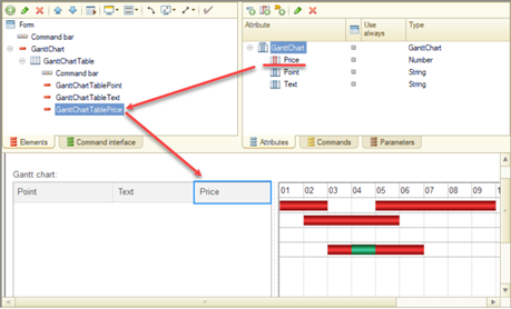
Fig. 286. Adding a data column
In 1C:Enterprise language, this sequence of actions will look as follows:
// Add a data column to
form attributes
CostType = New TypeDescription("Number", New NumberQualifiers(15, 2, AllowedSign.Nonnegative));
NewAttributes = New Array;
NewAttributes.Add(New FormAttribute("Cost", CostType, "GanttChart", "Cost, USD"));
ChangeAttributes(NewAttributes);
// Add the column to
the form table
CostColumn = Items.Add("GanttChartTableCost", Type("FormField"), Items.GanttChartTable);
CostColumn.Type = FormFieldType.InputField;
CostColumn.DataPath = "GanttChart.Cost";In this example, note that if the Gantt chart is a form attribute (as in the current example), add an attribute column by modifying the form attributes rather than using the GanttChart.DataColumns collection. If you create a Gantt chart in 1C:Enterprise language, add columns using the DataColumns collection.
So, you added an attribute to store the cost and a respective column to display data in the form table. Now you need to fill the added attributes with values for all the construction processes. Note that 1C:Enterprise does not automatically process any additional Gantt chart data. In other words, if you need to perform actions with added data (for example, calculate totals by the point/series hierarchy), you have to do it programmatically.
Let us start filling cost values for the construction. Set the following cost values for the planned indicators: construction planning – 200 USD, purchasing materials – 100 USD, and clearing the territory – 150 USD.
// Set cost values for
additional data
TotalCost = 0;
Point = GanttChart.SetPoint("planningConstruction");
Data = GanttChart.GetValue(Point, SeriesPlan).Data;
Data["Cost"]
= 200;
TotalCost = TotalCost + Data["Cost"];
Point = GanttChart.SetPoint("purchaseMaterials");
Data = GanttChart.GetValue(Point, SeriesPlan).Data;
Data["Cost"]
= 100;
TotalCost = TotalCost + Data["Cost"];
Point = GanttChart.SetPoint("clearTerritory");
Data = GanttChart.GetValue(Point, SeriesPlan).Data;
Data["Cost"]
= 150;
TotalCost = TotalCost + Data["Cost"];
// Fill the cost for a
grouping item
GanttChart.GetValue(PointOfficeConstruction, SeriesPlan).Data["Cost"] = TotalCost;Pay attention to the following aspects from the example above:
-
To search for points, use values specified when creating points (the Value property, for details, see Adding data). If you specify unique values (within the chart) in the Value property when creating points/series, the SetPoint()/SetSeries() methods will return required objects without additional actions.
-
The Data collection (of the Gantt chart value) contains all added columns. You can access these columns both by name (as in the example) and by index. If you try to get a value of a column missing in the collection, its value will be Undefined.
-
The TotalCost variable and the last line in the example are used to update the cost of all the construction works. This value consists of the amount of subordinate work costs. If users plan to edit the Cost column in the chart interactively, the developer might need to manually recalculate cost values by the hierarchy.
To identify objects of the GanttChartValue type, you can use the ID property. After you create a Gantt chart value, this property will contain a value of the GanttChartValueID type. The platform will fill it automatically. You can use the ID property value to search for the required value directly using the GanttChart.FindValueByID() method.
Also, note that the GanttChart form attribute has two predefined attribute columns: Point and Text. These columns exist by default and cannot be deleted. These columns refer to the following data:
-
Point: GanttChartPoint.Text.
-
Text: GanttChartValue.Text.
You can manage the data table display both interactively and using 1C:Enterprise language:
-
Interactively. Use the Table position property of a form item of the Form field type of the Gantt chart field kind. The Auto value for this property indicates that the data table must be displayed to the left from the chart.
-
Programmatically. Use the FormField.TableLocation property.
A data table is well suited for situations when an interaction with the chart is required or chart values have additional data. In this case, the chart will have one specific feature: if there are several series, the table will contain like-named rows:
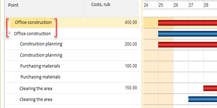
Fig. 287. Table row duplicates
In fig. 287, the chart contains two series: Plan is an upper series and Actual is a lower series. In the Point column of the table, the number of point name recurrences matches the number of series in the chart. An example of one point in different series is enclosed in square brackets. Also, you can see that the cost value is set only for values with the Plan series. Such data display is a feature of the data table display.
If you need to print the Gantt chart in a similar way, you can use the Table position (TableLocation) property of the form field extension for the Gantt chart. If you set the property to No, the chart will look as follows:
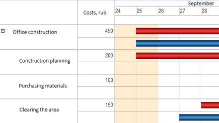
Fig. 288. Print presentation of the table
In fig. 288, you can see that the point presentation combines all the series (you can compare it with fig. 287). The data is still displayed in relation to "its" series. However, such presentation does not allow you to edit the chart data table manually as the table is not shown on the form. Consider converting the chart into a more convenient presentation automatically before printing.
A table with additional Gantt chart data is a standard form table with a number of specific features:
-
The table is always displayed inside the Gantt chart plot area. You can manage the table display using the Table position (TableLocation) property of the Gantt chart field (FormField.TableLocation) form item.
-
The resulting row height is calculated as the maximum of the Gantt chart row height and the table row height.
-
The table header area height and the Gantt chart timescale height are calculated as the maximum of initial heights.
-
The table footer area height and the Gantt chart timescale height are calculated as the maximum of initial heights.
-
When you expand/collapse a table row, you expand/collapse a Gantt chart point.
-
When you expand/collapse a Gantt chart series, you add/delete rows of respective subordinate series.
-
Vertical scrolling of a table and a chart is performed synchronously.
-
Horizontal scrolling of a table and a chart is performed separately.
-
A separator is automatically generated between a table and a chart. It allows you to change the percentage of a visible part for the table and the chart within the overall display area. The separator is generated only if the table with data is displayed in the form.
-
Managing the current row and the data table selection mode depends on the current value/interval of the Gantt chart. For more information, see Editing a Gantt chart manually.
7.3.4.4.8. Event handling
The application calls the OnActivateValue event handler when the user selects a value in the Gantt chart. The event is triggered when the user selects a certain interval or any Gantt chart item. Besides, the event is called when the data table is active and the user selects a row from this table. The event handler allows you to find out for which value the event is called. To do it, use the CurrentValue property of a form item. Note that this property stores the current value ID. To find a value, use the FindValueByID() method. You can also get the selected value using the SelectedValues array of the input field extension for the Gantt chart. This array also stores all selected chart values if multiple selection of Gantt chart values is allowed.
The application calls the OnActivateInterval event handler when the user selects an interval in the Gantt chart. This event handler is called after the OnActivateValue event handler. To get the selected interval, use the CurrentInterval property of the form field extension for the Gantt chart. Note that this property contains an interval ID. To get an interval, use the FindIntervalByID() method of the Gantt chart. You can also get the selected interval using the SelectedIntervals array of the input field extension for the Gantt chart. This array also stores all selected chart intervals if multiple selection of Gantt chart intervals is allowed.
Interactively changing spacings in the Gantt chart would lead to the event OnIntervalEditEnd to emerge. Properties of the modified interval are available in the event handler.
For example, in the event handler it is possible to check the output of the spacing Clearing area beyond full chart spacing and a refusal to edit if a duration of the factual data gets beyond the full spacing:
&AtClient
Procedure GanttChartOnIntervalEditEnd(Item, Interval, CancelEdit)
If Interval.End > GanttChart.EndOfWholeInterval Then
CancelEdit = True;
EndIf;
EndProcedureIf the chart contains hierarchical data (when certain data is subordinate to other data), operations of collapsing and expanding a hierarchy node interactively might require auxiliary actions, for example, read related data. To process collapsing and expanding events, use the BeforeExpand and BeforeCollapse event handlers of the form field extension for the Gantt chart. Each event receives a value ID whose point or series will be expanded or collapsed.
7.3.4.5. Dendrogram
A dendrogram is a graphical way of displaying a degree of similarity of objects. The dendrogram field contains a plot area and a title area. By default, the objects to be compared are listed in the plot area on the horizontal axis, while the difference between the objects is gauged vertically.
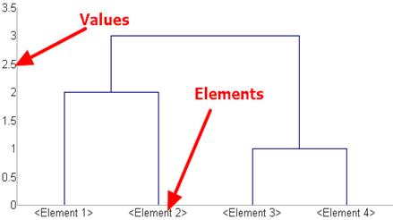
Fig. 289. Dendrogram
The location of the connection line shows the difference in item values.
For example, there are two products with different prices in the dendrogram: apples – 2 USD, pears – 5 USD.
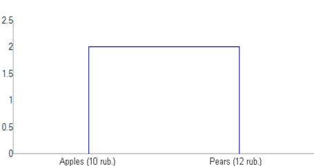
Fig. 290. 2 objects
This dendrogram of 1C:Enterprise language can be construed as follows:
Apples
= Dendrogram.Items.Add();
Apples.Text
= "Apples (2 USD)";
Pears = Dendrogram.Items.Add();
Pears.Text = "Pears (5 USD)"
Link = Dendrogram.Links.Add();
Link.FirstItem = Apples;
Link.SecondItem = Pears;
Connection.Distance = 2;The dendrogram Items collection contains a list of objects. In our case, these are goods. Links between objects are defined in the Links collection.
Now let us add another product to the comparison: Oranges that cost 10 USD. To do this, create one more dendrogram item and one more link:
Oranges = Dendrogram.Items.Add();
Oranges.Text = "Oranges (2 USD)"
Link = Dendrogram.Links.Add();
Link.FirstItem = Apples;
Link.SecondItem = Oranges;
Connection.Distance = 8;The dendrogram will look as follows:
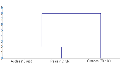
Fig. 291. 3 objects
Note that the arrangement of links corresponds to the order in which they were added. Adding the first link resulted in a grouping of the Apples and Pears items. When you create the second link, the presence of the previously created link is automatically considered, so the second line links the Oranges item with the item formed by linking the Apples and Pears items:
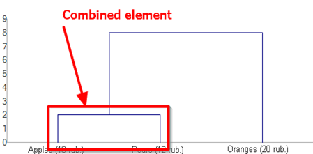
Fig. 292. Merging items
To configure the dendrogram areas, use the TitleArea and PlotArea properties. For example, you can change the value scale format:
Dendrogram.PlotArea.ValueScaleFormat
= "NFD=2;";The dendrogram will look as follows:
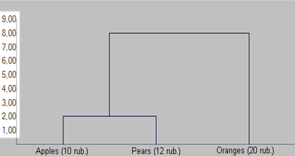
Fig. 293. Value scale format
The mode of automatic adjustment of the dendrogram scale when resizing the form is determined by the ScaleKeeping property:
-
AllItems. All items are displayed in the dendrogram field, regardless of the form size.
-
ItemCount. The visible part of the dendrogram displays the number of items specified in the ScaleItemCount property. Remaining items are available when using the scroll bar.
-
MinimumWidth. When the form size is reduced, the size of the items can be reduced to the width specified in the ItemMinWidth property. If there is not enough space in the visible part to display all the items, a scroll bar is used.
7.4. Form parameters
7.4.1. General information
Form parameters (the Parameters tab) serve two purposes:
-
Describe the data set that will affect opening of the form (parameterization). To do this, list all the necessary parameters and specify their kinds.
-
Determine the parameters that will affect a key of the uniqueness of form. For this, set the Key parameter property for those parameters that should participate in the formation of the form uniqueness key. When trying to open a form, the system searches for an existing form using the previously generated form uniqueness key. If there is a form with the received uniqueness key in the system, then this form is returned. If not, a new form is created.
When calling the form, the values of the parameters created by a developer can be specified in the parameters structure along with the system parameters of forms (if any).
Form parameters can be transferred to a form at the time of its creation. You can analyze the transferred parameters in the OnCreateAtServer() event (the Parameters collection is a property of the ClientApplicationForm object):
// At the place of the
call. // Generate a form
parameter. Parameters = New Structure();
Parameters.Insert("Importance", PredefinedValue("Enumeration.Importance.Important"));
// Open a form with
specified parameters. OpenForm("CommonForm.ReviewForm", Parameters);
…
// In the form module.
&AtServer
Procedure OnCreateAtServer(Cancel, StandardProcessing)
If Parameters.Importance = Enumerations.Importance.Important Then
…
EndIf;
EndProcedureNote. IMPORTANT. After the OnCreateAtServer event handler is called, all non-key form parameters are removed from the Parameters collection.
Note. Tip. Non-key form parameters necessary for further work are to be stored in the form data.
When working with form parameters, keep in mind that the behavior of the parameters can be considered equivalent to the system behavior if the parameter value is not explicitly specified (skipped) when calling the 1C:Enterprise language method. In his case, the parameter value will be set to Undefined (or the default value). The form parameters behave similarly: if the parameter is set when the form is opened in the client application, this parameter will be present in the form parameter structure with a set value. If the parameter is not specified when the form is opened then the platform will automatically add the parameter in the structure of parameters but the value of this parameter will be Undefined. It is equal to skipping the parameter upon the method call. The behavior described above is the same both for the parameters created by the developer and the standard parameters of the form.
7.4.2. Standard form parameters
To support automatic interaction between forms, the system provides a number of standard parameters that are used to manage forms when they are opened. Using these parameters, the system implements a selection in the form fields from the selection forms, opening of object forms, operation of the standard commands, and so on. That is, they provide various scenarios for the operation of interface embedded in the system. However, the developer can also use these parameters in 1C:Enterprise language by passing them when calling the OpenForm() method.
To see the list of the standard form parameters depending on the form extension type, in the built-in help, go to 1C:Enterprise language – Interface (managed) – Managed form – Extension....
7.4.3. Example of working with the form parameters
To demonstrate how the form parameters work, let's consider the implementation of selecting an item in the input field. The essence of this example will be implementation of the mechanism for selecting an item from a list in the 1C:Enterprise language
By the time you start working with this example, you need to have a configuration that has the following properties:
-
There is the Goods catalog containing a hierarchy of groups and items.
-
There is the Analogs catalog with the SelectedGoods attribute of the CatalogRef.Goods type.
-
Both catalogs possess the form items.
Now let's implement in this configuration all the mechanisms that the platform uses to select an item from the list in the 1C:Enterprise language. In this case, we will see:
-
How the standard form parameters are used.
-
How the system uses them.
-
How the developer can use them.
Let's add an additional parameter that will control the selection form closure after an item is selected. Let's call this parameter CloseAfterSelection (the Boolean type). Let's add it as a parameter to the ChoiceForm form in the Goods catalog.
To open the item selection form, in the Analogs catalog item form, create the StartChoice event handler for the SelectedGoods form item.
&AtClient
Procedure SelectedGoodsStartChoice (Item, StandardProcessing)
StandardProcessing = False;
ParameterStructure = New Structure;
ParameterStructure.Insert("ChoiceMode", True);
ParameterStructure.Insert ("ChoiceFoldersAndItems", FoldersAndItemsUse.Items);
ParameterStructure.Insert(AllowRootChoice", False);
ParametersStructure.Insert("CurrentRow", Object.SelectedGoods);
ParameterStructure.Insert("CloseAfterSelection", False);
OpenForm("Catalog.Goods.ChoiceForm", ParametersStructure, Items.SelectedGoods);
EndProcedureIt is necessary to focus separately on the third parameter of the OpenForm() method. This parameter determines who will be the owner of the selection form and who will be notified about the choice made. In this case, we have specified as the owner of a selection form the form item itself but we can also specify by this parameter the form itself. In this case, it will be necessary to implement the ChoiceProcessing event handler of the form module to and decide in it which form attribute to place the selected data in.
Note. Note. If we do not implement the StartChoice event handler, then the system itself will execute its actions. This is true for all further event handlers used in this example.
Now it is necessary to process the transferred parameters in the selection form. Let's do this in the OnCreateAtServer() handler of the selection form module.
&AtServer
Procedure OnCreateAtServer(Cancel, StandardProcessing)
StandardProcessing = False;
Items.List.ChoiceFoldersAndItems = Parameters.ChoiceFoldersAndItems;
Items.List.AllowRootChoice = Parameters.AllowRootChoice;
Items.List.CurrentRow = Parameters.CurrentRow;
CloseOnChoice = Parameters.CloseAfterSelection;
EndProcedureTo check the operability of the form parameters that we set, let's set, using Designer, the ChoiceFoldersAndItems property of the List selection form table to Groups (without using the parameter, the selection of catalog items will not be available).
Note. Note. If the List table that displays a list of goods does not have the ChoiceMode property set to True, goods selection will not be available.
Now we need to process the selection of the required item in the selection form. To do this, there define an event handler for the ValueChoice event of the form table.
&AtClient
Procedure ListSelectionValues(Item, StandardProcessing, Value)
StandardProcessing = False;
NotifyChoice(Value);
EndProcedureIt remains to implement the data processor for the item selection in the input field itself. To do this, process the ChoiceProcessing event of the SelectedGoods input field.
&AtClient
Procedure SelectedGoodsChoiceProcessing(Item, ValueSelected, StandardProcessing)
StandardProcessing = False;
Object.SelectedGoods = ValueSelected;
EndProcedureWe have independently implemented a system mechanism for selecting a value in the input field on the form.
Note. IMPORTANT. This example has not been completed. Its sole purpose is to demonstrate the mechanisms of working with form parameters.
If, when creating parameters (the SelectedGoodsStartChoice() handler), you replace the string:
ChoiceParameters.Insert("CloseAfterSelection", True);with the string:
ChoiceParameters.Add("CloseAfterSelection", False);then the selection form will stop closing after the selection is made. This can be used, for example, to implement a choice form (selecting multiple goods without closing the selection form).
7.5. Form commands
7.5.1. General information
The form actions are performed using form commands. The commands themselves serve only as a description of the actions performed. In order for a command to perform its function, it must be tied to a form item (such as Button) There are several groups of commands that are present in the form:
-
Commands created by developer in the form design process. For them, a handler needs to be created directly in the form module.
-
Standard commands that are provided by the main form attribute extension and extensions of attributes that are lists (for example, an object table, a dynamic list, an information register record set, and so on) if there is a form item associated with this attribute.
Global commands are commands that are provided by the global command interface. Such commands may be both non-parameterized and parameterized. Parameterized global commands will be provided to a form only if there are sources of parameters with the corresponding types on a form.
The availability of standard form commands and the form items is determined by the Command set property of the corresponding form item.
The commands provided by the global command interface (the Global commands tab) can be placed anywhere on the form, just like the form commands.
The Action property specifies a handler that implements the action performed by a command. If a handler is not specified, a command will not be available for use. Only procedures and functions without parameters that are client-side are available for selection in this field (for details, see Form module).
If a command changes the form data, then indicate this by setting the Modifies saved data property. Then, when you try to execute the command:
-
An attempt is made to lock the main form attribute. If the attempt fails, the command will also fail.
-
The Modification checkbox is selected for the form.
If the Modifies saved data property is set for a command and a form is in the View only mode, then all the form items associated with this command will also be in the View only state.
In addition, executing a parameterized global command, for which the parameter is provided by the attribute with the Saved data property set, for a new and unsaved object will result in an attempt to write an object. In this case, the user will be asked if they want to write the object. If the answer is negative, the command will fail.
Note. Note. When you automatically fill in command bars and context menus for which the command source is specified, the standard commands are not added if this item has buttons added manually with the same commands. This logic does not apply to commands added from a fragment of the global command interface.
To simplify development of various dialogs, the commands Yes, No, OK, Cancel, Redo, Stop, Ignore are added to standard form commands. If such a command is added to a form, then when a user clicks this button, the following actions will be performed:
-
For a form opened in modal mode, the form is closed and the corresponding value of the DialogReturnCode type is returned.
-
For a form opened in non-modal mode, only the form is closed.
When forming the name of a command execution handler, the Name property of a command will be used.
Use the standard Help form command to open help information on the configuration form/object. The location of this button on the form command bar is determined by the OnlyInAllActions property of this button. If this property is set to Auto (and for the auto-complete command bar, the actual location will be as follows:
-
Taxi interface. If a form or a parent configuration object has help information, then the button will be located on the command bar. Otherwise, the button will be located only in the More menu.
-
Other interfaces. The button is always located on the command bar form.
Use. For details, see Role-based form customization.
Functional options. Determines which functional options are associated with this form attribute.
7.5.2. Using various commands
For managed form extensions for an object, a catalog, a document, a chart of characteristic types, a business process, a task, and information register record, there is a standard Show in list command. Use it to display the list form of the corresponding object with the positioning of the list being opened on the object from which the command is executed. In the interface, the command will be unavailable if the key attribute of the form is an empty reference (or an empty record key), that is, a new object is being edited.
If the command is used in the document form, then for this command, the Parameter property is available, in which you can select the form that will be used to display a list. A document itself and all journals that include the document used are available for selection. The button associated with the ShowInList command is displayed on a form independently, regardless of whether the Parameter property is full. If the Parameter property value is set, then the default title of the button associated with the ShowInList command is a presentation of a list of the corresponding configuration object (document or journal).
When the document form of the command bar is automatically filled in, the journals containing this document are analyzed, while the current user must have the View access right (see Access rights description) to these journals and the journals must be enabled with the functional options (see Functional options and functional option parameters). If there is at least one such journal, then instead of the Show in list button, there is a group of buttons with the Show in list title in the command bar. The submenu contains:
-
The ShowInList command, for which the Parameter property is filled with a reference to the document in the form of which the command bar is created.
-
The ShowInList commands (one for each relevant journal), for which the Parameter property is filled with a reference to the corresponding document journal.
If there are no available journals, then the command bar contains the ShowInList command, the button of which has the Parameter property not set.
For display, the main form of the list (taking into account the possibility of overriding, for more information, see Redefining the form being opened) of the corresponding configuration object is used.
If it is necessary to provide the functionality of the ShowInList command as part of the implementation of some other algorithm, use the ExecuteNavigation() method that exists for the ClientApplicationForm object.
Implementation example:
Form = OpenForm("Catalog.Counterparties.ListForm");
Form.ExecuteNavigation(Object.Reference);If you need to somehow process the opening of the form with positioning on the required object, use the NavigationProcessing event handler (the event is called for the managed form). If it is required to perform standard actions (the StandardProcessing parameter value is set to True) after executing the NavigationProcessing event handler, then for the first table of the managed form associated with the main form attribute of the DynamicList type (see Working with a dynamic list), the current row is set to the value passed as the Object parameter of the event handler. If the main attribute of the form being opened is not a dynamic list, then no actions will be performed.
7.6. Form module
A form module consists of a set of procedures and functions. Variables and a module body are allowed.
Each procedure, function, or declaration of a form module variable must be preceded by one of the following compilation directives:
- AtClient. Means that a method is executed on the client side and the variable exists for the entire lifetime of the client part of a form.
From the client method, calls to any methods are allowed.
- AtServer. Means that the method is executed on the server side and the variable exists only during a call to execute a server call.
For server methods, calls to server, server out-of-context, and client/server out-of-context methods are allowed.
- AtServerNoContext. Means that the method is executed on the server outside the form context. This compilation directive cannot precede variables.
In such methods, the form context is not available. While calling these methods, form data is not transferred to the server and back. Out-of-context methods can significantly reduce the amount of data transferred when calling a server procedure from the client application environment.
Out-of-context server form methods are allowed to call server methods of common modules.
- AtClientAtServerNoContext. Means that the method is executed both on the client and on the server, outside the form context. This compilation directive cannot precede variables.
Also, this method does not have access to the form module variables.
From a client/server out-of-context method, you can call methods of non-global server common modules and methods of non-global common modules with the Server and Client (managed application) checkboxes.
If there is no compilation directive before the procedure, the default directive is used. The default directive is AtServer
When passing control from the client to the server using the context call, consider one moment. Before starting the call, form data is sent to the server side, the server call is executed after that, and then the form data is sent back to the client. It can take a while. At the same time, an out-of-context server call does not perform such transformations, therefore it is performed faster.
It is not recommended that you keep references to form attributes in module variables (and other available storages) for the duration of operations that may lead to re-creation of the form attributes. These operations include: calling the ChangeAttributes() method when working on the server and executing any context server call when working on the client side.
In the form module (that is, a code snippet placed outside of procedures and functions), it is permissible to use preprocessor commands to explicitly select sections of the initialization code for the corresponding variables.
Note. IMPORTANT. In the server form variable, it is not possible to save data between two calls to the server side of a form.
It is not allowed to use multiple compilation directives before a single method or variable. Methods or variables with the same names that differ only in compilation directives are not allowed.
Developer-created form command handlers can be located only in client methods of the form module.
In the form module, it is recommended that you use preprocessor directives only within procedures and functions.
Note. Note. To understand the result when preprocessor commands "cross" procedure boundaries, take into account that the preprocessor commands are processed before processing compilation directives.
Here is an example of using compilation directives:
&AtServer
Variable
ServerVariable;
&AtClient
Variable
ClientVariable;
&AtServer
Procedure Server()
Message(ServerVariable);
EndProcedure
&AtClient
Procedure Command1Execute()
Message(ClientVariable);
Server();
EndProcedure
#If Server Then
ServerVariable = "Server";
#EndIf
#If AtClient Then
ClientVariable = "Client";
#EndIf7.7. Form items
7.7.1. General information
The visual representation of a managed form is described by a set of items. Form items form a hierarchical collection. The hierarchy of form items determines the appearance and composition of the controls displayed on a form. There are several types of form items:
-
Form, which is a root item of the item tree (see Forms) and exists in a single copy
-
Form field (see Field)
-
Form decoration (see Decoration)
-
Form table (see Tables)
-
Form button (see Buttons)
-
Form group (see Group)
-
Form item add-on (see Supplementing a form item)
Form items of the form field and form table types are always associated with form data. If the associated attribute is not specified, or it is not available on the client due to rights restrictions, or it is excluded from composition (the View and Edit properties of the form attributes), the field will not be visible on the form and will be automatically deleted when the form is created in runtime mode.
Each form item is described by a certain set of properties that determine its behavior on the form, including the display and transformation features, such as changes in the item size when the form or surrounding items are resized (including either disappearance or appearance of items).
7.7.2. General properties of form items
This section describes the general properties of form items. Item-specific properties will be described below.
7.7.2.1. "Main" property group
The Title position property determines how the item title is displayed. The title is a synonym for the form attribute associated with the selected form item, unless the Title property is specified for the form item. The title always ends with ":" (automatically added by the system). Titles of items and groups can dynamically wrap (with automatic increase in the form height) when all the following conditions are met:
-
The title consists of several space-separated words.
-
The item with the title is not:
-
Any item subordinate to the managed form table
-
Menu, button (of the Common button or Command bar button kinds)
-
Page title
-
Group title if it contains additional appearance items (group appearance in version 8.2 interface)
-
If data is displayed in the group title and the above conditions are met, then the text will be wrapped, but the minimum text width cannot be smaller than the size allowed for displaying title data.
When you add an item in the Data property, specify a reference to the form attribute with which this item is associated. If the form item is not associated with the form attribute, then it will not be displayed on a form. If you add a button to a form, then in the Command property, specify a reference to the command that will be executed when the button is clicked. If the button is not associated with the command, then it will not be displayed on the form.
A form item can be in the View only mode (prohibiting any changes) if it has the View only property set (in Designer or using 1C:Enterprise language), or if the group to which it belongs has the View only property set, or if the attribute associated with it has the Saved data property and the form is set to the View only mode.
Visibility of form items is controlled by two properties: Visibility and User visibility. The first property can be changed both in the form editor (in Designer) and programmatically. The User visibility property is configured only in Designer and sets the initial visibility of a form item broken down by roles. The resulting visibility of the form item is formed by adding "by AND" of the Visibility and User visibility properties for a specific user. For a description of editing the User visibility property, see Role-based form customization. In addition, by changing the visibility of form items in the Form settings dialog box, the user actually changes the User visibility property of a particular form item.
Changing the visibility (the Visibility item property) using 1C:Enterprise language, in most cases, does not require a call to the server. However, in the following situations, the server call will still be made:
-
When changing visibility with functional options
-
When changing visibility of the Group item
-
When changing visibility of a managed form table that displays a dynamic list, as well as when changing visibility of columns in such table
For a description of the Height and Width (or the Number of rows) properties, see Rules for placing form items.
With the Skip on input property, you can specify that a form item is skipped when traversing the form using the Enter key. If the property is set to Yes, then an item will be skipped when traversed with the Enter key (but available when traversed with the Tab key or pointing to the item with the mouse). If the property is set to No, then an item will not be skipped when traversed with the Enter key. You can also specify whether to automatically determine the need to skip a form item. To do this, to set the value of this property to Auto. In this case, the following operation algorithm will be used:
-
An item of the Field type will be skipped in case of a view field, a label field, or a picture field, and also depending on the Display warning during editing property value (see Field).
-
An item of the Button type will not be skipped if the button is the default one.
-
An item of the Decoration type will be skipped.
-
An item of the Table kind will not be skipped.
7.7.2.2. Associating items with form attributes
7.7.2.2.1. General information
Any item that displays any data must be associated with a form attribute. There is "normal" connection, when the form item displays the data of any form attribute, and "special" connection modes.
7.7.2.2.2. Connection with a regular form attribute
In the simplest case, the form item displays the value stored in any form attribute. Depending on the attribute type, the system automatically determines which form item will be used to display data and what type this item will be (if possible).
In this case, the Data path property contains the name of the form attribute whose data will be displayed by this item.
7.7.2.2.3. Connection to the current table data
A form item can be associated with an attribute representing a column of a table placed on a form. In this case, this item displays the data fields of the current table row. Such connection is allowed for both fields and tables. It is not required that the corresponding column be displayed in the table. The item associated with the current data can be in either the View only mode or the edit mode.
For example, you need to place a field on the form that displays the price for the current row of goods. To do this, add a field to the desired place in the hierarchy of form items (the type of input field can be either Label field or Input field), for which select (in the Attribute selection dialog box) Object.Goods.Price as data. Here Object is an attribute of a form of the Document kind of specific type, Goods is a document table, and Price is a table attribute.
7.7.2.2.4. Connection to a specific table row
A form item can be associated with an attribute representing a column of the specified table row, which is a form attribute. Such connection is allowed for both fields and tables. It is not required that the corresponding column be displayed in the table. A specific row is specified by a row index (for example, ValueTable[1]) or a sequence of indexes for hierarchical tables (for example, ValueTable[2].TotalsList[4]). An item associated with row data can be in either the View only mode or the edit mode. Please note that such connection is allowed only with form attributes and is not allowed with form items. In other words, the <AttributeName>[Index] expression cannot be replaced with <ItemName>[Index] or <ItemName>.CurrentData.<AttributeName>[Index].
Note. Note. This connection is not supported for dynamic lists.
For example, you need to place a field on the form that displays the value of the Debt field from the 4th row of the Counterparties value table. To do this, we add a field to the desired place in the hierarchy of form items (the input field can be both the Label field and the Input field), for which we select Counterparties[3].Debt (in the Select attribute dialog box) as data. Here Counterparties are a form attribute of the (ValueTable) type and Debt is a value table column.
If field data refers to a missing row, it will not be possible to edit this field, even if the input field is selected. Otherwise, the change made in the input field will be made in the table referenced by the input field.
In the example above, if the user changes the input field, the value from this field will go to the Debt column of the 4th row of the Counterparty value table.
7.7.2.2.5. Connection to attributes through reference
If there are attributes of reference types in form data (for example, CatalogRef), then the form item can be associated with the attribute received by this reference. Data for such items will be received automatically and updated when the reference changes. Connection with attributes through a reference can be of any depth. Items associated with such attributes are always in View only mode.
Note. Note. For attributes of a union type (including such types as CatalogRef, DocumentRef, and so on), it is not possible to receive attributes through a reference.
For example, you need to place on a field on the form that displays the SKU of the current product row. To do this, add a field of the Label field kind to the desired place in the hierarchy of form items. For the field, select (in the Attribute selection dialog box) Object.Goods.Product.SKU. Here Object is a form attribute of the Document type of specific nature, Goods are a document table, Product is a table attribute, and SKU is an attribute for the Goods catalog.
7.7.2.2.6. Connection with collections totals
A form item can be linked to attributes being totals of some collections: tables, record sets, value lists (only the number of rows in the collection). Such attributes can be:
-
Totals by number fields
-
Number of rows per collection
Items associated with such attributes are always in View only mode.
As an example, put on a form the field displaying a sum total for the tabular part Goods). To do this, specify Object.Goods.TotalSum as the form field data, where Object is a main form attribute, Goods are a document table, and TotalSum is a special attribute. Connection can be established not only for the item itself. You can also set a link to display data in the table footer and the tab header (groups of the Page kind).
Depending on the type of data that the form item displays (input field, button, and group), you can use the View property to set how the data is displayed.
7.7.2.3. "Use" property group
For more information on using the Quick choice property, see Quick choice.
For a description of the Choice parameters property, see Choice parameters. If the values of the Choice parameter links and Choice parameters properties are specified both in the properties of the metadata object attribute and in the properties of the form item, then the property values will be merged. A merge will be performed "by OR" (by the parameter names).
You can specify an extended tooltip for the following form items:
-
Field
-
Table
-
Group
-
Button
-
Decoration
To set an extended tooltip, use the Extended tooltip property of the corresponding form item. The ability to specify this tooltip using the Show extended tooltip command from the context menu of the form item is enabled. The extended tooltip is a form decoration of the Text type. To set the extended tooltip text, use the Title property of the decoration. You can control some tooltip display parameters using the properties from the Appearance section of the decoration. If you want to format the tooltip text in a special way, then you need to select the Formatted string radio button value in the extended tooltip editing window. In this case, the advanced design features (like a formatted document) will be available. You can also create tooltips for the form items mentioned above to display them: around the form item, as a button next to the form item, as a pop-up window or set automatic display mode for them. If the tooltip display mode is set to Button, then the Title property of the extended tooltip with formatting will be displayed. If the display mode is set to Pop-up, then the Title property of the extended tooltip will be displayed, but as a regular string with formatting removed). The tooltip button is displayed not immediately after the item text but on the outer side of the right border of this item.
If both the Tooltip and Title properties of the extended tooltip are set at the same time, the text from the extended tooltip will be displayed.
To speed up access to a particular form item, use the Keyboard shortcut property. If a keyboard shortcut is set for some form items, then pressing this keyboard shortcut immediately transfers the input focus to the required item. Keyboard shortcuts do not work for label fields and decorations. However, keep in mind that for some keyboard shortcuts used by 1C:Enterprise, it is impossible to override the executable actions. In other words, if you assign such "reserved" shortcut to perform another action, then when you press the keyboard shortcut, the system action will be executed.
7.7.2.4. "Events" property group
This group contains links to handlers provided by a particular form item.
It should be understood that calling any event handler (not necessarily a form item event) from code in 1C:Enterprise language is not equal to calling the same handler by the platform itself as part of the sequence of events associated with a particular user action. So, for example, a programmatic call to theOnWriteAtServer() event handler of the catalog form module does not mean that a transaction will be opened and a catalog item will be recorded. With such a call, only the handler code will be executed and it is possible that the code will be executed incorrectly or errors might occur during the code execution. Errors can occur because the developer who created this handler proceeded from the fact that this handler would called only by the platform itself and the same platform will provide some environment.
7.7.2.5. Item images
Form items allow you to use images for their design. There are two ways to insert an image:
-
From Designer
-
Programmatically
If an image is inserted programmatically, then either an empty picture or a picture from the Designer picture library can be inserted.
If an image is inserted from Designer, then another option is possible: to set an image from a file on the disk (external image). We recommend that you use such images only in cases where external reports or data processors are developed that can be used in various configurations, and the image is a significant design element. In other cases, the use of such images is undesirable. For form commands and global commands, it is not possible to select an external image.
If you select a file that is an SVG picture with animation (SMIL animation), Designer informs you about this and prompts you to replace the SVG picture with a set of pictures (for more information on a set of pictures, see Common pictures). The set will contain the original SVG image and an animated GIF image specifying that the GIF image must be displayed in Microsoft Internet Explorer and Microsoft Edge (based on the EdgeHTML web page display tool). Designer will get the GIF image automatically. This is because SVG animation is not supported in Microsoft Internet Explorer and Microsoft Edge (based on the EdgeHTML web page display tool). When you convert an SVG animation to a GIF one, keep the following points in mind:
-
You can convert pictures whose animation lasts no longer than 15 seconds.
-
The resulting GIF will not contain more than 30 frames and the frame rate will not exceed 30 frames per second.
-
The conversion result will return a set of two pictures.
7.7.3. Forms
It describes visual properties of a form. An item of this kind always exists in the singular and is at the root of the item hierarchy. Form properties also describe form event handlers.
When you open a form, you can interrupt this process in several places:
-
OnCreateAtServer event handler. Failure to open in this handler will result in the form not being created at all.
-
OnOpen event handler. Failure to open in this handler can lead to various consequences.
If a form is opened so that the resulting object of the ClientApplicationForm kind will not be held in any variable, then the form itself and all data associated with it will be released from memory as a result of failure to open and, in particular, the form wait handlers which could be installed by this time would stop being executed.
If an open form is held in any variable, then a form will be created, all associated data will not be deleted (will remain available for use) and the installed form wait handlers will continue to work. This will retain an ability to try to open the created form again.
To control the form opening mode, use a special property: Window opening mode. This property describes how a window will be opened:
-
Independent. A form opens:
-
Forms in separate windows mode. The form opens in a non-modal window, which is an auxiliary window of the application.
-
Forms in tabs mode. The form opens in a separate tab.
-
Taxi mode. The form opens in the working area of the main application window.
-
-
Lock parent window. The form opens in a non-modal window when work with the form from which the opening of the current form was initiated is blocked. This mode is intended for forms in which little information is entered and work with which does not require a long time. For example, to enter items of catalogs containing a small number of attributes. This mode is externally similar to the modal opening of a form; however, when opening from the 1C:Enterprise language, the operation of the module does not stop for the duration of the opening form. In this case, all other interaction with a form is performed as with other non-modal forms. This form also opens in an auxiliary window.
A form opened in this mode does not participate in the search for already open forms. If you try to open the exact same form (even with the uniqueness parameter set to False), then the form opened in the Lock parent window mode will not be found and a new form will be opened.
This mode is set by default for the following forms:
-
Catalog item and group
-
Exchange plan node
-
Item and group of a chart of characteristic types
-
Account
-
Calculation type
-
Task
-
Record of an independent information register
-
Lock the entire interface. Similar to the form that opens in the Lock parent window mode, but both the parent form and the entire application interface are locked. This opening mode is not used as a default setting.
When a form is opened in blocking mode, the following algorithm for determining the blocking window is used:
-
If a form is set in the FormOwner property and this form is not closed, a window of this form is blocked.
-
If a form item is set in the FormOwner property and this form is not closed, the form window to which this item belongs is blocked.
-
In other cases, if the FormOwner property is set to Undefined or the owner form is closed, the window that is the current window of the client application at the moment of opening the form is locked.
The Window opening mode property does not affect the form opening in the following cases:
-
If it opens in the modal mode. In this case, the form will open modally and in a separate window.
-
When opened in an existing main or auxiliary window. In this case, the form will open in the existing main or auxiliary window.
-
If a form opens from a form blocking the interface. In this case, the WindowOpeningMode parameter of the OpenForm() method will also be ignored. The form will open in a separate window, in the non-blocking mode.
In the Taxi interface, for a form opened in the Lock parent window or Lock the entire interface mode, it is not possible to customize the form navigation panel.
Every form has a title. The title can be set manually, configured automatically, and be combined. If the Title form property is not set and the Automatic title property is set, the form title will be generated automatically (for a description of the rules for generating an automatic title, see Rules of generating standard command texts and automatic form headers). Explicitly specifying the Title property (if the Automatic title property is set) will cause the form title to be generated from the value of the Title property. Then the automatic form title will be displayed via ":". If a form has only the Title property and the Automatic title property is reset, then only the Title property value will be used as the form title.
The Show title property allows you to control the display of the form title (including a flag of the form data modification). You can change the property from 1C:Enterprise language in 1C:Enterprise mode. The property is used only when working in the Taxi interface. If the normal mode of the main window is used, then this property applies only to forms located on the home page of the main window.
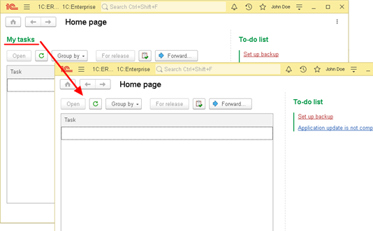
Fig. 294. Title management
If one of the following modes is specified for the main window, the display title property is applied to all managed forms of the application: Workspace, Full-screen workplace, or Kiosk.
The Show Close button property controls whether the form has a close button (if the way the form is opened requires a close button) and the behavior of the ESC key. You can change the property from 1C:Enterprise language in 1C:Enterprise mode. The property is used only when working in the Taxi interface. This property does not control the window close button, which is located in the auxiliary window title.
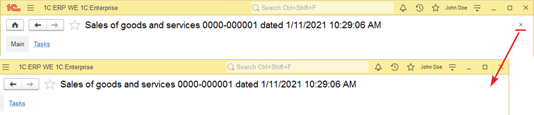
Fig. 295. Controlling the close button
The Show Close button property applies only if the main window is set to one of the following modes: Workspace, Full-screen workplace, or Kiosk.
The Vertical scrolling form property determines the position of the form items on initial display, as well as how the form items behave if the form shrinks vertically:
-
Use value. The vertical scroll bar appears after the vertical size of the form items reaches the size that was specified when editing the form in Designer (this also applies to items with automatic item height determination).
-
UseWithoutStretch value. When the form is stretched, the form items do not react to the resizing of the form.
-
UseIfNecessary value. Before the scroll bar appears, the form items will shrink vertically to their minimum size.
For example, there is a form with the List attribute of the DynamicList type. This attribute is displayed on the form as a List table, for which the height is specified in 8 rows of the table. If the Vertical scrolling form property is set to Use, then the form will hardly shrink:
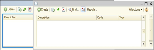
Fig. 296. Vertical form scrolling (use)
In this case, the vertical scroll bar appeared as soon as the form was attempted to be shrunk vertically.
If the Vertical scrolling form property is set to UseIfNecessary, the form will first reduce its vertical size as much as possible, and only then the vertical scroll bar will appear:
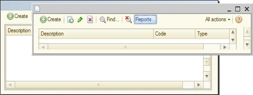
Fig. 297. Vertical form scrolling (use if necessary)
When the property is set to Auto, the form behavior is determined by the system based on the kind of the main form attribute:
-
If the main form attribute is of the DynamicList type or the main form attribute is of the ReportObject type and the ReportResult property is filled in for the report form extension, then the Auto value is interpreted as the UseIfNecessary value.
-
In other cases, the Auto value is interpreted as Use.
In the event that a form has vertical scrolling, then activating any form item that is not entirely represented in the visible area of the form causes the form to try to make the activated item entirely or mostly located in the visible part of the form. This can cause the form to scroll.
The Save window settings property allows you to manage whether to save the form window size and location and the column width of all form tables and separator location. If the checkbox is selected, the specified settings are saved to the system settings storage and restored when the form is opened again. The settings are saved to the /WindowSettings* system settings depending on the client application type. If the checkbox is cleared, the above settings are not saved. If this form already has saved settings, they are ignored when the form is opened but not deleted by the application.
The Scaling mode property determines how the managed form will be displayed in the Taxi interface:
-
Auto. The system automatically determines the form display mode. In this case, the property of the ClientApplicationFormScaleVariant of the ClientSettings object is analyzed. If a specific value of the scaling mode is not specified in this property, then in the Taxi interface, the Auto value will be interpreted as Normal.
-
Normal. The form looks standard for the Taxi interface. The Scale property affects the form size.
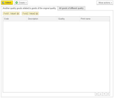
Fig. 298. Normal scale option
- Compact. In this case, the form looks "almost" like in the version 8.2 interface. The Scale property does not affect the form.
Fig. 299. Compact scale option
From a technical point of view, a form that has its Scaling mode property set to Compact has the following features:
-
As the form font, the system font Dialog box and menu font is used.
-
Form items have dimensions that are as close as possible to those in the version 8.2 interface.
-
Distances between the form items are as close as possible to those in the version 8.2 interface.
-
Tables, charts, Gantt charts, dendrograms, graphical schemas, and geographical schemas are displayed without increasing the scale.
This property is intended to simplify the use of complex (saturated) forms in the Taxi interface without processing these forms. This feature is not essential since the resulting interface does not quite match the Taxi interface.
You can also control the scale of all application forms at once. To do this, accordingly set the value of the ClientApplicationFormScaleVariant property of the ClientSettings object. The value of this property will be used for all forms that have the value of the Scaling mod property set to Auto.
If a form is set to the normal display mode, then the form allows you to control the scale of its display using the Scale property. This property indicates what the scale of this form should be relative to its base size (as a percentage). The property value can vary from 10 to 400. If the scale of the entire application is changed in 1C:Enterprise mode (see Application form scaling), then the scale set in the application will be calculated relative to the scale specified using the Scale property. So, setting the form scale to 200% (via the Scale property), the size of a form will be 2 times (for each coordinate) larger in comparison with the base size. If you specify a scale of 50% for such form in 1C:Enterprise mode (using the scale settings dialog box), then the final form scale will be 100%. That is, the form will take on its usual view.
When a list of groups and the catalog contents are displayed on the form at the same time, a task of synchronizing these lists arises so that when a group is selected from the list of groups, the list of items displays contents of the selected group. To facilitate this synchronization, use the Group list form extension property for a dynamic list. This property becomes available if the main form attribute is an attribute of the DynamicList kind. In the Group list property, in this case, specify a table of the managed form that shows a dynamic list that displays only the group hierarchy of the displayed catalog. In this case, the system provides automatic synchronization of lists when navigating through any of them.
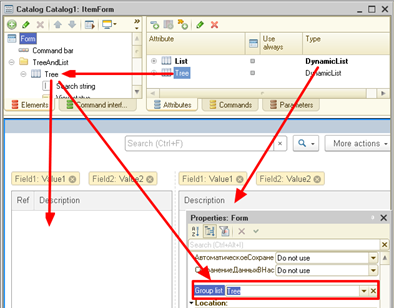
Fig. 300. List of groups
For a form, you can display a command bar (its location on the form can be controlled using the Command bar location property). The set of standard form commands can be adjusted using the Command set form property.
If the Enable form change property is cleared, then the user cannot change the set and relative position of the form items in 1C:Enterprise mode.
The Automatic fill check property is automatically responsible for checking the filling of form data. For more information about filling check, see Operations.
If the Save form data in the settings form property is set to Use list, then the Save column becomes available in the list of attributes. The values of the attributes that have the Save property set to True will be stored in the form data storage. For saving, either the storage specified in the Settings storage form property or the storage specified in the Form data settings storage configuration property will be used.
Note. Note. The Save checkbox is not available for object tables.
To set the View only mode, the form has the ReadOnly property that is available only for programmatic changes. If this property is set to True, then the following standard commands will become unavailable (including when trying to use keyboard shortcuts to invoke these commands):
-
For all forms:
- Restore parameters
-
For table fields:
-
Add
-
Copy
-
Delete
-
-
For object form extensions, information register records, and constants:
-
Save
-
Save and close
-
Post
-
Post and close
-
Clear posting
-
Start
-
Completed
-
-
For extensions of selection forms/settings:
-
Finish editing
-
Select settings
-
-
For table field extensions for a dynamic list:
-
Mark for deletion
-
Post
-
Clear posting
-
Create group
-
Move to group
-
-
For table field extensions for a value list:
-
Change
-
Move up
-
Move down
-
Sort descending
-
Sort ascending
-
Pickup
-
-
All commands for changing the following collections of the data composition system:
-
Collections of settings
-
Collections of available fields
-
-
For table extensions for FormDataCollection, FormDataTree, and FormDataStructureAndCollection:
-
Change
-
Move up
-
Move down
-
Sort descending
-
Sort ascending
-
Also, form items associated with these commands will not be available.
If a form is set to the View only property and the main attribute of a form is a dynamic list, then all the tables associated with this list will also go into view mode. In addition, if the Group list property is filled, then the form item specified in this property will also switch to view mode. In this case, the View only property of form items will not be changed.
7.7.4. Field
7.7.4.1. General information
Use the Field form item to display and edit any form attribute. A form field can be of several kinds:
-
Input field
-
Label field
-
Checkbox field
-
Picture field
-
Radio button field
-
Text document field
-
Spreadsheet document field (for details, see Spreadsheet document field)
-
Calendar field
-
Indicator field
-
Slider field
-
Chart field (for details, see Charts)
-
Gantt chart field (for details, see Gantt chart)
-
Dendrogram field (for details, see Dendrogram)
-
Graphical schema field
-
Geographical schema field
-
HTML document field (for details, see HTML document field)
-
Formatted document field (for details, see Formatted document)
-
Planner field (for details, see Planner)
-
PDF document field (for details, see )
If a field is a subordinate item for the Table form item, then it can take the following kinds:
-
Input field
-
Picture field
-
Label field
-
Checkbox field
To place a form item in the form, create a form attribute of the required type or select an existing form attribute that can be displayed using a form field. Drag this form attribute to the form item tree. The form editor will create a form item of the required type. Another way is to create a form field manually. After that, specify data to display (a form attribute) and a form item type (if necessary) for the created item.
With the Input hint input field property, you can specify a hint that will be generated directly "inside" the input field if the following conditions are met:
-
The associated attribute type is not a Number or Date type.
-
The associated attribute value does not contain the default value for this type.
If the input field displays data of the ValueList kind, then the form for editing the list of values opened from such field receives the following properties from the input field:
-
Mask
-
ChoiceForm
-
EditFormat
-
QuickChoice
-
ChoiceFoldersAndItems
-
ChoiceParameters (supplemented with values, in accordance with the ChoiceParameterLinks property)
-
TypeLink. The type constraint is passed only for the case of editing the data composition selection item. If this property is set for an input field that edits a right-hand value that contains a ValueList, then this type constraint is set to a list of values.
The input field will ignore the BackColor property if the Availability property is set to False for this field or the ReadOnly property is set to True.
7.7.4.2. Updating data to be displayed
When working with an input field, it should be remembered about the peculiarities associated with changes in the form data or its (form) structure while working with data in the input field. The peculiarity lies in the undesirable updating of data in the input field which occurs when the following conditions are met:
-
The input field contains data that is not recorded in the form attribute associated with the input field. For example, when entering text.
-
At this time, an idle handler or an external event handler is triggered.
-
In the event handler, the form data or composition of the form items is modified.
In the described case, the text displayed by the input field will be replaced with the presentation of the data that was received in the form data after the context call was completed. This behavior can be changed in several ways.
Property EditTextUpdate
If in the above situation it is necessary to lock the change of only one (or a small number) of the input field, then such lock can be set using the EditTextUpdate input field property. If this property is set to the OnValueChange, then the contents of the input field will be updated only if a value different from the current attribute value is placed in the associated form attribute. If the EditTextUpdate input field property is set to Never, then the text in the input field will not change even if the value of the associated attribute changes.
Method RefreshDataRepresentation()
If in the scenario described above you need to update only a limited number of fields and leave the remaining fields unchanged, you can use the RefreshDataRepresentation() method. Specify the list of form fields to be updated as a parameter of this method. If the parameter is set, the values will be set and the information displayed will be updated only for the specified field (or list of fields). If a blank array is passed as a parameter, then values will not be set for all the items of the managed form.
Only the following form items can be parameters of this method: FormGroup,FormTable, and FormField.
Using the RefreshDataRepresentation() method makes sense only in the following cases:
-
From an external event handler
-
From a form idle handler
-
From a notification handler
In other event handlers, the behavior does not change: values will be set (and, as a result, the data display will be updated) for all items of the managed form (in web client, only those values that differ from the current form data).
As an example of using this data update method, imagine that data identifying a counterparty is entered in an input field. In the idle handler, the data of this counterparty is checked, and some form items that display the result of the check are changed. In this case, it is recommended that you use the RefreshDataRepresentation() method in the idle handler. Specify the items associated with the check results as a parameter list. The remaining form items will not be updated. Keep in mind that calling a context server call that changes the form data in the idle handler will unambiguously change all form data, except for items with a modified value of the EditTextUpdate property.
7.7.4.3. Data and presentation
Form attribute data can be displayed in a form table and directly by form items. The table can specify only data displayed in the form data and being part of a collection. Generally, a client application form displays a presentation of data placed in the form attribute that is specified as a data source for the form item (up to the form item type). When a form field displays a value of the reference type, it is not recommended that you set the MultiLine property to True. It is recommended that you display values of the reference type in a standard field. To display an object presentation, use other methods, for example, a separate label field.
If data is displayed in the form field and the input field has the List selection mode checkbox selected, the data presentation depends on the selection list. In this case, the form field displays the Presentation column from the selection list, rather than the data presentation (if the said selection list has data currently available in the attribute). If data is displayed in a table, no selection list is used. The presentation in a table cell will always use the data presentation available in the displayed field of the current table row.
This is due to the fact that each table row can have its own selection list. However, the input field for a table row is generated when you start editing. Thus, when a table is displayed, the form is unaware of a proper selection list to be used for value representation purposes.
In view of the foregoing, the following behavior can be observed when data is represented and edited in a table:
-
Data is displayed through its presentation.
-
When you enter the cell edit mode, input field starts to display representation which uses a selection list, provided that input field is assigned list selection mode.
-
As soon as editing is over, data is displayed again through its representation (without regard to a selection list).
There are several scenarios to manage the data presentation in the form table:
-
Use conditional form appearance.
-
To edit the required column, use a separate form input field and specify the current selection list for the same when a table row is changed.
7.7.4.4. Warning during editing
If an attribute is edited in the form input field, which is filled in automatically, but can nevertheless be filled in manually (in extremely rare cases), then this behavior can be implemented using the following input field properties: Display warning during editing and Warning during editing. If the value of the Display warning during editing property is set to Display, then when you try to start editing the 1C:Enterprise field, it will generate a warning that consists either of the line specified in the Warning during editing property or is generated automatically.
For the standard Code and Number fields (for the objects with automatic numbering), the automatic warning line will look like Number is filled in automatically during recording. For other fields, the automatic line will look like Editing the field "Field name" is not recommended. If the value of the Display warning during editing property is set to Auto, then the Display value will be used for the standard Code and Number attributes. For other fields, the Do not display value will be used. The Display warning during editing property also affects the Skip on input input field property. If the value of the Skip on input is set to Auto, then the field will be skipped on input if the value of the Display warning property during editing is set to Display (or Auto for the standard Code and Number fields).
7.7.4.5. Unfilled mark
If the AutoMarkIncomplete property of the input field is set to True, then the property of this field, MarkIncomplete, will be automatically updated when the value is transferred from the attribute to the input field.
7.7.4.6. Displaying radio buttons and checkboxes
If a field of the Radio button field kind is inserted, then for it, set the property of the Choice list form item, which determines the number and values of radio buttons. The horizontal location of radio buttons is used by default. To arrange them vertically, change the value of the Column count property. If the number of columns is set to 0, then the system can arrange the radio button items in several lines, selecting the number of the radio button items per line, based on the free space on the form. Selection is not performed dynamically, rather at the time of form creation.
For the fields of the Checkbox field and Radio button field kinds, you can specify a display kind. For checkbox fields, use the Checkbox type property. Checkbox fields can be represented as segmented buttons, switches, or checkboxes.
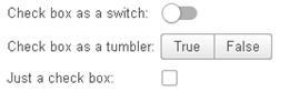
Fig. 301. Checkbox types
In fig. 301, there are various options for displaying a checkbox field. Each checkbox type is described in the title of each line.
The form field of the radio button field type can be represented as a segmented button or a radio button using the Radio button type property.
Fig. 302. Radio button types
In fig. 302, there are various options for displaying a radio button field. At the top of the figure, the radio button field is represented as a segmented button. At the bottom, it is represented as a radio button.
7.7.4.7. Editing standard periods and dates
For a form attribute of the StandardPeriod or StandardBeginningDate type, there are two ways of editing:
-
Using one form field. In this case, you can place a field associated directly with the edited attribute on the form. Then all editing will be performed in this field.
-
Using multiple fields. In this case, you can place fields associated with the attribute properties on the form. In this case, the developer can implement the necessary logic for the interaction between the standard period option and the date values.
7.7.4.8. Context menu of the input field
The input field is the most frequently used item of client application forms. The field provides various options for its management. For example, you can create a unique context menu that is generated in a form editor. However, such context menu has a significant drawback: it remains unchanged, that is, it does not depend on the form field content or any other parameters. To create a managed context menu, use the CommandGenerateProcessing event handler of a form field in the client application. To call the handler, place the cursor in the input field and right-click.
The application provides the handler with the following information:
-
A form item where the context menu will be generated: the Item parameter.
-
An input field area where the context menu creation is initiated: the CommandsParameters parameter.
-
The current context menu content: the Commands parameter. Note that the context menu that is set using the form editor cannot be edited using this event handler.
The Parameters parameter contains the InputFieldCommandGenerateParameters object. The main object property is Source. This property specifies for which input field area the context menu is generated (a value of the InputFieldCommandSource system enumeration type):
-
InputArea. The context menu is generated in a "usual" area of the input field. To be more precise, this is an input field area that does not display a related collection element.
-
MultipleValue. The context menu is generated above an element of a collection related to the input field. In this case, the ID property of the InputFieldCommandGenerateParameters object shows above which collection element the context menu is generated. Note that the received element is not a collection index. To receive an element for which the context menu is generated, use the FindByID() collection method.
In the Commands parameter of the CommandGenerateProcessing event handler, 1C:Enterprise passes the context menu filled by default. This menu includes the InputFieldCommandDescription object array with the following properties:
| Property | Description |
|---|---|
| Availability | Boolean. Defines whether the command is available at the moment. |
| Picture | Picture. Contains a picture to be displayed before the command. |
| Command | Describes the command that will be executed when the user selects this context menu item. You can specify the command using the following methods: · Undefined. Displays a horizontal menu separator. · Value of the InputFieldStandardCommand system enumeration. Allows you to specify a standard input field command. In this case, the other properties of the InputFieldCommandDescription object are ignored, and the display parameters for the standard command are provided by the application. · Value of the CallbackDescription type. Allows you to specify a command implemented in 1C:Enterprise language. · Value of the Array type. A submenu is generated in the context menu. Submenu commands are similar to the context menu commands. |
| Check | Boolean. Allows you to implement a menu item mark. The mark will look like a checkbox and will be located at the left border of the context menu. |
| Presentation | String. Contains a presentation of the context menu command. |
If the input field contains a context menu that is set in the form editor, this menu will be added to the end of the context menu received after closing the CommandGenerateProcessing handler.
Consider an example where default actions are ignored. Instead, a context menu includes the following commands: copy, paste, and clear the input field. Suppose that the field displays a value of the String type, and a form item is called ItemString:
&AtClient
Procedure ItemStringCommandsGenerationProcessing(Item, CommandsParameters, Commands)
Commands.Clear();
Commands.Add(New InputFieldCommandDescription(InputFieldStandardCommand.Copy));
Commands.Add(New InputFieldCommandDescription(InputFieldStandardCommand.Paste));
Commands.Add(New InputFieldCommandDescription(InputFieldStandardCommand.Clear));
EndProcedureNow let us consider an example where a context menu is generated depending on an item on which it is generated:
&AtClient
Procedure AttributeListGenerateCommandsProcessing(Item, CommandsParameters, Commands)
If CommandsParameters.Source = InputFieldCommandSource.MultipleValue Then
CurrentControl =AttributeList.FindByID(CommandsParameters.ID;
// here you can generate a context menu that depends on
// the item value from which the context menu is generated
ElsIf CommandsParameters.Source = InputFieldCommandSource.InputArea Then
// here you can generate a context menu which is generated
// in the input field part where the user enters characters
EndIf;
EndProcedureThe example logic is simple:
-
First, specify where the context menu is generated: in an input area or on an item displayed by the input field.
-
If the context menu is generated for an item, the item is received. After that, you can continue generating the menu based on the item. For example, you can add a report call.
7.7.4.9. Spreadsheet document field
For a managed form field extension for a spreadsheet document, there are the following options for customizing its presentation:
-
Display selection. Allows you to control how selection is displayed in a spreadsheet document:
-
Always. Selection will always be displayed, including if the spreadsheet document field is not active. This value is set by default.
-
When active. Selection will be displayed only if the spreadsheet document field is active.
-
Do not display. Selection will never be displayed.
-
When multiple cells selected. Selection is displayed if it consists of more than one spreadsheet document cell.
-
When multiple cells selected and active. Selection will be displayed if the selection consists of more than one cell and the spreadsheet document field is active.
-
The behavior of the arrow keys in a managed form field extension for a spreadsheet document depends on the value of the Display selection property. When this property is set to Do not display, the arrow keys perform the function of scrolling a spreadsheet document in the direction of the arrows. When the property is set to one of the When multiple ... selected values, then with the Shift key pressed, the arrow keys change the selection size. Without the Shift key pressed, they perform scrolling of a spreadsheet document in the direction of the arrows (without deselecting the area).
-
Vertical scroll bar/Horizontal scroll bar. Allows you to control the presence of scroll bars in a spreadsheet document:
-
Do not use. Scroll bars will not be used.
-
Always use. Scroll bars are always present in a spreadsheet document.
-
Use automatically. Scroll bars are used in a spreadsheet document only when the contents of the spreadsheet document by the corresponding dimension does not fit in the visible area. This value is set by default.
-
-
Pointer type. Allows you to control the appearance of the pointer located above a spreadsheet document:
-
Special. The pointer changes depending on which area of a spreadsheet document the pointer is located. This value is set by default.
-
Standard. The pointer always looks like a standard pointer ("arrow").
-
7.7.4.10. HTML document field
To place an HTML document field on a form, create a form attribute of the String kind, then create an input field of the HTML document field kind, and specify the created attribute as data for this field. The value of the form attribute can be a URL or a text of an HTML document.
To operate with HTML in all operating systems, use WebKit starting from 1C:Enterprise version 8.3.14 (and Version 8.3.14 compatibility mode and later).
Note that using an HTML document field may not support the entire HTML functionality. Keep in mind that web client functionalities can be limited in different web browsers or their versions.
When you use HTML, note the following:
-
HTML document view can vary in different operating systems.
-
Stateful scripts (variables storing values required in various event handlers) are not supported.
-
Operations with SVG markup language (except for displaying pictures) are not supported.
-
The parentWindow HTML document property is not supported.
-
You cannot follow a link inside a displayed page.
-
When accessing DOM model of an HTML document using the HTMLDocumentField.Document property, use only the properties and methods available in all web browsers supported by 1C:Enterprise.
-
If you use an HTML document field to import an external website, note that the website can restrict iframe embedding using X-Frame-Options: DENY. In this case, this website is not displayed in the web client in HTML document field.
7.7.4.11. PDF document field
To display a PDF document in a form, do the following:
-
Create a form attribute of the PDFDocument type.
-
Create a form field of the PDF document field kind. Specify the attribute from the previous step as data.
To operate with a form attribute, use attribute methods. The methods are completely similar to the PDFDocument object methods. The command bar for a PDF document field is created in a standard way.
A form item that displays a PDF document has the URLClick event handler. This handler is called when the user clicks any hyperlink in the displayed PDF document. The developer can analyze the link and decide whether to allow its opening or not.
The UsedFileName allows the developer to specify the full file path in advance. This file will be used to save a file opened in the form field if the user selects file saving commands. With the Save command, the application tries to save the file by the specified path (and name). With the Save as command, the application opens a dialog box to save the file with its previously set name.
See also:
- View state (see Addition for the PDF document field item).
7.7.4.12. Input field list data
7.7.4.12.1. General information
In forms, you can often come across situations when you need to display multiple values from any collection in one field. For example, in a value list or a value table column. Specifically, you might need to display multiple phone numbers, email addresses or something similar in one field. To handle this situation, you can place a table on the form. This table will display collection values. However, this option enlarges the form, especially if you need to place several similar lists on it.
As another option, you can use an input field that displays a value list or a value table column. In this case, values of the collection related to the form field are displayed inside the input field. You can also add values to the collection and delete them using the input field. With this option, the collection height does not occupy a lot of form space, but it might require a wider input field. Below in this guide, this option will be referred to as an input field in multiple value selection mode.
In the figure below, you can see a fragment of a form where a list with four values is displayed using both of the above methods:

Fig. 303. Comparing value list views
In the figure, both form items have the same width, and the list table height is limited by the image height.
The figure shows that the input field allows you to:
-
Enter new values. You can see the cursor after the fourth item.
-
Delete existing values. Each item in the input field has a cross icon.
-
Select multiple values. The first, second, and third items are selected.
-
Use standard input field buttons.
The input field can display only multiple values or enter multiple values in addition to displaying them. To enable the input field to display multiple values, input field data must be a value list or a form attribute of the FormDataCollection type. To manage whether multiple values can be edited in the input field, use the Extended editing of multiple values (MultipleValuesExtendedEdit) property of the form item. If the property is enabled, you can edit values in the input field. If the property is disabled, you cannot edit values in the input field. For this purpose, a separate editing form will open. Note that you cannot manage how the form field will display such data.
If multiple values do not fit into a data area of the input field with full presentations, the following happens:
-
Value presentations are shortened by standard rules when an ellipsis (...) is added at the end.
-
If the shortened presentations also do not fit into the data area, the input field contains the shortened presentations that completely fit into the data area with the +N button, where N is the number of hidden items.
The field behavior depends on the height set for this field in the form:
-
The field height is equal to one line:
-
Multiple values are placed at the beginning of the data area. A text begins to the right of the last item.
-
The text editing area can shrink up to the minimum width in three characters.
-
If multiple values do not completely fit in, the +N button appears.
-
-
The input field height is equal to two lines:
-
The bottom line is always used to enter a text.
-
The top line displays multiple values.
-
If multiple values do not completely fit in, the +N button appears.
-
-
The input field height is more than two lines:
-
The bottom line is always used to enter a text.
-
Top lines display multiple values.
-
If multiple values do not completely fit in, the +N button appears.
-
If the user click s + N, all values that did not fit into the input field will be shown. To display the hidden values, the input field size will change. After the action is performed, the size will be reset to the initial one.
Consider the differences in the behavior of the input field that displays multiple values depending on the Extended editing of multiple values property state:
-
The property is enabled:
-
By default, for new input fields.
-
You can edit data in the input field.
-
-
The property is disabled:
-
By default, if a form field was created in previous versions.
-
You cannot edit or delete values in the input field.
-
You can select multiple values and copy their presentations to clipboard.
-
You cannot use multiple value hyperlinks or open values by clicking hyperlinks.
-
You cannot use input field properties related to editing multiple values, including inside the dialog box to edit multiple values:
-
MultipleValuesHyperlink
-
AllowInputEmptyMultipleValues
-
AllowMultipleValuesDuplicates
-
ShowCheckBoxesInDropListWhenInputMultipleValues
-
-
You cannot use input field events related to editing multiple values:
-
MultipleValuesAdd
-
MultipleValuesDelete
-
MultipleValueOpening
-
MultipleValueURLProcessing
-
-
To apply appearance to multiple values both in display mode and input mode, use the following properties and features:
-
The MultipleValuesBackColor property
-
The MultipleValuesTextColor property
-
The MultipleValuesFont property
-
The MultipleValuePictureSize property
-
The MultipleValuePictureShape property
-
Conditional appearance of the form for multiple values.
Whether you can add values to the input field depends on extended editing of multiple values in the input field. If extended editing is disabled, you can add values only in the form for editing a value list, in the custom form for editing a data collection (displayed by the input field), or using 1C:Enterprise language. If extended editing is enabled, you can enter new values, view the list with checkboxes, use multiple selection in the form, and apply other extended editing features.
We recommend that you use the input field in multiple value edit mode to enter uniform data, such as:
-
Email addresses
-
Phone numbers of users or counterparties
-
Edit the filter by the list in the data composition system
-
Set categories, multiple characteristics, tags, and so on
-
User roles
Let us take a closer look at how you can set up the input field to display and use a value list or a form data collection.
7.7.4.12.2. Simple input field setup
To enable the input field to display list data in multiple value selection mode, place the input field on the form and specify an attribute of the ValueList or FormDataCollection type as a data field. In the first case, no additional actions are required. The field will immediately display all the necessary information. The list values will be displayed by respective presentations. In other words, the input field will display the Presentation property content for each value list item.
So, if the displayed list is filled as follows (List is a form attribute of the ValueList type):
List.Add(1, "First
item");
List.Add(2, "Second item");
List.Add(3, "Third
item");
List.Add(4, "Fourth item");Then the input field will look as follows:
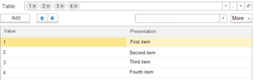
Fig. 304. Value list display
If FormDataCollection is displayed, fill the following properties:
-
MultipleValueValueDataPath. Specifies a column that stores values shown in the input field. If you specify only this property, the input field will display value presentations (a result of the String() function for each displayed value). If you do not fill this property, the field will not be displayed on the form.
-
MultipleValuePresentationDataPath. Specify this property only when a data presentation differs from a presentation of a respective default value.
Suppose that a form contains the Table attribute with the (ValueTable) (FormDataCollection) type that is filled with the following data (column headers contain attribute column names):
| TableValue | TablePresentation |
|---|---|
| 1 | First item |
| 2 | Second item |
| 3 | Third item |
| 4 | Fourth item |
If you specify only the MultipleValueValueDataPath property value and Table.TableValue for the input field that displays the attribute, the field will look as follows (the input field is at the top, and the form table is below):
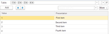
Fig. 305. Table view (without presentations)
If you also fill the MultipleValuePresentationDataPath property for the input field and specify Table.TablePresentation, the input field will look as follows:
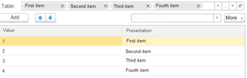
Fig. 306. Table view (with presentations)
In fig. 305, the input field displays values. In fig. 306, the column content is displayed with value presentations. That is the difference between the two input field views.
To be able to edit multiple values in the input field, enable the Extended editing of multiple values property of the input field. After that, to add any value to the list, you can simply enter the value in free space of the input field and press ENTER. To manage input settings, you can use the following properties:
-
AllowInputEmptyMultipleValues. When the input area is empty, it allows you to enter "empty" values into the displayed list by pressing ENTER.
-
AllowMultipleValuesDuplicates. Allows you to enter values that already exist in the displayed collection.
These properties (for empty and duplicate values) also affect the system dialog box for editing value lists. To open the dialog box, click the view button in the input field. However, these properties affect this dialog box only if extended editing of multiple values is enabled for the input field.
Note that the input field in multiple value edit mode has a specific feature. It is related to a value type. The input field might contain two value types: a type of a form attribute value displayed by the field and a type of a data column value used as a multiple value source. A column value type is a value of the Value type property for the ValueList form attribute and a type of the column specified as a value of the MultipleValueValueDataPath property of the input field.
If a form attribute type is union (including ValueList or FormDataCollection), the multiple value edit mode is unavailable in the input field. If a data column that is a multiple value source has a union type, the edit mode is available. However, in this case, press F4 to activate the type for the value you enter and then enter the multiple value. Do it for each value. Selecting a type for each value might be ineffective for the user as a value type is known in some input fields and does not have to or cannot be changed. In this case, the user can restrict a type for the value they enter in a data column. To do it, they can use the TypeRestriction or TypeLink property of the input field.
When using the TypeRestriction property, a multiple value type is defined as an intersection of type descriptions for the following properties:
-
For a value list: attribute types (the Value type property of an attribute with the ValueList type) and types that restrict input field types of a client application form using 1C:Enterprise language (the TypeRestriction property of the input field).
-
For the FormDataCollection type: types of a column specified in the MultipleValueValueDataPath property of the input field and types that restrict input field types of a client application form using 1C:Enterprise language (the TypeRestriction property of the input field).
If an intersection of one of the described type combinations results in a simple type, you do not need to select a type when you enter values.
The TypeLink property of the input field might be useful when a multiple value type is defined by a data attribute and depends on this data. For example, there is an attribute that defines a multiple value type at a certain moment. This attribute must be specified as a value of the TypeLink property of the input field. If a limiting type is simple, the user does not need to select a type every time they want to enter a new multiple value. Note that changing the limiting type leads to the following actions:
-
If input field data contains a single value, it obtains a new type.
-
If input field data contains multiple values, they remain unchanged.
The ChoiceParameters property of the input field is similar to a standard input field. However, if choice parameter values change, the following happens:
-
If input field data contains a single value, it is cleared.
-
If input field data contains multiple values, they remain unchanged.
The ChoiceParameterLinks property of the input field is also similar to a standard input field. If the Edit mode of the linked value property is set to Clear for a parameter, input field data is cleared no matter how many values this data contains.
See also:
-
Choice parameters (see Choice parameters).
-
Choice parameter links (see Choice parameter links).
7.7.4.12.3. Editing data in input fields
The input field in multiple value edit mode allows you to add and delete values in a related collection directly in the input field. Besides, you can open the dialog box for editing related data if the input field displays data of the ValueList type. Let us take a closer look at data editing operations. First, you will find out how to enter new data.
To enter new data, enter the required information in the input field and press ENTER. Make sure the Extended editing of multiple values checkbox is selected. Note that data you enter must correspond to the type of data you edit (for rules on generating the type of value to edit, see Simple input field setup).
When analyzing events that occur when you add or delete values, keep in mind that:
-
If you add multiple values one by one (input by string, checkboxes), each event triggers certain events that occur when a single value is added to the input field.
-
If multiple values are added from the choice form, one set of events is called for all values selected in the form.
When you open the choice form from the input field, the ChoiceByAdding parameter is passed to the form. The parameter allows you to learn an input field mode:
-
True. The input field is in multiple value edit mode, and the form is opened by the platform in the StartChoice handler if the standard choice processing is saved. It is saved when the formal parameter of the StandardProcessing handler is set to True after closing the handler.
-
False. The ChoiceByAdding form parameter is not specified when you open the choice form using 1C:Enterprise language, or the call is performed from the configuration in compatibility mode with Version 8.3.22 or earlier.
-
Undefined. In other cases.
Data entry
Events upon data entry:
-
The EditTextChange event handler is called when the user starts typing a text in the input field. The entered text is passed in the Text parameter of the event handler.
-
AutoComplete. After the text is entered or when clicking the choice button from the list.
-
The StartChoice event handler is called before opening the choice form. To open the choice form, you can click the choice button in the input field, press F4 in the input field, or select the Show all hyperlink in the choice list.
Choice form parameters are passed in the ChoiceData parameter of the StartChoice handler. If the choice form must allow multiple value selection to pass the values to the input field afterwards, pass the MultipleChoice parameter set to True to the choice form.
The ChoiceByAdding parameter specifies how values are selected.
-
False. If extended editing of multiple values is not allowed for the input field.
-
False. If extended editing of multiple values is allowed for the input field. In this case, the handler is called after you click Open in the input field, where the standard event processing is saved in the Open() event handler.
-
True. In other cases.
-
The ChoiceProcessing event handler is called after you select a checkbox in the choice list or select a value in the choice form. The selected value is passed in the ValueSelected parameter. If one value is selected, the parameter contains this value. Selecting values in the choice list using checkboxes is processed in the same way: every time you select a checkbox, it triggers the ChoiceProcessing event. If you add values from the choice form where multiple selection is allowed, the ChoiceProcessing event is added to an array of selected items (in the ValueSelected parameter).
The ChoiceByAdding handler parameter is used to identify how the value is added to the input field:
-
If an event occurs once the NotifyChoice() method is called, the handler parameter value equals the value of the same-name method parameter.
-
If the event is called from a choice form, the parameter value matches the ChoiceByAdding choice form parameter.
-
If the input field supports multiple values, the parameter value is True. Otherwise, False.
-
The MultipleValuesAdd event handler is called before placing a selected value into the attribute related to the input field. For reference types, the event handler has the same features as the ChoiceProcessing event handler. For primitive types, ChoiceProcessing is not called. Therefore, MultipleValuesAdd is the only way to get information on a new value entered into the input field.
-
The OnChange event handler is called if input field data is changed in any way.
The system behavior depends on the selected value and its type. It concerns the arrangement of selected value checkboxes in the event list and event call sequence. Checkboxes are arranged according to the following rules:
-
The ValueSelected parameter contains a single value:
-
The value checkbox is shown if a collection displayed by a field already contains the value.
-
Otherwise, the value checkbox is not shown.
-
-
The ValueSelected parameter contains an array of values:
-
The value checkbox is shown if a collection displayed by an input field contains all array values.
-
The value checkbox is not shown if a collection displayed by an input field contains no array values.
-
The checkbox is in the third state if a collection contains only some array values.
-
Event call depends on whether the checkbox is selected or cleared in the choice list:
-
The checkbox is selected for a single value or a value array:
-
The ChoiceProcessing event handler is called. The ValueSelected parameter contains the value whose checkbox is selected.
-
The MultipleValuesAdd event handler is called. The Values parameter contains the selected value.
-
The OnChange event handler is called.
-
-
The checkbox is cleared for a single value or a value array:
-
The MultipleValuesDelete event handler is called. The IDs parameter contains an array with IDs of values to delete.
-
The OnChange event handler is called.
-
After any change in the checkbox state, the system updates all checkbox states in the input field choice list.
Let us see how the ChoiceByAdding parameter is processed if standard value selection processing is carried out after closing the handler of the ChoiceProcessing input field event:
-
The formal ChoiceByAdding parameter is ignored if:
-
The input field displays a single value that is not a value collection.
-
The input field displays a value collection, but extended multiple value edit mode is disabled.
-
-
In all other cases:
-
The input field displays ValueList. In the event handler, the value of the formal ChoiceValue parameter is of the ValueList type:
-
The formal ChoiceByAdding parameter is set to False:
-
The value of the formal SelectionValue parameter replaces values of the attribute to edit.
-
The OnChange event handler is called.
-
-
The formal ChoiceByAdding parameter is set to True:
-
The MultipleValuesAdd event is called.
-
The value of the formal SelectionValue parameter is converted to the multiple value type and added to the collection.
-
The OnChange event handler is called.
-
-
-
The value of the formal ChoiceValue parameter in the event handler is of the Array type:
-
If the formal ChoiceByAdding parameter is set to False, the current collection is cleared.
-
The MultipleValuesAdd event handler is called.
-
New values are added from the array located in the formal SelectionValue parameter to the displayed collection.
-
The OnChange event handler is called.
-
-
In other cases:
-
If the formal ChoiceByAdding parameter is set to False, the current collection is cleared.
-
The MultipleValuesAdd event handler is called.
-
Content of the formal SelectionValue parameter is added to the displayed collection.
-
The OnChange event handler is called.
-
-
Deleting data
Events that occur when deleting input field values in multiple value edit mode:
-
When clearing the field:
- The Clearing event handler is called once the user sends a field clearing request. To clear a field, use respective input field buttons or press Shift + F4. To cancel field clearing, use the StandardProcessing parameter.
-
When deleting one or multiple items in the input field:
- The MultipleValuesDelete event handler is called. An array with IDs of values to delete from the related value list or collection is passed as the IDs handler parameter. Note that the array contains IDs, not indexes (although, the values are very similar). Unlike an index, an ID does not change when collection items are deleted. To get a collection element by ID, use the FindByID() collection method. Then delete the obtained element. The StandardProcessing parameter allows you to specify that all actions with related data will be performed using 1C:Enterprise language.
-
The OnChange event handler is called after related data is cleared and a form item is updated.
Opening a value form
You can open a value form (if it is available) in a field in multiple value input mode. You can do it in two ways:
-
In the item's context menu, click Open. This item is located in the context menu by default. However, you can also add it to the context menu in the CommandGenerateProcessing event handler (for details, see Context menu of the input field).
-
Click the item if it is displayed as a hyperlink. To manage the feature, use the MultipleValuesHyperlink input field property. Possible values:
-
Yes. Presentation of each multiple value is a hyperlink (it is clickable and underlined when you hover over it).
-
No. Presentation of each multiple value is not a hyperlink.
-
Auto. The system manages the hyperlink display for multiple values. In this case, only reference type values are displayed as hyperlinks.
-
When you click the value hyperlink, the MultipleValueOpening event handler is called. The ID parameter value specifies which item the user wants to open out of all items displayed in the input field.
Programmatic selection
You can get and specify selected values in the input field. For example, if you select several values in an input field in multiple value edit mode, you can use the GetSelectedMultipleValues() form field extension method for the input field to get an element ID array of the displayed collection. To perform the reverse operation (set selection by ID list), use the SetSelectedMultipleValues() method.
To get a collection element ID (a value list or FormDataCollection), use the GetID() method.
7.7.4.12.4. Checkboxes in the drop-down list
If you use a choice list when adding multiple values, you can use checkboxes in this list. So, when a text is entered in an input field, the system selects a set of infobase values that correspond to the entered text and shows the search result in the choice list. A developer can set up the system so that several choice list values can be selected via checkboxes next to each value.
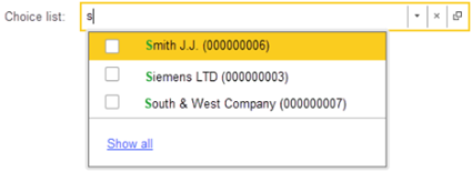
Fig. 307. Checkboxes in the choice list
To manage the availability of checkboxes in the list, use the ShowCheckBoxesInDropListWhenInputMultipleValues input field property. This value has the Boolean type, but it can be set to:
-
True. Checkboxes can be used in the choice list.
-
False. Checkboxes cannot be used in the choice list.
-
Undefined. The value interpretation depends on the value of the AllowMultipleValuesDuplicates input field property:
-
True. Checkboxes are not displayed in the drop-down list. The property is interpreted as False.
-
False. Checkboxes are displayed in the drop-down list. The property is interpreted as True.
-
When you enable or disable a checkbox, you also add or delete an item in the input field. When you change a checkbox state, the choice list is not closed. In this case, events are called in the same way as described above.
If the input field contains selected values, the checkbox display is enabled, and the user clicks the button to open the choice list, the list contains all the selected values with the selected checkboxes. If a checkbox is cleared in the list, all values that correspond to the excluded drop-down list item are deleted from related data.
7.7.4.12.5. Value pictures in the input field
The input field can display pictures for each displayed value. Note that ValueList and FormDataCollection have a different picture display option. These display methods use properties that manage the size and shape of pictures in the input field:
-
The MultipleValuePictureSize property specifies the picture size in the input field:
-
Small. The picture size is equal to 16x16 pixels.
-
Medium. The picture size is equal to 24x24 pixels.
-
Large. The picture size is equal to 32x32 pixels.
-
Auto. It is interpreted as Small in all cases.
-
If the actual picture size differs from the set size, the platform automatically scales the picture.
-
The MultipleValuePictureShape property specifies a picture shape in the input field:
-
Rect. A picture fits into a square.
-
Circle. A picture fits into a circle.
-
Auto. It is interpreted as Rect in all cases.
-
Now let us take a look at how pictures are displayed for the ValueList type. In this case, a picture is received from the respective property of a value list item (ValueListItem.Picture). This is the easiest way to specify a picture.
If you specify picture display parameters as medium size and round shape for the input field, the input field will look as follows (compare: the lower input field shows standard picture display settings):

Fig. 308. Value list. Pictures in the input field
In this case, if a multiple value source is FormDataCollection, the following methods to manage the picture display are available:
-
Place a picture in each collection row (similar to a value list).
-
Specify one picture collection for the input field. In the collection, specify an index of the displayed picture in each collection row.
Let us consider the case where a picture is placed in each collection row. In the input field settings, specify which column will contain pictures. To do it, use the MultipleValuePictureDataPath input field property. After that, add pictures to the column. You can see an example of such code below. The picture is placed in the TablePicture column:
Row = Table.Add();
Row.TableValue = 1;
Row.TablePresentation = "First item";
Row.TablePicture = PictureLib.Constant;
Row = Table.Add();
Row.TableValue = 2;
Row.TablePresentation = "Second item";
Row.TablePicture = PictureLib.Catalog;
Row = Table.Add();
Row.TableValue = 3;
Row.TablePresentation = "Third item";
Row.TablePicture = PictureLib.Document;
Row = Table.Add();
Row.TableValue = 4;
Row.TablePresentation = "Fourth item";
Row.TablePicture = PictureLib.Task;As a result, the input field related to the table in the example will look as follows:

Fig. 309. Value table. Pictures in the input field
Another method to display item pictures in the input field is to specify a set of pictures for all field values using the MultipleValuesPicture property of the input field. In this case, a value in the column specified in the MultipleValuePictureDataPath property will specify an index of the required picture.
If pictures for multiple values are located in a database, you can use the following method for getting pictures to display:
&AtServerNoContext
Function GetEmployeesToAdd(ArrayOfValues)
EmployeesToAdd = New Array;
For Each Ref In ArrayOfValues Do
EmployeePicture = New Structure("Employee,Picture", Ref);
EmployeePicture.Picture = GetURL(Ref, "Photo");
EmployeesToAdd.Add(EmployeePicture);
EndDo;
Return EmployeesToAdd;
EndFunction
&AtClient
Procedure EmployeesAddMultipleValues(Item, ArrayOfValues, StandardProcessing)
StandardProcessing = False;
EmployeesPictures = GetEmployeesToAdd(ArrayOfValues);
For Each EmployeePicture In EmployeesPictures Do
NewEmployee = Employees.Add();
FillPropertyValues(NewEmployee, EmployeePicture);
EndDo;
EndProcedureIn this example, the Employees form attribute is a value list. This attribute is displayed by the Employees input field. Each employee's photo is stored in the Photo attribute of the respective catalog item. When you add employees, a URL to added employees' photos is received. These photos are placed in the Picture property of a value with the ValueListItem type. After that, the input field will display this picture.
When you use pictures in the input field with multiple values, we recommend that you:
-
Do not use pictures received from a file on a disk drive to display items.
-
Use pictures smaller than 128x128 pixels. If the initial picture is larger, we recommend that you change its size using the ProcessingPicture.SetSize() method.
-
You can use any supported method to specify pictures:
-
Specify a URL to an infobase object attribute.
-
Specify a picture address in the temporary storage.
-
Specify a picture index in a picture collection (the MultipleValuesPicture property).
-
7.7.4.12.6. Form table and input field in multiple value edit mode
An input field in multiple value edit mode can be located in a form table. In this case, the operation logic and used tools are similar to an input field located in a form. However, there is one difference that you need to consider when a value type of a table column is a value list. In this case, use 1C:Enterprise language to explicitly set a restriction on an input field type. It will switch the field to multiple selection mode. Consider an example.
Suppose that you have the Employees and AccessRights catalogs. You need to create a form where you can specify access rights for an employee. To do it, create the AccessRightsSettings form attribute with the (ValueTable) type. For this attribute, create two subordinate attributes: Employee (with the CatalogRef.Employees type) and AccessRights (with the ValueList type). Drag the AccessRights attribute on the form. Allow the application to create the necessary columns in the form table.
As a result, you will get the following form:
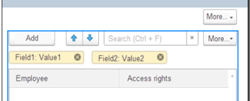
Fig. 310. Example of a field in a table for a value list
As a final step, set a type restriction for an input field that displays a value list. Set the restriction using 1C:Enterprise language as the form editor does not allow you to set a value type for a value list in a subordinate form attribute.
To set the type restriction, specify the OnActivateRow event handler for the AccessRightsSetting form item:
&AtClient
Procedure AccessRightsSettingOnActivateRow(Item)
If Item.CurrentData <> Undefined Then
Item.CurrentData.AccessRights.ValueType = New TypeDescription("CatalogRef.AccessRights");
EndIf;
EndProcedureIf all the actions are performed correctly, access rights will be edited as shown below when you add rows to the AccessRightsSetting table:
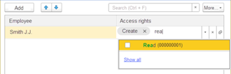
Fig. 311. Editing multiple values in a table
If a multiple value storage in a form table is not a value list but a nested form table, you can set up a form in an easier way:
-
For the AccessRightsSettings.AccessRights attribute, set the (ValueTable) type.
-
For the created value table, create a column with the AccessRight name and the CatalogRef.AccessRights type.
-
Delete the AccessRightsSetting form item and drag the modified AccessRightsSettings attribute on the form. Allow Designer to create all form items.
-
Specify the Multiple value data property for the AccessRightsSettingsAccessRights form item. In this property, specify the AccessRightsSettings.AccessRights.AccessRight attribute.
The form must operate in the same way as in the scenario with a table attribute of the ValueList type.
7.7.4.12.7. Other input field features
Some input field properties influence all the values displayed by the field:
| Property | Behavior description |
|---|---|
| MarkNegatives | Highlights multiple values in red if they are negative. |
| Availability | If field availability is disabled: · The deletion character ("X") is removed from value presentation. · Presentation hyperlinks are disabled. · Selection is unavailable. · Context menu is unavailable. · The standard dialog box for value list editing is inaccessible. |
| Mask | Used to enter text values. |
| PasswordMode | All displayed values are treated as passwords and shown as a fixed string of eight "*" characters. |
| ReadOnly | If a field is in read only mode: · The deletion character ("X") is removed from value presentation. · Presentation hyperlinks are active. · Value deletion is unavailable. · List editing is unavailable when opening the standard dialog box for value list editing. |
| Format | Generates presentation of values of the Number, Date, and Boolean types. |
| TextColor | Used if the MultipleValuesTextColor input field property is set to Auto. |
| Font | Used if the MultipleValuesFont input field property is set to Auto. |
7.7.4.13. Autofilling forms in web browsers or on mobile devices
Mobile devices and web browsers support form autofilling. You can autofill full names, addresses, phone numbers, emails, and so on. In client application forms, the AutoFillHint input field property helps the autofilling feature identify data to suggest for a certain form input field. In web clients or on mobile devices, the value specified in the property is used by the form autofilling feature. In thin clients, the value is ignored. 1C:Enterprise platform supports the following options for input fields:
-
Email. User's email address.
-
City. City name in a user address.
-
Name. User's name.
-
UserName. Username.
-
PostalCode. Postal code in a user address.
-
DontUse. Do not use form autofilling for the field.
-
NewPassword. New password.
-
CreditCardNumber. User's credit card number.
-
PhoneNumber. User's phone number.
-
OneTimeCode. One-time code.
-
MiddleName. User's middle name.
-
Password. Current password.
-
FullName. Full name of a mobile device/web browser user.
-
NamePrefix. User name prefix.
-
Region. Region name in a user address.
-
Country. Country name in a user address.
-
NameSuffix. Username suffix.
-
Street. Street name in a user address.
-
LastName. User's last name.
Here a "user" is a mobile device user (as specified upon device activation) or a web browser user (used for web browser setup) but not a 1C:Enterprise user.
7.7.5. Decoration
It is a design form item. A decoration is not associated with data (form attributes). A decoration can be a label or an image.
A text displayed by a decoration of the Text kind can be dynamically transferred (when a form is compressed or stretched) while the following conditions are met:
-
The text contains several space-separated words.
-
The value of the Stretch horizontally decoration property is not explicitly set to No.
-
The value of the Height property is set to 0.
-
The value of the Stretch vertically decoration property is not explicitly set to No.
The decoration of the Image kind will automatically determine its size (by width and height) according to the set image if the corresponding decoration property (Width or Height, respectively) is set to 0.
Note. Tip. Use decorations only for unchangeable text notes. It is recommended that you display the text that can be changed from 1C:Enterprise language using the field of the Label field kind.
7.7.6. Tables
7.7.6.1. General information
The Table form item is designed to visualize tabular data. This can be a dynamic list, a table, a value list, and so on.
The position of the table command bar is controlled by the Command bar location property of the form item. A set of standard commands located in the command bar of the table is controlled using the Command set property. Commands that are disabled when editing this property become unavailable.
You can group columns using the Group form item. For details, see Grouping and merging form items.
The BorderColor and Border properties set for the table column do not affect the column display.
For a form attribute of the ValueList kind, you can choose how the attribute will be displayed. If the Table option is selected, the value list will look like a table with the following available columns: Value, Presentation, Check, and Picture. Remember about the features of displaying values in theValue column. This column will display the value of the Presentation column. The value itself remains unchanged. If the Input field kind is selected, a special window will be opened for editing the list.
Also, a standard set of editing commands including setting and unmarking commands, is provided for the table associated with the ValueList kind attribute.
If in a vertical group of columns in a certain row the width of columns exceeds the width of columns from other rows, then in the narrower rows the last column of a group stretches to the width of the widest row. Stretching is performed even if for this column has the Stretch horizontally property set to False. If column stretching is to be avoided, then that column should be moved out of the group to be stretched and be placed separately.
7.7.6.2. Dynamic list display
When a form with a dynamic list is opened, data is read only for visible tables associated with dynamic lists. For the tables that are not visible when a form is opened, the data is read at the time they (tables) are displayed to a user. In particular, for invisible tables, the value of the CurrentRow property will be set to Undefined. This particularity should be considered when developing a form logic.
Note. Note. If a table displays a dynamic list (see Dynamic list) and the Initial tree display property is set to Expand all levels, then when a form is created on the server, then only a list of rows displayed at the first level will be retrieved, and then, when the form is opened, the rest displayed rows will be retrieved. For each displayed group, a separate request to server will be executed.
If a table is associated with an attribute of the DynamicList type that has grouping set in the list settings (the List settings form attribute property), then the list will always be displayed in the Tree mode (the Display form item property) no matter which display mode is set by the developer. If the View only property is set for the table associated with the dynamic list, when objects are opened from such list of object forms, they will automatically be set to the ReadOnly form parameter.
Also, for a table associated with a dynamic list, you can manage the update of the list when data is changed (in the same client application) using the Update when data is changed property. If the property is set to Auto, then the list will be updated automatically on any changes in the displayed data. If the property is set to Do not update, then the list will not be updated automatically. To update it, explicitly execute the Update() command. If a dynamic list is set to update automatically at the specified interval and the Update when data is changed property is set to Auto, the interval is counted from the nearest data change. If the value is Do not update, the interval is counted from the last automatic update call or execution of the Update() command.
For a table associated with the main form attribute of a dynamic list type, you can control the multiple selection mode using the corresponding form parameter. The Multiselect form parameter value will be set to the table property of the same name. In this case, the Selection mode property will be set to Multiple if the Multiselect form parameter is set to True.
For a dynamic list in the selection mode, when adding a new object, a check will be performed to ensure that the added object meets the specified selection criteria. If the new object meets the selection criteria, the cursor will be pointing to it in the table displaying the dynamic list.
If the list form of a chart of accounts or a catalog with a hierarchy of items opens with the AllowRootChoice parameter set to True and the ChoiceMode parameter set to True, then the following properties will be automatically changed for all tables of the form associated with the main form attribute (such as DynamicList):
-
The ShowRoot property will be set to True.
-
The AllowRootChoice property will be set to True.
-
The Display property will be set to Tree.
7.7.6.3. Image display
A standard row image is formed based on the standard table fields used to determine the item state (DeletionMark, Predefined, and so on). If the query list text includes fields whose aliases match the names of the standard fields, but other data is obtained in them, then such fields will not be used to form a standard image.
If you need to change the standard image:
-
Add the required collection of pictures to the picture library.
-
Select the added image in the RowsPicture property of the table associated with a dynamic list.
-
Add a field that has the image index value to the query text.
Example:
CASE
WHEN Table.DeletionMark THEN 2
WHEN Table.Predefined THEN 1
ELSE 0
END AS PictureIndex- Specify the added field in the RowPictureDataPath property of the table associated with a dynamic list.
The row image will be displayed next to the first (counting from the left) visible field of a dynamic list of the input field or label field kind. If the order of columns changes when you edit table columns, the image will be displayed next to the leftmost column (from the view specified above). However, if the column visibility is disabled using conditional appearance, the system behavior is different. If a column linked to an image (or hierarchy symbol) is hidden, the image (or hierarchy symbol) will not be displayed in this row.
7.7.6.4. Modifying table height
To control the height of the client application form table, use the ItemHeightControlVariant property:
-
In form rows. The table height is set using the Height property of the managed form table. If the value of this property is 0, then the table height will be 16 units for a table displaying a dynamic list and 8 units in all other cases. To limit the maximum height of the form table, AutoMaxHeight and MaxHeight properties are used.
-
In table rows. In this case, the table height is set using the HeightInTableRows property of the managed form table. If the value of this property is 0, then the table height will be 15 rows for a table displaying a dynamic list and 7 rows in all other cases. To limit the maximum height of the table, the AutoMaxHeightInTableRows and MaxHeightInTableRows properties are used.
-
By content. If the table is linked to a dynamic list, the table height is defined by the value of the HeightInTableRows property. If the value of this property is 0, then the table height is determined by the value of the Height property.
If the table is not associated with a dynamic list, then all rows of the table are fully displayed, but at least 3.
If the AutoMaxHeightInTableRows property is set to True, then the table displays no more than 50 rows. If the AutoMaxHeightInTableRows property is set to False, then the number of the rows displayed in the table is limited by the value of the MaxHeightInTableRows property. If the value of the MaxHeightInTableRows to 0, then the table has no limit on the number of rows displayed.
When setting this option of controlling the height of a table, the system ignores a value of the VerticalStretch property and assumes that this property is set to False.
7.7.6.5. Column scrolling
When designing forms, there are situations when it is necessary to prevent certain table columns from scrolling. For example, in the table, you need to dock the Number, Products and Sum columns. In this case, press the Number and Products columns to the left edge of the table, and the Sum column to the right.
To do this, use the FixingInTable property. This property is available for a field located in a table and for a group of the Column group kind (see Group). In this example, for the Number and Products columns, set the FixingInTable property to Left. For the Sum column, set the property to Right. The columns will be pressed to the corresponding edge of the table no matter where these columns were located in the form editor. However, the docked columns are arranged in the order they are placed in the form editor.
If the dock flag is specified for a group, then the entire group will be pressed (along with all subordinate form items), while the value of the FixingInTable property for the subordinate items is ignored. If the dock flag is specified for a column belonging to a group for which the FixingInTable property is set to No, then the column will be treated as a separate column not included in the group.
7.7.6.6. Search in tables
If the table displays data of the DynamicList type, for a description of the search features, see Search in dynamic list.
No search made in a table has impact on the content of FormDataCollection.RowFilter property. The content of the FormDataCollection.RowFilter property cannot be displayed through the View state form item add-on.
The Search when typing property is responsible for how the system will process a character set from keyboard if the active item is a table and the direct data entry into a column is not possible:
-
Auto. In this case, for tables associated with a dynamic list, the property is interpreted as Use, while for tables displaying other types of data, the property is interpreted as Do not use.
-
Use. Search when entering characters is performed for any type of attributes associated with the table if the column in which characters are entered has the Edit mode property set to Enter. The search will use either the search bar if allowed by the Search bar position table property (see Supplementing a form item) or the search form if the search bar is not allowed in the given table.
-
Do not use. No search when typing is made for attributes of all types associated with a table.
The following algorithm is used to search data:
-
The search string is split into words. The search string should not exceed 1,000 characters, and the number of words obtained during splitting should not be more than 20. The splitting is done in compliance with the following rules:
-
The string is split using space and tab characters as separators.
-
Next, each resulting fragment is processed:
-
If a fragment is in the date format (with or without time indication) with regard to the current regional settings of the session, then this fragment is considered to be a single word.
-
Otherwise, the fragment is split further using the characters ",.-//" as separators. In this case, each resulting substring is considered to represent a separate word.
-
-
-
For each word, its own set of conditions for each table column is generated that are combined "by OR". Conditions are generated depending in the column type:
-
String. A word is searched using its initial letters. If a word contains letters and digits:
-
A sequence which contains letters only is deemed a separate word.
-
A sequence which contains digits only is deemed a separate word.
-
-
Number. A word is converted into a number. If the said conversion is not possible, the field search will not be performed. If the conversion is successful, the following condition will be used for the search: FieldValue >= Int(Word) AND FieldValue<(Int(Word)+1). For values with leading zeros, you can perform a search on either the string with leading zeros, or on the string specified without them.
-
Boolean. The word equality with localized value representation of Boolean type is verified (for current session localization language).
-
Date. A word is converted into a date with a month and a year added by default. The field value will be verified for availability thereof in a day defined by the date so obtained FieldValue >= BegOfDay(Word) AND FieldValue<=EndOfDay(Word)).
-
So far as reference fields are concerned, a search will be made using initial letters of a word available in the reference field representation.
-
A set of conditions for each word is combined "by AND".
An element in a table is deemed as found (inter alia, if it has subordinate elements), if at least one of the following conditions is met:
-
It contains all searched words.
-
If has at least one searched word, while the other words are available in its parents, in the first visible column of a string or reference type.
If a column value is modified upon completion of a search attempt with respect to any string, it remains visible, until the searched value is edited, and the search is repeatedly made.
If a table has a predefined search filter, commands intended to move the current table item up and down are disabled for the table.
7.7.6.7. Determining the current table row
When you open a form that contains a table, the current row is determined by analyzing the Initial list view (InitialListView) table property of the client application form:
-
Begin. The first list row will be the current one.
-
End. The last list row will be the current one.
-
Auto. The current list row is determined according to the type of data displayed by the table. Moving to the end of the list will be performed for a table that displays a dynamic list in which the first field in the sort list is the Date or Period field. The dynamic list must process the following data: lists of documents, business processes, and tasks; document journals; records of accounting registers, calculation registers, accumulation registers, and periodic information registers. In other cases, the current row will be the first table row.
If displayed rows in the displayed area change when the table is updated, the behavior depends on no longer displayed rows:
-
If only the current row is no longer displayed, the nearest (by key) list row becomes the current table row and a new list is generated for display starting from it.
-
If all rows in the displayed area are no longer displayed, use the Initial list view (InitialListView) form table property to determine the first row. The behavior is similar to determining the current row when the table is displayed in this form for the first time.
7.7.7. Buttons
On a form, the command is displayed by the Button form item. A button can be displayed in the command bar and just on a form. If displayed on a form, a button can also look like a hyperlink. To do this, change the View property.
A command that will be accessed by pressing a button is set using the Command property. A button will be shown as disabled if the command associated with this button has the Modifies saved data property set to True and the ReadOnly property is set to True for this button or the form as a whole.
If the button associated with the command is located in the command bar, manage its position using the Position in command bar property (LocationInCommandBar):
-
In additional submenu. The button is placed only in the additional More actions submenu.
-
In command bar. The button is placed only in the command bar.
-
In command bar and additional submenu. The button is placed both in the command bar and the More actions menu (if it is available in the command bar).
-
Auto. The position is automatically defined by the system and depends on the command and client application kind.
The command bar has the More menu in the following cases:
-
The command bar contains commands whose placement is set to In additional submenu.
-
Commands whose placement is set to In command bar and additional submenu do not fit in the current command bar.
You can change button placement in the form settings editor. To open the editor, click More actions – Change form in 1C:Enterprise mode.
The Command uniqueness property (CommandUniqueness) is intertwined with the Position in command bar property. In short, this property allows you to place two buttons associated with one standard command in the same autocomplete command bar, but these buttons must be placed in different places of the command bar. The key issues: a) the command bar should be autocompleted and b) it works only for the standard commands. Consider an example.
Let's suppose there is an attribute named Spreadsheet of the SpreadsheetDocument type in the form. This attribute is placed in the form (with the same name) and the command bar (TableCommands), for which the Spreadsheet attribute is selected as the command source, is created in the form. We want to place the Dock the table command in the form command bar and leave it in its default position (More actions – View – Dock table). First, we drag the Fix Table command from the list of standard commands (in the form editor: Commands – Standard commands – TabDoc – Fix Table) to the TableCommands command panel. As a result, the command will appear only in the More menu (this is the standard placement for this command) and will be removed from its default placement. We are not satisfied with it. Therefore, we point to the SpreadsheetFixTable button in the form editor and set the following properties:
-
The In command bar value for the Position in command bar property. Now the required command has turned out to be visible at once and has disappeared from the More menu.
-
Clear the Command uniqueness property. As a result, the command has reappeared in the same place in the menu where it was located by default.
The form will look as in the figure.
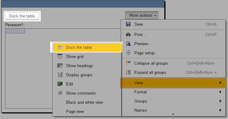
Fig. 312. Command uniqueness for the form button
For the button associated with the Generate by parameter command, you can specify the type of a document that will be created when the button is clicked. To do this, use the Parameter button property.
If the Tooltip property is not set for the form command, then the button associated with this command will not display a tooltip. If the button title cannot be fully displayed on the button, then the full text of the title is displayed in the tooltip as the first (or the only one if no tooltip is set for the button) line.
A button can have several display modes (the Display property). If the Image and text display is selected, then the image located on a button can be located on the left or right relative to the button text. To control this position, use the Picture position button property (available for form and command bar buttons). If this property is set to Auto, then an image will be located on the left side of a text.

Fig. 313. Button image position
If the Image display is selected for a button, the image will always be located in the center of the button.
A managed form button can be displayed in various ways. For this, use the Button shape button property.

Fig. 314. Button shape
This property can have the following values:
-
Auto. In this case, for standard commands, the value specified for the command is used. For other commands, the value is interpreted as Normal.
-
Normal, Oval. The button shape matches the value (fig. 314).
You can set the button shape for buttons located on the form and in the command bar. The property does not affect commands located in submenu.
For a button displayed on a form, you can control the display of the shape of this button. To so this, use the Shape visibility property.
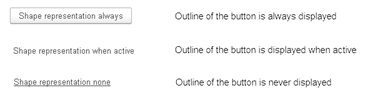
Fig. 315. Button shape display
You can specify several different ways to display the button shape:
-
Auto. In this case, for standard buttons, the display option specified for the command is used. In other cases, it is interpreted as Always.
-
Always. In this case, the button shape is always displayed (the first line in the example in fig. 315).
-
When active. In this case, in the normal state, the button is displayed without a background and a border (the second line in the example in fig. 315). If the mouse cursor points to a button, the input focus or the Mark property is set on it, a standard button with the specified border and background colors is displayed.
-
No. In this case, in the normal state, the button is displayed without a background and a border. When you hover the cursor over the text, an underline appears (the third line in the example in fig. 315) and the mouse cursor changes. The Mark property is not displayed whatsoever in this display option.
The property defines a display for buttons located on a form and in the command bars. The Shape visibility property does not affect commands located in a submenu.
Another way to control the appearance of a button is to set the View property. Depending on where the button is located, this property can take the following values:
-
Common button, Command bar button. In this case, the button is displayed as usual.
-
Hyperlink, Command bar hyperlink. In this case, the button is displayed as a hyperlink.
When you drag a button between a form and a command bar, the value of the View property is preserved, adapting to the command location.
7.7.8. Group
7.7.8.1. General information
When you develop a form, you can combine items in various ways. You can combine fields, form pages, commands, and columns.
A form can contain groups of controls. Users can group fields, pages, and commands. You can also create column groups for items of the Table type.
In the editor, you can create groups of the following types:
-
Regular group. Intended for combining form items. For more information about the ordinary group, see Regular group.
-
Command bar. A form item designed to accommodate buttons and groups. For more information about the ordinary group, see Command bar.
-
Pages. This group is intended for organizing a panel with tabs. Tabs can be located both vertically and horizontally. To add pages to such panel, add as many nested groups as the page should have on the panel. Inside the group of the Pages kind, there can be only groups of the Page kind, which are the groups of a special kind intended to form panel pages. This group may contain other nested items.
-
Column group. Allows you to combine columns in a table. With this kind of group, you can change the column grouping rule (vertical or horizontal grouping).
Groups can be nested. You can move form items between groups. This automatically determines the admissibility of such a transfer. If the transfer requires changing any item properties (for example, View), the change is performed automatically. This might also change or delete properties of subordinate items.
7.7.8.2. Regular group
A regular group can have different design options:
-
No. A group is not specifically marked up.
-
Slight highlight. The group title is displayed in large green font.
-
Standard highlight. The group title is displayed in large green font. Indents are formed around the group items (on each side).
-
Strong highlight. The group title is displayed in large green font. On the left side (for the entire height of a group) a green band is formed. An indent is formed from below.
If background color of a standard group differs from Auto, then the indentation appears on all sides of this group. The indent of a standard group is defined for each edge (left, right, up, down) but it does not apply if a group touches the edge of a form by its edge.
A standard group can be configured so that the user (in 1C:Enterprise mode) can collapse or expand the group. For example, there is a possibility to place information in a collapsible group that is not important when working with a form on a regular basis but may sometimes be required for viewing and analysis.
The behavior of the group is determined by the Behavior property:
-
Regular group. For such a group, the Behavior property is set to Regular. This group does not change its display in any way during user actions (except for programmatic modification of the composition and the external view of the group and its items).
-
Collapsible group. For such a group, the Behavior property is set to Collapsible. Such group can be collapsed or expanded by the user in 1C:Enterprise mode. The application developer cannot determine the current state of the group from 1C:Enterprise language. They also cannot forcibly collapse or expand a group. The initial state of a group is determined by the Collapsed checkbox. A group cannot be collapsed or expanded if it does not display a heading or it is not filled.
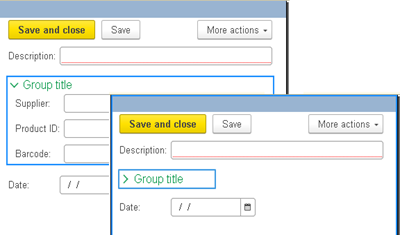
Fig. 316. Collapsed/expanded group
A user can manage the state of a group (collapsed or expanded) using a special image or hyperlink. To set the state control item, use the Display control property. You can also to set the group title (the Collapsed title property) that will be displayed if the group is in the collapsed state. If the Collapsed title property is not filled, then the normal group title will be displayed in the collapsed state.
- A pop-up group. For this group, the Behavior property is set to Pop-up. In the initial state, a pop-up group is displayed in the same way as a collapsed group.
When the heading of such a group is clicked, the group "pops up" over the parent form in a special window. At each time point on a form there can be only one pop-up group. This implies that pop-up groups cannot be nested. The nested popup group will appear as a collapsible group. Showing and hiding a pop-up group does not require a server call.
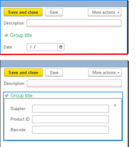
Fig. 317. Pop-up group.
A pop-up group must have a heading. Without a specified heading, a pop-up group behaves like a standard group. A heading acts as a text of the hyperlink clicking on which leads to displaying the window with the contents of a group.
When interactively navigating to an item (using the Tab button), which is located in a collapsible or pop-up group, the nested items of the group are automatically displayed in the required mode. When interactively exiting a collapsible or pop-up group (using the Tab button), a focus is transferred to the next form item (in the moving order). At the same time, the collapsed group remains expanded, and the pop-up group will be hidden.
An API is available from 1C:Enterprise language that allows you to:
-
Display a group. The Show() managed form group extension method is used. When this method is called:
-
A standard group does not respond in any way. An error is not generated.
-
A collapsed group gets expanded. The active form item remains unchanged.
-
A pop-up group is shown. The first item in the pop-up group becomes active.
-
-
Hide a group. The Hide() managed form group extension method is used. When this method is called:
-
A standard group does not respond in any way. An error is not generated.
-
A collapsing group gets collapsed. The active form item remains unchanged.
-
A pop-up group is hidden. An item becomes active in front of the pop-up group heading.
-
-
Get the group state. The Hidden() managed form group extension method is used. When this method is called:
-
For a standard group, False is always returned.
-
For a collapsible and pop-up group, True is returned if a group is collapsed or not shown (respectively). False is returned otherwise.
-
7.7.8.3. Command bar
The Command source command bar property defines a form item (Form as well as form items of the Table kind and fields of the Spreadsheet document field or Graphical schema field kind) that will provide "own" commands for display in the command bar. A composition of commands for display in a command bar is governed by the property Composition of the form item commands that is a source of commands.
When all buttons in the command bar have the OnlyInAllActions property set to False and not all buttons can be placed on the command bar (in width), the More button (with a submenu) is automatically formed in the command bar. This submenu contains all the command bar commands.
A group added to the command bar can be one of the following types:
-
Submenu. Allows you to create drop-down menus.
-
Button group. Allows you to create a group of buttons that will have the following properties:
-
A group of buttons is separated by separators on the left and right.
-
Each group of buttons can have its own source of commands.
-
You can set the density of buttons in a group: compact or standard (the Display property). The value of the Auto property is interpreted as Standard.
-
Fig. 318. Group button location
The Display property affects only those command bar buttons for which the Shape display property is interpreted as Always (see Buttons).
7.7.8.4. Using form groups
The View only group property affects all the items subordinate to a group.
The group property Allow change of composition controls an ability to change composition of a group in the process of setting up a form by a user. If the property is disabled, a user cannot change composition and the order of the items within a group. However, the property does not affect an ability of a user to change visibility of the group items.
If a group has the Heading data property, this data will be automatically displayed in the group heading. If the Heading property is set for a group, heading data is displayed in brackets after the heading: Heading (Heading data).
Any group of buttons (command bar, submenu, group of buttons, context menu) is populated according to the same rules. Buttons will be displayed in the following order:
-
The buttons provided by the command source this group is associated with.
-
The command interface buttons if the command source implies its inclusion.
-
The user commands added to this group.
-
More menu commands (All actions ) (only for a command bar).
-
The last one will be Reference (if it was provided by the command source).
If the above automatic order of disposition of buttons in a group is not satisfactory, then the following features can be used:
-
Clear the AutoFill checkbox for the form command bar, context menu or item command bar and add the necessary commands (in the desired order) manually.
-
Disable a command source of a command bar, then add the necessary commands (in the desired order) manually, then add a group of the Button group kind and set the command source for an added group.
-
There is a possibility to manually place the button associated with the standard command of a source command in the desired location on a command bar. In this case, the corresponding command will not be used when the source commands are automatically placed in the current command bar but will remain at the place where it was placed manually.
7.7.9. Supplementing a form item
7.7.9.1. General information
Addition of a form item is intended for displaying additional properties of the form item (addition of a form item) and managing these items. Form item additions are supported for the Table and PDF document field form items. The following add-ons are available:
| Add-on | Form item | Description |
|---|---|---|
| Search string | Table | Allows you to customize display of the search bar. |
| View state | Table | Allows you to customize display of a list of applied search queries. Cannot be located in a command bar. |
| PDF document field | Allows you to set up how to display additional properties of a PDF document displayed in a form. | |
| Search control | Table | Allows you to customize appearance of the search control button. |
To display form item additions in the item tree, expand the subordinate item tree for a form item that displays a table or a PDF document. Item add-ons are set up depending on the addition and the form item for which it is configured.
7.7.9.2. Add-ons for the Table item
The said add-ons are described in more detail below. A table available in the client application form enables you to perform interactive search in displayed data. Search can be carried out by using the following tools: search string, search dialog box, current value search, using search history and by setting the display period. The display period can be set only if the table displays a dynamic list that has a document or document journal table as the main list table.
As soon as search is completed, limited record set is displayed in the spreadsheet (from all those available to the current user) complying with search criteria. You can set up search parameters for all tables associated with the following form attributes: dynamic list (for details, see Dynamic list), value table, value tree, and table of any object.
To manage search capabilities, a form table supports the following Table form item properties:
- Search bar position. Defines the search bar position. Possible values: Auto, Command bar, None, Top, and Bottom.
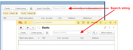
Fig. 319. Search bar in a table
If this property is set to Command bar, displayed parameters depend on the table data source:
-
Table will display dynamic list data. In this case, the search bar is displayed in the form command bar (if a dynamic list is a primary form attribute) or in a command bar associated with a dynamic list.
-
Otherwise, the search string is displayed in the command bar associated with the table being set up.
The search string contained by the command bar is always docked to the right edge of the command bar (along with the buttons located to the right of the search string).
If the property is set to None, the search string will be absent on the form, and a dialog box will open when the user starts typing in the search string.
If the property is set to Top, the search string is placed between the table command bar and the form table. If the property is set to Bottom, the search string is placed immediately below the table.
Auto is interpreted as No (if a table displays a value tree or list) or Command bar in any other case.
Calling the search string is performed as follows:
-
By pressing Ctrl + F
-
By mouse
-
When you start to type in a table (see Search in tables).
-
View status location. Describes where the view status is displayed: what fields were searched for and what values were searched for in each field. Possible values: Auto, None, Top, and Bottom.
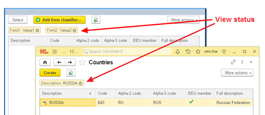
Fig. 320. Table search state
If the property is set to None, the view status will be absent on the form. Consequently, to determine whether a search has been completed or not will be possible will only be possible by the availability of the Cancel Search button.
If the property is set to Top, the view status will be placed between the command bar of the list and the table. If the property is set to Bottom, the view status will be placed immediately below the table.
Auto is interpreted as Top.
- Search control location. Determines where the search control button will be placed. The button opens a menu that contains search history (last 5 queries) and the following commands: Search by current value, Advanced search, Cancel search, and Set period. The Set period command is available only when a table displays a dynamic list that has a document or document journal table as its main table. Possible property values: Auto, None, and Command bar.
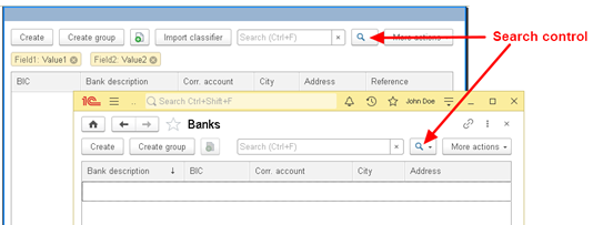
Fig. 321. Table search management
If the property is set to None, the search control button will be absent on the form (but the commands will be available through the More menu). The Command bar property value places a button on the command bar associated with the table. Moreover, the said button is placed to the right of the search line, if it is available in the command bar. If no search string is displayed in the command bar, search control button is available in the command bar in the ordinary way.
Auto is interpreted as Command bar (if a table displays a dynamic list) or None in any other case.
If there are several command bars on the form, with a single table of client application form being the source of their commands, the search string and the search control button will be placed in a single command bar only:
-
Either in the command bar of the table itself (if auto-complete is enabled for it)
-
Or in any of the rest command bars
For tables that display a dynamic list, there may be situations where using the search bar shows very poor performance. This can happen when a complex query is used to get dynamic list data, or full-text search is disabled, or it is impossible to effectively use full-text search to search in data. In such cases, as well as in other cases when the search bar must be available according to certain criteria, the 1C:Enterprise platform allows managing the search bar availability. For this, use the DynamicListViewSettings object and the same-named system storage setting. The setting can be either for a specific dynamic list or a default setting.
To use the setting, create the DynamicListViewSettings object, set the required value for the SearchStringViewMode property, and write the created object to the required settings (specific dynamic list settings or default settings). The search bar display is controlled by the value of the DynamicListSearchStringViewMode system enumeration.
For the search bar to be displayed only when full-text search is enabled, follow the example below or similar example:
SettingObject = New DynamicListViewSettings;
SettingObject.SearchStringViewMode = DynamicListSearchStringViewMode.ShowOnUsingFullTextSearch;
SystemSettingsStorage.SaveDefaultSetting("Common/DynamicListsViewSettings", SettingObject);In this example, the default setting is saved.
See also:
-
Default settings (see Default settings).
-
System storage of dynamic list settings (see Dynamic list settings).
7.7.9.3. Addition for the PDF document field item
A PDF document contains various additional information, which specifies the presence and state of signatures, indicates whether to store documents in archive formats (PDF/A), and so on. To display this additional information, use the special View state form item addition of the PDF document field form item field. To control the addition location, use the View state location form item property:
-
Top. The view state is located above the PDF document field.
-
Bottom. The view state is located below the PDF document field.
-
None. The view state is not displayed in the form.
-
Auto. It is interpreted as Top.
If a PDF document contains signatures, their state is displayed in the view state. If you click a hyperlink, which is a respective state item, you can check the signature state and get the check result.
7.7.10. Special command bars
In addition to creating customized command bars (the Group form item of the Command bar kind), the form editor provides an ability to work with the specialized command bars:
- Form command bar. The system provides a form command bar. Its visibility, position and content can be controlled. The visibility and position of a bar are controlled by the Alignment command bar property and the content is controlled by the AutoFill property. In addition to the standard commands that can be added to the command bar of a form, the commands from the section Form command panel of the global command interface are automatically added there.
If the main attribute of a form is a dynamic list and the AutoFill property is set on the command bar of a form, then the commands provided by this dynamic list will be automatically added to the form. If a form also contains a form item displaying a tree, then the form command bar will be supplemented with commands that are provided by the attribute associated with that item.
-
Table command bar. The command bar is automatically provided by the system for the form item of the Table kind. Its visibility, position and content can be controlled. The visibility and position of a bar are controlled by the Alignment command bar property and the content is controlled by the AutoFill property.
-
Item context menu. You can modify the standard context menu of the form item. To do this, display the context menu in the tree of form items using the context menu command Display context menu of the form item.
If a Group view item is added to the context menu of an item and specify another form item as the command source for this group, then the added group will be filled with commands (in the 1C:Enterprise mode) using the same rules as the context menu of an item selected as the source command.
When you use the context menu, keep in mind that if autofill is enabled for the context menu, then the context menu cannot be disabled from 1C:Enterprise language.
In all of the above command bars, one can add his own commands that are created using the command editor.
To place the commands located in the command bar of the form in any command bar:
-
Place the Group – Command bar item in the command bar.
-
Choose Global commands of the form command bar as a command source for this group.
If a command bar or a context menu that contains a group with the Global commands of the form command bar command source has a group that has the command source set to Form, then filling this group does not add commands related to the form command interface.
When you set (from 1C:Enterprise language) a command bar as the current item of a button, remember that the first command bar button will be activated, not the button used in the operation for setting the current item: ThisObject.CurrentItem = Items.CommandBarButton;. Also keep in mind that the DefaultItem property button is ignored when the button is placed in the command bar. If the user moves a button from the command bar to a form, then this property begins to be used.
Standard command bars and groups will be refilled if the following changes are made to a form while performing a context server call: data structure has been changed, form commands have been added or removed, form items have been added, removed or moved, table parameters of the managed form have been changed. In addition:
-
All user commands inserted into such bars and groups will be deleted.
-
Modified parameters of standard commands will be set to default values.
7.7.11. Conditional form appearance
In a form, you can set appearance of form items depending on the form attribute values. This feature is called Conditional appearance. Setting up the conditional appearance is similar to setting up the conditional appearance of the data composition system. Calling the conditional appearance settings is available from the properties panel of the root item of a form. It is not recommended that you use the conditional form appearance for designing dynamic lists if such appearance can be obtained by setting up the conditional appearance of the list itself. You can apply it to form items, form table fields, and input field items in multiple value edit mode. In this section, the last option is referred to as "multiple input field value". The subordinate MultipleValue element is available in the conditional appearance editor for fields that support this mode. In multiple value edit mode, conditional appearance of input fields is not supported for form tables and dynamic lists.
The following conditional appearance kinds are available:
-
Background color. Allows you to change the background color and used for:
-
Form items: input field, multiple input field value, text document field, table, and regular button.
-
Table fields: label field, input field, radio button field, and picture field.
-
-
Text color. Allows you to change the text color and used for:
-
Form items: label field, input field, multiple input field value, text document field, picture field, radio button field, table, regular button, hyperlink, text decoration, and picture decoration.
-
Table fields: label field, input field, and radio button field.
-
-
Font. Allows you to change the font and used for:
-
Form items: label field, input field, multiple input field value, text document field, picture field, radio button field, calendar field, table, regular button, hyperlink, text decoration, and picture decoration.
-
Table fields: label field and input field.
-
Note. Note. Changing the font of a form item using conditional appearance is not considered when determining the size of items.
-
Mark negatives. Allows you to set the highlighting of negative values. Applies to:
-
Form items: label field and input field.
-
Table fields: label field and input field.
-
-
Horizontal position. Specifies the horizontal position of the value and used for:
-
Form items: label field, input field, and text decoration.
-
Table fields: label field and input field.
-
-
Unfilled mark. Allows you to set the mark of an empty value and used for:
-
Form items: input field, table.
-
Table fields: input field.
-
Note. Tip. If you manage the Unfilled mark property using conditional appearance, then it is recommended that you set the Automark unfilled property to No for the field to be designed.
-
Text. Used to specify text and applies to:
- Table fields: label field, input field, and multiple input field value.
-
Format. Allows you to change the value output format and used for:
-
Form items: multiple input field value, group of the Page type, and group of the Regular group type.
-
Table fields: label field and input field.
-
-
Visibility. Hides the following table fields: label field, input field, radio button field, and picture field. Hidden cells are replaced with adjoining cells that become larger. An algorithm for stretching cells may vary in different client applications.
To manage the visibility of a column included in a group with the In cell column grouping, use the Show conditional appearance kind. You can find its description below.
It is not recommended that you use conditional appearance to hide entire rows in a table. Using conditional appearance to hide rows can have a negative impact on performance and result in incorrect display of the table contents.
When managing visibility on a mobile platform, keep in mind one feature. If table field visibility depends on data in the current row, then if there is no current row (see Table), the displayed column title may not match any visible row in the table. Headers will only match the current row only when the current row appears in the table for which conditional appearance is set. When using conditional appearance that depends on data of the current row, it is not recommended that you display the headers of such table on a mobile platform.
-
Availability. Used only to disable availability for:
-
Form items: multiple input field value.
-
Table fields: label field, input field, multiple input field value, radio button field, and picture field.
-
-
Read only. Used only to enable Read only mode for:
-
Form items: multiple input field value.
-
Table fields: label field, input field, radio button field, and picture field.
-
-
Show. Used only to hide the following values in a table column: label field, input field, radio button field, and picture field. This conditional appearance kind is recommended when you need to hide a table column that is located in a column group with the In cell grouping. If you need to hide columns that are not grouped with other columns or remain visible in separate table columns upon grouping, use the Visibility conditional appearance kind.
Note. For conditional appearance, the current computer date adjusted for the time zone of the 1C:Enterprise session is used.
If you use conditional appearance to design a form table column and the condition contains a field of the attribute displayed by the table to be designed, then the condition is calculated based on the current data of the table to which the column to be designed belongs. If a field to be designed is not related to a table, then the current data of the first form table (in the order of placement in the form editor) is used to calculate the condition.
With conditional appearance, you can set some types of appearance of the form items depending on the values of the form attributes, while the design of the form will be dynamic, that is, it will consider changes in the form data. No special action is required to change the form appearance. If dynamic list fields are used for conditional form appearance, set the Always use property for these fields.
Let's look at an example of a conditional appearance.
Suppose, in the Goods consumption document we need to select those table rows in which the number of items is less than 10 pieces.
To do this, specify the following conditions in conditional form appearance:
-
Conditional appearance type: text color. As the color value, select Highlighted text from the style.
-
As the condition, select the following expression: Object.Goods.Count Less "10". In this expression, the Object is the main form attribute, Goods are the table, and Count is the table attribute.
-
As the fields to be designed, select the entire Goods table.
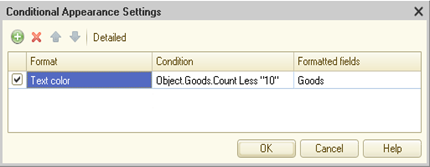
Fig. 322. Setting up conditional appearance
You can see the result of the conditional appearance in fig. 323.
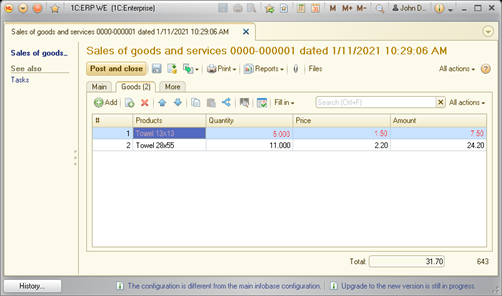
Fig. 323. Conditional appearance result
Thus, the font color of the first row of the table became red since the number of goods in this row is less than 10.
However, it is not always necessary to highlight the entire row with a special color, but you need to highlight a cell of the table bearing the quantity.
To do this, the specified conditional appearance must be changed. Instead of the entire Goods table, we need to set a specific field: Count.
In this case, only single field will be highlighted:
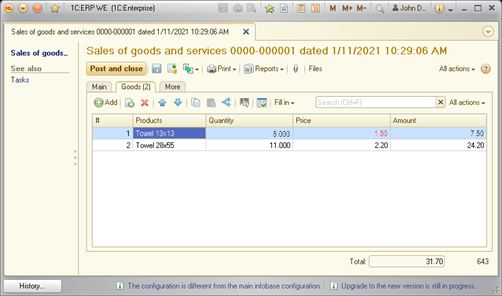
Fig. 324. Designing a single table field
Also note that you can use the values of columns that are not related to infobase data in the condition expressions.
7.7.12. Form item behavior
If field headers or decorations of the Label kind use alphabetic characters not supported by the font set for these form items, then the length of the rows to be displayed may be calculated incorrectly. As a result, the rows in these form items may not be displayed completely.
The managed form items associated with the standard Reference and Posted attributes cannot be edited.
If you need to use fonts in your solutions that are different from the one defined by the Auto value of the corresponding property, it is recommended that you limit yourself to the following fonts:
-
Style fonts of 1C:Enterprise:
-
Small text font
-
Standard text font
-
Large text font
-
Very large text font
-
-
Vector fonts out of the "MS Core Fonts" package:
-
Andale Mono
-
Arial
-
Arial Black
-
Comic Sans MS
-
Courier New
-
Georgia
-
Impact
-
Times New Roman
-
Trebuchet MS
-
Verdana
-
Webdings
-
Using other fonts does not guarantee correct display of form items in various client applications or operating systems.
The behavior of the form fields of the label, image, label decoration, and image decoration kinds does not depend on the setting of the ReadOnly mode (both for specific form items and for the form as a whole).
If theLength and Accuracy properties for the form attribute of the Number type are set to the same values, the input field allows you to enter any number. However, when you try to leave the input field, you will see a message about incorrect input if the entered value is not in the range from 1 to 1 (excluding 1 and 1).
If the actions that call the server and rebuild the form are performed in the OnChange handler of a field located in a form table, the OnEditEnd and BeforeEditEnd event handlers of this table will not be called.
A spreadsheet document located on a form is scrolled vertically line by line.
If the input field or the label field has theHeight property set to a value greater than 1 and the Stretch vertically property is set to Auto, then this value will be interpreted as True. That is, the specified form items will be stretched vertically.
A drop-down list of the input field adjusts its width to the width of the items displayed in it. The minimum width of a drop-down list is defined as the maximum value of the following values:
-
Fixed value specified in the platform
-
Value of the DropListWidth property of the managed form field extension for the input field
If one of the items displayed in a drop-down list is wider than the calculated minimum width of the list, then the width of a drop-down list is equal to the width of the widest displayed item, but not greater than:
-
Thin client screen size
-
Web client form size
In the event that when opening the form, the visibility of the form item is dynamically changed, then in the opened form, the input focus will receive an item following the item for which the visibility was changed. You can set the input focus to another item manually.
7.7.13. Rules for placing form items
7.7.13.1. General information
Form items are placed in a rectangular logical grid. This grid is hierarchical, with the uppermost level of a logical grid being the grid specified for a form, and in the logical grid cell its logical grid can form if the form item that is in this cell is a group of the Normal group kind or a group of the Page kind. The actual form, a group of the Normal group kind and a group of the Page kind will be called the form grouping item. The width of a logical grid cell is determined by the width of the form item located in this cell, and its height is determined by a logical string. The concept of "logical string" is not described by certain numeric parameters. The easiest way to show this concept is with an example. To do this, create a form with the following structure:
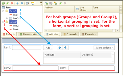
Fig. 325. Form structure
The following items are visible in the editor:
-
The form itself with vertical grouping set and the form command bar disabled.
-
The Group1 group without display with horizontal grouping. The Item1 and Item3 items are placed in this group.
-
The Group2 group without display with horizontal grouping. The Item2 and Item4 items are placed in this group.
For some reduction in the size of the image, for the Item3 table, the height of the table is reduced. This change does not affect the operation of the item placement algorithm (in this example).
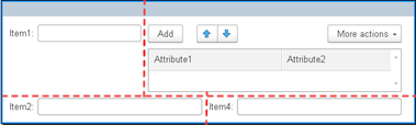
Fig. 326. Logical grid concept
In fig. 326, two rows of the logical grid are displayed. The first row contains the Item 1 and Item 3 items, and the second line contains Item 2 and Item 4. It is easy to see that each of the described rows will have a different height. But, nevertheless, exactly two rows will be used in the form logical grid. Thus, the height of the logical grid row is calculated based on the height of the tallest item of all items that are located in the same horizontal row. For the first row, the height will be determined by the height of the Item 1 and Item 3 items. For the second row, it will be determined by the height of the Item 2 and Item 4 items.
Also note that each form row has its own cell width. This is because Item 1 and Item 3 are in the same grouping item, and Item 2 and Item 4 are in another grouping item. Within each grouping item, the items are placed separately.
Thus, it is clear that in this example there are three logical grids:
-
A logical form grid. For this example, a 2 x 1 grid is set: two items (groups) with vertical grouping specified for a form.
-
A logical group grid with the Item 1 and Item 3 items. This group defines a 1 x 2 grid: two items (Item 1 and Item 3) in a group with horizontal grouping for the group. This grid is nested in a logical form-level grid.
-
A logical group grid with the Item 2 and Item 4 items. This group defines a 1 x 2 grid: two items (Item 2 and Item 4) in a group with horizontal grouping for the group. This grid is also nested in a logical form-level grid.
In future, when mentioning the placement of items, a logical grid described above will be assumed. When you develop a form, follow these simple recommendations to ensure that your form works on all supported screens and resolutions:
-
If possible, use default values for the item properties.
-
Minimize the explicit indication of the size of form items.
In general, the rules for placing form items as follows:
-
Form items are placed in two directions:
-
Horizontal direction. Each new form item is located to the right of the previous one. Such a group can be represented as a 1 x N matrix, where N is the number of items in the group.
-
Vertical direction. Each new form item is located below the previous one. Such a group can be represented as an N x 1 matrix, where N is the number of items in the group.
-
The placement direction depends on the Grouping property of the form grouping item: form or group. When placing, there are no restrictions on the number of the displayed items.
Thus, by combining groups with different grouping settings and nesting groups one into another, you can create quite complex (in structure) forms. Within the system, you can control the alignment of items, both within one grouping item and between them (for more information, see Aligning form items).
-
The order in which items are displayed is determined by the order in which they appear on the Items tab of the form editor.
-
You can manage the placement of items using the following parameters:
-
Horizontal and vertical item spacing
-
Item size
-
Item alignment
-
Ability to stretch items horizontally and vertically
-
Other parameters
-
-
The item placement area is limited by the size of the window in which the form is generated. The window size is limited by the size of the working area of the main window or screen settings. If, as a result of placement, the total size of items exceeds the size of the window allocated to the form at the corresponding (vertical or horizontal) coordinate, then scroll bars will appear in the form.
-
The rules for placing items within a group are equivalent to the rules for placing items inside a form.
The placement of items is simultaneously influenced by both the general placement rules (described above) and the processing of various parameters that affect the placement. The total number of combinations of all influencing parameters is extremely large, so the operation of sets of similar properties will be discussed further. We will not look into combinations of all influencing properties. A description of the properties that affect a location of items as well as placement algorithms will be given later in this section.
A formation of the form, as it is displayed to a user, consists of two stages:
- On the server:
-
The system retrieves a tree of form items.
-
Items that are disabled by functional options (see Functional options and functional option parameters), access rights (see Roles and access rights), and the user (using the form settings dialog box) are excluded from the item tree.
-
The resulting item tree is used to generate a form description. It is an internal form presentation, which is not yet suitable for direct display. This description defines actual values for properties set to Auto. No other calculations are currently in progress (form element sizes, item visibility, and so on).
-
The resulting form description is passed to client.
- On the client:
-
The client application determines characteristics of the screen where a form will be displayed: orientation, sizes, used fonts, and so on.
-
Based on the information received, the sizes of the form items are determined, the visibility of the items is processed, and so on. Groups and tables or which there are no visible subordinate items are also excluded from the form description. The result is a form description that almost completely corresponds to how the user will see the form: the items are placed in the cells of the applied grid, and the sizes of the items are calculated. In this case it should be understood that a size of items depends on the current font, features of an item itself and the client application used.
-
The resulting "almost form" is converted into a real set of controls of the target platform (thin client, thick client, web client, mobile device) and displayed to the user.
7.7.13.2. Grouping and merging form items
Form items can be grouped using the special form item: Group. Grouping allows you to simplify the management of items, visually select items on a form, and control the grouping of items (using the Grouping property). Several types of the Group form item are available, each of which has its own grouping control particularities:
-
Command bar. Grouping control is not available.
-
Page. Allows you to control a grouping of items.
-
Standard group. Allows you to control a grouping of items.
-
Column group. Allows you to control a grouping of items (form table columns).
For a group of the Standard group or Page kind, a grouping (the Grouping property) of items can be set. Let's take a look at an example of using such a grouping.
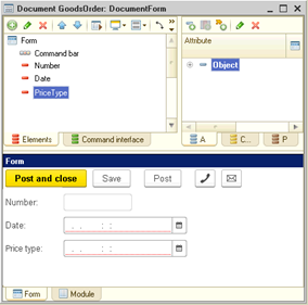
Fig. 327. Vertical grouping
Let's consider creating a document form. In this case, a grouping of form items is selected as Vertical but we want such document attributes as Date and Number to be located not in two rows but in one.
To do this, we will create a group named DateAndNumber, set the Grouping property to the Horizontal value and place the form items Number and Date there.

Fig. 328. Horizontal grouping
A combination of the above methods is the Horizontal if possible method. In this case, the items will be arranged horizontally if the dimensions of the parent grouping item allow for placing all the subordinate items horizontally. Otherwise, items will be placed vertically. This placement is performed by the system automatically.
It is possible to change the arrangement of columns in the form table in a similar way. As an example, consider a list form that has the Code and SKU columns.
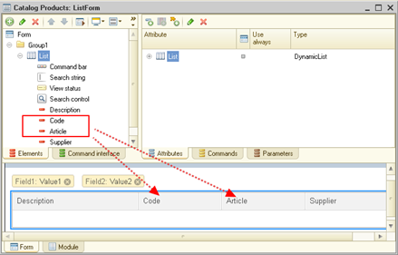
Fig. 329. Original column arrangement
However, in our list it is necessary to make so that the code and the SKU are located in two rows, one under the other. To do this, create a group of columns subordinate to the List item and name it CodeAndSKU (for example). Then set a vertical grouping for the group of columns.
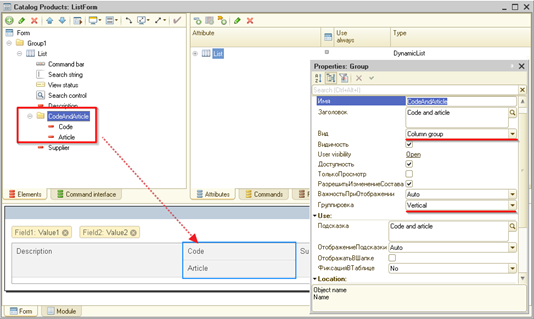
Fig. 330. Vertical column group
But there is a need for the code and the SKU to have a common title (for example, Codes). To do this, follow these steps:
-
For CodeAndSKU column group, set the Title property.
-
Then for the same group, set the Show in header property.
-
Set the Show title property.
As a result, the following form will be created:
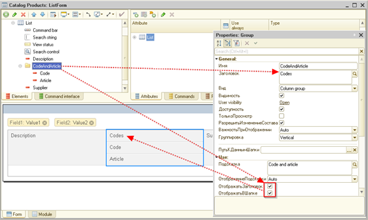
Fig. 331. Group title
Now make sure that the titles of the Code and SKU columns are not displayed on the form (so that the height of the table header does not increase). To do this, follow these steps:
-
Select the Code and SKU items.
-
Clear the Show in header checkbox. This operation can be done for each item separately (without selecting two items at once).
As a result, the following form will be created:
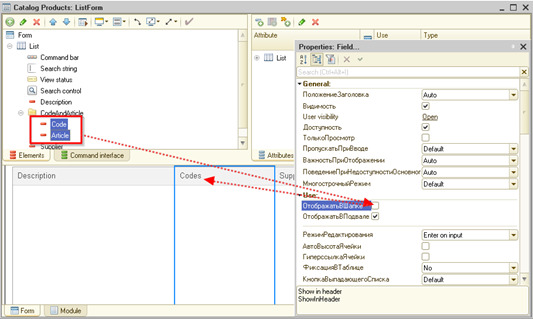
Fig. 332. Displaying the group title only
Thus, within the table, you can flexibly change the arrangement of columns and their design in order to obtain the desired look of the table.
Note. Note. Groups can have unlimited nesting. In this case, the Grouping property can be different for each nested group.
7.7.13.3. Form item sizes
When determining the actual size of each form item the system is guided by the limitations that the application developer has established during form development. You can control the following item properties:
-
To control the width of an item:
-
Width. The item width.
-
AutoMaxWidth. Indicates that the system automatically calculates the maximum width of this item. Available for some items.
-
MaxWidth. The maximum item width specified by the application developer. Available for some items.
-
-
To control the height of an item:
-
Height. An item height.
-
AutoMaxHeight. Indicates that the system automatically calculates the maximum height of this item. Available for some items.
-
MaxHeight. The maximum item height specified by the application developer. Available for some items.
-
-
It should also be mentioned that the linear dimensions of an item are influenced by values of the HorizontalStretch and VerticalStretch properties.
The width and height of a form item is specified in abstract values depending on the font set for this element, taking into account the particularities of a display of this item and a client application. It should also be remembered that when explicitly specifying a width (or height) of an item, the actual dimensions will depend on the operating system used, its settings, and a client application. Besides the fact that actual dimensions of items depend on the kind of client application (thin client, thick client or web client), these dimensions also depend on a web browser used and its version. Note that the width and height of a form item do not describe the size of the item data area (see General information). These parameters describe the overall dimensions of an item, excluding the tile, command bars, and so on.
The actual size of a form item in 1C:Enterprise mode may not match the specified size. When determining dimensions of items, the system considers font (and its sizes) specified in the properties of form items.
Note. Note. Changing the font of a form item using conditional appearance is not considered when determining the size of items.
Calculation of the dimensions of an item along any axis depends on the state of stretching along this axis:
-
Stretching is disabled:
-
The explicitly specified Width (Height) property determines the size of the item. In this case, the properties that determine the maximum size of the item are ignored.
-
The Width (Height) property is set to 0. This means automatic sizing of the item. In this case, the size of the item along the corresponding dimension is determined by the content of the item. The size of the item cannot exceed the maximum size. The maximum size of the item along the corresponding axis can be specified either automatically calculated (the AutoMax... properties) or explicitly set manually (the Max... properties).
-
-
Stretching is enabled:
-
The explicitly Width (Height) specified property determines the "weight" stretching/shrinking ratio.
-
The Width (Height) property is set to 0. This means automatic sizing of the item. The system will select the appropriate size based on the data type, content, and other parameters. The size of the item cannot exceed the maximum size. The maximum size of the item along the corresponding axis can be specified either automatically calculated (the AutoMax... properties) or explicitly set manually (the Max... properties).
-
If the maximum width or height of an item is set to 0, then the item can be resized unlimitedly along the corresponding dimension.
-
When determining the width of the input field, the following features apply:
-
If the MaxWidth property is set explicitly (the AutoMaxWidth property is disabled), then it defines the maximum width in characters. In this case, for example, the input field buttons fit this width.
-
If the AutoMaxWidth property is enabled, then the maximum width is determined depending on the type of input field, and the buttons are also arranged there for better alignment with the right border. The Width property in this case works differently. If it is equal to 0, the width is determined depending on the input field type and the number of enabled buttons is added to it.
-
-
When determining sizes of items, the limiting factor "from above" is sizes of parent grouping items: forms, groups, and pages. The dimension of a grouping item limits the resizing of nested items. In other words, if a group has a given width and stretching is forbidden, then for all the subordinate items the specified group width will be a constraint when calculating a width of these items.
7.7.13.4. Stretching groups
Resizing a regular group (stretching) depends on the items in a group and on the values of the Stretch vertically and Stretch horizontally properties:
-
Auto. Does not affect the stretchability of child items. If a group itself has displayed appearance items, for example, a vertical or horizontal line, or a background color is set for it, then the corresponding items will have dimensions corresponding to the largest child and stretch within the same limits.
-
Yes. Does not affect the stretchability of child items. The items that correspond to the group itself (appearance items, an area with a background color) or empty space in the absence of such items will stretch without restrictions. If a group has the Item and title alignment property set to Items right,..., then such items will move along with the right border of the group if the items themselves cannot stretch.
-
No. The group dimensions are determined by the standard dimensions of the child items. Within these dimensions, the child items can stretch. Further stretching/shrinking of the child items is not possible. The same dimensions will be used for the appearance items of the form itself and its background color. If a group has a width (height) specified, then its dimensions along the corresponding axis are defined as the maximum between the standard dimension of the child items and the specified value.
7.7.13.5. Width and height of groups
If a group has an explicit width or height, then when calculating the dimensions of the child items, an attempt is made to fit them into a given constraint unless the superior group or the dimensions of the target device have imposed a more restrictive constraint.
If, as a result of the calculation, the width of the child items is less than the specified width of the group, then the group expands to the specified value.
If as a result of the calculation the width of the child items is greater than the specified width of the group, then the width of the group is ignored. If the calculation is performed in Designer and the Show layout generation issues mode is enabled, then the corresponding error is displayed in the message window.
If a group has a displayable title, then it is calculated according to the same rules as these for the child items. If a group has a width specified, then an attempt is made to fit the title into it by line wrapping. If the width of the title is still larger than the width of the group, then the width of the group will not be less than the width of the title (larger if the width of the child items was greater).
7.7.13.6. Controlling the spacing between items
For some specific forms, it may be necessary to place items more densely or, conversely, more sparsely. Such a requirement may arise for the entire form as well as for some of its fragments. Moreover, it may be necessary to change the distance between items both vertically and horizontally.
To solve this problem, the grouping items have the Horizontal spacing and Vertical spacing properties. By changing these properties, you can achieve the required density of the form items.
The Auto value set for any of these properties means that the spacing will be determined by the parent grouping item. For a form, the Auto spacing value is determined by the platform.
The figure below shows an example of two extreme options for setting the vertical spacing between items.
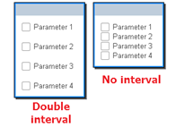
Fig. 333. Various vertical spacing
7.7.13.7. Aligning form items
7.7.13.7.1. General information
A form item consists of a data area, which is a form item area that displays data, and a title area (title), which is a form item area that displays a title (see fig. 334). Standard data area width determines the width of the data area and has the following properties:
-
Determined by the data type of the attribute associated with the form item or the Width property of the form item.
-
Does not depend on the Stretch horizontally form item property.

Fig. 334. Form item structure
When performing alignment, the orientation of titles and data areas is formed relative to an imaginary line that runs along the border between the titles and data of all items located in the grouping item. The size of the title area is calculated by the maximum width of the title of all items.
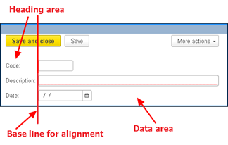
Fig. 335. Baseline for alignment
7.7.13.7.2. Alignment in group borders
Within a grouping item, the alignment of borders of form item components is determined by the Item and title alignment property. This property allows you to set the following alignment options:
- No. In this case, the data area is located immediately after the end of title. No alignment is performed.
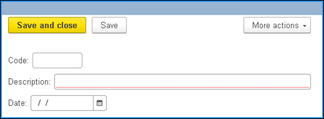
Fig. 336. Alignment: none
- Items left, titles left. This is the alignment mode used in 1C:Enterprise version 8.3.6 and earlier. In this case, the field titles are aligned to the left border of the grouping item. The data areas are also aligned to the left border.
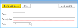
Fig. 337. Alignment: left-left
- Items right, titles left. In this case, the field titles are aligned to their left border, and the data is aligned to the right border.
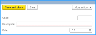
Fig. 338. Alignment: right-left
- Items left, titles right. In this case, the titles are aligned to the right border, and the data is aligned to the left.
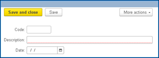
Fig. 339. Alignment: left-right
- Items right, titles right. In this case, all parts of the form item are aligned to the right border of "their" area.
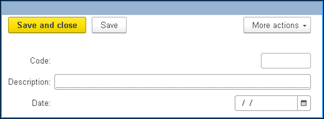
Fig. 340. Alignment: right-right
As mentioned above, the alignment of borders is carried out within the current grouping item. In this regard, the resulting alignment of items may not be quite satisfactory.
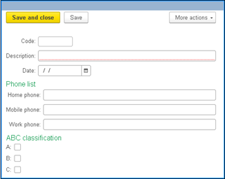
Fig. 341. Through alignment by default
However, in a particular case, it may be necessary to align the checkboxes in the ABC classification group with respect to the same imaginary line as the first three items (Code, Name, and Data). To control this behavior, use the Through alignment property (available for a managed form group). If the ABC classification group has this property set to Use, then the alignment will somewhat change:
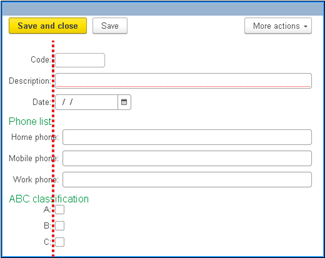
Fig. 342. Through alignment. "Use" from below
You can see that the ABC classification group began to use the same line for alignment as the first three items. This behavior applies only to the first left items which are located in a group. The actual alignment is implemented by setting the same width for the item titles that are located on the left. If this property is set to Auto, then the through alignment is determined by the platform itself. Explicitly specifying the Do not use value for this property will result in such a grouping item not being aligned taking into account the items that are not included in the group.
The through alignment is not used for groups whose Behavior property is set to a value other than Standard.
7.7.13.7.3. Alignment between groups
When developing complex forms, there may be problems related to the mutual alignment of form items if these items are located in different groups.
Suppose you need to create a form that contains checkboxes for selecting actions and notes for these actions. The checkboxes are implemented as checkboxes themselves (form items), and the notes are implemented as decorations of text kind. The checkboxes are located in one group, and the notes are located in another. To simplify the example, the groups have disabled the display of titles and the selection of the groups themselves.
As a result, the following form appears:
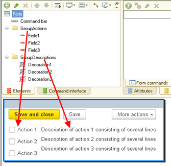
Fig. 343. Alignment between groups
There is an obvious problem in the example: vertical alignment of the items in the groups does not match the desired one, since the checkboxes have a greater height than the decorations.
To solve this problem, use the Consolidated group form group property. Let's see how this property works.
When a group has this property set, then in this case the whole group is considered to be a single item (this is how the mechanism of placing form items is configured). This property is set to this namely value when creating a new group.
If a group has this property disabled, then the item placement mechanism will analyze all items of this group as separate items. So, if you disable this property for the ActionsGroup group (in fig. 344), then the form will look as follows:
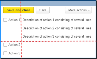
Fig. 344. Alignment between groups
Let's take a closer look at what is shown in fig. 345. The main question is this: why is the first row of the GroupAction item as tall as the entire DetailsGroup item?
As mentioned at the very beginning (see General information), the horizontal unit of measure for placing form items is a row. The row height is defined as the maximum height of one of the form items that are located along the same horizontal line and have the same top borders (assuming that the Vertical alignment within group property of all items is set to the same value). As long as both groups had the Consolidated group checkboxes selected, each group was treated by the item placement system as a single item. Therefore, the groups were located on the form at the same level, and within each group, the alignment worked in its own way.
After the GroupAction item had the Consolidated group checkbox cleared, the group was no longer treated by the placement mechanism as a single item. Each item of the group is counted separately. But for the GroupDetails item, the Consolidated group checkbox is still selected. This means that the placement mechanism assumes that the Action1 item and the GroupDetails item are located on the same row and the height of this row matches the height of the GroupDetails item.
If you now clear the Consolidated group checkbox for the GroupDetails item, the form will look as follows:
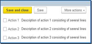
Fig. 345. Alignment between groups
The result is the desired behavior: the size of the decorations no longer affects the overall alignment of the items.
Thus, using the Consolidated group property, you can create groups consisting of several columns and rows at the same time, with support for alignment of items in all columns and rows:
-
The property is set. A group is considered a single item.
-
The property is reset. Every item that is part of a group with the reset property is considered a separate item.
In addition, a group that has the Consolidated group property reset (the group becomes "separated") has the following features:
-
Only the following group properties are used to define group title parameters: Grouping, Background color, Show title, and Display. The Grouping property is used to determine the order in which the items of the current group are placed in the parent grouping item.
-
If the Show title property is set to True, then the group title is placed in the top-level group as the first item while grouping is observed, that is, for horizontal grouping, the title will be placed to the left of the other items. For vertical grouping, it will be placed above other items.
-
Separators are not generated (see Item separators).
7.7.13.7.4. Controlling the relative position of items
When developing various forms, it becomes necessary to control the relative position of form items. For example, you want one or more buttons to be centered in a group or form.
To organize this location, there are several properties:
-
Horizontal alignment of subordinate items. Available for grouping items (form, regular group, and page type group). Defines what the horizontal relative position of the subordinate items within the grouping item will be.
-
Vertical alignment of subordinate items. Available for grouping items (form, regular group, and page type group). Defines what the vertical relative position of the subordinate items within the grouping item will be.
Below is an example where for a group with horizontal arrangement of items, the buttons are located in the center of the group, and for a group with vertical arrangement of items, the buttons are located at the bottom of the group.
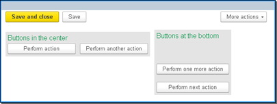
Fig. 346. Controlling the relative position
In the event that any of the described properties is set to Auto, this means that the actual value of the property is determined through the properties of all parents of the same name, and for a form the value of a property is automatically selected by a platform. The bypassing of the parental items will end when the desired property is set to a value other than Auto.
Keep in mind that if the value of the Horizontal position property is different from Left for the grouping item, then the alignment of titles stops working for subordinate items.
7.7.13.8. Item separators
In some cases, the platform can form separators on a form. These are special form items that can be used to resize adjacent form items.
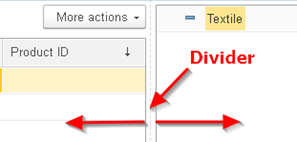
Fig. 347. Separator
The separator is automatically generated when placing form items if all of the following conditions are met:
-
Both separable items are stretched in the appropriate direction.
-
There are no other items between the items to be separated (they are located side by side).
-
The height of each of their separable items is at least two rows.
-
The value of the Width (or Height, depending on the separator orientation) property of each of the separable form items is greater than the minimum width (height) and less than the maximum width (height) of the form item. The maximum dimensions are set using the Max... or AutoMax... properties. The minimum width and height are automatically determined by the platform.
-
None of the items to be separated are auto-wrapped labels.
-
The size of the appropriate spacing between the items of the parent group (or form) is sufficient to accommodate the separator.
-
A parent group (or form) has no child items of the Group kind of the Standard group type with the United property enabled.
7.7.13.9. Adapting forms to the mobile client
The mobile client interface is similar to the mobile platform application interface. This means that one form is displayed on the screen at a time, the screen has a relatively small width. As a rule, horizontal scrolling of a form is not applied on mobile devices. However, vertical scrolling of forms is acceptable.
Based on these prerequisites, the mobile client attempts to automatically rebuild the form so that it fits the screen of a mobile device. In the adaptation process, the width of form items is reduced for those items whose width in the configuration is set so that it exceeds the actual screen width on a mobile device. The width of such items is changed so that they fit (in terms of width) the screen in the current orientation of the mobile device without horizontal scrolling. In addition to changing the width, the system might attempt to reduce the number of displayed form items to improve the visual appearance of the form. To control the need for such restructuring, use the Method of collapsing items by importance form property (CollapseItemsByImportance). The Auto value is interpreted as Use.
To make it easier for the mobile client to adapt a form, form items (and columns of tables) have the Display importance property (DisplayImportance). By changing the value of this property, developers can achieve the desired form presentation on the device screen. This property value is processed by the mobile client as follows:
-
More important items are given more space on a form.
-
If a more important item is located below less important ones, and these less important items occupy more than three rows of a form, the less important items are combined and placed in a collapsible group. Keep in mind that the height is more important than the number of items in any case. In other words, three form rows can fit three items if each of them occupies only one row or one item that occupies three rows.
-
If the first or last of the collapsible items is the command bar, it is not collapsed as it can refer to an important item.
-
If a more important item is located within a hierarchy of groups or pages, and less important items are located above it in different hierarchy points occupying more than three rows, a collapsible group is generated at each hierarchy level.
-
If there are several items of higher importance, less important items between them are placed in a collapsible group if they occupy more than three rows.
-
Less important items that are below the last more important item are not collapsed.
-
If items of different importance are also located inside a collapsible group, the algorithm is applied recursively to this group.
-
The collapsible group title is generated as follows:
-
If an already existing group becomes collapsible, the group title is preserved.
-
If a single item with a specified title is added to a collapsible group, this item's title is used for the group.
-
Otherwise, the group title is a combination of comma-separated titles of the items included in the collapsible group.
-
If the DisplayImportance property is set to Auto for a form item, the actual property value is determined by the following rules:
-
VeryHigh for the form item that displays data from the main form attribute (and subordinate attributes).
-
High if the item is stretched vertically and is one of the following items:
-
Form table displaying a dynamic list
-
Spreadsheet document field
-
Chart field of any kind/type
-
Formatted document field
-
HTML document field
-
-
If an item is a command bar, then:
-
High if the source of commands for the command bar is the controlled form.
-
The importance value of an item that is the source of commands for the command bar.
-
The importance value of the most important item in the same group as the command bar provided that no command source is set for the command bar.
-
-
The Standard value for all other items.
7.8. Form command interface
The form command interface consists of:
-
Form navigation panel
-
Form command bar
You can edit the form command interface: add new commands, use existing commands, and so on.
Note that the form command interface is edited on a separate tab in the form editor and describes the composition of the navigation panel of the auxiliary window in which the form is displayed, and partly the composition of the form command bar. Basically, this mechanism is needed to configure the global interface commands that need to be displayed on the form in these two panels. A composition of the form command bar is defined both directly in the structure of items and in the editor of the command interface.
The command automatically enters the command interface of the form in case the parameter kind of the parameterized command matches the kind of the main attribute of the form.
In addition, there is a possibility to forcefully add a command to the desired command interface bar. To do this, simply drag it into the desired group of the desired command bar.
The selected Autoposition checkbox indicates that the command sequence generated by the system by default will be used. If it is cleared, the order of commands can be edited.
To configure the visibility of the commands that are located in the command interface bars, you can clear the checkbox in the Autovisibility column and change the value in the Visibility column.
7.9. Working with a form from the 1C:Enterprise language
7.9.1. Opening a form
There are two ways to open a form:
-
Use the OpenForm() method.
-
Use a combination of the GetForm() method and the Open() method of the ClientApplicationForm object.
In any of these cases, there is a possibility to pass the form parameters to the form to be opened.
It is recommended to use the OpenForm () method in all cases, except for a need to open a form in a modal mode and then get the result of the functioning form working through the attributes of the form being opened.
This feature is due to the fact that the return value of the modal form will be the data that the form itself returns and a developer will not have an access to the ClientApplicationForm object to get the form attributes. If you first get the form using the GetForm() method, you can access the attributes after the Open () method completes. If you need to open the form in blocking mode, use special approaches. For a detailed description of them, see Different approaches to modality.
Example 1:
// Open a list form of
the goods catalog
// in the "View
only" mode
Parameters = New Structure("ReadOnly", True);
OpenForm("Catalog.Goods.ListForm", Parameters);Example 2:
// Open a modal form
and get access
// to form attributes
after closing it
Form = GetForm("CommonForm.SelectionPeriod");
Result = Form.Open();Note. Note. It is not recommended that you perform software opening and closing of the same form in one call to 1C:Enterprise language.
It is not recommended to place in the event handler of the OnOpen form the program code for opening any other form as this may lead to a violation of the window display order. In this case, it is recommended to use a wait handler for a short time interval or open other forms interactively, for example, by pressing a button. It should also be remembered that the exceptions that occur during opening of a form are not intercepted in the 1C:Enterprise language and are displayed to a user "as is".
7.9.2. Redefining the form being opened
In application systems, the problem of opening various forms with different parameters of an object (or current environment) may arise. For example, for an item of the Products catalog, you need to open different forms for the actual product and the service. Or for some automated workplace, there is a need to open different forms depending on current settings of a user.
To perform this task, in the object manager module, create the FormGetProcessing event handler. In this handler, perform all the necessary checks and decide which form to open. This handler is called only if an attempt is made to open a standard form of an object using the default form names.
So, when opening a form of the Products catalog item in the following case, the handler will be called.
OpenForm("Catalog.Products.ObjectForm");However, the handler will not be called if you try to open the form as follows.
OpenForm("Catalog.Goods.Form.ItemForm");Let's take a closer look at an example with different forms of the catalog item form.
When the form is opened, the Type attribute of the Products catalog will be analyzed, and if this property is set to Enumerations.ProductTypes.Services, open the FormServices form of the Products catalog.
Procedure FormGetProcessing(FormType, Parameters, SelectedForm, AdditionalInformation, StandardProcessing)
If FormType = "ObjectForm" AND Parameters.Key.Type = Enumerations.ProductTypes.Service Then
SelectedForm
= Metadata.Catalogs.Goods.Forms.FormService;
StandardProcessing
= False;
EndIf;
EndProcedurePlace this handler in the Products catalog manager module.
Note. Note. The FormGetProcessing handler is not called when you try to open common forms, constant forms, settings storage forms, external reports, and external settings storage processors.
7.9.3. Modifying form item properties
In the process of working with a form, situations arise when it is necessary to change any property of form items, for example, the availability of items.
To perform these actions, use the Items collection. This collection provides access to a list of all form items (without regard to hierarchy).
To access the hierarchy of items, use the Parent and ChildItems properties (for the group items, table, and a form itself).
So, disabling the availability of the PriceType form item is as follows:
Items.PriceType.Availability = False;Attention should be paid to a feature of setting the properties ReadOnly, Accessibility and Visibility for the items containing subordinate items. Setting a property for the parent item also affects all subordinate form items. In this case, a value of the variable property of an item itself does not change. In other words, the actual value of the properties ReadOnly, Accessibility and Visibility of a specific item of a form is defined as the addition "by AND" of the values of these properties of all the parents of the item.
For example, we have a CurrencyDocument group, which consists of the Currency and CurrencyExchange input fields. If it is necessary to make the entire group inaccessible, it suffices to do the following:
Items.DocumentCurrency.Availability
= False;Note. Tip. When programmatically modifying the properties of form items, avoid the unnecessary modification of properties for which the Change property on client requires accessing server in Syntax Assistant. This slows down the work of a form and requires unnecessary calls to server.
Note. Note. If the modification of the form items leads to a change in the arrangement of the items on the form (for example, when the visibility of the form items changes), then various event handlers associated with the activation of items may be called (for example, a table will activate theOnActivateRow event).
Programmatically changing the View property of a form item that has an extension (field, table, group, decoration) leads to a creation of the new extension of the form item. The properties of the form item related to extension are set to default values and are not transferred from the item extension that was taking place before change to the View property.
Note. Note. Keep in mind that form item properties related to the displayed data (for example, DataPath, TitleDataPath, and so on) can be changed only for new form items or after changing the form item appearance.
7.9.4. Form modification
You can programmatically modify a form. You can modify (create, modify, and delete):
-
Form attributes
-
Local form commands
-
Form items
Note. Note. Only those objects that are created from 1C:Enterprise language can be deleted.
A general scheme of the programming work with a form can be represented, as follows:
-
Changing the form attribute set
-
Changing the form command set
-
Changing the form item set
In particular, it should be noted that a work on adding, changing and deleting parts of a form is possible only on server. You should also pay attention to the fact that the program model of a form is not affected by the user settings and functional options of a form.
When making custom settings, a user will customize exactly the form that he sees (taking into account program modifications of a form). If a user adds any form items, then access to such items from the 1C:Enterprise language is impossible. This feature should be remembered when developing the user interaction mechanisms. So, for example, if the user adds a page to the Group form item of the Pages kind, then when going to this page, the CurrentPage group property will become equal to Undefined. The CurrentItem form property will also contain the Undefined value when the active form item is a user-added item.
Let's take a closer look at all the stages of form modification.
7.9.4.1. Changing attribute set
To change (add or delete) attributes, use the ChangeAttributes() method of the ClientApplicationForm object. At the same time, delete and add actions are performed in one call. This allows you to change the form attribute properties. It should be understood that the operation of changing the composition of attributes is a resource-intensive operation (in fact, full creation of a form actually takes place), which is why the operations of changing composition of the form's attributes are performed in a batch manner.
Let's take a closer look at how to create attributes.
First, create the required number of objects of the FormAttribute type. When creating an attribute, specify its name, type, and the place in the form attribute hierarchy (see Form attributes), which will be occupied by the created attribute.
So, if we create a table of values from two columns, the programming code for creating them will look like this:
MyAttributes = Array;
MyAttributes. Add(FormAttribute("TableData", New TypeDescription("ValueTable"), , "TableValues", False));
MyAttributes.Add (New FormAttribute("Supplier", New TypeDescription("CatalogRef.Counterparties"), "TableData", "Who delivers", False));
MyAttributes.Add(New FormAttribute("Product", New TypeDescription("CatalogRef.Goods"), "TableData", "Name of goods", False));It should be noted that for the last two attributes the penultimate parameter indicates for which attribute columns will be created. In other words, it is possible to add columns for details of those kinds that allow it.
In fig. 348, the attributes created in the form editor are shown, the analogue of which is created by the code above.
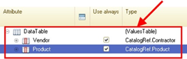
Fig. 348. Equivalent to programming code
After all the attributes planned to be created in the form are created, change the attribute list:
ChangeAttributes(AttributesToBeAdded, AttributesToBeDeleted);Execution of this code will cause the system to first remove the attributes listed in the AttributesToBeDeleted array, and then to add the attributes from the AttributesToBeAdded array. Then the form will be rebuilt.
When deleting attributes there is a loss of data they contain; however, if the attributes to be added and deleted have compatible kinds or the attribute to be added differs from an attribute to be deleted only by its properties (but not by kind), the data stored by an attribute will be saved.
After the attribute is added, it can be accessed in the program code only using the following construct: ThisObject.AttributeName. The ThisObject. expression is required for programmatically added attributes.
To change the composition or attribute properties, first get variable attributes. To do this, use the GetAttributes() method.
Pay attention to the two features of the acquired list:
-
This list is not dynamic and does not keep track of attribute changes that occurred after the method call.
-
Despite the fact that this list can be changed, these changes will not affect the real properties of the form attributes.
After the list of form attributes, we are interested in is received, any actions with the received attributes (for example, change the headings of all the attributes) can be performed and then the method of changing the details can be executed. Changing attributes should be done with prior deletion.
For example, if we want to change properties of the ParameterOrder attribute, then this should be done in the following way:
ArrayAttribute = GetAttributes("ParameterOrder");
... // Change the attribute
... AttributesToBeDeleted = NewMassive;
AttributesToBeDeleted.Add("ParameterOrder");
ChangeAttributes(ArrayAttribute, AttributesToBeDeleted);7.9.4.2. Changing command set
To manage a set of form commands, the ClientApplicationForm object has a special collection: Commands. With this collection, you can add, delete, and modify form commands.
So, to add the SetStatusCommand command with the Set status title, which will call the handler with the ProgramCommandHandler name, execute the following program code:
&AtServer
Procedure OnCreateAtServer(Cancel, StandardProcessing)
Command = Commands.Add("SetStatusCommand");
Command.Action = "ProgramCommandHandler";
Command.Title = "Set status";
EndProcedure
&AtClient
Procedure ProgramCommandHandler(Command)
...
EndProcedureThe command handler must exist in the form module and be preceded by the &AtClient compilation directive.
Note. Note. A single handler can serve several programmatically added commands.
7.9.4.3. Working with form items
After all necessary attributes and commands are created, you can add controls.
To manage form items, the ClientApplicationForm object has the Items collection, with which you can add, delete, and change properties of the form items and also move the form items between parents.
The Items collection provides access to a list of the form items that does not take into account the possible hierarchy of items. To work with the hierarchy, the object of the Items collection has the Parent and ChildItems properties.
The first property points to the form parent item, for example, for a field form located in a group, the Parent property will point to the form item of the FormGroup kind.
The ChildItems property exists for those form items that can have child items. For example, for the form item of the FormGroup kind, the ChildItems collection will contain those items that are located in this group.
To move an item from one collection to another (for example, from one group to another), use the Move() method. The parameters of this method describe the item to be moved, the new item parent and the form item before which the item to be moved is to be placed.
If the last parameter of the method is not specified, then the item to be moved will be placed at the end of the item collection of the new parent.
Note. Note. When programmatically changing the composition of the form items, you can call various event handlers associated with the activation of items (for example, the OnActivateRow event will be called for a table).
Let's take a closer look at how to add a control.
The example shows how to place two items on a form:
-
Form field associated with the form attribute
-
Button associated with the form command
&AtServer
Procedure OnCreateAtServer(Cancel, StandardProcessing)
MyAttributes = New Array;
TypeString = New TypeDescription("String", , New StringQualifiers());
MyAttributes.Add(New FormAttribute("ObjectDescription", TypeString, "", "Object description", False));
ChangeAttributes(MyAttributes);
Command = Commands.Add("ChangeRow");
Command.Action = "ProgramCommandHandler";
Command.Title = "Change row";
Item = Items.Add("ObjectDescription", Type("FormField"));
Item.Type = FormFieldType.InputField;
Item.DataPath = "ObjectDescription";
Item = Items.Add("ChangeRow", Type("FormButton"));
Item.CommandName = "ChangeRow";
EndProcedure
... &AtClient
Procedure ProgramCommandHandler(Command)
ThisObject.ObjectDescription = "Description of object formed
by a command";
EndProcedureThe form in which this code will be placed will look like in fig. 349. The form is displayed after the user has click ed the Edit row button.
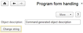
Fig. 349. Result of program modification of a form
7.9.5. Wait processing and form
Some operations may not be available in form item handlers or have undesirable consequences. This is evidenced by a special note in the handler description in the Syntax Assistant (see Specific features of using objects, their properties and methods). In these cases, you can apply a single idle handler (the AttachIdleHandler() method of the client application form) for a short period of time, for example, for 0.1 seconds. In this case, the handler stops, and no restrictions are imposed on the idle handler.
However, this scheme has a peculiarity. To understand this peculiarity, let's have a look at how the idle handler works. The operating system informs the application that the application is not performing any operations. At this moment, 1C:Enterprise checks that the time interval set for the idle handler has passed and calls the idle handler. The first consequence of this description is that control will be passed to the handler after a longer time interval than the application developer wanted. If, for example, after setting the idle handler there was a long execution of 1C:Enterprise language code, the idle handler will not be executed until the code execution is completed.
The second consequence of the description is that there might be situations when information from the operating system and the user action occur almost simultaneously. In this case, the idle handler will "interfere" with the standard sequence of calls and, for example, will implicitly violate the restriction imposed on a contextual server call or cause the form to be rebuilt. In this case, the normal operation of the user and the order of calling handlers will be disrupted, and the result will be unpredictable.
So, we recommend that you use idle handlers only when it is impossible to solve the required task in any other way. The developer must clearly understand what they are doing and why. Do not use the idle handler as a versatile way to implement any form manipulation that requires context server calls.
Let's consider an example of the described behavior. Imagine that the user edits the amount in the table of the order form. At this moment, the form attribute changes in the form idle handler: the current debt of the counterparty is calculated and displayed.
After calling the idle handler, since the attribute value is changed in it, the client application will set data for all form items. As a result, the text in the edited input field will "disappear", and the field will contain the value displayed before the user started editing the field.
To ensure that the text in the edited input field is not lost, in the idle handler, after changing the attribute values, call the RefreshDataRepresentation() form method, passing it a list of form items associated (directly or indirectly) with the changed form attribute(s) as a parameter. If there are no such items, pass an empty array as a parameter.
We do not recommend that you make context server calls that change form data in the idle handler if you think that the idle handler will conflict with the user input. In case of such conflict, the text in the edited input field will disappear.
Let's consider one more example. The form has an input field related to an attribute of the String type, for which a handler for changing the edit text is implemented. In this handler, among other things, a single idle handler is connected after a very short time interval (let it be 0.1 seconds). The idle handler performs an action that causes form items to be rebuilt, such as changing the visibility of the form item(s).
This example demonstrates another feature of the system behavior: when rebuilding form items, the text located in the input field is written to the form attribute. However, no handlers related to changing the value in the input field will be called. As a defense against such feature, you can only consider refactoring the algorithm (and the form code) so that all necessary actions on the form are performed after changes to the input field are completed and all related input field handlers are executed.
7.9.6. Working with a dynamic list
This section provides examples of performing some operations on working with a dynamic list placed in a form.
Note. Note. The examples below are not complete. They are intended to demonstrate various techniques of handling a dynamic list.
7.9.6.1. Dynamic list query parameter
This section provides an example of setting a dynamic list query parameter.
Suppose the following data query is specified for a dynamic list:
SELECT
Goods.Code AS
Code, Goods.Description
AS Description, Goods.SKU AS
SKU, InventoryBalance.CountBalance
AS Count, PricesGoodsSliceLast.Price
AS Price, Goods.IsFolder
FROM
Catalog.Goods
AS Goods
LEFT JOIN
AccumulationRegister.GoodsInventory.Balance(, Warehouse = &Warehouse) AS
GoodsInventoryBalances
BY
(InventoryBalance.Product = Goods.Ref)
LEFT JOIN
InformationRegister.GoodsPrices.SliceLast(, PriceType = &PriceType) AS
GoodsPricesSliceLast
BY Goods.Ref
= PricesGoodsSliceLast.ProductThen, to set the parameters of this query (in the OnCreateAtServer() handler), specify the Warehouse and PriceType parameters as follows.
// GoodsList is a form attribute of the DynamicList
type
// Parameters.Warehouse and Parameters.PriceType -
form parameters of the corresponding types
&AtServer
Procedure OnCreateAtServer(Cancel, StandardProcessing)
GoodsList.Parameters.SetParameterValue("Warehouse", Parameters.Warehouse);
GoodsList.Parameters.SetParameterValue("PriceType", Parameters.PriceType);
EndProcedure7.9.6.2. Filter
This section provides examples of setting and removing a filter in a dynamic list.
Set
The function adds a filter to the dynamic list and returns the created filter item.
Function AddFilter(FiltersList, FieldName, Value, ComparisonType = Undefined, Use = True)
NewItem = FiltersList.Items.Add(Type("DataCompositionFilterItem"));
NewItem.LeftValue = New DataCompositionField(FieldName);
NewItem.ComparisonType = ?(ComparisonType = Undefined, DataCompositionComparisonType.Equal, ComparisonType);
NewItem.RightValue = Value;
NewItem.Use = Use;
Return NewItem;
EndFunctionExample:
// DynamicList is a
form attribute of the DynamicList type
// The list must
contain the "Counterparty" column
//
// Filter by the
"Counterparty" field is set, filter value
// is in the
"CounterpartyRef" variable, filter is enabled, // filter condition of
selection is "equal". AddFilter(DynamicList.SettingsComposer.FixedSettings.Filter, "Counterparty", CounterpartyRef);Delete
The procedure removes a dynamic list filter and returns the result of the deletion. If the name of the field with the filter to be deleted is not specified, the filter list is cleared.
Function DeleteFilter(FiltersList,FieldName = "")
If IsBlankString(FieldName) Then
FiltersList.Items.Clear();
Return True;
EndIf;
Field = New DataCompositionField(FieldName);
FilterDeleted = False;
For Each FilterItem In FiltersList.Items Do
If FilterItem.Use AND FilterItem.LeftValue = Field Then
FiltersList.Items.Delete(FilterItem);
FilterDeleted = True;
EndIf;
EndDo;
Return FilterDeleted;
EndFunctionExample:
// DynamicList is a
form attribute of the DynamicList type
// The list must contain the
"Counterparty" column
// Filter by the
"Counterparty" field is deleted. Result = DeleteFilter(DynamicList.SettingsComposer.FixedSettings.Filter, "Counterparty");7.9.6.3. Grouping
This section contains examples of setting and deleting groups in a dynamic list.
Setting
The function adds a grouping to the dynamic list and returns the created grouping item.
Function AddGroup(GroupsList, FieldName, Use = True, GroupType = Undefined)
Field = New DataCompositionField(FieldName);
NewItem = GroupingsList.Items.Add(Type("DataCompositionGroupField"));
NewItem.Use = Use;
NewItem.Field = Field;
NewItem.GroupType = ?(GroupType = Undefined, DataCompositionGroupType.Items, GroupType);
Return NewItem;
EndFunctionExample:
// DynamicList is a
form attribute of the DynamicList type
// The list must
contain the "Counterparty" column
//
// Grouping by the
"Counterparty" field is created, created
// grouping will be
used, grouping kind is "items only"
Grouping = List.SettingsComposer.Settings.Structure.Add(Kind("DataCompositionGroup"));
AddGroup(Group.GroupFields, "Counterparty");Delete
The procedure removes a dynamic list grouping and returns the result of the deletion. If the name of the field with the grouping to be deleted is not specified, the grouping list is cleared.
Function DeleteGrouping(GroupingsList, FieldName = "");
If IsBlankString(FieldName) Then
GroupingsList.Items.Clear();
Return True;
EndIf;
Field = New DataCompositionField(FieldName);
GroupingDeleted = False;
ArrayItemsForDeletion = New Array;
For Each GroupingItem from GroupingsList.Items Do
If GroupingItem.Field = Field Then
ArrayItemsForDeletion.Add(GroupingItem);
EndIf;
EndDo;
For Each ItemToRemove In ArrayItemsForDeletion Do
GroupingsList.Items.Delete(DeletingItem);
GroupingDeleted = True;
EndDo;
Return GroupingDeleted;
EndFunctionExample:
// DynamicList is a
form attribute of the DynamicList type
//
// delete all groupings
in the dynamic list
Result = DeleteGrouping(DynamicList.SettingsComposer.FixedSettings.Grouping);7.9.6.4. Order (sorting)
This section provides examples of setting and removing dynamic list ordering.
Setting
The function adds a sort field to the dynamic list and returns the created order item.
Function AddOrder(OrderList, FieldName, Use = True, OrderType = Undefined)
Field = New DataCompositionField(Field);
NewItem = OrderList.Items.Add(Type("DataCompositionOrderItem"));
NewItem.Use = Use;
NewItem.Field = Field;
NewItem.OrderType = ?(OrderType = Undefined, DataCompositionSortDirection.Vozr, OrderType);
Return NewItem;
EndFunctionExample:
// DynamicList is a
form attribute of the DynamicList type
// The list must
contain the "Description" column
//
// Sorting is performed
by the "Description" field, // sort direction is
descending, sort is used
AddOrder(DynamicList.SettingsComposer.Settings.Order, "Description", True, DataCompositionSortDirection.Desc);Delete
The procedure removes a dynamic list sort and returns the result of the deletion. If no ordering field name is specified, the ordering list is cleared.
&AtClient
Function DeleteSorting(SortingList, FieldName = "")
If IsBlankString(FieldName) Then
SortingList.Items.Clear();
Return True;
EndIf;
Field = New DataCompositionField(FieldName);
OrderDeleted = False;
ArrayItemsForDeletion = New Array;
For Each OrderItem In OrderList.Items Do
If OrderItem.Field = Field Then
ArrayItemsForDeletion.Add(OrderItem);
EndIf;
EndDo;
For Each ItemToRemove In ArrayItemsForDeletion Do
OrderList.Items.Delete(DeletingItem);
OrderDeleted = True;
EndDo;
Return OrderDeleted;
EndFunctionExample:
// DynamicList is a
form attribute of the DynamicList type
//
// Ordering by the
"Description" field is deleted (not disabled)
Result = DeleteOrder(DynamicList.SettingsComposer.FixedSettings. Order, "Description");7.9.6.5. Conditional appearance
This section contains examples of specifying conditional appearance of the dynamic list. The conditional appearance uses the List dynamic list that contains the Organization and Sum fields (of the Number type). In the example, there are three conditional appearance items set:
-
If the value of the Sum field is less than 500, then the text of the Organization and Sum fields is displayed in red.
-
If the value of the Sum field is more than 500 but less than 10 000, then the text for all fields of the row is displayed in blue.
-
If the value of the Sum field is greater than 10,000, then the text of the Organization and Sum fields is displayed in green.
Function SetConditionalAppearance(AppearanceList, AppearanceFieldsNames, StructureAppearance, Use = True) Export
NewItem = AppearanceList.Items.Add();
NewItem.Use = Use;
// Define appearance fields defined by an array with field names
For Each FieldName In AppearanceFieldsNames Do
AppearanceField = NewItem.Fields.Items.Add();
AppearanceField.Use = True;
AppearanceField.Field = New DataCompositionField(FieldName);
EndDo;
// Set the appearance set by the structure,
// where Key is the appearance parameter name,
// and Value is the appearance
parameter value
For Each AppearanceItem In StructureAppearance Do
NewItem.Appearance.SetParameterValue(AppearanceItem.Key, AppearanceItem.Value);
EndDo;
Return NewItem;
EndFunctionExample of setting conditional appearance:
ConditionalAppearanceItems = List.SettingsComposer.FixedSettings.ConditionalAppearance;
AppearanceFields = New Array;
AppearanceFields.Add("Sum");
AppearanceFields.Add("Organization");
// ***** Set a red
color for the sum less than 500
Appearance = New Structure;
Appearance.Insert("TextColor", New Color(128,0,0));
NewItem = SetConditionalAppearance(ConditionalAppearanceItems, AppearanceFields, Appearance);
// Set an appearance
condition: Sum < 500
AddFilter(NewItem.Fulter, "Sum", 500, DataCompositionComparisonType.Less);
// ***** Set a green
color for the sum more than 10 000
Appearance = New Structure;
Appearance.Insert("TextColor", New Color(0,128,0));
NewItem = SetConditionalAppearance(ConditionalAppearanceItems, AppearanceFields, Appearance);
Set an appearance
condition: Sum > 10 000
AddFilter(NewItem.Filter,"Sum", 10000, DataCompositionComparisonType.Greater);
// set the blue color
if the sum is in the range from 500 to 10 000
Appearance = New Structure;
Appearance.Insert("TextColor", New Color(0,0,128));
// Pass an empty array
as a list of formatted fields
// indicates appearance
of all fields in a row
NewItem = SetConditionalAppearance(ConditionalAppearanceItems, New Array, Appearance);
// Create a group of
conditions "AND"
FiltersGroup = NewItem.Filter.Items.Add(Type("DataCompositionFilterItemGroup"));
FiltersGroup.GroupType
= DataCompositionFilterItemsGroupType.AndGroup;
// Set an appearance
condition: Sum > 500 AND Sum < 10 000
AddFilter(FiltersGroup, "Sum", 500, DataCompositionComparisonType.Greater);
AddFilter(FiltersGroup, "Sum", 10000, DataCompositionComparisonType.Less);7.9.7. Drag and drop feature
1C:Enterprise supports drag and drop. Use it to transfer data between different form items. For example, you can transfer catalog list items from one group to another, transfer data from a table field to a spreadsheet document field, or transfer a list of selected files from a client operating system file tool to a form item.
Drag and drop operations support the following form items:
-
Form table
-
Spreadsheet document field
-
Calendar field
-
Picture field
-
Image decoration
-
Planner field
When dragging, the following terms are used:
-
Data source. The form item from which data can be transferred.
-
Data destination. The form item into which data can be transferred.
You can enable or disable the possibility to send or receive data for controls. For this, the form items have the following properties:
-
Enable start dragging. Allows the form item to provide data.
-
Enable dragging. Allows the form item to accept data. These properties can be set from the property palette or from 1C:Enterprise language.
When the mouse is clicked on the selected area of the control being the data source, the DragStart event handler is called. If a drag source is the planner field, then the DragStart event occurs when the mouse cursor moves out of this field. As the parameters of this event, objects of the DragParameters and Execute types are passed. The DragParameters parameter have the following properties:
-
Value. Contains a value to be dragged. For example, for a managed form table, it can be an object reference. For a spreadsheet document, it can be a spreadsheet document area. For a calendar, it can be a date. This property can be assigned its value (for example, some structure), then this value will be an object to be dragged. For a managed form table associated with a form attribute of the FormDataCollection, FormDataTree, or FormDataStructureWithCollection type, the following objects are passed as a dragging value:
-
Row ID (or ID array) if the drag and drop is within one table.
-
Collection item (or item array) if the drag and drop is between different tables.
-
When you perform a drag and drop operation from the planner field (see Planner), the Value property contains copies of the items to be dragged.
-
Action. Indicates a drag and drop action and is a value of the DragAction type.
-
AllowedActions. Indicates the allowed drag and drop actions and is a value of the DragAllowedActions type. Using this property, you can specify which operations are possible with data source data (for example, copy only).
The Execute parameter allows you to enable or disable standard processing of a drag and drop operation from this control. For the DragStart event, the standard processing is the start of data dragging.
Next, the DragCheck event handler is called for the form item being the data destination. This handler is called whenever the cursor hits a new object in the form item being the data destination (for example, in a new table cell or a spreadsheet document field when it hits a new date in the calendar field). The set of parameters for this event depends on the form item being the data destination, but the first two parameters are the same for all. These are the objects of the DragParameters and StandardProcessing types. The remaining parameters describe an object under cursor. When processing this event, you can control the kind of the cursor, that is, for example, indicate that dragging into this control is prohibited or only copying is possible. To do this, set the required action in the Action property of the DragParameters parameter. Keep in mind that the dragging action to be set must be allowed, that is, it must not conflict with the value of the AllowedActions property. For example, the Copy action does not conflict with the CopyAndMove value of the allowed actions, and the Move value is in conflict with the Copy value of the allowed actions. The StandardProcessing parameter is used to indicate whether standard processing by the form item of this event is possible. The standard drag and drop processing depends on the control:
- For a table, a possibility of inserting a value is checked, that is, a kind of value is checked and if it matches the type of displayed data, the standard actions are performed. Standard actions for hierarchical dynamic lists are moving to a group. For tables displaying record sets or tables, these are changing the order of rows and copying.
If the ChangeRowOrder table property is set to False, then when dragging inside the table, standard processing cancels the drag and the Drag event will not be called.
If the ChangeRowOrder property is set to True or the dragging is from outside the table, standard processing will not cancel the drag.
Standard processing does not cancel dragging if the table has the SelectionMode property set to Multiple, the ChangeRowOrder property set to True, or the dragging is from outside the table and more than one item is dragged.
-
For a table displaying a tree, the standard drag processing is as follows:
-
When dragging tree items inside one node, the order of the tree items inside the node is changed.
-
When dragging tree items between different nodes, the tree items are moved to the selected node.
-
-
For a spreadsheet document field, it is checked whether the passed value can be inserted.
-
There is no standard processing for a picture field and calendar.
-
When dragging files, the standard action will be an attempt to open the files involved in the drag and drop operation.
If you release the mouse button in the form item being the data destination, the Drag event handler is called. The parameter set for this event is the same as for the DragCheck event. The StandardProcessing parameter allows you to enable or disable standard event processing by the form item. The standard drag and drop actions are described above.
Then, in the control being the data source, the DragEnd event handler is called. When processing this event, the form item being the data destination can, for example, delete the moved data or clear some variables.
For some form items (form table, picture field, picture decoration), you can specify how the system will behave when trying to drag files onto these form items. To specify the behavior, use the File dragging mode property:
-
As file. In this case, an object of the File type (or an array of such objects) will be the drag value. This dragging mode is not supported when using the web client.
-
As file reference. In this case, an object of the FileRef type (or an array of such objects) will be the drag value. This dragging mode is supported for both the thin client and the web client.
If for the form item, the file dragging mode is set to As file reference, then:
-
In the web client, the DragCheck event handler occurs once, when the mouse button is released and just before executing the Drag event handler.
-
In the thin client, the DragCheck event handler occurs multiple times during dragging.
If the file dragging mode for the form item is set to As file, then the web client ignores dragging and the DragCheck and Drag event handlers are not executed.
Let's take a closer look at the FileRef object. It is the special object enabling the consistent file operation in different environments, and it contains some key data about the selected file. At this, you should understand that, for instance, the web client operation is prone to more limitations if compared with the thin client. Such limitations explain the following features of objects of FileRef type:
-
These objects may not be serialized.
-
As a result of the previous paragraph, these objects may not be stored in the form attributes, in the infobase data and be passed between the client and the server.
-
The FileRef object cannot be created from 1C:Enterprise language. It can be created only by the platform during the drag mechanism operation.
At the same time, data structures located in RAM (arrays, structures, maps, and so on) may well store objects of the FileRef type.
Moreover, consider the fact that the link to the file secures presence of the file on the hard drive only immediately after it is generated in the platform. At this, the FileRef object does not enable you to check whether the file that the object refers to exists and is located at the same place. Thus, objects of the FileRef type are recommended to be used immediately after they are received. However, if you still need storing such objects before their actual use, you should do it using the client variables of the form where you operate the files.
7.9.8. Different approaches to modality
7.9.8.1. General information
In applications developed using 1C:Enterprise, it often becomes necessary to open a form that will provide several options at the same time:
-
Block work with other fragments of the application interface.
-
Allow you to enter any information (including an answer to the question).
-
Stop execution of the application code until work with the open form is completed.
At the same time, the forms in consideration can be created by an application developer in the 1C:Enterprise language and be part of the platform itself (for example, forms that open the Warning(), Question(), etc. methods).
Within 1C:Enterprise, there are two schemes for using such forms:
-
Modal windows
-
Blocking windows
Within a single application, either one approach or a mixed model can be used. To control this possibility, use the Modality usage mode configuration property (see Specifying compatibility properties).
The first modality mode (modal windows) involves synchronous calls in 1C:Enterprise language (see General information) and special operating system windows, which are modal windows. Modal windows can be opened using the OpenFormModal() or Warning () method. However, modal windows are not supported in web client.
In such cases, it is recommended that you use asynchronous calls (for more information, see General information) and blocking windows instead. To use asynchronous calls, used algorithms must be significantly modified. You can use different asynchronous modes: via callbacks or promises.
In different situations, one or the other mode is preferable. Let us review both options. For example, there is an algorithm that asks the user a question and, depending on the answer, executes one of application code branches.
Example with modal windows:
&AtClient
Procedure ExecuteAlgorithm()
Result = Question("Execute quickly or not slowly?", QuestionDialogMode.YesNo);
If Result = DialogReturnCode.Yes Then
// First
version of an algorithm
Else
// Second
version of an algorithm
EndIf;
EndProcedureIn this example (modal windows), a work of the 1C:Enterprise language will stop at the Result = Question() row and will continue only after a user answers the question.
Example with blocking windows:
&AtClient
Async Procedure ExecuteAlgorithm(Command)
Result = Await
DoQueryBoxAsync("Execute quickly or not slowly?", QuestionDialogMode.YesNo);
If Result = DialogReturnCode.Yes Then
// First
version of an algorithm
Else
// Second
version of an algorithm
EndIf;
EndProcedureFor more information on how the asynchronous code with promises works, see How it works.
Callbacks will be useful if you need to open a form and then process its closing. For example, you open a form from the common ClientOperation module. The form to be opened is the common AppearanceAssistant form.
The common module will contain the following program code:
Procedure OpenAssistantForm() Export
ClosingCallback
= New NotifyDescription("FormClosingProcessing", ThisObject);
OpenForm("CommonForm.AppearanceAssistant", , , , , , ClosingCallback, FormWindowOpeningMode.LockOwnerWindow);
EndProcedure
Procedure FormClosingProcessing(ClosingResult, AdditionalParameters) Export
Message("The
form is closed: " + ClosingResult);
EndProcedureYou can leave the form module blank if you just need to close the form. If the form to be closed must send some operation result, create a special button in the form that will call the Close() form method and pass data to process in the close handler as a parameter of this method. In the close notification handler, this data will be available as a parameter of the ClosingResult handler. The close button click handler can look as follows:
&AtClient
Procedure CloseForm(Command)
Close("Result");
EndProcedure7.9.8.2. Closing an auxiliary or main application window and blocking windows
You can close a form in two work scenarios: when a single form is closed and when the entire application is closed (the main application window is closed). In order to separate these scenarios, the system implements a separate process of processing the closure of the entire application. To indicate that the form is closed during the closing of the entire application, the Exit parameter is implemented in the BeforeClose and OnClose event handlers. In addition, in BeforeClose form event handler and the BeforeExit event handler of the managed application module, the MessageText parameter is implemented. Let's consider these parameters in greater detail:
-
Exit. This parameter is set by the system to True if the user tries to close the main application window (if this parameter exists for the selected handler). When closing one form, this parameter will be set to False.
-
MessageText. This parameter must be generated in the event handler (if this parameter exists for the selected handler).
Let's take a closer look at how these parameters work together when the application closes. Code in the 1C:Enterprise language that processes closure of the form with specified features will be, as follows:
&AtClient
Var AnswerBeforeClosing;
&AtClient
Procedure BeforeClose(Cancel, Exit, MessageText, StandardProcessing)
If Not Exit Then
If AnswerBeforeClosing <> True Then
Cancel = True;
Callback = New NotifyDescription("BeforeClosingCompletion", ThisObject);
ShowQueryBox(Callback, "Close form?", QuestionDialogMode.YesNo);
EndIf;
Else
Cancel = True;
MessageText = "When the form is closed, all data will be lost. You intend";
EndIf;
EndProcedure
&AtClient
Procedure BeforeClosingCompletion(Result, AdditionalParameters) Export
If Result = DialogReturnCode.Yes Then
AnswerBeforeClosing
= True;
Close();
Else
AnswerBeforeClosing
= Undefined;
EndIf;
EndProcedureIn the example given, a special reaction is implemented on closing the entire application. Processing the process of closing an application works, as follows:
-
If a form is closed when the user exits the application, the application developer can detect it by the Exit parameter state. The developer also decides whether any message must be displayed to the user giving them a choice: exit the application or continue working since the form to be closed contains important information.
-
If the developer believes that a message needs to be issued to the user, then they can do it using the MessageText parameter of BeforeClose or BeforeExit event handler. The Cancel parameter should also be set to True.
-
If at least one form or procedure of the BeforeExit event handler reports that it "does not want" to close the application, the system will produce dialog boxes that require user response. The number of dialog boxes is equal to the number of close failures (including the managed application module handler). The web client will display a single dialog box that will contain all the messages that were set in the managed forms and the managed application module. At the same time, in Mozilla Firefox, the dialog box will contain only the text set by the web browser itself, while the text set in the 1C:Enterprise event handlers will not be displayed.
-
In the thin client, the dialog box will display the warning text set by the developer, and the Exit and Continue buttons. If Exit is selected in all dialog boxes, the application will be terminated. If Continue is selected in at least in one dialog box, the application will not be completed and work will continue. If you refuse to complete the work, the form in which the Continue button was pressed will remain on the screen.
If the Exitparameter is set to False, this means that a single form is closed, and in this case the logic of operation is as follows:
-
First, a question is asked about the necessity (possibility) of closing a form and the actual closing of a form is canceled.
-
After a user has answered the question, it is noted in the special client variable that the "real" closure of a form will now be performed and it will be closed again.
When processing closing of the application (the Exit parameter is set to True), in the BeforeClose, OnClose, BeforeExit, and OnExit handlers, any server calls and opening any forms are prohibited. This leads to a recommendation to store in the form's data only information that may be needed to determine whether a form can be closed at closing the application's work or not. For existing forms, it may be necessary to reprocess the mechanisms responsible for closure.
Therefore, a dialog box with the Exit and Continue buttons is displayed if, upon leaving the BeforeClose processor, its Exit and Cancel parameters are set to True. In this case, the dialog box will display the text that is set in the MessageText parameter. If the MessageText parameter is not set, then An operation is in progress will be shown in the dialog box as warning text.
Similar behavior will be observed if the Cancel parameter in the BeforeExit handler is set to True.
In all other cases, it is considered that there are no reasons preventing closure of forms and application.
7.9.8.3. Using blocking windows
The platform provides a number of auxiliary objects that you can use to perform uniform actions. The action uniformity is ensured by the fact that the dialogs for these actions are provided by the platform. This means that the user does not have to get used to a new interface every time to perform certain actions.
Naming of methods to open dialog boxes for such objects is standard for the platform:
-
Synchronous method (if any). Open(), Select(), and so on.
-
Asynchronous method (using callback). Show().
-
Asynchronous method (using promises). OpenAsync(), ChooseAsync(), and so on.
Chapter 8. Working with queries
8.1. General information
To form and execute queries to database tables, the special Query object in the system is used. A query is convenient to use when there is a need to get a complex selection of data grouped and sorted, as needed. One of classic examples of its use is a summary of the register of record's state at a certain point in time. Besides, the query feature allows you to easily receive information in different time sections.
8.2. Query data (table) sources
Sources of data for query language data are database tables. Tables are divided into two main classes: real and virtual.
Real tables are stored in a database, that is, they are interpreted from a real database table. In case of a real table, there may be present the calculable fields whose values are calculated as function of several real fields.
Virtual tables are not stored in database. When accessing information from virtual tables, the system automatically collects information from real database tables to execute a query. A virtual table can be parameterized, that is, the actual content of a virtual table can be determined by the values of parameters the actual values of which are specified in the query text. For each virtual table, a name is defined that is used in queries to identify a table.
A table name can be set in English and Russian. For example, Catalog.Goods. Names of tables and fields cannot match query language keywords.
A separate table subclass is formed by the so-called object tables. An actual database table is always used as an object table. The difference of object tables from other tables is explained in their name. Object tables are used to store states of 1C:Enterprise application objects, such as catalogs, documents, and so on. Each object table corresponds to 1C:Enterprise application object type. For example, different tables will correspond to Catalog.Goods objects and Catalog.Counterparties objects. Each object table record stores the state of an object of the respective type. Each object table has a field of the Reference type for the current record. Besides, object tables have a method for getting a custom object presentation from record fields.
Object tables can also be hierarchical tables. For hierarchical tables, the Parent field is defined. It contains a reference to the record that the current record is subordinate to according to the hierarchy.
A table field can be either a table field or a nested table. The main difference between a standard field and a nested table is that within one record, a single field corresponds to a single value while a nested table corresponds to a value of the QueryResult type with the pre-set array of columns. An example of a nested table is a document or catalog table.
A table field value type can be a value of the NULL type. Such values are contained in the table record fields for which this field is not defined or does not make sense. For example, values of this type are contained in catalog group records by fields that can have values only for items of this catalog.
8.3. Virtual and standard fields
A standard field is a field formed from data that is stored in a DBMS and can be additionally processed by DBMS tools. A virtual field is a field formed from data that is stored in a DBMS but additionally processed by 1C:Enterprise server tools (including in file mode). The following fields in query tables are virtual:
-
Presentation fields obtained using either the Presentation field of the respective table or the query language function.
-
DataVersion
-
PredefinedDataName
-
PointInTime
-
ValueType for the table of the chart of characteristic types
-
Kind for the table of the chart of accounts
-
Type for the document journal table
-
RecordType for the accounting register table
-
RecordType for the accumulation register table
-
Any fields with values of the following types: ValueStorage, UUID and an external data source reference
Virtual fields have the following features:
-
Not all virtual fields can be converted "back" to the value stored in the DBMS. These are presentation fields and the ValueType field for the table of the chart of characteristic types.
-
Not all virtual fields with the same name can be compared with each other if they are obtained from different tables. These are the DataVersion, PredefinedDataName, PointInTime, and Type fields of the document journal table.
-
If a system enumeration value (a reference to the external data source table or a UUID) is obtained in the query field and the resulting value is not combined with other types, the field values are grouped regardless of which tables the value is obtained from when you use the GROUP BY operation in the query.
-
Virtual fields of the string type do not support string operations and comparison with data of the String type.
8.4. Query language
8.4.1. General information
As described above, to execute a query, you need to create a query text. A query text is an instruction on how to execute a query. A query text describes which information database tables are used as query data sources, table fields that must be processed in a query, grouping rules, result sorting rules, and so on.
An instruction is compiled in a special language (query language) and consists of sections, clauses, words, functions, and comments. In this chapter, you can read about the purpose and usage methods for all syntactic structures of the query language.
8.4.2. Query language syntax diagram
In this chapter, you can read about the query language syntax described with a set of rules. Each rule describes one syntactic structure.
Each language construct can contain keywords, separators (dots, commas, round brackets), and other constructs.
<Syntactic structure>
THIS_KEYWORD
<This_language_construct>, <This_language_construct>
THIS_FUNCTION
(<This_language_construct>)In the rules describing the query language, syntactic structures are specified in angle brackets. Keywords and function names are described in capital letters.
Syntactic structures can contain optional items, for example, keywords. In the rules describing the query language, optional items are enclosed in square brackets.
[THIS_OPTIONAL_WORD]
[<This_optional_construct>]In some cases, one of several alternative items can be used in a syntactic structure. Such items in the rules are listed separated with a vertical bar.
EITHER_THIS_WORD |
OR_THIS_WORD
<Either_this_construct>
| <Or_this_construct>The descriptions of all structures are accompanied by examples explaining the procedure for their use in the query language.
8.4.3. Comments in query language
A query text can contain comments. A comment is a line part that begins with a sequence of characters // and extends to the end of the line.
// This is a commentWhen executing the query, comments are ignored.
Note. Note. A query designer removes comments from a text.
8.4.4. Using predefined configuration data
A query text can contain predefined configuration data, such as:
-
Enumeration values
-
Predefined data of the following objects:
-
Catalogs
-
Charts of characteristic types
-
Charts of accounts
-
Charts of calculation types
-
-
Empty references
-
Values of business process route points
A query text can also contain system enumeration values that can be assigned to fields in database tables: AccumulationRecordType, AccountType, and AccountingRecordType.
Predefined configuration data and system enumeration values are queried using a literal of a functional type.
Value(<ValuePresentation>)For system enumerations, a value presentation looks as follows:
<SystemEnumerationName>.<Value>Valid system enumeration names are given above. For the list of valid values for each system enumeration, see its description.
For predefined configuration data, a value presentation looks as follows:
<PredefinedValueType>.<MetadataObjectName>.<Value>A predefined value type can be:
-
Catalog
-
ChartOfCharacteristicTypes
-
ChartOfAccounts
-
ChartOfCalculationTypes
-
Enum
A metadata object name is specified as it is defined in Designer.
For enumerations defined in the configuration, a value is a name of the respective metadata object of the EnumerationValue type. For all other predefined value types, a value is a predefined data item name as it is specified in Designer or EmptyRef to specify an empty reference.
For business process route points, a value presentation looks as follows:
BusinessProcess.<MetadataObjectName>.RoutePoint.<RoutePointName>Below you can see a few query fragments that explain how to use predefined data in queries.
WHERE City = Value(Catalog.Cities.Washington)
WHERE City = Value(Catalog.Cities.EmptyRef)
WHERE ProductType = Value(Enumeration.ProductKinds.Service)
WHERE RecordType = Value(AccumulationRecordType.Receipt)
WHERE RoutePoint = Value(BusinessProcess.Agreement. RoutePoint.Consent)8.4.5. Bilingual keyword presentation
A significant feature of 1C:Enterprise query language is that, as in 1C:Enterprise language, all keywords have equivalents in two languages: English and Russian. Below in this chapter, you can learn how to write keywords in Russian. The table below shows Russian and English equivalents for query language keywords.
| Russian | English |
|---|---|
| АВТОУПОРЯДОЧИВАНИЕ | AUTOORDER |
| БУЛЕВО | BOOLEAN |
| В | IN |
| ВНЕШНЕЕ | OUTER |
| ВНУТРЕННЕЕ | INNER |
| ВОЗР | ASC |
| ВСЕ | ALL |
| ВЫБОР | CASE |
| ВЫБРАТЬ | SELECT |
| ВЫРАЗИТЬ | CAST |
| ГДЕ | WHERE |
| ГОД | YEAR |
| ГРУППИРУЮЩИМ | GROUPING |
| ДАТА | DATE |
| ДАТАВРЕМЯ | DATETIME |
| ДЕКАДА | TENDAYS |
| ДЕНЬ | DAY |
| ДЕНЬГОДА | DAYOFYEAR |
| ДЕНЬНЕДЕЛИ | WEEKDAY |
| ДЛЯ | FOR |
| ДОБАВИТЬ | ADD |
| ДОБАВИТЬКДАТЕ | DATEADD |
| ЕСТЬ | IS |
| ЕСТЬNULL | ISNULL |
| ЗНАЧЕНИЕ | VALUE |
| И | AND |
| ИЕРАРХИЯ | HIERARCHY |
| ИЗ | FROM |
| ИЗМЕНЕНИЯ | UPDATE |
| ИЛИ | OR |
| ИМЕЮЩИЕ | HAVING |
| ИНАЧЕ | ELSE |
| ИНДЕКСИРОВАТЬ | INDEX |
| ИСТИНА | TRUE |
| ИТОГИ | TOTALS |
| КАК | AS |
| КВАРТАЛ | QUARTER |
| КОГДА | WHEN |
| КОЛИЧЕСТВО | COUNT |
| КОНЕЦ | END |
| КОНЕЦПЕРИОДА | ENDOFPERIOD |
| ЛЕВОЕ | LEFT |
| ЛОЖЬ | FALSE |
| МАКСИМУМ | MAX |
| МЕЖДУ | BETWEEN |
| МЕСЯЦ | MONTH |
| МИНИМУМ | MIN |
| МИНУТА | MINUTE |
| НАБОРАМ | SETS |
| НАЧАЛОПЕРИОДА | BEGINOFPERIOD |
| НЕ | NOT |
| НЕДЕЛЯ | WEEK |
| НЕОПРЕДЕЛЕНО | UNDEFINED |
| ОБЩИЕ | OVERALL |
| ОБЪЕДИНИТЬ | UNION |
| ПЕРВЫЕ | TOP |
| ПЕРИОДАМИ | PERIODS |
| ПО | BY or ON |
| ПОДОБНО | LIKE |
| ПОДСТРОКА | SUBSTRING |
| ПОЛНОЕ | FULL |
| ПОЛУГОДИЕ | HALFYEAR |
| ПОМЕСТИТЬ | INTO |
| ПРАВОЕ | RIGHT |
| ПРЕДСТАВЛЕНИЕ | PRESENTATION |
| ПУСТАЯТАБЛИЦА | EMPTYTABLE |
| РАЗЛИЧНЫЕ | DISTINCT |
| РАЗРЕШЕННЫЕ | ALLOWED |
| СГРУППИРОВАТЬ | GROUP |
| СЕКУНДА | SECOND |
| СЕКУНДА | SECOND |
| СОЕДИНЕНИЕ | JOIN |
| СПЕЦСИМВОЛ | ESCAPE |
| СРЕДНЕЕ | AVG |
| ССЫЛКА | REFS |
| СТРОКА | STRING |
| СУММА | SUM |
| ТИП | TYPE |
| ТИПЗНАЧЕНИЯ | VALUETYPE |
| ТОГДА | THEN |
| ТОЛЬКО | ONLY |
| УБЫВ | DESC |
| УНИКАЛЬНО | UNIQUE |
| УНИЧТОЖИТЬ | DROP |
| УПОРЯДОЧИТЬ | ORDER |
| ЧАС | HOUR |
| ЧИСЛО | NUMBER |
Note. Note. The keywords are not case-sensitive.
8.4.6. Main query text sections
A query text can be described by the following rule:
<Query Text>
<Query
description>
[<Merge queries>]
[<Order results>]
[AUTOORDER]
[<Totals
description>]As can be seen from this rule, the query text consists of several parts or sections:
-
<Query description>. It is the only required section in the query text. In many cases, it is enough to specify only this section. The section defines query data sources, selection fields, groupings, and so on. This section is described by a whole set of rules and reviewed below.
-
<Merge queries>. The query language allows merging multiple query results. For the query merging description, see Merging queries.
-
<Order results>. In this section, you can define conditions for ordering strings in a query result. For query result ordering, see Ordering of query results.
-
AUTOORDER. In this section, you can enable the mode to order strings in a query result automatically. For the description of this mode, see Auto-ordering results.
-
<Totals description>. In this section, you can specify which totals must be calculated in a query. For the description of this section, see Calculating query totals.
8.4.7. Query description
8.4.7.1. General information
A query text must contain a query description section, which defines:
-
Fields that will be contained in a query result.
-
Query data sources, that is, source tables.
-
Conditions affecting data selection in a query.
-
Query result grouping order.
The query description section consists of several interrelated clauses:
<Query description>
SELECT [ALLOWED] [DISTINCT] [TOP <Count>]
<Selection
field list>
[INTO|ADD <Table name>]
[FROM ]
[INDEX BY [SETS] <Field list>]
[WHERE <Filter condition>]
[GROUP BY <Grouping fields>]
[HAVING <Filter condition>]
[FOR UPDATE [<Top level table list>]]A query description begins with the required SELECT keyword.
The ALLOWED keyword means that a query will select only those entries to which the current user has rights. If this word is not specified, the query will be completed with an error when it selects records to which the user does not have rights. This keyword can be specified only in the top-level SELECT clause and applies to the entire query including nested queries. Note that theALLOWED keyword affects the operation only if tables have data access restrictions (see Data access restriction). Access rights to the table are not considered when using the ALLOWED keyword. For example, if a table does not have the READ right, a query using such table will be executed with an error regardless of whether the ALLOWED keyword is used in the query.
Use the DISTINCT keyword to specify that duplicate strings cannot be included in the result.
The TOP <Count> construct sets a limit on the number of strings in a query result. The very first (according to the rules for ordering query results) strings will be selected. The number of results is specified as an integer. In the query language, you can order in nested queries if a nested query contains the TOP construct.
The <Selection field list> section describes fields that must be contained in a query result.
The FROM clause specifies data sources, which are infobase tables processed in the query. The source description can be omitted only if they are completely defined in the selection field list. For rules of describing query data sources, see Query source description.
The INTO, ADD, INDEX BY, and INDEX BY SETS clauses are related to temporary table operations. For more information, see Temporary table.
The WHERE <Filter condition> clause allows filtering a query result. Only records for which the specified condition is True are included in a result. For the filter condition description rules, see Filtering query results.
The GROUP clause allows describing the query result grouping order (see Grouping query results).
The HAVING clause allows setting conditions to grouping results (see Conditions for aggregate function values).
The FOR UPDATE clause indicates that data read in a transaction must be locked. The read data becomes unavailable for reading in other sessions. In file mode, specified tables are locked. In client/server mode, only selected records are locked. The lock is released after the transaction is completed.
All sample queries in this chapter contain both the text and result of a query. This implies that a query text is transferred as a parameter to the Execute() method of the Query object.
Consider an example with a rather simple query consisting of one SELECT operator and a selection field list.
Example:
// A report must show a
list of invoices. Select
Document.SalesInvoice.RefResult:
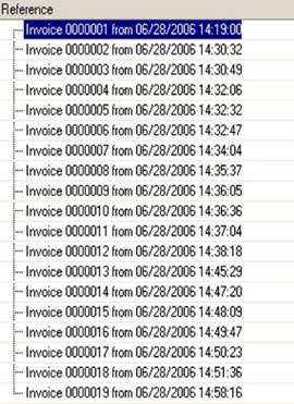
Fig. 350. Query result
8.4.7.2. Using the "DISTINCT" word
Most scenarios require that the same strings are not duplicated in the report.
Example:
// You need to find
counterparties to whom
// goods were shipped
for the period. Select
Document.SalesInvoice.CounterpartyResult:
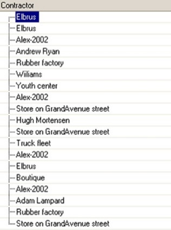
Fig. 351. Query result
As you can see, the query result contains a lot of duplicate strings, which reduces its visibility. To avoid duplicates, in the query description, specify the DISTINCT keyword.
Example:
Select Distinct
Document.SalesInvoice.CounterpartyResult:
Fig. 352. Query result
8.4.7.3. Using the "TOP" word
In some cases, you need to output a limited number of strings to a report. To do it, in the query description, specify the TOP keyword and enter the required number of strings after it.
Example:
// You need to select
the five most expensive products. // Selection must be
carried out in a descending order of the product price. Select Top 5
Catalog.Products.Description, Catalog.Products.PurchasePrice
ORDER BY
Catalog.Products.PurchasePrice
DescResult:
Fig. 353. Query result
8.4.7.4. Batch query
1C:Enterprise platform allows you to use query batches. Batch query is multiple queries linked using temporary tables. In a batch query, query texts are separated with a semicolon ;. Each query of the batch is handled separately. The batch queries are performed sequentially as they are described in the batch text. Each batch query is performed in DBMS as a separate query. Data composition system supports batch queries.
Example:
SELECT
ProductsAccountingBalanceAndTurnovers.Products, ProductsAccountingBalanceAndTurnovers.CountReceipt, ProductsAccountingBalanceAndTurnovers.CountExpense, ProductsAccountingBalanceAndTurnovers.CountClosingBalance
INTO ProductsAccounting
FROM
AccumulationRegister.ProductsAccounting.BalanceAndTurnovers(, , Auto, , ) AS ProductsAccountingBalanceAndTurnovers
;
SELECT
ProductsAccounting.Products, ProductsAccounting.CountExpense, ProductsAccounting.CountClosingBalance
FROM
ProductsAccounting
AS ProductsAccountingIn the given example, the batch query includes two queries: the first query gets some data from the BalanceAndTurnovers virtual table and places this data in a temporary table, and the second query gets data from this temporary table.
The query batch supports temporary tables. For more information about temporary tables, see Temporary table (query language) or Managing temporary tables (1C:Enterprise language).
For more information on using batch queries in 1C:Enterprise language, see Working with batch queries.
8.4.8. Selection field description
8.4.8.1. General information
After the required SELECT keyword and the refining DISTINCT and TOP words, specify a selection field list in a query text. These fields will be processed when selecting data in a query. The result of a query will also have a set of fields defined in this list. Selection fields are described according to the following rules:
<Selection field list>
<Selection field>[, <Selection field>[, ...]] | *<Selection field>
<Field description> |
<Logical expression> [[HOW] <Field alias>]<Field description>
<Expression>[.<Field group>]|<Empty
table description><Empty table description>
EMPTYTABLE.(<Alias list>)<Alias list>
[<Field alias>][,<Alias
list>]A selection field list consists of one or several comma-separated items. Each selection field consists of a selection field description and an optional field alias.
Instead of listing fields in the selection list, you can specify an asterisk (*). This will mean that the query result must contain all fields from source tables, which are query data sources described in the source list.
Note. Note 1. When specifying an asterisk (*) in the selection field list, the result does not include virtual fields of source tables.
Note. Note 2. To receive very large datasets (more than 64 MB), you need to have sufficient hard drive space used to place temporary server and client files.
A field description determines how to generate field values. In the simplest case, a selection field is a reference to a source table field. A reference can be specified indicating a table containing this field or without specifying the table itself. For field dereferencing, seeFields dereferencing.
In general, a selection field can be a reference to a source table field, an expression (see Expressions in query language), or a logical expression (see Logical expressions in query language).
Query results can be grouped (see Grouping query results) using aggregate functions (see Aggregate functions in query language) specified as expressions in selection fields.
An alias can be assigned to each selection field (see Field aliases in the selection list). Later, you can use the field alias to access this field more conveniently.
A group of fields can be specified only when a selection field refers to a nested table (see Nested tables in the selection field list). In this case, you can specify which fields must be processed in the selection by the nested table. If a group of fields is not specified, all nested table fields will be processed in the selection.
8.4.8.2. Field aliases in the selection list
If an alias is assigned to a selection field, it can be used to access the field, in the ORDER BY and TOTALS clauses, and for operations with a query result. Such access may be more convenient and visible, and in some cases the only possible one.
The AS keyword can precede the field alias. This word can be skipped. However, if it is specified, it increases the query text visibility and readability.
Field aliases are defined according to the rules for assigning variable IDs. Aliases in a query cannot be the same.
Assigning aliases to fields does not affect the data selection in a query.
Example:
// You need to select
names of goods and groups
// from the goods
catalog. Select
Catalog.Products.Description
As Product, Catalog.Products.Parent.Description
As Group
From
Catalog.ProductsResult:
Fig. 354. Query result (fragment)
Note that the fields in the query result are named Product and Group. If the field aliases were not specified, the fields in the query result would be named Description and Description1, which is less obvious. Field names in a query result cannot be the same. So, "1" is automatically added to the name of the second field.
8.4.8.3. Nested tables in the selection field list
A selection field list can refer to a nested table of a query data source. In this case, a query result field will be of the QueryResult type. It will contain a nested query result generated based on the nested table, which is a source.
By default, a nested result includes all fields of a nested table, which is a data source. You can explicitly define a group of fields that must be contained in a nested query result. A field group of a nested result is described according to the following rule:
<Field group>
( <Nested field list> ) | *<Nested field list>
<Nested field>[, <Nested
field>[, …]]<Nested field>
<Expression> [[AS] <Field
alias>]A list of nested fields consists of one or several comma-separated items. If the list consists of one item, it is not necessary to enclose it in brackets.
Instead of listing nested fields, you can specify an asterisk (*). This will mean that a query result must contain all the fields that are in the nested table.
A nested field can represent an expression (see Expressions in query language). In the simplest case, an expression is a reference to a nested table field.
Each nested field can be assigned an alias. Later, you can use a field alias to access it more conveniently, similar to selection list field aliases (see Field aliases in the selection list).
Aliases can be assigned to nested fields regardless of whether an alias is set to the nested table.
Example:
// A report must
display the specification of invoices
// the document itself,
products, and their quantity. Select
Document.SalesInvoice.Ref, Document.SalesInvoice.Content
(Products As Product, Count)Result:
Fig. 355. Query result (fragment)
Note that the Content field of the query result is a nested table that has the Products and Count fields.
8.4.8.4. Empty nested tables in the selection list
If a query uses merging and some merging parts contain nested tables and some do not, you need to supplement the selection list with fields, that is, empty nested tables. To do it, use the EMPTYTABLE keyword. After it, in brackets, specify field aliases that the nested table will contain.
Example:
SELECT
Ref.Number, EMPTYTABLE.(Num, Product, Count) AS Content
FROM
Document.SalesInvoice
UNION ALL
SELECT
Ref.Number, Content.(LineNumber, Products, Count)
FROM
Document.SalesInvoice8.4.9. Query source description
8.4.9.1. General information
Use the FROM clause to define a list of source tables, that is, data sources used in the SELECT operator.
Note that the FROM clause is optional in the query language. You can skip it if data sources are clearly identified in the selection field list description from the SELECT clause. Note that some examples in the previous sections did not contain the FROM clause.
After the FROM keyword, specify a list of sources. In general, the list of sources is described by the following set of rules:
<Source list>
<Source>[, <Source>[, …]]<Source>
[ <List of joins> ]<Source description>
<Table> [[AS] ]<Table>
<Table
name>[(<Parameters>)] | (<Query description>)Query data sources are listed in the source list and are separated by commas. Each source in the list of sources must include a source description and a list of joins, which are the rules for connecting sources with other sources. For the description of join features, see Join features.
If the infobase table serves as a data source, the source description contains a name of the table.
If the source table is virtual, its generation parameters can be specified. For the detailed description of virtual table parameters, see 1C:Enterprise language – Working with queries – Query tables in the built-in help.
A nested query can be a query data source. In this case, the source description contains a query description. For the description of using nested queries, see Nested queries in the source list.
In a data source description, its alias can also be assigned (seeData source aliases). Later, you can use the source alias to access it more conveniently.
8.4.9.2. Join features
8.4.9.2.1. General information
When defining several sources, for each record in the list from the first source table, selection is made from the second source table, and so on. So, all possible combinations of all records from all specified sources are generated in the query result.
Example:
SELECT
Counterparties.Ref AS
Counterparty, PriceTypes.Ref AS
PriceType
FROM
Catalog.Counterparties
AS Counterparties, Catalog.PriceTypes AS
PriceTypesResult:
Fig. 356. Query result (fragment)
The result of query contains combinations of all counterparties with all types of prices. As a rule, such result alone does not make sense. Usually, combinations of records from different source tables must be limited by some conditions. In the query language, you can describe such source join. To do it, specify the sources and determine conditions for including combinations of records from these sources in the query result.
Joins can be of several types. They are described by the following rules:
<List of joins>
<Join> [<List of
joins>]<Join>
[INNER] JOIN BY <Filter condition> |
LEFT [OUTER] JOIN BY <Filter condition> |
RIGHT [OUTER] JOIN BY <Filter condition> |
FULL [OUTER] JOIN BY <Filter condition> |In general, the list of joins can contain and describe not only a single join (of two sources) but also multiple joins of several sources at once.
Source description contains a source table description (see Query source description).
A filter condition contains conditions that describe how to join data from source tables, that is, query sources, in the selection. Do not use subqueries to describe filter conditions. This can significantly slow down a query and in some cases result in its failure in some DBMSs. For rules describing query language conditions, see Conditions in query language.
The LEFT, RIGHT, and FULL keywords specify join details. The INNER or OUTER words can be omitted. They increase the query text visibility and readability.
Sources to join are not equivalent to each other. In some cases, the result depends on which table is listed as the first one, that is, before the JOIN keyword (to the left), and which table is specified as the second one (to the right).
To describe joins, let us use two standard tables. The first table is called Companies and consists of two fields: Name and Phone. It contains the following data:

Fig. 357. "Companies" table
The other table is called Contacts and consists of three fields: Name, Phone, and Company (reference to the Companies table item). The table contains the following data:

Fig. 358. "Contacts" table
Note. Note. In 1C:Enterprise terms, both of the tables are catalogs.
8.4.9.2.2. Inner join
The inner join means that a query result must include only combinations of records that meet the specified condition from both source tables, which are data sources. The rest of records do not make to the result.
Example:
SELECT
Companies.Description AS Company, Contacts.Description AS Contact
FROM
Catalog.Contacts AS Contacts
INNER JOIN Catalog.Companies AS Companies
BY Contacts.Company = Companies.RefResult:

Fig. 359. Query result
8.4.9.2.3. Left outer join
The left outer join means that a query result must include combinations of records from both source tables meeting the specified condition. However, in contrast to the inner join, a query result must also include records from the first source (specified to the left of the JOIN word), for which no matching records from the second source were found.
So, a query result will include all records from the first source. They will be connected to records from the second source when the specified condition is met. Query result strings for which no matching records from the second source are found will contain NULL in the fields generated based on the records from this source.
Example:
SELECT
Contacts.Description AS Contact, Companies.Description AS Company
FROM
Catalog.Contacts AS Contacts
LEFT JOIN Catalog.Companies AS Companies
BY Contacts.Company = Companies.RefResult:

Fig. 360. Query result
8.4.9.2.4. Right outer join
The right outer join means that the result of query must include combinations of records from both source tables that meet the specified condition. In addition, the result of query should also include records from the second (indicated to the right of the JOIN word) source for which no matching records from the first source were found.
So, the result of query will include all records from the second source. They will be connected to records from the first source when the specified condition is met. Query result strings for which no matching records from the first source are found will contain NULL in the fields generated based on the records from this source.
Note. Note. In fact, the right outer join can be expressed through the left outer join. This is exactly what Designer Query Wizard does.
Example:
SELECT
Contacts.Description AS Contact, Companies.Description AS Company
FROM
Catalog.Contacts AS Contacts
RIGHT JOIN Catalog.Companies AS Companies
BY Contacts.Phone = Companies.PhoneResult:

Fig. 361. Query result
8.4.9.2.5. Full outer join
The full outer join means that the result of query must include combinations of records from both source tables that meet the specified condition. In addition, the query result must also include those records from both sources for which no matches were found.
So, the result of query will include all records from both sources. They will be connected to each other when the specified condition is met. Query result strings for which no matching records from any source are found will contain NULL in the fields generated based on the records from this source.
Example:
SELECT
Contacts.Description AS Contact, Companies.Description AS Company
FROM
Catalog.Companies AS Companies
FULL JOIN Catalog.Contacts AS Contacts
BY (Contacts.Phone = Companies.Phone)Result:

Fig. 362. Query result
8.4.9.3. Data source aliases
If the data source is assigned an alias, then in future it will be possible to access this source using this alias (and it will no longer be possible to access it by specifying the name of the table). Such access may be more convenient and visible, and in some cases the only possible one.
The alias is set in accordance with the rules for assigning variable IDs. Aliases in a query cannot be the same.
The AS keyword can precede a source alias. This word can be skipped. However, if it is specified, it increases the query text visibility and readability.
Assigning aliases to sources does not affect the data selection in a query.
Example:
SELECT
Product.Description, Product.Parent
FROM
Catalog.Products
AS ProductThis example demonstrates how to use the Product alias assigned to the Ref.Products source table in the selection field list.
8.4.9.4. Nested tables in the source list
The list of sources may include nested tables, that is, tables of catalogs and documents.
Example:
// A report must display the specification of
invoices
// the document itself, products, and their quantity.
// The source list contains the nested
"Content" table
// an invoice table.
// Selection is limited to eight entries in order not
to overload the example. SELECT TOP 8
SalesInvoiceContent.Ref, SalesInvoiceContent.Products, SalesInvoiceContent.Count
FROM
Document.SalesInvoice.Content
AS SalesInvoiceContentResult:
Fig. 363. Query result
Note that when specifying a nested table in the list of sources, you can refer both to the fields of the nested table itself and to the fields of the top level table (the one that contains the nested table) using the Ref field. In this case, the Ref.FieldDescription document field is referred to.
8.4.9.5. Nested queries in the source list
In the query source list, a nested query can be used as a source table. In this case, a source description contains a nested query description. A description of a nested query is made the same way as of a standard one (see Query description).
Using a nested query as a data source is no different from using an infobase table. All fields described in the selection field list of a nested query can be fields of such query.
Example:
SELECT
NestedSelect.Ref, NestedSelect.Products, NestedSelect.Count
FROM
(SELECT TOP 8
SalesInvoiceContent.Ref AS Ref, SalesInvoiceContent.Products AS Products, SalesInvoiceContent.Count AS Count
FROM
Document.SalesInvoice.Content
AS SalesInvoiceContent) AS NestedSelectThe result will be exactly the same as in the previous example.
8.4.10. Temporary table
8.4.10.1. General information
Temporary table is a table that is created and used in a specific session or the Query to the database. A temporary table stores temporary data that is used for a short time and does not require permanent storage. Temporary tables can be used, for example, to improve query performance: some data (which may take a significant time to obtain) is placed in a temporary table and then used repeatedly. Managing temporary tables is ensured by two components:
-
Query language syntax that allows creating new temporary tables and using the current ones.
-
The TempTablesManager object of 1C:Enterprise language that stores temporary table data.
This section contains description of the query language syntax and 1C:Enterprise language features (see Managing temporary tables).
A temporary table exists until one of the following occurs:
-
It is not explicitly deleted by a query language statement.
-
The Query object does no longer exist (if no temporary table manager was set in this query). If a new query text is set into an existing Query object, this is equivalent to destroying the Query object and creating a new object.
-
Destroying the temporary table manager that stores the temporary table.
8.4.10.2. Creating temporary tables
A temporary table can be created from database data or external data source (for example, a value table).
To create a temporary table based on database data, execute the database query using the INTO clause followed by the name of the temporary table to be created. The INTO keyword must be specified after the query selection list.
Example:
SELECT
Products.Code, Products.Description
INTO TemporaryTable
FROM
Catalog.Products AS ProductsThe values of the Code and Description attributes for all the Products catalog items will be placed in the temporary table. Temporary table names must meet the requirements for names of 1C:Enterprise language variables (see Names of variables, procedures, and functions).
Note that when you create a temporary table using the INTO clause, types of temporary table columns are implicitly specified, including the digit capacity for numeric columns and the length for string columns. If new values are added without taking into account the digit capacity, length, or type of temporary table column, a type mismatch error may occur. In such cases, when creating a temporary table, you can extend the column type using the CASE and CAST operators.
Use the RECORDAUTONUMBER() query language function to add a column to the created temporary table that will be filled with a unique number.
When creating temporary tables, you can use the FOR UPDATE construct. This is necessary in cases where it is required to retrieve data into a temporary table and simultaneously block it from reading by other transactions. This expression cannot be used if the temporary table is generated based on an external data source.
Example:
SELECT
SalesInvoice.Ref, SalesInvoice.Number, SalesInvoice.Date
INTO TemporaryTable
FROM
Document.SalesInvoice AS SalesInvoice
WHERE
SalesInvoice.Ref IN(&Documents)
FOR UPDATEIf a table of values is used as an external data source, then this table of values must explicitly indicate the types of values contained in the columns.
In order to create a temporary table based on an external source, the parameter name where the external source will be placed must be specified in the source list of the query text. Then create a temporary table as usual.
The following external data sources are available:
-
Value table
-
Table
-
Query result
An example of creating a temporary table based on the external data source is given below:
SELECT
Source.Code, Source.Description
INTO TemporaryTable
FROM
&ExternalSource AS SourceIn this example, the contents of the Code and Description columns from an external source will be placed in the TemporaryTable temporary table. For example, the external source can be a value table passed as the ExternalSource parameter. If the column value type is not specified in the value table that is used as the source for the temporary table, an error will be displayed. If a column without a specified type is used in any expression, for example in the CASE or ISNULL operations, an error will also be displayed.
Note. IMPORTANT. If a temporary table is created based on an external source, the query cannot use mergers and connections, as well as fields that are attributes of the table fields based on which the temporary table is created.
8.4.10.3. Adding data to temporary tables
To add data to an existing temporary table, use the ADD <TableName> clause. The data will be added if the structure of the existing temporary table and the query that adds new data to this table match. If the structure of the existing temporary table does not match the structure of the data to add, a runtime error will be generated. The order of records in a temporary table is not guaranteed and may depend on the DBMS on which the query is executed, on the query to retrieve data from the temporary table, and on whether there are indexes in the temporary table.
Note that the field in the query dataset list that precedes the ADD keyword must have an alias specified. Otherwise, the ADD word will be considered a field alias, and an error may occur when executing the query.
Example:
SELECT
Goods.Description AS Description
INTO ListOfDescriptions
FROM
Catalog.Goods AS Goods
;
SELECT
Services.Description AS Description
ADD ListOfDescriptions
FROM
Catalog.Services AS Services
;In the given example, the ListOfDescriptions temporary table is generated first. It contains a list of object names from the Goods catalog. The next query adds the names of objects located in the Services catalog to this temporary table.
8.4.10.4. Indexing temporary tables
Using indexes allows you to improve query performance in some cases. You can only use indexes to improve the performance of a temporary table. It is not allowed to use them to control uniqueness. Note that the behavior of different DBMS on which the platform operates may differ in terms of uniqueness control, and using unique indexes for this purpose will not ensure the correct solution of this issue. It is recommended that you use indexes for fields that will be used in result filtering conditions and in table join conditions.
To create an index for a temporary table, add the INDEX BY keyword to the query and specify the fields for building the index after this keyword.
Example:
SELECT
Products.Code AS Code, Products.Description
INTO TemporaryTable
FROM
Catalog.Products AS Products
INDEX BY
CodeFields used for indexing must be included in the selection list.
If one index for a temporary table is not enough, you can specify multiple indexes using the INDEX BY SETS clause:
INDEX BY SETS ((FieldsSet1) [ UNIQUE][ , (FieldsSet2) [ UNIQUE][,...]])
GroupingFieldsSetN
<Field dereferencing> [, <Field dereferencing> [, …]]
When you create several indexes, consider the following:
-
Fields in the index follow the order in which the fields are listed in the set description.
-
Indexes can be created only when a temporary table is being created, that is, in the query containing the INTO clause.
-
When creating multiple indexes, the first index will be clustered if Microsoft SQL Server is used. For other DBMS, the first index will be regular.
-
Any subsequent index (not the first one) will be a regular (non-clustered) index when using any DBMS.
Example:
SELECT
Products.Code AS Code, Products.Description AS Description, Products.SKU AS SKU
INTO ProductsData
FROM
Catalog.Products AS Products
INDEX BY SETS ( (Code, Description), (SKU)
)In the given example, the ProductsData temporary table is created, which
-
contains the Code, Description and SKU fields from the Products catalog.
-
Two indexes are created for the temporary table:
-
The first index includes the Code and Description fields.
-
The second index only includes the SKU field.
-
If a unique index is required for a temporary table, use the UNIQUE keyword along with the INDEX and INDEX BY SETS clauses. A unique index ensures that the index key will not contain duplicate values, meaning that each row in the table will be unique. Only one index can be unique.
Example:
SELECT
Products.Code AS Code, Products.Description AS Description, Products.SKU AS SKU
INTO ProductsData
FROM
Catalog.Products AS Products
INDEX BY
Code, Description UNIQUEIn the given example, a unique index is created for the ProductsData temporary table based on the set of Code and Description fields.
Example:
SELECT
Products.Code AS Code, Products.Description AS Description, Products.SKU AS SKU
INTO ProductsData
FROM
Catalog.Products AS Products
INDEX BY SETS ( (Code, Description), (SKU) UNIQUE
)In the given example, two indexes are created for the ProductsData temporary table.
-
Regular index by the Code and Description fields.
-
Unique index by the SKU field.
8.4.10.5. Using temporary tables
Temporary tables are used in the query language as regular tables, whose structure is defined when a temporary table is created.
Example:
SELECT
Receipt.Product, Receipt.Ref.Date AS Date, Receipt.Ref.Vendor
INTO WarehouseReceipt
FROM
Document.ReceiptOfGoods.Content AS Receipt
WHERE
MONTH(Receipt.Ref.Date) = 9
;
SELECT
Goods.Description, Goods.Manufacturer, WarehouseReceipt.Date, WarehouseReceipt.Vendor
FROM
Catalog.Goods AS Goods
LEFT JOIN WarehouseReceipt AS WarehouseReceipt
BY Goods.Ref = WarehouseReceipt.Product
ORDER BY
Goods.Description HIERARCHYIn the given example, a WarehouseReceipt temporary table is generated first. It contains goods from the ReceiptOfGoods documents that were registered in the 9th month. This temporary table is then used in a query that generates a following list: product, its manufacturer, supplier, and date the product was delivered (in September).
8.4.10.6. Dropping temporary tables
To drop a temporary table, use the DROP keyword of the query language followed by the name of the table being dropped, for example:
DROP TemporaryTableIf the table being dropped does not exist, an error will be generated.
8.4.11. Filtering query results
The WHERE <Filter condition> clause allows specifying a condition to filter data from source tables, that is, query sources. A query will process only records for which this condition is true.
Example:
// You need to find out
which counterparties are individuals. SELECT
Counterparties.Description
FROM
Catalog.Counterparties AS Counterparties
WHERE
Counterparties.Kind = Value(Enumeration. CounterpartiesKinds.Individual)Result:
Fig. 364. Query result
Note. Note. A field from the WHERE clause might be not included in the selection list.
A filter condition can be defined as a simple logical expression or as a more complex logical expression, where simple logical expressions are interconnected with the And, Or, and Not logical operators. For the description of conditions in the query language, see Conditions in query language.
When selecting data from a table that has tabular sections, conditions on tabular section records affect records to be selected from the table and tabular section records.
In general, records that contain tabular sections are selected as follows:
-
Tabular sections are connected to each table in the source list by the left outer connection.
-
All joins defined in the source list are performed.
-
Records that meet the WHERE section condition are selected.
-
Records are grouped by table fields from the source list, including reference fields. Tabular section records are placed as values of the respective table record fields from the selection list.
8.4.12. Grouping query results
8.4.12.1. Simple grouping
The source data in the query can be grouped using aggregate functions specified as fields in the selection list. This means that strings in the query result will contain results of evaluating the specified aggregate functions calculated (grouped) by records of source tables.
The aggregate functions themselves are specified in the list of selection fields. In the GROUP BY <Grouping fields> clause, specify a list of fields to group by. The query will group the source table records containing the same values of the specified fields.
The list of grouping fields contains references to the fields of the source tables, which are query sources separated with commas:
<Grouping fields>
<Field dereferencing> [, <Field dereferencing> [, …]]
Note. IMPORTANT. When grouping the results of a query, aggregate functions must be specified in the list of selection fields, and in addition to those, only the fields which the grouping is performed by are allowed to be specified. In queries containing grouping by any field, this field must not be used inside the aggregate functions. Using the field for grouping and within the aggregate function at the same time must be considered an error. Such queries can be interpreted differently, depending on which DBMS is used. If this rule is not complied with, errors may occur that cause program termination.
The exception is when the aggregate functions are applied to the fields of the nested table. In this case, is it possible to refer to the fields of the top-level table in the list of selection fields without grouping the results by these fields.
When using aggregate functions, the GROUP BY clause can be skipped. All query results will be grouped into one single string.
Example:
// You need to get
statistics on the sale of goods:
// the maximum,
minimum, and average prices in sales invoices. Select
Invoice.Products, Avg (Invoice.Price) As Avg
Max(Invoice.Price) As Max, Min(Invoice.Price) As Min
From
Document.SalesInvoice.Content As Invoice
GROUP BY
Invoice.ProductsResult:
Fig. 365. Query result (fragment)
8.4.12.2. Grouping data sets
Simple grouping (GROUP BY) allows evaluating defined aggregate functions per each data set which contains a unique combination of values for fields listed in the GROUP BY clause. However, a need may arise to get several aggregated results from a single data set with different grouping field sets.
For example, let us take the ProductsAccounting accumulation register. This register has the Products and Warehouse dimensions and the Count resource. You need to get quantitative stock for the following groupings:
-
By warehouse.
-
By product.
-
By product and warehouse.
To address the first task, you can use the following query:
SELECT
ProductsAccountingBalance.Warehouse AS Warehouse, SUM(ProductsAccountingBalance.CountBalance) AS CountBalance
FROM
AccumulationRegister.ProductsAccounting.Balance AS
ProductsAccountingBalance
GROUP BY
ProductsAccountingBalance.WarehouseTo address the second task, you can use the following query:
SELECT
ProductsAccountingBalance.Products AS Products, SUM(ProductsAccountingBalance.CountBalance) AS CountBalance
FROM
AccumulationRegister.ProductsAccounting.Balance AS
ProductsAccountingBalance
GROUP BY
ProductsAccountingBalance.ProductsThe last task can be addressed as follows:
SELECT
ProductsAccountingBalance.Products AS Products, ProductsAccountingBalance.Warehouse AS Warehouse, SUM(ProductsAccountingBalance.CountBalance) AS CountBalance
FROM
AccumulationRegister.ProductsAccounting.Balance AS
ProductsAccountingBalance
GROUP BY
ProductsAccountingBalance.Products, ProductsAccountingBalance.WarehouseAll the three tasks can be addressed either by executing the three queries in a row and processing the three results in 1C:Enterprise language or by executing the following merged query:
SELECT
NULL AS Products, ProductsAccountingBalance.Warehouse AS Warehouse, SUM(ProductsAccountingBalance.CountBalance) AS CountBalance
FROM
AccumulationRegister.ProductsAccounting.Balance AS
ProductsAccountingBalance
GROUP BY
ProductsAccountingBalance.Warehouse
UNION
SELECT
ProductsAccountingBalance.Products, NULL, SUM(ProductsAccountingBalance.CountBalance)
FROM
AccumulationRegister.ProductsAccounting.Balance AS
ProductsAccountingBalance
GROUP BY
ProductsAccountingBalance.Products
UNION
SELECT
ProductsAccountingBalance.Products, ProductsAccountingBalance.Warehouse, SUM(ProductsAccountingBalance.CountBalance)
FROM
AccumulationRegister.ProductsAccounting.Balance AS
ProductsAccountingBalance
GROUP BY
ProductsAccountingBalance.Products, ProductsAccountingBalance.WarehouseBoth of the described methods are applicable. However, they have a significant drawback: each of them executes a very similar query three times in a row. So far as significant data volumes are concerned, it may be time-consuming.
To reduce time required to handle the task, use the GROUPING SETS extension in the GROUP BY clause. GROUP BY GROUPING SETS allows evaluating all groupings in a single search by query tables.
The clause uses the following syntax:
Syntax:
GROUP BY GROUPING SETS ((GroupingFieldsSet1)[, (GroupingFieldsSet2)[,...]])GroupingFieldsSetN
<Field dereferencing> [, <Field dereferencing> [, …]]Technically, each GroupingFieldsSet is a grouping set. Aggregate functions available in a query will be similar for all grouping sets. If a query field is not involved in aggregation (it is not an aggregate function parameter), make sure that it is included at least in one grouping set. Grouping sets are supported for top-level tables only (including virtual tables).
So, the mentioned merged query can be written as follows:
SELECT
ProductsAccountingBalance.Products AS Products, ProductsAccountingBalance.Warehouse AS Warehouse, SUM(ProductsAccountingBalance.CountBalance) AS CountBalance
FROM
AccumulationRegister.ProductsAccounting.Balance AS
ProductsAccountingBalance
GROUP BY GROUPING SETS
( (ProductsAccountingBalance.Warehouse), (ProductsAccountingBalance.Products), (ProductsAccountingBalance.Products, ProductsAccountingBalance.Warehouse)
)The query result will include the results of all three queries (or one merged query). So, here we do not speak about another way for getting results. We speak about increasing the speed of getting the result and improving the performance.
If a query with grouping sets is executed, you can obtain the following result (a query result fragment is shown only):
Fig. 366. Query result (fragment)
Pay special attention to where you place round brackets in the grouping set description. So, the following expression (let it be E1):
GROUP BY GROUPING SETS
( (ProductsAccountingBalance.Products, ProductsAccountingBalance.Warehouse)
)is not similar to the following expression (let it be E2):
GROUP BY GROUPING SETS
( ProductsAccountingBalance.Products, ProductsAccountingBalance.Warehouse
)E1 is equivalent to the following expression:
GROUP BY
ProductsAccountingBalance.Products, ProductsAccountingBalance.WarehouseE2 is equivalent to the following expression:
GROUP BY GROUPING SETS
( (ProductsAccountingBalance.Products), (ProductsAccountingBalance.Warehouse)
)In other words, E2 describes two grouping sets, and each of them contains grouping by a single field:ProductsAccountingBalance.Products and ProductsAccountingBalance.Warehouse.
8.4.13. Conditions for aggregate function values
The HAVING <Filter condition> clause allows setting conditions for aggregate function values. In other query language structures, for example, in the WHERE clause, you cannot specify aggregate functions as conditions.
Example:
// You need to select
products that were sold in more than 20 pieces. SELECT
Invoice.Products, SUM(Invoice.Count) AS Count
FROM
Document.SalesInvoice.Content AS Invoice
GROUP BY
Invoice.Products
HAVING
SUM(Invoice.Count) > 20Result:
Fig. 367. Query result
Note. IMPORTANT. Only aggregate functions and fields, which are grouped by, can be used in filter condition.
8.4.14. Merging queries
It is possible to merge several queries in the query language. In this case, the records obtained using each of the merged queries will be combined into one result of the query.
When merging, each query collects data independently, and such operations as ordering the results and calculating totals are performed on the query merging result already.
The fields of the query result will be named as described in the list of fields for selecting the first of the merged queries. The fields of the remaining queries selection are matched with the result fields in accordance with the order in which they appear in the list of selection fields. The merged queries must have the same number of fields in the list of selection fields.
If the selection fields of the merged queries have different types, the query result fields will have a union type.
Query merging is described by the following rule:
<Merge queries>
UNION [ALL]
<Query
description>
[<Merge queries>]Query merging begins with the required UNION keyword followed by a description of the query to join. Then one more query can be added, and so on.
By default, when merging queries, completely identical strings in the query result, generated by different queries, are replaced with one string. If you need to leave different strings, the ALL keyword must be specified.
Example:
SELECT
Receipt.Products AS Product, SUM(Receipt.Count) AS Receipt, SUM(0) AS Expense
FROM
Document.ReceiptOfGoods.Content AS Receipt
GROUP BY
Receipt.Products
UNION
SELECT
Expense.Products, SUM(0), SUM(Expense.Count)
FROM
Document.SalesInvoice.Content AS Expense
GROUP BY
Expense.ProductsResult:
Fig. 368. Query result (fragment)
8.4.15. Ordering of query results
8.4.15.1. General information
The ORDER BY clause allows sorting strings in query results.
<Order results>
ORDER BY <Ordering
conditions><Ordering conditions>
<Ordering field>
[<Order>]
[, <Ordering
field> [<Order>][, …]]<Ordering field>
<Expression> <Order> ASC | DESC | HIERARCHY | HIERARCHY
DESCA comma-separated list of conditions according to which it is necessary to sort the result of the query is specified in the ORDER BY clause. The selections are ordered first by the first condition, then by the second one, and so on.
In general case, the ordering condition may be some kind of expression (see Expressions in query language). Query result strings will be ordered by values of this expression calculated for each string.
Ordering can be carried out in ascending or descending order of values. For tables for which the hierarchy property is set, ordering is carried out based on the hierarchy as well (see Ordering by hierarchy). The order can be set for each field independently. For the description of value comparison rules, see Value comparison rules.
The field that appears in the ordering conditions does not have to be included in the query result.
Example:
// You need to select
the five most expensive products
// and arrange them in
a descending order of price. SELECT TOP 5
Products.Description, Products.PurchasePrice
FROM
Catalog.Products AS Products
ORDER BY
Products.PurchasePrice DESCResult:
Fig. 369. Query result
8.4.15.2. Ordering by hierarchy
For catalogs, you can assign ordering by a catalog hierarchy.
Example:
SELECT
Catalog.Products.Description, Catalog.Products.FullDescr
ORDER BY
Catalog.Products.Description HierarchyResult:
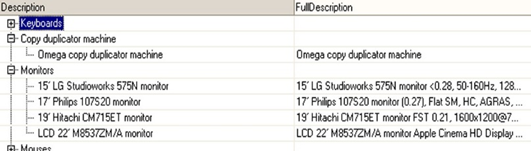
Fig. 370. Query result (fragment)
Hierarchical sorting is only possible by field, but not by some operation performed on it. The ordering field must contain a reference to the field of the source table that is the query data source.
Note. IMPORTANT. It makes sense to set the ordering by the hierarchy if it is the catalog table that is defined as the source, and not some other table containing only a reference to the catalog.
Example:
SELECT
SalesInvoice.Counterparty.Description, SalesInvoice.Number, SalesInvoice.Warehouse
FROM
Document.SalesInvoice AS SalesInvoiceIn this example, hierarchical ordering will not work, because there is no connection with the catalog, and the groups from this catalog will not be included in the query result.
To order by hierarchy it is necessary to arrange a connection with the catalog.
Example:
SELECT
Counterparties.Description AS Description, SalesInvoice.Number, SalesInvoice.Warehouse
FROM
Catalog.Counterparties AS Counterparties
LEFT JOIN
Document.SalesInvoice AS SalesInvoice
BY Counterparties.Ref = SalesInvoice.Counterparty
ORDER BY
Description HIERARCHYResult:
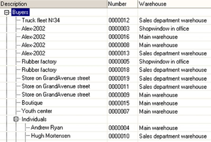
Fig. 371. Query result (fragment)
8.4.15.3. Ordering in nested tables
In the ORDER BY clause, you can also define conditions for ordering records from nested tables. You can combine them with conditions for ordering by the top-level table.
While doing this, the order in which you specify fields in the same level table (nested or top-level one) is important. However, the order of fields in tables of different levels in relation to each other does not matter. Ordering is always performed first by the top-level table, and then by the nested table.
Example:
// A report must
display the specification of invoices
// the document itself,
products, and their quantity. // Documents must be
ordered by number
// and the content must
be ordered by product name. Select
Document.SalesInvoice.Ref, Document.SalesInvoice.Content (Products As Product, Count)
ORDER BY
Document.SalesInvoice.Number, Document.SalesInvoice.Content.Products.Description8.4.15.4. Auto-ordering results
The AUTOORDER clause allows enabling the automatic generation of fields to order the query result.
Autoordering works based on the following principles:
-
If a query contains the ORDER BY clause, each reference to the table in this clause will be replaced with fields by which the table is sorted by default. For catalogs, this is a code or a name. For documents, this is a document date. If the field for ordering refers to a hierarchical catalog, then hierarchical sorting by this catalog will be applied.
-
If the query does not contain the ORDER BY clause but there is the TOTALS clause, the query result will be ordered by the fields from the TOTALS clause after the BY keyword in the same sequence. Besides, if the totals are calculated by reference fields, the query result will be also ordered by default sorting fields of tables which were referenced.
-
If the query does not contain the ORDER BY and TOTALS clauses but there is the GROUP BY clause, the query result will be ordered by the fields from the clause in the same sequence. Besides, if the grouping is carried out by reference fields, the query result will be also ordered by default sorting fields of tables which were referenced.
-
If the query does not contain the ORDER BY, TOTALS, and GROUP BY clauses, the result will be sorted by default sorting fields for the tables from which the data is selected in the order in which they appear in the query.
8.4.16. Calculating query totals
8.4.16.1. General information
The TOTALS clause allows defining which totals must be calculated in the query. When calculating totals, aggregate function values are calculated by datasets with the same values of checkpoint fields. Totals are added to the query result as totals rows.
The procedure for query totals calculating is described in accordance with the following rules:
<Totals description>
<Totals> [<Totals
description>]<Totals>
TOTALS [<Totals field list>]
BY [OVERALL] <Checkpoint list><Totals field list>
<Totals field> [,<Totals
field list> [, …]]<Totals field>
<Aggregate function> |
<Expression> [[AS] <Field alias>]<Checkpoint list>
<Checkpoint> [, <Checkpoint> [, …]]<Checkpoint>
<Expression>
[[ONLY] HIERARCHY] | [PERIODS(Second | Minute | Hour | Day | Week | Month |
Quarter | Year | TenDays | HalfYear
[,<DATE type
literal> | <Parameter ID>]
[,<DATE type
literal> | <Parameter ID>])] [[AS] Field alias]Description of the totals begins with the required TOTALS keyword.
The list of aggregate functions contains a list of aggregate functions (see Aggregate functions in query language) that must be calculated in the totals.
The OVERALL keyword means that it is required to generate a totals row for the entire query result. For the description of calculating grand totals, see Calculating grand totals.
Besides grand totals, you can set the totals calculation by checkpoints. To do this, after the required BY keyword, specify <Checkpoint list>. Each checkpoint contains an expression that is calculated when executing the query. For each combination of values of these expressions, the totals rows will be calculated and added to the query result.
If a checkpoint is a reference to a catalog, you can calculate totals by a catalog hierarchy (see Totals by hierarchy). To do this, after such reference, specify the required HIERARCHY keyword.
8.4.16.2. Calculating totals in nested tables
The current application version does not support the totals calculation by nested tables.
8.4.16.3. Totals by hierarchy
You can calculate totals by hierarchy. To do this, after the name of the field for which the totals are calculated, specify the HIERARCHY keyword. As a result, the system will calculate totals by checkpoints and totals by hierarchy for the checkpoints.
Example:
SELECT
Document.Products AS Products, Document.Count AS Count, Document.Ref.Number, Document.Ref.Counterparty
FROM
Document.SalesInvoice.Content AS Document
ORDER BY
Document.Products
TOTALS
SUM(Count)
BY
Products HIERARCHYResult:
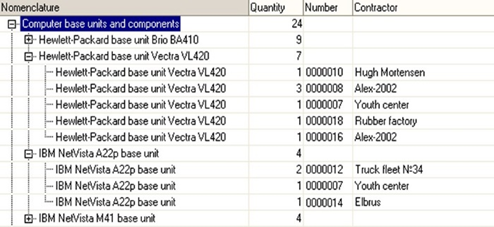
Fig. 372. Query result (fragment)
If necessary, you can calculate only value totals by hierarchy without calculating totals in checkpoints. To do this, specify the ONLY keyword before the HIERARCHY keyword.
Example:
SELECT
Document.Products
AS Products, Document.Count
AS Count, Document.Ref.Number, Document.Ref.Counterparty
FROM
Document.SalesInvoice.Content
AS Document
ORDER BY
Document.Products
TOTALS
SUM(Count)
BY
Products ONLY
HIERARCHYResult:
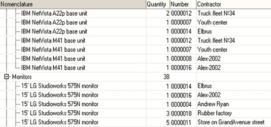
Fig. 373. Query result (fragment)
8.4.16.4. Adding dates
If the field for which the totals are calculated is a Date type field, it is possible to supplement the totals with dates in a given period. To do it, use the PERIODS keyword. After it, in brackets, specify a period type: Second, Minute, Hour, Day, Week, Month, Quarter, Year, TenDays, or HalfYear. Then specify start and end dates of the period. If the start and end dates are not specified, the first and last dates involved in the result will be used.
Example:
// Get the number of purchases by customers for
specific hours of the selected day
SELECT
ReceiptOfGoods.Counterparty, BEGINOFPERIOD(ReceiptOfGoods.Date, HOUR) AS Period, COUNT(ReceiptOfGoods.Ref)
AS PurchasesCount
FROM
Document.ReceiptOfGoods
AS ReceiptOfGoods
GROUP BY
ReceiptOfGoods.Counterparty, BEGINOFPERIOD(ReceiptOfGoods.Date, HOUR)
TOTALS
SUM(PurchasesCount)
BY
Period
PERIODS(MINUTE, DATETIME(2006,6,28), DATETIME(2006,6,28))Result:
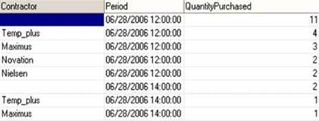
Fig. 374. Query result
This result presentation will be obtained only if all period records are used as a dimension source when bypassing the result by the Period grouping.
8.4.16.5. Calculating grand totals
To calculate totals for the entire table, specify the OVERALL word in the TOTALS clause. In this case, the values of the aggregate functions will be calculated for all the records in the table.
Example:
SELECT
Document.Products, Document.Count AS Count, Document.Ref.Number, Document.Ref.Counterparty
FROM
Document.SalesInvoice.Content AS Document
TOTALS
SUM(Count)
BY
OVERALLResult:
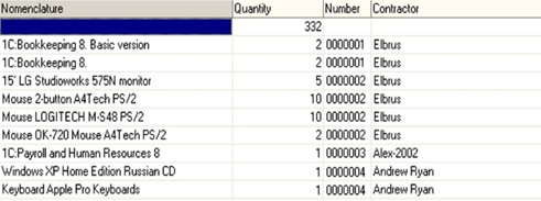
Fig. 375. Query result (fragment)
8.4.16.6. Using totals and grouping at once
If totals are used along with grouping and no list of aggregate functions is specified for the totals, it will be automatically generated from the aggregate fields of the selection list. If the query contains a union, aggregate functions will be taken from the first query.
Example:
SELECT
Document.Products AS Products, Document.Ref.Counterparty AS Counterparty, SUM(Document.Count) AS Count
FROM
Document.SalesInvoice.Content AS Document
GROUP BY
Document.Products, Document.Ref.Counterparty
TOTALS BY
Products, CounterpartyResult:
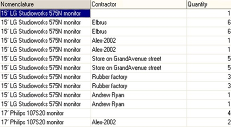
Fig. 376. Query result (fragment)
8.4.16.7. Totals aliases
You can assign an alias to totals fields, that is, checkpoints for which totals are calculated. Later, you can use the alias to access them from 1C:Enterprise language. To do this, after the expression, that is a checkpoint, specify an alias name the same way as in the selection field list.
Example:
SELECT
Document.Products AS Products, Document.Count AS Count, Document.Ref.Number, Document.Ref.Counterparty
FROM
Document.SalesInvoice.Content AS Document
ORDER BY
Document.Products
TOTALS
SUM(Count)
BY
Products ONLY HIERARCHY AS GoodsIf an alias is not specified, 1C:Enterprise application will provide a unique total name. In the example above, the total will be named Goods.
8.4.17. Expressions in query language
8.4.17.1. General information
Expressions can be used in many query language structures. Query language expressions are described by the following set of rules:
<Expression>
<Field
dereferencing> |
<Aggregate
function> |
<Built-in
function> |
<Selection
operation> |
<Type
casting>[.<Field dereferencing>] |
<Value> |
<Expression>
<Binary operation> <Expression> |
<Unary operation>
<Expression> |
( <Expression> )<Binary operation>
+ | - | * | /<Unary operation>
- | +In the simplest case, an expression is a reference to the source table field, which is a query data source. A reference can be specified indicating a table containing this field or without specifying the table itself. For the description of dereferencing fields, see Fields dereferencing.
Strings of unlimited length are not supported during the addition + operation. Strings longer than 1024 characters are treated as strings of unlimited length.
Expressions in the selection field list in the HAVING, TOTALS, and ORDER BY clauses can be aggregate functions (see Aggregate functions in query language).
An expression can be a built-in query language function. Selection operations (see Selection operations in query language) and value type cast operations can be used (see Type casting in query language).
The expressions can directly indicate the values of logical, numeric, string, and other constants. The values of the query parameters can also be used (see Constants and parameters in query language). Binary and unary operations can be applied to values of the corresponding types in the expressions. When using the division operation, it is recommended to perform a check of the divisor for difference from zero.
The type of SUM(), AVG(), CAST(), *, +, - operations, applied to numeric types will be a number with arbitrary precision and bitness.
In the arithmetic calculations, the platform tries to provide the accuracy not lower than 8 decimal places. If the DBMS provides higher accuracy (in any situation), the platform does not force rounding to 8 decimal places. It means that the use of a request to another DBMS (including the file variant) may result in another accuracy of an arithmetic calculation. If an arithmetic operation applied to the constant expressions is used in the request language expression, it may be calculated without sending to the DBMS and its accuracy may be different as compared to the calculation result obtained at the DBMS.
8.4.17.2. Fields dereferencing
In the simplest case, expressions of the query language are references to the fields of the tables of the infobase. In general, the references are described by the following rules:
<Field dereferencing>
[<Table>.]<Field
name>[.<Field name>[…]]<Table>
<Table name> |The dereferencing of a field begins with the name of the table containing this field. If a field name is unique, that is, it exists only in one table from those specified in the list of sources, the table can be omitted.
If the field has a reference type, the query language allows you to access the fields of the table referenced by the field, and so on. Field names are specified separated by a dot.
If the source table in the source list is assigned a source alias, it can be used instead of the table name in the field dereferencing of this table. Otherwise, the table name is specified (see Query source description).
8.4.17.3. Aggregate functions in query language
The query language provides aggregate functions that are used when grouping query results and when calculating totals. Aggregate functions are intended to summarize the values of the specified parameter. The following aggregate functions are defined:
<Aggregate function>
SUM ( <Expression> ) |
AVG ( <Expression> ) |
MIN ( <Expression> ) |
MAX ( <Expression> ) |
COUNT ( [DISTINCT]
<Expression> | * )Example:
SELECT
Invoice.Products.Description, SUM(Invoice.Sum) AS Sum, AVG(Invoice.Sum) AS Avg, MAX(Invoice.Sum) AS Max, MIN(Invoice.Sum) AS Min, COUNT(Invoice.Sum) AS Count
FROM
Document.SalesInvoice.Content AS Invoice
GROUP BY
Invoice.Products, Invoice.Products.Description
TOTALS BY
OVERALLResult:
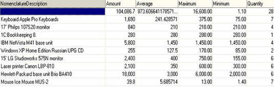
Fig. 377. Query result (fragment)
Aggregate functions can be used in the selection field list in the HAVING, TOTALS, and ORDER BY clauses. Aggregate functions should be used in the selection field list to obtain a result only. It is not recommended to use aggregate functions in the selection field list for comparison.
Correct query:
SELECT
COUNT(*), Vendor
FROM
Document.SalesInvoice
AS Invoice
GROUP BY
Vendor
HAVING
COUNT(*) > 1Incorrect query:
SELECT
WHEN COUNT(*) > 1 THEN True ELSE False END, Vendor
FROM
Document.SalesInvoice AS Invoice
GROUP BY
VendorAlthough an incorrect query can operate successfully, using an aggregate function not to obtain a result but to check the condition in theSELECT section might have different effects in different DBMS and can cause errors.
SUM
Description:
The function calculates the arithmetic sum of all the field values that were included in the selection.It is possible to specify only the fields that contain a numeric value as the function parameter.
If a field cannot contain numeric values, then using the SUM function to such field will cause an error. This function can be applied to such field only if the field can contain numeric values (has a union data type). But if there is a non-numeric value (in addition to NULL values) among the values of the field in the selection, this will cause an error.
AVG
Description:
The function calculates the average value of all the field values that were included in the selection.It is possible to specify only the references to the fields that contain a numeric value as the function parameter.
If a field cannot contain numeric values, then using the AVG function to such field will cause an error. This function can be applied to such field only if the field can contain numeric values (has a union data type). But if there is a non-numeric value (in addition to NULL values) among the values of the field in the selection, this will cause an error.
MIN
Description:
The function calculates the minimum value of all the field values that were included in the selection.It is possible to specify the references to the fields that contain any value types as the function parameter.
When determining the minimum value, the rules for comparing values are applied, as described in the "Value comparison rules" section.
MAX
Description:
The function calculates the maximum value of all the field values that were included in the selection.You can specify an expression containing values of any type as a function parameter. Cannot be applied to expressions with the ValueStorage, PointInTime type and strings of unlimited length.
When determining the maximum value, the rules for comparing values are applied, as described in the "Value comparison rules" section.
COUNT
Description:
The function counts the number of parameter values that included in the selection. The COUNT function has three usage scenarios in contrast to the other aggregate functions:-
The function allows you to count the number of values of the specified field that are not equal to NULL.
-
The function allows you to count the number of different values of the specified field that are not equal to NULL. To do this, before specifying the field, the DISTINCT keyword must be set.
-
The function allows to count the number of rows in the query result. To do this, it is necessary to specify an asterisk * as a function parameter.
It is possible to specify the references to the fields that contain any value types as the function parameter.
Example:
SELECT
COUNT(*) AS Total, Count(DISTINCT Invoice.Products) AS Distinct
FROM
Document.SalesInvoice.Content AS InvoiceResult:

Fig. 378. Query result
8.4.17.4. Built-in functions in query language
8.4.17.4.1. General information
Built-in functions are defined in the query language that can be used in expressions in the list of selection fields and in the selection condition in the WHERE clause (see Filtering query results).
8.4.17.4.2. RECORDAUTONUMBER
The function generates a field with a unique, consistently increasing value in the temporary table. The function may be used if it is necessary to create a key field in a temporary table. The value generated by the function will be unique within the temporary table, during the generation of which the function was used. The counter initial value depends on the used DBMS and, in the general case, can be any. It is not guaranteed that the counter initial value will be 1 for any temporary table.
The RECORDAUTONUMBER() function is not supported:
-
In queries containing UNION at the top level
-
In queries that do not generate a temporary table
-
Outside the selection list
-
In query language expressions
Example:
SELECT
PaymentsToVendor.Vendor AS Vendor, PaymentsToVendor.Currency AS Currency, SUM(PaymentsToVendor.Sum) AS Sum, RECORDAUTONUMBER() AS Key
INTO Payments
FROM
Document.PaymentsToVendor AS PaymentsToVendor
GROUP BY
PaymentsToVendor.Vendor, PaymentsToVendor.CurrencyResult:
As a result, the Payments temporary table will be created, where there will be a sequentially increasing numerical value as a value of the Key field.
8.4.17.4.3. Algebraic functions
You can use these functions to perform various algebraic functions:
| Function | Description |
|---|---|
| EXP | Calculates the value of the e constant raised to a given power. |
| LOG | Calculates the natural logarithm of the ln() number. |
| LOG10 | Calculates the natural logarithm of the lg() number. |
| POW | Raises a Base to a Factor power. |
| SQRT | Calculates the square root of a number. |
8.4.17.4.4. UPPER
Converts all characters of a parameter string to uppercase.
8.4.17.4.5. YEAR
This function calculates the year number from a Date type value.
A function parameter is a Date type expression.
If the parameter is a Date type value, the result of the function will be a Number type value. If the parameter is NULL, the result is also NULL. Other values are considered invalid and will cause an error.
8.4.17.4.6. DAY
This function returns a day of the month from a Date type value. The day of the month is in the range of 1–31.
A function parameter is a Date type expression.
If the parameter is a Date type value, the result of the function will be a Number type value. If the parameter is NULL, the result is also NULL. Other values are considered invalid and will cause an error.
8.4.17.4.7. DAYOFYEAR
This function returns a day of the year from a Date type value. The day of the year is in the range of 1–366.
A function parameter is a Date type expression.
If the parameter is a Date type value, the result of the function will be a Number type value. If the parameter is NULL, the result is also NULL. Other values are considered invalid and will cause an error.
8.4.17.4.8. WEEKDAY
This function returns a day of the week from a Date type value. The day of the week is in the range from 1 (Monday) to 7 (Sunday).
A function parameter is a Date type expression.
If the parameter is a Date type value, the result of the function will be a Number type value. If the parameter is NULL, the result is also NULL. Other values are considered invalid and will cause an error.
8.4.17.4.9. STRINGLENGTH
Returns the length of a parameter string as a number.
8.4.17.4.10. DATEADD
This function adds a value to a date.
The first parameter is the initial date, an expression of the Date type. The specified value determined by the second and third parameters is added to the initial date value.
The second parameter is the period by which the initial date will be increased: Second, Minute, Hour, Day, Week, Month, Quarter, Year, TenDays, or HalfYear. Note that TenDays means exactly 10 days, regardless of the date specified in the first function parameter.
The third parameter is a value by which the date specified by the first parameter must be increased. Type: Number (fractional part is ignored).
It is recommended to specify the third parameter (dimension of magnification) so that it corresponds to the applied task being solved. So, if an applied task operates with days or months, then days and months must be added to the date. Using large numbers as the values of the second and third parameters can cause the following problems:
-
Different implementation of daylight-saving transition in different DBMS.
-
Going beyond the range of dates supported by the DBMS.
-
Going beyond the permissible parameter values.
Example:
SELECT DATEADD(DATETIME(2002, 10, 12, 10, 15, 34), MONTH, 1)Result:
Fig. 379. Query result
Example:
SELECT DateAdd(DateTime(2002, 10, 12, 10, 15, 34), Day, 5)Result:

Fig. 380. Query result
8.4.17.4.11. ISNULL
The function replaces the NULL value with another value.
Function parameters:
-
The first parameter is an expression of any type.
-
The second parameter is an expression of any type.
Returns the value of the first parameter if the first parameter does not contain the NULL value. Otherwise, returns the value of the second parameter.
The second parameter will be converted to the type of the first one if the type of the first parameter is a string or a number.
Example:
// Get the sum of the
Quantity field. In case if it is not
// records, receive 0
SELECT
ISNULL(SUM(SalesInvoiceContent.Count), 0)
FROM
Document.SalesInvoice.Content AS SalesInvoiceContent8.4.17.4.12. QUARTER
This function returns a quarter number from a Date type value. The quarter number is in the range of 1–4.
A function parameter is a Date type expression.
If the parameter is a Date type value, the result of the function will be a Number type value. If the parameter is NULL, the result is also NULL. Other values are considered invalid and will cause an error.
8.4.17.4.13. ENDOFPERIOD
This function extracts a certain date from a given date.
Parameters of this function include an expression of the Date type and one of the values defining the period type: Minute, Hour, Day, Week, Month, Quarter, Year, TenDays, or HalfYear. If the period type is set to Week, the value of the First weekday property of the infobase regional settings is considered.
Example:
SELECT ENDOFPERIOD(DATETIME(2002, 10, 12, 10, 15, 34), MONTH)Result:

Fig. 381. Query result
Example:
SELECT ENDOFPERIOD(DATETIME(2002, 10, 12, 10, 15, 34), YEAR)Result:

Fig. 382. Query result
8.4.17.4.14. LEFT
This function returns leading characters of a parameter string.
Parameters:
- String. Source string.- CountOfCharacters. The number of characters from the beginning of the string to be returned by the function. Negative values are considered to be zero. If there are fewer characters in the source string than in the parameter, the source string is returned.
8.4.17.4.15. MONTH
This function calculates a month number from a Date type value. The month number is in the range of 1–12.
A function parameter is a Date type expression.
If the parameter is a Date type value, the result of the function will be a Number type value. If the parameter is NULL, the result is also NULL. Other values are considered invalid and will cause an error.
8.4.17.4.16. MINUTE
This function returns the minute of an hour from a Date type value. The minute of the hour is in the range of 0–59.
A function parameter is a Date type expression.
If the parameter is a Date type value, the result of the function will be a Number type value. If the parameter is NULL, the result is also NULL. Other values are considered invalid and will cause an error.
8.4.17.4.17. BEGINOFPERIOD
This function extracts a certain date from a given date.
Parameters of this function include an expression of the Date type and one of the values defining the period type: Minute, Hour, Day, Week, Month, Quarter, Year, TenDays, or HalfYear. If the period type is set to Week, the value of the First weekday property of the infobase regional settings is considered.
Example:
SELECT BEGINOFPERIOD(DATETIME
(2002, 10, 12, 10, 15, 34), MONTH)Result:

Fig. 383. Query result
Example:
SELECT
BEGINOFPERIOD(DATETIME(2002, 10, 12, 10, 15, 34), DAY)Result:

Fig. 384. Query result
8.4.17.4.18. WEEK
This function returns a week number from a Date type value.
A function parameter is a Date type expression.
If the parameter is a Date type value, the result of the function will be a Number type value. If the parameter is NULL, the result is also NULL. Other values are considered invalid and will cause an error. The calculation considers the value of the First weekday property of the infobase regional settings.
8.4.17.4.19. LOWER
Converts all characters of a parameter string to lowercase.
8.4.17.4.20. ROUND
Rounds a parameter number to the required number of decimal places. Rounding is carried out similarly to the Round() function of 1C:Enterprise language in case the RoundMode parameter is set to Round15as20.
Parameters:
- Number. A number to be rounded. The accuracy corresponds to the number of digits.- DigitCapacity. Defines the number of decimal places in the result. If the parameter is negative, the number is rounded to the corresponding digit in the integer part starting from the lower digits. The fractional part of the parameter value is ignored.
The parameter is optional.
Default value: 0.
8.4.17.4.21. SUBSTRING
This function extracts a substring from a string. Three parameters are passed to the function:
-
String to extract a substring from. String type expression.
-
Character position where the extracted substring begins. Number type value.
-
Substring length. Number type value.
If the first parameter is a string, the result is a string (it can have zero length). If the first parameter is NULL, the result is also NULL. Other values are considered invalid and will cause an error.
Example:
SELECT TOP 8
Counterparties.Description, SUBSTRING(Counterparties.Description, 3, 5) AS Substring
FROM
Catalog.Counterparties AS CounterpartiesResult:
Fig. 385. Query result
8.4.17.4.22. RIGHT
This function returns trailing characters of the parameter string.
Parameters:
- String. Source string.- CountOfCharacters. The number of characters from the end of the string to be returned by the function. Negative values are considered to be zero. If there are fewer characters in the source string than in the parameter, the source string is returned.
8.4.17.4.23. PRESENTATION
This function returns a string presentation of an arbitrary type value.
A function parameter is an expression of any type.
A return value is a value presentation. Type: String.
The function result cannot be used inside other functions, except for the PRESENTATION function.
Example:
SELECT
PRESENTATION(Document.Counterparty) AS Recipient, PRESENTATION(Document.Date) AS Date
FROM
Document.SalesInvoice AS DocumentResult:
Fig. 386. Query result
8.4.17.4.24. STOREDDATASIZE
Returns the size that the fields specified as a parameter occupy in the database. The size is returned in bytes. The actual data size may differ from the size this function returns. The function can return different values in different database management systems under the same conditions.
8.4.17.4.25. DATEDIFF
This function returns an interval between two dates.
The first parameter is an expression of the Date type. The second parameter is an expression of the Date type. The third parameter is the type of difference, one of the following values: Second, Minute, Hour, Day, Month, Quarter, or Year.
It is recommended to specify the third parameter (type of difference) so that it corresponds to the applied task being solved. Thus, if the applied task operates with days or months, then it is necessary to calculate the difference of dates in days or months. It is not recommended to retrieve inadequate (in terms of the applied task) difference of dates and then bring it to the desired difference by means of the query language or 1C:Enterprise language. This recommendation is due to the fact that the calculation of the difference with a very high discreteness (seconds, minutes, hours) can take different account of the daylight saving transitions on different DBMS.
The use of this function is not supported when setting the Period virtual table parameter value.
Example:
SELECT DATEDIFF(DATETIME(2002, 10, 12, 10, 15, 34), DATETIME(2002, 10, 14, 9, 18, 06), DAY)Result:

Fig. 387. Query result
Example:
SELECT DATEDIFF(DateTime(2002, 10, 12), DateTime(2002, 11, 03), MONTH)Result:

Fig. 388. Query result
Note. IMPORTANT. The function returns the calendar difference between two dates, so it cannot be used where it is necessary to calculate the number of banking or business days between two dates.
8.4.17.4.26. GROUPEDBY
Use this function to determine that grouping was performed in this line by the field specified as a function parameter.
Parameters:
A parameter is a field to check.The function returns True, if a function parameter available in this string is used for grouping purposes and otherwise it will be False.
Example:
SELECT
CASE
WHEN GROUPEDBY(ProductsAccountingBalance.Product) THEN ProductsAccountingBalance.Product
ELSE "<< All goods >>"
END AS Product, CASE
WHEN GROUPEDBY(ProductsAccountingBalance.Warehouse) THEN ProductsAccountingBalance.Warehouse
ELSE "<< All warehouses >>"
END AS Warehouse, SUM(ProductsAccountingBalance.CountBalance) AS CountBalance
FROM
AccumulationRegister.Inventory.Balance AS ProductsAccountingBalance
GROUP BY GROUPING SETS
( (ProductsAccountingBalance.Warehouse), (ProductsAccountingBalance.Product)
)Result:
As a result of this query, the << All goods >> or << All warehouses >> values (depending on the field to which this function is applied) will be placed in fields that were not used in each result string for grouping.
See also:
- Grouping sets (see Grouping data sets).
8.4.17.4.27. SECOND
This function returns the second of a minute from a Date type value. The second of a minute is in the range of 0–59.
A function parameter is a Date type expression.
If the parameter is a Date type value, the result of the function will be a Number type value. If the parameter is NULL, the result is also NULL. Other values are considered invalid and will cause an error.
8.4.17.4.28. TRIML
This function removes insignificant characters to the left of the first significant character in a string.
8.4.17.4.29. TRIMALL
This function removes insignificant characters from both sides of a string.
8.4.17.4.30. TRIMR
This function removes insignificant characters to the right of the last significant character in a string.
8.4.17.4.31. STRREPLACE
This function replaces all occurrences of the searched substring with another substring in the source string. The search is case-insensitive.
Parameters:
- String. The string where search is performed.-
SearchSubstring. The substring to search for.
-
ReplaceSubstring. The substring to replace with.
Return value:
The source string in which all possible replacements are made.
If the second parameter is a constant, the length of the resulting string is <String>+(<String>/<SearchSubstring> rounding up)(<ReplaceSubstring>-<SearchSubstring>), but not shorter than <String> length. If the second parameter is not a constant, the length of the resulting string is <String><ReplaceSubstring>. If the resulting length is greater than 1024, the string is of unlimited length.
8.4.17.4.32. STRFIND
Returns the position of the searched substring in the string. The search is case-insensitive.
Parameters:
- String. Source string.- SearchSubstring. The searched string.
Return value:
The position of the found substring, starting from 1. If 0 is returned, the search substring is not found.
8.4.17.4.33. STRING
The function converts a primitive type value to a string considering regional settings. An error occurs when attempting to execute a query when applied to a non-primitive type. When applied to NULL, returns NULL.
Conversion is supported for values of the following types: Number, Boolean, String, Date, NULL, and Undefined.
8.4.17.4.34. VALUETYPE
The function returns the type of value in the query.
Parameters:
A function parameter is an expression of any type.Return value:
Value of the Type type. If the function parameter is Undefined, the return value will also be Undefined.
Example:
SELECT
VALUETYPE(ProductsAccounting.Recorder) AS Document
FROM
AccumulationRegister.ProductsAccounting AS ProductsAccounting8.4.17.4.35. Trigonometric functions
Use them to perform trigonometric functions. The function parameter is specified in radians.
| Function | Description |
|---|---|
| ACOS(<X>) | Calculates the value of the arccos() function. |
| ASIN(<X>) | Calculates the value of the arcsin() function. |
| ATAN(<X>) | Calculates the value of the arctg() function. |
| COS(<X>) | Calculates the value of the cos() function. |
| SIN(<X>) | Calculates the value of the sin() function. |
| TAN(<X>) | Calculates the value of the tg() function. |
8.4.17.4.36. UUID
A passed link UUID.
Parameters:
The function parameter is an expression whose result is a reference value (except for references to tables of external data sources).Return value:
Depends on the function parameter value:
-
NULL – NULL.
-
Undefined. Empty UUID of the UUID type.
-
For the reference type value, returns the UUID type value.
-
For other types (including those in the union type), a runtime error occurs.
Example:
SELECT
Goods.Ref AS Ref, UUID(Goods.Ref) AS UUID
FROM
Catalog.Goods AS Goods8.4.17.4.37. INT
Returns the integer part of the parameter number completely removing the fractional part.
8.4.17.4.38. HOUR
This function returns the hour of the day from a Date type value. The hour of the day is in the range of 0–23.
A function parameter is a Date type expression.
If the parameter is a Date type value, the result of the function will be a Number type value. If the parameter is NULL, the result is also NULL. Other values are considered invalid and will cause an error.
8.4.17.5. Selection operations in query language
Query language expressions can use selection operations that allow one of the possible values to be retrieved in accordance with the specified conditions.
The selection operation is described by the following set of rules:
<Selection operation>
CASE
<Selection
alternatives>
[ELSE
<Expression>]
END<Selection alternatives>
<Single choice>
[<Selection
alternatives>]<Single choice>
WHEN <Logical
expression> THEN <Expression>An unlimited number of alternative single choices can be specified in a WHEN ... THEN select operation. These are processed sequentially in the query. If the logical expression is True, the selection operation processing is completed. The operation result is a value of the expression specified after THEN. This expression (<Expression> in the chart above) cannot simultaneously include a field with no size limit (a string of unlimited length and a value store) and a field of other types. For the rules of generating logical expressions, see Logical expressions in query language.
The value of the expression specified after ELSE is used as the choice operation result if the predicate was set to False in all previously specified alternative single choices. This expression also does not support simultaneous use of fields with no size limit and fields of other types.
Example:
SELECT
Products.Description, CASE
WHEN Products.IsFolder = True THEN "This is group"
WHEN Products.PurchasePrice > 1000 THEN "1000 "
WHEN Products.PurchasePrice > 100 THEN "100 - 1000"
WHEN Products.PurchasePrice > 10 THEN "10 - 100"
WHEN Products.PurchasePrice > 0 THEN "0 - 10"
ELSE "Not specified"
END AS Price
FROM
Catalog.Products AS ProductsResult:
Fig. 389. Query result (fragment)
8.4.17.6. Type casting in query language
Fields in source tables can have a union type. For such fields, it is necessary to bring the field values to a specific type. The query language provides the feature to cast the type. It can be used in the list of selection fields and in the selection condition in the WHERE clause.
<Type casting>
CAST ( <Expression> AS
<Value type> )<Value type>
Boolean |
Number [(Length[, Precision])]|
String [(Length)]|
Date |
<Table name><Length>
Number<Precision>
NumberThe expression is cast to one of the primitive types or to the reference data type. In the second case, a table name refers to the respective infobase table.
If an expression contains a required type of value within a union type, then the type casting is considered feasible, and for each value of the specified type, the result will be the same value. For values of other types, the result of the cast will be NULL.
If the expression does not contain the required type of value within the union type, then the execution of this query will fail with an error due to the impossibility to perform a type casting.
8.4.17.7. Constants and parameters in query language
Query language expressions can directly indicate values of the Boolean, Number, String, or Date type. Query parameter values may also be used.
<Value>
TRUE |
FALSE |
<NUMBER type
literal> |
<STRING type
literal> |
<DATE type
literal> |
<TYPE type
literal> |
<Parameter name>
|
UNDEFINED |
NULL<Number type literal>
<Integer>[.<Integer number>]<String type literal>
"<Character
sequence>"<Date type literal>
DATETIME ( <Integer>, <Integer>, <Integer>[, <Integer>, <Integer>, <Integer>] )Values of the Boolean, Number, String type in the query language are set in the same way as in 1C:Enterprise language.
Values of the Date type are specified using the DATETIME keyword, after which the year, month, day, hour, minute, second are successively indicated in round brackets. The last three values are optional.
Note. IMPORTANT. The maximum date that can be set using the DATETIME literal is 12/31/3999 23:59:59.
Parameters can be passed to the query (see the description of the Query object). Parameter values can be used in query language expressions. To do this, it is necessary to specify the "&" character followed by the parameter name.
<Type type literal>
TYPE(<Type name>)<Type name> is a primitive type name or a name of the table whose reference type must be received. The result of this structure is the value of the Type type for the specified type.
Example:
// Retrieving String type
TYPE(String)
// Retrieving type - a reference to the Products
catalog
TYPE(Catalog.Products)Type type values in the query language can be used in comparison, ordering, and grouping operations.
Example:
SELECT
VALUETYPE(Balance.Recorder)
FROM
AccumulationRegister.ProductsAccounting
AS Balance
WHERE
VALUETYPE(Balance.Recorder) = TYPE(Document.SalesInvoice)You can pass a Type type value as a query parameter.
Example:
SELECT
VALUETYPE(Balance.Recorder)
FROM
AccumulationRegister.ProductsAccounting
AS Balance
WHERE
VALUETYPE(Balance.Recorder)
= &TypeWhen comparing values of the Type type, the values are ordered as follows (the first type is considered the smallest):
-
NULL
-
Undefined
-
Boolean
-
Number
-
Date
-
String
-
Table reference
-
Other types
8.4.18. Conditions in query language
8.4.18.1. General information
In the query language, the selection conditions are used, in accordance with which the data are filtered in the WHERE, HAVING, and JOIN clauses. The conditions are described according to the following rules:
<Filter condition>
<Logical addend> [Or
<Logical addend>]<Logical addend>
<Logical multiplier> [And
<Logical multiplier>]<Logical multiplier>
Not <Logical
multiplier> |
( <FIlter
condition> ) |
<Logical
expression>In the simplest case, the condition is an expression the result of which is a logical type value. Logical expressions are described in the next section.
Conditions can also be defined as more complex logical expressions, where simple logical expressions appear, interconnected by means of the And, Or, Not logical operators.
Logical operators have the following priorities:
-
Not has the highest priority.
-
And is the next in priority.
-
Or has the lowest priority.
-
In the conditions, simple logical expressions are calculated first, then Not operations, then And operations, and, finally, Or operations. Round brackets () can be used to ensure a different calculation order.
8.4.18.2. Logical expressions in query language
expressions in query languageLogical expressions are used in the query language in selection operations and in filter conditions.
<Logical expression>
<Expression> |
( | ) <Comparison operation> (<Expression> |
<Logical expression>) |
<Expression>
[Not] IN [HIERARCHY] (<Value list>) |
<Expression>
[Not] IN [HIERARCHY](<Query description>) |
<Expression>
[Not] BETWEEN <Expression> AND <Expression> |
<Expression> IS
[Not] NULL |
<Expression> REFS
<Table name> |
<Expression>
[Not] LIKE <STRING type literal>
[ESCAPE <STRING type literal>]<Comparison operation>
> | < | = | >= | <= |
<><Value list>
<Expression>[, <Expression> [, …]]A logical expression can be:
-
A regular expression of the query language if its result has a logical type.
-
An operation of comparing two expressions of the query language. It is performed in accordance with the rules for comparing values described in the "Value comparison rules" section (see Value comparison rules).
-
An operator checking the match/mismatch of the expression value with one of the listed values or with the values contained in the result of another query.
-
An operator checking whether the expression is included in the range.
-
An operator checking an expression value for NULL.
-
An operator checking a reference value of the expression for a reference to a specific table.
-
An operator checking whether the string value matches the template.
When comparing values, the rules for comparing values described below are applied.
8.4.18.3. Value comparison rules
In this section, you can read about the rules for comparing values of different types in a query.
These rules are used to perform the following actions:
-
Compare values in comparison operators.
-
Determine the maximum and minimum values in the MIN and MAX aggregate functions.
-
Arrange query result records in accordance with the order specified in the ORDER BY clause.
If value types differ from each other, the relationship between the values is defined based on type priorities:
-
NULL (the lowest priority)
-
Undefined
-
Boolean
-
Number
-
Date
-
String
-
Reference types
The relationship between different reference types is defined based on their internal table reference numbers corresponding to one type or another.
If data types are identical, their values are compared according to the following rules:
-
For the Boolean type, True is greater than False.
-
For the Number type, common number comparison rules are applied.
-
For the Date type, earlier dates are less than later dates.
-
For the String type, the comparison is performed in accordance with the established national database characteristics and the specified sorting order. The comparison is case insensitive. The string comparison operation does not consider trailing spaces, unlike string comparison in 1C:Enterprise language where trailing spaces are included during the comparison operation. For example, comparing strings "bb" and "bb " in 1C:Enterprise language will return False (strings are not equal) and True in the query language (strings are equal). At the same time, it is not guaranteed that the sorting of the same data set performed on different DBMS will return the same result.
-
Reference types and values with the UUID type are compared based on their values. At the same time, the repeatability of the comparison result is guaranteed only within one database.
-
Comparing fields with theUUID type with fields of other types is not supported.
-
It is not allowed to compare fields of unlimited length (strings of unlimited length, ValueStorage, the ValueType field from the table of the chart of characteristic types).
If the operation of comparing two values is used, where at least one NULL value is involved, NULL will be the result of the operation. If the result of a conditional expression (for example, in the WHERE, BY, WHEN clauses) is NULL, the condition is not satisfied.
8.4.18.4. Value matching operator
The "IN" operator form to check whether the value matches one of the listed values
The IN operator allows you to check whether the value of the expression specified to the right from it matches one of the values described to the left. If at least one of them matches, the result of the operator will be True. Otherwise, False. Not changes the operator effect to the opposite one. Values are compared according to the rules described in the "Value comparison rules" section.
Example:
SELECT
Products.Description
FROM
Catalog.Products AS Products
WHERE
Products.Parent.Description IN
("Household appliances", "Office equipment")The "IN" operator form to check whether the value belongs to the hierarchy
For catalogs, the check can also be carried out for belonging to the hierarchy. The result of the IN HIERARCHY operator will be True if the value of the expression to the left is a reference to the catalog item and is included in the set of values to the right or hierarchically belongs to some group contained in this set.
Example:
// A reference to a
Products catalog group is passed
// as the Group
parameter to the query. SELECT
Products.Description
FROM
Catalog.Products AS Products
WHERE
Products.Ref IN HIERARCHY(&Group)The result of the query may also appear as a set of values for which a check is performed. In this case, it is necessary to specify a query description to the right from the IN operator.
Example:
SELECT
Products.Description
FROM
Catalog.Products AS Products
WHERE
Products.Ref IN HIERARCHY
(SELECT
Products.Ref
FROM
Catalog.Products AS Products
WHERE
Products.Description = "Clothes")The "IN" operator form to check whether the value matches one of the query results
Operator use example:
Example:
// Select names of the
products that were present
// in sales invoices
SELECT
Goods.Description
FROM
Catalog.Products AS Goods
WHERE
Goods.Ref IN
(SELECT
SalesInvoiceContent.Products
FROM
Document.SalesInvoice.Content AS SalesInvoiceContent)Result:
Fig. 390. Query result (fragment)
To retrieve the opposite result, that is, if it is necessary to determine that the value does not match any of the query results, the query will look as follows.
Example:
// Select names of the
products that were present
// in sales invoices
SELECT
Goods.Description
FROM
Catalog.Products AS Goods
WHERE
(Not Goods.Ref IN
(SELECT
SalesInvoiceContent.Products
FROM
Document.SalesInvoice.Content AS SalesInvoiceContent))Result:
Fig. 391. Query result (fragment)
Note that from the IN operation query, it is possible to access the fields of the tables that were present in the external query before the operation appeared.
Example:
// Select names of the
products that were present
// in sales invoices
SELECT
Goods.Description
FROM
Catalog.Products AS Goods
WHERE
Goods.Ref IN
(SELECT
SalesInvoiceContent.Products
FROM
Document.SalesInvoice.Content AS SalesInvoiceContent
WHERE
SalesInvoiceContent.Products = Goods.Ref)Result:
Fig. 392. Query result (fragment)
The result of the IN operator expression with the subquery can have two values (True/False). This means that the third result option (NULL is the result of comparison with NULL) can be interpreted as false.
If the IN operator with the subquery has an argument to the left from IN and the argument in the subquery of different types, the NULL result is excluded from the possible results of the IN operator. In this case, NULL is interpreted as false.
Using the "IN" ("Not IN") operation for multiple fields
Syntax for a nested query:
(expression1, expression2, …, expressionN) IN (SELECT expression1, expression2, …, expressionN …)Syntax for a value table:
(expression1, expression2, …, expressionN) IN (&Parameter)As a parameter, pass a value table. Its first N columns will be used for the IN operation.
8.4.18.5. Operator checking if the value is in the range
The BETWEEN operator allows you to check whether the value of the expression specified to the left from it is in the range specified to the right. If it is included, the result of the operator will be True. Otherwise, False. Not changes the operator effect to the opposite one. For value comparison rules, see Value comparison rules.
Example:
SELECT
Products.Description, Products.PurchasePrice
FROM
Catalog.Products AS Products
WHERE
Products.PurchasePrice BETWEEN 100 AND 10008.4.18.6. Operator checking the value for NULL
The ISNULL operator allows you to check the value of the expression to the left for NULL. If the value is NULL, the result of the operator will be True. Otherwise, False. Not changes the operator effect to the opposite one.
Example:
SELECT
Goods.Description AS Description, Prices.Price AS Price
FROM
Catalog.Products AS Goods
LEFT JOIN InformationRegister.ProductsPrices AS Prices
BY Goods.Ref = Prices.Products
WHERE
Prices.Price IS NULL8.4.18.7. Operator checking reference values
The REFS operator allows you to check whether the value of the expression specified to the left from it is a reference to a table specified to the right. If yes, the result of the operator will be True. Otherwise, False. For the description of table dereferencing, see Fields dereferencing.
Example:
SELECT
SalesInvoice.Number, SalesInvoice.Date
FROM
Document.SalesInvoice AS SalesInvoice
WHERE
SalesInvoice.Counterparty REFS Catalog.Counterparties8.4.18.8. Operator checking if the string matches the template
The LIKE operator allows you to compare the value of the expression specified to its left with the template string specified to the right. The check is case-insensitive for string characters for any used DBMS. The value of the expression must be of the String type. If the expression value matches the template, the result of the operator will be True. Otherwise, False.
The following characters in the template string are service ones and have a meaning different from the string character:
-
"%" (percent sign) stands for a sequence that contains any number of arbitrary characters.
-
The underscore (_) stands for any single character.
-
"[...]" (one or more characters in brackets) stands for any single character from the ones listed in brackets. A character set can contain ranges, such as a–z, meaning any character within the range, including the limits of the range.
-
"[^...]" (a negation sign followed by one or more characters in brackets) stands for any character except for those listed after the negation sign.
Any other character represents itself only and does not have any additional meaning.
If it is necessary to write one of the listed characters as itself, then a special character must precede it. The special character itself (any suitable character) is defined in the same operator after the ESCAPE keyword.
For example, "%A_[0-9][/[/]/^]/_e%" ESCAPE "/" is a substring that contains the following sequence of characters:
-
Letters A or a
-
Any character
-
One digit
-
One of the characters [, ] or ^
-
Underscore character
-
Letters E or e
At the same time an arbitrary character set may be placed before this sequence.
When running the client/server mode, it is possible that the request containing the LIKE operator is not executed. This situation is possible if the length of the string with the template exceeds a certain number depending on the DBMS applied.
8.5. Execution and working with queries in the 1C:Enterprise language
For the generation of queries, selection and processing of query results the language provides a special set of objects. Using these objects, a query is generated, query records are iterated, and so on.
The type of the query result column is determined based on the types of expression values included in the column and always includes the NULL type.
8.5.1. Working with queries
8.5.1.1. Operational data
The basic techniques for working with queries in 1C:Enterprise language are best described on examples. Here is a typical example of a query.
// Creating a Query
Query = New Query("SELECT Product.Description Description, |Product.Parent.Description ParentDescription
|FROM Catalog.Goods Product");
// Running the query
and writing the result to the QueryResult variable. QueryResult = Query.Execute();
// Getting the query
result selection. Selection = QueryResult.Select();
// While the selection
contains records... While Selection.Next() Do
// ... displaying fields from the result to the message window.
Product = Selection.Description;
Parent = Selection.ParentDescription;
Message("Product: " + Product + " Parent: " + Parent);
EndDo;As you can see from this example, query operations are performed using three main objects:
-
Query. An object performing the query itself. This object is represented by the Query variable.
-
QueryResult. An object that contains data retrieved when executing the query. This object is represented by the QueryResult variable.
-
QueryResultSelection. An object that can be used to iterate (look over) the records from the result. This object is represented by the Selection variable.
Let us review the QueryResultSelection object in more detail.
We will need to use the following query for this purpose:
SELECT
SalesInvoiceContent.Products AS Products, SalesInvoiceContent.Count AS Count
FROM
Document.SalesInvoice.Content AS SalesInvoiceContent
ORDER BY
SalesInvoiceContent.Products
TOTALS
SUM(Count)
BY
Products HIERARCHYResult:
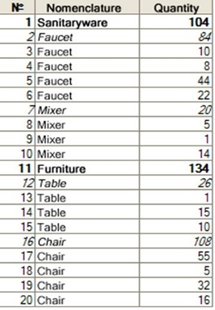
Fig. 393. Operational selection
In this table, we added the first column that is not included in the query text but will be used later to identify the record in the result. Totals records in the table are shown in italics, and totals values for hierarchical levels of the catalog are shown in bold.
8.5.1.2. Query result iteration methods
8.5.1.2.1. Linear result iteration
The linear method of result iteration is the simplest. Linear method selects records in the same sequence as in the query result. In our example, these will be records 1, 2, 3, 4, 5, and so on, up to 20.
To retrieve a linear selection from the result, call the Select() method of the QueryResult object with no parameters or with the QueryResultIteration.Linear parameter.
Example:
SelectionMethod = QueryResultIteration.Linear;
Selection1 = QueryResult.Select(SelectionMethod);
// which is equivalent
to the following line
Selection1 = QueryResult.Select();8.5.1.2.2. Hierarchical result iteration
The next method for result iteration is hierarchical. With this method, only records that are on the same level are iterated. To retrieve a hierarchical selection from the result, call the Select() method of the QueryResult object with the QueryResultIteration.ByGroupsWithHierarchy parameter.
Example:
SelectionMethod = QueryResultIteration.ByGroupsWithHierarchy;
Selection2 = QueryResult.Select(SelectionMethod);In our example, only records 1 and 11 will be selected by the selection from the result with hierarchical iteration, as these are the only two records on the highest level. To illustrate this, let us assume that our result is a tree, where summary records are nodes, and detailed records are leaves. Here is what we will get:
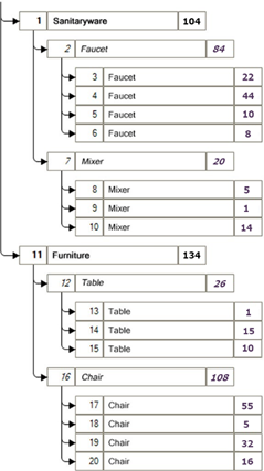
Fig. 394. Hierarchical query result iteration
From this figure, we can see that only records 1 and 11 are located at the first level of the tree and that only these records will be included in the first pass of hierarchical iteration.
The question is how to obtain the remaining records of the query result. To do this, it is possible to retrieve another selection from the QueryResultSelection object to be used for iteration over subordinate records of the current selection. In our example, when the Selection2 object is placed on the record number 1, we will request hierarchical selection from it. Thus, we will get a selection that will return records with numbers 2 and 7. And if Selection2 is placed on the record number 11, the resulting hierarchical selection will return records with numbers 12 and 16. This is how the hierarchical iteration for query results works.
Note, that it is possible to retrieve nested selections of any type from the selection. Thus, if we requested a linear selection from the Selection2 object, placed in record 1, it would return records from 2 to 10. Let us show an example of the above method.
Example:
Procedure ExecuteQuery()
// Creating a query.
Query = New Query;
// Set a query text
Query.Text = "SELECT
|SalesInvoiceContent.Products AS Products. |SalesInvoiceContent.Count AS Count
|FROM
|Document.SalesInvoice.Content AS SalesInvoiceContent
|ORDER BY
|SalesInvoiceContent.Products
|TOTALS
|SUM(Count)
|BY
|Products HIERARCHY";
// Running the query and writing the result to the
// QueryResult variable.
QueryResult = Query.Execute();
// Getting the query result selection.
Selection = QueryResult.Select(QueryResultIteration.ByGroupsWithHierarchy);
OutputRecursively(Selection);
EndProcedure
Procedure OutputRecursively(Selection)
// While the selection contains records...
While Selection.Next() Do
// ... displaying fields from the result to the message window
Product = Selection.Products;
Count = Selection.Count;
Message("Product: "+Product+" Count: " + Count);
// Going on with subordinate record selection
SelectionMethod = QueryResultIteration.ByGroupsWithHierarchy;
OutputRecursively(Selection.Select(SelectionMethod, Selection.Grouping()));
EndDo;
EndProcedure8.5.1.2.3. Result iteration by groups
The third method of result iteration is iteration by groups. It is similar to hierarchical iteration with one difference: records with hierarchical totals during iteration are treated as detailed records, rather than as totals records. To retrieve a selection by groups from the query result, call the Select() method of the QueryResult object with the QueryResultIteration.ByGroups parameter.
Example:
SelectionMethod = QueryResultIteration.ByGroups;
Selection2 = QueryResult.Select(SelectionMethod);
// After the last
iteration, the result will be records with numbers:
// 1, 2, 7, 11, 12, 16.Example:
Procedure ExecuteQuery()
// Creating a query.
Query = New Query;
// Set a query text
Query.Text = "SELECT
|SalesInvoiceContent.Products AS Products. |SalesInvoiceContent.Count AS Count
|FROM
|Document.SalesInvoice.Content AS SalesInvoiceContent
|ORDER BY
|SalesInvoiceContent.Products
|TOTALS
|SUM(Count)
|BY
|Products HIERARCHY";
// Running the query and writing the result to the
// QueryResult variable.
QueryResult = Query.Execute();
// Getting the query result selection
Selection = QueryResult.Select(QueryResultIteration.ByGroups);
// While the selection contains records...
While Selection.Next() Do
// ... displaying fields from the result to the message window
Product = Selection.Products;
Count = Selection.Count;
Message("Product: "+Product+" Total by product:
"+Count);
OutputChildRecords(Selection.Select());
EndDo;
EndProcedure
Procedure OutputChildRecords (Selection)
// While the selection contains records...
While Selection.Next() Do
// ... displaying fields from the result to the message window
Product = Selection.Products;
Count = Selection.Count;
Message("Product: "+Product+" Count: "+Count);
EndDo;
EndProcedure8.5.1.3. Operations with selection
The QueryResultSelection object is intended to iterate query result records. Selection is some object that contains a reference to the current result record and gives access to all the fields of the current record. Three methods are used for query record navigation:
-
Next(). Go to the next result record according to the selection iteration order. The selection is positioned on the first record at the first call. When all records are selected, this method will return the False value.
-
NextByFieldValue(). Get the next record with a value in the specified field that differs from the value in the same field of the current record.
-
FindNext(). Find a record with the specified values in certain fields.
8.5.1.3.1. Using the NextByFieldValue() method
This method can be used to group results by field values.
Example:
SELECT
Doc.Products, Doc.Ref.Counterparty AS Counterparty, Doc.Count
FROM
Document.SalesInvoice.Content AS Doc
ORDER BY
Doc.Products.Description, CounterpartyResult:
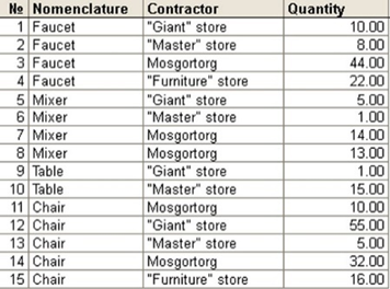
Fig. 395. Query result
We retrieve a linear selection from the query result and we will use the NextByFieldValue() method for iteration.
Example:
Selection = QueryResult.Select();
While Selection.NextByFieldValue("Products") Do
// here we get records 1, 5, 8, 11
While Selection.NextByFieldValue("Counterparty") Do
// here we first get records 1, 2, 3, 4
// then records 5, 6, 7
// then records 8, 9, 10
// then records 11, 12, 13, 14
EndDo;
EndDo;Note that if we use the Next() method to get records by field value in the cycle, all the records with the same field value specified during the previous call of the NextByFieldValue() method will be selected.
Example:
Selection = QueryResult.Select();
While Selection.NextByFieldValue("Products") Do
// here we get records 1, 5, 8, 11
While Selection.Next() Do
// here we first get records 1, 2, 3, 4
// then records 5, 6, 7
// then records 8, 9, 10
// then records 11, 12, 13, 14
EndDo;
EndDo;8.5.1.3.2. Methods for defining the current record type
When a selection is placed in a record, we can use this selection to get the attributes of the record. The following methods are used to get record attributes:
-
Level(). Determines a record level in the query result.
-
RecordType(). Determines whether a record belongs to one of the following types:
-
Group total
-
Total by hierarchy
-
Detailed record
-
Grand total
-
-
Grouping(). Determines a name of the field used to calculate totals.
To illustrate how these methods operate, let's see what they will return for a query that was used as an example in the beginning of the chapter.
SELECT
SalesInvoiceContent.Products AS Products, SalesInvoiceContent.Count AS Count
FROM
Document.SalesInvoice.Content AS SalesInvoiceContent
ORDER BY
SalesInvoiceContent.Products
TOTALS
SUM(Count)
BY
Products HIERARCHYResult:
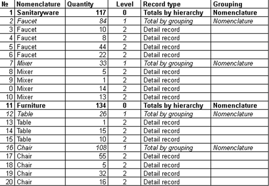
Fig. 396. Record hierarchy
8.5.2. Managing temporary tables
8.5.2.1. General information
Managing temporary tables is ensured by two components:
-
Query language syntax that allows creating new temporary tables and using the current ones (for details, see Temporary table).
-
The TempTablesManager object of 1C:Enterprise language that stores temporary table data. Contained in this section.
8.5.2.2. Temporary table manager
A temporary table manager is intended to manage the existence time of temporary tables created during the application operations.
Each application supports creation of multiple instances of temporary tables manager, where each of them stores its own set of temporary tables. Within a single temporary table manager, each temporary table must have a unique name that is also a temporary table ID.
Note. Note. Temporary table names must meet the requirements for names of 1C:Enterprise language variables (see Names of variables, procedures, and functions).
Temporary tables manager instance may be created using the New constructor.
Example:
TempTablesManager = New TempTablesManager;When a transaction is rolled back, all the temporary tables that were created during the transaction are deleted from the temporary table manager, and it is impossible to access them. Each temporary table created in a given manager instance exists until this temporary table manager instance exists. Deleting a temporary tables manager instance also deletes all the temporary tables contained in it.
Force a temporary tables manager to close with the Close() method. All the tables created in it will be deleted. Further operating this temporary tables manager instance is not possible.
8.5.2.3. Managing temporary tables
Temporary tables are created using Query object of 1C:Enterprise language.
A query is linked to a temporary tables manager using the TempTablesManager property of the query, which specifies the manager instance where the temporary tables must be created.
Example:
TempTablesManager = New TempTablesManager;
Query = New Query;
Query.TempTablesManager
= TempTablesManager;If a temporary table manager is not specified for a query, it means that temporary tables created within the query cannot be accessed outside that query. To use existing temporary tables in another query, follow these steps:
-
Set the temporary table manager to the Query object where temporary tables are generated.
-
After creating temporary tables, set the same temporary tables manager in the Query object, which will use the previously created temporary tables.
-
Now, you can access temporary tables in the "using" query by names that were set for them when the temporary tables were created.
To create a temporary table, use query language expressions. For more information on creating temporary tables, see Creating temporary tables.
8.5.2.4. Debugging a query with temporary tables
When debugging complex queries containing temporary tables, it becomes necessary to analyze the content of temporary tables. To do this, use the Query.ExecuteBatchWithIntermediateData() method (see Working with batch queries) or the temporary table manager.
Note. Note. The considered query has no application meaning, but serves solely to demonstrate the managing of temporary tables in the process of query debugging.
Consider an example of such use:
Query = New Query;
Query.TempTablesManager
= New TempTablesManager;
Query.Text = "SELECT
| SalesTurnover.Product, | SalesTurnovers.CountTurnover
|INTO Sales
|FROM
| AccumulationRegister.Sales.Turnovers
AS SalesTurnovers
|;
|
|///////////////////////////////// |SELECT
| InventoryBalance.Product, | InventoryBalance.CountBalance
|INTO Balance
|FROM
| AccumulationRegister.Inventory.Balance
AS InventoryBalance
|;
|
|///////////////////////////////// |SELECT
| Goods.Name, | Sales.CountTurnover, | Balance.CountBalance
|FROM
| Catalog.Goods AS Goods
| INNER JOIN Balance AS
Balance
| BY Goods.Ref = Balance.Product
| INNER JOIN Sales AS Sales
| BY Goods.Ref = Sales.Product";
Result = Query.Execute();
SalesVT = Query.TempTablesManager.Tables["Sales"].GetData().Export();
BalanceVT = Query.TempTablesManager.Tables[1].GetData().Export();As a result of the query, the Query.TempTablesManager.Tables property will contain a collection of temporary tables containing the results of the batch query. Using the Table property, it is possible to access each temporary table, and this can be done both by name and by index of the temporary table. For example, the value table SalesVT has been retrieved as a result of accessing the Sales temporary table by name (Tables ["Sales"]). At the same time, the generation of a value table BalanceVT is performed by accessing by index (Tables[1]).
8.5.3. Working with batch queries
1C:Enterprise platform allows you to use query batches (for details, see Batch query).
To execute a query batch, use the Query.Execute() method. This method will sequentially execute all the queries in the batch, and, as a result, return the result of the last resultant query in the batch. Under "resultant" we mean a query that creates, updates, or deletes a temporary table. If such query does not exist, the result of the last executed query will be returned. The Undefined value is the result of executing a query to delete a temporary table.
The Query.ExecuteBatch() method sequentially executes all the queries and returns an array of results for each query from the batch in the sequence of queries placed in the text of the batch. The result of the query for the dropping of a temporary table is the Undefined value, which is also placed in an array of results.
If it is necessary to debug a batch query, it is possible to use the ExecuteBatchWithIntermediateData() method. In this case, the result of the operation is similar to the ExecuteBatch() method with the difference that the temporary tables generated in the query batch will not be represented by the number of records in the corresponding temporary table (as when calling the ExecuteBatch() method), but by the contents of such temporary tables.
Thus, the query example can be as follows:
Query = New Query;
Query.Text = "SELECT
|ProductsAccountingBalanceAndTurnovers.Product, |ProductsAccountingBalanceAndTurnovers.CountReceipt, |ProductsAccountingBalanceAndTurnovers.CountExpense, |ProductsAccountingBalanceAndTurnovers.CountClosingBalance
|INTO ProductsAccounting
|FROM
|AccumulationRegister.Inventory.BalanceAndTurnovers(, , Auto, , )
AS ProductsAccountingBalanceAndTurnovers
|;
|
|SELECT
|ProductsAccounting.Product, |ProductsAccounting.CountExpense, |ProductsAccounting.CountClosingBalance
|FROM
|ProductsAccounting AS ProductsAccounting
|";
BatchResult = Query.ExecuteBatchWithIntermediateData();
TemporaryTable = BatchResult[0].Export();
Result = BatchResult[1].Export();In this case, the TemporaryTable variable will contain a value table with data of the ProductsAccounting temporary table. The Result variable will contain a temporary table with the result of the last batch query (the actual batch result).
8.5.4. Software operations with queries
1C:Enterprise application allows generating or modifying a query using 1C:Enterprise language. For this, there is a special QuerySchema object. Using the QueryBatch property, the developer gets access to all queries that are currently being edited using the QuerySchema object. The SetQueryText() method is used to populate the QuerySchema object based on the passed query text, and the GetQueryText() method is used for the inverse operation.
As an example of using the object model of working with queries, the program code needed to generate the following query is given:
SELECT
InventoryBalance.Product AS Product, InventoryBalance.Warehouse AS Warehouse, InventoryBalance.CountBalance AS CountBalance, CASE
WHEN InventoryBalance.CountBalance > 0 THEN "Sufficient"
ELSE "Insufficient"
END AS State
FROM
AccumulationRegister.Inventory.Balance AS InventoryBalance
WHERE
InventoryBalance.Warehouse = &Warehouse
ORDER BY
Product, Warehouse, CountBalance
TOTALS
SUM(CountBalance)
BY
OVERALL, Product, WarehouseCode in 1C:Enterprise language:
Wizard = New QuerySchema;
QuerySchemaQuery1 = Wizard.QueryBatch[0];
Operator1 = QuerySchemaQuery1.Operators[0];
// adding a source to
the query
RegisterTable = Operator1.Sources.Add("AccumulationRegister.Inventory.Balance", "InventoryBalance");
// adding fields to the
query
FieldProduct = Operator1.SelectedFields.Add("InventoryBalance.Product", 0);
AvailableFieldWarehouse
= RegisterTable.Source.AvailableFields.Find("Warehouse");
FieldWarehouse = Operator1.SelectedFields.Add(AvailableFieldWarehouse, 1);
FieldCount = Operator1.SelectedFields.Add("CountBalance", 2);
SelectionExpression = New QuerySchemaExpression("CASE
|WHEN
InventoryBalance.CountBalance > 0
| THEN "Sufficient"
| ELSE "Insufficient"
|END");
ComboBox = Operator1.SelectedFields.Add(String(SelectionExpression), 3);
// setting aliases
Result = QuerySchemaQuery1.Columns.Find(FieldCount);
Result.Alias = "CountBalance";
Result = QuerySchemaQuery1.Columns[1];
Result.Alias = "Warehouse";
Result = QuerySchemaQuery1.Columns.Find(SelectionExpression);
Result.Alias = "State";
// adding a condition
Operator1.Filter.Add(String(FieldWarehouse)
+ " = &Warehouse");
// adding ordering
QuerySchemaQuery1.Order.Add(FieldGoods);
QuerySchemaQuery1.Order.Add("Warehouse");
QuerySchemaQuery1.Order.Add("CountBalance");
// setting totals
checkpoints
QuerySchemaQuery1.Overalls
= True;
QuerySchemaQuery1.TotalCalculationFields.Add(FieldProduct);
QuerySchemaQuery1.TotalCalculationFields.Add("Warehouse");
// setting aggregate
functions for totals
ColumnCount = QuerySchemaQuery1.Columns.Find(FieldCount);
QuerySchemaQuery1.TotalExpressions.Add("Sum("
+ ColumnCount.Alias +")");
Text = Wizard.GetQueryText();The QuerySchema object supports the query extension for the data composition system. It is defined by the QuerySchema.DataCompositionMode property. If this property is set to True, the TotalExpressions, TotalCalculationFields, and Overalls properties of the QuerySchemaSelectQuery object become unavailable. If you set the query text using the QuerySchema.SetQueryText() method, the QuerySchema.DataCompositionMode property is set to True, and the query text contains the TOTALS clause, an exception will be thrown.
The client application allows opening the query editor during operation. To do it, use the QueryWizard object. To open the wizard, call the Show() method, where the callback handler must be passed. The callback will be performed after the query editing completion. You can open the query editor in two modes: query editing mode and query editing mode for the data composition schema. This behavior is managed using the QueryWizard.DataCompositionMode property. You can open a query text that is being edited or edited using the QueryWizard.Text property.
Chapter 9. Data operations
9.1. Transactions
9.1.1. General information
Regardless of the selected operation mode (file or client/server), 1C:Enterprise allows you to manage information stored in the database using transactions.
Transaction is an indivisible (in terms of impact on the database) sequence of data manipulation operations. It is executed on the "all or nothing" principle and transfers a database from one holistic state to another holistic state. If, for any reason, one of the transaction actions is not feasible or a system malfunction has occurred, the database returns to the state it had been in before the transaction began (the transaction is rolled back).
Transactions can be used both by 1C:Enterprise and the developer when writing modules.
1C:Enterprise defines an implicit transaction when performing any actions related to the modification of information stored in the database. For example, all event handlers located in object modules and record sets that are associated with modifying database data are called during a transaction. At the same time, reading database objects (accessing dot-separated object properties, executing the .GetObject() method, opening an object form or a record set) is performed outside the transaction to improve 1C:Enterprise operation parallelism. Within such reading, 1C:Enterprise ensures that the state of the read object in memory will be exactly as it was in the database at the time of the reading start. However, to ensure reading integrity, 1C:Enterprise can open implicit transactions whose occurrence conditions are described below.
Besides, the developer can use transaction operations explicitly. To do it, they can use the BeginTransaction(), CommitTransaction(), and RollbackTransaction() global context methods.
9.1.2. Using explicit transaction call
The BeginTransaction() method allows opening a transaction. After that, all database data changes performed by subsequent operators can be either fully accepted or fully rejected.
The CommitTransaction() method is used to accept all the changes made. To undo all the changes made in an open transaction, use the RollbackTransaction() method. If the number of the BeginTransaction() method calls exceeds the number of the CommitTransaction() or RollbackTransaction() method calls, 1C:Enterprise will execute the implicit RollbackTransaction() method call in the following cases:
-
At the end of 1C:Enterprise language execution (an event handler, an external connection, an automation server).
-
When passing control from the server to the client.
If the number of the CommitTransaction() or RollbackTransaction() method calls exceeds the number of the BeginTransaction() method calls, an exception is thrown when executing an extra call of the CommitTransaction() or RollbackTransaction() method.
So, the general transaction operation scheme might look as follows:
Try
BeginTransaction();
// Sequence of statements
... CommitTransaction();
Except
RollbackTransaction();
EndTry;When using this scheme, remember that not all errors that occur when operating with the database are handled in the same way.
In general, all database errors can be divided into two categories:
-
Non-recoverable
-
Recoverable
Non-recoverable errors are errors which prevent normal 1C:Enterprise functioning. For example, data might be corrupted when these errors occur. If a non-recoverable error occurs, 1C:Enterprise is terminated in any case.
If a non-recoverable error occurs during the transaction execution, all changes made within this transaction are canceled by the system.
Recoverable errors are errors that do not cause serious violations in 1C:Enterprise operation. If a recoverable error occurs, you can continue operating with the system. In this case, an operation that caused the error stops and an exception is thrown. It can be caught and handled by the Try ... Except ... EndTry structure.
If a recoverable error occurs when executing a transaction, 1C:Enterprise does not automatically cancel the transaction, giving the developer a chance to handle the situation.
Depending on the nature of the error that occurred, various scenarios for handling such situation are possible.
If an error is not related to the database, the transaction and module operation can be continued. If necessary, the developer can cancel the transaction or continue it if the error does not violate the atomic nature of the transaction.
If the exception is caused by a database error, the system records an error in this transaction, and further operation with the transaction or its commitment becomes impossible. The only database operation that the developer can perform in this situation is to cancel the transaction. After that, they can try executing this transaction again.
For example, a code snippet that implements this approach when writing data to the database might be as follows.
// Write attempts
completion flag
Written = False;
// Write attempts are
performed in a loop
While Not Written Do
Try
BeginTransaction();
Data.Write();
CommitTransaction();
// In case of committing a transaction stop write attempts
Written = True;
Except
// If unsuccessful, cancel the current transaction and
// start the next attempt with a new transaction
RollbackTransaction();
EndTry;
EndDo;9.1.3. Nested transaction call
You can call the BeginTransaction(), CommitTransaction(), and RollbackTransaction() procedures within a running transaction. For example, the following call pattern can be used:
BeginTransaction();
…
// Nested transaction call
BeginTransaction();
... CommitTransaction();
…
// Nested transaction call
BeginTransaction();
... CommitTransaction();
…
CommitTransaction();However, such call does not mean starting a new transaction within an already running one.
Note. WARNING! 1C:Enterprise does not support nested transactions.
This means that only a top-level transaction is always valid. All the transactions that are called inside an already open transaction are actually related to the same transaction and do not form a nested transaction. So, if you cancel changes in a nested transaction, it cancels all changes of the top-level transaction rather than only changes of the nested transaction. At the same time, committing changes made in a nested transaction is ignored.
9.1.4. Transaction impact on software object operation
In general, software objects used by 1C:Enterprise are absolutely "transparent" for database transactions. In other words, database transactions can be called when executing various methods of software objects. However, for example, actions performed by the database when a transaction is rolled back generally do not affect respective software objects in any way.
When canceling database transactions, the developer (if necessary) must independently provide an adequate change in data of respective software objects. They can do it by re-reading all object data or by changing certain attributes of a software object (for example, if it is required to display the object in the interface).
There are exceptions to this rule. Due to significant applied nature of 1C:Enterprise software objects, rollback of changes made in the database can sometimes affect property values of respective software objects. This happens in the following cases:
-
When a transaction is canceled, the document posting flag restores the value it had before the transaction start.
-
If an object is created and recorded in a transaction, the reference value is cleared when the transaction is rolled back.
-
If an object is created outside the transaction and an automatically generated code/number is used when writing the object in the transaction, the code/number is cleared when the transaction is canceled.
9.2. Locks
9.2.1. General information
When operating with a database, there are often situations when several users need to change the same database record. If special system features are not used in such cases, issues may arise related to the integrity and reliability of the data stored in the infobase. Such special feature is data locks.
The data lock is actually information that some database object is locked to perform some actions by some consumer (user, session, and so on). As a result of using locks, other users cannot use the locked object until the lock set by another user is removed. Thus, locks ensure competitive access to database data and consistency of the data stored in this database.
1C:Enterprise has object locks and transaction locks. Object locks allow competitive access of various users to 1C:Enterprise data in terms of infobase objects. As a rule, it relates to interactive user operations in forms: editing and deleting existing objects, creating new ones, and so on. To ensure consistent changes to data, the DBMS uses transactions, and to ensure competitive access to data, it uses transaction locks.
9.2.2. Object locking
9.2.2.1. General information
When operating with object data (catalogs, documents, accounts, and so on), 1C:Enterprise provides two types of object locking: pessimistic and optimistic. They allow you to make holistic changes to objects when several users are operating simultaneously.
9.2.2.2. Pessimistic locking
Pessimistic locking of database objects is used to prevent other sessions or the current session from changing object data until the locking is released (automatically or using 1C:Enterprise language methods).
Basically, pessimistic locking is used in 1C:Enterprise to lock objects that are being edited in the form. At the same time, the developer can apply this feature by means of 1C:Enterprise language.
1C:Enterprise applies pessimistic locking using extensions of applied object forms. When the user begins modifying an object in a form, the form extension sets a pessimistic lock. When the user editing the object closes the object form, the form extension will remove the pessimistic lock. If another user (or the same user but from another session) attempts to start editing the same object, the system will notify them about it. Several solutions can be offered depending on the situation:
-
In file mode:
-
The collaboration system is unavailable: detailed information on the user who has locked the object is displayed.
-
The collaboration system is available: the information on the user who has locked the object is displayed and editing is enabled. If you start editing, the changes made in another session will be lost.
-
If the object is locked by another user, you can send a message to this user using the collaboration system.
-
Client/server mode:
-
If the object is locked by the same user in another session, you can start editing with the loss of changes made in the other session.
-
If the object is being edited by another user, you can start editing it with the loss of changes made by the other user. In this case, you can send a message to this user if the collaboration system is available.
-
If you need to provide the same behavior in a non-standard object form as in a standard object form, you can use the LockFormDataForEdit() form method to enable the pessimistic lock and the UnlockFormDataForEdit() form method to remove it.
To enable the pessimistic lock, the developer can use the LockDataForEdit() global context method. There are two options for setting a pessimistic lock:
-
Form ID is specified: the lock is active for the form lifetime. When the form is closed, the lock will be removed immediately if a normal connection is used, or after some time if a slow connection is used. In the following cases, the form is unlocked immediately:
-
End of the session in which the form is opened.
-
1 minute has elapsed after the form modification attribute was cleared.
-
During the form display, other locks have been enabled on behalf of this form (in case of interactive editing or using the LockFormDataForEdit() method).
-
The form on whose behalf background jobs (search in the dynamic list or report generation) were started is closed.
-
The UnlockDataForEdit() global context was used with the same form ID that was specified to set the lock.
-
-
Form ID is not specified: lock to be enabled is not bound to any form. The lock will be automatically removed at the end of the session, when control returns from the server, or at the end of the transaction (if the lock was set in the transaction). You can also remove the lock using the UnlockDataForEdit() global context method without specifying a form ID.
Note that locking does not prevent an object in the database from being modified or deleted. To ensure that a locked object cannot be modified, make an attempt to lock this object before changing it in another session. Locking a locked database object throws an exception that can be handled by the Try ... Except ... EndTry structure.
&AtServer
Function ModificationExample()
GoodsRef = Catalogs.Goods.FindByCode("000000001");
Try
LockDataForEdit(GoodsRef);
// Object data can be
modified
// ...
GoodsObject = GoodsRef.GetObject();
GoodsObject.Description = "New name";
GoodsObject.Write();
Return True;
Except
// Object data cannot be
modified
Message = New UserMessage;
Message.Text = "Object
data is already locked";
Message.Message();
Return False;
EndTry;
EndFunctionNote that attempts to lock the same object with and without specifying a form ID are incompatible with each other.
GoodsRef = Catalogs.Products.FindByCode(1);
LockDataForEdit(GoodsRef);
Try
LockDataForEdit(GoodsRef, , FormID);
Except
// exception due to locking
incompatibility
EndTry;To remove a pessimistic lock, the developer can use the UnlockDataForEdit() global context method.
See also:
- Collaboration system (see Collaboration system).
9.2.2.3. Pessimistic lock and transactions
Object locking operations only affect the execution of other object locking operations and do not affect data operations or the transaction flow process.
Locking a locked database object throws an exception that can be handled and does not necessarily cause the transaction rollback. If an exception is thrown in a transaction during the execution of the LockDataForEdit() method, it can be handled by the Try ... Except ... EndTry structure and does not require transaction rollback.
Object locks that are set during a transaction are removed at the end of the transaction if the lock is set without specifying a form ID.
9.2.2.4. Optimistic locking
Optimistic locking prevents an object from being written to the database if the object is modified in the database after reading. Optimistic locking is a check that is performed before an object is written to the database.
When 1C:Enterprise language object reads data from the database, it also reads the version of an object stored in the database. If object data in the database is changed (for example, by another user) before a user starts editing the data (before pessimistic lock is enabled), the version number of the object stored in the database also changes. When a user attempts to write this object, the application checks whether the version of the object in memory matches the version of the object stored in the database. As the versions differ, the system warns that the object version has changed or the object has been deleted. It means that optimistic locking will be activated.
Optimistic locking ensures that if a user changes an object, its changes will not "overwrite" the changes made by other sessions or software objects of the same session.
9.2.3. Managed locks
9.2.3.1. General information
Ideally, transactions in any DBMS must provide isolation of changes performed in the database. In other words, multiple transactions that perform data modification must not interfere with each other.
The easiest way to solve this problem is sequential execution of transactions. Each following transaction is executed after the previous one is completed.
However, in a real situation, in case of multi-user operation, this approach leads to a sharp decrease in 1C:Enterprise performance. Therefore, in practice, features that allow to perform multiple transactions simultaneously are used.
To make simultaneous execution of transactions possible, several levels of transaction isolation are used. At the lowest isolation level, transactions can strongly influence each other. At the highest level, they are completely isolated.
Thus, you have to pay for more transaction isolation with high overheads and system slowdowns.
The possibility to isolate certain transactions from others is usually implemented through locks set for the data they use. Depending on the isolation level, different types of locks are enabled for different database objects for different periods of time.
From 1C:Enterprise point of view, data operations can be performed in one of the following modes:
-
In the transaction
-
Outside the transaction
The outside the transaction data operation mode allows data reading operations only. This mode is introduced to ensure parallel data reading with maximum speed. Therefore, any data reading operation performed outside the transaction is considered irresponsible. This means that such reading operation might return obsolete data or even uncommitted changes made by another transaction. Reading is performed without consideration of data locks enabled by other transactions.
The "In the transaction" data operation mode allows any data reading and modifying operations.
The following rules must be observed:
-
Data reading must be reproducible. It means that any subsequent data reading operation with the same selection condition must return the same result.
-
The reading result must contain the most up-to-date data. This means that no other transaction can change data that is read in this transaction until the transaction has been completed.
-
The reading result must not contain uncommitted changes of the database data.
9.2.3.2. Managed locks
With 1C:Enterprise, you can use two modes of working with a database within a transaction: automatic lock mode and managed lock mode.
The main difference between these modes is as follows. The automatic lock mode does not require the developer to take any action to manage locks in a transaction to ensure compliance with the above rules for data operation in a transaction. Compliance with these rules is provided by 1C:Enterprise platform by means of certain levels of transaction isolation in a particular DBMS. This operation mode is the easiest for the developer. However, in some cases (for example, with intensive simultaneous operations of numerous users), the transaction isolation level in the DBMS cannot provide sufficient operation parallelism, which results in numerous lock conflicts during user operations.
In the managed lock mode, 1C:Enterprise uses a much lower level of transaction isolation in the DBMS, which can significantly increase the parallelism of application user operations. However, in contrast to the automatic lock mode, this transaction isolation level can no longer ensure that all the rules for data operations in a transaction are met (in particular, the reproducibility of data reading in a transaction is not ensured). Therefore, in the managed mode, the developer must manually manage locks to be enabled in a transaction.
Differences between the automatic lock mode and the managed lock mode are summarized in the table below:
| Lock kind | Transaction isolation level | |
|---|---|---|
| Automatic locks | ||
| File DB | Tables | Serializable |
| MS SQL Server | Records | Repeatable Read or Serializable |
| IBM Db2 | Records | Repeatable Read or Serializable |
| PostgreSQL | Tables | Serializable |
| Oracle Database | Tables | Serializable |
| Managed locks | ||
| File DB | Tables | Serializable |
| MS SQL Server 2000 | Records | Read Committed |
| MS SQL Server 2005 or later | Records | Read Committed Snapshot |
| IBM Db2 | Records | Read Committed |
| PostgreSQL | Records | Read Committed |
| Oracle Database | Records | Read Committed |
Note. Note. Application development in the managed lock mode is preferred to use DBMS features to their full extent. Using the application in automatic mode is used for compatibility with previous application versions and is not recommended for real-world operation.
The 1C:Enterprise behavior during irresponsible reading (for example, when dynamic lists are running, reports are executed) also differs in different lock modes. The differences between irresponsible reading in different lock modes (automatic or managed) when operating with objects that do not have tables are shown in the following table:
| Reading Outside the transaction | |
|---|---|
| Automatic locks | |
| File DB | "Dirty" read |
| MS SQL Server | "Dirty" read |
| IBM Db2 | "Dirty" read |
| PostgreSQL | Consistent read |
| Oracle Database | Consistent read |
| Managed locks | |
| File DB | "Dirty" read |
| MS SQL Server 2000 | "Dirty" read |
| MS SQL Server 2005 or later | Consistent read |
| IBM Db2 below version 9.7 | "Dirty" read |
| IBM Db2 version 9.7 or later | Consistent read |
| PostgreSQL | Consistent read |
| Oracle Database | Consistent read |
Irresponsible reading of objects with tables and record sets is always consistent. For this, the platform can define an implicit transaction and enable implicit managed locks:
| Implicit transaction | |
|---|---|
| Automatic locks | |
| File DB | Yes |
| MS SQL Server | Yes |
| IBM Db2 | Yes |
| PostgreSQL | No |
| Oracle Database | No |
| Managed locks | |
| File DB | Yes |
| MS SQL Server 2000 | Yes |
| MS SQL Server 2005 or later | Yes. In version 8.2.16 and earlier compatibility mode No. In version 8.2.17 and later compatibility mode |
| IBM Db2 | Yes |
| PostgreSQL | No |
| Oracle Database | No |
When reading an object with tables without an implicit transaction, the object version is read twice in the managed lock mode (the DataVersion object field): at the beginning and at the end of reading. If the versions differ, a transaction lock error occurs.
Information register record sets are always read in an implicit transaction. At the same time, in the managed lock mode, a shared lock is enabled by the recorder value. For an independent information register, a shared lock is enabled by the main filter values.
9.2.3.3. Setting the lock mode in the configuration
The configuration has the Data lock management mode property. Each applied configuration object also has the Data lock management mode property.
You can set the data lock management mode for the entire configuration to Automatic, Managed (set by default for the new configuration), and Automatic and managed. The Automatic or Managed values mean that this lock mode will be used for all configuration objects regardless of values set for each individual object. The Automatic and managed value means that the mode of each configuration object is taken from its Data lock management mode property: Automatic or Managed.
Consider that the data lock management mode specified for a metadata object is set for those transactions that are initiated by 1C:Enterprise when working with data of this object (for example, when modifying the object data).
For example, if an object writing operation is performed in a transaction initiated by the developer (the BeginTransaction() method), the data lock management mode will be determined by the value of the LockMode parameter of the BeginTransaction() method and not by the value of the Data lock management mode metadata object property.
By default, the LockMode parameter is set to DataLockControlMode.Automatic. So, to use the managed lock mode in an explicit transaction, set this parameter value to DataLockControlMode.Managed.
9.2.3.4. Operations with managed locks using 1C:Enterprise language tools
managed locks using 1C:Enterprise language toolsTo manage locks in a transaction, use the DataLock object of 1C:Enterprise language. You can create an object instance using the constructor. The instance allows you to describe required lock spaces and modes. To enable all the created locks, use the Lock() method of the DataLock object. If this method is running in an explicit or implicit transaction, locks are enabled to be automatically removed at the end of the transaction. If the Lock() method is executed outside the transaction or in the automatic lock management mode in the transaction, an exception will be thrown.
The DataLock object is a collection of data lock elements, each of which describes locks of one lock space. Lock spaces are defined in 1C:Enterprise platform and correspond to the structure of applied configuration objects. For each lock space in the platform, field names are defined. Field values can be analyzed when enabling certain locks.
The following lock space names and lock space field names are allowed:
| Lock space name | Lock space field name |
|---|---|
| Catalog.<name> | Ref; <field name> |
| Document.<name> | Ref; <field name> |
| ExchangePlan.<name> | Ref; <field name> |
| ChartOfAccounts.<name> | Ref; <field name> |
| BusinessProcess.<name> | Ref; <field name> |
| Task.<name> | Ref; <field name> |
| ChartOfCalculationTypes.<name> | Ref; <field name> |
| ChartOfCharacteristicTypes.<name> | Ref; <field name> |
| InformationRegister.<name>.RecordSet Only for an information register subordinate to the recorder | Recorder |
| InformationRegister.<name> | Period (if any) <dimension name> |
| AccumulationRegister.<name>.RecordSet | Recorder |
| AccumulationRegister.<name> | Period; <dimension name> |
| AccountingRegister.<name>.RecordSet | Recorder |
| AccountingRegister.<name> | Period; <dimension name>; <record type> is a value of the AccountingRecordType system enumeration; Account; ExtDimensions<N>; <extra dimension type> |
| CalculationRegister.<name>.RecordSet | Recorder |
| CalculationRegister.<name> | RegistrationPeriod; ActionPeriod; <dimension name> |
| Recalculation.<name>.RecordSet | RecalculationObject |
| Sequence.<name>.RecordSet | Recorder |
| Sequence.<name> | <dimension name> |
| Constant.<name> | |
| ExternalDataSource..Table.<Table name> | Ref; <field name> |
Where <field name> is a name of a field for which the managed lock can be enabled. You can specify a list of fields for which a managed lock can be set in the Data lock fields property for the following objects:
-
Catalogs
-
Documents
-
Charts of characteristic types
-
Charts of accounts
-
Charts of calculation types
-
Exchange plans
-
Business processes
-
Tasks
-
External data source tables
It is not allowed to enable locks for attributes and common attributes of the following types: string of unlimited length, value storage, value type of a chart of characteristic types, and union types that include one of the types mentioned above. You cannot enable locks for the following objects: catalogs, documents, charts of characteristic types, charts of calculation types, charts of accounts, business processes, tasks, and exchange plans. It is also forbidden to enable locks for the Predefined and PredefinedDataName fields in catalogs, charts of calculation types, charts of calculation types, and charts of accounts.
When you enable the managed transaction lock for the AccountingRegister.<Name> space and the extra dimension value is specified as a reference to a characteristic, this characteristic in the chart of accounts must be one of the extra dimensions of this account. If the corresponding extra dimension is not specified for the account, an error will be generated.
For each lock space, an arbitrary number of conditions can be specified for the fields, which will determine the records to be locked. Conditions are set to whether the field value is equal to the specified value or whether the field value is within the specified range. Conditions can be defined in two ways:
-
By explicitly specifying the field name and value (the SetValue() method of the DataLockItem object)
-
By specifying a data source containing required values (the DataSource property of the DataLockItem object).
When you explicitly specify a field value, the field name and value are passed to the parameters of the SetValue() method:
Lock = New DataLock;
LockItem = Lock.Add("Catalog.Store");
LockItem.SetValue("Code", 100);
LockItem.Mode = DataLockMode.Exclusive;
Lock.Lock();
Lock = New DataLock;
LockItem = Lock.Add("AccumulationRegister.GoodsInWarehouses");
LockItem.SetValue("Quality", Catalogs.Quality.FindByCode("1"));Note that the same register record can be locked twice: the first time by locking the record itself, and the second time by locking a set to which this record belongs.
When deleting or changing an object for which a field lock is available, one lock is performed, which includes a lock by the Link field and by all fields specified in the Data lock fields property. When being changed, an object is locked both by "old" field values (which were effective before the writing start) and by "new" values (which are in the object to be written).
Besides, a value can be the Range object of 1C:Enterprise language, which is created using the constructor. The object allows you to specify the range top and bottom limits (they are included in the range).
When using a data source, the value of the DataSource property is set, and then, using the UseFromDataSource() method, the lock area fields are set to match the data source fields:
Lock = New DataLock;
LockItem = Lock.Add("AccumulationRegister.GoodsInWarehouses");
LockItem.DataSource = DocumentObject.ReusablePackage;
LockItem.UseFromDataSource("Products", "Products");
LockItem.UseFromDataSource("Warehouse", "Warehouse");The following objects can be data sources:
-
Query result
-
Table
-
Record set
-
Value table
Accordingly, when matching the fields, the names of the source fields will be:
-
Query result column names
-
Table attribute names
-
Dimension names
-
Value table column names
The Range object can also be the value of a data source field.
For each lock item, one of the following lock modes can be set:
-
Shared
-
Exclusive
The lock mode is set using the Mode property of the DataLockItem object.
The managed lock compatibility table is as follows:
| Shared | Exclusive | |
| Shared | + | - |
| Exclusive | - | - |
The shared lock mode implies that locked data cannot be changed by another transaction until the end of the current transaction.
The exclusive lock mode implies that locked data cannot be changed by another transaction until the end of the current transaction, and also cannot be read by another transaction that enables a shared lock for this data.
As for the compatibility of actions performed in a transaction, note that besides explicit managed locks enabled by the user, 1C:Enterprise enables implicit managed exclusive locks when writing data in a transaction. When reading object data from the database (retrieving the object and accessing the reference), the transaction lock of the object is not performed. If the lock is required, enable it by means of 1C:Enterprise language before accessing the object.
Thus, the compatibility table for actions performed in a transaction when using managed lock mode looks as follows.
| Lock | Mode | NL | SL | EL | |||
|---|---|---|---|---|---|---|---|
| R | W | R | W | R | W | ||
| NL | R | + | + | + | + | + | + |
| W | + | - | - | - | - | - | |
| SL | R | + | - | + | - | - | - |
| W | + | - | - | - | - | - | |
| EL | R | + | - | - | - | - | - |
| W | + | - | - | - | - | - |
Where:
-
R – read
-
W – write
-
NL – no lock
-
SL – shared lock
-
EL – exclusive lock
9.2.3.5. "Automatic and managed" mode
Automatic and managed lock management mode is used to solve issues that arise during concurrent operations with separate configuration objects.
For example, there is a large configuration that is difficult to switch to managed lock mode at one time, but there are one or two documents which can cause problems when a large number of users work with them simultaneously. In this case, the entire configuration can be switched to the Automatic and managed mode and the document and configuration objects affected when it is written can be switched to the Managed mode. This will allow you to operate with this document in managed lock mode, while the main part of the configuration will continue to function in automatic lock management mode.
In the Automatic and managed lock management mode, consider the following features:
-
Regardless of the mode specified for this transaction, 1C:Enterprise will enable appropriate managed locks.
-
The lock management mode is determined by the transaction of the "highest" level. If another transaction is started by the current transaction start, the transaction to be started can be executed only in the mode that is set for the transaction that is already running.
Let us review these features in more detail.
The first feature: even if the automatic lock management mode is used for a transaction, 1C:Enterprise will additionally enable respective managed locks when writing data in this transaction. So, transactions that are executed in the managed lock mode might conflict with transactions that are executed in the automatic lock management mode.
The second feature: a lock management mode specified for a metadata object in the configuration or explicitly specified at the start of a transaction (as a parameter of the BeginTransaction() method) is just a "desired" mode. The actual lock management mode in which a transaction will be executed depends on whether this transaction start call is the first one or another transaction has already been started in this 1C:Enterprise session by this time.
For example, if you need to manage locks when writing register record sets and posting a document, set the managed lock mode both for the register and the document. Register record sets will be written in the transaction opened when writing the document.
There are four combinations of transaction lock management modes, which are given in the following table:
| Existing transaction mode | Started transaction mode | Result |
|---|---|---|
| Automatic | Automatic | The started transaction will be executed in the automatic mode. |
| Automatic | Managed | The started transaction will be executed in the automatic mode. |
| Managed | Automatic | An exception will be thrown. |
| Managed | Managed | The started transaction will be executed in the managed mode. |
9.2.3.6. Using numerous managed locks
Note that if more than 100,000 locks are used in one space, lock escalation might occur. In this case, the entire space is locked. When using independent separators, escalation occurs for one set of separator values:
-
The entire space is locked only within separator values.
-
Sessions with different separator values are not affected by escalation.
When using managed locks, remember that 1C:Enterprise can take over enabled locks. A lock where values of not all lock space dimensions are specified will take over a lock where values of a larger number of lock space dimensions are specified, provided that values for the same dimensions match lock spaces. Both locks enabled by means of 1C:Enterprise language using the DataLock.Lock() method and locks enabled by the platform can be taken over.
For example, if the accumulation register has the Warehouse and Products dimensions, a lock which only has the Warehouse dimension will take over any locks that have both of the dimensions (Warehouse and Products).
If a transaction with numerous managed locks which differ by one dimension value is used, it is recommended that you enable only one managed lock for which the value of the different dimension will not be set.
If a conflict with already enabled locks occurs during lock escalation, escalation is not performed. Instead, an attempt to enable the requested lock is made. In this case, more than 100,000 locks per space might be enabled in 1C:Enterprise.
9.2.3.7. Modifying configurations during the transition to the managed lock mode
9.2.3.7.1. General information
During the transition to partial or full operation in the managed lock mode, the application needs improvement. To improve the application, you need to identify code snippets that require managed locks and set the required managed data lock mode in them. To do it, you can:
-
Use the DataLock object.
-
Use the LockForUpdate property of record sets in accumulation registers and accounting registers. The required managed lock will be automatically enabled by the platform for register record sets where this property is set to True.
9.2.3.7.2. Identifying code snippets that require improvement
Managed locks must be set in code snippets that meet one of the following conditions:
-
Data to be changed in the future is read.
-
A consistent data set (contained in several objects) is read and the consistency of the read data must be maintained. In this case, data from this set must be locked either before reading or while reading separate elements. If a data element is read once, not connected logically with the other data elements, and will not be changed in the same transaction, it does not have to be locked.
-
It is important to ensure that the data to be read remains unchanged until the end of the transaction. For example, some data to be read in a transaction can be read again. It is important to ensure that it remains unchanged.
A typical example of such operations may be a query for product balances in the document posting module.
9.2.3.7.3. Selecting a managed lock mode
For the operations described above, a lock mode must be set based on the following factors:
-
Exclusive lock mode must be set for data that must be changed within the same transaction. This will prevent lock conflicts.
-
Shared lock mode must be set for data that is only read and is not supposed to change but still must be locked from modification.
9.2.3.7.4. Configuration improvement examples
Below, there is an example of how to enable managed locks in the record set module of the GoodsInWarehouses accumulation register.
First of all, create a managed lock:
Lock = New DataLock;Analyze a query text that is generated in the module and create required locks.
Exclusive lock of the "GoodsInWarehouses" register
When executing the record set module, a query with the following code snippet is generated:
// …
LEFT JOIN
AccumulationRegister.GoodsInWarehouses.Balances(, Products IN (SELECT DISTINCT
Products
FROM
Document.GoodsServicesSale.Goods
WHERE
Ref = &DocumentRef))
// …In this case, set the following locks:
LockGoodsInWarehouses1
= Lock. Add("AccumulationRegister.GoodsInWarehouses");
LockGoodsInWarehouses1.Mode
= DataLockMode.Exclusive;
LockGoodsInWarehouses1.DataSource
= DocumentObject.Goods;
LockGoodsInWarehouses1.UseFromDataSource("Products", "Products");
LockGoodsInWarehouses1.UseFromDataSource("ProductsCharacteristic", "ProductsCharacteristic");
LockGoodsInWarehouses1.UseFromDataSource("Warehouse", "Warehouse");Shared lock of the "GoodsReservedInWarehouses" register
When executing the module, a query with the following code snippet is generated:
// …
LEFT JOIN
AccumulationRegister.GoodsReservedInWarehouses.Balances(, Products IN (SELECT DISTINCT
Products
FROM
Document.GoodsServicesSale.Goods
WHERE
Ref = &DocumentRef))
// …In this case, set the following locks:
LockGoodsReservedInWarehouses1
= Lock.Add("AccumulationRegister.GoodsReservedInWarehouses");
LockGoodsReservedInWarehouses1.Mode
= DataLockMode.Shared;
LockGoodsReservedInWarehouses1.DataSource
= DocumentObject.Goods;
LockGoodsReservedInWarehouses1.UseFromDataSource("Products", "Products");
LockGoodsReservedInWarehouses1.UseFromDataSource( "ProductsCharacteristic", "ProductsCharacteristic");
LockGoodsReservedInWarehouses1.UseFromDataSource("Warehouse", "Warehouse");Shared lock of the "GoodsForTransferFromWarehouses" register
When executing the module, a query with the following code snippet is generated:
// …
LEFT JOIN
AccumulationRegister.GoodsForTransferFromWarehouses.Balances(, Products IN (SELECT DISTINCT
Products
FROM
Document.GoodsServicesSale.Goods
WHERE
Ref = &DocumentRef))
// …In this case, set the following locks:
LockGoodsForTransferFromWarehouses1
= Lock.Add("AccumulationRegister.GoodsForTransferFromWarehouses");
LockGoodsForTransferFromWarehouses1.Mode
= DataLockMode.Shared;
LockGoodsForTransferFromWarehouses1.DataSource
= DocumentObject.Goods;
LockGoodsForTransferFromWarehouses1.UseFromDataSource("Products", "Products");
LockGoodsForTransferFromWarehouses1.UseFromDataSource("ProductsCharacteristic", "ProductsCharacteristic");
LockGoodsForTransferFromWarehouses1.UseFromDataSource("Warehouse", "Warehouse");Locks by the "ReusablePackage" table. Exclusive lock of the "GoodsInWarehouses" register
When executing the module, a query with the following code snippet is generated:
// …
LEFT JOIN
AccumulationRegister.GoodsInWarehouses.Balances(, Products IN (SELECT DISTINCT
Document.GoodsServicesSale.ReusablePackage.Products
FROM
Document.GoodsServicesSale.ReusablePackage
WHERE
Document.GoodsServicesSale.ReusablePackage.Ref = &DocumentRef)
AND Quality = &New)
// …In this case, set the following locks:
LockGoodsInWarehouses2
= Lock.Add("AccumulationRegister.GoodsInWarehouses");
LockGoodsInWarehouses2.Mode
= DataLockMode.Exclusive;
LockGoodsInWarehouses2.DataSource
= DocumentObject.ReusablePackage;
LockGoodsInWarehouses2.UseFromDataSource("Products", "Products");
LockGoodsInWarehouses2.UseFromDataSource("Warehouse", "Warehouse");
LockGoodsInWarehouses2.SetValue("Quality", Catalogs.Quality.FindByCode("1"));Locks by the "ReusablePackage" table. Shared lock of the "GoodsReservedInWarehouses" register
When executing the module, a query with the following code snippet is generated:
// …
LEFT JOIN
AccumulationRegister.GoodsReservedInWarehouses.Balances(, Products IN (SELECT DISTINCT
Document.GoodsServicesSale.ReusablePackage.Products
FROM
Document.GoodsServicesSale.ReusablePackage
WHERE
Document.GoodsServicesSale.ReusablePackage.Ref = &DocumentRef)) AS Reserves
// …In this case, set the following locks:
LockGoodsReservedInWarehouses2
= Lock.Add("AccumulationRegister.GoodsReservedInWarehouses");
LockGoodsReservedInWarehouses2.Mode
= DataLockMode.Shared;
LockGoodsReservedInWarehouses2.DataSource
= DocumentObject.ReusablePackage;
LockGoodsReservedInWarehouses2.UseFromDataSource("Products", "Products");
LockGoodsReservedInWarehouses2.UseFromDataSource("Warehouse", "Warehouse");Locks by the "ReusablePackage" table. Shared lock of the "GoodsForTransferFromWarehouses" register
When executing the module, a query with the following code snippet is generated:
// …
LEFT JOIN
AccumulationRegister.GoodsForTransferFromWarehouses.Balances(, Products IN (SELECT DISTINCT
Document.GoodsServicesSale.ReusablePackage.Products
FROM
Document.GoodsServicesSale.ReusablePackage
WHERE
Document.GoodsServicesSale.ReusablePackage.Ref = &DocumentRef)) AS GoodsForTransfer
// …In this case, set the following locks:
LockGoodsForTransferFromWarehouses2
= Lock.Add("AccumulationRegister.GoodsForTransferFromWarehouses");
LockGoodsForTransferFromWarehouses2.Mode
= DataLockMode.Shared;
LockGoodsForTransferFromWarehouses2.DataSource
= DocumentObject.ReusablePackage;
LockGoodsForTransferFromWarehouses2.UseFromDataSource("Products", "Products");
LockGoodsForTransferFromWarehouses2.UseFromDataSource("Warehouse", "Warehouse");After all the necessary locks have been created, lock the listed data:
Lock.Lock();
// ... followed by the
old text of the module9.3. Exclusive mode
Exclusive mode is a specific database access mode in which you can perform operations with the database using only one session. You can use the exclusive mode to make significant coordinated changes to the infobase that do not need to be performed within a transaction. At the same time, it is desirable to exclude the effect of other sessions on the change results. The exclusive mode is required for certain 1C:Enterprise language methods (for example, the DeleteObjects() method) and Designer.
To set or disable the exclusive mode, use the SetExclusiveMode() global context method. To check whether the exclusive mode is set, use the ExclusiveMode() method. You cannot change the exclusive mode state if an explicit or implicit transaction is active.
A session can set the exclusive mode if there are no other sessions with this infobase. In the exclusive mode, you cannot create new sessions with this infobase except for starting one background job. If a background job is started from the session that set the exclusive mode, the started background job will "take away" the exclusive mode from the parent session. During the background job execution, the parent session cannot change data in the infobase. The exclusive mode will "return" to the parent session after the running background job is completed.
In the exclusive mode, managed locks are not enabled and attempts to enable them are ignored.
If the exclusive mode is set in the session, a warning that a database is locked will be displayed when you try to start the client application. You will also be able to restart the client application in the dialog box.
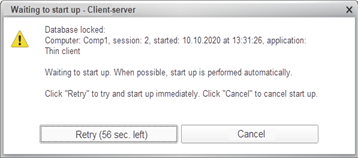
Fig. 397. Information on the infobase lock
This dialog box does not explain the reason for locking. This is a useless message for users, especially if they do not have access to administration tools of the infobase or the server cluster.
To inform the user why the exclusive mode is set programmatically, use the Parameters parameter of the SetExclusiveMode() method. The parameter value is an object of the ExclusiveModeParameters type that has the Message property. You can place a text message in this property. This message will allow you to describe the reason for setting the exclusive mode so that it is clear to the user. A text message can be either a plain text string (a value of the String type) or a formatted string (a value of the FormattedString type).
Consider an example. The application sets the exclusive mode because the infobase must be updated. To do it, execute the following code in 1C:Enterprise language:
ExclusiveModeParameters = New ExclusiveModeParameters;
ExclusiveModeParameters.Message = New FormattedString("Executing ", New FormattedString("update", , StyleColors.SpecialTextColor), " of
infobase");
SetExclusiveMode(True, ExclusiveModeParameters);As a result, after setting the exclusive mode and attempting to start a new session, the dialog box will look as follows:
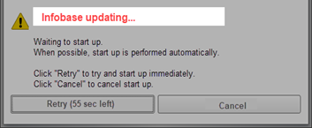
Fig. 398. A message about the lock reason
So, the user can receive a more informative message that explains why they cannot log in to the infobase.
Besides the described method, you can specify the reason why the session cannot be started using the external session management service (the onStartSession method) and session start lock tools.
In some cases, actions executed in the exclusive mode might be terminated. For example, a background job sets the exclusive mode to generate the infobase data export. It is a long-running process. However, the application is developed so that a failed export is retried after a certain period of time. In this case, if you need to perform urgent interactive actions in the infobase, you might need to terminate the export being executed and immediately provide the user with access to the infobase.
To manage the termination of the exclusive access session, use the ExclusiveModeParameters.AllowTerminationAtSessionStart property and the ExclusiveModeTerminationAtSessionStart access right.
To enable the user to close the session that set the exclusive mode, the user must be granted the ExclusiveModeTerminationAtSessionStart right, and the exclusive mode must be set as follows:
ExclusiveModeParameters = New ExclusiveModeParameters;
ExclusiveModeParameters.Message = New FormattedString("Executing ", New FormattedString("data export", , StyleColors.SpecialTextColor), " of
infobase");
ExclusiveModeParameters.AllowTerminationAtSessionStart
= True;
SetExclusiveMode(True, ExclusiveModeParameters);The dialog box about the inability to start the client application will look as follows:
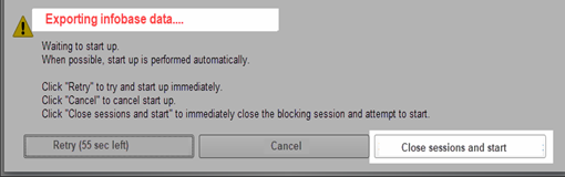
Fig. 399. Close the session and start
A button is added to the dialog box that allows you to close the session and still start an interactive session. This button will be displayed when all the following conditions are met at the same time:
-
A user starting the client application is granted the ExclusiveModeTerminationAtSessionStart access right.
-
When setting the exclusive mode from 1C:Enterprise language, you can close the session. In other words, the ExclusiveModeParameters.AllowTerminationAtSessionStart property is set to True.
-
The infobase which is being attempted to connect to runs in client/server mode or in file mode but access to the infobase is provided via the web server (access over HTTP(s)).
If at least one of the specified conditions is not met, the dialog box does not contain the button to close sessions but a text is displayed as it is specified in the ExclusiveModeParameters.Message parameter.
If a formatted string contains a hyperlink, remember the following behavior features:
-
In a managed application, the system behavior is similar to calling the GotoURL() global context method. The NavigationByURLProcessing() event handler is not called.
-
In an ordinary application, the system behavior is similar to calling the RunApp() global context method.
-
You cannot use internal links to infobase objects in formatted strings. You will not be able to follow such links.
If you need to receive the current parameters of the exclusive mode, use the GetExclusiveModeParameters() global context method. If the method returns Undefined, the exclusive mode is not set in the current infobase or data area.
See also:
-
Client application restart dialog box.
-
Session start lock.
-
External session management service.
-
Access rights.
9.4. Metadata object indexes
9.4.1. General information
Note. Note. Available only for CORP licenses.
When you work with a database, speed of data extraction according to the required criteria is important. With a small number of database records, the system can sequentially iterate through them and compare the values of the required fields for compliance with the required conditions. However, as the number of records increases, constantly iterating through records to select data leads to very slow operation speed.
To solve this issue, there are indexes in the database. Index is a database object created to improve data search performance. An index is created from values of one (regular index) or several (compound index) table columns and pointers to the corresponding table rows. Thus, it allows searching for rows that meet the search criteria. Fields based on which the index is created are called key fields. There are two types of indexes: cluster indexes and non-cluster indexes. If there is a cluster index, table rows are physically ordered by the key value of this index. There can be only one cluster index for each table. A non-cluster index created for a table contains only pointers to table records. Each table can have several non-cluster indexes, each defining its own record order. An index may also include non-key fields. Characteristics of non-key index fields depend on the used DBMS. DBMS indexes can be unique and non-unique. A unique index is an index in which any combination of key field values (a reference to a specific table record) occurs no more than once. A non-unique index allows more than one value for each unique combination of key fields in an index, meaning there can be several records with the same key field values in the database table.
The structure and operation of DBMS indexes is not given in the documentation. To get this information, read the relevant literature and documentation for the used DBMS.
The 1C:Enterprise platform creates a set of indexes (including cluster indexes) for each configuration object. Application developers can have very little influence on these indexes: only specify whether indexing is required for object attributes.
At the same time, the application can use queries that are not suitable for indexes created by the platform. As a result, queries can run a long time and, as a result, reduce overall system performance. To solve this issue, 1C:Enterprise can create additional indexes to some configuration objects: catalogs, documents, information registers, accumulation registers, accounting and calculation registers, business processes, tasks, document journals, sequences, charts of characteristic types, charts of accounts, and exchange plans. Additional indexes are non-cluster, non-unique indexes that can be either regular or compound.
To manage creation of additional indexes in the database, use theUse additional indexes infobase parameter or the SetAdditionalIndexesUsage()/GetAdditionalIndexesUsage() global context methods. Additional indexes are physically created or deleted only during a database configuration update or when the database is forcibly restored to a correct state using verification and repair. During restructuring, operations with additional indexes are performed only when it is necessary to restructure the object for which additional indexes are being created, deleted, or changed. The second condition is a value of the Use additional indexes infobase parameter: when the parameter is enabled, additional indexes are created. When it is disabled, indexes are deleted. During verification and repair (interactively or using Designer batch mode), only the infobase parameter is taken into account. Thus, the physical presence of additional indexes in the infobase is affected by the following operations:
-
Database configuration update (if it is necessary to restructure a configuration object for which additional indexes need to be processed).
-
Verification and repair with Check and enable CORP functionality mode enabled.
-
When running the /IBCheckAndRepair command of Designer batch mode with the -CheckAndEnableCORPFunctionality parameter.
Note that a large number of additional indexes can not only accelerate data retrieval from the infobase, but also slow down data recording. This is because during recording, the current indexes are updated for all tables to which data is recorded. If many indexes are created for the table, updating them will take a long time. Also keep in mind that indexes also take up space on the disk drive. Redundant indexes increase the space occupied by the database. There may be situations when indexes take up more space than indexed data. So, developers need to always keep this in mind and try to maintain a balance between the record speed, the speed of data retrieval from the infobase, and the index size.
9.4.2. Additional index features
Each additional metadata object index has a name, selected fields, and additional fields. The name is used to uniquely identify the additional index by a developer. Selected fields are fields that will be used to build an index. At the physical index level, these will be key fields. Additional fields are fields that will be added to the index being created as non-key fields. If the DBMS does not support non-key fields in the index, additional fields are ignored.
When creating (editing) an additional index, the fields are specified without taking into account how many physical fields will be used to store a particular value. For example, a field of the Number type occupies one physical field, and a union type field occupies three physical fields in a database table. This should be taken into account when creating a compound index. As some of the DBMS supported by the platform do not allow creating indexes that contain more than 16 physical table fields, saving an index is blocked by Designer if adding this index leads to the creation of an index that contains more than 16 physical table fields. The key fields of an index cannot include fields with the ValueStorage type or a string of unlimited length.
An additional index may include fields of the following tables: the main object table, object tables (if any), and virtual tables (for registers only). One index can contain fields of only one of the above types of tables at a time. Virtual table fields can be added to the index for the following reason: a virtual table is usually used in a query with a filter or a join condition. You may often face situations when the fields used in the filter or the join condition generate an optimal index. When selecting a virtual table as a source of additional index fields, 1C:Enterprise automatically creates indexes in all physical tables that generate a virtual table.
If a developer created several additional indexes in Designer to different tables of one object (for example, to the main table and the virtual table), which lead to creation of the same index in the DBMS, the platform physically creates one index in the DBMS. If an additional index to add matches an index that already exists in the database, the platform will create a duplicate index in metadata, but a duplicate index will not be created in the DBMS, since creating a duplicate index makes no sense.
An additional index is created or deleted during the infobase restructuring.
See also:
-
Specifics of storing union type values in a database https://its.1c.ru/db/metod8dev - content:1828:hdoc.
-
Indexing configuration object attributes (see Indexing object attributes).
9.4.3. Additional indexes in 1C:Enterprise language
To enable or disable creation of additional indexes, use the SetAdditionalIndexesUsage()/GetAdditionalIndexesUsage() methods or the dialog box for editing infobase parameters.
You can only configure additional indexes manually using Designer. Using 1C:Enterprise language, you can only get the current list of additional indexes in the application. To access the list of additional indexes, use the AdditionalIndexes property of the metadata object for which this feature is supported. Using this property, you can access the AdditionalIndexes collection, whose elements are AdditionalIndex objects.
Each object that describes an additional index has the following properties: Name (custom index name), IndexedFields (list of key index fields), and AdditionalFields (list of non-key index fields). The IndexedFields and AdditionalFields properties are collections (of the FixedArray type) of values of the IndexField type. The IndexField object contains a description of the indexed field in two properties: Table and Field.
9.4.4. Editing additional indexes
To change a list of additional indexes for a metadata object, right-click the object and then click Additional indexes. As a result, a dialog box for editing additional indexes will be opened.
The form consists of three lists:
-
The list of current indexes (Index) for the selected configuration object (the name of the object is displayed in the dialog box header).
-
In the middle of the form, there is a list of available object fields (Available fields). The list has a hierarchical structure. At the top level, there is a table for which it is planned to create an index, and the fields available for inclusion in the index are subordinate table elements.
-
On the right part of the form (Selected fields), fields of the current index are displayed. The Indexed fields heading contains key index fields, and the Additional fields heading contains non-key index fields.
9.5. Dynamic datasets
1C:Enterprise allows generating dynamic datasets (along with static datasets that are generated using queries to the infobase). The main feature of dynamic datasets (the Select(), SelectHierarchically(), and SelectByRefs() methods), is that they do not read the entire data into memory, but receive it in blocks as they iterate through data using the Next() method. This allows iterating through large amounts of data without having issues with computer memory.
There are two ways to get a dataset:
-
Use the Select() and SelectHierarchically() methods. In this case, the items are selected in accordance with an optional filter by one of the object's attributes. A dataset always reads data that is ordered in some way. To ensure the dynamic dataset works efficiently, the filter and sorting tasks are limited so that one of the indexes can be used when iterating through the dataset. To set the filter value and the ordering option, use the method parameters.
-
Use the SelectByRefs() method. In this case, the list of read objects is determined by a set of references to the read objects (passed in the method parameter). The set generation method is at the discretion of the developer. The dataset reads data in the order in which the list of references is listed in the method parameter. If the references are located in a "complex" object (which consists of several columns), the name of the column that contains the required list of references is also passed to the method.
When iterating through a dynamic dataset, the system reads data in blocks of 25 records (in accordance with the selected order). The read dataset contains all the data of the read objects (catalogs, documents, and so on), including all the tables. Note that the next block is read after all the records of the previously read block are received (using the Next() method). Thus, developers have no control over the relevance of the read information, even if the selection is initiated in a transaction. When you receive a record, it is impossible to distinguish whether it is read at that moment or received from a previously read block.
When you access the dataset properties, the already read data is output. To modify the read object, the GetObject() method will create an object that will be filled with data from the current dataset record. In this case, the object's data will not be read from the database again, as happens if the GetObject() method is called for any reference. Remember the difference in behavior: the Selection.GetObject() method returns an object filled with data from the dataset (previously read), and the Selection.Ref.GetObject() method returns an object filled with data from the database. Getting an object from the dataset will take significantly less time than getting it from the database.
For hierarchical data (catalogs, charts of characteristic types, and charts of accounts), except for the usual selection initiated by the Select() method, there is a hierarchical selection initiated by the SelectHierarchically() method. It differs in that it outputs data by iterating through records by levels. It means that after reading one item, a subordinate item is read if exists. If the subordinate item does not exist, the next item of the same level as the previous dataset item is output. Each reading of subordinate items is implemented as reading a new block.
Note that if the data changes while iterating through the dataset (in the current session or in other sessions), there might be situations such as receiving data of a deleted object, receiving one object twice in the dataset, some records not being included in the dataset, and so on.
This is due to the specifics of dynamic datasets described above. For example, after reading the first block of records, one of the objects was changed, and as a result, the values of the fields by which the dataset is ordered also changed. As a result of this change, the record may be included in the dataset again if it ends up later in the sequence than it was before. If, during the selection in one session, an object was changed in another session and, as a result of this change, ended up earlier in the sequence than it was before, the object might not be included in the dataset at all. For example, while the dataset was iterating through products starting with "A", the "Beta" product was renamed to "Alpha". In this case, it may be not yet included into the dataset part starting with "B", and it will be too late for it to be included into the dataset part starting with "A".
When using dynamic datasets to iterate through and delete hierarchical data, note that when an item is deleted, all its subordinate items are also deleted. Accordingly, when you delete an object while using direct (non-hierarchical) dataset, subordinate objects that are already read in the current block may be deleted. If you try to perform any actions with the objects received from the dataset, an error will occur, since the objects no longer exist in the database. When you use hierarchical datasets, this issue does not arise, since only items subordinate to one parent are included in one block.
Dynamic datasets are recommended, for example, when locking read of multiple records is not required or for scheduled jobs that allow using exclusive mode. In any case, we recommend that you carefully consider changing objects during the iteration through a dynamic dataset, as this may affect the order in which they are included in the dataset.
See also:
- Queries (see Working with queries).
Chapter 10. Data composition system
The data composition system is used to create 1C:Enterprise reports based on their declarative description. Using declarative report description allows you to do the following:
-
Create a report without programming
-
Create various report options
-
Set various versions of user settings
-
Use automatically generated forms for report viewing and customization
-
Split report execution into stages
-
Perform separate stages of report generation on different computers
-
Use individual parts of the data composition system independently
-
Control the report execution process programmatically
-
Set up the report structure
-
Combine multiple tables in a report
-
Create nested reports, and more.
The data composition system features are used:
-
In dynamic lists
-
When preparing data for further processing (for example, in data processors)
10.1. General data composition information
The data composition system is a set of elements, each of which corresponds to a certain stage of report execution. This way, the entire process of report execution in the data composition system is reduced to a sequential transition from one element to another, which eventually results in the final report.
Each element of the data composition system has its own declarative description, the features of programmatic access and serialization to/from XML. Such approach ensures flexible management of various report execution stages.
The main elements of the data composition system are shown in fig. 400.
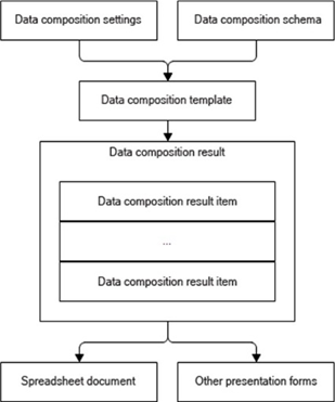
Fig. 400. Main elements of the data composition system
Data composition schema describes the essence of data provided to the report: where to get the data from and how to manage data composition. It is a base which various reports can be generated from. It can contain:
-
Query text with data composition system instructions
-
Description of several data sets
-
Description of available fields
-
Description of links between multiple data sets
-
Description of data retrieval parameters
-
Description of field and grouping templates, and more.
Data composition settings describe everything that a developer or user can customize in an established data composition schema. They can contain:
-
Filter
-
Ordering
-
Conditional appearance
-
Report structure (components of the future report)
-
Data retrieval parameters
-
Data output parameters, and more.
Data composition template is a ready description of how the report must be generated. It combines the composition schema and composition settings. It actually represents the result of applying specific settings to the composition schema and is a ready job for the composition processor to generate a report of the required structure with regard to specific settings.
Data composition result element is a data composition result represented by a set of data composition result elements. As an independent logical entity, data composition result does not exist, only its elements do. Data composition result elements can be output to a spreadsheet document for presentation to the end user or to other types of documents.
The data composition process consists of several stages. They are presented in fig. 401.
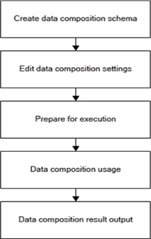
Fig. 401. Stages of data composition process
You can create a data composition schema:
-
Visually using the data composition wizard
-
Visually using any editor that allows editing XML text
-
Programmatically using objects of 1C:Enterprise language
Editing data composition settings. 1C:Enterprise provides a number of 1C:Enterprise language objects and table field extensions to edit composition settings.
Preparing for execution is the process of data composition template generation. This process involves generation of queries required to retrieve data specified in the settings. It also involves generation of report area templates.
Data composition execution is the process of data retrieval, aggregation, and processing.
Data composition result output. Obtained composition result can be output to a document that will be shown to the user. The report can be output in various formats.
The diagram in fig. 402 generally represents the data composition system objects used at various stages of report creation.
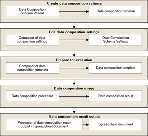
Fig. 402. Data composition system objects
Data composition schema wizard can be used to create a data composition schema.
Data composition settings composer can be used to edit the data composition system settings.
Data composition template composer is used for execution preparation.
Data composition processor performs data composition.
Processor for outputting the data composition result to a spreadsheet document outputs data composition result elements to a spreadsheet document.
A distinctive feature of the report obtained using the data composition system is that it can have a complex structure that includes different combinations of the following elements:
-
Grouping
-
Table
-
Chart
-
Nested report
Therefore, a report obtained using the data composition system is not a table, but a complex hierarchical structure with the elements listed above.
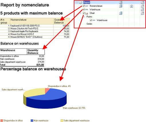
Fig. 403. Report structure
This figure shows an example of a report that contains a chart and grouping by product groups at the first level of the hierarchy. Inside the grouping by product groups, there is a table with turnovers of the products belonging to the specified product group.
10.2. General data composition system objects
10.2.1. "Use" property
Many objects, mainly data composition settings subsystems, have a boolean type Use property. This property allows you to partially disable some functionality without physically removing it. The default value of this property is True, except for specific cases.
10.2.2. Data composition system field
This is an object representing the field data path. The field is implemented as a separate type to eliminate ambiguity in properties of some objects which can take values of both string and field types. It has a constructor with the String parameter that describes the data path. It has no properties or methods. If a data path contains an ID with spaces or special characters, enclose such identifiers in brackets.
10.2.3. Data composition system parameters
The parameter feature was implemented for uniform use and editing of collections of some values whose item composition and type are predefined and cannot be changed. The parameter feature consists of two parts:
-
Available parameters determine the collection composition and allowed types of its elements. The parameter is similar to the data composition system field.
-
Parameter values.
10.3. Data composition schema
The data composition schema is represented by the DataCompositionSchema 1C:Enterprise language object and consists of many other nested objects. The data composition schema has an XML representation. Therefore, it can be created by any tools that can generate XML, as well as used by any tools that can read XML.
The data composition schema is used to provide information about available settings and to create the data composition template during data composition execution (see Data composition template).
The data composition schema wizard is used for visual editing of a data composition schema.
To import the data composition schema from XML, use standard 1C:Enterprise language tools.
XMLReader = New XMLReader;
XMLReader.SetString(Controls.DataCompositionSchemaText.GetText());
DCS
= XDTOSerializer.ReadXML(XMLReader, Type("DataCompositionSchema"));All the expressions described in the data composition schema are written in the expression language of the data composition system (see Data composition system expression language).
10.3.1. Data composition schema components
Each data composition schema contains a set of objects describing a particular section. Consider these components.
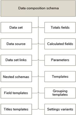
Fig. 404. Data composition schema components
10.3.1.1. Data sources
A data composition schema can include multiple data sources.
A data source is a source to retrieve data from. The 1C:Enterprise infobase serves as a data source.
Data sources are described in the DataSources schema property, which contains a value collection that consists of the DataCompositionSchemaDataSource elements.
10.3.1.2. Data sets
Data sets in the data composition schema contain information about the fields that can be retrieved from this set, data set fields that can be used in filtering, and so on.
Multiple data sets are allowed in the data composition schema (see Using multiple data sets).
Data sets are described in the DataSets schema property. The property contains a value collection that can include the following elements:
-
Query (DataCompositionSchemaDataSetQuery). Data retrieval is described in the query language.
-
Object (DataCompositionSchemaDataSetObject). It describes the name of the external data set from which data will be retrieved.
-
Union (DataCompositionSchemaDataSetUnion). It describes data sets being union components.
All the three data sets contain a number of common properties:
-
Name. Data set name used to access this data set from other data composition schema objects. Data set names must be unique within a single data composition schema.
-
Fields. Description of fields available for the data set.
In addition, the query and object data sets contain the DataSource property, which is the name of the data source from which data will be retrieved. It must contain the name of one data source that is present in the data composition schema (see Data sources).
The query data set contains the Query property, which is the query text used to retrieve data from the data source. You can use a special query language extension in the query text: query language extension for the data composition system (see Query language extension for the data composition system).
The union data set contains the Elements property, which contains a list of data sets included in the union (see Union data set).
10.3.1.2.1. Query data set
It contains an ordinary query to data located in the 1C:Enterprise infobase.
The query data set can contain a batch query. The resulting query will be a batch query. In this case, the composition of the fields that will be placed in the temporary table is automatically determined by the fields used in other queries. If no field is required from the temporary table, it will not be placed in the resulting query. The filter used in the data composition settings is applied to all queries of the batch.
The result of the last query in the batch will be considered the contents of the data set.
Only one data source, including external data sources, can be accessed within one data set.
10.3.1.2.2. Object data set
The object data set is used to output information from a 1C:Enterprise language object to a report: a value table, a query result, current document, and other.
This data "source" is described in the composition schema and filled programmatically. For example, to be passed as an external data set to the composition processor after clicking a button.
10.3.1.2.3. Union data set
The union data set contains the Elements property, which describes data sets to be merged.
Note that field values of the union data set will be retrieved from the fields of nested data sets by their data path. This way, in the example above, the external data set will have the ExpenseAmount field. Data for it will be retrieved from nested data sets whose data path is ExpenseAmount.
10.3.1.2.4. Data set field of the data composition schema
A data set can contain descriptions of fields available to this data set.
Data set fields are described in the Data set fields property, which contains a value collection that consists of the DataCompositionSchemaDataSetField elements.
10.3.1.3. Data set links
Data sets present in a data composition schema can be linked to each other.
Data set links are described in the DataSetLinks property of the data composition schema. The property contains a value collection that consists of the DataCompositionSchemaDataSetLink elements.
10.3.1.4. Calculable fields
In the data composition schema, you can describe fields that will be calculated by some expressions using data set fields. These fields can be used in the settings in the same manner as data set fields, except for the following: calculable field attributes are not supported, hierarchical grouping by calculable fields is not supported.
Calculable fields are described in the DataCompositionSchemaCalculatedFields property of the data composition schema. The property contains a value collection that consists of the DataCompositionSchemaCalculatedField elements.
10.3.1.5. Resource fields
In the data composition schema, you can describe resource fields whose values will be calculated for group records. This is performed by describing the total field.
Total fields are described in the TotalFields property of the data composition schema. The property contains a value collection that consists of the DataCompositionSchemaTotalField elements. When calculating resources, each record of the data set for which the resource is calculated is involved in resource calculation only once.
10.3.1.6. Parameters
The data composition schema contains a description of data parameters.
Data parameters are described in the Data composition schema parameters property. The property contains a value collection that consists of the DataCompositionSchemaParameter elements.
You can specify flags that define whether parameters must be used and whether empty parameters are allowed. For example, using a combination of these flags, you can implement a parameter that prevents report generation if it is unfilled.
10.3.1.7. Nested schemas
The data composition schema can contain descriptions of nested data composition schemas.
Nested data composition schemas are described in the NestedDataCompositionSchemas property of the data composition schema. The property contains a value collection that consists of the NestedDataCompositionSchema elements.
10.3.1.8. Templates
In the data composition schema, you can describe templates that will be used to output a field or grouping. When specifying a template for a field or grouping, the template name described in this property is indicated.
Templates are described in the Data composition schema templates property. The property contains a value collection that consists of the DataCompositionSchemaTemplateDescription elements.
10.3.1.9. Field templates
For each field in the data composition schema, you can specify the template name used to output this field to the composition result.
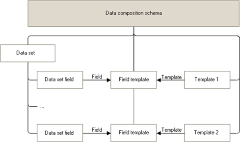
Fig. 405. Field templates
The link between the field and the template is described using the DataCompositionSchemaFieldTemplate object. The collection of these objects is contained in the FieldTemplates property of the DataCompositionSchema object.
10.3.1.10. Grouping templates
For each grouping in the data composition schema, you can specify the template name that will be used to output this grouping.
The link between the grouping and the template is described using the DataCompositionSchemaGroupTemplate object. The collection of these objects is contained in the GroupTemplates property of the DataCompositionSchema object.
10.3.1.11. Grouping header templates
For each grouping, grouping header templates can also be described.
The link between the grouping header and the template is described using the DataCompositionSchemaGroupTemplate object (see previous section). The collection of these objects is contained in the GroupHeaderTemplates property of the DataCompositionSchema object.
10.3.1.12. Default settings
Each report option specified in the data composition schema contains default data composition settings that can be defined by the developer. In this case, the default option will be the one that ranks first in the list of data composition system settings options (Chart by period option in fig. 406). The default settings will be applied if you open a report for the first time and click More actions – Standard settings (All actions – Standard settings). They can also be used to programmatically set default settings.
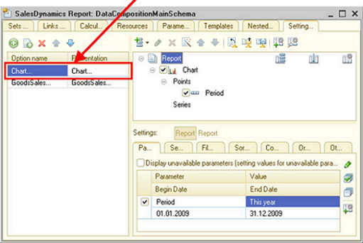
Fig. 406. Default option
10.3.2. Using multiple data sets
The data composition system allows multiple data sets to be used in a single composition.
To use several data sets in one composition, you need to add descriptions of the data sets to be used to the schema and specify the links between the data sets.
Consider the following example.
Write the following data sets: PriceList, Balances, and Sales.
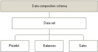
Fig. 407. Example of multiple data sets
Describe the links between data sets. Create a link between the PriceList and Balances data sets and a link between the PriceList and Sales data sets (see fig. 408).

Fig. 408. Data set links
Additionally, describe the resources (see fig. 409).
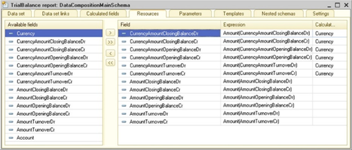
Fig. 409. Data composition schema resources
If the data composition system describes the links between two data sets, the data to which the link is going will be considered dependent. The data set from which the link is going will be considered the parent one in relation to the data set dependent on it.
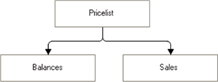
Fig. 410. Dependent data sets
In the examples above, the Balances and Sales data sets will be dependent. The PriceList data set will be the parent one in relation to both of these sets.
There is no indication of the link type in the data composition schema. All the links are considered left external joins. That is, the record of the parent data set will be used in the composition even if no records were found for it in the dependent set.
You can specify the link type in the data composition template (see Data composition template). The link type is generated by the template composer depending on the applied global filters. If a global filter is applied to a dependent data set field, the links generated in the data composition template from this data set to all its parent sets (up to the beginning of the data set hierarchy) will be of the Internal type. This means that parent data set records will be included in the composition only if they are found in the dependent data sets.
For example, if a user applies a global filter on the Warehouse field, the PriceList and Balances data sets will be linked by internal link.
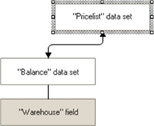
Fig. 411. Internal link
If the data set depends on a certain data set and the link allows using the parameter list, data from the dependent data set will be obtained in batches of 1,000 records. If the parameter list is cannot be used in the link, records will be retrieved one by one.
If both dependent and parent data sets contain a field with the same name, this field will be retrieved from the parent data set. In the examples above, the Products field will always be retrieved from the PriceList data set.
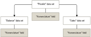
Fig. 412. Common field
Unlinked data sets cannot contain fields with the same name unless they have a common parent that also contains this field. This way, the Balances and Turnovers data sets can contain the Products field, but both of them can not contain the Counterparty field.
The fields from the source data set (parent set) are used in the source expression of the link description. The destination data set (dependent data set) fields are used in the destination link expression. This way, when describing the link between the PriceList and Balances data sets, the Products expression in the SourceExpression property uses the field of the PriceList data set, and the Products expression in the DestinationExpression property uses the field of the Balances data set.
Fields from unlinked data sets cannot be used in the same grouping. At the same time, data sets that have common parent data sets are not considered to be linked. An exception is made for total fields that can be used in any grouping. In the example above, we cannot use the Warehouse and Counterparty fields in the same grouping. However, we can use the BalanceCount and TurnoverAmount fields, since these are resources.
Dependent data set data cannot be retrieved without retrieving parent data set data. That is, upon data retrieval from a dependent set, data from the parent set (and all the parents of the parent) will also be automatically retrieved. In our example, when retrieving the Balances data set, data from the PriceList data set will be retrieved as well.
If a grouping uses data sets from multiple data sets, the last dependent data set will be iterated during composition execution. So, if the grouping uses the fields from the PriceList and Balances data sets, iteration will be performed by the Balances set.
If no fields from the linked data set are enabled in the settings, the data set will not be included in the data composition template.
10.3.3. Query language extension for the data composition system
The query language extension for the data composition system is implemented using special syntax instructions enclosed in braces and placed directly in the query text.
10.3.3.1. Syntax elements of the query language extension of the data composition system
SELECT
Description:
This expression describes the fields that the user can select for output. After this keyword, comma-separated customizable aliases of the fields from the main query selection list are specified.After the field alias, there can be a combination of characters ".*", which means that child fields from this field can be used.
For example, the Products.* record means that child fields of the Products field (for example, the Products.Code field) can be used. The SELECT item can be present in the first query of the union only.
Example:
{SELECT
Product, Warehouse}WHERE
Description:
Describes the fields that can be filtered by the user. This expression uses table fields. Using aliases of the selection list fields is not allowed. Each union part can contain its own WHERE item.If parameter values are not specified, the WHERE expression is not included in the resulting query.
Example:
{WHERE Products.*, Warehouse }
{WHERE
Document.Date >= &StartDate, Document.Date <= &EndDate}CHARACTERISTICS
Description:
To ensure operations with characteristics, the syntax for describing characteristics has been introduced in the query language extension for the data composition system.The example below describes characteristics for the fields of the Reference type to the Products catalog.
The characteristics describe the following properties:
-
TYPE. Name of the type for which the characteristics are described.
-
CHARACTERISTICTYPES. Table name or a query for getting a list of characteristics. You can use the ALLOWED keyword in the query. In this case, the list of characteristics will contain only those characteristics that are allowed for the user by the imposed data access restrictions.
If the list of characteristics is specified not by a query, but by a table name, the ALLOWED keyword is also used in the query for obtaining the list of characteristics generated by 1C:Enterprise.
-
KEYFIELD. Name of the field containing the characteristic ID.
-
NAMEFIELD. Name of the field containing the characteristic name.
-
VALUETYPEFIELD. Name of the field containing the value type of the characteristic. If the value type is not specified, it is considered that the characteristic is of the Boolean type.
-
CHARACTERISTICVALUES. Table name or a query to retrieve characteristic values.
-
OBJECTFIELD. Name of the field containing the object ID (for example, a product reference).
-
TYPEFIELD. Name of the field containing the characteristic ID.
-
VALUEFIELD. Name of the field containing the characteristic value. If not specified, the value will be True (if the object has such characteristic). Otherwise, False.
Example:
{CHARACTERISTICS TYPE(Catalog.Products)
CHARACTERISTICTYPES (SELECT
AddlPropertiesTypes.Ref, AddlPropertiesTypes.Description, AddlPropertiesTypes.ValueType
FROM
ChartOfCharacteristicTypes.AddlPropertiesTypes
AS AddlPropertiesTypes)
KEYFIELD Ref
NAMEFIELD Description
VALUETYPEFIELD ValueType
CHARACTERISTICVALUES
InformationRegister.AddlProperties
OBJECTFIELD Products
TYPEFIELD PropertyType
VALUEFIELD Property
}Parameters
Description:
In addition to the basic elements, the data composition system accepts elements recorded in the parameters of virtual tables. In such cases, the type of fields depends on the type of parameter where the elements are located.The StartDate, EndDate, Products, and Warehouse fields (see the example) will become available for filtering, which means that the user will be able to apply filters to them.
Example:
SELECT
ProductAccountingTurnover.Products
AS Products, ProductAccountingTurnover.Warehouse
AS Warehouse, ProductAccountingTurnover.ReceiptCount
AS ReceiptCount, ProductAccountingTurnover.SalesCount
AS SalesCount
FROM
AccumulationRegister.ProductAccounting.Turnover({&StartDate}, {&EndDate}, , {Products.*, Warehouse.*}) AS ProductAccountingTurnover10.3.3.2. Automatic population of available fields
When query fields are automatically filled, the following actions are performed:
-
All the fields in the selection list and their child fields become available for selection, ordering, grouping, filtering, and so on.
-
Parameters of virtual tables become available for filtering.
10.3.4. Data composition system expression language
The expression language of the data composition system is used to record expressions applied in various subsystems. Expressions are used in the following subsystems:
-
Data composition system: to describe calculated fields, total fields, link expressions, and so on.
-
Data composition settings: to describe user field expressions.
-
Data composition template: to describe data set link expressions, template parameters, and so on.
Note. Note. In the data composition expression language, you cannot get a field separated by dot from the expression.
Note. Important. The data composition system expression is calculated in safe mode (see Safe mode).
10.3.4.1. Literals
The expression can contain literals of the types described below.
String
Description:
Enclose string literals in double quotation marks (").If you need to include a double quotation mark (") in a string literal, use two double quotation marks.
Example:
"Literal ""with a quoted
text"""Number
Description:
Write numbers without spaces, in decimal format. Use the period (.) as a decimal separator.Example:
10.5
200Date
Description:
For Date literals, use the DATETIME key literal. After the keyword, specify the year, month, day, hours, minutes, and seconds in parentheses, separated by commas. Specifying the time part is optional.Example:
// January 6, 1975
DATETIME(1975, 1, 06)
// December 2, 2006, 23 hours 56 minutes 57 seconds
DATETIME(2006, 12, 2, 23, 56, 57)Boolean
Description:
For Boolean values, use True and False literals.Value
Description:
For literals of other types (system enumerations or predefined data), use the Value keyword followed by the literal name in parentheses.Example:
Value(AccountType.Active)Fields
Description:
Expressions can include fields of data sets. A field is identified by data path. Data path parts are dot-separated (".)" Field names are case-insensitive. If a data path contains an ID with spaces or special characters, enclose such identifiers in brackets.Example:
Product.SKU
Sales.AmountTurnover
Sales.[Amount turnover]Parameters
Description:
Expressions can include parameters. To include a parameter in an expression, precede the parameter name with an ampersand "&".Example:
&Counterparty
&StartDateType
Description:
Generates values of the Type type. Use the Type keyword to define a type.Example:
Type("String")10.3.4.2. Operations with numbers
Unary "-"
Description:
This operation negates a number.Example:
Sales.CountUnary "+"
Description:
This operation does not change a number.Example:
+Sales.CountBinary "-"
Description:
This operation calculates the difference between two numbers.Example:
BalanceAndTurnover.OpeningBalance - BalanceAndTurnover.ClosingBalance
BalanceAndTurnover.OpeningBalance - 100
400 - 357Binary "+"
Description:
This operation calculates the sum of two numbers.Example:
BalanceAndTurnover.OpeningBalance + BalanceAndTurnover.Turnover
BalanceAndTurnover.OpeningBalance + 100
400 + 357Multiplication "*"
Description:
This operation calculates the product of two numbers.Example:
Products.Price * 1.2
2 * 3.14Division "/"
Description:
This operation calculates the quotient of two numbers.Example:
Products.Price / 1.2
2 / 3.14Remainder "%"
Description:
This operation calculates the remainder in division of two numbers.Example:
Products.Price % 1.2
2 % 3.1410.3.4.3. Operations with strings
Concatenation (Binary "+")
Description:
This operation concatenates two strings.Example:
Product.SKU + ": "+ Product.DescriptionLIKE
Description:
This operation checks whether a string matches the specified template. The check is case-insensitive for string characters for any used DBMS. The value of the LIKE operator is True if the expressionvalue matches the template, andFalse otherwise.The following characters in a template line have a specific meaning different from an ordinary string character:
-
The percent character (%) stands for any number (including zero) of any characters.
-
The underscore (_) stands for any single character.
-
One or more characters in brackets ([...]) stand for one character from the ones specified there. An enumeration can contain ranges, such as a-z, meaning any character within the range, including the range limits.
-
A negation sign followed by one or more characters in brackets ([^...]) stands for any character except for those listed after the negation sign.
Any other character represents itself only and does not have any additional meaning. If you want the system to recognize one of the listed characters as regular ones, specify the ESCAPE keyword before it.
For example, the following template stands for a substring including the following sequence of characters:
-
Letters A or a
-
Any character
-
One digit
-
One of the characters [, ] or ^
-
Underscore character
-
Letters E or e
This sequence can begin anywhere in the string.
Example:
"%A_[0-9][/[/]/ ]/_e%"
ESCAPE "/"10.3.4.4. Comparison operations
Equal (=)
Description:
This operation compares two operands for equality.Example:
Sales.Counterparty = Sales.ProductMainSupplierNot equal (<>)
Description:
This operation checks whether the first operand is not equal to the second operand.Example:
Sales.Counterparty <> Sales.ProductMainSupplierLess than (<)
Description:
This operation checks whether the first operand is less than the second operand.Example:
CurrentSales.Amount < PreviousSales.AmountGreater than (>)
Description:
This operation checks whether the first operand is greater than the second operand.Example:
CurrentSales.Amount > PreviousSales.AmountLess than or equal to (<=)
Description:
This operation checks whether the first operand is less than or equal to the second operand.Example:
CurrentSales.Amount <= PreviousSales.AmountGreater than or equal to (>=)
Description:
This operation checks whether the first operand is greater than or equal to the second operand.Example:
CurrentSales.Amount >= PreviousSales.AmountThe string begins with a substring (BeginsWith)
Description:
This operation checks that the value being checked starts with the string specified in the condition. The condition can be specified by an actual value and a template. The following characters in a template line have a specific meaning different from an ordinary string character:-
The slash mark (/) means that the following character is a regular character.
-
The percent character (%) stands for any number (including zero) of any characters.
-
The underscore (_) stands for any single character.
The string does not start with a substring (NotBeginsWith)
Description:
This operation checks that the value being checked does not start with the string specified in the condition. The condition can be specified by an actual value and a template. The following characters in a template line have a specific meaning different from an ordinary string character:-
The slash mark (/) means that the following character is a regular character.
-
The percent character (%) stands for any number (including zero) of any characters.
-
The underscore (_) stands for any single character.
The string matches the template (Like)
Description:
This operation checks that the value being checked matches the specified template. The following characters in a template line have a specific meaning different from an ordinary string character:-
The slash mark (/) means that the following character is a regular character.
-
The percent character (%) stands for any number (including zero) of any characters.
-
The underscore (_) stands for any single character.
The string does not match the template (NotLike)
Description:
This operation checks that the value being checked does not match the specified template. The following characters in a template line have a specific meaning different from an ordinary string character:-
The slash mark (/) means that the following character is a regular character.
-
The percent character (%) stands for any number (including zero) of any characters.
-
The underscore (_) stands for any single character.
Check of value presence in a list (IN)
Description:
This operation checks whether a value is present in the passed list of values. The operation result is True if the value is found, or False otherwise.Example:
Product IN (&Product1, &Product2)Check of value presence in a data set (IN)
Description:
This operation checks whether a value is present in the specified data set. The data set must contain a single field.Example:
Sales.Counterparty IN CounterpartiesNULL value check operation (IS NULL)
Description:
This operation returns True if the specified value is NULL.Example:
Sales.Counterparty IS NULLValue check for NULL inequality (IS Not NULL)
Description:
This operation returns True if the specified value is not NULL.Example:
Sales.Counterparty IS Not NULL10.3.4.5. Logical operations
Logical expressions use Boolean type values as operands.
Not operation
Description:
The Not operation returns True if its operand is False and False if its operand is True.Example:
Not Document.Consignee = Document.ShipperAnd operation
Description:
The And operation returns True if both operands are True and False if one of the operands is False.Example:
Document.Consignee = Document.Shipper AND
Document.Consignee = &CounterpartyOr operation
Description:
The Or operation returns True if one of the operands is True and False if both operands are False.Example:
Document.Consignee = Document.Shipper Or
Document.Consignee = &Counterparty10.3.4.6. Aggregate functions
Aggregate functions perform certain actions on data sets.
SUM
Syntax:
Sum(Expression)Description:
TheSum aggregate function calculates the sum of values for expressions passed to it as an argument, for all the detailed records. An Array can be passed as a parameter. In this case, the function will be applied to the array contents.Example:
SUM(Sales.AmountTurnover)COUNT
Syntax:
Count(Expression)Description:
The Count function calculates the number of values that are different from NULL. An Array can be passed as a parameter. In this case, the function will be applied to the array contents.Example:
COUNT(Sales.Counterparty)COUNT (DISTINCT)
Syntax:
Count(Distinct Expression)Description:
This function calculates the number of distinct values. To get distinct values, specify Distinct before the Count method parameter. An Array can be passed as a parameter. In this case, the function will be applied to the array contents.Example:
COUNT(Distinct Sales.Counterparty)MAX
Syntax:
Max(Expression)Description:
This function gets the maximum value. An Array can be passed as a parameter. In this case, the function will be applied to the array contents.Example:
MAX(Balances.Count)MIN
Syntax:
Min(Expression)Description:
This function gets the minimum value. An Array can be passed as a parameter. In this case, the function will be applied to the array contents.Example:
MIN(Balances.Count)AVG
Syntax:
Avg(Expression)Description:
This function gets the average value for values other than NULL. An Array can be passed as a parameter. In this case, the function will be applied to the array contents.Example:
AVG(Balances.Count)ARRAY
Syntax:
Array([Distinct] Expression)Description:
The function generates an array of expression values for each detailed record.You can use a value table as a parameter. In this case, the function returns an array of values from the first column of the value table passed as a parameter.
If an expression contains the Array function, it is considered an aggregate expression.
If the Distinct keyword is specified, the resulting array will not contain duplicate values.
Example:
ReportsFunctions.StdDeviation(Array(Sum))VALUETABLE
Syntax:
ValueTable([Distinct] Expression1 [AS ColumnName1][, Expression2 [AS ColumnName2], ...])Description:
This function generates a value table that contains the number of columns that matches the number of function parameters. Detailed records are retrieved from the data sets required to calculate all the expressions specified in the function parameters.If the function parameters are balance fields, the resulting value table contains the values from the records retrieved by unique combinations of dimensions from other periods. At the same time, the values are only retrieved for balance fields, dimensions, accounts, period fields, and their attributes. Values of the other fields in records from other periods are considered to be NULL.
If an expression contains the ValueTable function, it is considered an aggregate expression.
If the Distinct keyword is specified, the resulting value table will not contain rows with the same data.
For each column, you can specify a name using the AS keyword following the expression that generates the column value.
Example:
ReportsFunctions.ValueTableToString(ValueTable(Warehouse
AS Warehouse, CountBalance AS Balance))GROUPBY
Syntax:
GroupBy(<Expression>, <ColumnsNumbers>)Description:
This function deletes duplicates from an array.Parameters:
<Expression>
Array or ValueTable. Duplicates are removed for the value in this formal parameter.
<ColumnsNumbers>
String. It is used if the Expression parameter is of the ValueTable type. Value table column numbers or names (comma-separated) to search for duplicates. By default, the search is performed in all columns.
Example:
GroupBy(ValueTable(PhoneNumber, Address)
,"PhoneNumber");GETPART
Syntax:
GETPART(<Expression>, <ColumnsNumber>)Description:
The function retrieves a value table that contains specified columns of the source value table.Parameters:
<Expression>
ValueTable. Value table to retrieve the columns from.
<ColumnsNumbers>
String. Value table column names or numbers (comma-separated) to be retrieved.
Return value:
Value table with only those columns that are specified in the ColumnsNumbers parameter.
Example:
GetPart(GroupBy(ValueTable(PhoneNumber, Address), "PhoneNumber"),"PhoneNumber");ORDER
Syntax:
Order(<Expression>, <ColumnsNumbers>)Description:
Orders array and value table elements.Parameters:
<Expression>
Array or ValueTable. Object to be ordered.
<ColumnsNumbers>
It is used if the Expression parameter is of the ValueTable type. Value table column names or numbers (comma-separated) to be ordered. By default, the search is performed in all columns.
You can specify the ordering direction or the automatic ordering flag after each column.
Return value:
An array or value table that are ordered according to the passed parameters.
Example:
Order(ValueTable(PhoneNumber, Address, CallDate),"CallDate Desc");JOINSTRINGS
Syntax:
JOINSTRINGS(<Values>, <ElementsSeparator>, <ColumnsSeparator>)Description:
Joins multiple strings into a single string.Parameters:
<Values>
Values whose string presentations must be joined into a single string. If the parameter value type is Array, array elements are joined into a string. If the parameter value type is ValueTable, all the table columns and rows are joined into a string.
<ElementsSeparator>
String. It contains the text to be used as a separator between array elements and value table rows. The default value is the line feed character.
<ColumnsSeparator>
String. It contains the text to be used as a separator between value table columns. "; " by default.
Return value:
Joined string.
Example:
JoinStrings(ValueTable(PhoneNumber, Address));GROUPPROCESSING
Syntax:
GroupProcessing(<Expressions>, <HierarchyExpressions>, <GroupingName>)Description:
A value table is generated to contain the parameter values (in columns) for each group record (in rows). If the grouping is hierarchical, each hierarchy level is processed separately. Hierarchical record values are also placed in the data table. This value table will be placed in the Data property of the returned object.A row of the passed value table for which the function is currently being evaluated is placed to the CurrentItem property.
When implementing a function that can take group processing data as a parameter, consider that the NULL value can be passed to the function. For example, this may occur if the GroupProcessing() function is evaluated with the name of the grouping that is currently not available.
Parameters:
<Expressions>
A string with comma-separated expressions to be evaluated. Each expression can be followed by an optional AS keyword and a column name in the resulting value table. Each expression describes a column of the generated value table.
<HierarchyExpressions>
Expressions to be calculated for hierarchical records. It is similar to the Expressions parameter, but HierarchyExpressions is used for hierarchical records, while Expressions is used for non-hierarchical records. If this parameter is not specified, expressions specified in the Expression parameter are used to calculate hierarchical record values.
<GroupingName>
The name of the grouping for group processing calculation. If this parameter is not specified, the calculation is performed in the current grouping. If the calculation is performed in a table and the parameter is a blank string or is not specified, the value is calculated for the row grouping. The template composer replaces this name with the grouping name in a generated data composition template. If the grouping is unavailable, the function is replaced with NULL.
Return value:
DataCompositionGroupProcessingData object.
Example:
An implementation example of the ABCClassification() function, which returns 1 if the value is 75% of the total amount, 2 if the percentage is between 75% and 95%, and 3 in other cases.// Evaluate ABC classification.
Function ABCClassification(Data) Export
Var ValueTable;
If Data = Null Then
Return Null;
EndIf;
If TypeOf(Data) <> Type("DataCompositionGroupProcessingData") Then
Message(TypeOf(Data));
Raise
"Only an object of the DataCompositionGroupProcessingData type can be
passed to the ABCClassification() function";
EndIf;
If Not
Data.ProcessingTempData.Property("ABCClassificationValueTable", ValueTable) Then
// evaluate
the classification once at the first run
// and then
store the performed calculation and will
// use it
ValueTable = Data.Data.Copy();
ValueTable.Columns.Add
("Number", New TypeDescription ("Number"));
Number = 0;
TotalSum = 0;
For Each
ValueTableRow In ValueTable Do
ValueTableRow.Number
= Number;
Number = Number + 1;
If ValueTableRow[0] <> NULL Then
TotalSum = TotalSum + ValueTableRow[0];
EndIf;
EndDo;
ValueTable.Sort(ValueTable.Columns[0].Name
+ "Desc");
ValueTable.Indexes.Add("Number");
AccumulatedSum
= 0;
ClassAIndex = Undefined;
ClassBIndex = Undefined;
For Each
ValueTableRow In ValueTable Do
If ValueTableRow[0] <> NULL Then
AccumulatedSum
= AccumulatedSum + ValueTableRow[0];
EndIf;
If TotalSum
= 0 Then
Percentage
= 1;
Else
Percentage
= AccumulatedSum / TotalSum;
EndIf;
If Percentage > 0.75 Then
If ClassAIndex = Undefined Then
ClassAIndex
= ValueTable.Index(ValueTableRow);
ElsIf Percentage > 0.90 Then
If ClassBIndex = Undefined Then
ClassBIndex
= ValueTable.Index(ValueTableRow);
EndIf;
Break;
EndIf;
EndIf;
EndDo;
Data.ProcessingTempData.Insert("ABCClassificationValueTable", ValueTable);
Data.ProcessingTempData.Insert("ABCClassificationClassAIndex", ClassAIndex);
Data.ProcessingTempData.Insert("ABCClassificationClassBIndex", ClassBIndex);
EndIf;
If Data.CurrentItem = Undefined Then
// Totals by
grouping. Return Null;
Else
String = ValueTable.Find(Data.Data.Index(Data.CurrentItem), "Number");
If String = Undefined Then
Return Null;
Else
Index = ValueTable.Index(String);
If Index
<= Data.ProcessingTempData.ABCClassificationClassAIndex Then
Return 1;
ElsIf Index
<= Data.ProcessingTempData.ABCClassificationClassBIndex Then
Return 2;
Else
Return 3;
EndIf;
EndIf;
EndIf;
EndFunctionTo get a class, you can use the following expression in a composition expression (for example, in a resource or a custom field):
ABCClassification(GroupProcessing("Sum(TurnoverSum)"))EVERY
Syntax:
Every(<X>)Description:
TheEvery aggregate function determines the presence of at least one False value in a passed set.Return value:
True if the passed set does not contain any False values.
False if the passed set contains at least one False value.
ANY
Syntax:
Any(<X>)Description:
The Any aggregate function determines the presence of at least one True value in a passed set.Return value:
True if the passed set contains at least one True value.
False if the passed set does not contain any True values.
STDDEV_POP
Syntax:
STDDEV_POP(<X>)Description:
Calculates the standard population variance for the passed set.It is calculated as: SQRT(Var_Pop(X)).
Return value:
Function calculation result.
STDDEV_SAMP
Syntax:
STDDEV_SAMP(<X>)Description:
Calculates the standard sample deviation for the passed set.It is calculated as: SQRT(Var_Samp(X)).
Return value:
Function calculation result.
VAR_SAMP
Syntax:
VAR_SAMP(<X>)Description:
Calculates sample variance for the passed set.It is calculated as:(SUM(X2)-SUM(X)2/COUNT(X))/(COUNT(X)-1). If the number of records in a set is 1 (COUNT(X)=1), the return value is NULL.
Return value:
Function calculation result.
VAR_POP
Syntax:
VAR_POP(<X>)Description:
Calculates population variance for the passed set. NULL values are ignored.It is calculated as:(SUM(X2)-SUM(X)2/COUNT(X))/(COUNT(X)).
Return value:
Function calculation result.
COVAR_POP
Syntax:
COVAR_POP(, )Description:
Calculates the covariance of a set of pairs for passed sets.It is calculated as:(SUM(YX)-SUM(X)SUM(Y)/N)/N.N is the number of X and Y value pairs from the passed sets, where neither X, nor Y values are NULL. Pairs with at least one NULL value are ignored.
Return value:
Function calculation result.
COVAR_SAMP
Syntax:
COVAR_SAMP(<Y>, <X>)Description:
Calculates the covariance sample of a set of pairs for passed sets.It is calculated as:(SUM(YX)-SUM(Y)SUM(X)/N)/(N-1). N is the number of X and Y value pairs from the passed sets, where neither X, nor Y values are NULL. Pairs with at least one NULL value are ignored.
Return value:
Function calculation result or NULL if the function is applied to empty sets.
CORR
Syntax:
CORR(<Y>, <X>)Description:
Calculates the correlation factor of a set of pairs for passed sets. It is calculated as:Covar_Pop(Y, X)/(Stddev_Pop(Y)* Stddev_Pop(X)). Pairs with at least one NULL value are ignored.Return value:
Function calculation result or NULL if the function is applied to empty sets.
REGR_SLOPE
Syntax:
REGR_SLOPE(<Y>, <X>)Description:
Calculates the slope of the regression line.It is calculated as:Covar_Pop(Y, X)/Var_Pop(X). Pairs with at least one NULL value are ignored.
Return value:
Function calculation result.
REGR_INTERCEPT
Syntax:
REGR_INTERCEPT(<Y>, <X>)Description:
Calculates the Y-intercept of the regression line.It is calculated as: Mean(Y)-Regr_Slope(Y, X)*Mean(X). Pairs with at least one NULL value are ignored.
Return value:
Function calculation result.
REGR_COUNT
Syntax:
REGR_COUNT(<Y>, <X>)Description:
This function calculates the number of non-NULL number pairs.Return value:
Function calculation result.
REGR_R2
Syntax:
REGR_R2(<Y>, <X>)Description:
Calculates the determination factor for the regression. Pairs with at least one NULL value are ignored.Return value:
-
NULL if VAR_POP(X) is0.
-
1 if VAR_POP(Y) is0 and VAR_POP(X) is not 0.
-
Pow(CORR(Y, X), 2) if VAR_POP(Y) is more than 0 and VAR_POP(X) is not 0.
REGR_AVGX
Syntax:
REGR_AVGX(<Y>, <X>)Description:
Calculates the average of the independent <X> variables for the regression line, after eliminating the pairs with at least one NULL value.It is calculated as:Mean(X).
Return value:
Function calculation result.
REGR_AVGY
Syntax:
REGR_AVGY(<Y>, <X>)Description:
Calculates the average of the dependent <Y> variables for the regression line, after eliminating the pairs with at least one NULL value.It is calculated as: Mean(Y).
Return value:
Function calculation result.
REGR_SXX
Syntax:
REGR_SXX(<Y>, <X>)Description:
Performs calculation as per formula:REGR_COUNT(Y, X) * VAR_POP(X). Pairs with at least one NULL value are ignored.
Return value:
Function calculation result.
REGR_SYY
Syntax:
REGR_SYY(<Y>, <X>)Description:
Performs calculation as per formula:REGR_COUNT(Y, X) * VAR_POP(Y). Pairs with at least one NULL value are ignored.
Return value:
Function calculation result.
REGR_SXY
Syntax:
REGR_SXY(<Y>, <X>)Description:
Performs calculation as per formula:REGR_COUNT(Y, X) * COVAR_POP(Y, X). Pairs with at least one NULL value are ignored.
Return value:
Function calculation result.
RANK
Syntax:
RANK(<Order>, <HierarchyOrder>, <GroupName>)Description:
The function calculates the place of the current record among the records of the current grouping if it is ordered according to the function parameters. Numbering starts with 1.Parameters:
String. Contains comma-separated expressions for ordering group records. You can set the ordering direction by specifying Asc or Desc. You can also specify the AutoOrder string after the field. In this case, ordering fields defined for the referred object are used for ordering references. If the sequence is not specified, the value is calculated based on the grouping sequence.<HierarchyOrder>
String. String with expressions for ordering hierarchical records.
<GroupingName>
String. The name of the grouping where the function is calculated. If this parameter is not specified, the calculation is performed in the current grouping. If the calculation is performed in a table and the parameter is a blank string or is not specified, the value is calculated for the row grouping. The template composer replaces this name with the grouping name in a generated data composition template. If the grouping is unavailable, the function is replaced with NULL.
Return value:
Serial number. If a sequence includes multiple records with identical order field values, the function returns identical values for these records.
CLASSIFICATIONABC
Syntax:
ClassificationABC(<Value>, <GroupCount>, <PercentageForGroups,> <GroupingName>)Description:
Performs an ABC classification of each record in the specified grouping.Parameters:
String. Specifies an expression for calculating the classification.<GroupCount>
Number. Specifies how many groups the value set must be broken into.
<PercentageForGroups>
String. The volume (in %) of each splitting group, except for the last group. Listed in a string, separated by commas.
<GroupingName>
String. The name of the grouping where the function is calculated. If this parameter is not specified, the calculation is performed in the current grouping. If the calculation is performed in a table and the parameter is a blank string or is not specified, the value is calculated for the row grouping. The template composer replaces this name with the grouping name in a generated data composition template. If the grouping is unavailable, the function is replaced with NULL.
Return value:
Class number. 1 stands for class A, 2 stands for class B, 3 stands for class C, and so on.
Example:
ClassificationABC("AmountTurnover, 3, "15, 25")10.3.4.7. Other operations
CASE operation
Description:
The CASE operation selects one of several values based on the specified conditions.Example:
CASE When Amount > 1000 Then Amount Else 0 End10.3.4.8. Rules for comparing two values
If types of compared values are not identical, the relationship between the values is defined based on the type priority:
-
NULL (the lowest priority)
-
Boolean
-
Number
-
Date
-
String
-
Reference types
-
Other types
The relationship between different reference types is defined based on table reference numbers corresponding to one type or another. The relations between other types are defined by comparing IDs of these types.
If data types are identical, their values are compared according to the following rules:
-
For the Boolean type, True is greater than False.
-
For the Number type, common number comparison rules are applied.
-
For the Date type, earlier dates are less than later dates.
-
For the String type, string comparison is based on regional database settings.
-
Reference types are compared by their values (for example, record numbers, and so on).
-
The result of array comparison is based on the consecutive comparison of array elements.
-
The result of table comparison is based on the consecutive comparison of value table cells.
-
When comparing values not described above, the following rules are applied:
-
In case of ordering, string presentations of objects are compared.
-
When comparing in expressions, in = and <> operators, the algorithm output is the result of the check whether an object is being compared to itself.
-
The comparison operations <, <=, >, >= do not support exceptions.
-
10.3.4.9. Operations with NULL value
Any operation where one of the operands is NULL value returns NULL.
The exceptions are:
-
The And operation returns NULL only if none of the operands is False.
-
The Or operation returns NULL only if none of the operands is True.
10.3.4.10. Operation priorities
Operations have the following priorities (the first operation in the list has the lowest priority):
-
Or
-
And
-
Not
-
IN, IS NULL, IS Not NULL
-
=, <>, <=, <, >=, >
-
Binary +, Binary –
-
*, /, %;
-
Unary +, Unary –
10.3.4.11. Functions
10.3.4.11.1. Algebraic functions
You can use these functions to perform various algebraic functions:
| Function | Description |
|---|---|
| EXP(<X>) | Calculates the value of the e constant raised to a given power. |
| LOG(<X>) | Calculates the natural logarithm of the ln() number. |
| LOG10(<X>) | Calculates the natural logarithm of the lg() number. |
| POW(<X>, <Y>) | Raises X to the Y power. |
| SQRT(<X>) | Calculates the square root of a number. |
10.3.4.11.2. UPPER
Syntax:
Upper(<String>)Description:
Converts all characters of a parameter string to uppercase.Parameters:
- String. String to be converted to uppercase.Return value:
String.
10.3.4.11.3. CAST
Description:
This function extracts a type from an expression that can contain a union type. If the expression contains a type other than the required one, it returns NULL.Parameters:
- Converted expression.- Type. String that contains a type string. For example, Number, String, and so on. In addition to primitive types, the string can also contain a table name. In this case, the function attempts to cast to a reference to that table.
Example:
CAST(Data.Attribute1, "Number(10,3)")10.3.4.11.4. EVAL
Syntax:
Eval(<Expression>, <Grouping>, <CalculationType>)Description:
The EVAL function calculates an expression within a certain grouping context.The function is used for compatibility with previous 1C:Enterprise versions. We recommend that you use the EvalExpression function instead.
Parameters:
<Expression>
A string containing an expression to be calculated.
<Grouping>
A string that contains a name of a grouping where an expression is calculated. If the grouping name is a blank string, the calculation is performed in the context of the current grouping. If the parameter value is Overall, the calculation is performed in the context of the grand total. In other cases, the calculation is performed in the context of the parent grouping with this name.
<CalculationType>
A string that contains the calculation type. If the parameter value is Overall, the expression is calculated for all the records of the grouping. If the parameter value is Grouping, the values are calculated for the current group record of the grouping.
Example:
Sum(Sales.AmountTurnover)/EVAL("Sum(Sales.AmountTurnover)", "Overall")In this example, the result is the ratio of the sum of the grouping record by the Sales.AmountTurnover field to the sum of all composition records by this field.
10.3.4.11.5. EVALEXPRESSION
Syntax:
EvalExpression(<Expression>, <Grouping>, <EvalArea>, <Start>, <End>, <Sorting>, <HierarchicalSorting>, <IdenticalOrderValuesProcessing>)Description:
This function calculates an expression within a certain grouping context. When the interval is specified, the calculation is possible only for aggregate functions of the data composition system (see Aggregate functions). Calculation is not performed for the other functions.The function is calculated based on grouping filters, but not hierarchical filters. The function cannot be applied to a grouping in a group filter of that grouping. For example, you cannot use EvalExpression("Sum(AmountTurnover)", , "Overall") > 1000 in the Products grouping filter. However, you can use it in a hierarchical filter. If the last record precedes the first one, it is considered that there are no records for calculating detailed data and aggregate functions.
When interval expressions are calculated for the grand total (the Grouping parameter has the Overall value), it is considered that there are no records for calculating detailed data and aggregate functions.
If the ordering expression contains fields that cannot be used in the grouping, the template composer replaces the EvalExpression function with NULL when generating the EvalExpression function expression.
Parameters:
<Expression>
String. Expression to be calculated.
<Grouping>
String. Contains the name of the grouping where the expression is calculated. If a blank string is used as a grouping name, the calculation is performed within the current grouping context. If the parameter value is Overall, the calculation is performed in the context of the grand total. In other cases, the calculation is performed in the context of the parent grouping with this name.
Example:
Sum(Sales.AmountTurnover) / Eval("Sum(Sales.AmountTurnover)", "Overall")In this example, the result is the ratio of the sum of the grouping record by the Sales.AmountTurnover field to the sum of all composition records by this field.
<EvalArea>
String. The parameter can take values:
-
Overall. The expression will be calculated for all the grouping records.
-
Hierarchy. The expression will be calculated for the parent hierarchical record, if any, or for the entire grouping if there is no parent hierarchical record.
-
Grouping. The expression will be calculated for the current group record of the grouping.
-
NotResourceGroup. When calculating the function for group record by resources, the expression will be calculated for the first group record of the original grouping.
When calculating the EvalExpression() function with the NotResourceGroup value for group records that are not groupings by resources, the function is calculated in the same way as if the parameter value were Grouping.
When the data composition template composer generates a data composition template, it outputs an expression calculated using the EvalExpression() function with the NotResourceGroup parameter as a grouping resource field. For other grouping resources, standard resource expressions are placed.
<Start>
String. Specifies the first record of a fragment where the aggregate functions of the expression are calculated and the record for retrieving field values outside aggregate functions. Possible values:
- First. Get the first grouping record. You can specify an expression that defines the offset from the beginning of the grouping after this word (in parentheses). The return value must be a positive integer. For example, with First(3) the third record from the beginning of the grouping is retrieved.
If the first record is beyond the grouping, it is considered that there are no records. For example, if there are 3 records and First(4) is specified, it is considered that there are no records.
- Last. Get the last grouping record. You can specify an expression that defines the offset from the end of the grouping after this word (in parentheses). The return value must be a positive integer. For example, with Last(3) the third record from the end of the grouping is retrieved.
If the last record is beyond the grouping, it is considered that there are no records. For example, if there are 3 records and Last(4) is specified, it is considered that there are no records.
- Previous. Get the previous grouping record. The expression whose result will define the shift back from the current grouping record may be specified in parentheses after this word. For example, with Previous(2), the previous record of the previous one is retrieved.
If the previous record is outside of the grouping (for example, you attempt to get Previous(3) for the second record of the grouping), the result is the first grouping record.
When the previous record is retrieved for a grouping total, the result is the first record.
- Next. Get the next grouping record. The expression whose result will define the shift forward from the current grouping record may be specified in parentheses after this word. For example, with Next(2) the next from the next record is retrieved.
If the next record is outside of the grouping, it is considered that there are no records. For example, if there are 3 records and Next() is specified for the third record, it is considered that there are no records.
If the next record is retrieved for a grouping total, it is considered that there are no records.
- Current. Get the current record.
If a record is retrieved for a grouping total, the result is the first record.
- BoundaryValue. Get a record by specified value. You can specify an expression that defines the first ordering field in the fragment after BoundaryValue (in parentheses).
The first record with an order field value greater than or equal to the specified value is retrieved as a record. For example, if the Period field is used as an order field, this field has the values 01.01.2010, 02.01.2010, and 03.01.2010, and it is required to retrieve BoundaryValue(DateTime(2010, 1, 15)), a record with the date 02.01.2010 is retrieved.
<End>
String. Specifies the last record of a fragment where the aggregate functions are calculated. Possible values:
- First. Get the first grouping record. You can specify an expression that defines the offset from the beginning of the grouping after this word (in parentheses). The return value must be a positive integer. For example, with First(3) the third record from the beginning of the grouping is retrieved.
If the first record is beyond the grouping, it is considered that there are no records. For example, if there are 3 records and First(4) is specified, it is considered that there are no records.
- Last. Get the last grouping record. You can specify an expression that defines the offset from the end of the grouping after this word (in parentheses). The return value must be a positive integer. For example, with Last(3) the third record from the end of the grouping is retrieved.
If the last record is beyond the grouping, it is considered that there are no records. For example, if there are 3 records and Last(4) is specified, it is considered that there are no records.
- Previous. Get the previous grouping record. The expression whose result will define the shift back from the current grouping record may be specified in parentheses after this word. For example, with Previous(2), the previous record of the previous one is retrieved.
If the previous record is outside of the grouping (for example, you attempt to get Previous(3) for the second record of the grouping), the result is the first grouping record.
When the previous record is retrieved for a grouping total, the result is the first record.
- Next. Get the next grouping record. The expression whose result will define the shift forward from the current grouping record may be specified in parentheses after this word. For example, with Next(2) the next from the next record is retrieved.
If the next record is outside of the grouping, it is considered that there are no records. For example, if there are 3 records and Next() is specified for the third record, it is considered that there are no records.
If the next record is retrieved for a grouping total, it is considered that there are no records.
- Current. Get the current record.
If a record is retrieved for a grouping total, the result is the first record.
- BoundaryValue. Get a record by specified value. You can specify an expression that defines the first ordering field whose value denotes the fragment end after BoundaryValue (in parentheses).
The first record with an order field value greater than or equal to the specified value is retrieved as a record. For example, if the Period field is used as an order field, this field has the values 01.01.2010, 02.01.2010, and 03.01.2010, and it is required to retrieve BoundaryValue(DateTime(2010, 1, 15)), a record with the date 02.01.2010 is retrieved.
<Sorting>
String. Lists comma-separated expressions that describe the ordering rules. If no string is specified, the values are ordered similarly to the grouping for which an expression is calculated. Each expression can be followed by the Asc or Desc keyword for ascending and descending ordering, respectively. You can also specify the AutoOrder keyword to order reference fields by fields to order the referenced object by. You can use AutoOrder with both Asc and Desc words.
<HierarchicalSorting>
String. Similar to the Sorting parameter. It is used for ordering hierarchical records. If this parameter is not specified, the template composer orders the fields based on the Sorting parameter.
<IdenticalOrderValuesProcessing>
String. Specifies the rule to determine the next or the previous record if there are multiple records with the same ordering value:
-
Separately means that the sequence of ordered records is used to determine the previous and next records. Default value.
-
Together means that the previous and next records are determined based on the ordering expression values.
For example, a retrieved sequence is ordered by date:
| No. | Date | Full name | Value |
|---|---|---|---|
| 1 | 01 January 2001 | John Smith | 10 |
| 2 | 02 January 2001 | Dan Peters | 20 |
| 3 | 02 January 2001 | Frank Brown | 30 |
| 4 | 03 January 2001 | Dan Peters | 40 |
If parameter value is Separately:
-
The previous record for record 3 will be record 2.
-
If the calculated fragment is defined as Current, Current (the Start and End parameters, respectively), this fragment for record 2 will consist of one record 2. The EvalExpression("Sum(Value)", , , Current, Current) expression will equal 20.
If the parameter is Together:
-
The previous record for record 3 will be record 1.
-
If the calculated fragment is defined as Current, Current (the Start and End parameters, respectively), this fragment for record 2 will consist of records 2 and 3. The EvalExpression("Sum(Value)", , , Current, Current) expression will equal 50.
If Together is specified, offsets for the First, Last, Previous, and Next positions cannot be specified in the Start and End parameters.
Example:
To calculate an accumulated sum, use the following expression:EvalExpression("Sum(AmountTurnover)", , , "First", "Current")To get a grouping value in the previous string, use the following expression:
EvalExpression("Rate", , , "Previous")10.3.4.11.6. EVALEXPRESSIONWITHGROUPARRAY
Syntax:
EvalExpressionWithGroupArray(<Expression>, <GroupingFieldsExpression>, <RecordsFilter>, <GroupFilter>)Description:
The function returns an array with every item containing the result of calculating an expression for a grouping by the specified field.When the template composer generates a template, it converts the function parameters into terms of data composition template fields. For example, the Counterparty field will be converted into DataSet.Counterparty.
When the template composer generates expressions to output a custom field with an expression containing only the EvalExpressionWithGroupArray function, it generates an output expression so that the displayed data is ordered. For example, for a custom field with the following expression:
EvalExpressionWithGroupArray("Sum(AmountTurnover)", "Counterparty")The template composer generates the following output expression:
JoinStrings(Array(Order(EvalExpressionWithGroupValueTable
("Presentation(Sum(DataSet.AmountTurnover)), Sum(DataSet.AmountTurnover)", "DataSet.Counterparty"),"2")))Parameters:
<Expression>
String. Expression to be calculated. String, for example, Sum(AmountTurnover).
<GroupingFieldsExpression>
String. Grouping field expressions are comma-separated expressions of grouping fields. For example, Counterparty, Batch.
<RecordsFilter>
String. An expression that describes the filter applied to detailed records. The expression does not support aggregate functions. For example, DeletionMark = False.
<GroupFilter>
String. An expression that describes the filter applied to group records. For example, Sum(AmountTurnover) > &Parameter1.
Example:
Max(EvalExpressionWithGroupArray
("Sum(AmountTurnover)", "Counterparty"));10.3.4.11.7. EVALEXPRESSIONWITHGROUPVALUETABLE
Syntax:
EvalExpressionWithGroupValueTable(<Expression>, <GroupingFieldsExpression>, <RecordsFilter>, <GroupFilter>)Description:
The function returns a value table. Every value table row contains the calculation result of expressions for a grouping by the specified field.When the template composer generates a template, it converts the function parameters into terms of data composition template fields. For example, the Counterparty field will be converted into DataSet.Counterparty.
When the template composer generates expressions to output a custom field with an expression containing only the EvalExpressionWithGroupValueTable() function, it generates an output expression so that the displayed data is ordered. For example, for a custom field with the following expression:
EvalExpressionWithGroupValueTable
("Counterparty, Sum(AmountTurnover)", "Counterparty")The template composer generates the following output expression:
JoinStrings(GetPart(Order(EvalExpressionWithGroupValueTable
("DataSet.Counterparty, DataSet.CounterpartyPresentation, Sum(DataSet.AmountTurnover), Presentation(DataSet.AmountTurnover), DataSet.OrderField", "DataSet.Counterparty"), "5, 1, 3"), "2, 4"))Parameters:
<Expressions>
String. Expressions to be calculated. This parameter can contain multiple comma-separated expressions. Each expression can be followed by an optional AS keyword and a column name in the resulting value table. Example: Counterparty, Sum(AmountTurnover) As SalesVolume.
<GroupingFieldsExpression>
String. Grouping field expressions are comma-separated expressions of grouping fields. For example, Counterparty, Batch.
<RecordsFilter>
String. An expression that describes the filter applied to detailed records. The expression does not support aggregate functions. For example, DeletionMark = False.
<GroupFilter>
String. An expression that describes the filter applied to group records. For example, Sum(AmountTurnover) > &Parameter1.
Example:
EvalExpressionWithGroupValueTable ("Counterparty
AS Counterparty, Sum(AmountTurnover) AS SalesVolume", "Counterparty")The result of this function is a value table with the Counterparty and SalesVolume columns that will contain counterparties with their sales volumes.
10.3.4.11.8. YEAR
Description:
This function returns a year from a Date value. The parameter has the Date type.Example:
YEAR(Invoice.Date)10.3.4.11.9. DAY
Description:
The function returns a day of the month from a Date value. The day number is in the range from 1 to 31. The parameter has the Date type.Example:
DAY(Invoice.Date)10.3.4.11.10. DAYOFYEAR
Description:
This function returns a day of the year from a Date value. The day number is in the range from 1 to 365 (366). The parameter has the Date type.Example:
DAYOFYEAR(Invoice.Date)10.3.4.11.11. WEEKDAY
Description:
This function returns a day of the week from a Date value. The day of the week is in the range from 1 (Monday) to 7 (Sunday). The parameter has the Date type.Example:
WEEKDAY(Invoice.Date)10.3.4.11.12. STRINGLENGTH
Description:
This function returns a string length. The parameter is an expression of String type.Example:
STRINGLENGTH(Counterparties.Address)10.3.4.11.13. DATEADD
Description:
This function adds a value to a date.Parameters:
- Expression of the Date type.-
Increment type. A string that contains one of the following values: Second, Minute, Hour, Day, Week, Month, Quarter, Year, TenDays, or HalfYear. Note that TenDays means exactly 10 days, regardless of the date specified in the first function parameter.
-
Size. The size of date increment. Number. Fractions are ignored.
Example:
DATEADD(DateTime(2002, 10, 12, 10, 15, 34), "Month", 1)Result:
11.12.2002 10:15:3410.3.4.11.14. ISNULL
Description:
This function returns the second parameter value if the first parameter is NULL. Otherwise, it returns the first parameter value.Example:
ISNULL(Sum(Sales.AmountTurnover), 0)10.3.4.11.15. VALUEISFILLED
Description:
This function returns True if the value is not equal to the default value for this type, is not NULL, is not a blank reference, and is not Undefined. Logical values are checked for NULL. Strings are checked for absence of non-space characters.10.3.4.11.16. QUARTER
Description:
This function returns a quarter number from a Date value. The quarter number is in the range from 1 to 4. The parameter has the Date type.Example:
QUARTER(Invoice.Date)10.3.4.11.17. ENDOFPERIOD
Description:
This function extracts a certain date from a given date.Parameters:
- Expression of the Date type.- Period type. A string that contains one of the following values: Minute, Hour, Day, Week, Month, Quarter, Year, TenDays, or HalfYear. If the period type is set to Week, the value of the First weekday property of the infobase regional settings is considered.
Example:
ENDOFPERIOD(DateTime(2002, 10, 12, 10, 15, 34), "Week")Result:
10.13.2002 23:59:5910.3.4.11.18. LEFT
Syntax:
Left(<String>, <CountOfCharacters>)Description:
This function returns leading characters of a parameter string.Parameters:
- String. Source string.- CountOfCharacters. The number of characters from the beginning of the string to be returned by the function. Negative values are considered to be zero. If there are fewer characters in the source string than in the parameter, the source string is returned.
Return value:
String.
10.3.4.11.19. MONTH
Description:
This function returns a month number from a Date value. The month number is in the range from 1 to 12. The parameter has the Date type.Example:
MONTH(Invoice.Date)10.3.4.11.20. MINUTE
Description:
This function returns a minute of an hour from a Date value. The number is in the range from 0 to 59. The parameter has the Date type.Example:
MINUTE(Invoice.Date)10.3.4.11.21. BEGINOFPERIOD
Description:
This function extracts a certain date from a given date.Parameters:
- Expression of the Date type.- Period type. A string that contains one of the following values: Minute, Hour, Day, Week, Month, Quarter, Year, TenDays, or HalfYear. If the period type is set to Week, the value of the First weekday property of the infobase regional settings is considered.
Example:
BEGINOFPERIOD(DateTime(2002, 10, 12, 10, 15, 34), "Month")Result:
10.01.2002 0:00:0010.3.4.11.22. WEEK
Description:
This function returns a week number from a Date value. The first week of the year has number 1. The parameter has the Date type. The calculation considers the value of the First weekday property of the infobase regional settings.Example:
WEEK(Invoice.Date)10.3.4.11.23. SERIALNUMBER
Description:
This function returns the next sequential number.Example:
SERIALNUMBER()10.3.4.11.24. GROUPSERIALNUMBER
Description:
This function returns the next sequential number in the current grouping.Example:
GROUPSERIALNUMBER()10.3.4.11.25. LOWER
Syntax:
Lower(<String>)Description:
Converts all characters of a parameter string to lowercase.Parameters:
- String. The string to be converted to lowercase.Return value:
String.
10.3.4.11.26. NSTR
Syntax:
NStr(<SourceLine>, <LanguageCode>)Description:
This function returns a string specified in the language of the current user.Parameters:
- SourceLine. A string that contains strings in different languages in the format of the NStr() function of 1C:Enterprise language.- LanguageCode. A string that contains the language code in which the string must be returned from the SourceLine parameter. The parameter is optional. If the parameter is not specified, the string is returned in the language specified in the current user settings.
Return value:
String.
10.3.4.11.27. ROUND
Syntax:
Round(<Expression>, <DecimalsCount>)Description:
Rounds the Expression value based on the DecimalsCount parameter.10.3.4.11.28. SUBSTRING
Description:
This function extracts a substring from a string.Parameters:
- Expression of the String type.-
Character position where the extracted substring begins.
-
Substring length.
Example:
SUBSTRING(Counterparties.Address, 1, 4)10.3.4.11.29. RIGHT
Syntax:
Right(<String>, <Number>)Description:
This function returns trailing characters of the parameter string.Parameters:
- String. Source string.- CountOfCharacters. The number of characters from the end of the string to be returned by the function. Negative values are considered to be zero. If there are fewer characters in the source string than in the parameter, the source string is returned.
Return value:
String.
10.3.4.11.30. PRESENTATION
Syntax:
Presentation(<Expression>)Description:
This function returns the string presentation of a passed value that has non-primitive type. For primitive type values, the function returns the initial value.If the parameter is an array, the function returns a string containing string presentations of all array elements separated with semicolons ";". If the parameter is a value table, the function returns a string containing the string presentations of all value table rows, where presentations of row cells are separated by semicolons ";", and rows are separated by the line break character. If an element has an empty string presentation, the function displays <Empty value> instead of the element presentation.
Example:
Presentation(Counterparty)10.3.4.11.31. DATEDIFF
Description:
This function returns an interval between two dates.Parameters:
- Expression of the Date type.-
Expression of the Date type.
-
Difference type. One of the following values: Second, Minute, Hour, Day, Month, Quarter, or Year.
Example:
DATEDIFF(DATETIME(2002, 10, 12, 10, 15, 34), DATETIME(2002, 10, 14, 9, 18, 06), "DAY")Result:
210.3.4.11.32. SECOND
Description:
This function returns the number of seconds from a Date value. The number is in the range from 0 to 59. The parameter has the Date type.Example:
SECOND(Invoice.Date)10.3.4.11.33. TRIML
Syntax:
TrimL(<String>)Description:
This function removes insignificant characters to the left of the first significant character in a string.Return value:
String.
10.3.4.11.34. TRIMALL
Syntax:
TrimR(<String>)Description:
This function removes insignificant characters from both sides of a string.Return value:
String.
10.3.4.11.35. TRIMR
Syntax:
TrimR(<String>)Description:
This function removes insignificant characters to the right of the last significant character in a string.Return value:
String.
10.3.4.11.36. STRREPLACE
Syntax:
StrReplace(<String>, <SearchSubstring>, <ReplaceSubstring>)Description:
This function replaces all occurrences of the searched substring with another substring in the source string. The search is case-insensitive.Parameters:
- String. The string where search is performed.-
SearchSubstring. The substring to search for.
-
ReplaceSubstring. The substring to replace with.
Return value:
String.
10.3.4.11.37. STRFIND
Syntax:
StrFind(<String>, <SearchSubstring>)Description:
Returns the position of the searched substring in the string. The search is case-insensitive.Parameters:
- String. Source string.- SearchSubstring. The searched string.
Return value:
The position of the found substring, starting from 1. If 0 is returned, the search substring is not found.
10.3.4.11.38. STRING
Syntax:
String(<Expression>)Description:
If the parameter is an array, the function returns a string containing string presentations of all array elements separated with semicolons ";". If the parameter is a value table, the function returns a string containing the string presentations of all value table rows, where presentations of row cells are separated by semicolons ";", and rows are separated by the line break character. If an element has an empty string presentation, the function displays <Empty value> instead of the element presentation.Example:
String(SaleDate)10.3.4.11.39. CURRENTDATE
Description:
This function returns the system date. When you compose a composition template, in all expressions that are present in the composition, the CurrentDate() function is replaced with the value of the current date.Example:
CURRENTDATE()10.3.4.11.40. VALUETYPE
Syntax:
ValueType(<Expression>)Description:
This function returns the type of expression passed as a parameter.Return value:
Value of the Type type.
10.3.4.11.41. Trigonometric functions
Use them to calculate trigonometric functions. The function parameter is specified in radians.
| Function | Description |
|---|---|
| ACOS(<X>) | Calculates the value of the arccos() function. |
| ASIN(<X>) | Calculates the value of the arcsin() function. |
| ATAN(<X>) | Calculates the value of the arctg() function. |
| COS(<X>) | Calculates the value of the cos() function. |
| SIN(<X>) | Calculates the value of the sin() function. |
| TAN(<X>) | Calculates the value of the tg() function. |
10.3.4.11.42. UUID
A passed link UUID.
Parameters:
The function parameter is an expression whose result is a reference value (except for references to tables of external data sources).Return value:
Depends on the function parameter value:
-
NULL – NULL.
-
Undefined. Empty UUID of the UUID type.
-
For the reference type value, returns the UUID type value.
-
For other types (including those in the union type), a runtime error occurs.
10.3.4.11.43. LEVEL
Description:
This function returns the current record level.Example:
LEVEL()10.3.4.11.44. LEVELINGROUP
Description:
This function returns the record level relative to the root of the grouping.Example:
LEVELINGROUP()10.3.4.11.45. FORMAT
Description:
This function returns a formatted string of the passed value. The format string is set according to the format string of 1C:Enterprise.Parameters:
- Value- Format string
Example:
FORMAT(Invoices.AmountDoc, "NFD=2")10.3.4.11.46. INT
Syntax:
Int(<Expression>)Description:
Calculates the integer of a passed number by removing any fractional digits.10.3.4.11.47. HOUR
Description:
This function returns an hour of the day from a Date value. The number is in the range from 0 to 23. The parameter has the Date type.Example:
HOUR(Invoice.Date)10.3.4.12. Common module functions
A data composition expression can contain calls to the functions of global common configuration modules and non-global common modules whose Client (ordinary application)or Server property is set when using an ordinary or managed application, respectively. No additional syntax is required to call such functions.
BriefDescription(Doc.Ref, Doc.Date, Doc.Number)In this example, the BriefDescription() function will be called from the common configuration module.
Note that you can only use common module functions if you specify the corresponding data composition processor parameter.
Besides, common module functions cannot be used in custom field expressions.
10.3.5. Data composition schema wizard
Data composition schema wizard is the DataCompositionSchemaWizard 1C:Enterprise language object. Use it to visually create the data composition schema. In addition, the data composition schema wizard is used in Designer during data composition schema editing.
For query data sets, the wizard automatically gets nested data sets from the query text and handles them as data set fields: nested data set.
For object data sets, the wizard allows adding fields: nested data sets.
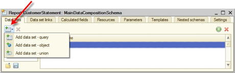
Fig. 413. Adding a new data set
Below, you can see an example of opening the data composition schema wizard window and subsequent serialization of the resulting composition schema in XML.
Procedure ReportEditorCommandBar (Button)
Wizard = New DataCompositionSchemaWizard;
Wizard.SetSchema(GetDataCompositionSchema());
Wizard.Edit(ThisObject);
EndProcedure
Procedure ChoiceProcessing(SelectionValue, Source)
If TypeOf(Source) = Type("DataCompositionSchemaWizard") Then
DataCompositionSchema = Source.GetSchema();
XMLWriter = New XMLWriter;
XMLWriter.SetString();
XDTOSerializer.WriteXML(XMLWriter, DataCompositionSchema, "dataCompositionScheme", "http://v8.1c.ru/8/data composition system/scheme");
Controls.DataCompositionSchemaText.SetText(XMLWriter.Close());
EndIf;
EndProcedureOperation with the data composition schema is divided into the following steps, which include editing of:
-
Data sets
-
Data set fields
-
Data set links
-
Calculable fields
-
Resources
-
Parameters
-
Templates
-
Nested settings
-
Data composition system settings
10.3.5.1. Editing data sets
The data composition system supports editing of the following objects:
-
Query data set
-
Object data set
-
Union data set
-
Query fields
When you add a data set, the application automatically generates a name and data source (if the data source does not exist).
The data composition schema entry field, nested data set, can be described in the query, as well as in the object data set.
You can use nested tables in the query text of an object data set in the {SELECT} and {WHERE} expressions.
SELECT
GoodsReceipt.Date, GoodsReceipt.Number, GoodsReceipt.Vendor, GoodsReceipt.Warehouse, GoodsReceipt.Goods.( LineNumber, Product, Price, Count, Sum
)
{SELECT
Date
Number, Vendor.*, Warehouse.*, Goods.( LineNumber, Product.*, Price, Count, Sum
)}
FROM
Document.GoodsReceipt AS
GoodsReceipt
{WHERE
GoodsReceipt.Date, GoodsReceipt.Number, GoodsReceipt.Vendor.*, GoodsReceipt.Warehouse.*, GoodsReceipt.Goods.( LineNumber, Product.*, Price, Count, Sum
)}In the example above, query fragments describing the fields of nested tables available for settings are shown in bold.
10.3.5.1.1. Editing a query data set
To edit a query data set, create a data query. To do this, you can use the query wizard or edit the query text directly in the data composition schema wizard window.
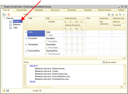
Fig. 414. Query data set
If the AutoFill checkbox is selected, the data composition system automatically fills the data composition schema fields based on the query.
10.3.5.1.2. Editing an object data set
To edit an object data set, add/edit the name of the object containing data or add/edit fields and groupings.
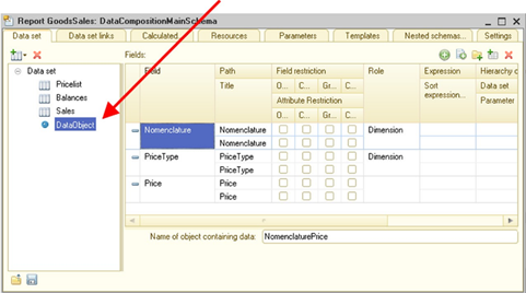
Fig. 415. Object data set
10.3.5.1.3. Editing a union data set
To edit a data set union, edit merged fields from the fields that are subordinate to the data set. You can add created query data sets and objects to a union data set by dragging them with the mouse pointer.
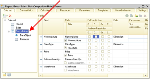
Fig. 416. Union data set
10.3.5.2. Editing data set fields
When you edit fields, you can specify:
-
Field title
-
Field availability restriction
-
Attribute fields availability restriction
-
Field role
-
Field presentation
-
Ordering expression
-
Hierarchy check method (data set and parameter)
-
Field value type
-
Field appearance
Note that you can edit the field role, the presentation, the ordering expression, the parameter, the value type, and the field appearance only at the top level of the data set hierarchy.
If the data set field does not have a title set, the data composition system attempts to generate a field title based on the synonym of the query field. If there is no synonym for the field, the field data path is used as the field title, supplemented with spaces using the algorithm to convert names to synonyms. Synonyms for query fields are obtained only for fields that either have no alias set or are not different from the default alias for this field.
Synonyms for the query field are obtained as follows.
-
If the query does not contain unions:
-
If the query field expression consists of a single field, the synonym is obtained from that field.
-
If a field expression is an aggregate function over a single field, the synonym for the field is derived from this field. For other expressions, it is considered that a synonym cannot be obtained.
-
-
If the query contains unions:
- In all unions, the system searches for a field for which a synonym used as a field synonym can be obtained. If no such field is found, the synonym cannot be obtained.
In the data composition schema wizard, there is an additional column with a checkbox indicating that the field title is set manually. The checkbox is automatically cleared if the field does not have a set title.
When filling fields based on a query, the wizard automatically fills titles of fields without synonyms and of those fields whose alias in the query differs from the default field alias. This way, the checkbox will be automatically selected for such fields.
If this checkbox is cleared, the Title column displays the title to be shown to the user. At the same time, the title in the field is not filled. The Title column for fields that have the checkbox cleared is not edited and is displayed in the disabled text color.
If the developer needs to change the title, they select the checkbox, and the field title text is filled based on the text that was previously displayed in the Title column. If the checkbox is cleared, the wizard clears the title text and starts displaying the automatically generated title in the title.
The field role is initially defined in the query, but you can change it in a separate dialog box.
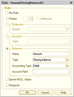
Fig. 417. Field role
For the count field, explicitly specify a reference to the count type in the View parameter.
For the dimension field, specify the path to the parent dimension data in the Dimension parameter.
If the Ignore NULL checkbox is selected, group records for this field will not be included in the result if it contains the NULL value.
In the resulting data set, fields with selected Required checkbox will always be present if at least one field from its data set is used in the settings. For example, you need to get expanded balances by extra dimensions. In this case, if the Extra dimension field is not used in the query, the balances will be collapsed.
You can also edit field ordering expressions, value type, and appearance in a separate dialog box.
10.3.5.3. Editing data set links
In case of multiple top-level data sets, you can set up links between them by one or several fields.

Fig. 418. Data set links
Link source and destination are data sets. Source and destination expressions are data set fields.
10.3.5.4. Editing calculable fields
On the Calculable Fields tab, you can create and edit the following properties/characteristics of calculable fields:
-
Data path
-
Expression
-
Title
-
Availability restriction
-
Presentation expression
-
Ordering expression
-
Value type
-
Appearance
-
Available values
Ordering expressions are edited in a separate dialog box.
10.3.5.5. Editing resources
You can calculate resources by all fields of all data sets and by calculable fields. The left tabular field shows a list of available and unused fields. The right tabular field displays the fields by which the totals and their calculation expressions will be generated.

Fig. 419. Editing resources
By default, the Sum function is set for numeric fields, and the Count function is set for non-numeric fields. Click >> to add all fields of the Number type to resources. Note that you can add multiple lines for a single resource. When the template composer gets an expression for a resource, it checks the target grouping and generates the expression for that grouping.
In the editing dialog box of the Calculate by column, strings with the field name and the Hierarchy keyword are added for fields that can be hierarchically grouped. The expression will be used for hierarchical grouping records by the field specified before the word. When you select a grouping broken down by which a resource can be calculated, you can select both a regular and hierarchical field at the same time.
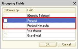
Fig. 420. Calculation of resources by grouping fields
If you have set the resource to be calculated only broken down by a certain grouping (you have selected at least one grouping field in the Calculate by column), this resource is output to the results only for this grouping and its nested groupings.
10.3.5.6. Editing parameters
Parameter editing includes:
-
Parameter name editing
-
Title editing
-
Editing of available parameter types and values
-
Defining the value and availability of the parameter value list
-
Defining the expression
-
Defining the parameter as an available data composition setting field
-
Availability restriction
-
Defining whether the parameter is required
-
Defining whether the parameter is used
-
Specifying editing parameters
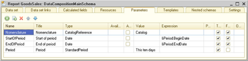
Fig. 421. Editing parameters
If the parameter value is undefined, it is assumed that the value is a zero reference to the specified type. Parameters can use predefined data and enumerations (Designer mode).
Values that can be selected by the user as parameters of the data composition schema are edited in the Available values column. If the checkbox in the Value list is available column is selected, several parameter values can be used.
Note. Note. When you use the StandardPeriod parameter type, consider that the start and end dates of the standard period also contain time. Also, keep in mind that the start date time is 00:00:00, and the end date time is 23:59:59. Therefore, you do not have to use the BEGINOFPERIOD and ENDOFPERIOD functions in the query.
Here is an example of using the required parameter of the data composition schema. Imagine that the Company parameter must be always specified in a report. In the data composition schema, for the Company parameter, the Use property is set to Always, and the Prohibit empty values property is set to True.
When the report is being used, the Use property is unavailable to the user (it is absent), and the empty value is displayed in the usual way marked by a wavy red line. If the user does not fill the parameter value and runs the report for execution, the system will prompt the user to fill the parameter value.
10.3.5.7. Editing templates
To add templates, click Add template on the command bar.
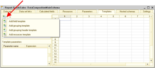
Fig. 422. Template editor
You will be prompted to select one of the following template options:
-
Field template
-
Grouping template
-
Grouping title template
-
Table resources template
For the grouping template and grouping title, you can specify the grouping name/grouping fields, and template type.
For the table resource template, you can specify templates for two groupings at the intersection of which it is located.
The Area tabular field column indicates template area coordinates in the spreadsheet document.
To edit spreadsheet document areas, press Alt + Enter to go to the properties panel. You can edit both cell appearance and contents, as well as its drilldown parameter.
You can edit templates in all languages supported by the application. When you specify a parameter or template for a spreadsheet document cell, the parameters are added to the template and are displayed in the Parameter name column of the Template parameters table field. You can edit the template parameter expression. When loading, template areas are separated by empty lines.
10.3.5.8. Nested schemas
On the Nested schemas tab, you can create and edit nested data composition schemas. Nested schemas edited by the data composition schema wizard can serve as a schema.
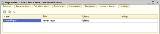
Fig. 423. Nested schemas
10.3.5.9. Settings
The data composition schema contains default data composition settings that can be specified by the developer.
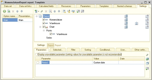
Fig. 424. Editor of data composition schema settings
The way you set up the Auto resource position report defines how resource fields will be displayed:
-
Do not use. In this case, resources are displayed in the order fields are listed on the Selected fields tab.
-
After all fields. In this case, resources are displayed after all fields.
For groupings (or table groupings), the Grouping use case parameter controls the display of additional information after resource fields. If this parameter is not set or is set to Auto, the grouping is responsible for displaying the detailed records.
If the parameter is set to Additional information and is specified in the column grouping, one column will be displayed in the resulting table in this column. It will contain fields specified on the Selected fields tab of this grouping and fields available for display in row grouping. If grouping fields are specified for the column grouping, an error occurs when composing the template. The algorithm for the row grouping is similar, but only one row is displayed instead of a column.
For example, Products are displayed in table rows. Warehouses are displayed in table columns. You want to generate a report on goods inventory in warehouses. You need to display product SKUs after columns with remaining goods. To do this, add grouping without group fields to the table columns and set the Grouping use case parameter to Additional information in the grouping settings. On the Selected fields tab, specify the Product.SKU field.
When this grouping is displayed outside the table, all fields that are available in the grouping are displayed.
For example, if a report contains a grouping with multiple nested groupings If you use a grouping with the Grouping use case parameter set to Additional information, the parent grouping data between groups can be displayed.
For groupings set to Additional information, the following parameters are ignored:
-
Location of grouping fields. Titles of fields displayed in groupings are always displayed at the beginning of the row or column.
-
Number of records.
-
Percentage of records.
-
Placement of totals.
-
Placement of grouping fields.
-
Placement of groupings.
-
Placement of overall totals.
During template composition, if there is a field in a grouping set to Additional information that is unavailable in the grouping or table, an exception is thrown.
10.3.5.9.1. Nested fields
Numeric fields
The application automatically generates nested fields for numeric resources. These fields are calculated automatically and facilitate data retrieval. For example, you can use them to get the percentage ratio of a resource value to the resource value total in all the report data. These fields are listed below.
% in hierarchy group
ID:
PercentInHierarchy
Description:
This field contains the percentage of a resource value in the current hierarchy group. It is 100% in nontable output.% in column or point hierarchy group
ID:
PercentInColumnOrPointHierarchy
Description:
This field contains the percentage of the resource value in the current cell to the value of the resource total at the current hierarchy level of the current grouping for a column or for a point. In nontable output, it is equal to the % in hierarchy group field value.% in row or series group
ID:
PercentInRowOrSeriesHierarchy
Description:
This field contains the percentage of the resource value in the current cell to the value of the resource total at the current hierarchy level of the current grouping for a row or for a series. It is 100% in nontable output.% in grouping
ID:
GroupPercent
Description:
This field contains the percentage of a resource value in the current cell to the value of the resource total in the current grouping. In nontable output, it is always 100%.% in column or point grouping
ID:
ColumnOrPointGroupPercent
Description:
This field contains the percentage of a resource value in the current cell to the value of the resource total in the current group for a column or a point. In nontable output, it is always 100%.% in row or series grouping
ID:
RowOrSeriesGroupPercent
Description:
This field contains the percentage of a resource value in the current cell to the value of the resource total in the current group for a row or a series. In nontable output, it contains the % in grouping field.% in column or point
ID:
ColumnOrPointPercent
Description:
This field contains the percentage of a resource value in the current cell to the value of the resource total for a column or a point. In nontable output, it contains the % total field.% in row or series
ID:
RowOrSeriesPercent
Description:
This field contains the percentage of a resource value in the current cell to the value of the resource total for a row or series. In nontable output, it is always 100%.% total
ID:
OverallPercent
Description:
This field contains the percentage of a resource value in the current cell to the value of the overall resource total in the table. In nontable output, it is always 100%.Fields that contain the Date type as part of their types
The application automatically generates nested fields for fields that contain theDate type among their types. These fields are calculated by the application, which simplifies display of date- and time-related data. For convenience, these fields are divided into three groups: Start dates (BeginDates), End dates (EndDates), and Date parts (DateParts). These fields are listed below.
"Beginning dates" group
Beginning of day
ID:BegOfDay
Description:
Date and time of the beginning of the day.Beginning of week
ID:BegOfWeek
Description:
Date and time of the beginning of the week, considering the First day of the week property of the regional settings of the infobase.Beginning of ten days
ID:BegOfTenDays
Description:
Date and time of the beginning of ten days.Beginning of month
ID:BegOfMonth
Description:
Date and time of the beginning of the month.Beginning of quarter
ID:BegOfQuarter
Description:
Date and time of the beginning of the quarter.Beginning of half year
ID:BegOfHalfYear
Description:
Date and time of the beginning of the half year.Beginning of year
ID:BegOfYear
Description:
Date and time of the beginning of the half year.Beginning of minute
ID:BegOfMinute
Description:
Date and time of the beginning of the minute (if the date includes time).Beginning of hour
ID:BegOfHour
Description:
Date and time of the beginning of the hour (if the date includes time)."End dates" group
End of day
ID:EndOfDay
Description:
Date and time of the end of the day.End Of Week
ID:EndOfWeek
Description:
Date and time of the end of the week, considering the First day of the week property of the regional settings of the infobase.End of ten days
ID:EndOfTenDays
Description:
Date and time of the end of ten days.End of month
ID:EndOfMonth
Description:
Date and time of the end of the month.End of quarter
ID:EndOfQuarter
Description:
Date and time of the end of the quarter.End of half year
ID:EndOfHalfYear
Description:
Date and time of the end of the half year.End of year
ID:EndOfYear
Description:
Date and time of the end of the year.End of minute
ID:EndOfMinute
Description:
Date and time of the end of the minute (if the date includes time).End of hour
ID:EndOfHour
Description:
Date and time of the end of the hour (if the date includes time)."Date parts" group
Day
ID:Day
Description:
Day of the month (number).Day of the week
ID:WeekDay
Description:
Number of the day of the week (as the WeekDay() function returns, the week always starts on Monday).Day of the week name
ID:WeekDayName
Description:
Weekday presentation (1 for Monday, 2 for Tuesday, and so on). Day number is obtained by the WeekDay() function.Day of the year
ID:DayOfYear
Description:
Number for the day of the year.Week of the year
ID:WeekOfYear
Description:
Number of week in the year, considering the First day of the week property of the regional settings of the infobase.Month
ID:Month
Description:
Number of the month of the year.Month name
ID:MonthName
Description:
Month name presentation (1 for January, 2 for February, and so on).Quarter
ID:Quarter
Description:
Number of the quarter.Year
ID:Year
Description:
Year value in 4-digit view (number).Minute
ID:Minute
Description:
Number of the minute.Hour
ID:Hour
Description:
Number of the hour.10.3.5.9.2. System fields
In the list of selected fields, the application generates a dedicated group of system fields (SystemFields) used to define the sequence number of records both in the entire report and within groupings. Remember that system fields are not included in the list of fields that are obtained by expanding an auto field. Therefore, they must be added manually.
Ser. #
ID:
SystemFields.SerialNumber
Description:
Contains the sequence number of the row in the report. Numbering starts with 1.# in group
ID:
SystemFields.GroupSerialNumber
Description:
Sequence number of the row in the current grouping. Numbering starts with 1.Level
ID:
SystemFields.Level
Description:
Current record level. Numbering starts with 1.Level in group
ID:
SystemFields.LevelInGroup
Description:
Current record level in relation to the grouping. Numbering starts with 1.10.3.5.9.3. Parameter fields
The selected fields include a dedicated group named Parameters used to include data composition schemas with the Include in available fields checkbox selected in the report.
10.3.6. Setup options of data composition schema
In the data composition schema, you can define multiple setup options. Setup option is a set of report settings that the developer decided to select separately. These setup options are stored in the data composition schema.
For example, the Dynamics of sales report options can include a chart with sales of goods by periods and a table report with sales of goods broken down by customers. Each report option has its own set of user settings.
When you use a data composition schema for a report, settings described in the schema are provided to the user as standard report options.
You can create a custom report option in 1C:Enterprise mode. This action is recommended for experienced users. In this case, the new report option is stored in the report option storage, from which other users can download a required option.
Use the configuration comparison and merging feature (see Comparing and merging configurations) to compare and merge setting parts.
To import the data composition schema from XML, use standard 1C:Enterprise language tools.
10.3.6.1. Data composition setup option structure
Structure is a certain skeleton of settings. It determines the mutual arrangement of their main elements.
You can access the settings structure using the Structure property of the DataCompositionSettings object. Setup structure elements can include:
-
Groupings
-
Tables (DataCompositionTable)
-
Charts (DataCompositionChart)
-
Nested setup objects (DataCompositionSystemNestedObjectSettings)
Grouping
There are three different types of data in the settings structure to implement the Grouping:-
Groupings (DataCompositionGroup)
-
Table groupings (DataCompositionTableGroup)
-
Chart groupings (DataCompositionChartGroup)
Three types are required to implement the restrictions imposed on the relative placement of structure tree elements: tables and charts cannot include anything but groupings. Accordingly, all grouping objects have the same object model, they differ in the type of nested collection of values and the composition of output parameters.
Grouping fields
The set of fields by which grouping is performed is described by the GroupingFieldsOfDataCompositionSystem object. The Elements property of this object contains a collection of Grouping fields that consists of the GroupingFieldOfDataCompositionSystem objects.Note. Note.When performing grouping by period field, the parent period field is automatically added to the grouping. This field is not an additional period if parent groups have not been grouped by this parent period field.
For example, if grouping is performed in the Recorder field, the SecondPeriod field is automatically added to the grouping.
At the same time, groupings cannot be created according to the attributes of period fields.
Grouping auto field
Before being used, the auto field is converted into a set of grouping fields.The set is formed as follows. Selected fields with the following conditions are taken:
-
They are available for use in grouping fields.
-
They are not resources.
-
They do not depend on other selected fields.
-
They do not depend on already existing grouping fields.
If a field is already included in the data of the grouping field, it is not added again.
Tables
To describe a table in the settings structure, use the TableOfDataCompositionSystem object.Charts
To describe a chart in the settings structure, use the ChartOfDataCompositionSystem object.Nested objects
To describe Nested objects in the settings structure, use the DataCompositionSystemNestedObjectSettings object.The object has the Name property used to identify the nested report in the generated data composition template.
10.3.6.2. Data composition settings properties
Case
A set of fields that are output to composition results. To describe it, use the DataCompositionSelectedFields object. The Elements property of this object contains a collection of selected fields consisting of the DataCompositionSelectedField objects.Selected fields group
It is used to group fields. To describe it, use the DataCompositionSelectedFieldGroup object.Autoselected field
Before being used, the auto field will be converted into a set of selected fields. The assortment of fields in a set depends on the structure item where the auto field belongs and on the structure part where the item is located. For each item, 1C:Enterprise iterates through all the parent items of the report structure and selects the resources and fields from the selected fields of these items using the following rules:-
For groupings and table groupings, auto fields are replaced by:
-
All used fields of this grouping that can be used in the selected fields.
-
Fields that are attributes of its grouping fields.
-
Resources of parent items.
-
Note. IMPORTANT. The application considers only groupings of the No hierarchy or Hierarchy type when iterating.
-
For a chart grouping, resources are not selected. Instead, 1C:Enterprise iterates through all the parent items of the report structure and selects grouping fields from the selected fields of these items, provided that this grouping is of the Hierarchy only type.
-
For groupings of the Detailed records type (grouping, table grouping, or chart grouping), all the used fields except for the fields that are included in higher-level groupings and attributes of those fields are selected from the main selected fields of the setting where the grouping belongs. If the grouping has the Hierarchy only type, its fields and attributes are used in the generation of a selection field set. For a chart grouping, resources are not selected.
-
For the Detailed information type groupings, the selected fields contain non-resource fields that are available in the grouping or parent grouping and the ones in a grouping at the opposite axis for tables.
-
For charts, the auto selected field is replaced by all parent resources.
-
For tables, the auto selected field is converted into a set of resources used by parent items.
Note. Note. If a field is already included in the selected fields, it is not added again.
At that, the fields are added into a set in the following order: first the fields of the grouping's own fields (for groupings), next fields of the global settings (for Detailed records groupings), and finally the resources and fields of the parent items.
Filter
Use it to Filter records in the composition result. Besides, you can use it to Filter formatted records with applied conditional appearance and to create custom selection fields.To describe it, use the DataCompositionFilter object. The Items property of this object contains a collection of filter items that consists of the DataCompositionFilterItem objects.
Filter item group
Use it to group filter items that will order result data. To describe it, use the DataCompositionFilterItemGroup object.Order
Use it to Order records displayed to the result. To describe it, use the DataCompositionOrder object. The Items property of this object contains a collection of Order items that consists of the DataCompositionOrderItem objects.Order Auto Element
Before being used, the auto order item is converted into a set of order items.The set is generated according to the following rules: resources are added unconditionally, fields being grouping field attributes and the grouping field itself are added to the order from non-resource fields. For detailed records, all fields are added. The grouping fields that are not specified in the global sorting are added to the end of the list. If a field is already included in this order, it is not added again.
Conditional appearance
Use it to set up appearance of different result fields. To describe it, use the DataCompositionConditionalAppearance object. The Items property of this object contains a collection of order items that consists of the DataCompositionConditionalAppearanceItem objects.In the data composition appearance of the data composition wizard, the Format and Text parameters are edited as multilingual.
You can define the scope of application for conditional appearance items. Conditional appearance can be used:
-
In groupings
-
In hierarchical groupings
-
In grand totals
-
In field titles
-
In resource field titles
-
In grand total titles
-
In grand total resource field titles
-
In titles
-
In parameters
-
In filters
Formatted fields
Fields to which formatting is applied. To describe them, use the DataCompositionAppearanceFields object. The Items property of this object contains a collection of appearance fields that consists of the DataCompositionAppearanceField objects. If no fields are specified, the appearance will be applied to the entire area.Output parameters
The values of Output parameters define the appearance of respective objects. Inheritance is supported for some parameters. Therefore, the collection of Output parameters for an item can contain parameters that are not related to it, but are used in items that can be inserted into the subordinate part of the settings structure.Data parameters
Data parameter values are usually used in data set filtering queries.Custom fields
You can use Custom fields to expand the set of available fields by defining custom expressions or option sets with conditions of using a particular option.To describe custom fields, use the DataCompositionUserFields object. The Items property of this object contains a collection of custom fields that consists of objects of the following two types:
-
Field-Expression (DataCompositionUserFieldExpression object)
-
Field-Selection (DataCompositionUserFieldCase object).
The field type is determined automatically by the application based on its properties.
Custom field options
Custom field option is a set of alternatives that define the selection field value. To describe them, use the DataCompositionUserFieldsCaseVariants object. The Items property of this object contains a collection of custom selection field options that consists of the DataCompositionUserFieldsVariant objects.Managing auto fields
If one item of the settings structure contains DataCompositionSystemGroupingAutoField, DataCompositionSystemAutoSelectedField, and DataCompositionSystemOrderingAutoItem, they are converted as follows:-
DataCompositionSystemGroupingAutoField
-
DataCompositionSystemAutoSelectedField
-
DataCompositionSystemOrderingAutoItem
10.3.6.3. Available objects
Available objects are a set that defines objects that can be used as nested in the composition. For example, nested reports.
10.3.6.4. Available fields
Available fields are numerous fields that can be used in the data composition setup and will be recognized and properly processed in subsequent composition stages. Available fields vary in use. There are the following field collections:
-
Selection fields (SelectionAvailableFields property)
-
Grouping fields (GroupAvailableFields property)
-
Order fields (OrderAvailableFields property)
-
Data parameter fields (DataParametersAvailableFields property)
-
Filter fields (FilterAvailableFields property)
-
Structure item filter fields that are used in all structure items except for the top one (StructureItemsFilterAvailableFields property)
-
Additional filter fields that are used in conditional appearance (AdditionalFilterAvailableFields property)
All the listed properties contain value collections that consist of the DataCompositionAvailableField objects.
Available fields are listed in a specific order in the data composition schema wizard and in the data composition schema settings of a report. Non-resource fields are followed by resource fields. Their titles are listed alphabetically. System folders are the last in the list.
Available filter field
A special type of available fields is implemented for use in filters. It has all the properties of regular available fields. It also provides sets of available comparison kinds and available field values required to correctly order filter items.
10.3.6.5. Data composition settings composer
The settings composer is represented by the DataCompositionSettingsComposer 1C:Enterprise language object. The object is used to link data composition settings and data composition schema. Based on the data composition schema, the application generates the source of available settings for the settings composer.
If you need to use the source of available settings of one composer in another one, you can get the source of available settings using the GetAvailableSettingsSource() method of the DataCompositionSettingsComposer object.
Below, you can find an example of transferring the source of available data composition settings:
Variable FormParameters;
FormParameters = New Structure;
FormParameters.Insert("SourceOfAccessibleSettings", List.SettingsComposer.GetAvailableSettingsSource());
FormParameters.Insert("Settings", List.SettingsComposer.Settings);
FormParameters.Insert("FixedSettings", List.SettingsComposer.FixedSettings);
FormParameters.Insert("UserSettings", List.SettingsComposer.UserSettings);
OpenForm("CommonForm.SettingsComposerForm", FormParameters);10.3.7. Custom settings of the data composition system
You can select some settings so that the user can edit them in a separate form. This feature is called Custom settings.
Both custom and full settings are used for composition. At the same time, custom settings are "superimposed" on full ones, generating the actual executable settings.
10.3.7.1. Object model of custom settings
The following objects are edited using custom settings:
-
DataCompositionFilter
-
DataCompositionFilterItem
-
DataCompositionFilterItemGroup
-
DataCompositionOrder
-
DataCompositionSelectedFields
-
DataCompositionConditionalAppearance
-
DataCompositionConditionalAppearanceItem
-
DataCompositionSettingsParameterValue
-
DataCompositionGroup
-
DataCompositionTableGroup
-
DataCompositionChartGroup
-
DataCompositionTable
-
DataCompositionChart
-
NestedDataCompositionSchema
-
ElementsCollectionOfDataCompositionStructure
-
DataCompositionTableStructureItemCollection
-
DataCompositionChartStructureItemCollection
These objects have the following properties:
- UserSettingID is used to identify custom settings objects. If this property is set, the object is considered a custom one and is subject to editing in custom settings.
When you interactively mark a setting as a custom one, the application automatically generates a UUID and fills this property with a string presentation of that ID.
-
UserSettingPresentation is a string used to display the presentation in custom settings. In the schema wizard, you can enter presentations in multiple languages.
-
ViewMode is used to define quick settings. More information about this feature will be provided below.
Custom settings in the object model are represented by the DataCompositionUserSettings object. This object has the Items property. This collection contains items of custom settings. Possible object types:
-
DataCompositionFilter
-
DataCompositionFilterItem
-
DataCompositionFilterItemGroup
-
DataCompositionOrder
-
DataCompositionSelectedFields
-
DataCompositionConditionalAppearance
-
DataCompositionConditionalAppearanceItem
-
DataCompositionParameterValue
-
DataCompositionGroup
-
DataCompositionTableGroup
-
DataCompositionChartGroup
-
DataCompositionTable
-
DataCompositionChart
-
DataCompositionNestedObjectSettings
-
DataCompositionSettingStructure
10.3.7.2. Configuring custom settings items
You can select the custom setting item checkbox in the custom item setup form. To open it, execute the Item properties of custom settings command.
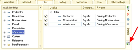
Fig. 425. Open custom setting
In the custom item setup form, you can also specify the presentation that will be used for the item and its editing mode.
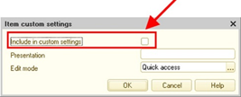
Fig. 426. Custom setting property
In the settings structure list, you can execute the Item properties of custom settings command to set up custom settings for the current structure item. Each structure item has its own customizable items.
| Object | Customizable items |
|---|---|
| Report | · Selected fields · Order · Filter · Conditional appearance · Grouping items |
| Grouping/ table grouping/ chart grouping | · Grouping · Selected fields · Filter · Order · Conditional appearance · Items of nested groupings |
| Chart | · Chart · Selected fields · Conditional appearance · Items of series groupings · Items of point groupings |
| Table | · Table · Selected fields · Conditional appearance · Items of row groupings · Items of column groupings |
| Nested schema | · Nested report · Selected fields · Filter · Order · Conditional appearance · Grouping items |
Based on the location where the Properties command of a custom setting item is called, the following settings can be changed:
-
If you call the command in the filter list, you can change custom settings for the current filter item/filter item groups.
-
If you call the command in the list of output parameters and data parameters, you can change custom settings for the current parameter.
-
If you call the command in the conditional appearance list, you can change custom settings for the current conditional appearance item.
Besides, the Custom settings command called in the structure table opens a form that displays custom settings with their default values.
10.3.7.3. Editing custom settings
The UserSettings object is edited in a table (see fig. 427).
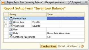
Fig. 427. Custom settings editor
Note. Tip. From all the variety of settings offered by the data composition system, it is recommended that you define settings that manage the report by the end user as custom ones. It is assumed that the user will only operate these settings.
For example, in a query that is used as a data set for a report, there are numerous fields that can be used for filtering. However, the report developer believes that some filter items are used most often. Therefore, it is reasonable to mark them as custom settings. This way, the user will be able to edit both "special" filter items (the Goods row in fig. 427) and the entire filter (the Filter row in fig. 427).
It also makes sense to mark the following settings as custom ones:
-
Period or date for almost all reports.
-
Groupings and conditional appearance for table reports.
-
Value of accounts for accounting reports, and so on.
At the same time, the developer will select custom settings for each report or report option.
10.3.7.4. Quick custom settings
The developer can select some frequently used custom settings (for example, filter by product in the Goods inventory report or filter by company in an accounting report) to edit them directly in the report form. You can select certain custom settings to include them in the quick settings. To do it, set the ViewMode property to Quick access. You can place such settings on the report form for quick access.
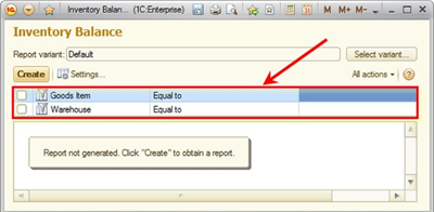
Fig. 428. Quick custom settings
The table used to edit user settings also has the ViewMode property, which determines whether to show all custom settings or only quick ones.
If the user is not satisfied with the current quick custom settings, they can change them, for example, by excluding the custom settings that they do not intend to use often.
To do this, the user must click More actions – Customize displayed settings... orAll actions – Customize displayed settings... in the report settings editor window.
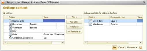
Fig. 429. Edit quick custom settings
The left part of the form shows all the custom settings that can be selected as quick ones. The right part of the form displays settings that are currently being edited in the report form.
In the filter or conditional appearance editor forms, you can find commands to edit the properties of a custom settings item. This way, the user can transfer frequently used filter items or conditional appearance items to the quick custom settings.
You can also add or remove quick custom settings in the settings editor form using the Edit in report form column. This column is not displayed in the form by default, so the user must enable it by clicking More actions – Edit form... orAll actions – Edit form... in the settings editor window.
In this case, you cannot add new settings, but you can quickly change the components of existing settings.
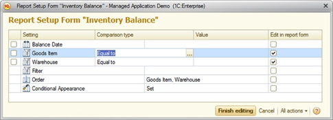
Fig. 430. "Edit in report form" column
10.3.7.5. Settings composer
The Settings composer has the UserSettings property. This property contains values of edited custom settings. This property cannot be written programmatically. In addition, the settings composer has the LoadUserSettings() method that loads custom settings values passed as the method parameter.
Use the GetSettings() method to get a copy of current settings (considering custom settings).
Use the LoadSettings() method to load settings passed to the settings composer (custom settings are also overwritten based on the passed data).
10.3.7.6. Filling custom settings values
When you fill values of custom settings for different setting items, correspondingly filled items are added to the custom settings.
The UserSettingID property and properties that are actually edited in custom settings are filled in the corresponding custom items for the following types: DataCompositionFilterItem, DataCompositionFilterItemGroup, DataCompositionConditionalAppearanceItem, DataCompositionParameterValue, DataCompositionGroup, DataCompositionTableGroup, DataCompositionChartGroup, DataCompositionTable, DataCompositionChart, and NestedDataCompositionSchema.
An object of respective type is created for the following types: DataCompositionFilter, DataCompositionConditionalAppearance, DataCompositionOrder, and DataCompositionSelectedFields. Element whose ViewMode property is not set to Inaccessible are added to the object collection.
There are exceptions:
-
Items that are marked as custom ones are not added. For example, a custom filter item will not be added to a custom filter.
-
Items that contain custom items are not added. For example, a condition group will not be added if it contains custom items.
-
For nested items, the ViewMode property is not analyzed. Whether they are added or not depends on their parent items.
The DataCompositionSettingStructure object, to which already existing groupings in the structure are added, is created for the following types: DataCompositionStructureItemCollection, DataCompositionTableStructureItemCollection, and DataCompositionChartStructureItemCollection. Only groupings with set grouping fields are placed (detailed records are not placed). Placement of groupings is performed before meeting detailed records, branching, table, chart, nested schema, unused grouping, or grouping with custom structure.
10.3.7.7. Applying custom settings
To apply custom settings to the main settings, use the GetSettings() method of the settings composer. This will trigger the following actions:
-
Content of items is copied to respective custom setting items for the following types: DataCompositionFilterItem, DataCompositionConditionalAppearanceItem, and DataCompositionParameterValue.
-
Items located in the main settings and marked as Inaccessible remain unchanged for the following types: DataCompositionFilter, DataCompositionConditionalAppearance, DataCompositionOrder, and DataCompositionSelectedFields. Items from custom settings are transferred to main settings. For Filter, SelectedFields and ConditionalAppearance, they are added to the end of collection. For Order, they are added to the beginning of the collection.
-
The Use property is set in the corresponding item of main settings based on the Use of custom settings item flag for the following types: DataCompositionFilterItemGroup, DataCompositionGroup, DataCompositionTableGroup, DataCompositionChartGroup, DataCompositionTable, DataCompositionChart, and DataCompositionNestedObjectSettings.
-
For the DataCompositionSettingStructure type, respective groupings are searched for in the structure item of main settings and are placed in the correct order. Missing groupings are created. Groupings that are not found in the custom settings or groupings that are disabled by the user are not deleted. They are marked in a special way. This allows you to save them so that you can use them in the future. User groupings with an empty set of fields (detailed records) are ignored when applied.
10.4. Data composition template
The data composition template is represented by the DataCompositionTemplate 1C:Enterprise language object and consists of numerous other nested objects. The data composition template instructs the data composition system on how to compose data. The data composition template already contains description of area templates, text of executable queries, grouping arrangement, and so on.
10.4.1. Data composition template sections
Each data composition template contains a set of objects that describes a certain section. Consider these sections.
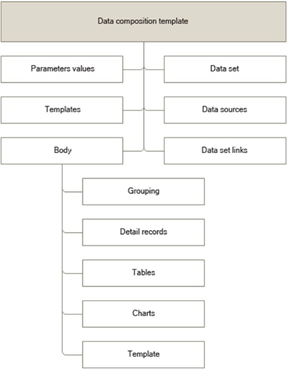
Fig. 431. Data composition template sections
Data sources
The data composition template can include multiple descriptions of data sources.
A data source is a source to retrieve data from. The 1C:Enterprise infobase serves as a data source.
Data sources are described in the DataSources template property, which contains a value collection that consists of the DataSource elements of DataCompositionTemplate.
You can create multiple data sources that use the connection string to one infobase.
Data sets
Data sets of the data composition template contain a description of data to be retrieved for data composition.
They are described in the DataSets property of the data composition template.
Multiple data sets are allowed.
A nested data set is processed as a regular data set. Nested data sets are always linked to their parent datasets. If a filter condition is specified for a nested data set, the nested data set link to its parent data set is considered internal.
Data set field of data composition template
A data set can contain descriptions of fields available to this data set. Fields that are not described in the data set are unavailable. If some field is present in the data set query, but not in the description of data set fields, the field will be unavailable for use.
You can describe data set fields in the Fields data set property, which contains a collection of values that consists of the DataCompositionTemplateDataSetField elements.
Parameter values of data composition template
Data composition templates can contain parameters in any expressions present in them.
You can describe parameter values in the ParameterValues property of data composition template. The property contains a collection of values that consists of the DataCompositionTemplateParameterValue elements.
Data set links of data composition template
Data sets in the data composition template can be linked to each other. Data set links are described in the data composition template.
You can describe them in the DataSetLinks property of data composition template. This property contains a collection of values that consists of the DataCompositionTemplateDataSetLink elements.
Area templates of data composition template
When composition is performed, area templates are displayed as its result. These area templates are also located in the data composition template.
Parameter values are described in the Templates property of data composition template. This property contains a collection of values that consists of the DataCompositionTemplateAreaTemplateDefinition elements.
Data composition template body
Previous data composition template sections contained information on data sources. The instruction on how to compose data is located in the data composition template body. The data composition template body consists of elements.
The following types of elements can be used:
-
Grouping describes the grouping to be displayed in the result.
-
Detailed records describe detailed records of the data set that are displayed in the result.
-
Table describes the table displayed in the result.
-
Chart describes the chart displayed in the result.
-
Template describes the templates used in output.
Table grouping
It describes a table grouping and is represented by the DataCompositionTemplateTableGroup 1C:Enterprise language object.
A table grouping contains the same properties as a regular grouping, with the following differences:
-
The table grouping body and the hierarchical table grouping body can contain only those elements that are contained in the table body. That includes only table groupings, detailed table records, and table grouping templates. The hierarchical body can additionally contain a hierarchical grouping of the table indicating the place where the hierarchical records of the grouping will be displayed.
-
Table grouping templates are used as header and footer templates.
-
The following properties can be used:
-
OverallsTemplate specifies the template of the DataCompositionTemplateTableGroupTemplate type used to output overall results by grouping.
-
OverallsPlacement contains overall location for the grouping of the DataCompositionTotalPlacement type.
-
Detailed table records
They describe Detailed table records and are represented by the DataCompositionTemplateTableRecords 1C:Enterprise language object.Table grouping template
It describes templates used to output a table grouping and is represented by the DataCompositionTemplateTableGroupTemplate 1C:Enterprise language object.Chart grouping
It describes chart groupings and is represented by the DataCompositionTemplateChartGroupBody 1C:Enterprise language object.A chart grouping contains the same properties as a regular grouping, with the following differences:
-
The chart grouping body and hierarchical chart grouping body can contain only chart grouping templates and chart groupings. The hierarchical body can additionally contain a hierarchical chart grouping indicating the place where the hierarchical records of the grouping will be displayed.
-
There are no header and footer templates.
Chart grouping template
It describes the charts used to output a chart grouping and is represented by the DataCompositionTemplateChartGroupTemplate 1C:Enterprise object.10.4.2. Area templates
Area template is a declarative description of output data location, as well as its visual appearance required to output data in documents of different formats.
There are several fundamentally different area templates:
-
Actual area template
-
Chart area templates
You can see the template structure in fig. 432.
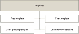
Fig. 432. Template structure
In 1C:Enterprise language, the area template is represented by the DataCompositionAreaTemplate object. This object is a collection of the DataCompositionAreaTemplateTableRow objects.
10.4.2.1. Area template structure
As mentioned above, the area template is a collection of objects of the DataCompositionAreaTemplateTableRow type. Table Row is a collection of cells located horizontally from left to right. Therefore, several subsequent table rows of the data composition area form a rectangular table.
Table cell collection
This object is a collection of table row cells. To describe it, use the DataCompositionAreaTemplateTableCells 1C:Enterprise language object. Collection elements are table cells that are objects of the DataCompositionAreaTemplateTableCell type.Table cell is a rectangular area that is used for data output to documents of different formats. Such cell can contain displayed fields, text, or appearances.
Template element collection
Template element collection is represented by the DataCompositionAreaTemplateItems object and is a collection of fields that are objects of the DataCompositionAreaTemplateField type. These objects can be located in the collection in any order. The data contained in these objects is used in various document formats.Field
This element is a Field displayed in a table cell or in a list item. A Field can contain an arbitrary value and its appearance. To describe fields, use the DataCompositionAreaTemplateField 1C:Enterprise language object.Table cell appearance
It is a collection of objects that describe Table cell appearance. To describe it, use the DataCompositionAreaTemplateTableCellAppearance 1C:Enterprise language object.Field appearance
It is a collection that contains only one object: the Format appearance element. To describe it, use the DataCompositionAreaTemplateFieldAppearance 1C:Enterprise language object.10.4.2.2. Template structure of chart areas
There are three types of chart area templates:
-
Chart template: object of the DataCompositionAreaTemplateChartTemplate type.
-
Chart resource template: object of the DataCompositionAreaTemplateChartResourceTemplate type.
-
Chart grouping template: object of the DataCompositionAreaTemplateChartGroupTemplate type.
When you create chart templates, one chart template, one chart resource template, and several chart grouping templates are generated. The number of grouping templates corresponds to the number of points and series in the chart.
Principle of operation
Area templates are used to output reports to documents of various formats. The area template is an integral part of data composition template definition: the object of the DataCompositionSchemaTemplateDescription type.To display values of report fields in cells or items of the area template list, you need to assign to the Value property of the data composition area field (object of the DataCompositionAreaTemplateField type) the value of DataCompositionAreaTemplateParameter type with the parameter name. Add the parameter to the list of parameters of the template definition. Assign the parameter name as a name, and specify the name of the output field or expression using expression language of the data composition system as an expression.
Chart template
It is used to describe the chart type. To describe it, use the DataCompositionAreaTemplateChartTemplate 1C:Enterprise language object.Chart resource template
Chart resource template is used to generate chart values. To describe it, use the DataCompositionAreaTemplateChartResourceTemplate 1C:Enterprise language object.Chart grouping template
Chart grouping template is used to generate chart points and series. To describe it, use the DataCompositionAreaTemplateChartGroupTemplate 1C:Enterprise language object.10.4.3. Appearance template
Appearance template is a declarative description of predefined report areas. These descriptions are used by the template areas generator when generating area templates based on items of data composition settings.
To create an appearance template interactively, select the Data composition appearance template type in the template wizard and click Done. This opens the appearance template window.
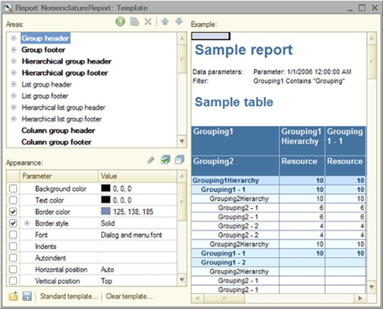
Fig. 433. Appearance template window
The wizard window consists of a list of appearance areas, a table of appearance settings, and the Example spreadsheet document field to display the result of selected settings.
Non-empty template areas are displayed in bold.
You can use the drag and drop context menu to copy appearance parameters from one area to another or replace them.
Click Standard template if you want to load an already prepared template from the standard template list, which also includes common configuration templates.
Click Clear template to remove template appearance.
To configure appearance settings:
-
Select an appearance area.
-
In the settings table, select the parameters whose appearance you want to changed and specify required appearance values.
-
Control the result of made changes in the Example field.
If you want to display several grouping levels in the report, create subordinate areas based on the number of grouping levels in the area list for each area with levels. To create an area level, specify the area and click Add in the command bar. Add a row to the area list and name it LevelN, where N represents the grouping level number. The grouping level appearance is selected as described above.
Note. Note. If multiple levels are specified, deleting a grouping level always removes the lowest level of the current area, regardless of which level is selected in the list.
Appearance template structure
Each template consists of a number of template areas. The template area has a name, which is a row from the template area list that indicates the area to which the template must be applied, and a collection of appearance items.Appearance item has two properties:
-
Level: a positive number. If the level is 0, appearance is applied by default to all area templates of a certain type.
-
Appearance: a collection that contains the names of appearance properties and their values.
In 1C:Enterprise language, the appearance template is represented by the object of the DataCompositionAppearanceTemplate type.
Data composition appearance template
This object is a collection of areas of appearance template. This collection is implemented in the form of parameter values. The parameter name is an area name. The area name is a predefined string from the area list. The parameter value is the object of the DataCompositionAppearanceTemplateArea type.Data composition appearance template area
This object is a description of a predefined area and is a collection of appearance template area elements that are objects of the DataCompositionAppearanceTemplateAreaItem type.Element of appearance template area of data composition
This object is a description of the template area for a specific hierarchy level. If the level number is 0, the appearance template is applied to all areas of that type.
10.4.4. Template area generator
Use the template area generator to dynamically generate templates of data composition areas used to output data composition results to documents of different formats. The template area means a declarative description displayed data location and its appearance.
The template area generator operation can be divided into the following steps:
-
Generation of common report templates
-
Generation of grouping templates
-
Placement of groupings
-
Placement of output grouping fields
-
Application of the appearance template
-
Application of conditional appearance settings
-
Merging of cells
Let us review each operation stage of the area template generator.
Generation of common report templates
At this stage, the template area generator creates common templates based on the data composition settings. The type and number of templates depend on the data composition item type.
Grouping template
A special template is generated for the grouping a grouping header. This template contains the names of output fields on the left and the names of output resource fields on the right, for example:
| Counterparty | Counterparty.Code | Count | Sum |
| Products | Products.Code | Products.Description |
Table template
The following template group is generated for the table:
- Table header template. This template contains names of output fields of table rows, for example:
| Counterparty | Counterparty.Code | |
| Products | Products.Code | Products. Description |
- Totals template by rows. This template contains a special word Total and names of resource fields if they are displayed horizontally, for example:
| Total | |
| Count | Sum |
- Totals template by columns. This template contains a special word Total and names of resource fields if they are displayed vertically, for example:
| Total | Count |
| Sum |
- Grand totals template. This template contains resource fields output in the table and required for display in the grand totals table, for example:
| Presentation( Sum(Sales.CountTurnover)) | Presentation( Sum(Sales.AmountTurnover)) |
Placement of these templates inside the table is shown below.
| Table header | Column Area | Totals template by rows |
| Row area | Resource area | Totals area by rows |
| Totals template by columns | Totals area by columns | Grand totals template |
Placement of totals templates by rows and by columns is managed by the GrandTotalsHorizontalPlacement and GrandTotalsVerticalPlacement properties, respectively. The following grand totals placement options are possible:
- No. Grand totals are not displayed.
| Table header | Column area |
| Row area | Resource area |
- Start. Grand totals are displayed in the first column or in the first row of the table, respectively.
| Table header | Totals template by rows | Column Area |
| Totals template by columns | Grand totals template | Totals area by columns |
| Row area | Totals area by rows | Resource area |
- End. Grand totals are displayed in the last column or the last row of the table, respectively.
| Table header | Column Area | Totals template by rows |
| Row area | Resource area | Totals area by rows |
| Totals template by columns | Totals area by columns | Grand totals template |
- BeginAndEnd. Grand totals are displayed in the first column/row and in the last column/row of the table.
| Table header | Totals template by rows | Column Area | Totals template by rows |
| Totals template by columns | Grand totals template | Totals area by columns | Grand totals template |
| Row area | Totals area by rows | Resource area | Totals area by rows |
| Totals template by columns | Grand totals template | Totals area by columns | Grand totals template |
- Auto. Column totals are located in the last row, and row totals are displayed in the last column.
Chart template
The template contains the appearance properties of the chart.
Generation of grouping templates
There are three grouping types in the data composition setting:
-
Grouping
-
Table grouping
-
chart grouping.
A separate set of area templates is generated for each grouping type. However, placement of groupings relative each other, placement of output fields inside grouping areas, and placement of resource fields are performed in the same way. The generation process of any grouping area template is divided into several stages.
Defining the grouping template type. Grouping template type is retrieved from the DataCompositionGroupTemplateType parameter of the DataCompositionOutputParameterValues object. This property makes sense only for simple groupings that are not included into a table or chart. The following placement options of selected fields are possible:
-
Auto. Location of selected fields is defined automatically. If a grouping contains a nested table, a chart, a nested report or a grouping with the Vertical grouping template type, selected fields will be arranged vertically. Otherwise, horizontally.
-
Horizontal. Selected fields are located horizontally, one after another from left to right.
| Counterparty | Counterparty.Code | |
| Products | Products.Code | Products.Description |
| Aleks-2002 | 00009 | |
| 1C:Accounting 8 | 00013 | 1C:Accounting 8 |
- Vertical. Selected fields are located vertically, one under another.
| Counterparty | Aleks-2002 |
| Counterparty.Code | 00009 |
| Products | 1C:Accounting 8 |
| Products.Code | 00013 |
| Products.Description | 1C:Accounting 8 |
Placement of groupings relative to each other. Placement of groupings relative to each other is controlled by the GroupFieldsPlacement parameter of the DataCompositionOutputParameterValues object. The following placement options are possible:
- Together. Groupings are located one under another. For example, for grouping by counterparty or products.
| Counterparty | Counterparty.Code | |
| Products | Products.Code | Products.Description |
| Aleks-2002 | 00009 | |
| 1C:Accounting 8 | 00013 | 1C:Accounting 8 |
- Separately. Each grouping is located in a separate area. Groupings are located one after another from left to right. Output grouping fields are also displayed in nested groupings.
| Counterparty | Counterparty.Code | Products | Products.Code | Products.Description |
| Aleks-2002 | 00009 | |||
| Aleks-2002 | 00009 | 1C:Aspect 7.7 | 00015 | 1C:Aspect 7.7. Compact Trading System |
- SeparatelyAndInTotalsOnly. Each grouping is located in a separate area. Groupings are located one after another from left to right. Output fields are displayed only in this grouping.
| Counterparty | Counterparty.Code | Products | Products.Code | Products.Description |
| Aleks-2002 | 00009 | |||
| 1C:Aspect 7.7 | 00015 | 1C:Aspect 7.7. Compact Trading System |
-
Placement of output fields. There are two types of fields: actual output fields (field-owners and/or their attributes) and resource fields. The output of these fields has significant differences.
-
Field output. As mentioned above, there are fields-owners and fields-attributes. Fields-owners are displayed in the area template according to their order in the data composition setting. Placement of fields-attributes is controlled by the AttributePlacement special parameter of the DataCompositionOutputParameterValues object. The following placement options are possible:
- Together. Attribute fields are located together in a separate column and are comma-separated upon output.
| Counterparty | Counterparty.Code |
| Products | Products.Code, Products.Description |
- Separately. Each attribute field is located in a separate column.
| Counterparty | Counterparty.Code | |
| Products | Products.Code | Products.Description |
- WithOwnerField. Attribute fields are located in one column with their owner field. They are comma-separated upon output.
| Counterparty, Counterparty.Code |
| Products, Products.Code, Products.Description |
- SpecialPosition. Attribute fields are located in a special column. The column is located to the right of other grouping columns.
| Counterparty | Counterparty.Code |
| Products | Products.Code, Products.Description |
-
Output of fields located in folders. Placement of these fields is controlled by the Folder location property. The following placement options are possible:
- Auto. Fields are displayed depending on the grouping type. For simple groupings, fields are displayed horizontally. For table groupings, they are displayed vertically.
| Counterparty | ||
| Products | Products Attributes | |
| Products.Code | Products.Description | Products.MainSupply |
| Counterparty | |
| Products | Products Attributes |
| Products.Code | |
| Products.Description | |
| Products.MainSupply |
- Horizontally. Fields are displayed horizontally from left to right.
| Counterparty | ||
| Products | Products Attributes | |
| Products.Code | Products.Description | Products.MainSupply |
- Vertically. Fields are displayed vertically one under another.
| Counterparty | |
| Products | Products Attributes |
| Products.Code | |
| Products.Description | |
| Products.MainSupply |
- InSeparateColumn. Fields are displayed in a separate column located to the right of other columns.
| Counterparty | Counterparty.Code | |
| Products | Products Attributes | |
| Products.Code | Products.Description | Products.MainSupply |
- Together. Fields are displayed together. They are comma-separated upon output.
| Counterparty | |
| Products | Products Attributes |
| Products.Code, Products.Description, Products.MainSupplier |
-
Output of resource fields. Placement of resource fields is controlled by the ResourcePlacement property of the OutputParameters object. The following placement options are possible:
-
Horizontally. Resource fields are displayed horizontally from left to right.
-
Vertically. Resource fields are displayed vertically one under another.
-
If the folder title is undefined, there is no place for it in the template. In this case, fields are displayed based on the value of the Folder location property.
Applying appearance templates
After groupings and fields are arranged, the appearance template is applied to the generated area. It is required to add previously defined appearance properties to all area template items, for example BackColor or TextColor. Note that there are numerous appearance templates of areas.Applying conditional appearances
After the appearance template is applied, conditional appearances are applied to the area template. Applying conditional appearance means that appearance properties with logical expressions are added to the area template. After logical expression calculation, the system selects the appearance property value to be applied.Merging cells
Once the area template is generated, it may contain empty cells. These cells must be merged to better represent the area template. The following cell placement options are possible.- Empty cells are located to the right of filled cells. Cells on the right are merged with cells on the left.
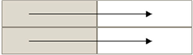
Fig. 434. Empty cells on the right
- Empty cells are located below filled cells. Cells below are merged with cells above.
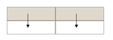
Fig. 435. Empty cells below
- Empty cells are located on the right and under filled cells. Cells on the right are merged with cells on the left. After that, cells below are merged with cells above.
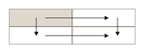
Fig. 436. Empty cells below and on the right
10.4.5. Generating data composition templates
Data composition templates are generated based on the data composition schema and settings. The report developer creates the data composition schema. The user configures the settings.
To generate a composition template, use the DataCompositionTemplateComposer 1C:Enterprise language object.
This object does not have properties and has only one method: Execute(). The data composition schema, data composition settings, variable (into which the DetailsData object is placed), and appearance template are passed as method parameters. This method returns the created data composition template.
During the operation, the template composer:
-
Creates a composition template.
-
Modifies queries for data sets to obtain required for user information and places them in the composition template.
-
Generates filters in the query text or data set description.
-
If necessary, it generates data sets to retrieve and check the hierarchy.
-
Generates required parameters with values set by the user in the data composition template.
-
Fills items of the data composition template body, places groupings, templates, and other items there, and fills their parameters.
-
Uses the template area generator (see Template area generator). If an appearance template is specified (the fourth parameter), it will be applied to set up the appearance of the template being generated.
-
If the third parameter is specified, it creates the DetailsData object and places it into the passed variable. Use the object created this way for composition processor operation and during drilldown processing.
When generating the data composition template, the template composer analyzes the value of the Grouping parameter of the EvalExpression() function. If the parameter contains the name of the grouping in the settings, the template composer leaves this name unchanged. Otherwise, among the parent groupings of the current grouping, the template composer searches for the grouping that contains in the grouping fields all the fields that are specified in the Grouping parameter of the EvalExpression() function, and inserts the name of the found grouping into this parameter.
For example, if the EvalExpression() function parameter is the Products, ProductsCharacteristic string, the template composer will find the grouping by the Products and ProductsCharacteristic fields and will insert the name of the found grouping into the generated template. In this case, the grouping is searched for among the groupings that are available in the place of grouping evaluation. So, if the template composer generates an expression for a table cell, the grouping search will be performed in the column groupings where the cell is displayed, in the row groupings where the cell is displayed, and in the groupings where the table is nested. This way, the search is performed for groupings to which the EvalExpression() function can be applied. If several of them are found, the closest grouping is selected. In the table, the grouping is searched in the row in the first place. After that, the grouping is searched in the column. Finally, the grouping is searched above the table.
If the grouping is not found, the expression is replaced with NULL.
Actually, this allows you to use EvalExpression() in custom settings indicating groupings by grouping field names instead of grouping names.
Example:
DataCompositionSchema = GetDataCompositionSchema();
ExecutableSettings = GetExecutableSettings();
TemplateComposer = New DataCompositionTemplateComposer;
CompositionTemplate = TemplateComposer.Execute(DataCompositionSchema, ExecutableSettings);The generated data composition template can be used for execution, that is, for obtaining the result.
10.5. Data composition processor
Execution of data composition is performed using the 1C:Enterprise application DataCompositionProcessor object.
The data composition template is passed to the data composition processor.
Operation with the data composition processor is simple. After setting a data composition template for the data composition processor, you can sequentially get resulting items of data composition from this object. After that, you can, for example, output them to a spreadsheet document or save them for further use.
Below is the example of operation with the data composition processor.
Controls.SDResultSpreadsheetDocument.Clear();
DCTemplate = GetCompositionTemplate();
DCProcessor = New DataCompositionProcessor;
DCProcessor.Initialize(DCTemplate);
OutputProcessor = New DataCompositionResultSpreadsheetDocumentOutputProcessor;
OutputProcessor.SetDocument(Controls.SDResultSpreadsheetDocument);
OutputProcessor.BeginOutput();
While True Do
DCResultElement
= DCProcessor.Next();
If DCResultElement = Undefined Then
Break;
EndIf;
OutputProcessor.OutputItem(DCResultElement);
EndDo;
OutputProcessor.EndOutput();When initializing the data composition processor, you can additionally specify:
-
Object external data sets structure that contains the external data set as a key, and data set as a value.
-
Drilldown data. An object with drilldown information.
-
Option to use external functions. A flag that shows whether the functions of configuration common modules can be used in expressions.
10.6. Functional options and report field view rights
When receiving the default report settings, the data composition system automatically performs the following actions with the settings:
-
If the user does not have the right for interactive view of some field or this field is connected with the disabled functional options, this field becomes unavailable for user setting. That means that it will be hidden from the list of available fields.
-
If a field is linked to an attribute whose type is disabled by a functional option, this field is removed from the list of available fields.
-
The query table and the attributes of this table become unavailable if the functional option disables the configuration object that forms the table.
-
If a field that the user does not have permission to view or a field that is associated with a disabled functional option is used in a custom field, such custom field is removed and cannot be used for filtering.
-
A data composition system field is considered inaccessible if all fields used in the field expression are associated with disabled functional options or fields unavailable for viewing. All fields included in the field expression in the query are considered, except for the fields specified in the conditions of queries and fields in the WHEN section of the selection operation (CASE WHEN ELSE END). Expressions from unions, if any, are considered as well.
-
All fields that the user does not have permission to view and fields that are associated with disabled functional options are removed from the grouping fields. If after deleting a grouping field, the grouping does not have a single enabled grouping field, the whole grouping is removed. In this case, the grouping contents (if, for example, the grouping includes a table) replace it.
-
If a row grouping or column grouping is removed from a table, and the table has no more groupings left, this table is deleted.
-
If a series grouping or point grouping is removed from a chart, and the chart has no more groupings left, this chart is deleted.
-
All fields that the user does not have permission to view and fields that are associated with disabled functional options are removed from orderings.
-
All fields that the user does not have permission to view and fields that are associated with disabled functional options are removed from formatted fields of conditional appearance items. If a conditional appearance item has no more enabled formatted fields after deleting a formatted field, this conditional appearance item is also deleted.
-
If a conditional appearance item has been filtered by a field for which the user does not have a view right or a field associated with disabled functional options, such conditional appearance item is deleted.
If the field was previously available and the user saved the setting in any way, and later (when the field became unavailable) loads the setting, the fields will not be automatically deleted from the setting. This is done to allow the user to replace unavailable fields with other fields or remove them manually from settings.
If the CheckFieldsAvailability parameter is set to True when performing the Execute() method of the DataCompositionTemplateComposer object, field availability for the current user and field availability in the enabled functional option are checked. If an unavailable field is used in the settings, an exception is thrown. If the parameter value is set to False, the check will not be performed.
Note. Note. If a report is executed from an automatically generated form, field availability for the current user and field availability in the enabled functional option are checked.
10.7. Data composition result
Data composition result is represented by a set of data composition result items. Data composition result does not exist as a separate 1C:Enterprise language object. Only a set of data composition items exists and forms the result.
If necessary, you can place data composition result items in some universal collection of values, for example, in an Array. This way, you can manipulate the result as a single whole.
To get result items, use the DataCompositionProcessor object. You can also create and fill them using 1C:Enterprise language tools.
You can output data composition result items to a spreadsheet document using the output processor.
Let us review an example of data items.
Item 1
| Property | Value |
| Item type | Start |
| Templates | TableHeader ColumnTitle RowTitle Resources |
| Placement of nested items | Vertically |
Item 2
| Property | Value |
| Item type | Start |
| Placement of nested items | Horizontally |
Item 3
| Property | Value |
| Item type | BeginEnd |
| Template name | TableHeader |
Item 4
| Property | Value |
| Item type | BeginEnd |
| Template name | ColumnTitle |
Item 5
| Property | Value |
| Item type | End |
Item 6
| Property | Value |
| Item type | Start |
| Placement of nested items | Horizontally |
Item 7
| Property | Value |
| Item type | BeginEnd |
| Template name | RowTitle |
Item 8
| Property | Value |
| Item type | BeginEnd |
| Template name | Resources |
Item 9
| Property | Value |
| Item type | End |
Item 10
| Property | Value |
| Item type | End |
The output result of such items must look as follows:
| TableHeader | ColumnTitle |
| RowTitle | Resources |
If item 2 contained the TableHeader and RowTitle templates, item 3 would use a template from that item, but item 7 would use a template from item 1, as item 2 ends with item 5.
You can save result items in XML using standard tools, for example:
XMLWriter = New XMLWriter;
XMLWriter.SetString();
XMLWriter.WriteStartElement("result");
DataCompositionTemplate = GetCompositionTemplate();
DataCompositionProcessor = New DataCompositionProcessor;
DataCompositionProcessor.Initialize(DataCompositionTemplate);
While True Do
DataCompositionResultItem = DataCompositionProcessor.Next();
If DataCompositionResultItem
= Undefined Then
Break;
EndIf;
XDTOSerializer.WriteXML(XMLWriter, DataCompositionResultItem, "item", "http://v8.1c.ru/8/data
composition system/result");
EndDo;
XMLWriter.WriteEndElement();
Controls.DataCompositionResult.SetText(WriteXML.Close());10.7.1. Composition result output to a spreadsheet document
To output a report to a spreadsheet document, use the DataCompositionResultSpreadsheetDocumentOutputProcessor object.
Data composition result items can be obtained using the data composition processor or generated by other tools.
Review an example of data composition result output to a spreadsheet document:
Controls.SDResultSpreadsheetDocument.Clear();
DataCompositionTemplate = GetCompositionTemplate();
DataCompositionProcessor = New DataCompositionProcessor;
DataCompositionProcessor.Initialize(DataCompositionTemplate);
OutputProcessor = New DataCompositionResultSpreadsheetDocumentOutputProcessor;
OutputProcessor.SetDocument(Controls.SDResultSpreadsheetDocument);
OutputProcessor.BeginOutput();
While True Do
DataCompositionResultItem = DataCompositionProcessor.Next();
If DataCompositionResultItem
= Undefined Then
Break;
EndIf;
OutputProcessor.OutputItem( DataCompositionResultItem);
EndDo;
OutputProcessor.EndOutput();You can also use the Output() method of the OutputProcessor object. You can specify DataCompositionProcessor as the method parameter. In this case, the composition result will look as follows:
OutputProcessor.Output(DataCompositionProcessor);Data composition processor fixes the table header if one table or one grouping is output to the report (possibly with the nested groupings). You can manage fixation options (at the top and on the left) using the Fix left and Fix top output parameter settings.
10.7.2. Data composition result output to a table or value tree
To output a report to a table or value tree, use the DataCompositionResultValueCollectionOutputProcessor object. The SetObject() method is similar to the SetDocument() method. If the SetObject() method is not called, the result is output to a value table.
Data composition result items can be obtained using the data composition processor or generated by other tools.
Review an example of data composition result output to a value tree:
TemplateComposer = New DataCompositionTemplateComposer;
DataCompositionTemplate = TemplateComposer.Execute(DataCompositionSchema, SettingsComposer.Settings, , , Type("DataCompositionValueCollectionTemplateGenerator"));
DataCompositionProcessor = New DataCompositionProcessor;
DataCompositionProcessor.Initialize(DataCompositionTemplate);
OutputProcessor = New DataCompositionResultValueCollectionOutputProcessor;
OutputProcessor.SetObject(ResultTree);
OutputProcessor.BeginOutput();
While True Do
DataCompositionResultItem = DataCompositionProcessor.Next();
If DataCompositionResultItem
= Undefined Then
Break;
EndIf;
OutputProcessor.OutputItem( DataCompositionResultItem);
EndDo;
OutputProcessor.EndOutput();There are the following restrictions when outputting the composition result to the table or value tree:
-
Only groupings or detailed records can be present in the settings. Tables or charts cannot be used.
-
All folders specified in selected fields are ignored.
-
Conditional appearance is not used, as well as field appearance specified in the data composition schema.
-
Only the following output parameters are used:
-
Vertical placement of grand totals
-
Field title type
-
Number of records
-
Percentage of records
-
-
Predefined templates are not used.
There are two types of templates to output results to a table or a value tree. The first type is a header template: DataCompositionAreaTemplateValueCollectionHeader. The second type is a content template: DataCompositionAreaTemplateValueCollection.
10.8. Calculation of totals by balance fields in the data composition system
Balance field in terms of data composition template is a field where the Balance checkbox is selected as a role.
10.8.1. Calculation of totals by balance fields
If a data composition template in some data set has an opening balance field, it must also have the corresponding closing balance field, and vice versa.
All fields-periods described in the data set must have continuous numbering starting with 1.
For correct calculation of totals by data source fields, data must contain unique values of fields-periods and fields-dimensions, that is data must not contain rows with the same values of fields-periods and fields-dimensions.
The following algorithm is used to calculate the totals for the fields-balances:
-
If you need to calculate the total of the field-balance for grouping by field-period:
-
If grouping has already been carried out for all fields-periods:
-
For each combination of fields-dimension, by which grouping was performed:
-
The record closest to the current period is obtained.
-
If the obtained record is for the current period, opening and closing balances are obtained from this record.
-
Otherwise, if the obtained record is for a previous period, the closing balance of this record is used as both opening and closing balance.
-
Otherwise, the opening balance of the obtained record is used as both opening and closing balance.
-
-
-
Otherwise, (grouping has not yet been performed for all fields-periods):
-
For each combination of fields-dimension by which grouping was performed:
-
The first and last records whose fields of used periods are equal to the current period are obtained.
-
If records are found, the first record is used as opening balance and the last one as closing balance.
-
If no records are found, the closest to the current period record is obtained. Its balances are used as opening balances and closing balances, depending on whether the found record precedes the current period.
-
-
-
-
Otherwise, (not grouping by field-period):
- The first chronological records for unused fields-dimensions are used for opening balance and the latest records are used for closing balance.
10.8.2. Calculation of totals by accounting balance fields
Calculation of totals by accounting balance fields is performed in the same way as calculation of totals by regular balance fields. In addition, field-account information is used to calculate totals for such fields. If totals are calculated for a field-account grouping, or if a field-account grouping has been performed before the grouping, for which totals are calculated, the account type is used when calculating the totals. Otherwise, the account type is considered nominal.
Depending on the account type, closing balance is calculated according to the following formulas:
- If the received balance is greater than 0:
| Dt | Cr | |
|---|---|---|
| Active | Balance | 0 |
| Passive | 0 | -Balance |
| AP | Balance | 0 |
- If the received balance is less than 0:
| Dt | Cr | |
|---|---|---|
| Active | Balance | 0 |
| Passive | 0 | -Balance |
| AP | 0 | -Balance |
10.8.3. Template composition
To ensure that correct totals are calculated, the template composer performs additional actions during template generation:
-
If opening balance is used, the template composer automatically adds the closing balance field to the query, even if it is not used, and vice versa.
-
If the report uses an attribute field of a dimension, the template composer automatically adds the dimension field to the query, even if it is not used.
10.9. Hierarchy operations in the data composition system
The data composition system has the following aspects of using hierarchy:
-
Hierarchical groupings
-
The IN HIERARCHY condition
Let us consider these aspects in more detail.
10.9.1. Hierarchical groupings
When you create a grouping, you can specify that hierarchical grouping is required for a certain grouping field.
For the application to perform hierarchical grouping, the data composition processor needs to know the data source for hierarchy building. This is implemented by creating a data set that specifies the relation of the data set to itself.
Consider an example. Suppose you want to build a hierarchy for a field of the Catalog.Products type.
The data set to build the hierarchy will look as follows:
SELECT
Products.Ref AS Ref, Products.Parent AS Parent
FROM
Catalog.Products AS Products
WHERE
Products.Ref IN(&Refs)For this data set, a link must be defined from the Parent field to the Products field with the Ref parameter. Therefore, the data set will allow you to consistently get all the parents of the element.
The data set for hierarchy building can be either explicitly described in the data composition schema or automatically generated by the data composition template composer.
If you specify a hierarchy data set in the data composition schema, you must add, for example, a query of the following kind:
SELECT
Products.Ref AS Ref, Products.Parent AS Parent
{SELECT
Ref.*, Parent}
FROM
Catalog.Products AS Products
WHERE
Products.Ref IN(&Refs)This data set must be linked to itself, as described above. In addition, you need to create a link to the data set from the field for which you want to create a hierarchy.
10.9.2. Hierarchical detailed records
You can report detailed records with a hierarchy using the data set link settings.
For example, let us define a data set named Products:
SELECT
Products.Ref, Products.Parent, Products.Code, Products.Description, Products.IsFolder, FROM
Catalog.Products
AS Products
WHERE Products.Parent IN (&Parents)Let us link the Products data set to itself.
Set the Ref field as a source expression field and the Parent field as a destination expression. The link parameter is the Parents field with the option to get a list of parameters. Therefore, from each row in the data set, the application will select the value of the Reference field, and it will retrieve records that contain that value in the Parent field. If you want the child elements to be selected only in groups, set the link condition expression to the IsFolder field. For the initial value of the hierarchical link, we will use the Value(Catalog.Products.EmptyRef) expression. This means that the first level of the hierarchical data set will have records where the Parent field is an empty reference to the Products catalog.
To output such data set to a report in the data composition schema settings, it is enough to output detailed records. Add the Code and Name fields to the list of selected fields.
The result is displayed in fig. 437.
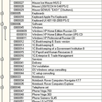
Fig. 437. Hierarchical detailed records
10.9.3. Displaying one item in multiple parent records
In the data composition system, you can output a single item in multiple parent records when you build a hierarchy.
Consider the example below.
Create two catalogs in the configuration: Children and Employees, and also the EmployeesChildren information register with the Child and ChildParent dimensions.
Create records in the Employees catalog: Mary Summers and John Summers. Create a record in the Children catalog: Tom Summers.
Suppose, there are records in the information register EmployeesChildren:
| Child | Parent |
|---|---|
| Tom Summers | John Summers |
| Tom Summers | Mary Summers |
Create a query for the Children data set to get a list of children:
SELECT
Children.Ref
FROM
Catalog.Children
AS ChildrenAlso create a query for the Hierarchy data set that will get hierarchical records:
SELECT
EmployeesChildren.Child AS Ref, EmployeesChildren.ChildParent AS Parent
FROM
InformationRegister.EmployeesChildren AS
EmployeesChildren
WHERE
EmployeesChildren.Child IN(&Ref)
UNION ALL
SELECT
Employees.Ref, NULL
FROM
Ref.Employees AS Employees
WHERE
Employees.Ref IN(&Ref)The first union of the query selects children's parents. The second part of the query selects employees because the hierarchical set must contain the hierarchical records themselves.
Describe the links between data sets.
Specify the Children data set as the link source and the Hierarchy data set as the destination. The source expression is the Ref field. The destination expression is the Ref field. Specify the Ref field as the link parameter. Specify that a list of parameters is possible.
Describe the hierarchical link. Link the Hierarchy data set to itself. The source field is Parent. The destination field is Ref. Specify the Ref field as the link parameter and allow parameter list use.
Note. IMPORTANT. The hierarchical data set field, to which the dataset is linked, must be named the same as the data set in the original data set. Otherwise, the system cannot get field attributes for the hierarchical set and get presentation for hierarchical values.
In the report settings, create a hierarchical grouping by the Ref field whose presentation is changed to Parent and run the report:
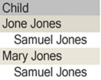
Fig. 438. Resulting table
As a result, the Tom Summers record is displayed in both groupings.
10.9.4. Condition IN HIERARCHY
Users can specify the IN HIERARCHY condition for the field. In this case, the user must be given records that are in the hierarchy of the specified reference.
If this condition is applied in the global filter, it will be in the query body as the IN HIERARCHY condition. If the condition is not used in the global filter, to process the condition, the data composition processor must have a data set that will contain references that meet the criteria.
The data set to build the hierarchy can be either explicitly described in the data composition schema or automatically generated by the template composer.
10.10. Using the data composition system for application development
In the process of application development, you can use the data composition system via 1C:Enterprise language tools according to the object model described above.
In addition, the data composition system can be involved in the visual design of reports. For example, after you create the Report configuration object, you can create a template for that report that contains a data composition schema. To do this, click the open button in the Main data composition schema input field.
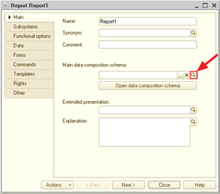
Fig. 439. Data composition schema creation
Clicking Open data composition schema will open the main data composition schema. If there is no schema, a new one is created and assigned as a main one.
This will open the Template Wizard, which will create a template that contains the data composition schema.
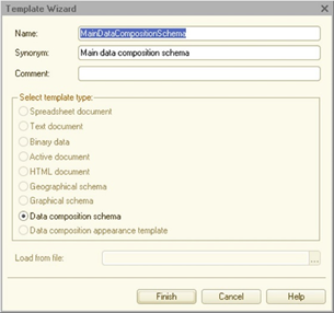
Fig. 440. Template wizard
When you click Done, the data composition schema wizard opens. You can use it to create a data composition schema or import an existing composition schema from an XML document.
After the data composition schema is created, the report is ready for use and can be started in 1C:Enterprise mode. When you run the report, the application automatically generates the report form and the settings form.
On the Forms tab, in addition to the main report form, you can specify:
- The report settings form that will appear when you execute the Setting... command, which is used to set custom settings, in 1C:Enterprise mode.
The report option editor form. To open it, click More actions – Change option... orAll actions – Change option... in the automatic report form. Advanced users can edit the current report option in this form.
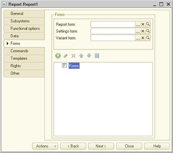
Fig. 441. Customizing report forms
If the forms automatically generated by the system for a data composition system-based report do not suit the end users of the application, the application developer can create their own forms. To do this, use the features of the report form wizard.
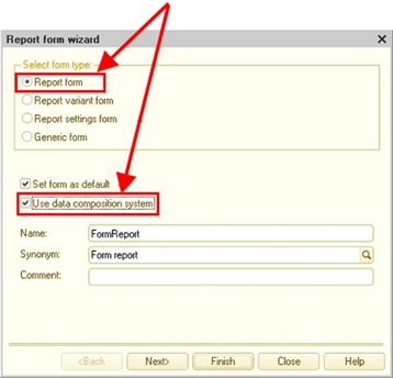
Fig. 442. Report form wizard
10.10.1. Input parameters
In the data composition schema, you can specify input parameters for data set fields, calculable fields, and parameters. These parameters describe how to enter values for fields in the filter and parameters. For example, in the Warehouse inventory report, you can enable Quick choice for the Products field. This way, by setting the item selection value, we will be able to use this feature. You can also specify a special choice form for the Warehouse field of the same report.
For more information on input parameters, see the online Help.
10.10.2. Using metadata object properties in reports
If the data composition schema uses the data set: query, the query fields from the metadata objects get information about the input parameters and some of the appearance options. Therefore, if you do not specify an input or output parameter in the data composition schema, the value will be automatically obtained from the corresponding metadata object.
The following input parameters are obtained from the metadata object:
-
Mask
-
Choice parameter links
-
Link by type
-
Link item by type
-
Choice form
-
Editing format
-
Quick choice
In addition, the following output parameters are obtained from the metadata object:
-
Format
-
Mark negatives
-
Multiline mode
10.10.3. Background report execution
When running the application, there might be situations when report generation takes a long time. It is desirable that the user can perform other operations with the application during such long-running report. This is achieved with the help of the background report execution feature, which uses the background job feature.
The automatically generated report form applies background report execution in the client/server mode. In the file mode, the report is generated directly. If background report execution is not required in the client/server mode, you can use the ComposeResult() report form extension method and specify direct report generation as its parameter.
Example:
ComposeResult(ResultCompositionMode.Directly);If you interactively change custom settings, interactively change or select a report option while the report is running in the background, the report will stop running and the spreadsheet document will be displayed in lighter colors.
If the report form is closed during background execution, the report execution will be automatically terminated even if the StandardProcessing parameter in the BeforeClose report form event handler is set to False. Report execution (and the corresponding background job) is stopped after the OnClose report form event handler is called.
When generating a report, various errors can occur. For example, a report can take up more RAM than the amount specified in the server limits. In this case, an exception is thrown. It is recommended that exceptions that can be thrown during report generation are displayed to the user instead of being ignored.
Background report execution can be accompanied by displaying the status window. The status window is generated if it is allowed (the AutoShowStateMode report form extension property) and if the report runs longer than 2 seconds (4 seconds in low-speed connection mode). To display the status of the report, the data composition system uses the StatePresentation property of the spreadsheet document field. If the report is generated within a specified time, the status is not displayed and the result is displayed immediately.
The client application will check the completion of report generation at a certain interval. In this case, the interval between each next check is 1.4 times longer than the previous one (but not longer than 20 seconds).
To control whether the report state can be displayed, use the AutoShowStateMode report form extension property. The property determines how a spreadsheet document that displays the report execution result will display the report status. By default (for example, for an auto-generated form), this property is set to Auto. This means that the status window will display information about report irrelevance and generation process.
If the infobase is connected to the collaboration system, the collaboration system is used to notify the client application about the report generation completion. This functionality is used simultaneously with the iterative process with increasing query intervals mentioned above. If the collaboration system is connected, the user will receive information on report completion earlier, which can visually reduce report generation time for reports whose generation takes a long time.
If a native background generation functionality is used for report generation instead of system background jobs, you can implement a similar functionality as follows:
-
A group non-displayed noncontext conversation is created in the infobase.
-
The current user is the only user added to this conversation.
-
The client application attaches a new message handler to this conversation.
-
The background job of report generation sends a message on report completion to the conversation.
-
The client application receives this message and performs all required actions on the client application's side (displays the report, notifies the user, and so on).
10.10.4. Saving series colors
In the data composition system, you can set up a chart in a report, so that reports displaying similar objects use the same colors for similar objects in a chart (for more information, see Using a single color for a series). For this purpose, there are two settings in the chart of the data composition system: Chart type.Save colors and Chart type.Color save key.
All primary operations are performed using the first property (Chart type.Save colors). It defines the way the platform ensures consistency of objects and chart colors:
-
For user. In this case, series object and color consistency data is stored in the system settings storage with the Common/ChartColors ID (the ValueAppearance object is used).
-
For current result. In this case, object and color consistency data is stored as part of a single report generation only without saving consistency data with respect to the object and color in between report generation. This can be useful if a report displays several charts using a single object set for the chart series. If this value is selected in settings, all series related to one and the same object will be displayed in different charts in one color. However, upon further generation, this color can be different.
-
For user key. In this case, object and color consistency data is stored in the system settings storage with a key generated using a value specified in Chart type.Color save key. The storage will store the ValueAppearance object. Using this parameter value, you can ensure that several reports use a single object and color correspondence in all charts. A full system storage key is generated through concatenation of Common/ChartColors/ and Chart type.Color save key. If any value is saved with respect to this key, data composition system behavior will be similar to setting the Chart type. Save colors parameter to Do not use.
-
Do not use. The data composition system defines series color each time in accordance with internal rules.
-
Auto. The Auto value interpretation depends on the following parameters:
-
If compatibility mode is Version 8.3.15 or earlier, and there are two or more series groupings, Auto is interpreted as Do not use.
-
If the Chart type. Color save key value is undefined, and compatibility mode is Version 8.3.15 or earlier, Auto is interpreted as Do not use.
-
If the Chart Kind. Color Save Key value is set, Auto is interpreted as For user key.
-
Otherwise, Auto is interpreted as For user.
-
For reports where numerous various series are expected to be displayed in a chart per a single configuration user, it is recommended that you set Chart Kind. Color Save Key to For current result. For reports where a report in various options displays data by small series groups, it is recommended that you set a color save key.
If when you generate a chart object and color consistency data is retrieved from the system settings storage, the data composition system re-writes ValueAppearance after chart generation is completed. Therefore, object - color consistency always remains up-to-date.
The client application form extension supports the Clear saved chart colors command for reports. It allows users to clear any existing object – color consistency. Only objects used in the current report are cleared in theChart type.Save colors and Chart type.Colors save key parameters. However, series colors defined in the process of report development remain valid. The said command is available only if the current report contains charts.
10.11. Features of using the data composition system
-
In the data composition system, names equal to the following keywords cannot be specified as a data path: CASE, WHEN, THEN, ELSE, END, IS, NOT, LIKE, ESCAPE, and DISTINCT.
-
If the standard period parameter contains an empty start date or end date, it is assumed that the nested StartDate and EndDate parameters are not set. That is, if the start date of the Period parameter contains an empty date, the Period.StartDate parameter is considered undefined. The same principle is applied to the Period.EndDate parameter and period end date. Correspondingly, the parameters in which the Period.StartDate and Period.EndDate parameters are used are considered unspecified.
-
The query is considered incorrect if it contains the DISTINCT keyword, and the ORDERBY clause specifies an expression missing from the dataset list.
-
Period fields cannot be grouped by attribute fields.
-
If the user does not have the right to interactively view the metadata object, the composition system considers all fields in the object table unavailable.
For example, suppose you use the following query as a data set:
SELECT
Doc.Ref.Date, Doc.Ref.Number, Doc.Products, Balances.Balance
FROM
Document.SalesInvoice.Content AS Doc
LEFT JOIN AccumulationRegister.ProductAccounting.Balances Balances
BY Doc.Products = Balances.ProductsIf the user does not have any interactive rights to the SalesInvoice table or SalesInvoice.Content, the Date, Number, and Products fields will be unavailable. If you do not have rights to the AccumulationRegister.ProductAccounting table, the Balance field will be unavailable. If you have no rights to any table, all fields will be unavailable.
-
Child fields of union type are available in custom settings if you have the View right for at least one table of union type and the field. Child fields become available for selection, can be included in filter, sorting, conditional appearance, and in other areas of user settings with presented available fields.
-
Upon data composition template generation, drilldown expressions, which contain fields that are unavailable by functional options, are removed from predefined templates.
-
The field of the hierarchical data set being linked to must have the same name as the field in the source data set. Otherwise, no attribute fields will be obtained from the hierarchical data set.
-
If a data set query in the selection list results in an expression that is the application of the PRESENTATION() function to an expression that is obtained in another field, the field where the presentation is obtained will be unavailable for use in the settings upon automatic filling of available fields.
-
When compiling data, an error will be thrown if grouping is performed by a calculated field and the grouping specifies the need to add in the period.
-
In grouping templates of the data composition system, autoindent is performed only for the upper left template cell.
-
When a batch query is used in the data composition system, fields that are not used in subsequent batch queries are removed from the dataset list and grouping fields. If a query that generates a temporary table does not contain any field, this query is removed from the batch query. Also, data sets that do not use any of the fields are excluded from the resulting template. To prevent such fields from being deleted, either use this field or select the Required checkbox as a data composition schema role.
-
If the temporary table fields that are created in the query of the data composition system are not used by subsequent requests from the batch query, and if the temporary table that you are creating is not in the required joins, the query that creates a temporary table is removed from the batch query of the data composition template.
For example, suppose you use the following query as a data set:
SELECT
Product
INTO
TemporaryTable
FROM AccumulationRegister.Sales
Group by Product
;
SELECT Warehouse, Product
FROM
AccumulationRegister.Balances LEFT JOIN TemporaryTable BY TrueIf the Product field is not in the data composition settings, the first batch query will not be deleted, because the TemporaryTable table is in the required join.
-
When displaying the data composition results in the collection of values, the fields of different groups referring to the same data composition field fall into one column of the collection.
-
When a data set of the data composition system is used in a query with automatic filling of available settings of the UNION or UNION ALL structure, as well as upon filtering a field attribute, filter is applied only to those parts of the union where this attribute exists. When you apply filter to a field, it is applied only in those parts where the field expression is not NULL.
-
When the list of available fields is generated, privileged mode of operation is considered in case of use from 1C:Enterprise language. If you want the contents of available fields to consider user access rights, but the composition result to contain all the data, it is recommended that you perform composition of the data composition template in regular mode and perform data composition in privileged mode.
-
During the calculation of data composition system expressions, the system is switched to safe mode (see Safe mode).
-
When using table fields derived from other fields in the data composition system query, it is recommended that you explicitly specify aliases for tables and its nested fields. Otherwise, you may have problems with the availability of fields when composing the data composition template.
-
If you want to apply filter by the DataVersion or PredefinedDataName attribute to some field, with a comparison type other than equal/not equal, filled/unfilled, greater than (or equal to)/less than (or equal to), in the list/not in the list, you need to ensure availability of this field for selection, not just its applicability in the filter.
-
If you need to set the value of the parameter required for correct operation of the data composition schema query, it is recommended that you set the parameter to Always when enabling availability of this parameter for the user.
Otherwise, if the option is disabled and the option is disabled due to unavailability by functional options or, directly, by the user of the report, an error will occur about an unknown value of the parameter when executing the report.
For example, the report uses the query:
SELECT
SalesInvoice.Date, SalesInvoice.Number, SalesInvoice.DocSum
FROM
Document.SalesInvoice AS
SalesInvoice
WHERE
SalesInvoice.Warehouse = &WarehouseIf the Warehouse parameter must be set by the user, remove the user's accessibility restriction and set the parameter use to Always.
If possible, the best solution would be to use the parameter in the {WHERE} data composition query section.
In this case, the application will automatically disable conditions whose parameters are disabled.
Example of a modified query:
SELECT
SalesInvoice.Date, SalesInvoice.Number, SalesInvoice.DocSum
FROM
Document.SalesInvoice AS
SalesInvoice
{WHERE
SalesInvoice.Warehouse = &Warehouse}- The source of available settings of the data composition system does not automatically make it possible to use the fields that have the password mode specified in the metadata object properties. This way, the field cannot be seen in the report or dynamic list.
If you perform template composition from 1C:Enterprise language, password-protected fields can be used if you pass the False value to the CheckFieldsAvailability parameter of the DataCompositionTemplateComposer.Execute() method.
Chapter 11. Accounting
Accounting in 1C:Enterprise is provided by the Charts of accounts and Accounting registers configuration objects. Since these objects are closely related, this chapter provides a general description of the capabilities provided by these objects.
The following sections will cover the configuration of the listed objects.
11.1. Overview
Designer tools allow you to set up accounting for multiple charts of accounts. Besides, you can build an arbitrary subaccount hierarchy of deep nesting for each chart of accounts. The accounting results are stored by 1C:Enterprise separately for each chart of accounts.
The chart of accounts can have flexible account numbering with digits and letters.
Analytical records can be maintained for any account or subaccount and include various analytics breakdowns. Analytical accounting objects can be the elements of 1C:Enterprise catalogs, documents, or arbitrary numbers, dates, and rows.
The configuration tools allow you to maintain an unlimited number of accounting types for each chart of accounts. A typical example of accounting types is quantitative and currency accounting.
The accounting type is enabled when you edit the chart of accounts. For each account, you can specify whether the account will have a different type of accounting.
Designer provides the means to set up accounting for several enterprises in one infobase. The summary information can be received both on the separate enterprise, and on the whole, on all enterprises. This feature will be useful for enterprises with consolidated balance.
11.2. Charts of accounts
Chart of accounts is one of the basic concepts in accounting. Chart of accounts is a set of synthetic accounts that groups data related to business activities of an enterprise. Data stored in such synthetic accounts provides the user with a complete picture of the state of the enterprise funds in monetary terms.
1C:Enterprise application provides flexible options for keeping the charts of accounts. Actually, the required accounting type is configured by setting up the chart of accounts.
Several charts of accounts. 1C:Enterprise can contain several charts of accounts and accounting for all chart of accounts can be performed simultaneously. 1C:Enterprise can contain several charts of accounts and accounting for all chart of accounts can be performed simultaneously.
For example, such "multi-track" accounting will obviously be needed for joint ventures that need to keep records at the same time on two or more accounting standards.
Subaccounts. Charts of accounts in 1C:Enterprise application support a multi-level "account – subaccounts" hierarchy. Each chart of accounts can include an unlimited number of top-level accounts. Each account can also have an unlimited number of subaccounts. Each subaccount, in turn, can have its own subaccounts, and so on. Number of subaccounts levels in 1C:Enterprise is unlimited.
You can set up an account code structure when you create a chart of accounts as a template that consists of an arbitrary sequence of characters. Technically, the account code structure does not affect the account hierarchy, but it is recommended to adhere to the code structure when creating the account structure.
Split account editing. It is known that mistakes in accounting are often caused by improper application of the approved chart of accounts. The most common situation is the lack of analytical accounting on accounts for which the expanded balance is to be obtained. Then the accounting that is correct in terms of the format gives wrong results. That is why, you might consider limiting the creativity of end users in setting up charts of accounts.
For this purpose, 1C:Enterprise application allows you to divide the process of editing the chart of accounts.
First, the editing of the charts of accounts can be performed in Designer by a specialist who performs the configuration of the 1C:Enterprise application.
New charts of accounts can be created in Designer. When you configure charts of accounts, you specify their main characteristics: length of account code and account name, the maximum amount of extra dimensions within one account (subaccount), and other. You can also enter required accounts and subaccounts (predefined accounts) in the chart of accounts and set up accounting types in accounts.
Second, when operating with 1C:Enterprise application, the end user can add their own accounts and subaccounts to the chart of accounts, but they will not be able to delete the predefined accounts and subaccounts created in Designer.
Storage of accounting totals. Accounting records are stored in the accounting registers according to the structure of the chart of accounts. The summary information can be viewed in the register forms and also extracted by means of the 1C:Enterprise language. For this purpose, the language has methods to receive balance and turnovers on accounts by any accounting type both on the whole account or subaccount and broken down by analytical accounting objects.
11.3. Analytical accounting
Information about enterprise assets that accumulates in accounts is often general. For example, in the "standard" chart of accounts, there is account 10 "Materials". It is used "...to summarize information on the number and changes of raw materials, materials, fuel, spare parts, packaging, and other valuables that belong to the company". Subaccounts can be opened for account 10 to account for different types of materials. But with this accounting organization, subaccounts will accumulate information on the total cost of materials of the same type, and account 10 will accumulate the cost of all materials.
To obtain detailed information on the availability of specific materials, you need to set up analytical accounting for materials. In this case, the total amounts on the subaccounts are broken down into smaller amounts, which are costs of specific materials.
In 1C:Enterprise application, analytical accounting is carried out by means of a special extra dimension tool.
"Extra dimension" concept. In 1C:Enterprise application, extra dimension is an analytical accounting object. "Extra dimension" can stand for any objects of analytical accounting: fixed assets, intangible assets, materials, companies, accountable persons, contracts, budgets. The type of extra dimension, in turn, is a set of the same-type objects of Analytical Accounting.
For example, the accounting of enterprise indebtedness to buyers and customers is necessarily conducted according to normative documents, separately for each buyer and customer. In 1C:Enterprise application, such list of buyers and customers (suppose that these are only companies) will be called "Company extra dimension type" and any company from this list will be called "extra dimension".
1C:Enterprise Designer allows you to create any number of extra dimension types in accordance with the requirements for analytical accounting completeness at the enterprise.
To describe properties of analytical accounting objects, you can use Chart of characteristic types objects.
Note. Attention! It is not recommended to use primitive types for the chart of characteristic types that is used as extra dimension types of the chart of accounts. This can significantly affect performance when recording the movements of the accounting register. We recommend that you use only reference types.
Managing analytical accounting. In 1C:Enterprise application, you can carry out analytical accounting on any account or subaccount. To do this, when you edit the chart of accounts, "attach" the necessary extra dimension type to the required account or subaccount. You can attach several types of different extra dimensions to an account or a subaccount (their maximum number is defined in the Maximum number of extra dimensions property) and carry out analytical accounting in any necessary breakdowns.
Information about business transactions in 1C:Enterprise application is entered as records of accounting registers. For each corresponding record account (if analytical accounting is specified for these accounts), specify analytical accounting objects.
For example, in manufacturing plants, you can apply extra dimension types to the production cost account: Cost types for accounting by cost types, Products for accounting by types of products (works or services), and Divisions for accounting by company divisions. Analytical information on costs can be obtained by any of these extra dimension types.
Besides, analytical accounting in 1C:Enterprise application allows you to keep accounting for the same dimension object in different breakdowns.
So, the same catalog can be assigned by different extra dimension types. For example, a company buys components from vendors and sells finished products to customers. In this case, in 1C:Enterprise application, the Companies catalog can be assigned by the Vendors extra dimension type and the Customers extra dimension type.
Extra dimension and subaccounts. Properties of charts of accounts in 1C:Enterprise application (in particular, a large number of nesting levels of subaccounts or a large subaccount code length) allow you to manage analytical accounting using subaccounts, not extra dimension. However, conducting analytical accounting on subaccounts and using extra dimension provide significantly different capabilities.
Subaccounts are a hierarchical structure subordinate to a specific synthetic account. For example, to account for the customers' debt to the enterprise on a synthetic account of accounts receivable (in the standard chart of account, it is account 62), you can open a separate subaccount for each customer and account for debts on this subaccount. This scheme will provide information on both the amount of the enterprise debt to a particular customer and the total amount owed to all customers. It would be obtained by summing up the information on the debt amounts from all subaccounts.
However, if any of the customer companies becomes a vendor as well, you will also need to configure accounts receivable with the company as a vendor. If you conduct analytical accounting on subaccounts for a new vendor, you will need to open a new subaccount in the accounts payable account (account 60). Now, if you keep accounting on this subaccount, you can get information about AR/AP accounting with a company as a vendor.
However, to get data about a general state of AR/AP accounting with a company, consolidate the information on AR/AP accounting with this company from two accounts. You need to remember which subaccount on the account of accounts receivable and which subaccount on the account of accounts payable match a particular company to be able to obtain information on the AR/AP accounting status from these subaccounts and process it.
When you use extra dimension, the same extra dimension list, such as Companies, is attached to all accounts (subaccounts) on which you want to carry out analytical accounting for companies. Accounting with a specific company as a vendor is carried out on the corresponding synthetic account. If the company becomes a customer as well, you do not need to create a new position in the company list as it is already included in this list as a vendor. Information for one company from two synthetic accounts is mostly consolidated by 1C:Enterprise application automatically. Similarly, you can consolidate data from any accounts that have been used to record transactions involving a particular company.
Multi-level analytics. Multi-level analytics allows to get accounting results with varying degrees of detail. If extra dimension is used to conduct the analytical accounting, assign the chart of characteristic types as extra dimension types to implement multi-level analytics (see Charts of characteristic types). Using Charts of characteristic types objects allows to keep records with the required degree of detail. The limit on the number of nesting levels imposes the use of a characteristic value type (for example, any hierarchical reference can be selected as a value type, and a union type may be used).
When conducting analytical accounting using subaccounts, multi-level analytical accounting is implemented using subaccounts of different levels.
11.4. Accounting types
As mentioned above, 1C:Enterprise application allows you to maintain an unlimited number of accounting types. Examples of accounting types are quantitative and currency accounting.
Designer provides an opportunity to set up an unlimited number of different accounts. Accounting types are defined by subordinate objects of the Accounting flag type of the Chart of accounts object.
11.5. Accounting register records and record sets
The basic accounting concept is the concept of business transactions. A transaction is any economic activity that is capable of causing a change in the state of enterprise assets.
Documents are used to enter information about business transactions in 1C:Enterprise application. A document allows you to enter in the application information on a business transaction, to fix the date and time of transactions, the amount and contents of the transaction.
Transaction credentials are automatically generated based on the document (data object of the Document type) and recorded in accounting registers. The order of such generation is defined in Designer by means of 1C:Enterprise language. When you record data for a transaction, you can describe how to fill transaction details with different information from the document that generated the transaction.
In 1C:Enterprise, accounting for a business transaction is always associated with the document that generated it. If the document needs to be edited, the transaction data will be regenerated when you post the document. When you delete the document, the business transaction data will also be deleted.
Each business transaction consists of an arbitrary number of entries. In 1C:Enterprise application, each entry corresponds to a record in the accounting register and an accounting register record set is similar to a business transaction. For more information on how to use entries, see Accounting registers.
11.6. Maintaining consolidated accounting
In accordance with the current legislation, companies having business units including those allocated to a separate balance (branches, representative offices), prepare reporting considering the activity of all business units. Such companies need to be able to carry out accounting of all business units and receive consolidated reports in one infobase. While preparing accounting reports, such companies might also consider submitting the main indicators of business unit activities separately to avoid unnecessary questions from tax authorities.
Tools for accounting in 1C:Enterprise application allow you to carry out accounting for several enterprises (or business units of one enterprise) simultaneously in one infobase. Such issues are solved by generating dimensions of the accounting register that will contain a reference to a business unit.
The information that is entered in this dimension when operating with 1C:Enterprise application is used to indicate separate storage of accounting totals. 1C:Enterprise application automatically configures a system for storing accounting totals dividing them by a value of the specified dimension. With the help of 1C:Enterprise language the information from the totals can be extracted both for the particular enterprise and in general for all enterprises.
11.7. Creating charts of accounts
To maintain charts of accounts in 1C:Enterprise application, use the Chart of accounts configuration objects. Data objects of this type are accounts that represent accounting registers used to group funds when operating with 1C:Enterprise application. Designer allows you to create almost unlimited number of charts of accounts. All charts of accounts created in Designer can be used at the same time.
Charts of accounts in 1C:Enterprise application support a multi-level account – subaccounts hierarchy.
11.7.1. Properties of charts of accounts
You can edit properties of the Chart of accounts objects and create subordinate objects in the editing window and in the property palette. This section will describe the specific properties of the configuration object of the Chart of accounts type.
Code mask. It is used to describe the code structure of accounts and subaccounts. The following special characters are valid in the mask string:
-
!. Any entered character will be converted to uppercase.
-
- Any numerical character is allowed.
-
#. Any numerical character, - (minus sign), + (plus sign), or a space is allowed.
-
N. Any alphanumeric characters (letters or digits) are allowed.
-
U. Any alphanumeric characters (letters or digits) are allowed and all entered characters will be converted to uppercase.
-
X. Any character is allowed.
-
@. Any alphanumeric characters (letters or digits) in uppercase or a space are allowed.
-
^. This character cannot be entered by the user manually, it must be specified using the language.
-
h. Characters used in hexadecimal notation are allowed.
To use one of the special characters in a mask, put a backslash "/" before it.
If the code mask contains points or does not contain commas, all points will be automatically replaced with commas when you enter an account code.
Autoorder by code. If the property is set, the ordering by the Order field will be used instead of ordering by account code.
Order length. If the length is greater than zero, the Order field is the default for ordering the chart of accounts.
Note. Note. The maximum length of the Code length, Name length, and Order length attributes is 628.
Attributes. Specify different account or subaccount details, for example, the name of account 10 is "Materials".
Accounting flags. They are defined by a list of accounting types. Typical examples of accounting types are foreign currency and quantitative accounting. Configuration developers can create as many accounting types as they need to implement a specific task.
Tables. Tables are not used for "standard" charts of accounts. An example of how subordinate objects of the Table type are used can be simultaneous accounting of data in different charts of accounts carried out to ensure the expanded correspondence of accounts of different charts of accounts.
Maximum extra dimensions. Defines the maximum number of extra dimensions (up to 50) used to organize analytical accounting.
Extra dimension types. Specifies an object of the Chart of characteristic types type (see Charts of characteristic types).
Extra dimension accounting flags. Creates a list of extra dimension accounting flags. When you set up analytical accounting for accounts, these flags allow you to indicate whether a particular extra dimension type is used to generate predefined accounts.
11.7.2. Managing different accounting types
You can set up an arbitrary number of accounting types for each chart of accounts.
For each account or subaccount, when creating one, specify whether each accounting type defined for this chart of accounts is used.
11.7.3. Creating a list of accounts (predefined accounts)
Accounting records as data objects are created in Designer.
To create a list of predefined accounts in the Properties palette of an object of the Chart of accounts type, in the Predefined property, click Open. This displays the accounts list window.
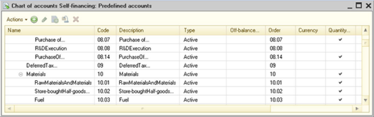
Fig. 443. Chart of accounts
The accounts list is maintained by the Actions menu commands.
Account information is generated in the Account editing window.
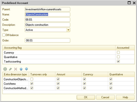
Fig. 444. Editing a predefined account
In the Type attribute, specify an account type: Assets, Liabilities, or Assets/Liabilities.
For off-balance accounts, select the Off-Balance checkbox. The totals of the off-balance sheet accounts are not accounted for in the balance.
The Order field is intended for the arbitrary ordering of accounts. To set a field length, use the Order length property of the chart of accounts. If the field length is greater than zero, this field is the default for ordering the chart of accounts. If the chart of accounts is set to Autoorder by code, ordering by the Order field will be used instead of ordering by account code or name. To fill the Order field by account code, use the GetCodeOrder() method, which generates an account order string considering the account code mask.
The first list shows accounting flags defined for the Chart of accounts object. To indicate that the account you are editing belongs to a specific accounting type, select the checkbox in the Account column.
The following parameters are specified for each lower list entry. One of the predefined types of characteristics is selected in the Extra dimension type column. If subordinate objects are defined for this chart of accounts in the Extra dimension accounting flags branch, columns by the number of these objects are added to the list. For each extra dimension type, select a checkbox if you want to maintain an analytical accounting for this extra dimension. Note that if the account as a whole is not accounted for by any accounting flag, the corresponding accounting flag for the extra dimension must always be selected, otherwise the accounting flag for the extra dimension must be cleared according to the accounting needs.
In 1C:Enterprise mode, the end user can add their own accounts and sub-accounts to the chart of accounts and edit the properties of accounts (including those created in Designer). The deletion mark and deletion of accounts and subaccounts (including those created in Designer) is controlled by access rights (see Access rights description). For more information on predefined items, see Predefined data.
11.8. Accounting registers
To record information about business transactions in accounting, 1C:Enterprise application provides accounting registers described in the Accounting registers configuration tree branch.
11.8.1. Accounting register properties
An accounting register looks like an accumulation register. When you edit it, develop the register structure: create register dimension sets, resources, and attributes. If necessary, create screen and print forms to view register records.
The distinguishing feature of the accounting register is its connection with the chart of accounts and support of double entry mechanism. Each register entry contains the required Account Dr (debit account) and Account Cr (credit account) attributes for registers supporting the correspondence and the Account attribute for registers that do not support it.
The Allow split of totals property allows you to use the total separator, which provides a higher parallelism when writing to the register.
Note. Note. Values of the UUID, BinaryData types and strings of unlimited length cannot be used as accumulation register dimension types.
The Period adjustment length property allows you to specify whether period adjustment is used for this register and how many intervals the period adjustment will include if it is enabled. This property indicates how many equal intervals one second will be split to:
-
If the property is set to 0, period adjustment is disabled.
-
If the property is set to a non-zero value, period adjustment is enabled. In this case, each second can be broken down by 10 (the property value is 1), 100 (the property value is 2), or 1,000 intervals (the property value is equal to 3).
When specifying a register record in any of the period adjustments, such register record will not be accounted for in the closing balance of one period but will be accounted for in the opening balance of the next (adjacent) period without distorting turnovers of each of the two adjacent periods. At the same time, register records made in period adjustments will be recorded in turnovers if the analysis period completely covers the period when the register records were made specifying a period adjustment. The period adjustment is logically located between the period and the recorder.
11.8.2. Accounting register records
In order for the information entered by a document to make change in the accounting results, the document must generate accounting register records.
Records of a particular document make up a group (by the document-recorder) and at any changes in attributes of the document or in the records themselves are always "held" together. The order of generation of records is also determined by 1C:Enterprise language.
The structure of the record is built by the 1C:Enterprise application dynamically, depending on the setup of the various accounting elements that were executed when editing the chart of accounts. For example, a record can contain details for entering corresponding accounts, amounts, Analytical Accounting objects, quantity, currency type, and currency amount.
In addition to these attributes, Designer can write the necessary number of additional attributes to reflect any other necessary information. For example, it may be an attribute to store a comment record.
When operating with 1C:Enterprise application, the user can "disable" records and then re-enable them. "Disconnected" records do not affect the accounting totals, that is, balance and turnovers on accounts. You can disable and enable records using the Active property.
This feature is convenient to account for planned business transactions, which should happen in the future. By disabling records of such transaction, you cannot change actual accounting totals. At the moment when a business transaction is performed, you can just set activity for these records.
When you enter records, 1C:Enterprise application performs various predefined actions that facilitate and accelerate the user's operation with the application. For example, if an analysis account is specified for a corresponding account, the application will automatically open the required list of analytical accounting objects (extra dimension) to allow the user to select the desired object. You can customize most aspects in 1C:Enterprise application behavior by editing properties of accounting register records.
Chapter 12. Periodic calculations
12.1. General information
Periodic calculations are calculations carried out at certain intervals, closely related to each other according to certain rules and mutually influencing each other within a certain period.
Periodic calculation mechanisms allow you to adjust the order and relationship of calculations and to organize the accounting of their results.
The most typical example of the use of periodic calculations is the payroll calculation, in which calculations of accruals and deductions are made. Calculations are usually performed with monthly periodicity, and results of calculations of one kind can depend on availability and results of calculations of other kind.
Accounting in 1C:Enterprise is provided by the Charts of calculation types and Calculation registers configuration objects. Since these objects are closely related, this chapter provides a general description of the capabilities provided by these objects.
The following sections will cover the configuration of the listed objects.
12.2. Basic concepts
Period. The concept of the period is important for calculations. Typically, the period is described by Start Date and End Date. If periodicity is defined for a calculation (see the description below), you can specify any date to describe the (activity, registration) period of this calculation. This date calculates a period start date and this date will describe the period. Such period definition process allows you to optimize the execution of queries that require to select records related to the specified period.
Periodicity of calculations. Specifies a period in which calculations considered by this register will (can) be performed. Set in the Periodicity calculation register property. The property value (if the register is periodic) determines the validity period of the calculation register record. For example, if the register periodicity is Month, a document date (for example, a calculation for November 2008) is selected as the validity period when generating a register record. By this date, the application determines the validity period at the beginning of 11/01/2008.
Registration period. A period start date specified during the calculation registration (calculated by the date of the document recorder). For example, in June 2008 the salary is accrued for May 2008 (calculations with the Month periodicity). May 2008 is the validity period (date 05/01/2008 is recorded in the database) and June 2008 is the registration period (date 06/01/2008 is recorded in the database).
Validity period. A period start date determined according to the Periodicity property value. For example, the document indicates that the calculation is made in May 2008. For the Periodicity property value of the Month register, the validity period is determined by date 05/01/2008. For the Quarter value, the validity period is determined by date 04/01/2008.
Calculation validity period. Specifies a period in which the calculation is performed. The period is determined by the period start date and end date. For example, the validity period of a sick-list record for May 2008 is 05/01/2008. The calculation validity period is determined by the start date (for example, 05/06/2008) and the end date (for example, 05/15/2008).
Overriding mechanism or competition for the calculation validity period. Displays the relationship between calculation types for the calculation validity period. The competition arises as several calculation types cannot be executed simultaneously. Select a calculation that will be performed in this period. Overriding mechanism is set in the description to a particular calculation type. This setup is performed in the Overriding (calculation types) section. For example, the Payment by salary calculation cannot be applied simultaneously with the Payment on the sick-list calculation. The sick-list calculation overrides the salary calculation. It means that salary is not accrued for the period in which the sick-list is applied. For details on overriding, see Overriding mechanism.
True effective period. If the calculation is not overridden by other calculations, the true effective period coincides with the validity period. If there are overriding calculation types, the true effective period is defined as a set of non-intersecting periods where this calculation is not overridden. In fig. 445, you can see graphic presentation of the true effective period, where the Salary calculation is overridden by the Sick-List calculation.
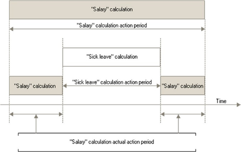
Fig. 445. Overriding mechanism
The true effective period represents secondary data, that is, the result of calculations performed by the application. The true effective period is recalculated when recording any set, including the blank one (posting cancellation).
Note. WARNING. The result of calculations does not depend on the sequence of data input (registration).
Base period. Defines a period in which the results of calculations that are used (base) for this calculation will be selected. For example, when calculating a bonus for May 2008, the results of accruals performed by certain calculation types for a certain period (for example, Salary, Extra pay, or Vacation) are considered. This period will be base for the bonus calculation. You can set up the relationship between calculation types for the base period in the description to a particular calculation type in the Baseline (calculation types) section.
12.3. Charts of calculation types
Configuration objects of this type are used to create calculation types that are used in calculation registers.
A reference to the calculation type is one of the main calculation register record properties. It allows you to give qualitative differences to different calculation register records.
You can edit properties of the Chart of calculation types objects and create subordinate objects in the editing window and the property palette. Below, you can read about common and unique properties of the chart of calculation types.
12.3.1. Specifying calculation properties
Depends on base. If the Depends on base property differs from the Does not depend value, the calculation types of the chart of calculation types can specify a list of baseline calculation types. Baseline calculation types are determined by the Base charts of calculation types property.
Base charts of calculation types. Specifies a list of charts of calculation types whose calculation types can be included in the list of baseline calculation types. This list of baseline calculation types is used by the calculation register when the base receipt mechanism operates.
Uses base period. If the property is set, this chart of calculation types can be assigned to the calculation register with the validity period. In this case, a list of overriding calculation types can be specified for each calculation type. The list of overriding calculation types determines how the overriding mechanism of the respective calculation register operates (see Overriding mechanism).
Properties specified in this category determine attributes that are included in the list when creating calculation type forms. If the Depends on base property is set to Depends on the validity (registration) period, you can place a table field on the form to select calculations types that are baseline for the editable calculation. If the Uses base period property is set, you can place a table field on the form to select calculations types that are overriding for the editable calculation type.
12.3.2. Predefined calculation types
The chart of calculation types features predefined calculation types that were created during setup. In 1C:Enterprise mode, the user can also edit such calculation types. The deletion mark and deletion of calculation types (including those created in Designer) is controlled by access rights (see Access rights description). For more information on predefined items, see Predefined data.
To edit the list of predefined calculation types, in the properties palette, go to the Other tab and click Predefined. The screen displays a list of predefined calculation types of this chart of calculation types (see example fig. 446).
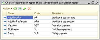
Fig. 446. Predefined charts of calculation types
Use the Actions menu to manage the list of predefined calculation types.
The structure of attributes (basic and leading) of predefined calculation types depends on the set properties of this object of the chart of calculation types placed in Calculation category.
Each predefined calculation type is edited in a modal window. The basic properties of the calculation type are entered on the Main tab.
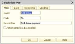
Fig. 447. Editing the chart of calculation types
If the Depends on base property is set to Depends on the validity (registration) period, the form contains the Baseline tab. It specifies calculation types that are baseline for this calculation type and determines how the base of the respective calculation register is obtained.
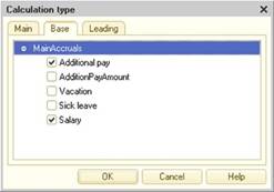
Fig. 448. Base accruals of calculation type
In the example (see fig. 448), baseline calculation types for the Sick-list calculation type are Salary and Extra pay.
If the Uses base period property is set, the form contains the Overriding tab. It specifies calculation types that override this calculation type by the validity period and set up the overriding mechanism of the respective calculation register.
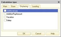
Fig. 449. Overriding calculation types
From the calculations enumerated in the list (see fig. 449), specify an overriding calculation type. In the example above, the Sick-list calculation type has no overriding calculation type. However, when describing the Salary calculation, select Sick-list.
On the Leading tab, specify calculation types that determine the operation of the recalculation mechanism for the respective calculation register, that is, the one which this chart of calculation types is assigned to.
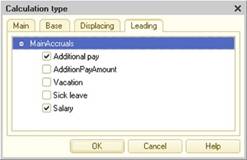
Fig. 450. Leading calculation types
Besides predefined calculation types, you can create your own calculation types and set the desired properties in 1C:Enterprise mode. To do it, in Designer, create an item form where you want to place table fields to specify baseline, leading, and overriding calculation types depending on the set properties of this chart of calculation types.
12.4. Calculation registers
12.4.1. General information
Calculation register is a configuration object that allows you to account for the results of calculations performed by calculations specified in the chart of calculation types. Calculation registers allow you to register accruals in favor of individuals (salaries, payment of sick-lists, payment of vacation days, and so on).
Calculation register accounts can affect the state of other register records. There are two ways calculation register accounts may have mutual influence on each other: competition for the period of validity and dependence on the base period. Let us explain these ways of mutual influence of accounts on examples.
12.4.1.1. Overriding mechanism
To explain the competition for the validity period, consider an example where an individual is accrued a payment on the main remuneration form (salary) and the vacation payment. The account that corresponds to the salary payment and the account that corresponds to the vacation payment may not correspond to the same time interval. It means that time intervals for which such accruals are made cannot overlap. In the calculation register, this behavior of accounts (register records) is implemented by using the concept of the register record validity period. Each calculation register record has an actual validity period, which is set in the general case by a collection of several time intervals.
For example, if the validity period of a vacation record is from 03/03/2008 till 03/13/2008, the actual validity period of the corresponding salary accrual record may consist of two periods: from 03/01/2008 till 03/02/2008 and from 03/14/2008 till 03/20/2008.
The competition for the validity period is supported by the overriding mechanism of the calculation register. Its operation depends on overriding calculation types, validity period dates, and so on.
12.4.1.2. Recalculations mechanism
To explain the dependence of accounts on the base validity period, consider an example where an individual is accrued a salary payment and a payment on average earnings that depends on the salary. If the state of salary payment accounts is changed in the register in a certain period (for example, accounts are deleted, changed or new accounts are created), you need to revise the results of accounts with payment on the average earnings if such records are available for the relevant period. To implement such mutual influence of the calculation register accounts, the concept of the base period of register record is introduced. So, if an account corresponding to the payment on average earnings has a base period from 01/01/2008 to 03/31/2008 (that is, it uses average earnings for three months), any changes in salary accounts for this period will require to revise the account with the payment on average earnings.
12.4.2. Editing calculation registers
The Calculation registers branch of the configuration tree is used to operate with calculation registers.
When editing a calculation register, you define a chart of calculation types, regulate the validity period, base period, and periodicity, and also develop the register structure by creating sets of dimensions, resources, and attributes. If required, you can create screen forms and print forms to view register records.
Note. Note. Values of the UUID, BinaryData types and strings of unlimited length cannot be used as calculation register dimension types.
This section describes unique properties of the calculation register that are different from the general object properties.
You can edit properties of the Calculation register type objects and create subordinate objects in the editing window.
Chart of calculation types. The main register characteristic. For more information, see Charts of calculation types. You can specify only one chart of calculation types for the calculation register.
Validity period. If the property is set, the mutual influence of register records becomes competing. An example of competing register records can be payroll and sick leave as a person cannot work and be on a sick-list at the same time, that is, they cannot receive both salary and sick leave. Such calculations are mutually exclusive in time, and the application must ensure that entering one of them will result in the exclusion of the other.
The calculation register with validity period support has a limit on the number of records with the same dimension values, registration period and calculation type.
When calculating the actual validity period that occurs every time a register record set is recorded, a low memory error might occur if a large number of identical records are involved in the actual validity period calculation. In fact, this means that there is a limit for the number of records in the same time interval. For example, the same employee has been repeatedly accrued a salary payment for the same period.
The limit value depends on different conditions, such as used DBMS, technical characteristics of the computer, and so on. However, this limit does not take effect in practice.
Schedule. The property is available if the Validity period property is set. The property is a reference to an information register that describes a temporary schema of source data involved in the calculation. The schedule should be specified for calculations that depend on the source data distributed within the period of validity of a certain rule. For example, this can be a schedule for the company's operating time broken down by day, lecture hours broken down by hour, and so on.
Schedule value. The property is available if the Validity period property is set. The property selects an information register resource defined in the Schedule property.
For example, the CompanyOperatingSchedule information register is specified as a schedule. This register has the Workday (the Boolean type) and WorkingHours (the Number type) attributes. The first attribute indicates whether a date is a workday. The second attribute indicates the number of working hours in a workday. If you select the Workday attribute, the application will analyze during the calculation whether a particular day of the calculation period is a workday, that is, whether the payroll must be calculated for the specified day). If you select the WorkingHours attribute, the application will select the number of working hours during the calculation. Based on this value, the specified calculation will be performed. The distribution is set in 1C:Enterprise mode (manually or by means of 1C:Enterprise language).
Schedule date. The property is available if the Validity period property is set. The property selects an information register dimension that is defined in the Schedule property and has the Date type. Based on the property value, the dimension is linked to values of the information register resource specified in the Schedule value property.
Base period. If the property is set, the related mutual influence of register records is specified. An example of related register records is the dependence of calculating the accrual amounts by the average amount of the accrual amounts in the base period.
Periodicity. Determines a period with which register records are recorded and within which register records can affect each other (for registers that support the validity period).
Recalculations. Subordinate register objects that allow you to define rules of mutual influence of register records. In the Relationship group of the object property palette, the Dimension register property specifies the main dimension of the current register to recalculate when changing data of leading registers specified in the Data property of leading registers. For example, recalculation of the deduction amount for an individual will be formed at the changes of accruals (salary, bonuses).
If the Base period property is set, recalculation data will be generated automatically. If the property is not set, recalculation data must be generated manually by the user. When designing the application, developers should create a special form to enter recalculations and a tool to execute them.
Chapter 13. Business processes and tasks
13.1. Basic concepts
Business processes in 1C:Enterprise are intended to combine individual operations into chains of interrelated actions that lead to accomplishment of specific goals. For example, issuing an invoice, accepting a cash payment, and shipping goods from a warehouse can be combined into a Product sale for cash.
Business processes in the 1C:Enterprise application allow you to formalize processing procedures of the events arising in activity of the organization, and to ensure the participation of performers in them.
Using business processes in applications allows you to increase their efficiency, to improve the final result, and to get new capabilities.
Business processes provide an opportunity to move to process management and qualitatively improve the company's operations through reengineering and automation of business processes.
The greatest effect is the automation of key business processes that start and end in an external environment.
Such chains of interrelated operations within a business process are presented in the business process flowchart. A flowchart describes the logic of the business process and its entire lifecycle, from start to finish, as a sequence of route points.
The chain of interrelated actions will be called a business process movement.
A route point reflects a stage in the lifecycle of a business process, normally involving the completion of a single automatic or manual operation.
Tasks in 1C:Enterprise allow you to keep a record of jobs sorted by a performer and record the progress of business processes through the flowchart. In addition to business processes, tasks can be created by other infobase objects or directly by users.
13.2. General part
The mechanism of business processes in 1C:Enterprise is provided at once by several configuration objects:
-
Business processes
-
Tasks
-
Information register
-
Session parameter
As a rule, the types of task addressing attributes and information register dimensions have a reference type (for example, CatalogRef, so more catalogs are added to the four types listed above).
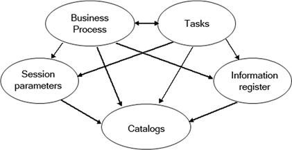
Fig. 451. Business process schema
The main objects, which are business processes and tasks, interact with each other (for example, the business process creates tasks, and the task in progress leads to its advancement on the route).
Auxiliary objects, which are session parameters, an information register, and catalogs, do not use each other or basic objects.
When creating a business process route map, catalogs with predefined data (roles, divisions, and so on) are used to set their values to address route points. Business processes create tasks when switching to route points and use Addressing (information register, see below) to process group points.
Tasks inform business processes about their performance, which causes them to move further along the route. They use the information register to filter the tasks for the current performer according to the set session parameter.
13.3. Routing
Business processes in 1C:Enterprise allow the following types of routing:
-
Strict. Business process has a strict flowchart, which does not include conditional and parallel transitions, with hard-coded destinations for each route point. This type does not allow free or conditional routing.
-
Free. The recipients of the business process flowchart point are not set and are determined programmatically or interactively during the business process lifecycle.
-
Conditional. The flowchart includes checking conditions and switching by the respective branches. Switches can be either binary (condition) or multiple (option).
-
Parallel. The flowchart provides for the division of the business process into parallel branches with the option of further merging (waiting). The advancement of the business process on each of the parallel branches takes place independently as the respective tasks are completed.
Typically, all these types of routing are found in real business process flowcharts.
13.4. Addressing system
Addressing system is the key concept in the mechanism of business processes and tasks in 1C:Enterprise. The main purpose of the addressing system is to provide an opportunity not only for personal, but also for role-based addressing of tasks to business process participants.
Role addressing (role-based routing) is a set of rules and agreements fixed in the settings of metadata objects, which allows you to determine the final addressee (performer), based on his/her assigned roles, affiliation with a division, as well as other addressing attribute.
Task addressing attributes define the dimension of address space in the context of an automated subject area and are used to determine the assignment of tasks to specific performers.
The definition of a specific performer is accomplished by using the following task properties: Addressing, Main addressing attribute, and Current performer.
The process of determining the main addressing attributes from other addressing attributes is called dereferencing.
Addressing is an information register that stores current information about the compliance of performers (the main addressing attribute) to structural units, workgroups, functions, and so on, that is, all other task addressing attributes.
One of the task addressing attributes is the main one and it means a certain employee, that is, a task performer.
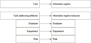
Fig. 452. Addressing scheme
Let us explain the operation of the addressing system in the example.
Assume that there is an information register that consists of two dimensions: a role and an employee. This information register contains the following entries.
| Role | Employee |
|---|---|
| Cashier | Smith |
| Manager | Collins |
Assume that there is a business process (for example, Accept cash payment) where in one of the points the Cashier role is set in addressing properties. When a business process moves to this point, one task will be formed.
| Task property | Value |
|---|---|
| Description | Accept cash payment |
| Role | Cashier |
| Employee | - |
When the employee Smith looks through the list of tasks for himself, the addressing system will show him this task as there is an entry in the information register that the Cashier role is set for Smith. The employee Collins will not see this task.
Here is an approximate sequence of actions to create two different business processes:
-
We will assume that a 3-dimensional addressing system is selected: Employee, Role, Division.
-
Let's create handbooks for each of the planned addressing dimensions (Employees, Roles, Divisions) and fill them with the predefined values:
| Employees | Roles | Divisions |
|---|---|---|
| Smith | Cashier | Accounting |
| Collins | Manager | Sales department |
| Johnson | Department manager | Warehouse |
| Storekeeper |
- Create an information register and add dimensions to it, one for each of the previously created catalogs. The dimension type should be set as a reference to the corresponding catalog:
| Dimension | Type |
|---|---|
| Employee | CatalogRef.Employees |
| Role | CatalogRef.Role |
| Division | CatalogRef.Divisions |
-
Create a session parameter CurrentPerformer and set it to the CatalogRef.Employees type.
-
Initialize the session parameter at application startup:
Procedure SessionParametersSetting(RequiredParameters)
User = Catalogs.Employees.FindByDescription(UserName());
SessionParameters.CurrentPerformer
= User;
EndProcedure-
Create a task.
-
Set the previously created information register to the Addressing task property.
-
Add the addressing attributes to the task similarly to the dimensions of information register:
-
Employee,
-
Role,
-
Division.
- Set the type for the created task addressing attributes as a reference to the corresponding catalog and set a reference to the information register dimension in the Addressing attributes property.
| Addressing attribute | Type | Addressing dimension |
|---|---|---|
| Employee | CatalogRef. Employees | Employee |
| Role | CatalogRef. Role | Role |
| Division | CatalogRef. Divisions | Division |
-
Select the Employee attribute as the main addressing attribute, setting it in the corresponding task property.
-
Create the first business process and set a link to the task created earlier (the Task property).
Let us design a business process flowchart, setting the necessary addressing attributes for the route points, selecting them from the predefined data of the corresponding catalogs.
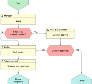
Fig. 453. Business process flowchart
-
Create the first business process and set a link to the same task.
-
Let us design a flowchart of the created business process. And so on.
In the future, we will use this example to comment on the key features of business processes in 1C:Enterprise.
Let's consider in more detail a few key features of the mechanism of business processes.
13.5. Starting business processes
The business process starts when you call the Start() method or click Start and close on the object form.
The following code fragment shows the programmatic creation, writing and start of a business process.
BP = BusinessProcesses.Agreement.CreateBusinessProcess();
BP.Date = CurrentDate();
BP.Write();
BP.Start();The following sequence of actions is performed at start.
| No. | Internal functionality | Handlers in 1C:Enterprise language |
|---|---|---|
| 1 | Call the BeforeStart handler of the start point | |
| 2 | Move along the flowchart to an activity | |
| 3 | Generate tasks (see Generating tasks) |
Business process can be written, but not started. This can be useful if the creation of a business process and its start are separated in time. For example, when a business process starts when a certain event occurs.
13.6. Completing tasks
When the ExecuteTask() method is called, the execution check is performed, after which the task is marked as completed and the business process is notified of the fact. If all the necessary conditions are met, the business process moves to the next route point.
| No. | Internal functionality | Handlers in 1C:Enterprise language |
|---|---|---|
| 1 | Start the transaction | |
| 2 | Call the BeforeExecute handler of the task | |
| 3 | Call the BeforeExecute handler of the respective route point | |
| 4 | Set the Complete task property to True | |
| 5 | Call the OnExecute handler of the task | |
| 6 | Write the task object | |
| 7 | Call the OnExecute handler of the respective route point | |
| 8 | Move a business process to the next route point | |
| 9 | Generate tasks at the new route point (see Generating tasks) | |
| 10 | End the transaction |
13.7. Separation and merger
A separation point is used to divide a business process into several parallel (simultaneously and independently) executable branches. The separation point has one entry and an unlimited number of exits.
A merge point is used to synchronize previously separated branches. The business process will not be executed beyond the merge point until all branches in it have been completed. Thus, the merge point is the stage of the business process where all the tasks must be completed on previously separated branches.
Nested separation and merging are permitted. In this case, each merge point will synchronize only the branches of its own separation point.
Note. Important. Separation may be also completed without merging. In this case, the business process will have several parallel branches before it is completed.
Merging without separation is not allowed, and the following message is generated when the flowchart is checked: Not all the lines at the merge point come out of the separation point.
13.8. Manual control
Business process completion and task execution flags can be set manually, bypassing the business process feature, but this must be done with a full understanding of all the possible consequences.
13.8.1. Business process completion flag
If the completion flag is set, the business process will be considered complete, even though the tasks associated with it are not yet completed. And when these tasks are completed, the completed business process will no longer move further along the route.
The completion flag can be set to a business process that has not been started. In this case, its start will no longer be possible.
If the completion flag is manually removed from the completed business process, then the tasks associated with it will still remain completed. Thus, the business process will not be completed, but there will not be any uncompleted task in it. It is impossible to restart such business process, since 1C:Enterprise will consider it to have been started (there is one or more tasks in it). Therefore, when manually removing the completion flag, the completion flags of the necessary tasks should be also removed in order to return the business process to the desired route point.
13.8.2. Task execution flag
If the task execution flag is set manually, this will not cause the advancement of the business process further along the route. At the same time, the BeforeExecute() and OnExecute() event handlers of the task and at the corresponding route point will not be called either.
When you set the execution flag manually, it might stop the business process. It means that the business process will not be completed but it will have no uncompleted tasks.
The removal of the task execution sign can cause a parallel thread to appear in an uncompleted business process. Suppose a business process is not yet completed and there is one completed and one uncompleted task. If the task execution flag is removed from a completed task, two uncompleted tasks will appear for this business process. When executing each of them, the business process will move further along the flowchart from the point corresponding to the completed task. In this case, the business process will be considered complete when all the tasks in both parallel branches are completed.
Removing an execution flag for a task which business process has already been completed will result in the task being displayed as uncompleted in the lists, but its execution will not advance the business process further along the route.
13.8.3. Removing tasks
If the uncompleted tasks of the uncompleted business process are deleted, it may stop. Such business process will be uncompleted, but there will be no active (uncompleted) task in it.
Tasks are used to display a real flowchart of a business process in order to show route points already passed and active (uncompleted) route points. Therefore, deleting tasks can cause incorrect and controversial display of the passed and active route points.
Deleting all tasks for an uncompleted business process changes its status to not started.
13.8.4. Adding tasks
If a new task for the completed business process is created manually, the business process will still be considered completed and execution of this task will not cause its advancement along the flowchart.
If a new task is manually created for a business process that has not been yet started, it will receive the started status and execution of this task will cause it to advance along the flowchart.
Creating a new task for an already started and uncompleted business process will cause its parallelization.
13.9. Condition point
A condition point is used for conditional branching of a business process. An important feature of this point is the condition check handler, the presence of which is mandatory and controlled when checking the flowchart before saving the business process. If there is no handler, the following warning will be generated: Condition point has no "Condition check" event handler.
This handler must return the condition check result, which will determine the selection of the next route point. If the result is True, the business process will follow the Yes branch. Otherwise, it will follow the No branch. By default, the result is set to False.
The condition check handler may, for example, look as follows:
Procedure DiscountLimitConditionCheck(BPRoutePoint, Result)
If GetDiscountByInvoice()
> GetRegularDiscount() Then
Result = True;
Else
Result = False;
EndIf;
EndProcedureTo implement a multiple choice, several serially connected condition points may be used, but it is more convenient to apply the switch point for this.
13.10. Switch
To select one of several possible paths, the switch point is used. An important feature of this point is the switch handler, the presence of which is mandatory and controlled when checking the flowchart before saving the business process. If there is no handler, the following warning will be generated: Switch point has no Switch event handler.
This handler must set the Result parameter to one of the provided options. A handler procedure may look as follows:
Procedure Switch (SwitchPoint, Result)
If PaymentType = Enumerations.PaymentType.Cash Then
Result = SwitchPoint.Options.Cash;
ElsIf PaymentType = Enumerations.PaymentType.Noncash Then
Result = SwitchPoint.Options.Noncash;
ElsIf PaymentType = Enumerations.PaymentType.Setoff Then
Result = SwitchPoint.Options.Setoff;
ElsIf PaymentType = Enumerations.PaymentType.Loan Then
Result = SwitchPoint.Options.Loan;
EndIf;
EndProcedureIn this handler, PaymentType is a business process attribute.
If no value is set for the Result parameter in the switch handler procedure, this will result in an error and cancellation of the transaction where the switch was attempted.
13.11. Generating tasks
Tasks are generated only when a business process arrives at activities or nested business process points. When passing other points (condition point, separation, merging, processing, and so on), the business process automatically performs the intended actions and proceeds to the next point in accordance with the flowchart.
Consider, for example, the process of transition of a business process to the activity as a result of calling the Start() method.
When passing along the route, the business process at activities or nested business process points can create one or more tasks. Several tasks will be generated if a "group" flag is set at the route point. In this case, the business process selects all the records corresponding to the addressing attributes established at this point, in the information register (Addressing) and generates its own task for each of them.
For example, if addressing at the route point is set by the Cashier role only and there are two records of the type in the information register, two tasks will be generated. These tasks will have both of the addressing attributes: a role and an end performer.
| Employee | Role | Division |
|---|---|---|
| Smith | Cashier | |
| Collins | Cashier |
So, role-based routing is applied for group route points only once when a task list is generated.
Consider the sequence of calling event handlers in the 1C:Enterprise language at the time of the transition to the first route point of Invoice issuance.
| No. | Internal functionality | Handlers in 1C:Enterprise language |
|---|---|---|
| 1 | Start the transaction | |
| 2 | Call the BeforeCreateTasks() handler | |
| 3 | Generate a task list | |
| 4 | Call the OnCreateTask() handler | |
| 5 | Write all the generated tasks | |
| 6 | Call the BeforeWrite() handler of the task | |
| 7 | Write a task | |
| 8 | Call the OnWrite() handler of the task | |
| 9 | End the transaction |
The BeforeCreateTasks() handler call is performed in step 2. This handler is called before the task list is generated by the business process itself, therefore an empty array of the generated tasks is passed to it in so that it could be generated independently without using the standard processing.
In step 3, the business process checks if the previous handler returned StandardProcessing = True. If yes, then the dereferencing of the addressing attributes set at the route point is performed and one task or a list of tasks (for a group point) is generated based on the number of dereferencing results (for example, the number of department employees). At the same time, each generated task is assigned a name, a reference to the business process and a route point and the corresponding addressing attributes.
The OnCreateTask() handler call is performed in step 4. The task list is passed to this handler, which was previously generated in the BeforeCreateTasks() handler or by the business process itself. The tasks have not been written yet. In this handler, you can configure the fine tuning of the generated tasks: set the deadline, priority, and other additional attributes. It is also possible to add new tasks to the array of tasks generated in this handler.
Normal termination of the OnCreateTask() handler is checked in step 5. If the handler returns True in the Cancel parameter, the task generation process is interrupted and an exception is thrown. In our case, this will cancel the execution of the Start() method. If Cancel = False, all the tasks from the generated array are written with calling the BeforeWrite() and OnWrite() handlers for each task (steps 6 and 8 respectively).
When a business process generates an array of tasks, these will be automatically filled in with the following attributes:
-
The name is set to the name of the corresponding route point, for example, Invoice issuance.
-
A reference to the business process instance that generated this task.
-
A reference to the route point of the business process.
-
The addressing attributes of the task are set equal to the addressing attributes of the corresponding route point. For example, if the route point is addressed to the Cashier role, then the Cashier will be set to the addressing attribute of the Role task.
13.12. Checking performance
Tasks can be performed not only by users, but also by automated procedures. For example, if a task involves posting a document, the automatic tracking procedure for such tasks may determine that the required document has already been posted and mark the task as completed by calling its Execute() method.
To arrange such automated procedures, the PerformanceCheck() method of the task and the corresponding handlers at the route points are intended.
Consider the sequence of actions that will occur as a result of running the following code in 1C:Enterprise language.
If Task.CheckExecution() Then
Task.ExecuteTask();
EndIf| No. | Internal functionality | Handlers in 1C:Enterprise language |
|---|---|---|
| 1 | Process the CheckExecution() method call | |
| 2 | Call the CheckExecutionProcessing() handler of the task. If Result is False, the CheckExecution() method immediately returns False | |
| 3 | Call the CheckExecutionProcessing() data processor of the respective route point | |
| 4 | Return the handler call result from the previous step. If the result is True, call the ExecuteTask() method |
For more information on how to use automated tasks completion, see Feedback.
13.13. Completing nested processes
When designing a flowchart, you can configure the start of nested business processes. In this case, the main business process will wait for the completion of the nested business process and only then move to the next route point.
When going to a route point of the Nested business process type, the following sequence of actions is performed.
| No. | Internal functionality | Handlers in 1C:Enterprise language |
|---|---|---|
| 1 | Start the transaction | |
| 2 | BeforeCreateSubBusinessProcesses() | |
| 3 | Call the BeforeCreateTasks() handler for a route point | |
| 4 | If StandardProcessing, a task array is generated | |
| 5 | OnCreateTask() | |
| 6 | Write an array of generated tasks and generate an array of nested business processes | |
| 7 | OnCreateSubBusinessProcesses() | |
| 8 | Write and start the generated business processes | |
| 9 | End the transaction |
Consider the above in more detail.
In step 2, the BeforeCreateSubBusinessProcesses() handler is called. In the handler, you can add your own business processes to the generated array of business processes (the array is empty by default). If business processes have been added to the array, the standard mechanics of generating business processes will be canceled.
In step 3, the BeforeCreateTasks() handler is called. An empty task array that is not generated yet is passed to the handler. If this handler does not change the standard processing, its generated task array will be cleared in step 3 and filled with tasks (one task for each starting nested business process) with the set name and references to the business process and a route point.
In step 5, you can "finalize" the tasks that have been generated and add new ones to them if necessary.
In step 6, the generated tasks are written, after which a nested business process of the type set at the route point is created for each of them. The generated business processes have a date and a reference to a head task.
In step 7, the OnCreateSubBusinessProcesses() handler is called. The handler of this event can "additionally customize" automatically generated business processes (their number is equal to the number of tasks after the OnCreateTask() handler) or deleting some of them and also add new business processes to them. Writing a list of business processes will be performed after the handler is completed.
13.14. Completing business processes
Completion is the last step in the business process life cycle. The business process automatically becomes completed (the Completed property is set to True) when the completion point is reached and if there are no uncompleted tasks for this business process.
If the business process has the Head task property set, that is, it is nested, then it marks this task as completed when the business process is completed. This, in turn, leads to the advancement of the main business process further along the route.
When going to the completion point, the OnComplete() handler is called. If it sets Cancel to True, for example, when some of the necessary conditions for completing the business process are not met, the processing is interrupted. At the same time the task of the route point, the execution of which caused the transition to the completion point, remains uncompleted.
Setting the Completed property to True (using 1C:Enterprise language tools or interactively) can be used to interrupt the flow of a business process or to exclude it from the list of active (uncompleted) business processes. In this case, no handlers, except BeforeWrite and OnWrite, are called. In this case, the head task is not performed.
13.15. Standard attributes of business processes and tasks
The tables list the predefined fields of business processes and tasks.
Standard business process attributes:
| Attribute | Type |
|---|---|
| DeletionMark | Boolean |
| Number | String or Number |
| Date | Date |
| Completed | Boolean |
| HeadTask | TaskRef.<Task name> |
| Ref | BusinessProcessRef.<Business process name> |
Standard task attributes:
| Attribute | Type |
|---|---|
| DeletionMark | Boolean |
| Number | String or Number |
| Date | Date |
| Description | String |
| Completed | Boolean |
| BusinessProcess | BusinessProcessRef.<Business process name> |
| RoutePoint | BusinessProcessRoutePointRef.<Business process name> |
| Ref | TaskRef.<Task name> |
13.16. Business processes with multiple start points
When there are multiple start points, a certain start point is selected based on external business process conditions.
If a business process has all the necessary information to make a decision on which route to select upon start, you just need one start point. This start point will be followed by a condition check point or a switch point.
If a business process has multiple start points, specify a specific point when calling the Start() method. Otherwise, an error message is generated. When creating a business process with multiple start points, do the following:
-
Define interactive start commands to specify a correct start point for each business process start.
-
If this business process is nested for other business processes, specify the OnCreateSubBusinessProcesses() handler at the respective route points so that all the business processes from the array are generated and started from the desired point.
Example:
Procedure NestedApprovalOnGenerateNestedBPs(BPRoutePoint, ProcessesToGenerate, Cancel)
For each BusinessProcess
from ProcessesToGenerate Do
BusinessProcess.Write();
Points = BusinessProcesses.DocumentApproval.RoutePoints;
BusinessProcess.Start(Points.SimplifiedApproval);
EndDo
EndProcedureThe other aspects of using the business processes with several starting points is not different from ordinary business processes.
13.17. Feedback
Other objects of the infobase (documents, catalog elements) may be involved in business processes and may impact them.
To effectively use the business process feature, it becomes necessary to automatically execute the corresponding tasks when performing the required operations with other objects of the infobase (for example, when posting a document, when setting a discount on the invoice issued, when reserving goods in a warehouse, and so on).
An important feature of the business processes functionality in 1C:Enterprise is that it does not require to change used applications significantly. So, the reaction of business processes and tasks to changes in other infobase objects can be configured without significant changes to these objects.
Consider the following example. Suppose that a task requires posting of a document and it is necessary that, when a document is posted, it is carried out automatically and the user does not need to open the task list, find the necessary task in it and execute it.
To do this:
- Add a posting notification to the document form:
Procedure AfterWrite(Cancel)
If WasPosted Then
Notify("PostDocument", , ThisObject.Ref);
EndIf;
EndProcedure- Register a notification handler. You can do it in the OnStart() handler of the managed application module:
AttachNotificationHandler("NotificationHandler");- Call the server common module method (for example, UsingBusinessProcesses) from the notification handler, which will perform the necessary checks and a task:
// Notification handler in the managed application module
Procedure NotificationHandler(EventName, Parameter, Source) Export
If EventName = "PostDocument" Then
UsingBusinessProcesses.CompleteTaskByDocument(Source);
EndIf;
EndProcedure
... &AtServer
// Method of the UsingBusinessProcesses server common module
Procedure CompleteTaskByDocument(DocumentRef) Export
Query = New Query;
Query.SetParameter("Param", DocumentRef);
Query.Text = "SELECT
|Ref
|FROM
|Task.Task.TasksByExecutive
|
|WHERE
|Document = &Param";
Selection = Query.Execute().Select();
While Selection.Next() Do
CurrentTask = Selection.Ref.GetObject();
If CurrentTask.CheckExecution() Then
CurrentTask.ExecuteTask();
EndIf;
EndDo;
EndProcedureAnother way of automated tasks completion is to create a scheduled job (with the necessary schedule), which will select all the tasks by the required executor, check their performance and, in case of successful check, automatically perform them.
Consider the specific features of business process objects and tasks configuring.
13.18. Flowchart
A flowchart describes the logic of the business process and its entire lifecycle, from start to finish, as a sequence of route points.
To edit a flowchart, click Flowchart on the Other tab of the business process editing window (see Flowchart editor).
13.19. Editing business process
During configuration an arbitrary number of business process types can be created. The purpose of each business process determines its structure and properties, which are described in the configuration.
Designer allows you to describe the structure of the business process, create forms and a business process flowchart.
Properties of business processes are edited in the property palette or in the object editing window.
In addition to the common properties available for all the metadata objects, business processes have a number of specific properties.
The Tasks property defines a reference to a previously configured task object. A business process must necessarily be assigned one task from among those already existing in the configuration. Tasks are used by the business process to generate tasks by the performers or to start the nested business processes. If the task is not assigned, the following error will be displayed when saving the database configuration: Business process task is not selected.
Autonumbering. Setting the property causes the newly entered business process number to be automatically assigned. Users can edit automatically assigned numbers.
Number length. Sets the maximum business process number length. Designer allows you to set the number length to 0 if the number is not used in this type of business process.
Number type. The property allows you to select a value type for the business process number: Number or String. This property is similar to the Number type document property.
The choice of the code string type is useful when a complex numbering system is used, and the number may include letters and separators in addition to numbers.
Uniqueness check. If this property is set, then when entering a new business process, its number is checked for uniqueness within the limits set in the Periodicity property.
Frequency. The property sets the limits for controlling the uniqueness of business process numbers and the number repeatability period. If the Uniqueness check property is set, then the Periodicity property indicates the extent to which this check will be performed.
When the Autonumbering property is set, 1C:Enterprise will assign the next sequence number to each new business process. After the end of the period set in the Periodicity property, the numbering of business processes will start from 1.
In the Rights tab, it is possible to set privileged mode when creating tasks (the Privileged mode when creating tasks property):
-
If the property is set, 1C:Enterprise will perform all actions on the generating the tasks in the privileged mode (when executed on server side and in the file mode). However, the privileged mode will not be set if task generation is performed in the client/server mode on the thick client side.
-
When creating new business processes, the property is set to True if managed application is specified as the default run mode in the configuration properties and to False if ordinary run mode is specified as the default one.
In addition to the basic attributes it is possible to create a set of attributes that allow storing additional information.
If the subject area object that the business process corresponds to has not only "simple" properties, such as date, number, importance, or deadline, but also compound (list) properties, such as list of documents for approval, a list of resolutions, a list of business process participants, you can create a set of tables for the business process.
13.20. Editing tasks
Task type objects are intended for assigning and executing tasks by 1C:Enterprise users. Tasks can be generated both by users and specific business processes.
Tasks can be used independently or to ensure the functioning of business processes of various types.
In the process of configuration, an arbitrary number of tasks can be created, however, as a rule, a task is created for all types of business processes.
The structure and properties of the task described in the configuration are determined by the characteristics of the subject area being automated.
For each task several forms of list, selection, viewing and editing can be created.
All tasks are characterized by number, date, time and name. When generating business processes form tasks, the name is set to the same name as the corresponding route point of the business process.
In addition to the common properties available for all metadata objects, tasks have specific properties.
Addressing. A task can be assigned a non-periodic information register, dimensions of which can be associated with task addressing details. Such linking allows you to determine the value of the main addressing attribute of the task based on the data contained in the corresponding information register, which makes not only the direct addressing of tasks to specific performers, but also role-based addressing possible.
Main addressing attribute. One of the task addressing attributes can be assigned as the main one. In this case, a specific task performer will be necessary to be specified in this addressing attribute. If the performer is not specified, the value of this addressing attribute will be determined based on the information register associated with the task (see the Addressing property).
Current performer. This property sets a reference to the session parameter where the current performer will be stored. The property is used, for example, as the default value for the Performer property of the task list table field.
Task number automatic prefix. May be set to Do not use and Business process number. If this property is set to Business process number, then when creating a new task, its number is automatically supplemented with the number of the corresponding business process.
The group of subordinate objects Addressing attributes sets a set of attributes that determine the type and dimension of the addressing system for tasks of this type in the context of a subject area being automated. One of these attributes can be set as the main one (see Main addressing attribute property). Addressing attributes can be associated with information register dimensions. This association is used by 1C:Enterprise to determine the value of the main addressing attribute, if it is not specified, and makes not only direct, but also role-based addressing possible.
Number length. Sets the maximum task number length.
Number type. The property allows you to select a value type for the task number: Number or String. The choice of the code string type is useful when a complex numbering system is used, and the number may include letters and separators in addition to numbers.
Uniqueness check. If this property is set, then when entering a new task, its number is checked for uniqueness.
Autonumbering. Setting the property causes the newly entered task number to be automatically assigned. Users can edit automatically assigned numbers.
If the subject area object that the task corresponds to has not only "simple" properties, such as date, number, importance, or deadline, but also compound (list) properties, such as a list of documents for approval, you can create a set of tables for it.
Chapter 14. Data analysis and forecasting
14.1. General information
The data analysis and forecasting feature allows you to implement various tools in applications to identify patterns that are usually hidden behind large amounts of information.
For example, by analyzing data on product sales, it is possible to identify groups of products that are usually bought together. In the future (one of the several options), this information can be used in the layout of products in a retail store. Products can be placed next to each other: the customer might need a brazier, but after noticing a kindling liquid, coal, meat, fishing rods, and a rubber boat nearby eventually buys them all. Products can also be placed in different corners of the sales area: the customer needs milk, but to find bread, they have to walk through the whole store and might decide to buy something else.
Another example of the data analysis feature use is the prediction of the counterparty behavior based on the available data on them. Having carried out such analysis, it is possible to find out how the volume of their purchases depends on the geographical location, size of the company, time of cooperation and other indicators. Based on these dependencies, it is possible to predict the behavior of a new counterparty and select the appropriate strategy for working with them.
Using the forecasting feature it is possible to plan a procurement campaign. For example, a pet store sold 100 guinea pigs last month. It is required to plan the purchase of products for the next month. One of the options (very often used) is to enter a correction factor for sales of past periods. Suppose that the correction factor (demand increase coefficient) is 1.5. As a result, when planning the purchases using the described method, we will plan the purchase of 150 guinea pigs by the next month. But if you analyze what customers usually buy after buying such pets, you can arrive at a completely different conclusion. Taking advantage of the data analysis feature, building a forecast for this analysis, we can conclude that next month you need to buy fodder, various fillers, hay and other "accessories".
It should be noted that the information in this chapter will primarily concern the review of the 1C:Enterprise features and will only indirectly touch upon (using simple examples) how to use the information retrieved.
14.2. Functionality layout
The general layout of the data analysis and forecasting feature can be represented as follows:
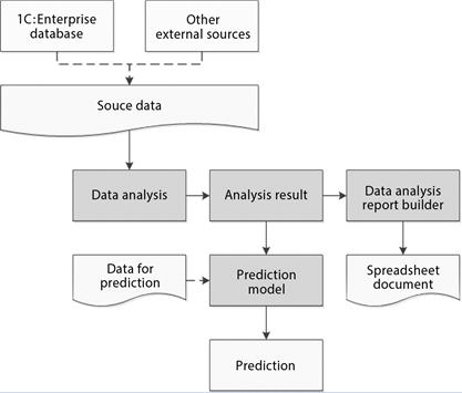
Fig. 454. Data analysis feature items interaction layout
The feature allows you to work both with data retrieved from the infobase and with data obtained from another source and previously loaded to a value table or a spreadsheet document.
By applying one of analysis types to the source data, it is possible to retrieve the result of analysis. The result of the analysis is a data behavior model. It can be displayed in the final document or saved for future use.
A further use of the analysis result is that a forecast model can be created based on it, which allows predicting the behavior of new data in accordance with the existing model.
For example, it is possible to analyze which products are bought together (in one invoice) and to save the forecast model created based on this analysis in the database. In the future, when creating a new invoice, the previously saved forecast model can be retrieved from the infobase, input new data contained in this invoice, and retrieve a forecast as the output i.e. the list of goods that the next customer will also buy (with a certain probability), if offered.
14.2.1. Main objects of the feature
Schematically, the relationship of data analysis and the main objects of the forecasting feature
can be shown as follows:
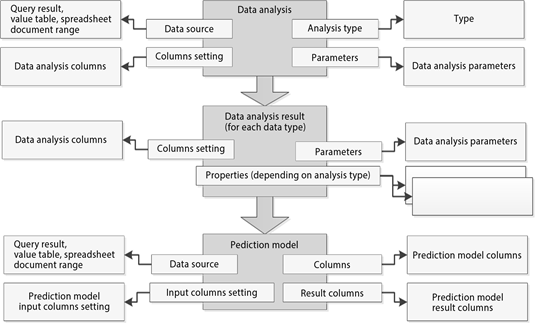
Fig. 455. Relationship of the main objects
Data analysis is an object that directly performs the data analysis. The data source, parameters, and source data are set for it. The result of this object operation is the data analysis result, where there is own object for using with the analysis result for each type of analysis:
-
DataAnalysisSummaryStatisticsResult
-
DataAnalysisAssociationRulesResult
-
DataAnalysisSequentialPatternsResult
-
DataAnalysisDecisionTreeResult
-
DataAnalysisClusterizationResult
Data analysis column settings are a collection of input data analysis columns. The type of data contained, role of the column, additional settings, depending on the type of analysis are specified for each column.
Data analysis parameters are a set of parameters for the data analysis being performed. The parameters depend on the analysis type. For example, for cluster analysis, the number of clusters into which the source objects are to be divided, the type of distance dimension between objects, etc. is specified.
Data source is source data for analysis. The data source can be the result of the query, cell area of the spreadsheet document, value table.
Data analysis result is a specific object containing information about the analysis result. Each type of analysis has its own result. For example, Decision tree analysis type will result in DataAnalysisDecisionTreeResult type object. In the future, the result can be output to a spreadsheet document using the data analysis report builder, can be output using programmatic access to its contents, and can be used to create a forecast model. Any data analysis result can be saved for later use.
Forecast model is a specific object that allows you to perform a forecast based on the input data (selection for the forecast, selection column and result settings, analysis result). The type of forecast model depends on the type of data analysis result. For example, a model created for Search for associations will be of the PredictionModelAssociationRules type. Such model can generate predictions of the following types: since this buyer has bought a given set of products, then with a certain probability they will buy another set of products. The input of the forecast model is the forecast data source. The result is a value table containing forecast values.
Input columns settings are a set of specific objects showing the matching between forecast model columns and forecast selection columns. For example, the Product forecast model column can correspond to the Products selection column.
Result columns settings allow you to control which columns will be placed in the resulting forecast model table. For example, to search for associations, it is possible to output the products that the client will most likely buy and the likelihood of such a purchase to the result.
Result columns are a value table consisting of columns specified in the settings of the resulting columns and containing the forecast data. The specific content is determined by the type of analysis.
14.2.2. Data analysis types
The data analysis and forecasting feature implements several types of data analysis:
-
General statistics
-
Search for associations
-
Search for sequences
-
Cluster analysis
-
Decision tree
14.2.2.1. General statistics
The General statistics analysis type is a feature for collecting general information about the data in the received data source. This type of analysis is intended for preliminary research of the analyzed information.
The analysis shows several characteristics of discrete and continuous fields. When a report is output to a spreadsheet document, pie charts are filled in to display the contents of the fields.
14.2.2.2. Search for associations
This type of analysis searches for groups of objects or characteristic values that are encountered together, and also searches for association rules. The search for associations can be used, for example, to determine the often-purchased products or services.
This analysis type can be used with hierarchical data, which allows, for example, finding rules not only for specific products but also for their groups. An important feature of this type of analysis is the capability to operate both with an object data source, where each column contains a certain characteristic of the object, and with an event source, where the characteristics of the object are located in one column.
14.2.2.3. Search for sequences
The Search for sequences analysis type allows you to identify the sequential chains of events in the data source. For example, these may be a chain of products or services that customers often buy consistently.
This type of analysis allows you to search by hierarchy, which makes it possible to track not only the sequence of specific events but also the sequence of parent groups.
14.2.2.4. Cluster analysis
Cluster analysis allows you to divide the source set of objects under study into groups of objects so that each object is more similar to objects from its group than to objects from other groups. Further analysis of the resulting groups, called clusters, makes it possible to determine what characterizes this or that group, to decide on the methods of operating the objects of different groups. For example, using cluster analysis, it is possible to divide customers with whom the company works into groups in order to apply different strategies when working with them.
Using the parameters of cluster analysis, the user can configure the algorithm that will be used for splitting, and also can dynamically change the composition of the characteristics considered in the analysis, adjust the weights for them.
A clusterization result can be displayed as a dendrogram, which is a specific type of chart designed for graphical display of cluster analysis results.
14.2.2.5. Decision tree
The Decision tree analysis type allows you to build a hierarchical structure of classifying rules displayed as a tree.
To build a decision tree, it is necessary to select a target attribute, which will be used to build a classifier, and a several input attributes that will be used to create rules. The target attribute may contain, for example, information about whether the client has moved to another service provider, whether the transaction was successful, whether the works have been performed efficiently, and so on. Input attributes, for example, may be the age of the employee, their work experience, the financial condition of the client, number of employees in the company, and so on.
The result of the analysis is presented in the form of a tree, each node of which contains some condition. To decide which class a certain object must belong to, go through the chain from the root to the leaf of the tree while answering questions in the nodes and passing to child nodes in case of an affirmative answer or to an adjacent node in case of a negative answer.
A set of analysis parameters allows you to adjust the accuracy of the resulting tree.
14.2.3. Forecast models
Forecast models generated by the feature are specific objects that are created based on the result of data analysis and allow you to automatically perform the forecast for new data in the future.
For example, the forecast model of the search for associations, built during the analysis of customer purchases, can be used when working with a purchasing customer in order to offer them the products that they will buy with a certain degree of probability together with the products they have chosen.
14.3. "General statistics" analysis type
You can use the General statistics analysis type for preliminary data analysis (before performing another type of analysis), and so on.
The source of the data to be analyzed can be the result of a query, a value table, or a cell area in a spreadsheet document.
The data in the source (in terms of the analysis conducted) can be continuous or discrete. The continuous ones include such types as Number, Date. The remaining types are discrete.
Obtaining different information is provided for columns of different types.
Discrete data:
-
Number of values. The number of values encountered in the data source column (NULL is not considered a value).
-
Number of unique values (excluding duplicate values).
-
Mode. The value that is most often found in the data source. If there are several values in the data that are encountered with the same frequency, the first found value is taken as the mode.
-
Frequency. The number of value occurrences in the data selection.
-
Relative frequency. It is defined as a ratio of the value occurrence number to the total number of values.
-
Cumulative frequency. It is calculated as the sum of the value frequency and the sum of the previous value frequencies in the data selection.
-
Cumulative relative frequency. It is calculated as the sum of the cumulative value frequency and the sum of the relative frequencies of the previous values.
Continuous data:
-
Number of values
-
Minimum value
-
Maximum value
-
Average value
-
Range. The difference between maximum and minimum values
-
Standard deviation
-
Median. A value lying in the middle of the selection
It should be noted that if several fields of different types are analyzed simultaneously, their analysis is carried out independently of each other (mutual correlation is excluded).
Consider these characteristics in an example.
The data selection (source of analysis) has the following items:
| Products | Count |
|---|---|
| Folding Kitchen Table | 1 |
| Round Stool | 2 |
| Coziness Sofa | 1 |
| Jeans Sofa | 1 |
| Jeans Armchair | 2 |
| Kitchen Table 0.9x1.7 | 1 |
| Comfort Sofa | 1 |
| Kitchen Table 0.9x1.7 | 1 |
| Summer Chair | 4 |
| Coziness Sofa | 1 |
| Folding Kitchen Table | 1 |
| Square Stool | 3 |
| Coziness Armchair | 2 |
| Coziness Armchair | 2 |
| Wardrobe Closet | 1 |
| Folding Kitchen Table | 1 |
| Square Stool | 2 |
| Dining Table | 1 |
| Summer Chair | 2 |
| Round Stool | 2 |
As a result of the data analysis, the following characteristics will be calculated for the Count field (Continuous analysis data type):
| Characteristic | Value |
|---|---|
| Total values | 20 |
| Min | 1 |
| Max | 4 |
| Avg | 1.6 |
| Range | 3 |
| Standard deviation | 0.8208 |
| Median | 1 |
The following characteristics will be obtained for the Products field:
| Characteristic | Value |
|---|---|
| Number of values | 20 |
| Number of unique values | 12 |
| Mode | Folding Kitchen Table |
The frequency table for the product values will be as follows:
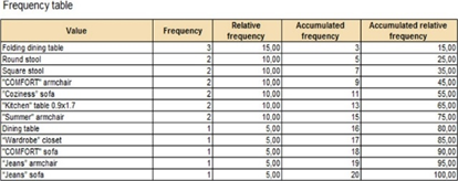
Fig. 456. Frequency table
Relative frequency in the form of a chart is shown below:
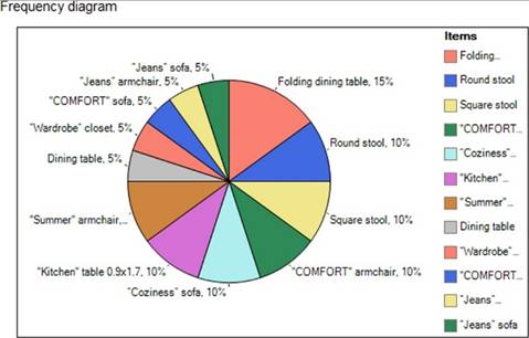
Fig. 457. Frequency chart
To perform this analysis, a code fragment similar to the one below can be used:
&AtClient
Procedure GeneralStatistics(Command)
Result = AnalysisGeneralStatistics();
EndProcedure
&AtServerNoContext
Function AnalysisGeneralStatistics()
Analysis = New DataAnalysis;
Analysis.AnalysisType = Type("DataAnalysisSummaryStatistics");
Query = New Query;
Query.Text = "
|SELECT
|Sales.Products, |Sales.Count
|FROM
|AccumulationRegister.Sales
AS Sales";
Analysis.DataSource = Query.Execute();
AnalysisResult = Analysis.Execute();
Builder = New DataAnalysisReportBuilder();
Builder.Template = Undefined;
Builder.AnalysisType = Type("DataAnalysisSummaryStatistics");
Spreadsheet = New SpreadsheetDocument;
Builder.Output(AnalysisResult, Spreadsheet);
Return Spreadsheet;
EndFunctionThe data analysis operations are performed in the server non-context function, which returns a spreadsheet document with the analysis results to the client. First, the DataAnalysis object is created. After this, the type of analysis performed is selected.
Further, the query is determined by the text. The query result is set as the analysis data source. The analysis itself is performed while executing the Execute() method of the DataAnalysis object.
The analysis itself has no tools of visualizing the result of the analysis obtained. For this purpose, the DataAnalysisReportBuilder object is used. When creating this object, the type of analysis performed is specified again. Then, the result of the analysis received is passed as the first parameter of the Output() method, and the second parameter is the previously created SpreadsheetDocument object.
At the end of the algorithm, the spreadsheet document with the result of the analysis is returned to the client to the Result processing attribute of SpreadsheetDocument type.
As a result, data similar to above will be retrieved.
14.4. "Search for associations" analysis type
As mentioned above, this type of analysis searches for frequently encountered combinations of objects or characteristic values. Using it, it is possible to identify groups of simultaneously purchased products, identify the most attractive sources of information (in the process of "optimizing" their costs), etc.
Schematically, the Search for associations analysis process can be represented as follows:
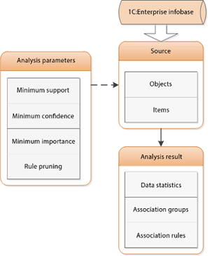
Fig. 458. "Search for associations" analysis layout
The data source can be the result of a query, a value table, or a cell area of a spreadsheet document. In terms of this analysis type, the source columns can be divided into the following:
-
NotUsed. It is ignored by analysis.
-
Object. Data from this column is used as analysis objects (or events). Based on the value of this column, the values of the other column (Item) belong to the same associated group.
-
Item. Data from this column is used to obtain stable groups of values, to build associative rules.
In addition to setting the types of columns, the following analysis parameters affect the result of the analysis:
-
MinSupport. Determines the minimum percentage of cases where a combination of items must occur. Groups whose value is less than the specified value are not included in the analysis result.
-
MinConfidence. Shows the minimum percentage of cases when the rule is observed.
-
MinImportance. Groups whose value is less than the specified value are not included in the analysis result.
-
PruneRulesType. One of the AssociationRulesPruneType system enumeration options:
-
Redundant. Cut off redundant rules.
-
Covered. Cut off rules covered by other rules.
-
As a result of the analysis, the following is retrieved:
-
Data information: number of objects, number of items, average number of items in the object, number of found groups, number of found association rules.
-
Found item groups. Specifies group content, number of cases, percentage of cases where this group occurs.
-
Found association rules. Specifies initial items, consequent (composition of items), percentage of cases, confidence, and importance of the rule.
Consider the features of this type of analysis on the following data selection (we will try to determine the composition of simultaneously purchased products):
| Recorder | Products |
|---|---|
| Invoice No. 000000001 | Folding Kitchen Table |
| Round Stool | |
| Invoice No. 000000002 | Coziness Sofa |
| Invoice No. 000000003 | Jeans Sofa |
| Jeans Armchair | |
| Invoice No. 000000005 | Kitchen Table 0.9x1.7 |
| Comfort Sofa | |
| Invoice No. 000000004 | Kitchen Table 0.9x1.7 |
| Summer Chair | |
| Coziness Sofa | |
| Invoice No. 000000006 | Folding Kitchen Table |
| Square Stool | |
| Invoice No. 000000007 | Coziness Armchair |
| Invoice No. 000000008 | Coziness Armchair |
| Invoice No. 000000009 | Wardrobe Closet |
| Invoice No. 000000010 | Folding Kitchen Table |
| Square Stool | |
| Dining Table | |
| Invoice No. 000000011 | Summer Chair |
| Round Stool |
The value of the recorder (products specified in one document is considered purchased at the same time) will be assumed as sign by which the data are attributed to one group. That is, Recorder will be analysis object and Products will be its item.
The following code fragment will be used for the analysis:
&AtClient
Procedure SearchForAssociations(Command)
Result = AnalysisSearchForAssociations();
EndProcedure
&AtServerNoContext
Function AnalysisSearchForAssociations()
Analysis = New DataAnalysis;
Analysis.AnalysisType = Type("DataAnalysisAssociationRules");
Query = New Query;
Query.Text = "
|SELECT
|Sales.Recorder, |Sales.Products
|FROM
|AccumulationRegister.Sales
AS Sales";
Analysis.DataSource = Query.Execute();
// The string is given as an
example. // This is the default
column type value. Analysis.ColumnsSetting.Products.ColumnType
= DataAnalysisColumnTypeAssociationRules.Item;
// The string is given as an
example. // This is the default prune
type value. Analysis.Parameters.PruneRulesType.Value
= AssociationRulesPruneType.Redundant;
AnalysisResult = Analysis.Execute();
Builder = New DataAnalysisReportBuilder();
Builder.Template = Undefined;
Builder.AnalysisType = Type("DataAnalysisAssociationRules");
Spreadsheet = New SpreadsheetDocument;
Builder.Output(AnalysisResult, Spreadsheet);
Return Spreadsheet;
EndFunctionThe result of the analysis will be as follows:
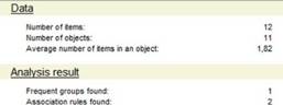
Fig. 459. "Search for associations" analysis result
The selection uses data from eleven documents (the reference is contained in the Recorder field), number of different items is twelve:
| Products |
|---|
| Folding Kitchen Table |
| Round Stool |
| Coziness Sofa |
| Jeans Sofa |
| Jeans Armchair |
| Kitchen Table 0.9x1.7 |
| Comfort Sofa |
| Summer Chair |
| Square Stool |
| Coziness Armchair |
| Wardrobe Closet |
| Dining Table |
The following product group is found:
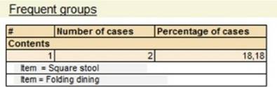
Fig. 460. Found product group
The whole group is found in the document only in two cases out of eleven (this is shown in the Number of cases and Percentage of cases columns).
The following association rules were retrieved:

Fig. 461. Association rules
Let us analyze the second of them. In two cases out of eleven in the document, the Rectangular stool item was encountered along with the Kitchen folding table item. Based on this, the percentage of cases was calculated: (2 / 11 * 100 = 18.18 %).
Confidence was calculated as follows: both product items were purchased in two cases, the Folding kitchen table product item was found in purchases 3 times. Based on this, the confidence is: 2 / 3 * 100 = 66.67 %.
Importance is defined as the ratio of the rule confidence to the percentage of finding a Rectangular stool in the purchased products. This item is found in two of the eleven documents (18.18%). Importance equals: 66.67 % / 18.18 % = 3.67.
14.4.1. Rule prune types
Let us take a look at an important parameter of this analysis type, which is PruneRulesType. Possible prune values are contained in the system enumeration AssociationRulesPruneType. They contain:
-
Covered
-
Redundant
Before proceeding to consider the features of the prune options, consider a few general points applicable to the association rules.
Any rule consists of an antecedent and a consequent. Example:
-
Antecedent: If Product 1 is bought.
-
Consequent: Then Product 2 will be bought.
At the same time, it is necessary to remember that the consequent occurs with a certain confidence. When pruning rules, probabilistic characteristics can be considered, or they can be ignored (only the content of the rule is important).
14.4.1.1. Pruning covered rules
Consider the Covered pruning option.
The rule can be covered both by antecedent and by consequent. Example:
-
Rule 1: If products 1 and 3 have been bought, Then product 2 will be bought.
-
Rule 2: If product 1 has been bought, Then product 2 will be bought.
In this case, rule 1 will be considered covered as the antecedent of the first rule is "redundant" in relation to the antecedent of the second rule.
Example of coverage by consequent:
-
Rule 1: If product 1 has been bought, Then products 2 and 3 will be bought.
-
Rule 2: If product 1 has been bought, Then product 3 will be bought.
Rule 2 will be covered by consequent as the consequent of rule 1 is more complete.
14.4.1.2. Pruning redundant rules
Coverage does consider the probabilistic characteristics of the rules. They are considered if the Redundant pruning option is used.
A rule will be considered redundant by antecedent if it is covered by the antecedent and its confidence is equal to the confidence of the covering rule. Example:
-
Rule 1: If products 1 and 3 have been bought, Then product 2 will be bought with 75% confidence.
-
Rule 2: If product 1 has been bought, Then product 2 will be bought with 75% confidence.
Rule 1 is redundant in relation to rule 2. It contains an additional condition that does not introduce a "disturbance" to the probabilistic characteristics of the rule.
Rule 1 will be considered excessive by consequence if the number of cases of this rule is equal to the number of cases of the covering rule.
-
Rule 1: If product 1 has been bought, Then products 2 and 3 will be bought in three cases.
-
Rule 2: If product 1 has been bought, Then product 3 will be bought in three cases.
Rule 2 will be considered redundant in relation to rule 1 as it contains a simpler consequent with the same probabilistic characteristics.
14.5. "Search for sequences" analysis type
This type of analysis allows you to identify chains of occurring events (sequence templates). It can be used when one of the important analyzed indicators is the sequence of events occurrence in time. For example, you can identify the sequence of products that are purchased one after another for a certain period of time, and so on.
Schematically, the Search for sequences analysis process can be represented as follows:
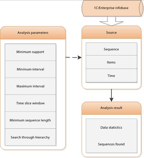
Fig. 462. "Search for sequences" analysis layout
The data source can be the result of a query, a value table, a cell area of a spreadsheet document. In terms of this analysis type, the source columns can be divided into the following:
-
NotUsed. It is ignored by analysis.
-
Sequence. Data from this column is used for analysis as a sequence event object. Based on the value of this column, analysis associates the data with a single chain of events;
-
Item. Data from this column is used as sequence items.
-
Time. This column determines the time of the event. Presence of this column is mandatory when conducting this type of analysis.
In addition to setting the types of columns, the following analysis parameters affect the result of the analysis:
-
MinSupport. The minimum percentage of sequences where the found sequence template occurs.
-
MinInterval. Indicates that the minimum sequence interval is set (an interval measurement unit and a unit conversion factor must be set).
-
MaxInterval. Indicates that the maximum sequence interval is set (an interval measurement unit and a unit conversion factor must be set).
-
TimeSliceWindow. Indicates that the time slice window is set (a unit of time slice window and a unit conversion factor must be set).
-
MinLength. The minimum length of the desired sequences.
-
FindInHierarchy. Indicates that search by hierarchy is performed (applies to the Item type columns).
Several properties use DataAnalysisTimeIntervalUnitType. This system enumeration contains the following values:
| Second | |
| Minute | CurrentMinute |
| Hour | CurrentHour |
| Day | CurrentDay |
| Week | CurrentWeek |
| Ten-day period | CurrentTenDays |
| Month | CurrentMonth |
| Quarter | CurrentQuarter |
| HalfYear | CurrentHalfYear |
| Year | CurrentYear |
The main result of the analysis is the sequence templates found. These templates contain the following information:
-
Sequence template content.
-
Number of cases where this sequence occurred.
-
Maximum intervals between events (if there are two events, there is one interval).
-
Minimum intervals between events (if there are two events, there is one interval).
-
Percentage of cases when this sequence was executed.
-
Average intervals between events (if there are two events, there is one interval).
We will consider the specifics of performing this type of analysis on the example of the following data selection:
| Counterparty | First purchase | Second purchase | Third purchase | Interval |
|---|---|---|---|---|
| Edward Brown | Folding Kitchen Table | Coziness Sofa | Coziness Armchair | 25 days, 31 days |
| Round Stool | ||||
| John Smith | Jeans Sofa | |||
| Jeans Armchair | ||||
| Kevin Williams | Kitchen Table 0.9x1.7 | Coziness Armchair | 43 days | |
| Summer Chair | ||||
| Coziness Sofa | ||||
| David Jones | Folding Kitchen Table | |||
| Square Stool | ||||
| Robert Johnson | Folding Kitchen Table | |||
| Square Stool | ||||
| Dining Table | ||||
| Mark Wilson | Kitchen Table 0.9x1.7 | Wardrobe Closet | Summer Chair | 58 days, 29 days |
| Comfort Sofa | Round Stool |
Data from the Counterparty column will determine whether an item belongs to a certain chain of events. It means that this data determines the analysis sequence. Products will be the retrieved sequence item.
For analysis, a code fragment similar to the one below can be used:
&AtClient
Procedure SearchForSequences(Command)
Result = AnalysisSearchForSequences();
EndProcedure
&AtServerNoContext
Function AnalysisSearchForSequences()
Analysis = New DataAnalysis;
Analysis.AnalysisType = Type("DataAnalysisSequentialPatterns");
Query = New Query;
Query.Text = "
|SELECT
|Sales.Counterparty, |Sales.Products, |Sales.Period
|FROM
|AccumulationRegister.Sales
AS Sales";
Analysis.DataSource = Query.Execute();
Analysis.ColumnsSetting.Period.ColumnType
= DataAnalysisColumnTypeSequentialPatterns.Time;
AnalysisResult = Analysis.Execute();
Builder = New DataAnalysisReportBuilder();
Builder.Template = Undefined;
Builder.AnalysisType = Type("DataAnalysisSequentialPatterns");
Spreadsheet = New SpreadsheetDocument;
Builder.Output(AnalysisResult, Spreadsheet);
Return Spreadsheet;
EndFunctionThe Period field is determined as Time directly from the code (not determined by the analysis independently).
The default analysis parameters are:
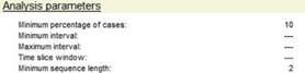
Fig. 463. Analysis parameters
After analysis, the following general data was retrieved:
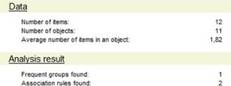
Fig. 464. General analysis data
The number of items is twelve. Exactly that many product items are found in the above data selection.
Two sequences have been found:

Fig. 465. Found sequences
The first sequence occurs in two cases out of five. Proceeding from this, the percentage of cases is 40%. Since the depth of a sequence is 2, there is one value for each of the reducible intervals.
14.6. "Decision tree" analysis type
Using this type of analysis, a causal hierarchy of conditions can be obtained, leading to a specific solution. For example, to obtain a condition tree under which (with a certain probability) it is possible to understand the reason for termination of contracts with the customers of the company, determining the conditions affecting the option of the contract being signed. It is possible to carry out "profiling" of company managers for various types of its clients, and so on.
Schematically, the Decision tree analysis process can be represented as follows:
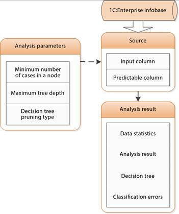
Fig. 466. "Decision tree" analysis layout
In terms of this analysis type, the source columns can be divided into the following:
-
NotUsed
-
Input
-
Predictable
Applied analysis parameters:
-
MinCaseCount. Minimum number of items in the node.
-
MaxDepth. Maximum tree depth.
-
SimplificationType. Decision tree simplification type.
As a result of the analysis, the following can be retrieved:
-
Decision tree
-
Classification errors
Let us deal with the features of this type of analysis on the example of the following data selection:
| Counterparty | Number of retail shops | Number of vehicles | Company operation time | Contract signing time | Contract type | Relations condition |
|---|---|---|---|---|---|---|
| Smith CJSC | 1 | 0 | Less than a year | Less than a year | Dealer | Contract violation |
| Furniture CJSC | 15 | 4 | From three to ten years | Less than a year | Distributor | Terminated by counterparty |
| Furniture CJSC | 1 | 10 | From three to ten years | From one to three years | Distributor | Terminated by counterparty |
| Forest LLC | 1 | 1 | From one to three years | Less than a year | Dealer | Terminated by counterparty |
| Shop No. 15 | 1 | 1 | Over ten years | From three to ten years | Permanent partner | Not terminated |
| Gross LLC | 3 | 2 | Less than a year | Less than a year | Permanent partner | Not terminated |
| Consultant LLC | 7 | 3 | From three to ten years | From one to three years | Permanent partner | Terminated by counterparty |
| Trust LLC | 2 | 2 | Over ten years | From three to ten years | Permanent partner | Not terminated |
| Individual Entrepreneur Taylor | 0 | 1 | Less than a year | Less than a year | Dealer | Not terminated |
For analysis, a code fragment similar to the one below can be used:
&AtClient
Procedure DecisionTree(Command)
Result = AnalysisDecisionTree();
EndProcedure
&AtServerNoContext
Function AnalysisDecisionTree()
Analysis = New DataAnalysis;
Analysis.AnalysisType = Type("DataAnalysisDecisionTree");
Group = Catalogs.Counterparties.FindByDescription("Legal entities");
Query = New Query;
Query.Text = "
|SELECT
|Counterparties.Ref, |Counterparties.RetailShopsCount, |Counterparties.VehiclesCount, |Counterparties.CompanyOperationTime, |Counterparties.ContractSigningTime, |Counterparties.ContractType, |Counterparties.RelationsTermination
|FROM
|Catalog.Counterparties AS
Counterparties
|WHERE
|(Not
Counterparties.IsFolder AND Counterparties.Parent = &Parent)";
Query.SetParameter("Parent", Group);
Analysis.DataSource = Query.Execute();
Analysis.Parameters.SimplificationType.Value
= DecisionTreeSimplificationType.DontSimplify;
AnalysisResult = Analysis.Execute();
Builder = New DataAnalysisReportBuilder();
Builder.Template = Undefined;
Builder.AnalysisType = Type("DataAnalysisDecisionTree");
Spreadsheet = New SpreadsheetDocument;
Builder.Output(AnalysisResult, Spreadsheet);
Return Spreadsheet;
EndFunctionThe analysis resulted in the following decision tree:
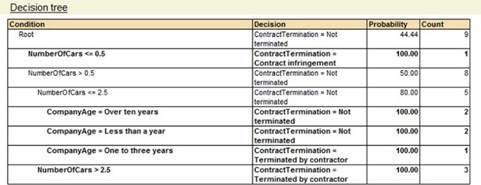
Fig. 467. Decision tree
This tree can be displayed as follows:
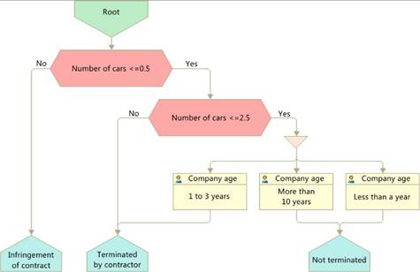
Fig. 468. Decision tree presentation as a scheme
Classification errors show in which cases the obtained rules diverge from the reality (initial data selection):
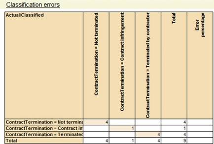
Fig. 469. Classification errors
Based on the above data, it is clear that there are no errors in the resulting classification, that is, the data in the actual selection match the classification data.
The example above has been obtained based on the DontSimplify value of SimplificationType analysis parameter. This parameter value is set programmatically in the example above. If the value of the Simplify parameter is set, the decision tree will look as follows:
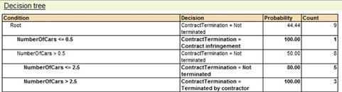
Fig. 470. Decision tree
Simplification of the tree is that according to certain rules (formulas, which will be discussed below) tree nodes are turned into leaves (unnecessary branching is cut off).
When deciding whether a node is to be converted to a leaf, the following indicators are considered:
-
Errors. Number of errors in a node.
-
ChildErrors. Number of errors in child nodes.
-
Leaves. Number of leaves in a node.
-
Cases. Number of cases.

The decision to convert a node to a leaf is made if the following condition is met:

In our example, for the Company operation time nodes, the condition is met (0.5 <1).
Due to the use of simplifications, classification errors also appeared, which is shown in the analysis result:
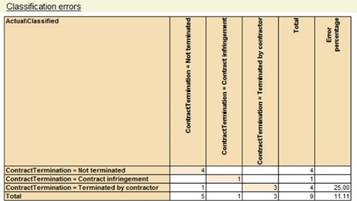
Fig. 471. Classification errors
For example, there is a case when the real data selection contains the Terminated by counterparty value. However, according to the retrieved classification, it must contain the Not terminated value and so on.
14.7. "Clusterization" analysis type
Cluster analysis is a mathematical procedure for multidimensional analysis, which allows you to group objects into clusters based on a set of indicators characterizing the objects. Objects must be grouped so that objects in one cluster are more homogeneous and similar compared to objects in other clusters.
The basis of this analysis is the calculation of distance between objects. Based on the distances between the objects these are grouped into clusters. The distance can be determined in different ways (according to different metrics). The following metrics are available:
-
Euclidean metric
-
Squared Euclidean metric
-
City block metric
-
Maximum metric.
After determining the distances between objects, one of several algorithms for distributing objects among clusters can be used. The following clustering methods are available:
-
Nearest neighbor
-
Furthest neighbor
-
K-means
-
Centroid
Schematically, the functionality of cluster analysis can be presented as follows:
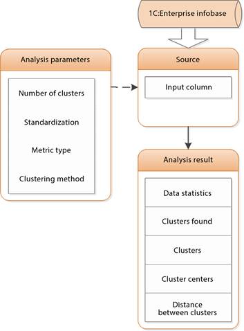
Fig. 472. Cluster analysis layout
The data source is passed to the DataAnalysis object. The data source can be the result of a query, a value table, a cell area of a spreadsheet document. Source columns are defined as input or unused. It should be noted that all the column values are contained in the DataAnalysisColumnTypeClusterization system enumeration. This enumeration contains more values (not only unused and input ones), but the other values are used when building forecasts.
The analysis is performed in accordance with the set analysis parameters.
We will use the following code fragment as an example illustrating the capability of cluster analysis:
&AtClient
Procedure ClusterAnalysis(Command)
Result = AnalysisClusterization();
EndProcedure
&AtServerNoContext
Function AnalysisClusterization()
Analysis = New DataAnalysis;
Analysis.AnalysisType = Type("DataAnalysisClusterization");
Group = Catalogs.Counterparties.FindByDescription("Legal entities");
Query = New Query;
Query.Text = "
|SELECT
|Counterparties.Ref, |Counterparties.RetailShopsCount, |Counterparties.VehiclesCount, |Counterparties.CompanyOperationTime, |Counterparties.ContractSigningTime, |Counterparties.ContractType, |Counterparties.RelationsTermination
|FROM
|Catalog.Counterparties AS
Counterparties
|WHERE
|(Not
Counterparties.IsFolder AND Counterparties.Parent = &Parent)";
Query.SetParameter("Parent", Group);
Analysis.DataSource = Query.Execute();
// Selecting metric.
Analysis.Parameters.DistanceMetric.Value
= DataAnalysisDistanceMetricType.SquaredEuclidean;
// Selecting clusterization
method. Analysis.Parameters.ClusterizationMethod.Value
= ClusterizationMethod.KMeans;
AnalysisResult = Analysis.Execute();
Builder = New DataAnalysisReportBuilder();
Builder.Template = Undefined;
Builder.AnalysisType = Type("DataAnalysisClusterization");
Spreadsheet = New SpreadsheetDocument;
Builder.Output(AnalysisResult, Spreadsheet);
Return Spreadsheet;
EndFunctionQuery is performed by the Counterparties catalog. According to the query condition, only detailed catalog entries from the Legal entities group are selected.
Execution of the above code will result in the following values being defined as the initial data analysis settings. Some of them are set explicitly, some of them are set by default:
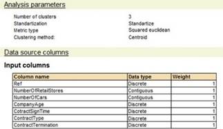
Fig. 473. Analysis parameters
The composition of the columns was determined based on the composition of the query selection fields. By default, they are defined with equal weight. For the Number and Date types, the Contiguous data type is defined. For other types, the Discrete type is defined. If it is necessary to change the parameters of the columns, this can be done by analogy with the fragment below:
Analysis.ColumnsSetting.VehiclesCount.AdditionalParameters.Weight = 2;In this line, the weight is increased for the VehiclesCount column.
The selection of data for which the analysis will be performed has the following content:
| Counterparty | Number of retail shops | Number of vehicles | Company operation time | Contract signing time | Contract type | Relations condition |
|---|---|---|---|---|---|---|
| Smith CJSC | 1 | 0 | Less than a year | Less than a year | Dealer | Contract violation |
| Furniture CJSC | 15 | 4 | From three to ten years | Less than a year | Distributor | Terminated by counterparty |
| Furniture CJSC | 1 | 10 | From three to ten years | From one to three years | Distributor | Terminated by counterparty |
| Forest LLC | 1 | 1 | From one to three years | Less than a year | Dealer | Terminated by counterparty |
| Shop No. 15 | 1 | 1 | Over ten years | From three to ten years | Permanent partner | Not terminated |
| Gross LLC | 3 | 2 | Less than a year | Less than a year | Permanent partner | Not terminated |
| Consultant LLC | 7 | 3 | From three to ten years | From one to three years | Permanent partner | Terminated by counterparty |
| Trust LLC | 2 | 2 | Over ten years | From three to ten years | Permanent partner | Not terminated |
| Individual Entrepreneur Taylor | 0 | 1 | Less than a year | Less than a year | Dealer | Not terminated |
The result of the analysis will be obtained in the following form:
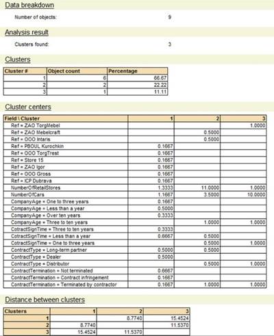
Fig. 474. Cluster analysis result
Note that data is retrieved on the clusters found (their number, centers, distances between them) as a result of the analysis. The analysis does not result in obtaining the data on which objects (in our case, counterparties) are included in which clusters. This behavior is observed if the parameters of the analysis performed are not explicitly set (namely, the TableFillType parameter).
In order to see the distribution of objects in clusters as a result of the analysis, it is necessary to define the following line of code before performing the analysis (but after determining its type):
Analysis.Parameters.TableFillType.Value
= DataAnalysisResultTableFillType.UsedFields;14.7.1. Used metrics
Consider that despite the fact that in the previous example the input columns were of continuous type (for this type, the concept of "distance" is obvious), columns of discrete types (references to catalogs, enumeration values, and so on) can also be used in analysis.
Let us consider the metrics that can be used when conducting cluster analysis.
14.7.1.1. Euclidean metric
In this metric, the distance between two objects is calculated by the formula:

Where:
-
Xi, Yi are attribute values of two objects. The distance is determined between these values.
-
Wi is a weighting factor of an attribute. It is set in the analysis column.
-
i is an attribute number, from 1 to n.
-
n is the number of attributes.
Suppose that objects are characterized by one property, which is 9 for one object and 5 for another object. The weighting factor of this attribute is one. The distance between the objects will be:

14.7.1.2. Squared Euclidean metric
In this metric, the distance between two objects is calculated by the formula:

Where:
-
Xi, Yi are attribute values of two objects. The distance is determined between these values.
-
Wi is a weighting factor of an attribute. It is set in the analysis column.
-
i is an attribute number, from 1 to n.
-
n is the number of attributes.
Suppose that objects are characterized by one property, which is 5 for one object and 3 for another object. The weighting factor of this attribute is two. The distance between the objects will be:
14.7.1.3. City block metric
In this metric, the distance between two objects is calculated by the formula:

Where:
-
Xi, Yi are attribute values of two objects. The distance is determined between these values.
-
Wi is a weighting factor of an attribute. It is set in the analysis column.
-
i is an attribute number, from 1 to n.
-
n is the number of attributes.
Suppose that objects are characterized by two attributes that have values 3 and 5, 7 and 3. The weight of the first one is 2, the weight of the second one is 1:
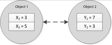
Fig. 475. Object characteristics

14.7.1.4. Maximum metric
In this metric, the distance between two objects is calculated by the formula:

Where:
-
Xi, Yi are attribute values of two objects. The distance is determined between these values.
-
Wi is a weighting factor of an attribute. It is set in the analysis column.
-
i is an attribute number, from 1 to n.
-
n is the number of attributes.
Suppose that objects are characterized by two attributes that have values 3 and 5, 7 and 3. The weight of the first one is 2, the weight of the second one is 1.
14.7.2. Clusterization methods
A clustering method option determines, based on what principles an object is attributed to one group or another, according to which algorithm generation of clusters is performed.
The goal of any clustering algorithm is to:
-
Minimize the variability within clusters
-
Maximize the variability between clusters
Differences between the methods will be considered on the objects presented in the figure (see fig. 476).
Assume that the objects form two groups. The first one consists of objects 1, 2 and 3. The second group consists of objects 4, 5 and 6.
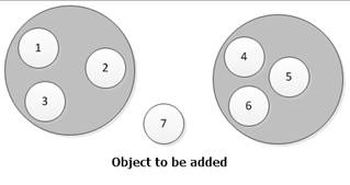
Fig. 476. Object groups
14.7.2.1. Nearest neighbor
The clustering method where the object joins the group for which the distance to the nearest object is minimal.
In this example, object 7 will be included in the group in which object 4 is located. The closest objects of the two groups are objects 4 and 3. The distance to object 4 is minimal.
14.7.2.2. Furthest neighbor
The clustering method where the object joins the group for which the distance to the furthest object is minimal.
In this example, object 7 will be included in the group in which object 5 is located. The closest objects of the two groups are objects 1 and 5. The distance to object 5 is less.
14.7.2.3. Centroid
The clustering method where the object joins the group for which the distance to the center of gravity is minimal:
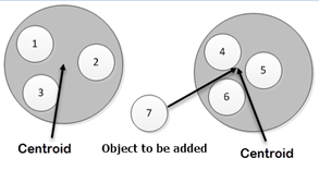
Fig. 477. Object groups
In the example in the figure, object 7 will be added to the group containing objects 4, 5 and 6. The distance to the center of gravity (of some mythical object with average values of attributes) is minimal.
14.7.2.4. K-means
In this method, the objects that are first in the selection are selected. They are considered cluster centers. Next, the next object is selected and, in accordance with the distance to the centers of the clusters, it is attributed to a particular cluster. The center of the cluster which the object was added to is recalculated.
The procedure is repeated until the exhaustive search of all the objects. Then a new selection of objects is made again (starting with the first one). The procedure is repeated as long as the centers of the clusters change:
Fig. 478. Objects location example
Suppose that objects 1 and 2 are arbitrarily chosen as centers of clusters. Object 3 is added to a cluster which center is object 1. The center of the first cluster is recalculated (it is located between object 1 and 3). Object 4 is added to the second cluster (its center is also recalculated).
After iterating through all the analyzed objects, objects 1 and 3 belong to the first cluster, and other objects belong to the second cluster (its center might be located in the center of a triangle of objects 4, 7, 6).
Then again, objects are selected and distributed among clusters (relatively constantly calculated cluster centers).
Somewhere on the third sample of objects, most likely, object 2, which was originally the center of the second cluster, will be attributed to the first cluster.
At the end of the algorithm, objects 1, 2, 3 will be assigned to the first cluster. Objects 4, 5, 6, 7 will be assigned to the second cluster.
14.7.2.5. Data output to a dendrogram
When outputting cluster analysis data, if an algorithm other than the k-means is used, the results of cluster analysis are output in the form of a dendrogram (the analysis algorithm must provide for outputting the distribution of the analyzed objects by clusters):
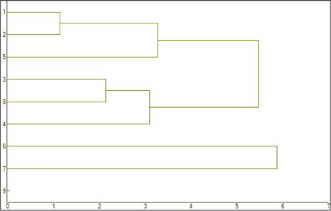
Fig. 479. Dendrogram
Chapter 15. Data exchange features
15.1. Tasks and goals
15.1.1. General information
Data exchange features are a set of 1C:Enterprise tools for arranging data exchange between various infobases, as well as between infobases and external software systems. Data exchange features can be divided into two levels:
-
Universal data exchange features
-
Distributed infobases
15.1.2. Universal data exchange features
Universal data exchange features can be used both together and separately, in various combinations, for arranging the data exchange from the 1C:Enterprise infobases with various software systems. Other 1C:Enterprise infobases can act as software systems which the exchange is arranged with. In this case, the infobases exchanging among themselves may in general have different configurations.
In addition, the universal data exchange features can be used to arrange exchange with software not based on 1C:Enterprise. The following factors contribute to this:
-
The data exchange format is based on the XML language, which is currently a generally accepted tool of presenting data.
-
Due to their modular arrangement and high flexibility, data exchange tools can be used to arrange various data exchange schemes.
-
Protocols provided by the data exchange features are simple and can be replicated in external software systems.
15.1.3. Distributed infobases
A distributed infobase is a hierarchical structure consisting of separate 1C:Enterprise infobases being nodes of the distributed infobase, between which data exchange is arranged to synchronize the configuration and data.
Distributed infobase management features are based on universal data exchange features, but contain some additional functions that are not available through universal features.
The main difference between distributed infobases and universal data exchange features is that universal data exchange features allow building fairly arbitrary data exchange schemes, while distributed infobases have a narrower specialization and also transfer configuration changes to subordinate nodes.
15.2. Universal data exchange features
15.2.1. General information
The universal data exchange features may include:
-
XML documents reading and writing tools
-
XML serialization
-
Exchange plans
15.2.2. XML documents reading and writing tools
The participants of the data exchange are supposed to exchange messages in XML format. Thus, the XML documents reading and writing tools are the basic level of data exchange.
XML documents reading and writing tools ensure that XML documents are handled in the most general way. This set of tools does not define the methods for presenting 1C:Enterprise data in XML format.
1C:Enterprise tools for reading and writing XML documents include: XMLReader, XMLWriter, and XSLTransform. The platform also supports handling XML data in the FastInfoset format, for which purpose the FastInfosetWriter and FastInfosetReader objects exist.
15.2.3. XML serialization
The main task of XML serialization is to support reading/writing 1C:Enterprise data objects to/from XML.
Basic tools for reading and writing XML documents do not provide a sufficient basis for solving this problem. They do not define the presentation of the 1C:Enterprise data in XML and do not provide tools for reading/writing data objects to/from XML in the accepted format as a whole.
15.2.3.1. Data presentation in XML serialization
Ultimately, each data object of 1C:Enterprise is represented as an XML element containing the value of the data object.
In terms of representation in XML, the value types are divided into simple and complex.
Simple data types include the types which values are represented by the XML serialization subsystem as XML elements with text content only.
Values of complex types are represented as XML elements containing nested elements.
An XML data type is assigned to each of 1C:Enterprise data types, the values of which can be represented in XML.
Each XML data type is characterized by the type name and the namespace which the type belongs to.
The XML data type can be as follows:
-
One of the types defined in the XML Schema Part 2 document: Datatypes of W3C consortium (namespace: http://www.w3.org/2001/XMLSchema).
-
Predefined 1C:Enterprise type (namespace: http://v8.1c.ru/data).
-
Type derived from 1C:Enterprise configuration metadata (does not belong to any namespace).
The XML data type can be specified explicitly in the representation of a data object in XML. To specify an XML data type, the XML element containing the value representation must contain a type attribute that belongs to the http://www.w3.org/2001/XMLSchema-instance namespace, which value contains the XML data type.
Another way to specify the XML data type is the name of the XML root element containing the value representation. The name of the root element representing the data object is not strictly specified and can be arbitrary. However, if the name of the root element is not specified when writing a value in XML, it will be set according to the type of the value being written. When reading data from XML, the value type, if it is not specified in the type attribute, can be set based on the root element name.
When considering examples of representing different values in XML and in further discussion, we will proceed from the assumption that the following namespace matches are defined:
xmlns:xsd="http://www.w3.org/2001/XMLSchema"
xmlns:xsi="http://www.w3.org/2001/XMLSchema
instance"
xmlns:v8="http://v8.1c.ru/data"15.2.3.1.1. Representation of simple type values in XML
The simple types it terms of representation in XML are the following 1C:Enterprise types:
-
Number
-
String
-
Date
-
Boolean
-
BinaryData
-
NULL
-
UUID
-
ValueStorage
-
All links to database objects
-
References to enumerations defined in metadata
Number
Description:
The Number type matches the decimal XML data type belonging to the http://www.w3.org/2001/XMLSchema namespace.The rules for representing values of this type are defined in the XML Schema Part 2 document: Datatypes.
Example:
<!-- Root element name is not explicitly specified -->
<decimal>45684.087</decimal>
<!-- XML root element name is explicitly specified -->
<Amount>523</Amount>
<!-- XML data type is explicitly specified -->
<Data
xsi:type="xsd:decimal">64793.01</Data>String
Description:
The String type corresponds to the string data type from the http://www.w3.org/2001/XMLSchema namespace. String is written in XML as is.Example:
<!-- Root element name is not explicitly specified -->
<string>This is string</string>
<!-- XML root element name is explicitly specified -->
<Name>Smith</Name>
<!-- XML data type is explicitly specified -->
<Data
xsi:type="xsd:string">This is string</Data>Date
Description:
The Date type values are represented as YYYY-MM-DDTHH:MM:SS, where:-
YYYY. Year in four digits.
-
MM. Month in two digits.
-
DD. Day of the month in two digits.
-
T. Latin letter T.
-
HH. Hour of the day.
-
MM. Minute.
-
SS. Second.
This date format is defined as valid in XML Schema Part 2 document: Datatypes.
Example:
<!-- Root element name is not explicitly specified -->
<dateTime>2008-11-21T12:00:00</dateTime>
<!-- XML root element name is explicitly specified -->
<Started>2001-10-30T19:00:00</Started>
<!-- XML data type is explicitly specified -->
<Data
xsi:type="xsd:dateTime">1980-08-25T10:00:00</Data>Boolean
Description:
The Boolean type corresponds to the boolean data type from the http://www.w3.org/2001/XMLSchema namespace.The False value is represented by the false string, and the True value is represented by the true string. This format is provided in XML Schema Part 2 document: Datatypes.
Example:
<!-- Root element name is not explicitly specified -->
<boolean>false</boolean>
<!-- XML root element name is explicitly specified -->
<Posted>true</Posted>
<!-- XML data type is explicitly specified -->
<Data
xsi:type="xsd:boolean">true</Data>BinaryData
Description:
The BinaryData type matches the base64Binary XML data type belonging to the http://www.w3.org/2001/XMLSchema namespace.Values of this type represent binary data encoded using the Base64 algorithm described in RFC 2045: https://datatracker.ietf.org/doc/html/rfc2045.html.
Example:
<!-- Root element name is not explicitly specified -->
<base64Binary>YWJjZGVm</base64Binary>
<!-- XML root element name is explicitly specified -->
<BinaryData>YWJjZGVm</BinaryData>
<!-- XML data type is explicitly specified -->
<Data
xsi:type="xsd:base64Binary">YWJjZGVm</Data>NULL
Description:
The NULL type matches the Null XML data type belonging to the http://v8.1c.ru/data namespace. This type has a single value that is manifested by an empty string.Example:
<!-- Root element name is not explicitly specified -->
<v8:Null/>
<!-- XML root element name is explicitly specified -->
<Selected/>
<!-- XML data type is explicitly specified -->
<Data
xsi:type="v8:Null"/>UUID
Description:
The UUID type matches the UUID XML data type belonging to the http://v8.1c.ru/data namespace.Values of this data type are presented in XML in compliance with common practice and standards (ISO-11578, DCE 1.1: Remote Procedure Call – Universal Unique Identifier).
Example:
<!-- Root element name is not explicitly specified -->
<v8:UUID>3294be0f-c039-41a9-bd65-596da0dcfe68</v8:UUID>
<!-- XML root element name is explicitly specified -->
<Id>da035e32-3f7a-4d87-41a9-accf7db8cb4b</Id>
<!-- XML data type is explicitly specified -->
<Data
xsi:type="v8:UUID">08839b0b-5ec3-4a53-a9f5-173312316919</Data>ValueStorage
Description:
The ValueStorage type matches the ValueStorage XML data type belonging to the http://v8.1c.ru/data namespace.Values of this type are represented in XML as ValueStorage data saved in a file, and then encoded using the Base64 algorithm.
Example:
<!-- Root element name is not explicitly specified -->
<v8:ValueStorage>AQEOAAAAAAAAAO+7v3siUyIsIjHQoSJ9</v8:ValueStorage>
<!-- XML root element name is explicitly specified -->
<Data>AQEOAAAAAAAAAO+7v3siUyIsIjHQoSJ9</Data>
<!-- XML data type is explicitly specified -->
<Data
xsi:type="v8:ValueStorage">AQEOAAAAAAAAAO+7v3siUyIsIjHQoSJ9</Data>Links to database objects
Description:
Each type of database object reference has its own XML data type. The XML data type name for references to database objects matches the English name of the 1C:Enterprise reference value type.So, for example, for the Currencies catalog, the English name of the reference type will be CatalogRef.Currencies. The corresponding XML data type will be spelled in the same fashion.
The XML data types for references to database objects do not belong to any namespace.
Reference values are represented in XML as values of the UUID type obtained from references.
Example:
<!-- Root element name is not explicitly specified -->
<CatalogRef.Banks>911b5b8b-11f5-4993-9673-2c9a7a8995d5</CatalogRef.Banks>
<!-- XML root element name is explicitly specified -->
<Ref>911b5b8b-11f5-4993-9673-2c9a7a8995d5</Ref>
<!-- XML data type is explicitly specified -->
<CatalogRef.Banks>911b5b8b-11f5-4993-9673-2c9a7a8995d5</CatalogRef.Banks>References to enumerations defined in metadata
Description:
Each type of enumeration value references defined in the configuration has its own XML data type. The XML data type name for references to enumeration values matches the English name of the 1C:Enterprise type.Thus, for example, for the AddressTypes enumeration, the English name of the value reference type will be EnumRef.AddressTypes. The corresponding XML data type will be spelled in the same fashion.
The XML data types for enumeration value references do not belong to any namespace. In XML, enumeration value references are represented as the name of the corresponding enumeration value.
Example:
<!-- Root element name is not explicitly specified -->
<EnumRef.AddressTypes>Registered</EnumRef.AddressTypes>
<!-- XML root element name is explicitly specified -->
<Ref>Registered</Ref>
<!-- XML data type is explicitly specified -->
<Data
xsi:type="EnumRef.AddressTypes">Business</Data>15.2.3.1.2. Representation of compound type values in XML
Compound types whose values can be represented in XML include the following 1C:Enterprise types:
-
Type
-
TypeDescription
-
ConstantValueManager.<Constant name>
-
All database objects
-
Register, sequence, and recalculation record sets
-
ObjectDeletion
Type
Description:
The Type type matches the XML Type data type belonging to the http://v8.1c.ru/data namespace. The XML element representing a value of this type contains a text with the name of the XML type that matches the 1C:Enterprise data type.At first glance, the Type type does not refer to compound data types but to simple ones, since the element representing the value of this type does not contain nested elements. However, it is not the case. Indeed, it does not contain nested elements. Yet, the text of the element containing the name of the XML data type contains a namespace prefix of the type that must be defined in an element or one of its parent elements, which makes the text of such element not quite self-contained. That is why the given type does not qualify as a simple one.
Example:
<!-- Root element name is not explicitly specified -->
<v8:Type>v8:ValueStorage</v8:Type>
<!-- XML root element name is explicitly specified -->
<Tp>xsd:string</Tp>
<!-- XML data type is explicitly specified -->
<Data
xsi:type="v8:Type">v8:ValueStorage<Data>TypeDescription
Description:
The TypeDescription type matches the TypeDescription XML data type belonging to the http://v8.1c.ru/data namespace. The root element that represents the value of the TypeDescription type includes a series of nested elements, each of them containing a certain part of the type description.The nested Types element from the http://v8.1c.ru/data namespace contains presentations of individual types included in the type description. The NumberQualifiers element belonging to the http://v8.1c.ru/data namespace contains numeric value qualifiers. The StringQualifiers and DateQualifiers elements belonging to the same namespace contain string and date qualifiers, respectively.
Example:
<v8:TypeDescription>
<v8:Types>
<v8:Type>v8:UUID</v8:Type>
<v8:Type>CatalogRef.Banks</v8:Type>
<v8:Type>xsd:boolean</v8:Type>
<v8:Type>xsd:decimal</v8:Type>
</v8:Types>
<v8:NumberQualifiers>
<v8:Digits>10</v8:Digits>
<v8:FractionDigits>2</v8:FractionDigits>
<v8:AllowedSign>Any</v8:AllowedSign>
</v8:NumberQualifiers>
<v8:StringQualifiers>
<v8:Length>30</v8:Length>
<v8:AllowedLength>Variable</v8:AllowedLength>
</v8:StringQualifiers>
<v8:DateQualifiers>
<v8:DateFractions>Date</v8:DateFractions>
</v8:DateQualifiers>
</v8:TypeDescription>ConstantValueManager.<Constant name>
Description:
Each of the ConstantValueManager.<Constant name> type matches the ConstantValueManager.<Constant name> XML data type that does not belong to any namespace.Example:
<ConstantValueManager.OrganizationName>
<Value>OOO "Moebius"</Value>
</ConstantValueManager.OrganizationName>Database objects
Description:
Database objects are represented in XML as a set of values of attributes and tables. The name of the XML data type that matches the corresponding database object is defined as the English name of the 1C:Enterprise value type. The XML data types for database objects do not belong to any namespace. The set of XML elements nested in the root element is determined by a particular object type, as well as by the set of its attributes and tables.Each attribute is represented by an XML element whose name matches the attribute name. If the attribute value type cannot be unambiguously determined from the metadata, then the XML element representing the attribute contains the xsi:type attribute that indicates the XML value type.
Each table is represented by an XML element whose name matches the table name.
Each table row is represented by an XML element named Row. Table attributes are represented by XML elements nested in the Row element.
Example:
Representation of an object of the DocumentObject.CustomerOrder type in XML:<DocumentObject.CustomerOrder>
<Ref>8d106783-9726-11d7-9334-0050ba8480bd</Ref>
<DeletionMark>false</DeletionMark>
<Date>2008-04-15T12:00:00</Date>
<Number>00000006</Number>
<Posted>true</Posted>
<CompanyDepartment>317f130d-5a08-11d7-9324-0050ba8480bd</CompanyDepartment>
<StructuralUnit
xsi:type="CatalogRef.CompanyCashAccounts">317f12f4-5a08-11d7-9324-0050ba8480bd</StructuralUnit>
<Counteragent>12952ac7-5a08-11d7-9324-0050ba8480bd</Counteragent>
<LegalEntityIndividualOfCounterparty
xsi:type="CatalogRef.BusinessEntities">0aadfe81-5a08-11d7-9324-0050ba8480bd</LegalEntityIndividualOfCounterparty>
<DocumentCurrency>029156b4-5a08-11d7-9324-0050ba8480bd</DocumentCurrency>
<DocumentCourse>1</DocumentCourse>
<ConsiderVAT>true</ConsiderVAT>
<ConsiderIncomeTax>false</ConsiderIncomeTax>
<AmountIncludesVAT>false</AmountIncludesVAT>
<AmountIncludesIncomeTax>false</AmountIncludesIncomeTax>
<Comment/>
<DocumentAmount>44077.14</DocumentAmount>
<OperationKind>ProformaInvoice</OperationKind> <SettlementContract>b0401f23-6e84-11d7-932c-0050ba8480bd</SettlementContract>
<CompanyWarehouse>317f1317-5a08-11d7-9324-0050ba8480bd</CompanyWarehouse>
<PriceType>317f1311-5a08-11d7-9324-0050ba8480bd</PriceType>
<PayDate>2008-04-15T00:00:00</PayDate>
<AutoReservation>false</AutoReservation>
<AutoPlacement>false</AutoPlacement>
<TransactionRate>33.4209</TransactionRate>
<TypeOfDiscountMarkup>00000000-0000-0000-0000-000000000000</TypeOfDiscountMarkup>
<Organization>317f1308-5a08-11d7-9324-0050ba8480bd</Organization>
<DateOfShipment>2008-04-15T00:00:00</DateOfShipment>
<EmployeeResponsible>4ff40e0b-5ac5-11d7-9325-0050ba8480bd</EmployeeResponsible>
<DocumentMultiplicity>1</DocumentMultiplicity>
<Multiplier>1</Multiplier>
<Goods>
<Row>
<Products>297c6534-5a08-11d7-9324-0050ba8480bd</Products>
<UnitOfMeasure>297c6535-5a08-11d7-9324-0050ba8480bd</UnitOfMeasure>
<Price>4537.56</Price>
<Sum>13612.68</Sum>
<VATRate>VAT20</VATRate>
<VATAmount>2722.54</VATAmount>
<IncomeTaxRate>1ac73736-5a08-11d7-9324-0050ba8480bd</IncomeTaxRate>
<IncomeTaxAmount>0</IncomeTaxAmount>
<ProductsCharacteristic>00000000-0000-0000-0000-000000000000</ProductsCharacteristic>
<Location
xsi:nil="true"/>
<ZoomRatio>1</ZoomRatio>
<Count>3</Count>
<DiscountMarginPercentage>0</DiscountMarginPercentage>
</Row>
<Row>
<Products>317f12d8-5a08-11d7-9324-0050ba8480bd</Products>
<UnitOfMeasure>317f12d9-5a08-11d7-9324-0050ba8480bd</UnitOfMeasure>
<Price>4915.55</Price>
<Sum>19662.2</Sum>
<VATRate>VAT20</VATRate>
<VATAmount>3932.44</VATAmount>
<IncomeTaxRate>1ac73736-5a08-11d7-9324-0050ba8480bd</IncomeTaxRate>
<IncomeTaxAmount>0</IncomeTaxAmount>
<ProductsCharacteristic>00000000-0000-0000-0000-000000000000</ProductsCharacteristic>
<Location
xsi:nil="true"/>
<ZoomRatio>1</ZoomRatio>
<Count>3</Count>
<DiscountMarginPercentage>0</DiscountMarginPercentage>
</Row>
</Goods>
<ReusablePackage/>
</DocumentObject.CustomerOrder>Note. Note. In the example above, as well as in other examples of this chapter, there are long strings (for example, <UnitOfMeasure>317f12d9-5a08-11d7-9324-0050ba8480bd</UnitOfMeasure>). Due to the limitation imposed by the book formatting, such lines are hyphenated and split with line breaks. In code, such lines are put in the module in one line.
Record set
Description:
The XML representation of a record set includes the filter the record set was filtered by, and the records themselves that the resulting selection is composed of. The filtering values are represented in a nested XML element named Filter that does not belong to any namespace. All the records that make up a record set are represented in a nested element named Records that also does not belong to any namespace. Records are represented by XML elements named Record, nested in a Records element. Likewise, the element name Record does not belong to any namespace.Example:
Representation of the CompanyProductBalance accumulation register record set in XML:<AccumulationRegisterRecordSet.CompanyProductBalance>
<Filter>
<Recorder
xsi:type="DocumentRef.GoodsSales">1725f36e-6f35-11d7-932d-0050ba8480bd</Recorder>
</Filter>
<Records>
<Record>
<Recorder
xsi:type="DocumentRef.GoodsSales">1725f36e-6f35-11d7-932d-0050ba8480bd</Recorder>
<Period>2008-04-13T17:45:39</Period>
<MovementType>Expense</MovementType>
<Active>true</Active>
<Products>297c6556-5a08-11d7-9324-0050ba8480bd</Products>
<CompanyWarehouse>317f1317-5a08-11d7-9324-0050ba8480bd</CompanyWarehouse>
<Order
xsi:nil="true"/>
<RetailPrice>0</RetailPrice>
<ProductsCharacteristic>00000000-0000-0000-0000-000000000000</ProductsCharacteristic>
<Count>2</Count>
<CompanyDepartment>317f130d-5a08-11d7-9324-0050ba8480bd</CompanyDepartment>
</Record>
<Record>
<Recorder
xsi:type="DocumentRef.GoodsSales">1725f36e-6f35-11d7-932d-0050ba8480bd</Recorder>
<Period>2008-04-13T17:45:39</Period>
<MovementType>Expense</MovementType>
<Active>true</Active>
<Products>297c6558-5a08-11d7-9324-0050ba8480bd</Products>
<CompanyWarehouse>317f1317-5a08-11d7-9324-0050ba8480bd</CompanyWarehouse>
<Order
xsi:nil="true"/>
<RetailPrice>0</RetailPrice>
<ProductsCharacteristic>ac47d77e-5ec7-11d7-9329-0050ba8480bd</ProductsCharacteristic>
<Count>2</Count>
<CompanyDepartment>317f130d-5a08-11d7-9324-0050ba8480bd</CompanyDepartment>
</Record>
</Records>
</AccumulationRegisterRecordSet.CompanyProductBalance>ObjectDeletion
Description:
The ObjectDeletion type matches the ObjectDeletion XML data type belonging to the http://v8.1c.ru/data namespace. The root element of the XML representation of the ObjectDeletion type value contains one nested element named Ref belonging to the http://v8.1c.ru/data namespace that contains the representation of a reference to the database object.Example:
Representation of an object of the ObjectDeletion type in XML:<v8:ObjectDeletion xmlns="http://v8.1c.ru/data">
<v8:Ref xsi:type="CatalogRef.Banks">
60c5cec3-7f6f-4ec3-9620-e757fe3614ca</v8:Ref>
</v8:ObjectDeletion>15.2.3.2. Accessing XML serialization tools from 1C:Enterprise language
15.2.3.2.1. Simple values
To handle XML representations of primitive type values, use the following global context methods: XMLString() and XMLValue().
The XMLString() method has a single parameter, that is, the value for which you want to get an XML representation. This value must belong to a simple type in terms of XML serialization. Otherwise, an exception is thrown. Upon normal completion, the function returns a string that can be used as a text of the XML element representing a simple type value.
The XMLValue() method performs the opposite task. This method has two parameters:
-
Type of the value to be retrieved from a string
-
String itself
15.2.3.2.2. Type conversion
To convert the 1C:Enterprise data type to the XML data type and vice versa, use the XMLType() and FromXMLType() methods. The XMLType() method has one parameter, that is, the type for which you need to get the corresponding XML data type. If the corresponding XML data type is identified, the method returns a value of the XMLDataType type. Otherwise, if there is no corresponding XML data type, the method returns Unidentified.
The FromXMLType() method has two call options. For the first option, the method has a single parameter of the XMLDataType type. In the second option, the method has two parameters: XML type name and namespace. In both cases, the method returns the 1C:Enterprise data type that matches the XML data type, if any, or Unidentified otherwise.
15.2.3.2.3. Writing to an XML file
The WriteXML() method has two required parameters. The first parameter is an object of the XMLWriter type used to write the XML data. The second parameter is a value to be written to XML. If a value with a type that cannot be represented in XML is passed as a value to place in XML, an exception is thrown.
A value to write to XML can belong to the following object groups:
- A certain item of any type that supports XML serialization. For example, it can be a catalog item, a constant, or a certain document. In this case, only one item specified as the Value parameter value is written. It is shown in the following code:
XML.WriteStartElement("object");
WriteXML(XML, KeyGoods.GetObject());
XML.WriteEndElement();In the given example, XML serialization is performed for the object which is referred to in the KeyGoods variable.
- One of the following metadata objects: business process, document, task, constant, chart of calculation types, chart of characteristic types, chart of accounts, sequence, accounting register, accumulation register, calculation register, information register (including an independent one), or catalog. In this case, all data of the specified metadata object that is available to the current user will be written to XML. It is shown in the following code:
XML.WriteStartElement("meta");
WriteXML(XML, Metadata.Catalogs.Goods);
XML.WriteEndElement();In the given example, all the Goods catalog items available to the current user running the code are written to an XML file.
Optional parameters form three different method call options. In the simplest case there are three parameters, and the third parameter is the XMLTypeAssignment enumeration value that determines whether the XML data type must be explicitly specified in the xsi:type attribute of the XML root element.
The next call option uses a string value as the third parameter that specifies the name of the XML root element. This implies that the namespace is undefined. The fourth parameter is a value of the XMLTypeAssignment type that determines whether the XML data type must be explicitly specified.
And finally, the last call option has one other parameter, a string value designating a namespace to which the root element belongs, following the parameter that specifies the XML root element name. Likewise, the last parameter belongs to the XMLTypeAssignment type.
... Val = "String so and so";
WriteXML(obj, Val);
WriteXML(obj, Val, "Root", XMLTypeAssignment.Explicit);
WriteXML(obj, Val, "Root", "urn:some
namespace");
...Executing the above snippet will output the following XML snippet.
... <string>String so and so</string>
<Root xsi:type="xsd:string">String so and
so</Root>
<d1p1:Root xmlns:d1p1="urn:some namespace">String
so and so</d1p1:Root>
...15.2.3.2.4. Reading from an XML file
To read values from XML, use the ReadXML() method. This method has one required parameter. It is the XMLReader object from which the value must be read. The second parameter can be the type of the value to be read from XML. If the value type is explicitly specified in XML, the value of the second parameter can be Undefined, or it can be omitted altogether. In this case, the ReadXML() method tries to identify the type of the value being read by the contents of the xsi:type attribute, or by the element name if the xsi:type attribute is missing. If it fails to identify the type or the value of specified type cannot be read from XML, an exception is thrown. On success, the ReadXML() method returns the read value.
Pay attention to how constant value managers, database objects, and record sets are read. Upon success, the ReadXML() method returns the value read from XML. However, this value has not yet been written to the database. If, for example, a catalog item is read, then in order for the catalog item to be get written to the database, it is necessary to address its Write() method, like it is done during the regular saving of the changed object state. This also applies to other database objects, constant value managers, and record sets.
When reading a database object from XML, the database is searched for an object with the same reference value. If the object is found, then reading from XML looks as though the object was read from the database, and then the values of its properties, tables, and so on are overwritten with the values received from XML. If the object is not found by reference, then reading from XML is similar to generating a new object, setting its reference value, and filling it with values read from XML.
The ReadXML() method also allows you to read objects that contain only a part of the object's data (incomplete reading). Such reading is performed if the element that describes the object contains the optional dataPart attribute. If this attribute is set to false (the default value), the object will be read as described earlier in this section. If the dataPart attribute is set to true, the object is read as follows:
-
The object type is identified by the readable element (by name or the xsi:type attribute).
-
All key attributes of the object are read from the element (the reference for the reference object or the main filter for the register). If the key fields are not filled, an exception is thrown.
-
The object is read from the database (including all child objects) or a new object is created. For a new reference object, a new reference read from an XML file is set.
-
The attributes are read from the XML file. They are then used to fill the corresponding object attributes. The attributes are mapped by name (the XML element name acts as the name). If the object does not have an attribute with a name read from an XML file, an exception is thrown.
Incomplete reading is supported for the following metadata objects: catalog, document, task, business process, exchange plan, chart of accounts, chart of calculation types, chart of characteristic types, information register, accumulation register, accounting register, and calculation register.
The CanReadXML() method determines whether it is possible to read a value from the XMLReader object located at the current position of an XML document. The XMLReader object is passed to this method as a parameter. If the method returns True, reading is possible. If it returns False, the value cannot be read.
With the GetXMLType() method, you can get the XML data type corresponding to the current position of the XML document from the XMLReader object. This method also has a single parameter, XMLReader.
15.2.4. Exchange plans
Exchange plans form a core around which other data exchange tools are grouped. In a single configuration, there can be an arbitrary number of exchange plans. Each exchange plan specifies a set of data to be exchanged through this exchange plan. Along with the data set, specific presentation formats of this data can be defined.
It is assumed that the data formats are based on XML, but due to the flexibility of XML language and the availability of quite advanced XML tools in the 1C:Enterprise system, there is still a large enough room for creativity in regard to the data presentation methods.
Two most significant components can be distinguished in the exchange plans:
-
Message infrastructure
-
Change registration service
The data items of an exchange plan are the nodes of this exchange plan, just as the data items of a catalog are the items of that catalog. Each of the exchange plan nodes designates a participant in the exchange of data for this exchange plan. One of the nodes corresponds to this infobase, and other nodes correspond to other participants with whom this infobase can exchange data.
Data is transferred between the nodes using messages. Message handling tools form the message infrastructure. Each message belongs to a specific exchange plan and has a specific sending node and a specific receiving node. A message cannot be sent to an unspecified node and cannot be received from an unspecified node. A unique integer number is assigned to each message.
Change registration service is designed to register modifications in data made by the 1C:Enterprise system, in order to transfer only modified data rather than all the data when the data exchange occurs.
Thus, exchange plans define a set of tools designed to organize the data exchange. Let's review these tools in more detail.
15.2.4.1. Exchange plan nodes
When you create a new exchange plan, it automatically creates one node. This node, or the exchange plan node, corresponds to this infobase. The remaining nodes, that is, the nodes with which this node can exchange data, are not automatically created as part of the exchange plan.
To each node, a unique code must be assigned, since the node is identified by code during data exchange. Node codes are assigned is such a way that the exchange parties could "recognize" each other.
Note. Note. An exchange plan must have a code and a name. In other words, the standard Code and Name attributes of an exchange plan cannot be set to the length of 0.
Suppose you want to organize data exchange between two infobases through an exchange plan named RemoteWarehouses. One of these infobases serves as a remote warehouse, and the other infobase functions as a remote warehouse.
In this case, it would be reasonable to set the code value of this RemoteWarehouses exchange plan node in the first infobase to Office (certainly, if the code length allows), and set the same value in the second infobase to Warehouse1. In this fashion, these nodes will get named. But this is not enough, as you still need to specify the nodes which the data should be exchanged with. To do this, in the first infobase, create a node with the Warehouse1 code in the RemoteWarehouses exchange plan. In the second infobase, create a node with the Office code.
Thus, the first infobase will "know" that, within the RemoteWarehouses exchange plan, it is called Office and that it will exchange data with the Warehouse1 node. The second infobase will "know" that its name is Warehouse1 and that it will exchange data with the Office node.
15.2.4.2. Message infrastructure
The most important part of the message infrastructure is the messages themselves. As stated above, messages are transferred within an exchange plan from one node to another. That is, each message is strictly associated with a certain exchange plan. It has one sender and one recipient.
Let's see what a message is about. Messages are XML documents with a specific structure. Let's take the following message as an example:
<v8msg:Message
xmlns:v8msg="http://v8.1c.ru/messages">
<v8msg:Header>
<v8msg:ExchangePlan>RemoteWarehouses</v8msg:ExchangePlan>
<v8msg:To>Warehouse1</v8msg:To>
<v8msg:From>Office</v8msg:From>
<v8msg:MessageNo>20</v8msg:MessageNo>
<v8msg:ReceivedNo>15</v8msg:ReceivedNo>
</v8msg:Header>
<v8msg:Body>
<!--Message body -->
</v8msg:Body>
</v8msg:Message>The entire message is inside an XML element named Message belonging to the http://v8.1c.ru/messages namespace. The message consists of the message header and the body. Accordingly, the Message element contains two nested elements named Header and Body. Both belong to the http://v8.1c.ru/messages namespace.
The Header element contains the message header. The header structure is strictly fixed. The header data is presented in several XML elements nested in the Header element. All elements nested in the Header element belong to the http://v8.1c.ru/messages namespace:
-
ExchangePlan. Contains the exchange plan name this message belongs to.
-
To. Contains a code of the node this message is to be sent to.
-
From. Contains the sending node code.
-
MessageNo. Contains the identifying number of this message. The message number is a positive integer and is assigned by a sending node. The number of each subsequent message is equal to the number of the previous sent message incremented by 1.
-
ReceivedNo. Contains the maximum message number that the sending node of this message received from the receiving node. This value is included in the message header to confirm receipt of the messages.
The message body is contained in an XML element named Body that belongs to the http://v8.1c.ru/messages namespace. This element can have arbitrary content determined by the application needs. The content of the message body is by no means regulated by the message infrastructure.
15.2.4.3. Change registration service
The essence of registering changes is to have a list of modified data items. These data items must be transmitted in the next message to a certain node that the data is exchanged with. With each modification of data, it must be registered that there are changes, and that they have to be transferred to all nodes which this data exchange is supported with. Once the receipt of a message in which the changes have been sent is confirmed, the change registration records should be deleted.
You can register changes for the following data items:
-
ConstantValueManager.<Constant name>
-
Database objects:
-
CatalogObject.<Catalog name>
-
DocumentObject.<Document name>
-
ChartOfAccountsObject.<Chart of accounts name>
-
ChartOfCharacteristicTypesObject.<Chart of characteristic types name>
-
ChartOfCalculationTypesObject.<Chart of calculation types name>
-
BusinessProcessObject.<Business process name>
-
TaskObject.<Task name>
-
-
Record sets:
-
InformationRegisterRecordSet.<Information register name>
-
AccountingRegisterRecordSet.<Accounting register name>
-
AccumulationRegisterRecordSet.<Accumulation register name>
-
SequenceRecordSet.<Sequence name>
-
CalculationRegisterRecordSet.<Calculation register name>
-
RecalculationRecordSet.<Recalculation name>
-
For each of the above data items, there is a separate change registration table. The tables have a different structure, depending on which data items are registered for changes. Still, the table structures are quite similar. The structure has three components:
-
Data item key for which the changes are registered.
-
Reference to the node to pass the change to.
-
Number of the message in which the change was first passed.
The structures of the change registration tables for different kinds of data differ in the key, since the keys for different kinds of data are also different:
-
For constants, the key is a constant ID.
-
For database objects, the key is an object reference.
-
For record sets with a defined recorder, the key is a recorder object reference.
-
For information register record sets, if the recorder is not defined, the key is a set of dimensions included in the main filter. If the information register is periodic and the main filter by period is enabled, the key also includes the period.
A data item change must be registered for all nodes to which the change is to be passed. Thus, as a result of a data item change, N records must appear in the change registration table, where N is the number of nodes for which the changes are registered. Each of these records contains the same data item key value and differing values of the reference to a node.
Immediately after registering a modification, the message number is NULL. When a change is sent for the first time, the number of the message that carries the change is placed in this field.
When configuring an exchange plan, the so-called exchange plan composition is specified. The exchange plan includes metadata objects. If a metadata object is included in the exchange plan, it indicates that changes to the data that corresponds to this metadata object can be registered for the nodes of this exchange plan. If a metadata object is not included in any exchange plan, then a change registration table is not created for this object and no data change registration is performed.
When determining whether a metadata object is included in the exchange plan, the AutoRecord property is specified. Auto-registration can be enabled or disabled. If auto-registration is enabled, then, once the data changes, the registration will be performed automatically. Otherwise, if it is disabled, then the change can be registered manually.
15.2.4.4. Accessing exchange plan tools using 1C:Enterprise language
exchange plan tools using 1C:Enterprise languageTo handle exchange plans using 1C:Enterprise language, make use of a set of objects.
The ExchangePlansManager object, apart from the features typical for this kind of managers, contains the following methods to work with the change registration service: RecordChanges(), DeleteChangeRecords(), IsChangeRecorded(), and SelectChanges(). It also contains methods for creating objects that read and write messages: CreateMessageReader() and CreateMessageWriter().
For the ExchangePlanManager.<Exchange Plan Name> object, the most valuable feature is the ThisNode() method that returns a reference to the node of this exchange plan corresponding to this infobase (hereinafter referred to as "this node"). To define the exchange plan node that corresponds to this infobase, you can also use the standard ThisNode attribute. You can change the value of the ThisNode attribute. The most common case of using this operation is restoring the infobase correct state, following the recovery of the data from the XML file. In this case, in the restored infobase, assign "this node" to the exchange plan item that was set in the source infobase. This is especially relevant when references to "this node" of the exchange plan were stored in some infobase objects. Let's take a closer look at how to replace "this node".
It is impossible to perform this operation by simply writing an exchange plan item with the ThisNode property set or reset (if there is an exchange plan item in the system with the ThisNode property set), as the system will throw an exception. To perform this operation successfully, follow these steps:
-
For the item that you plan to set as "this node", set the ThisNode property in the DataExchange.Load mode to True. (see Registering changes).
-
For the item that was "this node" previously, reset the ThisNode property (in a regular way).
-
It is recommended that you set the new node and disable the old one in a transaction.
Here is an example of reassigning "this node" item:
BeginTransaction();
CurrentThisNode = ExchangePlans.DataExchange.ThisNode();
NewObject = NewThisObject.GetObject();
NewObject.DataExchange.Load
= True;
NewObject.ThisNode = True;
NewObject.Write();
CurrentObject= CurrentThisNode.GetObject();
CurrentObject.ThisNode
= False;
CurrentObject.Write();
CommitTransaction();When you change ThisNode, keep in mind a few peculiarities of the system behavior:
-
If you shut down the system when an exchange plan does not have the "this node" item, then the system will automatically create a new exchange plan item at startup, with the ThisNode property set.
-
If the system has two items with the ThisNode property value set to True, then the system behavior grows rather unpredictable.
ExchangePlanObject.<Exchange plan name> corresponds to the exchange plan node. Pay special attention to the SentNo and ReceivedNo properties. The SentNo property contains the number of the last message sent from this infobase to the address of the node that corresponds to the ExchangePlanObject.<Exchange plan name> object. The ReceivedNo property contains the largest of the message numbers received by this infobase from the node that corresponds to the ExchangePlanObject.<Exchange plan name> object.
15.2.4.4.1. Registering changes
Automatic registration
As mentioned above, changes can be registered automatically when a data item is written or deleted. Let's see how this happen. Each of the objects whose changes can be registered by an exchange plan has the DataExchange property of the DataExchangeParameters type. This read-only property is designed to manage various parameters during data exchange.
The DataExchangeParameters object has the Recipients property of the NodeSet type. This property stores a list of nodes whose changes will be registered when writing or removing data. The list of recipients is automatically populated prior to calling the BeforeWrite() handler when writing data, or BeforeDelete() handler when deleting data. However, the automatic filling will be performed only if the AutoFill property of the NodeSet object is set to True (with True being the default value for the AutoFill property). With automatically filled, the list of recipients gets links to all nodes of all exchange plans that include the corresponding metadata object, provided that the value of the Auto-registration property is Enabled. It goes without saying that the nodes corresponding to this infobase will not be included in the list of recipients. Prior to automatic filling, the list of recipients is cleared.
In the BeforeWrite() and/or BeforeDelete() handler, you can edit the list of recipients by adding or removing links to nodes. Yet, keep in mind that the list of recipients can only contain links to nodes related to those exchange plans that include the corresponding metadata object.
In the example below, the BeforeWrite() excludes a node with the Special code of the RemoteWarehouses exchange plan from the list of recipients.
Procedure BeforeWrite()
Node = ExchangePlans.RemoteWarehouses.FindByCode("Special");
DataExchange.Recipients.Remove(Node);
EndProcedureBy setting the AutoFill property to False, one can ensure that the recipient list will not be automatically populated. In this case, operations with the list of recipients can be performed not only in the BeforeWrite() handler, but also in any code fragment, as shown in the example.
Object = Link.GetObject();
Node = ExchangePlans.RemoteWarehouses.FindByCode("Warehouse1");
Object.DataExchange.Recipients.AutoFill = False; = False;
Object.DataExchange.Recipients.Add(Node);
Object.Write();Forced registration of one or more objects
A number of methods for registering changes is implemented in the ExchangePlansManager object. First of all, it is the RecordChanges() method. This method allows you to register changes for single data items or for entire groups for one or more nodes. The first parameter of this method is a link to an exchange plan node or an array of links to nodes whose changes are registered. If the first parameter is a single link to a node, the second parameter can be skipped (or set as Undefined). In this case, changes of all data items that are currently present in the database and whose changes can be registered for this node are registered.
This can be of use when configuring the initial transfer of data to a newly created node.
Node = ExchangePlans.RemoteWarehouses.FindByCode("New");
ExchangePlans.RecordChanges(Node);If the first parameter is an array of links to nodes, the second parameter must be specified. However, the second parameter may also be present if the first parameter is a single node link. You can register changes of a single data item, data item set, or all data related to a single metadata object, depending on how the second parameter is specified.
To register changes of a single item, you can specify a link to a database object (or main filter value for a register) or an object of the ObjectDeletion type as the second parameter.
The object will be registered if a link to an infobase object or a main filter value is specified.
Nodes = New Array(2)
Nodes[0] = ExchangePlans.RemoteWarehouses.FindByCode("Warehouse1");
Nodes[1] = ExchangePlans.RemoteWarehouses.FindByCode("Warehouse2");
Data = Catalogs.Products.FindByCode("TP00127");
ExchangePlans.RecordChanges(Nodes, Data);If the ObjectDeletion item is selected, the object referenced by the ObjectDeletion object will be marked for deletion.
Nodes = New Array(2)
Nodes[0] = ExchangePlans.RemoteWarehouses.FindByCode("Warehouse1");
Nodes[1] = ExchangePlans.RemoteWarehouses.FindByCode("Warehouse2");
Data = Catalogs.Products.FindByCode("TP00127");
ExchangePlans.RecordChanges(Nodes, New ObjectDeletion(Data));To register changes of multiple objects, use a metadata object or a data item array.
If you pass a metadata object as the second parameter of the RecordChanges() method, all data objects related to the specified metadata object will be registered.
Nodes = New Array(2)
Nodes[0] = ExchangePlans.RemoteWarehouses.FindByCode("Warehouse1");
Nodes[1] = ExchangePlans.RemoteWarehouses.FindByCode("Warehouse2");
ExchangePlans.RecordChanges(Nodes, Metadata.Catalogs.Products);You can register changes by a certain object list. To do this, pass an array that can consist of links to data objects and ObjectDeletion objects as the second parameter of the change registration method. Array elements do not have to relate to the same metadata object. Metadata objects and the Undefined value cannot be used as array elements. Changes will be registered for all objects that are located in the array with such call. All changes will be made within one transaction.
Query = New Query("SELECT Ref FROM Document.SalesInvoice WHERE
Warehouse = &Warehouse");
Query.SetParameter("Warehouse", Node.Warehouse);
ReferenceList = Query.Execute().Unload().UnloadColumn("Ref");
ExchangePlans.RecordChanges(Node, ReferenceList);Deleting registration of one or more objects
To delete change registration records, the ExchangePlansManager object has DeleteChangeRecords() method. Use it to delete change registration records for all data items that are registered for a node.
Node = ExchangePlans.RemoteWarehouses.FindByCode("Warehouse1");
ExchangePlans.DeleteChangeRecords(Node);You can delete change registration records for a specific data item for one or more nodes.
Nodes = New Array(2)
Nodes[0] = ExchangePlans.RemoteWarehouses.FindByCode("Warehouse1");
Nodes[1] = ExchangePlans.RemoteWarehouses.FindByCode("Warehouse2");
Data = Catalogs.Products.FindByCode("TP00127");
ExchangePlans.DeleteChangeRecords(Nodes, Data);You can also delete records of all changes made to a metadata object for one or several nodes.
Nodes = New Array(2)
Nodes[0] = ExchangePlans.RemoteWarehouses.FindByCode("Warehouse1");
Nodes[1] = ExchangePlans.RemoteWarehouses.FindByCode("Warehouse2");
ExchangePlans.DeleteChangeRecords(Nodes, Metadata.Catalogs.Products);Moreover, if a single node is specified as the first parameter, a message number can be specified as the second parameter. In this case, the DeleteChangeRecords() method deletes all records related to the specified node whose message number is less than or equal to the value of the second parameter (but not NULL) from all change registration tables. Use this method form to delete change registration records with acceptance of changes confirmed from the node specified in the first parameter.
You can cancel the registration by a certain object list (similar to change registration). To perform this operation, specify an array with links to the objects whose change registration must be canceled as the second parameter of the registration cancellation method. Values of the Number type, metadata objects, and the Undefined value cannot be a part of the array. For a list of objects, registered changes will be deleted only for objects passed as a parameter.
Checking change registration
To check whether a data item change is registered for a particular node, use the IsChangeRecorded() method. The first parameter of this method is a node link, and the second parameter is a Data item, a link to a database object, or ObjectDeletion.
15.2.4.4.2. Recording data exchange messages
To record messages, use the ExchangeMessageWriter object.
The ExchangeMessageWriter object is generated when calling the CreateMessageWriter() method of the ExchangePlansManager object.
The ExchangeMessageWriter object has three methods:
-
BeginWrite()
-
EndWrite()
-
CancelWrite()
The BeginWrite() method has two parameters: an object of the XMLWriter type through which the message will be recorded, and a link to the node to which the message will be addressed. The BeginWrite() method calculates the message number by adding 1 to the number of the previous message. It records the opening part of the XML element containing the whole message, the entire message header, as well as the opening part of the XML element containing the message body. After that, you can start recording the contents of the message body.
To record a message in a regular way, use the EndWrite() method. When calling this method, the closing part of the XML element containing the message body and the closing part of the XML element containing the entire message are recorded. Upon successful recording of the XML elements that conclude the message, the message is considered to be sent, and its number is stored as the number of the last message sent from this node to the receiving node.
If there is a need to interrupt the recording of a message and not to consider it sent, call the CancelWrite() method.
The following is a typical code snippet that records a data exchange message.
XMLWriter = New XMLWriter();
XMLWriter.OpenFile(MessageFileName);
Node = ExchangePlans.RemoteWarehouses.FindByCode(NodeCode);
MessageWriter = ExchangePlans.CreateMessageWriter();
MessageWriter.BeginWrite(XMLWriter, Node);
// Recording the message body
MessageWriter.EndWrite();The message body can contain any data presented in XML, depending on what format is adopted for a particular exchange plan. Also, we shall consider a case when a message contains data whose modifications have been registered by the change registration service. To implement this, select registered changes, iterate them, and put XML representations of the changed data in the message.
To select changes, use the SelectChanges() method of the ExchangePlansManager object. This method has two parameters: a link to the node whose changes are selected, and s number of the message to be changed. The SelectChanges() method returns an object of the DataSelection type containing the keys of the data whose changes were registered for the node passed as the first parameter. Besides, the SelectChanges() method puts the message number passed as the second parameter in the corresponding fields of the selected records in the change registration tables if these fields contained the NULL value.
The dataset that results from using the SelectChanges() method, includes the objects in the following order:
-
Constants
-
Charts of characteristic types
-
Charts of accounts
-
Charts of calculation types
-
Catalogs
-
Other reference objects of the infobase (except for the objects listed earlier). The order of other reference objects in the dataset is not defined
-
Register record sets (except for record sets of calculation registers). The order of record sets in the dataset is not defined
-
Calculation register record sets
-
Sequence data
The order within each group of changes is not defined. In other words, it is impossible to explicitly specify the order of catalog items, whose changes are registered in the exchange plan from which the data is selected.
If a change has already been selected during the previous access, the message number in the corresponding record of the change registration table is not changed. If a change has not yet been selected, then the selection remembers the number of the first message for which the changes were selected.
To iterate selected changes, the DataSelection object has the Next() and Get() methods. When calling the Next() method, a transition to the next key in the selection occurs. When the Next() method is called for the first time, a transition to the first key takes place. When calling the Get() method, a data item corresponding to the current selection key is selected from the database. Here it is necessary to make a special note with regard to the remote database objects. If a change in a database object was registered as a result of its deletion, then the Get() method will return not a database object, but an object of the ObjectDeletion type.
To place the XML representation of the data items in a message, use the WriteXML() global context method.
Below is a code snippet in which a message is generated, and then the registered data changes are placed in its body.
XMLWriter = New XMLWriter();
XMLWriter.OpenFile(MessageFileName);
Node = ExchangePlans.RemoteWarehouses.FindByCode(NodeCode);
MessageWriter = ExchangePlans.CreateMessageWriter();
MessageWriter.BeginWrite(XMLWriter, Node);
Selection = ExchangePlans.SelectChanges(Node, MessageWriter.MessageNo);
While Selection.Next() Do
Data = Selection.Get();
WriteXML(XMLWriter, Data);
EndDo;
MessageWriter.EndWrite();15.2.4.4.3. Reading data exchange messages
To read data exchange messages, use the ExchangeMessageReader.
To create the object, call the CreateMessageReader() method of the ExchangePlansManager object.
The ExchangeMessageReader object has three methods:
-
BeginRead()
-
EndRead()
-
CancelRead()
The BeginRead() method has two parameters: an object of the XMLReader type used to read messages and the AllowedMessageNo enumeration value.
The BeginRead() method reads the beginning of XML item, containing all messages. It reads message header and verifies its eligibility:
-
Whether the exchange plan to which the message relates is defined.
-
Whether the message sender and recipient are specified correctly.
-
Whether the message number is acceptable.
The message number eligibility is defined considering the value of the second parameter. If the second parameter value is set to AllowedMessageNo.Any, the message to be read can have any number. If the second parameter value is set to AllowedMessageNo.Next, the message number must be greater than the maximum number of previously received messages exactly by 1. And if the second parameter is set to AllowedMessageNo.Greater, the message number must be just greater than the numbers of previously received messages. The default value for the second parameter is AllowedMessageNo.Greater.
Then the beginning of XML element containing message body is read. If the message is not eligible or the error occurred when reading, the exception is called. If everything is fine, the message body can be read.
For normal ending of message reading, the EndRead() method is used. This method reads the end of XML element containing message body and the end of XML element containing all messages. If everything is fine, the message is considered received and the message number (if it is greater than numbers of previously received messages) is recorded as the maximum number of the received message.
The CancelRead() method allows you to cancel message reading at any moment.
The following code snippet that shows the use of the ExchangeMessageReader object is a standard one.
XMLReader = New XMLReader();
XMLReader.OpenFile(MessageFileName);
MessageReader = ExchangePlans.CreateMessageReader();
MessageReader.BeginRead(XMLReader, AllowedMessageNo.Greater);
// Reading message body
MessageReader.EndRead();As noted above, the message body may contain any information, but here we will review changed data reading from the message body. The code snippet for reading a message with the changed data looks as follows.
XMLReader = New XMLReader();
XMLReader.OpenFile(MessageFileName);
MessageReader = ExchangePlans.CreateMessageReader();
MessageReader.BeginRead(XMLReader);
ExchangePlans.DeleteChangeRecords(MessageReader.Sender, MessageReader.MessageNo);
While CanReadXML(XMLReader) Do
Data = ReadXML(XMLReader);
Data.DataExchange.Sender = MessageReader.Sender;
Data.DataExchange.Load = True;
Data.Write();
EndDo;
MessageReader.EndRead();Call the DeleteChangeRecords() method of the ExchangePlansManager object to delete registration records used to confirm the receipt. Then, use the ReadXML() method to read data from the message body while there is an opportunity to do so. Before writing data to the database, two properties of the DataExchangeParameters object, which belongs to the object providing the data read from XML. The node that sent data is specified in the Sender property to avoid change registration to be sent to the node from which the data was just received. Setting the Load property to True means that the writing is made within data load, and not normal writing. In this case, some verifications will not be performed on writing.
15.2.4.4.4. Guaranteed message delivery
In the above examples of reading and writing data exchange messages, it was assumed that the sent messages could be lost for some reason. Therefore, when writing messages, they included all registered changes, including those that were already sent without the receipt confirmation.
When receiving, the message with the number that is greater than the maximum number from received messages is acceptable. The change registration is deleted only for numbers of messages for which the receipt was confirmed.
MessageReader.BeginRead(XMLReader);
ExchangePlans.DeleteChangeRecords(MessageReader.Sender, MessageReader.ReceivedNo);This logic is standard when data exchange is implemented. However, you can implement an option, where the message delivery is guaranteed. In this case, the change registration must be deleted right after the message is successfully written to avoid sending changes that were already sent. Only messages with the number greater than the maximum number of previously received messages by 1 can be received.
In this case, the above code snippet that writes a message will look as follows.
XMLWriter = New XMLWriter();
XMLWriter.OpenFile(MessageFileName);
Node = ExchangePlans.RemoteWarehouses.FindByCode(NodeCode);
MessageWriter = ExchangePlans.CreateMessageWriter();
MessageWriter.BeginWrite(XMLWriter, Node);
Selection = ExchangePlans.SelectChanges(Node, MessageWriter.MessageNo);
While Selection.Next() Do
Data = Selection.Get();
WriteXML(XMLWriter, Data);
EndDo;
MessageNo = MessageWriter.MessageNo;
MessageWriter.EndWrite();
ExchangePlans.DeleteChangeRecords(Node, MessageNo);The code snippet in which a message is received will look as follows:
XMLReader = New XMLReader();
XMLReader.OpenFile(MessageFileName);
MessageReader = ExchangePlans.CreateMessageReader();
MessageReader.BeginRead(XMLReader, AllowedMessageNo.Next);
While CanReadXML(XMLReader) Do
Data = ReadXML(XMLReader);
Data.DataExchange.Sender = MessageReader.Sender;
Data.DataExchange.Load = True;
Data.Write();
EndDo;
MessageReader.EndRead();Keep in mind that it may be quite hard to set the guaranteed message delivery. In most cases, it is recommended that you resend changes until receipt confirmation.
15.2.4.4.5. Resolving collisions
In the above examples of reading and writing messages, it was not considered that during data exchange the same data item can be changed in two data sharing nodes at the same time. In this case, it is not clear which change must be accepted. This situation is called collision.
One way to resolve collisions is to define the master node and the subordinate node. The change made in the master node must be accepted and the change made in the subordinate mode must be denied.
To implement this process, when receiving a message and before writing data, the data change registration status must be determined and, depending on the node role in this sender-recipient pair, the data will be either written or not.
Below is the example of "master – subordinate" strategy implementation when reading messages. It is assumed that the Master attribute of the Boolean type was defined in the exchange plan to store the node role.
XMLReader = New XMLReader();
XMLReader.OpenFile(MessageFileName);
MessageReader = ExchangePlans.CreateMessageReader();
MessageReader.BeginRead(XMLReader);
ExchangePlans.DeleteChangeRecords(MessageReader.Sender, MessageReader.MessageNo);
Sender = MessageReader.Sender;
Master = Sender.Master;
While CanReadXML(XMLReader) Do
Data = ReadXML(XMLReader);
If Master Or Not
ExchangePlans.IsChangeRecorded(Sender, Data) Then
Data.DataExchange.Sender = MessageReader.Sender;
Data.DataExchange.Load = True;
Data.Write();
EndIf;
EndDo;
MessageReader.EndRead();15.2.4.4.6. Namespace mapping
When writing a message, after executing the BeginWrite() method of the ExchangeMessageWriter object, no namespace maps are defined. At the same time, a set of namespaces can be used several times when writing specific data items. In this case, maps of the same namespaces will be included in the message body several times. Therefore, after message writing is started and before whiting the body, it is reasonable to place several code strings that will define the maps of the most frequently used namespaces.
The example of this is provided in the message writing snippet below.
XMLWriter = New XMLWriter();
XMLWriter.OpenFile(MessageFileName);
Node = ExchangePlans.RemoteWarehouses.FindByCode(NodeCode);
MessageWriter = ExchangePlans.CreateMessageWriter();
MessageWriter.BeginWrite(XMLWriter, Node);
XMLWriter.WriteNamespaceMapping("xsd", "http://www.w3.org/2001/XMLSchema");
XMLWriter.WriteNamespaceMapping("xsi", "http://www.w3.org/2001/XMLSchema instance");
XMLWriter.WriteNamespaceMapping("v8", "http://v8.1c.ru/data");
Selection = ExchangePlans.SelectChanges(Node, MessageWriter.MessageNo);
While Selection.Next() Do
Data = Selection.Get();
WriteXML(XMLWriter, Data);
EndDo;
MessageNo = MessageWriter.MessageNo;
MessageWriter.EndWrite();
ExchangePlans.DeleteChangeRecords(Node, MessageNo);In some cases, such method will help to significantly reduce the size of the XML document in which the data exchange message is located.
15.3. Distributed infobases
15.3.1. General principles
A distributed infobase is a combination of 1C:Enterprise infobases (distributed infobase nodes) that support configuration and data synchronization. The distributed infobase has a hierarchical structure. Each distributed infobase node may have the master node and any number of subordinate nodes. The master node or the node without the master node is called the root distributed infobase node (Master database in fig. 480). Each node can exchange data only with its neighbors, that is, the master and subordinate nodes.
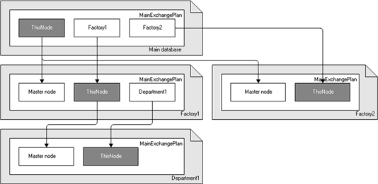
Fig. 480. Hierarchical distributed infobase
Configuration changes are allowed only in the root distributed infobase node with further distribution, along the hierarchy, from the root node to the subordinate node, and so on. The distributed infobase management mechanism ensures the same configuration in all distributed infobase nodes.
The data can be changed in any distributed infobase node. Data synchronization is provided by distributing data changes made in one node to the whole distributed infobase structure.
When organizing document sequences in a distributed infobase, consider that including a document in a sequence makes sense only in one distributed infobase node. This can be either a node where the document was generated or any other node, but there must be one node. Breaching this principle may result in various issues, for example, the inability to restore document sequences.
If the completely identical configurations are supported in the distributed infobase, the data must be completely identical. The content of data with changes sent within a distributed infobase can be regulated "vertically" (by defining the cluster of metadata objects containing data involved in the exchange) or "horizontally" (by setting conditions for sending and receiving changes at the level of individual data items).
15.3.2. Exchange plans
Exchange plans are in the heart of distributed infobase management. However, to consider the exchange plan eligible for organization of a distributed infobase, the Distributed infobase property must be set when configuring this exchange plan.
The distributed infobase data are transferred using messages provided by the message infrastructure. Unlike the universal data exchange features, the content of messages sent between distributed infobase nodes cannot be arbitrary and is regulated by the exchange protocol accepted for the distributed infobase.
The variety of data whose changes will be exchanged within the distributed infobase depends on the exchange plan. If a metadata object is included in the exchange plan, it indicates that changes to the data that corresponds to this metadata object can be registered for the nodes of this exchange plan. Unlike the universal data exchange features, the variety of data that can be exchanged within the distributed infobase is strictly limited by the content of the associated exchange plan.
To register data changes in the distributed infobase, the change registration service is used. The data items are placed in the message using the XML serialization mechanisms. Apart from data changes, configuration changes and some additional service information are sent between the distributed infobase nodes. Configuration changes are registered and transferred in the distributed infobase completely automatically, which is unavailable to the user and the configuration developer.
Unlike the universal data exchange features, generation and receipt of data exchange messages in a distributed infobase are performed "as one action", meaning that all the entire message is generated by calling one 1C:Enterprise language method. The reading of message content is also performed by calling one method. To control the content of data that is put in the message and read from the message to be put in the database, the event handlers can be set on the exchange plan module data items level:
-
OnSendDataToSlave
-
OnSendDataToMaster
-
OnReceiveDataFromSlave
-
OnReceiveDataFromMaster
Thus, almost all universal data exchange mechanisms are used in the distributed infobase, but there are additional features that are exclusive to the distributed infobase.
15.3.2.1. Master and subordinate nodes
As stated above, each distributed infobase node may have one master node and an arbitrary number of subordinate nodes (see fig. 480). For its master node, the node is subordinate. For its subordinate nodes, it is a master node. A node that does not have a master node is the distributed infobase root node.
Note. IMPORTANT. The distributed infobase root node is the only place where the infobase configuration can be changed.
The distributed infobase can be built based on several exchange plans with the set Distributed infobase property. Interaction in each "master – subordinate" pair happens in accordance with one of the exchange plans set in configuration. There are no restrictions for using exchange plans in distributed infobase nodes.
Each distributed infobase node, as with the universal data exchange features, "knows" only its neighbors, that is, the master and subordinate nodes. The complete scheme of distributed infobase is not known to any node if the scheme has more than two levels.
15.3.2.2. Resolving collisions
The standard procedure for resolving collisions in a distributed infobase is based on "master – subordinate" relationships. It is performed automatically when receiving a message. It is assumed that the data item change made in the master node has a higher priority than the change made in the subordinate node. Thus, if the message from a subordinate node contains a data item with changes registered for this subordinate node, no action will be taken, meaning that the data item will not be written in the database and the change registration record will not be deleted.
If the message from a master node contains a data item with changes registered for the master node, the data item will be written in the database and the change registration record will be deleted.
15.3.2.3. Initial image of a distributed infobase node
Usually, in a distributed infobase, a subordinate node is generated from the master node. It means that for the subordinate node specified in the exchange plan, a new infobase that corresponds to the subordinate node is created based on the configuration and data in the master mode. Such infobase is called the initial image of a distributed infobase node
When creating an initial image, the following actions are taken:
- The configuration is transferred from the master node to the initial image without changes.
The required extensions are transferred from the master node to the initial image. They are transferred if the extension support is enabled for the exchange plan used, and there are extensions that can be used in the distributed infobase.
-
The object nodes are created in the initial image exchange plan. They are initialized in a way that additional setting is not required to start exchanging data between the master node and the subordinate nodes.
-
The data is transferred from the master node to the initial image according to the rules set by the exchange plan (the content of the exchange plan and the result of the OnSendDataToSlave event handler).
The procedure for creating the initial image can be repeated for the same node. This makes sense when the infobase of the subordinate node was lost irrevocably. When creating the initial image, all change registration records of the node for which the initial image is created are deleted because it is assumed that the history of this subordinate node begins from the fresh start.
15.3.2.4. Data exchange message in a distributed infobase
To transfer data and configuration changes in a distributed infobase, data exchange messages are used, which are provided by the message infrastructure. In case of the universal data exchange features, the developer defines what goes into the message body and how, but in case of a distributed infobase, the structure and content of data stored in the message body are strictly defined.
Let's review the structure of a data exchange message used in a distributed infobase. Let's take the following message as an example:
<v8msg:Message>
<v8msg:Header>
<v8msg:ExchangePlan>RemoteWarehouses</v8msg:ExchangePlan>
<v8msg:To>Warehouse1</v8msg:To>
<v8msg:From>Office</v8msg:From>
<v8msg:MessageNo>20</v8msg:MessageNo>
<v8msg:ReceivedNo>15</v8msg:ReceivedNo>
</v8msg:Header>
<v8msg:Body>
<v8de:Changes>
<v8de:Signature>7b4d5320-f69c-4a7b-9273-ff56607fc8ab</v8de:Signature>
<v8de:Config>
<!--Changed
configuration objects -->
<v8de:Digest1>88d3f3a6ba3f4df03c7ec00f154837fc</v8de:Digest1>
<v8de:Digest2>00cf636b02a488103a64c7a2cf81069e</v8de:Digest2>
</v8de:Config>
<v8de:ConfigurationExtensions>
<ConfigurationExtensionDeletion>
<!--deleted
extension identifiers -->
</ConfigurationExtensionDeletion>
<v8de:ConfigurationExtension>
<!--Extension
data 1 -->
</v8de:ConfigurationExtension>
... <v8de:ConfigurationExtension>
<!--Extension
data N -->
</v8de:ConfigurationExtension>
</v8de:ConfigurationExtensions>
<v8de:Nodes>
<v8de:Node>
<!--Master
node data -->
</v8de:Node>
<v8de:Node>
<!--Subordinate
node data -->
</v8de:Node>
</v8de:Nodes>
<v8de:Data>
<!--Changed data
items -->
</v8de:Data>
</v8de:Changes>
</v8msg:Body>
</v8msg:Message>As you can see from the example, all features of the data exchange message used in the distributed infobase are in the message body. The message body (the Body element) contains a single XML element: Changes. This element contains all data sent during data exchange in a distributed infobase:
-
Changes may contain several nested items associated with the same namespace:
-
Signature contains "signature" of the exchange plan that was used to get the message.
-
Config contains configuration changes as well as the data identifying the configuration state.
-
Optional Metadata elements nested in Config contain changes of specific configuration objects. If the configuration changes are not sent in the message, the Metadata items are not present. Such items can only be included in messages sent from master node to the subordinate node. Digest1 and Digest2 items contain digital signatures of configuration changes and the whole configuration excluding changes, which both can be transferred in the message. Digest1 and Digest2 items are included in all messages sent from the master node to the subordinate node and vice versa.
-
The optional ConfigurationExtensions item contains information on the extensions that can be sent within distributed infobase. This item contains several nested ConfigurationExtension items and each of them describes one extension. Also, the ConfigurationExtensionDeletion item can be used as the subordinate that includes identifier of extension, which should be deleted in the receiving infobase of this message exchange.
-
Nodes can only be included in messages sent from a master node to a subordinate node. This element includes two nested Node elements. The first one contains the master node (sender) data, and the second one contains the subordinate node (recipient) data.
-
The Data item includes changed data items sent in the message. Data items are included in the message using the XML serialization.
15.3.2.5. Configuring exchange plans for distributed infobase operations
As noted above, to use an exchange plan to organize a distributed infobase, set the Distributed infobase property for this exchange plan.
When configuring the exchange plan used to organize the distributed infobase, define the exchange plan content is a must, because this content defines the variety of data used to keep the changes register and the data to be sent during the data exchange in the distributed infobase.
Note that if the exchange plan of the configuration that already uses distributed infobase includes another metadata object, this will not result in automated registration of changes in data item corresponding to this metadata object. Thus, if you include the new object in the exchange plan content and you need to transfer the existing data to other nodes, ensure this individually.
15.3.2.6. Exchange plan event handlers
When needed, the ExchangePlansObject.<Exchange plan name> object can have the following event handlers: OnSendDataToSlave, OnSendDataToMaster, OnReceiveDataFromSlave, and OnReceiveDataFromMaster. They allow you to manage placement of a data item in the message and reading a data item from the message.
The OnSendDataToSlave event handler is called when placing a data item in the message sent to the subordinate node of the distributed infobase. The first parameter contains the data item itself. The value of the second parameter when calling the handler is DataItemSend.Auto, but this value can be changed by the handler. If DataItemSend.Auto is still the second parameter value after the handler execution, this is the default behavior (the data item will be placed in the message). If the second parameter in the handler is set to DataItemSend.Delete, the message will include an object that corresponds to the data item deletion. For database objects, it is an object of the ObjectDeletion type initialized with a reference to the database object to be deleted. For record sets, it is an empty record set. The behavior corresponding to the DataItemSend.Delete value is the same as the behavior corresponding to the DataItemSend.Auto value only for a constant record manager. If the second parameter is set to DataItemSend.Ignore, the message will not include anything that corresponds to the current data item sent in the first parameter.
The OnSendDataToMaster event handler is only different from the previous one because it is called when the data item is transferred to the message sent to the master node.
The OnReceiveDataFromSlave handler is called after reading the data item from the message and before writing the item to the database. The first parameter includes the data item read from the message. The second parameter when calling the handler is set to DataItemReceive.Auto, which corresponds to the default behavior. This means that if no changes to the data item for the sending node are registered in this node, the item will be written to the database. If the changes are registered, the item will not be written to the database. The value of the second parameter can be changed by the handler. If the second parameter value is set to DataItemReceive.Accept, the data item will be written to the database, regardless of whether its changes are registered for the sending node. If the changes are registered, the change registration record is deleted. If the second parameter is set to DataItemReceive.Ignor, no action will be taken (the item will not be written to the database and no action with the change registration records will be taken). The third parameter allows you to manage data item change registration for the sending node. When calling the handler, this parameter value is set to False. If this value is not changed by the handler, no further action will be taken. If the parameter value is set to True in the handler, there will be no registration in case there are no registered changes of the data item for the sending node.
The OnReceiveDataFromMaster event handler has the same set of parameters as the previous handler. The difference is that this handler is called on reading a message from the master node of the distributed infobase. The actions taken when the data item is received differ too. The DataItemReceive.Auto and DataItemReceive.Accept values of the second parameter set by the handler have the same effect, because according to the accepted strategy for resolving collisions in the subordinate node, the data item read from the message must be written to the database, regardless of whether its changes are registered. In other aspect, the parameter values and the sense of actions taken are the same as described above.
15.3.3. Distributed infobase operations
15.3.3.1. General information
There are several aspects of distributed infobase operations:
-
Creating an initial image for a distributed infobase subordinate node.
-
Writing a data exchange message to be sent to another distributed infobase node.
-
Reading a data exchange message sent from another distributed infobase node.
If you need 1C:Enterprise language to access the universal data exchange features, you can take the described actions using 1C:Enterprise language or interactively with the More actions menu commands of the exchange plan list form, or by other means available during configuration.
Besides, you can set and retrieve the master node for each distributed infobase node. This operation cannot be considered the main operation of a distributed infobase. Therefore, there is no interactive action for it.
15.3.3.2. Distributed infobase operations using 1C:Enterprise language
15.3.3.2.1. Creating an initial image for a distributed infobase subordinate node
To create an initial image of a distributed infobase subordinate node, the ExchangePlansManager object has the CreateInitialImage() method.
The first parameter of this method must be passed as a value of the ExchangePlansLink.<Exchange plan name> type, which represents a link to the subordinate node of the distributed infobase, or a value of the ExchangePlansObject.<Exchange plan name> type, which represents this node.
The second parameter must contain the connection string identifying the infobase, where the initial image of the subordinate node will be located. The infobase used to create the initial image must not be empty or non-existent.
As noted above, the infobase configuration is transferred to the initial image without changes. The data corresponding to the metadata objects that are not included in the exchange plan will not be placed in the initial image. Besides, when data items are transferred to the initial image, the OnSendDataToSlave event handler is called for each data item. It means that the initial image includes the data that is supposed to get there according to the rules stipulated by the set exchange plan. The order in which data elements are processed is the same as when using the SelectChanges() method (see Recording data exchange messages).
In the exchange plan used to create the initial image, two nodes will be created and initialized in the initial image infobase. One node will be for the master node, and the other one will be for "this" node. Thus, the infobase of the subordinate node is ready to exchange data with the master node right after creating the initial image.
All operations for transferring data to the initial image are performed within one transaction of the master node database. This ensures consistency of data placed in the initial image. However, when the master node infobase data is changed a lot by other users, there might be conflicts between the transaction of the initial image creation and transactions of other users. In such cases, before creating the initial image, set the exclusive mode for the master node infobase.
Note. Note. Switching the infobase to exclusive mode does not automatically switch the MS SQL database to single-user mode.
15.3.3.2.2. Writing data exchange messages in distributed infobases
As shown above, the data exchange message of a distributed infobase is different from the general data exchange message because it has different message body content. The procedure for writing data exchange message of the distributed infobase is different from the general message writing in the similar way.
To write data exchange messages of a distributed infobase, the exchange plan manager uses the WriteChanges() method. An object of the ExchangeMessageWriter type used to write messages is passed to this method as the first parameter. The BeginWrite() method must be called for this object, but the EndWrite() method must not be called for this object yet.
The optional second parameter specifies the maximum number of data items to be placed in the message within a single transaction. If the parameter value is set to 0 (default value), the whole message generation will be performed within a single transaction. This option ensures the best consistency of data placed in the message, but conflicts with transactions performed by other users are possible. With fewer items processed within a single transaction, there is less chance of transaction conflicts. However, in this case, the chance of placing inconsistent data in the message is higher. Therefore, it is recommended that you do not use non-default values for the second parameter without urgent need.
The WriteChanges() method writes the Changes XML element into the data exchange message body by placing all the required information there, as shown above. The configuration objects and data items with changes registered for the message recipient node are placed in the message fragments. The actual placement of the data item in the message is defined by the result of the execution of the OnSendDataToMaster (OnSendDataToSlave) event handler called from the object of the ExchangePlansObject.<Exchange plan name> type that represents the message recipient node. The order in which changes are saved is the same as when using the SelectChanges() method (see Recording data exchange messages).
Below is a standard code snippet that writes a data exchange message of a distributed infobase.
XMLWriter = New XMLWriter();
XMLWriter.OpenFile(MessageFileName);
Node = ExchangePlans.RemoteWarehouses.FindByCode(NodeCode);
MessageWriter = ExchangePlans.CreateMessageWriter();
MessageWriter.BeginWrite(XMLWriter, Node);
ExchangePlans.WriteChanges(MessageWriter);
MessageWriter.EndWrite();15.3.3.2.3. Reading data exchange messages in distributed infobases
To read the body of a data exchange message of a distributed infobase, the exchange plan manager uses the ReadChanges() method.
An object of the ExchangeMessageReader type used to read a message in general is passed as the first method parameter. The BeginRead() method must be called for this object, but the EndRead() object must not be called for this object.
Note. Tip. When calling the BeginRead() method of the ExchangeMessageReader object, it is strongly recommended that you do not set the second parameter value, or set the default value: AllowedMessageNo.Greater.
The reason is that the whole data exchange logic of a distributed infobase considers that data exchange messages might be lost, but the same message is not allowed to be received again.
The value of the optional second parameter can be set to the maximum number of data items read from messages and placed in the database within a single transaction. The default parameter value is 0. It means that the entire message is read within a single transaction. If the entire message is read within a single transaction, then in case of errors, the data items cannot be read and placed in the database partially. However, in this mode, the number of database changes to be made within a single transaction might be too large. Besides, the likelihood of conflict between transactions with message reading and transactions performed by other users is higher. To avoid such issues, you can limit the number of data items processed in a single transaction. If there is no urgent need, we recommend that you use the default mode, that is, read all data items in a single transaction.
The sequence of actions taken by the ReadChanges() method:
-
The exchange plan "signature" is read and verified to ensure that the message comes from the expected exchange plan of the expected configuration.
-
The configuration changes are read from the message. When reading, the digital configuration signatures are verified to ensure compatibility of configurations in the sending and current distributed infobase nodes. For each of the configuration changes read, it is checked whether the configuration object is actually changed. Remember that the changed configuration objects can be included in the messages sent from the master node to the subordinate node.
-
Change registration records of objects and data items sent in the messages with the receipt confirmation are deleted. Remember that the maximum number received by the message sending node is included in the message header and is available via the ReceivedNo property of the ExchangeMessageReader object.
-
If the configuration in the current distributed infobase node is different from the configuration of the sending node and it becomes apparent, there are two options:
-
If the current node is a master node to the sending one, this message cannot be further received under any circumstances.
-
If the current node is subordinate to the sending node, then before continuing to receive the message, update the database configuration to align it with the sending node configuration. When the database configuration is updated, previously received, saved, and modified configuration objects will be transferred to the database. Next, in both cases, an exception is thrown with the error message. In the first case, the message can be read. In the second case, this message can be read and received after updating the database configuration in the Designer mode.
-
-
When receiving a data exchange message sent from the master node of the distributed infobase, the data of the current node and the sending node are aligned with the data about these nodes contained in the data exchange message. If the data exchange message is received from the subordinate node, then there should be no such data there (for details, see Data exchange message in a distributed infobase).
-
The data items are read from the message and written to the database. The message can only contain data items that correspond to the metadata objects included in the exchange plan associated with this message. For each data item read from the message for an object of the ExchangePlansObject.<Exchange plan name> type, the OnReceiveDataFromMaster (OnReceiveDataFromSlave) event handler is called. Further actions for each data item depend on the result of the handler actions (for details, see Exchange plan event handlers).
15.3.3.2.4. Getting and setting a distributed infobase master node
The distributed infobase root node lacks a master node. All other nodes have a master node. In a standard distributed infobase scenario, you do not need to force the master node setting. However, in some cases, this may come in handy. For example, you may need to separate a subtree of the distributed infobase into an independent infobase or reassign a distributed infobase node.
To set the distributed infobase master node, use the SetMasterNode() method of the ExchangePlansManager object. The method has one parameter. If the value of the ExchangePlansObject.<Exchange plan name> or ExchangePlansLink.<Exchange plan name> type is passed to this method as a parameter, the exchange plan associated with the link of object must have the Distributed infobase property set. In this case, the master node will be set for this infobase. If Undefined is passed as the parameter value, the master node as the parameter value is canceled.
To execute this method successfully, there must be no active infobase users, including the Designer mode.
To get the master node, use the MasterNode() method of the ExchangePlansManager object. If the current infobase is not a distributed infobase node or the master node is not defined for it (it is a root node), the method returns Undefined. If the master node is set for the infobase, the method returns a value of the ExchangePlansLink.<Exchange plan name> type.
Note. Note. To cancel the assignment of the infobase master node, use the /ResetMasterNode parameter of the Designer batch mode command line.
If predefined data is used in a distributed infobase, operations with the master node are different:
-
Disconnecting an infobase from a distributed infobase:
-
For infobases used in 1C:Enterprise versions from 8.3.3 to 8.3.5 (regardless of the compatibility mode), call the SetPredefinedDataInitialization(True) method for all configuration objects for which the predefined items are created in Designer, and the Update predefined data property is set to Auto.
-
Disable the infobase by calling theSetMasterNode(Undefined) method or using the /ResetMasterNode parameter of the Designer batch mode command line.
-
-
Restoring a configuration in a distributed infobase node:
-
Set the update mode of predefined infobase data to PredefinedDataUpdate.DontAutoUpdate. To do this, use theSetInfoBasePredefinedDataUpdate() language method or the /SetPredefinedDataUpdate -DoNotUpdateAutomatically parameter of the Designer batch mode command line.
-
Get a link to the infobase master node using the MasterNode() method and remember the link.
-
Disable the infobase by calling the SetMasterNode(Undefined) method or using the /ResetMasterNode parameter of the Designer batch mode command line.
-
Restore the configuration and perform other operations to restore the node performance.
-
Restore the link to the master node using the SetMasterNode() method and specify the link to the node that was previously set as the master node (obtained in Step 2), as a parameter.
-
Set the update mode of predefined infobase data to PredefinedDataUpdate.Auto. To do this, use the SetInfoBasePredefinedDataUpdate() language method or the /SetPredefinedDataUpdate
-
-
Auto parameter of the Designer batch mode command line.
15.3.3.2.5. Getting information on the exchange message
When data exchange is performed automatically, it is important to understand what is inside the exchange message to import. To do that, use the ReadChangesDescription() method of the exchange plan manager. After calling the method, you cannot continue reading the exchange message. The method returns the ConfigurationChangesDescriptionInExchangeMessage type object, which you can use to get the following information:
-
ConfigurationChanged. This property is set to True if the exchange message contains a configuration update, and reading this message will require to update the infobase configuration.
-
ConfigurationExtensionsChanged. This property will be set to True if any extension is changed or one or more extensions are added, deleted, or excluded from the distributed infobase.
-
ChangedConfigurationExtensionsMetadataModifiesDataStructure. The property is set to True if the extensions that will be changed, added, or deleted when reading the exchange message in exclusive mode will change the metadata structure of this infobase.
You can also use the ReadConfigurationAndConfigurationExtensionsChanges() method of the data exchange manager to read the description of the exchange message. The key difference between this method and the ReadChangesDescription() method is that after applying this method, you can continue reading the exchange message. You can continue reading if the ReadConfigurationAndConfigurationExtensionsChanges() method call did not result in an exceptional situation or configuration/extension metadata changes.
An analysis of exchange message contents may look as follows:
XMLReader = New XMLReader;
XMLReader.OpenFile(FileName);
// Start reading the
message
MessageReader = ExchangePlans.CreateMessageReader();
MessageReader.BeginRead(XMLReader);
// Read the description
of exchange message changes
ChangesDescription = ExchangePlans.ReadConfigurationAndConfigurationExtensionsChanges(MessageReader);
// Process metadata
changes
If ChangesDescription.ConfigurationChanged Then
// The message has a configuration change
Raise "ConfigurationUpdateRequired";
ElsIf ChangesDescription.ConfigurationExtensionsChanged Then
// The message has changed extensions.
Raise "RestartRequired";
ElsIf ChangesDescription.ChangedConfigurationExtensionsMetadataModifiesDataStructure Then
//
Configuration extensions require metadata changes
SetExclusiveMode(True);
EndIf;
// Read the exchange
message
ExchangePlans.ReadChanges(MessageReader);
// Finish reading the
message
MessageReader.EndRead();
XMLReader.Close();15.3.3.3. Interactive distributed infobase operations
As noted above, a number of most frequently performed actions with a distributed infobase can be performed interactively with the More (All actions) menu of the exchange plan list form (or the list form icon on the command bar). The commands are inserted into the menu on automated filling.
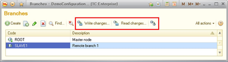
Fig. 481. Exchange plan list
To execute these commands, choose the exchange plan node for which you want to execute the command, and then select the required item from the More (Actions) menu.
To create an initial image of the distributed infobase subordinate node, click More actions – Create initial image… (All actions – Create initial image…). After clicking this menu item, a dialog box will appear that will prompt you to select the infobase location type and its parameters (when creating an image in client/server mode). After clicking Create initial image in this dialog box, the initial image creation will be started. The procedure for creating an initial image interactively is the same as when you call the CreateInitialImage() method of the ExchangePlansManager object.
To write data exchange messages to a file, click More actions – Write changes… (All actions – Write changes…). A dialog box appears after clicking this menu item. Here, specify the number of data items processed in a single transaction. Then click Write and save to file This opens an exchange file selection dialog box. After choosing, click Open, and the data upload will begin.
To read data exchange messages from a file, click More actions – Read changes… (All actions – Read changes…). A dialog box appears after clicking this menu item. Here, specify the number of data items processed in a single transaction. Then click Select a file and read changes. This opens an exchange file selection dialog box. After choosing, click Open, and the data will start loading.
All data loading/unloading operations (including initial infobase image creation) are performed on the 1C:Enterprise server side.
15.3.4. Scenarios of data exchange in distributed infobases
The OnSendDataToSlave, OnSendDataToMaster, OnReceiveDataFromSlave, and OnReceiveDataFromMaster event handlers ensure flexible management of data exchange in the distributed infobase. A large number of data exchange scenarios can be built using these handlers. This section describes several sample scenarios.
15.3.4.1. Default behavior
This scenario is the simplest one and corresponds to the default distributed infobase behavior. There are several aspects of this scenario:
-
Each data item change made in any distributed infobase node tries to distribute itself to all nodes.
-
Collisions are resolved based on the "master – subordinate" node relations.
To implement such scenario, all handlers must not change the values of the parameter passed to them. The handlers can also be not set at all.
15.3.4.2. Data distribution between subordinate nodes
This scenario assumes that for some data items for which it is implemented the following is true:
-
All data items are in the master node.
-
The presence of a data item in a subordinate node is defined by comparing the values of some data item attributes with the attributes of the exchange plan subordinate node.
-
Collisions are resolved based on the "master – subordinate" node relations.
To implement this scenario, ensure that when writing a data exchange message in the master node, the message does not include data items that should not be in the subordinate node.
Besides, if the data item attribute values can be changed in the subordinate node, ensure that when a data exchange message is received in the master node, changes are registered for objects that should not be in the subordinate node according to the values of their attributes.
To dig deeper into this example, let's suppose that we use the Invoice document as a type of data items for which the scenario is implemented. This document has the Warehouse attribute of the CatalogRef.Warehouses type. The data exchange is organized in accordance with the Warehouses exchange plan. This exchange plan also has the Warehouse attribute of the CatalogRef.Warehouses type specified. The exchange plan is used to organize a distributed infobase, in which the root node is the central office, and the subordinate nodes are warehouses. For each subordinate node of the exchange plan, the Warehouse attribute is set to indicate which warehouse corresponds to this node. All Invoice documents must be present in the root node, and the condition for documents presence in the subordinate nodes is the equality of the Warehouse attribute values in the document and the exchange plan node.
In this case, to ensure that the Invoice documents do not get into the subordinate nodes where they should not get, the OnSendDataToSlave event handler must look as follows:
Procedure OnSendDataToSlave(DataItem, ItemSend)
DataType = TypeOf(DataItem);
If DataType = Type("DocumentObject.Invoice") Then
If DataItem.Warehouse
<> Warehouse Then
ItemSend = DataItemSend.Delete;
EndIf;
EndIf;
EndProcedureIn the sample handler, the data type is analyzed. If it is equal to DocumentObject.Invoice, the value of the Warehouse attribute of the document is compared with the value of the Warehouse attribute of the exchange plan node. If the attribute values are equal, the ItemSend parameter value can stay unchanged (when calling, the parameter is set to DataItemSend.Auto). The XML presentation of the document will be included in the message. If the attribute values are not equal, the ItemSend parameter is set to DataItemSend.Delete. In this case, the message will include an XML presentation of the ObjectDeletion object initialized with a link to the Invoice document.
In may seem strange that if the Warehouse attribute values are not equal, the ItemSend parameter is set to DataItemSend.Delete, not DataItemSend.Ignore, because in case of the DataItemSend.Delete value, the XML presentation of the ObjectDeletion object will be placed in the messages sent to all subordinate node, except the node to which the document itself will be sent. Thus, in many cases, the ObjectDeletion object will be sent to the nodes that never contained the document that has to be deleted.
This is true, but in this example we review the most common case. If it is known that the value of the Warehouse attribute of the Invoice document can only be set when the document is created and cannot be changed later, then the ItemSend parameter in this handler could indeed be set to DataItemSend.Ignore.
If the value of the Warehouse attribute of the Invoice document can be changed in the subordinate node, then the OnReceiveDataFromSlave event handler must be specified in the exchange plan. This even handler must look as follows:
Procedure OnReceiveDataFromSlave(DataItem, ItemReceive, SendBack)
DataType = TypeOf(DataItem);
If DataType = Type("DocumentObject.Invoice") Then
If DataItem.Warehouse
<> Warehouse Then
SendBack = True;
EndIf;
EndIf;
EndProcedureIn the sample handler, the data type is analyzed. If it is equal to DocumentObject.Invoice, the value of the Warehouse attribute of the document is compared with the value of the Warehouse attribute of the exchange plan node. If the attribute values are equal, then the values of ItemReceive and SendBack parameters can stay the same. This will ensure the default behavior when receiving a data item. If the attribute values are note equal, the SendBack parameter is set to True. This ensures that document changes will be registered and, when sending messages to the subordinate node, the ObjectDeletion object will be sent, unless the Warehouse document attribute is changed in the master node in a way so that it is equal to the value of the Warehouse attribute of the corresponding exchange plan node.
If the value of the Warehouse attribute of the Invoice document cannot be changed after creating the document, the OnReceiveDataFromSlave handler can be omitted.
15.3.4.3. Custom collision resolution
This scenario assumes that for some data items for which it is implemented the following is true:
-
Each data item change made in any distributed infobase node tries to distribute itself to all nodes.
-
Collisions are resolved based on the "master – subordinate" relationship, but the subordinate node has a higher priority.
To review this case, let's use the above example with the Invoice document and the Warehouses exchange plan.
In this case, the OnReceiveDataFromSlave and OnReceiveDataFromMaster event handlers must be specified. The OnReceiveDataFromSlave handler will look as follows:
Procedure OnReceiveDataFromSlave(DataItem, ItemReceive, SendBack)
DataType = TypeOf(DataItem);
If DataType = Type("DocumentObject.Invoice") Then
ItemReceive = DataItemReceive.Accept;
EndIf;
EndProcedureThis handler is quite simple. First, the data item type is verified. If it is the one you need, the ItemReceive parameter is set to DataItemReceive.Accept. In this case, the data item will be accepted, regardless of whether its changes are registered.
The OnReceiveDataFromMaster event handler looks as follows:
Procedure OnReceiveDataFromMaster(DataItem, ItemReceive, SendBack)
DataType = TypeOf(DataItem);
If DataType = Type("DocumentObject.Invoice") Then
If ExchangePlans.IsChangeRecorded(Link,DataItem) Then
ItemReceive = DataItemReceive.Ignore;
EndIf;
EndIf;
EndProcedureThis handler is more complex. If the data item has the required type, it is checked whether data item changes are registered for the node that sent the message. If the changes are registered, the ItemReceive parameter value is set to DataItemReceive.Ignore. As a result, the data item read is not written to the database, and the change registration is saved, which allows the data item to be placed in the message sent to the master node.
15.3.4.4. Other scenarios
These are some of the possible scenarios for organizing data exchange in a distributed infobase. You can use the above handlers to implement various scenarios. Some of them may combine the above scenarios, and some may be completely different.
Chapter 16. Operations with various data formats
16.1. XDTO tool
16.1.1. General information
The XDTO functionality is a versatile way of presenting data for interacting with various external data sources and software systems.
XDTO means XML Data Transfer Objects.
The XDTO mechanism allows you to create data presentation model (types and values model), which will provide an ability to easily change data in 1C:Enterprise and is well adapted to convert data from one formats to others, mainly XML, in a transparent way.
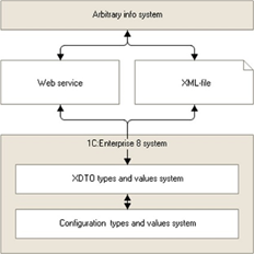
Fig. 482. General structure of XDTO
There are several tasks that XDTO mechanism performs:
-
Data exchange between 1C:Enterprise configurations with different ER diagrams.
-
Data exchange based on XML schemas that are not linked to configurations (for example, exchange with third-party information systems).
-
Operations with Web services. XDTO mechanism allows you to describe types of parameters and return values of Web services and to manipulate data that is sent and returned.
Key XDTO mechanism features:
-
Enables operations with XML.
-
Provides a standard data operation model.
Currently, data exchange with various platforms and systems is implemented via XML: XML documents are used to present data and the XML schema is used to describe data formats and structures. The XDTO mechanism allows you to create XML schemas required for exchange and format XML documents that satisfy these schemas.
At the same time, the XDTO mechanism allows you to perform these actions in a way that most 1C:Enterprise developers know.
The developers deal with data types and objects, data items contain properties, the values are set for the properties and so on. When manipulating data using the XDTO, the developer is, at the most, free of details associated with the way these data are presented in the XML. Obviously, you cannot eliminate these details completely, but they only appear where it is actually required.
16.1.2. XDTO factory
16.1.2.1. General information
The key concept of XDTO mechanism is the XDTO factory. The XDTO factory contains a description of all types operated by the system. In particular, each 1C:Enterprise configuration has a global XDTO factory, which writes all types used in the configuration in XDTO terms. This XDTO factory is available using the XDTOFactory global context property.
All types descriptions, included in the XDTO factory, are grouped in one or several XDTO packages. When comparing XDTO and XML, you can say that XDTO package is similar to XML schema. So, the XDTO factory may correspond to several XML schemas.
The XDTO factory is completely self-sufficient. It means that each type registered in XDTO factory can only refer to the types from this XDTO factory.
In general, the XDTO factory is created once based on the description of all types that must be registered in the factory. To create the XDTO factory using 1C:Enterprise language, use the XDTOFactory object wizard, which receives a set of XML schemas contained in the XMLSchemaSet object. A scenario where XDTO types are added to the factory one by one or in groups is not supported.
As opposed to the arbitrary XDTO factory, which can be created by the developer, the global XDTO factory is created automatically by the system when the new infobase is created and it allows adding XDTO types one by one or in groups. The visual construction means are used for this, which allow you to add XDTO packages in the General XDTO packages branch of the metadata tree. All packages in the global XDTO factory can be divided into three types:
-
A single XDTO package containing the platform type description. This package is the same for all 1C:Enterprise configurations.
-
A single XDTO package containing the description of configuration types created after editing the metadata (creating and changing properties of catalogs, documents, and so on).
-
One or several XDTO packages described directly in the General XDTO packages branch of the configuration object tree.
The XDTO package contains the description of some types belonging to a namespace, which is a package namespace. Besides type descriptions, the XDTO package can contain links to packages used by this package and a list of global package property definitions.
Links to other packages are contained in the Dependencies property of the XDTO package. It is the XDTOPackageCollection object. The packages of this collection include types from the namespace, for which there are links in this package.
The package may include links to global properties from other packages.
The loops in XSD schemas importing and including directives are not supported.
16.1.2.2. Retrieving XDTO factories from XSD schema files
Below is the example of XDTO factory creation based on the XML schema from the XML file. Since the XDTO mechanism is an abstraction built "above" the XML, you need to "go through" several levels of XML data operations to retrieve the XML schema from an XML file:
-
First, low-level reading/writing of XML files.
-
Then the XML object model from which you can receive the XMLSchema 1C:Enterprise language object with XML schema data.
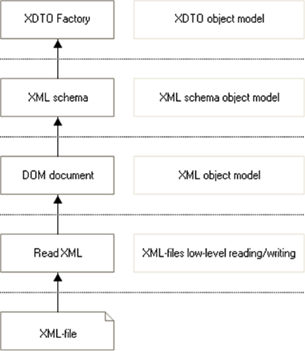
Fig. 483. Creating XDTO factory
Example:
// Create an XDTO
factory based on the XML schema
// from the XML file
// Create a default XML
reading object
XMLReader = New XMLReader;
// Open the XML file
ReadXML.OpenFile("c:/temp/my_schema.xsd");
// Create a default DOM
document builder
DOMBuilder = New DOMBuilder;
// Read the XML file
into the DOM document
DOMDocument = DOMBuilder.Read(XMLReader);
// Create a default XML
schema builder
XMLSchemaBuilder = New XMLSchemaBuilder;
// Receive the XML
schema from the DOM document
XMLSchema = XMLSchemaBuilder.CreateXMLSchema(DOMDocument);
// Create a set of
default XML schemas
XMLSchemaSet = New XMLSchemaSet;
// Add the XML schema
to the XML schema set
XMLSchemaSet.Add(XMLSchema);
// Create XDTO factory
based on the XML schemas set
NewXDTOFactory = New XDTOFactory(XMLSchemaSet);In the example above, the ReadXML object is created and then the XML file located on the disk is opened. After this, the DOM document builder is used to create the DOMDocument object containing XML file data. Then the XML schema builder uses the DOM document as a basis to create the new XMLSchema object containing XML scheme data. Finally, the empty set of XML schemas is created where the existing XML schema is included and the XDTO factory is created based on this set.
16.1.2.3. Retrieving XDTO factories from multiple sources
In some cases, you might need to create a factory based on several schemas. Some of them might be provided as a file and some need to be "inherited" from other XDTO factories (including the global factory).
Schemas = New Array;
Schemas.Add("c:/temp/schema
1.xsd");
Schemas.Add("c:/temp/schema
2.xsd");
Packages = New Array;
Packages.Add(XDTOFactory.Packages.Get("Package
1 URI"));
Packages.Add(XDTOFactory.Packages.Get("Package
2 URI"));
MyFactory = CreateXDTOFactory(Schemas, Packages);In this example, the XDTO factory is created based on 4 sources:
-
XML schema located in the c:/temp/schema 1.xsd file.
-
XML schema located in the c:/temp/schema 2.xsd file.
-
Schemas from package 1 of the current configuration.
-
Schemas from package 2 of the current configuration.
In general, it is not required to retrieve packages from the global XDTO factory. This can be a custom factory.
16.1.2.4. Retrieving XDTO factory from XDTO data object
When you create an XDTO object column, use the same XDTO factory instance. You cannot use XDTO values or objects that are created by different factories. To get an XDTO factory instance of any XDTO value, use the Factory() method of the XDTODataObject or XDTODataValue object.
Incorrect example:
URI = "http://v8.1c.ru/8.1/data/enterprise/current-config";
RefType = XDTOFactory.Type(URI, "CatalogRef.Counterparties");
CounterpartyRef = XDTOFactory.Create(RefType, RefToCatalogItem);
…
ServiceDefinition = WSReferences.WSRef1.GetWSDefinitions();
ServiceFactory = ServiceDefinition.XDTOFactory;
ObjectType = ServiceFactory.Type(URI, "DocumentObject.Invoice");
DocumentObject = ServiceFactory.Create(ObjectType);
DocumentObject.Counterparty
= CounterpartyRef; // ERROR!Correct example:
URI = "http://v8.1c.ru/8.1/data/enterprise/current-config";
ServiceDefinition = WSReferences.WSRef1.GetWSDefinitions();
RefType = ServiceDefinition.XDTOFactory.Type(URI, "CatalogRef.Counterparty");
CounterpartyRef = ServiceDefinition.XDTOFactory.Create(RefType, RefToCatalogItem);
…
FactoryRefs = CounterpartyRef.Factory();
ObjectType = FactoryRefs.Type(URI, "DocumentObject.Invoice");
DocumentObject = FactoryRefs.Create(ObjectType);
DocumentObject.Counterparty
= CounterpartyRef; // CORRECTIn the correct example, the ServiceDefinition.XDTOFactory property and the CounterpartyRef.Factory() function return the same factory instance.
See also:
-
XDTO value (see XDTO value).
-
XDTO object (see XDTO object).
16.1.3. XDTO data types
16.1.3.1. General information
Each type of XDTO data is either a XDTO value type or XDTO object type. So, to describe a value type, use the XDTOValueType object. To describe an object type, use the XDTOObjectType object.
The XDTOValueType object is used to describe types of simple indivisible values, which cannot be divided into parts. These are, for example, various strings, numbers, date and so on.
The XDTOObjectType object is used to describe to types of data instances that have a state presented as a set of this data instance property values. The property types of this data instance can be both XDTO value types and XDTO object types.
The XDTOValueType and XDTOObjectType has the same properties:
-
Name. Type name.
-
NamespaceURI. URI of the namespace where this type is defined.
Value of these properties correspond to the similar parameters identified for the type in the XML schema. The type name and namespace URI create a unique type identifier. The type name must be set. The NamespaceURI property may contain an empty string although this is undesirable.
16.1.3.2. XDTO value type
According to the rules for simple type from an XML schema, you can define an XDTO value type using the following ways:
-
By limiting when you set a base type (the BaseType property) and a set of limits for the set of possible values (the Facets property).
-
By merging when the type is the result of merging several value types. The merged types are listed in the MemberTypes property.
-
By a list when the value is a list of values. Set a value type of items included in the value list in the ListItemType property.
Besides the Name and NamespaceURI properties, the XDTO value type contains the following properties:
-
BaseType. Base type for this XDTO value type. Base type can be inherited but only from other types of XDTO values. The acceptable set of values of the inherited type is the subset of possible base value set. The upper level of the simple types hierarchy is the predefined anySimpleType type from http://www.w3.org/2001/XMLSchema namespace. All value types are directly or indirectly inherited from this type. The types created by merging or by the list are always directly inherited from anySimpleType.
-
Facets. A list of facets limiting the set of possible values against the base type. The list of facets is only set for XDTO value types that are defined by limiting the base type. Each facet is a pair: a facet name and a value. The list of possible facet names is defined. Not all available facets can be applied to the type. The list of facets and their applicability to some type are defined by the XML Schema rules (http://www.w3.org/TR/xmlschema-2/).
-
MemberTypes. A list of types that constitute the merging. Only XDTO value types can be merged. If the type is created by merging, the MemberTypes list includes at least one type. The Facets list must be empty and the ListItemType property must retrieve an undefined value.
-
ListItemType. When an XDTO value type is defined by a list, this property shows a list item type. In this case, the Facets and MemberTypes lists must be empty.
-
The list of available facets names (defined by the XDTOFacetType system enumeration):
-
Length. Length facet. Contains a number of length units. The length unit has different meaning for different types. For the string and anyURI types, the length includes the number of characters. For the hexBinary and base64Binary types, the length includes the number of binary data bytes. For the types defined by the list, the length includes the number of list items.
-
MaxInclusive. A facet of the maximum including the limit. Limits the value space of this type with the maximum value. Any value of this type is less or equal to the specified value.
-
MaxLength. A facet of the maximum length. Includes the maximum number of length units. The length unit has different meaning for different types. For the string type, the maximum length includes the maximum number of characters. For the hexBinary and base64Binary types, the maximum length includes the maximum number of binary data bytes. For the types defined by the list, the maximum length includes the maximum number of list items.
-
MaxExclusive. A facet of the maximum excluding the limit. Limits the value space of this type with the maximum value. Any value of this type is less than the specified value.
-
MinInclusive. A facet of the minimum including the limit. Limits the value space of this type with the minimum value. Any value of this type is larger or equal to the specified value.
-
MinLength. A facet of the minimum length. Includes the minimum number of length units. The length unit has different meaning for different types. For the string type, the minimum length includes the minimum number of characters. For the hexBinary and base64Binary types, the minimum length includes the minimum number of binary data bytes. For the types defined by the list, the minimum length includes the minimum number of list items.
-
MinExclusive. A facet of the minimum excluding the limit. Limits the value space of this type with the minimum value. Any value of this type is larger than the specified value.
-
Pattern. A pattern facet. Includes regular expression that defines the value space of this type.
-
Enumeration. An enumeration facet. Defines the set of acceptable values for this type.
-
SpaceCharacters. A space character facet. It can take the following three values:
-
Save. A string can contain any space characters.
-
Replace. A string cannot contain #x9 (TAB), #xA (linefeed), and #xD (carriage return). If they are present, they must be replaced with #x20 character (space).
-
Collapse. In addition to the requirements for the replace value, a string cannot contain #x20 (space) double characters and leading or closing #x20 (space) characters.
-
-
TotalDigits. A facet of the total number of digits. Includes the total number of digits (both integer and fractional part).
-
FractionDigits. A facet of the number of fraction digits. Includes the number of digits in the fractional part of the number.
-
The XDTO infrastructure defines a set of predefined XDTO value types. This set matches a set of primitive types defined in XML Schema Part 2: Datatypes. Predefined types create a hierarchy in accordance with XML Schema Part 2: Datatypes. Type names correspond to type names in XML Schema and belong to the namespace URI: http://www.w3.org/2001/XMLSchema. The predefined types are automatically registered in any XDTO factory.
16.1.3.3. XDTO object type
Besides the Name and NamespaceURI properties, an XDTO object type includes the following properties:
-
BaseType. A base type for this type. This may be an XDTO object type only. Th base type in XDTO object hierarchy is the predefined anyType type from http://www.w3.org/2001/XMLSchema namespace. All XDTO object types are inherited from this type directly or indirectly.
-
Open. Indicates whether the XDTO object type is open. This property indicates whether an instance of an XDTO object can contain additional properties that are not defined in its type, meaning it implements the open content model. It corresponds to appearance of the following descriptions in the XML schema for this type: <anyAttribute> and <any>.
-
Abstract. Indicates whether the XDTO object type is abstract. It corresponds to appearance of the abstract="true" attribute item in the schema.
-
Ordered. Indicates whether the order of property value items matches the order of XDTO object type properties. If the xsd:all content model i set then the order of XML elements can be arbitrary. The acceptable order corresponds to the order of properties in the type. If the Ordered property is False, the sequence of XML elements is not controlled at the input and is determined by the property sequence at the output unless the Sequenced flag is True.
-
Sequenced. Indicates whether the instance of the respective XDTO object contains the XDTO sequence. This flag is True when the order of nested XML elements cannot be unambiguously defined by order of properties in the type (for example, in XML schema the content is set as <sequence … maxOccurs=10 … >) or the mixed="true" attribute is set for the XML type in the schema. The XDTO sequence allows you to explicitly define the sequence of the items as they appear in the XML document. For objects of types where the Serial property is False, the sequence of nested elements corresponds to the sequence of properties.
-
Mixed. Indicates whether mixed content for this type is defined in the XML schema. If the Mixed property is True, then the Sequenced value must be True as you cannot model mixed content without using the XDTO sequence.
-
Properties. A list of properties defined for this XDTO object type. Each property is presented as an instance of the XDTOProperty object. The list includes all properties, including properties defined in the base type.
There is a predefined XDTO object type called anyType and http://www.w3.org/2001/XMLSchema namespace URI. This is a base type for each XDTO object type but it does not have a base type. It is open, not abstract. It implies that there is a sequence and has an blank property list.
This XDTO object type matches the anyType type defined in XML Schema Part 2: Datatypes.
16.1.3.4. XDTO property
A specific property of a specific XDTO object is described using the XDTOProperty object. This means that the same instance of the XDTOProperty object cannot be used to describe properties in different XDTO object types and two different properties of one XDTO object type.
The XDTOProperty object has the following properties:
- Name. Property name. Within the XDTO object of the same type, property names must be unique.
When generating the XDTO data model based on the XSD schema, the names of XDTO properties are based on the attributes and items names described in the schema. The model is built sequentially. At first, the list of values is created based on the attributes and then based on the items, in the order they are presented in the schema.
The name is aligned to 1C:Enterprise language naming rules. Characters acceptable in an XML name (for example, a point "." or a hyphen "-") but unacceptable for 1C:Enterprise language are replaced with an underscore "_". In case of attribute and item name doubling, the duplicate is assigned with a name extended by the numeric suffix (starting with 1).
-
Type. Property type. It can be both an instance of the XDTOValueType object and an instance of the XDTOObjectType object.
-
UpperBound. An XDTO object type property can be defined as containing one or multiple values. A property is considered to contain one value if it equals one. If the UpperBound property is greater than one, it is considered that it can contain multiple values. Such property is modeled as a list in the object structure. Note that it is not a list in an XDTO value type description. The UpperBound property indicates the maximum number of property values. A value greater than one can be set only for properties that are presented as an XML element. The UpperBound property corresponds to the xsd:maxOccurs attribute in XML Schema. The –1 value corresponds to unbounded.
-
LowerBound. The minimum number of property values. The minimum number of property values can be less or equal to 0. The LowerBound value must be less than or equal to the UpperBound value, unless the UpperBound value is equal to –1.
-
Nillable. Indicates whether the property can have an undefined value. An undefined property value is presented in XML as an element that looks as follows: <elem xsi:nil="true" />. So, the Nillable property that is set to True can only be defined for properties with the Element presentation form. The Nillable property corresponds to the xsd:nillable attribute in the XML Schema. If the UpperBound property value is greater than one, an undefined value is valid for a property value list item.
-
DefaultValue. A default property value. The only possible default value is XDTODataValue. This property must be of the same type as the type of the property or of the inherited type. When creating an XDTO object, the property is set to the default value if it can have only one value. The IsSet() method of the XDTO object returns False for this property. For properties with multiple values, the list of values is initially empty, regardless of whether the default value is defined or not.
-
Fixed. Indicates whether the property value is fixed. If set to True, the fixed value itself can be retrieved through the DefaultValue property.
-
Form. Property presentation form in XML. This can be Text, Item, or Attribute. If the presentation form is Attribute or Text, the value of the UpperBound property cannot be greater than one. If the property is set to Text, the LowerBound property value must be equal to one as well. One type contains only one property that can have the Text presentation form. The other properties must have the Attribute presentation form.
-
LocalName. A local name of an attribute or an element used to present a property. For properties with the Text presentation form, it is an empty string.
-
NamespaceURI. A namespace URI for an attribute or an element used to present a property. It is an empty string if there is no namespace.
16.1.4. XDTO data instances
XDTO data instances can be XDTO values (XDTODataValue) or XDTO objects (XDTODataObject).
16.1.4.1. XDTO value
XDTO values are simple indivisible values in which separate parts cannot be identified. These are, for example, various strings, numbers, date and so on. Instances of simple values are immutable.
A new XDTO value can be created using the Create() method of the XDTO factory:
-
Based on an XDTO value type and value.
-
Based on an XDTO value type and lexical value presentation.
Below you can see examples of how to create an XDTO value.
Example:
GlobalXDTOFactory = XDTOFactory;
// Create an XDTO value
from the link
CatalogItemRef = Catalogs.Products.FindByCode("0000001");
XDTOValueTypeOfValueToCreate
= GlobalXDTOFactory.Type("urn:schemas v8 1c ru:config data", "CatalogRef.Products")
NewXDTOValue = GlobalXDTOFactory.Create(XDTOValueTypeOfValueToCreate, RefToCatalogItem);
// Create an XDTO value
from the lexical value presentation
XDTOValueTypeOfValueToCreate
= GlobalXDTOFactory.Type("http://www.w3.org/2001/XMLSchema", "dateTime");
NewXDTOValue = GlobalXDTOFactory.Create(XDTOValueTypeOfValueToCreate, "2006-04-20T12:00:30");The new XDTO value can also be created by reading the XML file.
Example:
GlobalXDTOFactory = XDTOFactory;
// Read XDTO value data
from the XML file
NewXMLReader = New XMLReader;
NewXMLReader.OpenFile("D:/Exchange.xml");
…
NewXDTOValue = GlobalXDTOFactory.ReadXML(NewXMLReader);
XDTO value can be
written to the XML file. GlobalXDTOFactory = XDTOFactory;
// Write XDTO value
data to the XML file
NewXMLWriter = New XMLWriter;
NewXMLWriter.OpenFile("D:/Exchange.xml");
…
GlobalXDTOFactory.WriteXML(NewXMLWriter, NewXDTOValue);16.1.4.2. XDTO object
In contrast to the simple value, the state of XDTO object is the set of its properties values. Instances of XDTO object are mutable. It means that during the XDTO object lifetime its state can be changed by changing values of some of its properties. Any XDTO data instances can be stated as property values. It can be both an XDTO value and an XDTO object. When a property value is an XDTO object, the property value is an object link.
New XDTO object can be created using the Create() method of the XDTO factory, based on the XDTO object type. After this you should assign the values to XDTO object properties. Below you can see an example of how to create an XDTO object and fill its properties.
Example:
GlobalXDTOFactory = XDTOFactory;
// Create an empty XDTO
object
XDTOObjectTypeOfObjectToCreate
= GlobalXDTOFactory.Type("http://www.1c.ru/demos/products", "Products");
NewXDTODataObject = GlobalXDTOFactory.Create(XDTOObjectTypeOfObjectToCreate);
// Fill the XDTO object
property values
CatalogObject = CatalogItemRef.GetObject();
NewXDTODataObject.Description
= CatalogObject.Description;
NewXDTODataObject.FullDescr
= CatalogObject.FullDescr;
NewXDTODataObject.PurchasePrice
= CatalogObject.PurchasePrice;
NewXDTODataObject.Barcode
= CatalogObject.Barcode;Just like the XDTO value, the XDTO object data can be read from XML file or written the XML file.
Example:
GlobalXDTOFactory = XDTOFactory;
// Read an XDTO object
data from the XML file
NewXMLReader = New XMLReader;
NewXMLReader.OpenFile("D:/Exchange.xml");
…
NewXDTOObject = GlobalXDTOFactory.ReadXML(NewXMLReader);
…
// Write XDTO object
data to the XML file
NewXMLWriter = New XMLWriter;
NewXMLWriter.OpenFile("D:/Exchange.xml");
…
GlobalXDTOFactory.WriteXML(NewXMLWriter,NewXDTODataObject);When reading untyped data, an element is read intoXDTODataObject of the xsd:anyType type if there are attributes or child elements. This is an open type with the mixed content, so the text in the item is interpreted not as the __content property value but as a text and is placed in the object sequence.
For example, when reading the <element attr="attr_value">element value</element> item, the element value text can be retrieved in the following way: XDTODataObject.Sequence().GetText(0). The XPath expression that describes the desired property operates on data within the current object only.
The XDTODataObject object contains the following methods:
-
Type(). Returns a type of this XDTO object (XDTOObjectType).
-
Set(Expression, Value), Set(Property, Value). Allows you to set a property value.
-
Expression. An expression on XPath indicating a property.
-
Property. A property represented by a value of the XDTOProperty object type.
-
Value. A property value to be set.
-
The property that the XDTO object methods operate on can be specified by an object of the XDTOProperty type or by the XPath expression. If the property is set incorrectly or the value to be set cannot be assigned to the property (for example, the type is incompatible with the property type), an exception is thrown. If an undefined value is assigned to the property and the Nillable property is set to False, an exception is thrown. If a link to an XDTO object is assigned to the property and this link is already a value of another property, this link is no longer a value of the latter property.
Chains of links to XDTO objects in object properties cannot create cycles. That is why, when assigning links to an XDTO object that creates a cycle, an exception is thrown. If the property allows multiple values, the Set() method cannot be used and results in an exception. When assigning a value to the property, the application checks whether this value type can be assigned to the property. The value can be assigned if its type is the same as the property type, is inherited from the property type or is one of the types from merging. When assigning, if the property value presentation form in XML is Text or Attribute, the value is aligned with the property type. If the presentation form is Element, the value is assigned as is.
-
Get(<Property>), Get(<Expression>). Gets a property value:
-
Property. A property represented by a value of the XDTOProperty object type.
-
Expression. An expression on XPath indicating a property. For properties with multiple values, this method returns the XDTOList list of property values. All property values modification operations must be performed via this list.
-
-
Unset(<Property>), Unset (<Expression>). Clears a property value:
-
Property. A property represented by a value of the XDTOProperty object type.
-
Expression. An expression on XPath indicating a property. The Unset() method acts differently for different properties. For properties allowing multiple values (UpperBound > 1), the Unset() method clears the list of values.
-
-
Add(Form, NamespaceURI, LocalName, DataItem, TypeAssignment) or Add(Name, DataItem, TypeAssignment) adds a property value that is missing in the type description. This feature is available if the type is defined as an open content model type:
-
Form. Type of the property (XMLForm) to add.
-
NamespaceURI. Namespace ID of the property to add.
-
LocalName. Local name of the property to add.
-
Name. Full name of the property to add.
-
DataItem. A data item set as the value of the property to be added (XDTODataValue and XDTODataObject).
-
TypeAssignment. Defines the method of describing the type of the property to be added upon serialization to XML/JSON (XMLTypeAssignment). If the parameter is set to the TypeAssignment.Explicit value, the xsi:type attribute will be saved upon serialization.
-
-
IsSet(). Verifies whether a property value is set. After creating an object, the result of the IsSet() method will be False for all properties.
-
Sequence(). Returns a sequence object (XDTOSequence) that belongs to this XDTO object. The XDTO sequence is used to modify the object state. This method returns XDTO sequence only if the Sequenced property is set for the object type.
-
Validate(). Allows you to check whether XDTO object properties are filled correctly. The objects that are the property values are also verified. What is verified: a mapping between the number of property values and the LowerBound and UpperBound properties, validity of the property value order in XDTO sequence if the Ordered property is True. The verification is stopped after the first error. In this case, an exception is thrown.
16.1.4.3. XDTO sequence
The XDTOSequence object is used to model the order of items and text fragments as they look in XML presentation of the object. The sequence consists of the "property – value" pairs. Only properties with the Element presentation form can be properties as the attribute order does not matter. The property in "property – value" pair can have the undefined value. In this case, such sequence item is considered a text fragment. Appearance of the sequence items presenting the text fragments is only acceptable for the type objects with Mixed property set to True.
When generating the XDTO object content by assigning values to properties, the order of assignment is shown in XDTO sequence.
The XDTO sequence includes the following methods:
-
Count(). Returns the number of sequence items.
-
GetProperty(<Index>). Returns a property matching a value located by the Index index. If Index is outside the allowed values, an exception is thrown. The method can return the undefined value, if the sequence item corresponds to the text fragment from the mixed content (text and items).
-
GetValue(<Index>). Returns a value located by the Index index. If Index is outside the allowed values, an exception is thrown.
-
SetValue(<Index>, <Item>). Sets the Item value by the Index index. Index must have the value from within the acceptable indexes range. An item must have a value that is acceptable for the property, for which it is set, or for a text.
-
Add(<Property>, <Item>). Adds the "property value" pair to the sequence. Value must be acceptable for the property.
-
Add(<Text>). Adds a text fragment to the sequence. If the Mixed object type property is False, an exception is thrown.
-
Insert(<Index>, <Property>, <Item>). Inserts the "property value" pair into the Index sequence position. Index must have the value from within the index range. The item in the Index position and all items with a value greater than the index are shifted one position to the right.
-
Insert(<Index>, <Text>). Inserts the Text text into the Index sequence position. Index must have the value from within the index range. The item in the Index position and all items with a value greater than the index are shifted one position to the right.
-
Delete(<Index>). Deletes a sequence item in the Index position. Index must have the value from within the acceptable range.
16.1.4.4. XDTO list
The XDTOList object is used to model a value list for properties with multiple values (UpperBound > 1). The list is the ordered set of objects, which can be XDTO values or XDTO objects. Among them, there can be undefined values, if the Nillable property is True. The concept of "setting" is not defined for the list item.
The XDTOList object contains the following methods:
-
Count(). Returns a list size.
-
Get(<Index>). Gets a value located by the Index index. Index must be within the allowed values. Otherwise, an exception is thrown.
-
Set(<Index>, <Item>). Sets the Item value to the Index position. The set value replaces the previous value. Index must be within the allowed values and Item must be allowed for the property. Otherwise, an exception is thrown.
-
Add(<Item>). Adds a value to the end of the list. Item must be acceptable for the property. Otherwise, an exception is thrown.
-
Insert(<Index>, <Item>). Inserts the Item value into the Index position. Index must be within the allowed values and Item must be allowed for the property. Otherwise, an exception is thrown. Value in Index position and values with the larger positions are shifted one position to the right.
-
Delete(<Index>). Deletes values in the Index position. Index must be within the allowed values. Values with larger positions are shifted to the free space.
16.1.4.5. XPath
To navigate the object tree, expressions on the XPath can be used. Strictly speaking, this is not exactly the XPath, but rather modified XPath subset.
The main construction of this language is the path to the value that consists of the separate steps. The steps in the path are divided with slashes (/ character). The path step is the property name or predefined constructions: . (dot) and .. (two dots).
The expression below denotes the PropertyName property of the current object, particularly an object with Get() or Set() method called.
PropertyNameThe expression below means that for the current object the PropertyName1 property value is received, and for the object with the link that is the value of PropertyName1 property the PropertyName2 property is received.
PropertyName1/PropertyName2The step denoted as a dot means the current object, and two dots mean an object that owns the current object.
If the search path starts with slash, it means searching from the object tree root. If some property on the path is not found, this calls an exception. If there is a property with multiple values on the path, the result is the whole list of values of this property.
For example, if the List property in the path below has multiple values, the result of this expression is a list (XDTOList) of property values.
Property/ListTo get one value from this list, specify the 0-based index of the value in the list in the property name and separate it with the dot, as shown below.
Property/List.0The index must be set as an integer within the range of acceptable indexes. Otherwise, an exception is thrown.
You can get one value form the list using the 1-based index. To do this, the following construction is used:
Property/List[1]Index can have the value from 1 to the number of list items.
You can also search in the list (only for objects). The expression for searching looks as follows:
Property/List[PropertyName='SearchString']Here, List is a property with multiple values. The value of the list are the objects with PropertyName property. The result is the first object in the list with the Property property set to 'SearchString' string value. If no objects are found, the result is undefined value. Some objects in the list might not have the PropertyName property. Also, none of the objects may have it. The value, compared to the property value, can be set as a number, logical value (True or False) or string literal.
Property/List[PropertyName!='SearchString']The expression above is similar to the previous one. However, in this case, the result is the first object in the list whose PropertyName property value is not equal to the 'SearchString' string value.
Below is the definition of the XPath set described.
<Path>
[/] <List of
steps><List of steps>
<Step> [/<List
of steps>] |<Step>
<Property name>
[<Clarification>] | .. | . | . |<Property name>
[<Letter> |
_]<Rest of the name><Rest of the name>
{<Letter> |
<Digit> | _} <Rest of the name> |<Clarification>
.<0 based index>
|
[<Property
name>=<Value>] |
[<Property
name>!=<Value>] |
[<1 based index>]<0-based index>
<Unsigned
integer><1-based index>
<Unsigned
integer><Unsigned integer>
<Digit>
<Digits><Digit>
0 | 1
| 2 | 3 | 4 | 5 | 6 | 7 | 8 | 9<Digits>
<Digit>
<Digits> |<Value>
<Number> |
<String> | <Boolean><Number>
[+| ]<Unsigned
integer>[.<Unsigned integer>]<String>
"<Characters>"
| '<Characters>'<Boolean>
true | falseNote. Note. The string with " delimiters cannot include " characters. Similarly, the string with ' delimiters cannot include ' characters.
When comparing the property value with the value set as a literal, the value set as a literal is converted by the behavior rules, and then the comparison is performed.
16.1.5. XDTO-based XML serialization
The values of 1C:Enterprise configuration types can be serialized directly into(from) XML file based on the XDTO.
To do this, the XDTOSerializer object is used that can be retrieved using the wizard and based on the existing XDTO factory. XDTOSerializer object operation is the as with global procedures and XML functions.
For example, serialization of the link to Products catalog into XML file can be performed using the program code.
Example:
// Retrieve the link to
a Products catalog item
CatalogItemRef = Catalogs.Products.FindByCode("0000001");
// Create XDTO
serializer for a global XDTO factory
NewXDTOSerializer = New XDTOSerializer(XDTOFactory);
// Create an XML
writing object and open a file
NewXMLWriter = New XMLWriter;
NewXMLWriter.OpenFile("D:/Exchange.xml");
// ...
// Serialize the link
into XML
NewXDTOSerializer.WriteXML(NewXMLWriter, CatalogItemRef, XMLTypeAssignment.Explicit);Below is the example of serialization of Products catalog item link from XML file.
Example:
// Create XDTO
serializer for a global XDTO factory
NewXDTOSerializer = New XDTOSerializer(XDTOFactory);
// Read an XDTO object
data from the XML file
NewXMLReader = New XMLReader;
NewXMLReader.OpenFile("D:/Exchange.xml");
…
// Serialize reference
from XML
NewCatalogRef = NewXDTOSerializer.ReadXML(NewXMLReader);With XDTO serializer, you can serialize both a single data value (in the example above, it is an item of the Products catalog) and all available objects of any metadata kind. For example, to perform XDTO serialization for the entire Products catalog, you can use the following code:
XMLWriter.WriteStartElement("root");
XDTOSerializer.WriteXML(XMLWriter, Metadata.Catalogs.Products, XMLTypeAssignment.Explicit);
XMLWriter.WriteEndElement();For the list of objects which can be serialized by specifying a respective metadata object, see Writing to an XML file.
16.1.6. Recommendations on XML schema appearance
In general, the XMLSchemaSet à XDTOFactory à XMLSchemaSet conversion does not result in an XML schema set that is similar to the source one. However, following recommendations on the XML schema appearance will ensure equivalence of the source set and the resulting set. Particularly:
-
For the XMLSchemaSet à XDTOFactory à XMLSchemaSet conversion, the resulting schema set will be similar to the source one.
-
Successful verification of properties of the XDTODataObject object, performed by the Validate() method, ensures that the object presentation in XML will correspond to the XML schema.
-
The maximum flexibility and no distortion when using the polymorphism is ensured.
The XML schema based on the XDTO factory with types, for which the values of the default parameters responsible for XML presentation of data, of course, corresponds to the recommendation above.
In general, recommendations below are the set of rules that ensure the best result from different perspectives.
XML schema cannot contain anonymous types
Constructions of the following type are not allowed:
<element
name="Person">
<complexType>
<sequence>
<element name="FirstName" type="string"
/>
<element name="FamilyName" type="string"
/>
</sequence>
</complexType>This fragment must look as follows:
<element
name="Person" type="tns:PersonType">
<complexType name="PersonType">
<sequence>
<element name="FirstName" type="string"
/>
<element name="FamilyName" type="string"
/>
</sequence>
</complexType>Use only the sequence model for complex type content
To model the complex types content (complexType), use the single sequence block without predefined values for minOccurs and maxOccurs attributes by default.
<complexType
name="PersonType">
<sequence>
<element name="FirstName" type="string"
/>
<element name="FamilyName" type="string"
/>
</sequence>
</complexType>With the all model, the source and resulting schemas are similar during the XMLSchemaSet à XDTOFactory à XMLSchemaSet conversion. However, this model has a number of restrictions. In particular, the maxOccurs attribute value for items in the all model cannot be greater than 1.
The choice model breaches the equivalence of the source and resulting schemas and does not allow the Validate() method to check whether the object data filling corresponds to the XML schema.
For the same reason, do not use several content models and do not set the minOccurs and maxOccurs attributes to custom values for sequence within a single complex type.
Present object properties as elements in XML
Presenting properties as XML attributes does not affect the equivalence of source and resulting schemas. However, there are some restrictions:
-
Values of object type cannot be presented in the attribute. Only value type values are allowed.
-
Properties with multiple values cannot be presented in the attribute.
-
In case of polymorphous types, the value type of property presented as the XML attribute can be corrupted. When a value is assigned to the property, the value type is aligned with the property type as you can specify the xsi:type attribute only for a property value in an XML element. The xsi:type attribute allows you to specify the property value type precisely.
As a result, you do not have to use simpleContent for complexType. This value saving model implies using attribute properties and the text that includes XML element.
It is not recommended to use the same names to declare an attribute and an element. For the rules of generating an XDTO property name, see .
Do not use the mixedcontent model
Using construction similar to the one below in XML schema means that in the XML element that corresponds to the described type the text can be mixed with the XML elements.
<complexType
name="FormLetter" mixed="true">
</complexType>To support such information content of the XDTOObjectType object, the values of Sequential and Mixed properties are True, and XDTO sequence (XDTOSequence object) appears for each instance of this XDTODataObject object. Managing information content of such objects is much more complex then content of objects with the state presented by the set of properties only.
In most cases, there is no need to use mixed content.
The ElementFormDefault property of the XML schema must be set to Qualified.
This recommendation is the part of good style and XDTO maintains this style.
16.1.7. XDTO factory verification rules
The general schema for coding IDs of messages about XDTO factory verification errors looks as follows:
xdto <section>[
<rule>]: <error description>-
<area>. A verification area (XDTO factory, XDTO package, XDTO value type, XDTO facet, XDTO object type).
-
<section>. A number of a section where the rule verification failed.
-
<rule>. A section rule.
-
<error description>. An error description.
16.1.7.1. XDTO factory verification rules
When verifying the XDTO factory, errors are coded with model prefix. The common prefix will look as follows:
xdto model
<section>[ <rule>]: <error description>Packages in the model must have unique namespace URIs as package duplicates in the model are not allowed.
Import directive must define a non-empty namespace URI of the package to import.
The package import directives must define the existing package types.
Packages of types defined in the models must comply with the package verification rules.
16.1.7.2. XDTO package verification rules
When verifying the XDTO package, errors are coded with package prefix. The common prefix will look as follows:
xdto package
<section>[ <rule>]: <error description>The XDTO package must have the NamespaceURI property set.
The types defined in the XDTO package may have links to the types specified in the list of the imported (Dependencies property).
Import directives must comply with the following rules:
-
Import directives must define XDTO packages that cannot include import directives indicating this XDTO package. Directives to import cannot be looped.
-
Import directives must define the filled NamespaceURI property of the XDTO package to import.
-
Import directives must define existing XDTO package types.
Package properties must comply with the following rules:
-
Package property names must be specified and filled.
-
Package property names must be unique within a package.
-
Package property type must be set or defined.
-
Package property types must be set in a package or its dependencies.
-
You cannot set a global property type name and an anonymous definition of the global property type at the same time.
-
Package property cannot refer to a definition of another package property.
-
Package property cannot define the range of a property value number.
-
Possible presentation forms for a package property are Attribute and Element.
16.1.7.3. Verification rules for XDTO value types
When verifying the XDTO value type, errors are coded with valueType prefix. The common prefix will look as follows:
xdto valueType
<section>[ <rule>]: <error description>-
General rules for verifying the XDTO value type:
-
If the type is defined within the type package, the following conditions must be met:
-
The XDTO value type must have the filled Name property set.
-
The XDTO value type name must be unique within the XDTO package (among all XDTO package types).
-
If the type is defined within another value type definition or within the object type property definition, the following condition must be met:
-
The Name property of the type definition cannot be set.
-
The XDTO value type cannot contain links to itself neither in a base type nor in the list item type or any member type within the hierarchy.
-
Rules for base type verification: the BaseType property:
-
If the BaseType property is not set:
-
If the Option property is not set and the MemberTypes property is not set, or the Option property is set to Atomic:
-
If the TypeDefinition contains a single value, this type definition is an anonymous base type definition.
-
-
Otherwise, a base type is the anySimpleType type of the XML schema namespace (http://www.w3.org/2001/XMLSchema).
-
If the BaseType type definition property is set, the following conditions must be met:
-
A base type must comply with the second rule of the XDTO package verification.
-
A base type must be an XDTO value type.
-
-
A base type cannot be this XDTO value type.
-
-
Rules for list item type verification: the ListItemType property:
-
If the ListItemType type definition property is set, the following conditions must be met:
-
A list item type must comply with the second rule of the XDTO package verification.
-
A list item type must be an XDTO value type.
-
A list item type cannot be this XDTO value type.
-
An XDTO value type, which is a list item, must be either atomic or a combination of XDTO value types consisting only of atomic XDTO value types.
-
-
If the Option property is not set and the BaseType property is set or the Option property is set and has the List value:
-
If the TypeDefinition property contains a single value, this type definition is the definition of anonymous list item type.
-
Otherwise, the ListItemType property value is defined from the respective property of a base XDTO value type.
-
-
-
Rules for member type verification: the MemberTypes property:
-
If the MemberTypes property of the XDTO type definition is set, the following conditions must be met:
-
A member type must comply with the second rule of the XDTO package verification.
-
A member type must be an XDTO value type.
-
A member type cannot be this XDTO value type.
-
An XDTO value type that is a member must be atomic or a list.
-
-
If the Option property is not set and the BaseType property is set or the Option property is set and has the Member value:
-
The TypeDefinition property contains values that are anonymous definitions of member types.
-
Otherwise, the MemberTypes property value is defined by the MemberTypes property value of the XDTO value base type.
-
-
-
XDTO value type inheritance is considered correct if the following conditions are met:
-
For atomic types of XDTO values (after verifying rules for a list item type and a member type, the ListItemType and MemberTypes properties are not set), the following conditions must be met:
-
An XDTO value type that is a base type must be atomic. It means that the ListItemType and MemberTypes properties of the XDTO value base type cannot be set.
-
An XDTO value type parent must be one of the primitive types of an XML schema namespace (http://www.w3.org/2001/XMLSchema).
-
The content of facets set in the XDTO value type description must correspond to the list of acceptable facets for the primitive type that is the parent of this XDTO type.
-
A value of each facet set in the XDTO value type must comply with the rules of limiting the effective value of the same XDTO basic type facet.
-
For list item types (after verifying rules for a list item type and a member type, the ListItemType property is set):
-
An XDTO base type cannot be a member type, that is, the MemberTypes property of the XDTO base type cannot be set.
-
If the ListItemType property of the XDTO base type is set, the value of this property must define a base type for a list item type defined in the ListItemType property of this XDTO value type.
-
-
If a base type is the anySimpleType type of the XML schema namespace (http://www.w3.org/2001/XMLSchema), then only the SpaceCharacters facet is acceptable in the facet list.
-
Otherwise, only the following facets can be defined: Pattern, Enumeration, Length, MinLength, MaxLength, and SpaceCharacters.
-
A value of each facet set in the type must comply with the rules of limiting the effective value of the same base type facet.
-
-
For member types (after verifying rules for a list item type and a member type, the MemberTypes property is set):
-
A base type can be the anySimpleType type of the XML schema namespace (http://www.w3.org/2001/XMLSchema) or a member type. It means that the MemberTypes property must be set for the base type.
-
If a member type is the base type, the following conditions must be met:
-
The number of member types of the base type cannot be greater than the number of member types of this type.
-
Member types must be descendants of the respective base type member types in the order they follow in the member type list.
-
If a base type is the anySimpleType type of the XML schema namespace (http://www.w3.org/2001/XMLSchema), facets cannot be defined.
-
-
Otherwise, only the Pattern and Enumeration facets can be defined.
-
-
-
A value of each facet set in the type must comply with the rules of limiting the effective value of the same base type facet.
-
If the Option property (content model) of the type definition is set, it cannot interfere with the type definition:
-
If the property is set to Atomic, the type has atomic content model and must comply with the xdto-valueType-5.1 rules.
-
If the property is set to List, the type has the List content model and must comply with the xdto-valueType-5.2 rules.
-
If the property is set to Member, the type has the Member content model and must comply with the xdto-valueType-5.3 rules.
-
16.1.7.4. Verification rules for XDTO object types
When verifying the XDTO object type, errors are coded with objectType prefix. The common prefix will look as follows:
xdto objectType <section>[ <rule>]:
<error description>-
General rules for verifying XDTO object types:
-
If the type is defined within the types package, the following conditions must be met:
-
An XDTO object type must have the filled Name property set.
-
An XDTO object type name must be unique within the package (among all types of package).
-
-
If the type is defined within the object type property, the following conditions must be met:
- The Name property of the type definition cannot be set.
-
-
Rules for base type verification: the BaseType property:
-
If the BaseType property is not set, the anyType type of the XML schema namespace (http://www.w3.org/2001/XMLSchema) is considered a base type.
-
If the BaseType XDTO object property is set, the following conditions must be met:
-
A base type must comply with the second rule of the XDTO package verification.
-
A base type must be an XDTO object type.
-
A base type cannot be this XDTO object type.
-
-
-
Each property of the XDTO object must comply with the following rules:
-
A property name must be defined.
-
A property name cannot be empty.
-
A property name must be unique for an XDTO object type.
-
If the Type property is set, the following conditions must be met:
-
A type name must define the existing XDTO object type or an XDTO value type.
-
A property type must comply with the second rule of the XDTO package verification.
-
-
A property cannot contain definition of the anonymous type.
-
If the Type property is not set, the following conditions must be met:
-
If the property has the definition of anonymous type, the property type is the type that corresponds to this definition.
-
Otherwise, the anyType property of the XML schema namespace (http://www.w3.org/2001/XMLSchema) is considered a property type.
-
-
If the default value is defined for the property, the following conditions must be met:
-
A type of the DefaultValue property must be an XDTO value type.
-
Lexical presentation of the default value must correspond to the XDTO property type value space.
-
-
The following requirements must be met:
-
If the LocalName property of the XDTO property is not set, the Name property of the XDTO property is used as the local name of the XML presentation of the XDTO property.
-
If the NamespaceURI property of the XDTO property is not set, the URI of XML namespace of the XDTO property presentation is defined as follows:
-
If an XML presentation form of an XDTO property (the Form property) is Element, the namespace URI of the property type is used.
-
Otherwise, the namespace URI of XDTO property XML presentation is considered absent.
-
-
-
An XDTO property must be unique by XML presentation within the XDTO object type.
-
If an XDTO property has the form of Text XML presentation, the following rules must be met:
-
A name and a namespace URI cannot be set or must be empty.
-
XDTO object type properties may include XDTO properties with the Attribute XML presentation form.
-
If an XDTO property has the Element XML presentation form, an XDTO property with the Text XML presentation form cannot be included in XDTO object type properties.
-
-
A lower bound value for the number of the LowerBound property values can be a non-negative integer. The LowerBound value must be less than or equal to the UpperBound value of the property value number, provided that this value is not –1.
-
The upper bound value of the number of UpperBound property values can be a non-negative number or –1. –1 means that the number of property values is unlimited.
-
If the Fixed property value is set, then DefaultValue must be set by default. It must comply with the XDTO property type value space.
-
If the link is set to the specific global property, the following rules must be met:
-
A property definition cannot override global definition property values.
-
A global property with the link set in this property definition must be defined within the package or dependence packages.
-
-
-
If among the XDTO object type properties there is an XDTO property that corresponds by name or XML presentation with the base type property, the inheritance by limitation is applied. The following conditions must be met with this type if inheritance:
-
The following conditions must be met for each XDTO property:
-
An XDTO property with the same name, that is, an overridable property, must be defined in the base type.
-
If the base type defines property order (Ordered property), the position of the overridable property must be identical to the position in the descendant type.
-
A XML presentation form of the overridable property and a property of this type must be the same.
-
A local name of XML presentation of the overridable property and a property of this type must be the same.
-
A namespace URI of XML presentation of the overridable property and a property of this type must be the same.
-
-
If the overridable property defines a fixed value, then:
-
Fixed value availability cannot be canceled in the descendant type.
-
Fixed value in a base type and in a descendant type must be the same.
-
Lower bound of the property value number must be less than or equal to the lower bound of the overridable property value number.
-
Upper bound of the property value number must be greater than or equal to the upper bound of the overridable property value number.
-
A property type must be a descendant of the overridable property type.
-
If the base type does not have the mixed content (the Mixed property), the mixed model cannot be set in the descendant type.
-
If the base type property order is fixed (the Ordered property), the order cannot be changed in the descendant type.
-
If the base type does not define sequence presence (the Sequenced property), the presence of sequences cannot be set in the descendant type.
-
If the base type does not define the open content mode (the Open property), the open content model cannot be set in the descendant type.
-
-
-
Otherwise, the inheritance type is inheritance by extension. The following rules must be met for this type of inheritance:
-
If the content model of the base type is mixed (the Mixed property), it cannot be changed in the descendant type.
-
If the base type property order is not fixed (the Ordered property), the order cannot be changed in the descendant type.
-
If the base type defines sequence presence (the Sequenced property), the sequence cannot be prohibited in the descendant type.
-
If the base type defines the open content mode (the Open property), the content model cannot be changed in the descendant type.
-
-
When you use any type of inheritance, the following conditions must be met:
-
If the content model is mixed (the Mixed property), the presence of sequence (the Sequenced property) cannot be denied.
-
If the content model is open (the Open property), the presence of sequence (the Sequenced property) cannot be denied.
-
16.1.7.5. Facet limitation rules
When verifying the XDTO facet, errors are coded with facet prefix. The common prefix will look as follows:
xdto facet
<section>[ <rule>]: <error description>Rules for the Length facet:
-
A facet value must correspond to the effective value of the base type facet.
-
If the MinLength facet value is set, it must meet the following conditions:
-
The MinLength facet value must be equal to or less than the Length facet value.
-
The Length facet value is not set in the base type or the MinLength facet value is the same as the effective value of the MinLength base type facet.
-
-
If the MaxLength facet value is set, it must meet the following conditions:
-
The MaxLength facet value must be equal to or less than Length facet value.
-
The value of Length facet is not set in the base type or MaxLength facet value is the same as effective value of MaxLength base type facet.
-
Rules for the MinLength facet:
-
A facet value must be equal to or greater than the effective base type facet value.
-
A facet value must be equal to or less than the effective MaxLength value.
Rules for the MaxLength facet:
-
A facet value must be equal to or less than the effective base type facet value.
-
A facet value must be equal to or greater than the effective MinLength value.
Rules for the Whitespace facet:
-
If the effective value of the base type facet is collapse, the facet value cannot take another value.
-
If the effective value of the base type facet is preserve, the facet value cannot take the replace value.
Rules for the MinInclusive facet:
-
A facet value must be less than the MaxExclusive facet effective value of this type.
-
A facet value must be equal to or greater than the effective base type facet value.
-
If the MaxInclusive facet value is set, it must be less than or equal to the effective value of the MaxInclusive base type facet.
-
If the MinExclusive facet value is set, it must be greater than the effective value of the MinExclusive base type facet.
-
If the MaxExclusive facet value is set, it must be less than the effective value of the MaxExclusive base type facet.
Rules for the MinExclusive facet:
-
You cannot set the MinExclusive and MinInclusive facets in the type definition.
-
If the MaxInclusive facet value is set, the value of MinExclusive facet must be less than the MaxInclusive facet value of this type.
-
A facet value must be equal to or greater than the effective base type facet value.
-
If the MaxInclusive facet value is set, it must be less than or equal to the effective value of the MaxInclusive base type facet.
-
If the MinInclusive facet value is set, it must be greater than or equal to the effective value of the MinInclusive base type facet.
-
If the MaxExclusive facet value is set, it must be less than the effective value of the MinInclusive base type facet.
Rules for the MaxInclusive facet:
-
A facet value must be greater than or equal to the MinInclusive facet value of this type.
-
If the MaxExclusive facet value is set, it must be less than the effective value of the base type.
-
If the MinInclusive facet value is set, it must be more or equal to the effective value of the base type.
-
If the MinExclusive facet value is set, it must be greater than the effective value of the base type.
Rules for the MaxExclusive facet:
-
You cannot set the MaxExclusive and MaxInclusive facets in the type definition.
-
If the MinExclusive facet value is set, the MaxExclusive facet value must be less than the MinExclusive facet value of this type.
-
A facet value must be equal to or less than the effective base type facet value.
-
If the MaxInclusive facet value is set, it must be less than or equal to the effective value of the base type.
-
If the MinExclusive facet value is set, it must be greater than the effective value of the base type.
-
If the MinInclusive facet value is set, it must be greater than the effective value of the base type.
A rule for the TotalDigits facet:
- A facet value must be equal to or less than the effective base type facet value.
Rules for the FractionDigits facet:
-
A facet value must be equal to or less than the effective TotalDigits value.
-
A facet value must be equal to or less than the effective base type facet value.
16.2. JSON operations
16.2.1. General information
The JSON format (JavaScriptObject Notation) is a universal presentation method upon data exchange (RFC 7159, https://tools.ietf.org/html/rfc7159). The data in JSON format (when encoded):
-
Object. An unordered set of the key:value pairs enclosed in braces ({}). The key:value pairs are separated by commas (,).
-
Array. A set of values. The array is enclosed in square brackets ([]). The values are separated by commas (,).
-
Value. It can be a string, a number, an object, an array or the true, false, or null literal.
-
String. A set of characters enclosed in double quotation marks ("").
-
Number. It is serialized with a dot as a separator (.). The number accuracy is unlimited.
-
So, the above elements can be used to describe objects of any complexity for presentation in JSON format. For example, some code in 1C:Enterprise language generates a data set (in the structure):
Data = New Structure;
Data.Insert("FirstName", "John");
Data.Insert("MiddleName", "Adams");
Data.Insert("LastName", "Smith");
Data.Insert("Birthday", BirthDate);
Phones = New Array;
Phones.Add("+1-347-123-4567");
Phones.Add("+1-212-987-6543");
Data.Insert("Phones", Phones);By serializing this object in JSON, the following document can be retrieved:
{
"First
name": "John", "Middle
name": "Adams", "Last
name": "Smith", "BirthDate":
"2009-02-15T00:00:00Z", "Phones":
[
"+7-987-123-45-67", "+7-986-987-65-43"
]
}When operating with the JSON format using 1C:Enterprise, the following 1C:Enterprise system types can be serialized and deserialized:
| 1C:Enterprise type | JSON type |
|---|---|
| String | String |
| Number | Number |
| Boolean | True and false literals |
| Date | The result depends on the settings and methods used for JSON operations. For more information, see below. |
| Undefined | Null |
| Array FixedArray | JSON array provided that any array element can be serialized to JSON |
| Structure FixedStructure | JSON object, where: · Key. A structure element key. · Value. Structure element value if the value can be serialized to JSON. |
| Map FixedMap | JSON object, where: · Key. A structure element key. A key can only be the value of the String type. Otherwise, an exception is thrown. · Value. Structure element value if the value can be serialized to JSON. |
If there is an attempt to serialize a type not specified in the table, an exception is thrown.
JSON does not standardize the date presentation format. This is why date presentation in JSON document is defined by preferences of application developer who generates the document and requirements of the system, which will process the JSON document. Simple JSON operations do not provide built-in date conversion tools and the required format. When using stream and object methods, 1C:Enterprise allows you to specify several date formats for automatic Date type conversion upon writing. The following date presentation formats, which are set using the JSONDateFormat system enumeration, are supported:
-
The ISO format (JSONDateFormat.ISO value). In this case, a date is serialized as follows: "2009-02-15T00:00:00+0400".
-
The JavaScript format (JSONDateFormat.JavaScript value). In this case, a date is serialized as follows: "new Date(1234656000000)".
-
The Microsoft format (JSONDateFormat.Microsoft value). In this case, a date is serialized as follows: "//Date(1234656000000)//" or "/Date(1234656000000)/" (depending on character escaping).
There are several options for writing the date (example: May 10, 2014, 13:14:15, UTC+4):
-
As a local date: 2014-05-10T13:14:15
-
As a local date with offset: 2014-05-10T13:14:15+04:00
-
As a UTC date: 2014-05-10T09:14:15Z.
To manage this, the JSONDateWritingVariant system enumeration is used. The date in UTC option can be written in any format (ISO, JavaScript and Microsoft). Other options of data presentation are possible only when the serialization is performed in ISO format.
When writing a JSON document, you can manage data to be generated: set a line break, date serialization format, "/" character processing, and so on. These settings can be changed using JSONSerializerSettings and JSONWriterSettings objects.
There are several methods for data operation in JSON:
-
Simple method. Allows single value conversion to JSON format and back. This ensures flexible use of JSON format for various interactions with external systems. For more information on simple JSON methods, see Simple method.
-
Object method. Allows you to format simple and small JSON documents for sharing with external applications or web services. The JSON document structure is automatically generated by 1C:Enterprise during document writing. The special option of this method is an ability to serialize in JSON format for XDTO objects in 1C:Enterprise. For more information on XDTO object operations, see Operating XDTO objects.
Stream method. Allows you to operate data of large volumes without uploading it to application memory. The navigation in JSON document is completely on the application developer (both for writing and for reading).
Mixed method. Allows you to combine the flexibility of the stream method and simplicity of the object method. For more information, see Combining methods.
16.2.2. Simple method
JSON format is often used in data exchange over various HTTP services. In such scenario, data must be quickly converted to JSON format (when calling an HTTP service) and back (when analyzing the response of an HTTP service). To do it, 1C:Enterprise language provides two methods:
-
WriteJSONValue(). Serializes a 1C:Enterprise language value to a string with a JSON value presentation.
-
ReadJSONValue(). Deserializes the value passed as an input parameter as a JSON string.
You can use the methods above to convert all the data types listed in the previous section to JSON format and back. There is one exception: values of the Date type cannot be processed by these methods. The reason for such behavior is that JSON does not standardize presentation for values of the Date type. However, application developers know the format used by the HTTP service to process date and time values. Therefore, they can manually convert date and time to a desired format. Developers must also manually convert date and time from the HTTP service response to the Date type value.
It is quite simple to use the methods. See how to use the methods for serializing and deserializing various values to/from JSON format below.
// *** Type Number
JSONString = WriteJSONValue(20220805);
JSONValue = ReadJSONValue(JSONString);
// *** Type String
JSONString = WriteJSONValue("Hello, world!");
JSONValue = ReadJSONValue(JSONString);
// *** Type Array
Array = New Array;
Array.Add(3.1415921654);
Array.Add(2.718281828);
JSONString = WriteJSONValue(Array);
JSONValue = ReadJSONValue(JSONString);
// *** Type Structure
Data = New Structure;
Data.Insert("Number", 3.141592654);
Data.Insert("String", "Hello, world!");
Data.Insert("Boolean", True);
Array = New Array;
Array.Add(3.1415921654);
Array.Add(2.718281828);
Data.Insert("Array", Array);
JSONString = WriteJSONValue(Data);
JSONValue = ReadJSONValue(JSONString);
// Runtime exception - attempt to serialize the Date
type
JSONString = WriteJSONValue('20220801');If some additional features are required for JSON operations (including those related to formatting JSON value output), use other methods.
See also:
- HTTP services (see http services).
16.2.3. Object method
16.2.3.1. General information
When using the object method, you can read (and write) data in a mapping or a structure. The main difference between these objects is that a structure element key complies with the rules for generating variables in 1C:Enterprise language while a mapping element key does not have any rules. Since JSON imposes no restrictions on a key value, not all JSON documents can be read into a structure. Another difference between structures and mapping is that structure elements can be called using dot syntax and mapping elements cannot be accessed this way. That is why, sometimes it is more convenient to retrieve data as a structure if keys from a JSON document meet the requirements for 1C:Enterprise structure keys.
The object method is a simple method of data operation, however, the memory consumption levels are high because the whole JSON document is processed in RAM.
16.2.3.2. Writing
To write an object in JSON format, use (in the simplest case) the following objects:
-
Object to write, for example, an object of the Structure type.
-
Object that enables low-level data writing in JSON format: JSONWriter.
-
Serialization settings object: JSONSerializerSettings.
The WriteJSON() global context method operates the objects above. Let us take a look at the example of structure writing with three elements of different types (primitive types):
Write = New JSONWriter;
Write.OpenFile("c:/temp/simpleWrite.json");
Data = New Structure;
Data.Insert("RecordLength", 20);
Data.Insert("RecordKey", "abcdefgh");
Data.Insert("ChangeDate", CurrentDate());
WriteJSON(Record, Data, New JSONSerializerSettings);
Write.Close();As a result, this example will generate the following JSON document:
{
"RecordLength":
20, "RecordKey":
"abcdefgh", "ChangeDate":
"2014-09-24T17:32:11"
}If the Date-type data are included in the serialized data, the serialization format management might be required. To enable this, set the JSONSerializerSettings object parameters. In the next example the date will be serialized in JavaScript format:
SerializationSettings = New JSONSerializerSettings;
SerializationSettings.DateSerializationFormat
= JSONDateFormat.JavaScript;
SerializationSettings.DateWritingVariant
= JSONDateWritingVariant.UniversalDate;
Write = New JSONWriter;
Write.OpenFile("c:/temp/simpleWrite.json");
Data = New Structure;
Data.Insert("RecordLength", 20);
Data.Insert("RecordKey", "abcdefgh");
Data.Insert("ChangeDate", CurrentDate());
WriteJSON(Record, Data, SerializationSettings);
Write.Close();As a result, this example will generate the following JSON document:
{
"RecordLength":
20, "RecordKey":
"abcdefgh", "ChangeDate":
"new Date(1411565832000)"
}If we expand the set of data written, for example, add UUID-type value, the writing will not be performed. Result of code execution:
Write = New JSONWriter;
Write.OpenFile("c:/temp/simpleWrite.json");
Data = New Structure;
Data.Insert("RecordLength", 20);
Data.Insert("RecordKey", "abcdefgh");
Data.Insert("ChangeDate", CurrentDate());
Data.Insert("UID", New UUID);
WriteJSON(Record, Data, New JSONSerializerSettings);
Write.Close();The exception will be called:
Error when calling
context method (WriteJSON)
WriteJSON(Record, Data, New JSONSerializerSettings);
reason:
Unacceptable value type
sentThe reason of such behavior is that the UUID type is not included in JSON serialized data type of 1C:Enterprise. However, you can "bypass" this restriction. To do it, pass a name of a callback function that will execute JSON serialization of unsupported objects to theWriteJSON() function. This function will be referred to as a conversion function. The format of such serialization will be developed by the developer. Note that such serialization is not universal. The receiving side that does not know the serialization format will not be able to read the sent data. In other words, the serialization format must be developed by all parties in the exchange of this sort of data.
Considering the above statements, the more complex exchange option will look as follows:
-
The function for serialization of the object into JSON format is called (WriteJSON()).
-
1C:Enterprise will call conversion function for each structure item with the value type not serialized in JSON format.
-
The conversion function analyzes the object passed and makes a decision on whether to deny writing or return the value that can be serialized in JSON to the platform.
The updated writing code will look as follows:
&AtServer
Procedure WriteAtServer()
Write = New JSONWriter;
Write.OpenFile("c:/temp/compositeWrite.json");
Data = New Structure;
Data.Insert("RecordLength", 20);
Data.Insert("RecordKey", "abcdefgh");
Data.Insert("ChangeDate", CurrentDate());
Data.Insert("UID", New UUID);
WriteJSON(Writing, Data, New JSONSerializerSettings, "RecordConversionFunction", ThisObject);
Write.Close();
EndProcedure
&AtServer
Function RecordConversionFunction(Property, Value, AdditionalParameters, Cancel) Export
If TypeOf(Value) = Type("UUID") Then
Return String(Value);
EndIf;
Cancel = True;
EndFunctionNote that the conversion function must be declared with Export keyword. Also remember that the conversion function (in managed form module) can only be described in a "context" module part using the &AtClient and &AtServer compilation directives.
As a result of the example execution, the following JSON document will be generated:
{
"RecordLength":
20, "RecordKey":
"abcdefgh", "ChangeDate":
"2014-09-24T18:09:13", "UID":
"5a80e5dc-252b-416f-b487-d9ddcebc523e"
}When creating a conversion function, it is necessary to remember the following features:
-
The conversion function is called for all types of values that do not support serialization to JSON (see General information).
-
If the conversion function returns a value that cannot be serialized to JSON, an exception is thrown.
-
If the passed value is a structure, the conversion function calling for item of this structure will be called until the property name of this item is written to the stream. As a result, the conversion function may deny writing the value and the structure of the generated JSON document will not be corrupted.
-
The property name will be passed to the conversion function only for structure items and maps.
16.2.3.3. Reading
16.2.3.3.1. How it works
Data reading in object method is the same as writing. Let us take a look at the reading of files that were generated when we reviewed object writing (the previous section).
Read = New JSONReader;
Read.OpenFile("c:/temp/simpleWrite.json");
Data = ReadJSON(Reading, False, "ChangeDate", JSONDateFormat.JavaScript);
Read.Close();The document will have the following information (accurate to a date value):
{
"RecordLength":
20, "RecordKey":
"abcdefgh", "ChangeDate":
"new Date(1411565832000)"
}When reading the JSON document to the Data variable, the following structure will be generated:
Key =RecordLength, value =20
Key = RecordKey, value
= abcdefgh
Key = ChangeDate, value
= <date and time value>This reading option fits when the read data can be converted into the structure or map and all the read data can be unambiguously deserialized without loosing the information on the type. If the rad data has complex structure or require additional conversions when reading, there are two ways:
-
Retrieve the map (or structure), to which the JSON document will be uploaded in full and then complete the conversion by bypassing the resulting object.
-
Perform the required conversion directly during data uploading. To do this, sent name of callback function, which will deserialize JSON data into the required 1C:Enterprise objects, to the ReadJSON() function. This function will be called restoration function.
In both cases the application developer must know, which data are in JSON document and their type. Both data uploading options are described below. The sample task is getting the information on weather in Moscow using some online service. The online service returns the following JSON document as a response:
{
"id":524901,"name":"Moscow","dt":1411464940000, "coord":
{ "lon":37.62,"lat":55.75 }, "sys":
{
"country":"RU","sunrise":1411442400000,"sunset":1411485660000
}, "weather":
[
{
"main":"Clouds","description":"cloudy"
}
], "main":
{ "temp":282.93,"pressure":1014,"humidity":93 }, "wind":
{ "speed":4,"deg":350 }, "clouds":
{ "all":90 }
}A brief description of format:
-
id. City ID.
-
name. City name.
-
dt. Date and time when the information on the weather is received,in Unix, GMT format.
-
coord. City location:
-
lon. Longitude.
-
lan. Latitude.
-
-
sys. Additional information:
-
country. Country where the city is located.
-
sunrise. Sunrise time in Unix, GMT format.
-
sunset. Sunset time in Unix, GMT format.
-
-
weather. Additional weather information:
-
main. General weather characteristic.
-
description. Weather description.
-
-
main. Weather description itself:
-
temp. Temperature, Kelvins degree. To get the value in Celsius degree, extract 273.15.
-
pressure. Pressure in hectopascals. To convert to millimeters of mercury, multiply the pressure value by 0.75.
-
humidity. Humidity in %.
-
-
wind. Wind parameters:
-
speed. Speed in miles per hour. To convert to kilometers per hour, multiply by 1.61.
-
deg. Wind direction in degrees.
-
-
clouds. Information on precipitation:
- all. Probability of precipitation in %.
After you uploading this data, a structure will be generated. It will present time with the standard Date type, the temperature in Celsius degrees, speed in kilometers per hour, and pressure in millimeters of mercury.
Let us take a look at both of the ways to upload this information. The data are written in c:/temp/weather.json file.
16.2.3.3.2. Reading with post processing
The reading process itself is simple:
Read = New JSONReader;
Read.OpenFile("c:/temp/weather.json");
Data = ReadJSON(Reading, False);
Read.Close();As a result, the Data variable will contain the following information:
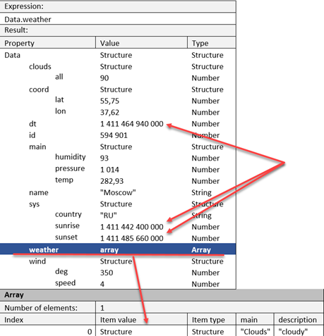
Fig. 484. Uploading result
If not consider conversion requirement, everything is expected. However, the date and time were not converted automatically. We can try to specify that the dt field (for example) is a field with date and time:
Read = New JSONReader;
Read.OpenFile("c:/temp/weather.json");
Data = ReadJSON(Read, False, "dt", JSONDateFormat.JavaScript);
Read.Close();This will result in the following error message:
Error when calling
context method (ReadJSON)
Data = ReadJSON(Read, False, "dt", JSONDateFormat.JavaScript);
reason:
Data presentation has
wrong formatThe reason for this error is that 1C:Enterprise does not get the date and time format expressed as a prime number. The API for JSON operations offers a function that helps to convert the Date – ReadJSONDate() fields. To use this function, align deserialized string with the JavaScript format, for example. The example will result in the following program text:
Data.dt = ReadJSONDate("new Date("+Format(Data.dt, "NG=")+")", JSONDateFormat.JavaScript);As a result, the value of Data.dt property will be equal to 23.09.2014 13:35:40 (Date type). The rest of conversion is performed in similar way.
16.2.3.3.3. Reading with the restoration function
The option with post processing is not really suitable if a JSON document needs to be read in different places within an application. In this case, the situation might happen, where the conversion code will be located in several places throughout the application.
The good replacement of post-processing in this case is the restoration function. To apply restoration function, describe the function and modify the document reading for a little bit:
&AtServer
Function ReadingRestorationFunction(Property, Value, AdditionalParameters) Export
If Property = "dt" Or Property = "sunrise" Or Property = "sunset" Then
Return
ReadJSONDate("new Date("+Format(Value, "NG=")+")", JSONDateFormat.JavaScript);
EndIf;
If Property = "pressure" Then
Return
Value*0.75;
EndIf;
If Property = "temp" Then
Return
Value-273.15;
EndIf;
If Property = "speed" Then
Return
Value*1.61;
EndIf;
EndFunction
&AtServer
Procedure ReadAtServer()
Read = New JSONReader;
Read.OpenFile("c:/temp/weather.json");
Data = ReadJSON(Read, False, , , "ReadingRestorationFunction", ThisObject);
Read.Close();
EndProcedureThe example above has one aspect: the restoration function will be called for all properties identified in the JSON document. This is not always convenient and reduces the JSON document reading performance (because of calling restoration function). For example, when reading weather data we need to perform a special conversion only for the properties containing date and time. We are not going to convert other properties. To avoid analyzing an attribute name in the restoration function (as in the example above), you can explicitly pass a list of attributes with date and time to a JSON document reading function and write the restoration function considering that it will be called only for required properties. The result is the following code:
&AtServer
Procedure ReadAtServer()
Read = New JSONReader;
Read.OpenFile("c:/temp/weather.json");
Attributes = New Array;
Attributes.Add("dt");
Attributes.Add("sunrise");
Attributes.Add("sunset");
Data = ReadJSON(Read, False, , , "ReadingRestorationFunction", ThisObject, , Attributes);
Read.Close();
EndProcedure
&AtServer
Function ReadingRestorationFunction(Property, Value, AdditionalParameters) Export
Return ReadJSONDate("new Date("+Format(Value, "NG=")+")", JSONDateFormat.JavaScript);
EndFunctionNote that the restoration function must be declared with Export keyword. Also remember that the restoration function (in managed form module) can only be described in a "context" module part using the &AtClient and &AtServer compilation directives. When developing the restoration function, consider that document properties are read in an order that is different from the order in the file.
Let us take a look at the sequence where JSON document properties get into the restoration function. To do this, we will place each file property in the table in the order of reading:
| JSON document data | Restoration function call sequence |
|---|---|
| { "id":524901, | 1 |
| "name":"Moscow", | 2 |
| "dt":1411464940000, | 3 |
| "coord": | 6 (structure) |
| { "lon":37.62, | 4 |
| "lat":55.75 }, | 5 |
| "sys": | 10 (structure) |
| { "country":"RU", | 7 |
| "sunrise":1411442400000, | 8 |
| "sunset":1411485660000 }, | 9 |
| "weather": | 14 (array) |
| [ | 13 (structure) |
| { "main":"Clouds", | 11 |
| "description":"cloudy" } | 12 |
| ], | |
| "main": | 18 (structure) |
| { "temp":282.93, | 15 |
| "pressure":1014, | 16 |
| "humidity":93 }, | 17 |
| "wind": | 21 (structure) |
| { "speed":4, | 19 |
| "deg":350 }, | 20 |
| "clouds": | 23 (structure) |
| { "all":90 } | 22 |
| 24 (structure) |
In general, the following iteration rule can be formulated: the first property to be read is the one with no subordinate properties. For example, there are no properties subordinate to id property and it will be read first. However, the coord property has the subordinate lon and lat properties. So, these properties will be read first, and only then the coord property will be read. It will get a structure (or a mapping) from the subordinate document properties as a value.
16.2.4. Operating XDTO objects
16.2.4.1. General information
Operations with XDTO objects are usually focused on information exchange between systems written on 1C:Enterprise platform. However, the mechanism itself imposes no restrictions for its usage and sharing with other systems.
JSON serialization of XDTO object is performed right into the JSON document without generating the full structure of serialized objects in memory. Also consider that JSON serialization "emulates" XML serialization. That is why, the resulting JSON document looks similar to XML document.
A JSON document can include any 1C:Enterprise objects that can be serialized to XDTO (see Specific features of using objects, their properties and methods). When attempting to serialize values of the unsupported type, the exception will be called.
16.2.4.2. Writing
To write a XDTO object in JSON format, use (in the simplest case) the following objects:
-
Object to write supporting conversion to/from XDTO, for example, a catalog item.
-
XDTO object serializer: XDTOSerializer.
-
Object that enables low-level data writing in JSON format: JSONWriter.
-
Serialization settings object: JSONSerializerSettings.
The serialization itself is performed using the WriteJSON() method of the XDTOSerializer object. Let us review the example of the CatalogObject type data serialization. The Currencies catalog will be used as an example. In contains the following fields: Rate (Number type) and RateDate (Date type):
Data = Catalogs.Currencies.FindByCode("978").GetObject();
Write = New JSONWriter;
Write.OpenFile("c:/temp/simpleXDTOWrite.json");
XDTOSerializer.WriteJSON(Writing, Data);
Write.Close();As a result, this example will generate the following JSON document:
{
"#value": {
"Ref":
"5b65bd8e-ea70-11e4-af93-e03f49b16069", "DeletionMark": false, "Code": "978", "Description": "Euro", "Rate": 54.659, "RateDate": "2015-04-25T00:00:00"
}
}The Date-type values are serialized in ISO format (identified by XDTO mechanism). The serialization is not managed when the data is being written. The conversion functions are also not supported during serialization, as opposed to stream method (see Stream method) and object method (see Object method).
Also remember that an object type is not generated when writing an object. That is why, after JSON serialization of an XDTO object, you cannot perform deserialization without specifying the type of the object to be read. The previous example of Currencies catalog item serialization will be impossible to deserialize without specifying the explicit value type. To make it simpler, you can use XMLTypeAssignment parameter of WriteJSON() method of XDTOSerializer object. If you set XMLTypeAssignment.Explicit as this parameter value, you will be able to deserialize without explicit type specification and the generated file will look as follows:
{
"#type":
"jcfg:CatalogObject.Currencies", "#value": {
"Ref":
"5b65bd8e-ea70-11e4-af93-e03f49b16069", "DeletionMark": false, "Code": "978", "Description": "Euro", "Rate": 54.659, "RateDate": "2015-04-25T00:00:00"
}
}In this example, pay attention to #type item, which described the current item type. For namespace prefix descriptions, see Namespace prefixes in JSON serialization.
General principles of JSON serialization of XDTO objects are the same as with XML serialization:
-
The data structure corresponds to the XML document structure.
-
There are minor differences associated with the specifics of type storage and presentation of arrays in JSON:
-
Order and content of properties are defined in XDTO model and cannot be changed.
-
If the type of the written value is defined unambiguously from the type, defined in the XDTO model property, then only the value without type identification is written.
-
If the type of the written value is defined ambiguously from the type, defined in the XDTO model property (for example, complex type value), the value will be written as a complex JSON object with dedicated properties for type (#type property) and value (#value property). The next example includes writing equivalent options of String-type value presentation. The first record is used when defining a type ambiguously, and the second record is used when defining a type unambiguously:
-
The first record
{
"#type": "jxs:string", "#value": "String with example"
}
The second record
"String with example"JSON serialization of XDTO objects has some aspects (as opposed to XML serialization):
-
Value collections (for example, values of the Array, Structure, and other types) are always written as a JSON array.
-
The attribute value type is written in a dedicated JSON property named #type.
-
The type namespace in a dedicated JSON property named #ns:
- For namespaces integrated into the platform, the types are written without #ns property but with a prefix:
jxc:ChartOfCharacteristicTypesObject.DemoChartOfCharacteristicTypes
jxs:string
jxs:decimalFor prefix and namespace matches, see Namespace prefixes in JSON serialization.
- If there is a schema without prefix, the schema name is written unambiguously using #ns property:
{
"#ns":
"http://mycompany.com/data/enterprise/myscheme", "#type": "SpecialObject", "#value": …
}The Undefined and NULL values are serialized in a special way:
- Undefined:
{
"#type": "jv8:Null", "#value": ""
}- NULL:
{
"AttributeName": null
}You can use JSON to serialize XDTO objects that do not correspond to any schema. In this case the explicit description of attribute types is used. The properties of the same name will not be connected into the array, but they will be included into the JSON document by element in accordance with the XDTO object.
Example:
{
"#type":
"jxs:anyType", "#value":
{
"Filters":
{
"Filter":
{
"Name":
"Recorder", "Value":
{
"#type":
"jxs:anySimpleType", "#value":
"acc2d259-c8f3-11e2-b5da-5404a6a68c42"
}
}
}, "Record":
{
"Recorder":
{
"#type":
"jxs:anySimpleType", "#value":
"acc2d259-c8f3-11e2-b5da-5404a6a68c42"
}, "Period":
{
"#type":
"jxs:anySimpleType", "#value":
"2012-09-08T00:00:00"
}, "Active":
{
"#type":
"jxs:anySimpleType", "#value":
"true"
}, }, "Record":
{
"Recorder":
{
"#type":
"jxs:anySimpleType", "#value":
"acc2d259-c8f3-11e2-b5da-5404a6a68c42"
}, "Period":
{
"#type":
"jxs:anySimpleType", "#value":
"2012-09-08T00:00:00"
}, "Active":
{
"#type":
"jxs:anySimpleType", "#value":
"true"
}, }, }
}16.2.4.3. Reading
In general, reading XDTO object from JSON document is similar to writing. The reading is performed using the mechanism for reading XDTO objects from XML file, so there are the following restrictions:
-
Only the objects with XDTO serialization can be read.
-
Properties in JSON document must follow the order of XDTO object.
-
When a readable object does not comply with the schema, an exception is thrown.
-
You can read arbitrary JSON document into XDTO object (XDTODataObject) using XDTO factory (XDTOFactory). Such reading is possible if:
-
The XDTO factory used for reading "knows" about types in JSON document, from which the data is read.
-
All JSON items are specified without explicitly specifying types and elements that are JSON document specific and generated during XDTO objects serialization.
-
If a JSON document has types that are unknown to the XDTO factory used to read it, the JSON document cannot be read.
Let us take a look at the example of reading a JSON document retrieved when operating the Currencies catalog from the previous section (see Writing).
Read = New JSONReader;
Read.OpenFile("c:/temp/simpleXDTOWrite.json");
Data = XDTOSerializer.ReadJSON(Reading);
Read.Close();As a result, the Data variable will include an object of the CatalogObject.Currencies type for the currency with code 978. However, such behavior will only be seen if the value of XMLTypeAssignment parameter was set to Explicit when performing JSON serialization. Otherwise, in an attempt to read the data (as stated above) the exception will be called. When reading an object with implicit specification of object type, the read type can be passed as a ReadJSON() method parameter. In this case, the example will look as follows:
Read = New JSONReader;
Read.OpenFile("c:/temp/simpleXDTOWrite.json");
Data = XDTOSerializer.ReadJSON(Read, Type("CatalogObject.Currencies"));
Read.Close();When exchanging data between applications using XDTO objects you might have a need to preprocess some data from exchange package. For example, change any value of some type to the fixed value of the same type. To simplify such preprocessing, there is a restoration function. The restoration function name is passed into the reading function from JSON document for serializer of XDTO factory. When reading the object, the restoration function will be called when serializing value of the following types:
-
Boolean
-
Number
-
String
-
Date
-
UUID
-
BinaryData
-
ValueStorage
-
Enumeration values
-
System enumeration values
-
Links to database objects.
The restoration function is not called for Undefined values.
When developing the restoration function, remember that in this function you can replace a value read from JSON document but you cannot change the readable object type. The restoration function will also not be called for system properties, which are created and used by 1C:Enterprise, for example, #type, #ns, and so on.
16.2.5. Stream method
16.2.5.1. General information
Stream method for document operation is designed to partially upload the document in the memory and process it sequentially, item by item. For example, if you need to read an object from a JSON document, the stream method can significantly simplify the process, especially if the required item is located at the beginning of the processed list.
16.2.5.2. Writing
To write the JSON document in stream, you need the data written and JSONWriter object. Keep in mind that the generation of the correct JSON document structure depends on the application developer, who generates the document. To simplify such control, the JSONWriter object has the ValidateStructure property.
Let us take a look at a simple example of document writing:
JSONParameters = New JSONWriterSettings(JSONLineBreak.Auto, " ", True);
Write = New JSONWriter;
Write.ValidateStructure = True;
Write.OpenFile("c:/temp/streamWrite.json", , , JSONParameters);
Write.WriteStartObject();
Write.WritePropertyName("RecordLength");
Write.WriteValue(20);
Write.WritePropertyName("Product");
Write.WriteStartObject();
Write.WritePropertyName("Code");
Write.WriteValue("0020");
Write.WritePropertyName("Name");
Write.WriteValue("Product");
Write.WriteEndObject();
Write.WritePropertyName("NumbersArray");
Write.WriteStartArray();
Write.WriteValue(3.141592654, True);
Write.WriteValue(2.718281828, False);
Write.WriteEndArray();
Write.WriteEndObject();
Write.Close();As a result of this code execution the following document will be generated:
{
"RecordLength": 20, "Product": {
"Code:" "0020", "Description:" "Product"
}, "NumbersArray": [
3.141592654E0, 2.718281828
]
}Such document format is convenient for visual viewing but take up more space. You can change the value of the first parameter of the JSONWriterSettings wizard to JSONLineBreak.No and the resulting document will look as follows (the difference is about 20%):
{"RecordLength":20,"Product":{"Code":"0020","Name":"Product"},"NumbersArray":[3.141592654E0,2.718281828]}If you need to retrieve the JSON document without file generation, use SetString() method of the JSONWriter object. After calling this method, to retrieve the string with the generated JSON document, you only need to complete the document writing with Close() method of the JSONWriter object:
JSONParameters = New JSONWriterSettings(JSONLineBreak.No, " ", True);
Write = New JSONWriter;
Write.SetString(JSONParameters);
…
Document = Write.Close();Now this document (from Document variable) can be passed to, for example, the HTTP request body.
16.2.5.3. Reading
Stream reading of a JSON document is similar to its writing: the application developer reads the next item in the loop, defines what has been read, and processes the data to be read.
The primitive case of stream reading may look as follows:
Read = New JSONReader;
Read.OpenFile("c:/temp/streamWrite.json");
While Read.Read() Do
Message("Current
item type " + Read.CurrentValueType);
If Read.CurrentValueType = JSONValueType.PropertyName Then
Message("Name
= " + Read.CurrentValue);
EndIf;
If Read.CurrentValueType = JSONValueType.Boolean Or
Read.CurrentValueType
= JSONValueType.String Or
Read.CurrentValueType
= JSONValueType.Number Or
Read.CurrentValueType
= JSONValueType.Comment Then
Message("Value
= " + Read.CurrentValue);
EndIf;
EndDo;
Read.Close();Upon reading the document generated when we looked at stream writing of JSON documents (see Writing), the following result will be generated:
Current item type Object start
Current item type Property name
Name = RecordLength
Current item type Number
Value = 20
Current item type Property name
Name = Product
Current item type Object start
Current item type Property name
Name = Code
Current item type String
Value = 0020
Current item type Property name
Name = Name
Current item type String
Value = Product
Current item type Object end
Current item type Property name
Name = NumbersArray
Current item type Array start
Current item type Number
Value = 3,141592654
Current item type Number
Value = 2,718281828
Current item type Array end
Current item type Object end16.2.6. Combining methods
To simplify operations with JSON, you can combine methods when generating one document. For example, you need to generate a document that includes some structure set and an array. In this case, you can generate the whole document with the stream method, and write generated structures and an array with the object method. Make sure that the document structure is correct before writing with object method.
Let us take a look at the example of method combination:
-
This system has to return list of orders as a response to external system request.
-
The list must contain generation date and a set of orders (that correspond to some criteria).
-
Each order is described by the following parameters:
-
Order number
-
Order generation date
-
Order counterparty
-
Unique order ID, which can be used to retrieve all order information.
-
A code fragment in 1C:Enterprise language that generates a JSON document will look as follows:
SerializationSettings = New JSONSerializerSettings;
SerializationSettings.DateWritingVariant = JSONDateWritingVariant.UniversalDate;
SerializationSettings.DateSerializationFormat = JSONDateFormat.ISO;
SerializationSettings.SerializeArraysAsObjects = True;
JSONParameters = New JSONWriterSettings(JSONLineBreak.Auto, " ", True);
Write = New JSONWriter;
Write.ValidateStructure = True;
Write.OpenFile("c:/temp/combinedWrite.json", , , JSONParameters);
Write.WriteStartObject();
Write.WritePropertyName("GenerationDate");
Write.WriteValue(WriteJSONDate(WhenGenerated, JSONDateFormat.ISO, JSONDateWritingVariant.UniversalDate));
Write.WritePropertyName("Orders");
Orders = New Array;
For each Order From OrderList Do
OrderDescription
= New Structure("Ref, Number, Date, Counterparty");
OrderDescription.Ref
= String(Order.Ref);
OrderDescription.Number
= Order.Number;
OrderDescription.Date
= Order.Date;
OrderDescription.Counterparty
= String(Order.Counterparty);
Orders.Add(OrderDescription);
EndDo;
WriteJSON(Write, Orders, SerializationSettings);
Write.WriteEndObject();
Write.Close();When executing such code, the following conditions must be met:
-
The WhenGenerated variable contains a value of the Date type. It contains a date and time when the JSON document was generated.
-
The OrderList variable is an array of links to order documents.
Executing this code leads to generation of the next JSON document:
{
"GenerationDate":
"2014-10-06T12:57:35Z", "Orders":
{
"0":
{
"Reference":
"f4d1495a-02b5-4d56-92c6-840c11dfb592", "Number":
234, "Date":
"2014-09-30T20:00:00Z", "Counterparty":
"J.A. Smith"
}, "1":
{
"Reference":
"ee821799-2d57-475e-a330-f414e53b8bda", "Number":
436, "Date":
"2014-09-24T20:00:00Z", "Counterparty":
"B.E. Collins"
}, "2":
{
"Reference":
"e058a5a8-3c0d-453b-8b1c-963a35fe2b7a", "Number":
118, "Date":
"2014-08-31T20:00:00Z", "Counterparty":
"J.A. Smith"
}
}
}By changing parameter values of SerializationSettings and JSONParameters objects and by manipulating parameters of WriteJSONDate() method you can change the resulting JSON document for maximum compliance with the "expectations" of the accepting system.
16.3. Binary data operations
16.3.1. General information
When implementing application, you might need to analyze various binary data. For example, you need to identify the file type by signature or manipulate the picture. To operate the binary data, 1C:Enterprise offers dedicated program interfaces. The binary data operation abilities are described below.
During the system operation, binary data is stored using the object with the same name: BinaryData. This object can be used to read data of any file irregardless of this file type. However, the data modification is not supported for this object. The only exception is an ability to split binary data in multiple parts of the specified size (SplitBinaryData() method) or vice versa (ConcatBinaryData() method).
All further binary data operations are based on the concept of stream. Stream is a logical summarization of an arbitrary (in general) data source (the Stream object). 1C:Enterprise does not allow creating an independent Stream object that is not related to a source. However, there are arbitrary objects that can be created. This is a stream related to a file on the hard drive (the FileStream object) or a stream created in memory (the MemoryStream object). Streams offer data reading and writing abilities. To verify the ability to perform operations, the stream (and derived objects) has special methods that allow you to verify that operations are available for this stream (CanWrite(), CanRead(), CanSeek() methods).
If you need to operate the stream on a higher level, in particular, read/write such data as number (with various bitness) or string there are DataReader/DataWriter objects. These objects enable more structured approach to binary data in the stream. For example, if you know the format of the file you can read this file quite easy by retrieving the required data from headers (which, as a rule, are presented by number and string types) passing the redundant data blocks and downloading the required ones.
The general scheme of binary data operations can be represented as follows:
-
A stream is retrieved.
-
The DataReader or DataWriter object is created.
-
The object created on Step 2 is used to perform the required actions.
-
The object created on Step 2 is closed.
-
If no more operations are required, the stream retrieved on Step 1 is closed.
-
If you need to continue operations with the stream, you can set new position in the stream (if this operation is supported) and continue from Step 2.
Note that you can combine steps 1 and 2. In other words, 1C:Enterprise provides the ability to create DataReader/DataWriter objects directly from, for example, BinaryData object.
To perform various operations with binary data, 1C:Enterprise provides an ability to retrieve a portion of the stream as a dedicated fragment with arbitrary (by byte) access (BinaryDataBuffer object). The buffer size is set upon creating and cannot be changed later. When using the binary data buffer, you can operate numbers with different bitness as a whole. You can also set the byte order using words: little endian or big endian. You can also split one buffer combine several binary data buffers into one resulting buffer.
Note that binary data buffer significantly simplifies implementation when the binary data operation is performed on the client application side in asynchronous mode. In this case the data will be read by asynchronous operation and the buffer data will be operated using the synchronous operation.
The binary data can be operated on the client application side (including the web client) and on the 1C:Enterprise server side as well as in synchronous and asynchronous operation mode. Examples below will demonstrate synchronous operation scheme.
16.3.2. Reading binary data
As an example of binary data reading we will review the task of defining the specific size of the file chosen in the system for further use. The .wav file with audio data will be used as a verified file. To store WAV files, use Resource Interchange File Format (RIFF). Its description is available at: https://msdn.microsoft.com/en-us/library/windows/desktop/ee415713.aspx. The following data on the format will be used for reading example:
-
The first 4 bytes of the file contain the format ID: RIFF.
-
The next 4 bytes contain the size of audio data with the little-endian byte order.
-
The next 4 bytes contain the text type of the data to be used: WAVE.
To perform these actions, the following code in 1C:Enterprise language will be required:
Read = New DataReader(FileName, , ByteOrder.LittleEndian);
FileFormat = Read.ReadChars(4);
DataSize = Read.ReadInt32();
FileType = Read.ReadChars(4);
If FileFormat <>
"RIFF" Then
Message("This is not RIFF file");
Return;
EndIf;
If FileType = "WAVE" Then
Message("This is a WAV file with data, its size is " + DataSize + " bytes");
Else
Message("This is not WAV file");
Return;
EndIf;Let us consider this example in detail.
At first, the file is opened with the name from FileName variable. The file is opened for reading (FileOpenMode.Open). The file will only be used for reading (FileAccess.Read) and for this the 16 bytes buffer will be used.
Then the stream for data reading is created, which will have the "younger-older" order for data of Number-type. Then 4 ASCII characters, 32-bit integer and 4 more ASCII characters are read from the resulting stream. The resulting data is analyzed, and the analysis results are used to decide, whether the chosen file is a .wav file or not.
16.3.3. Writing binary data
In the simplest case, the data are written to the file in the following way:
Record = New DataWriter(FileName);
For Index=0 To 255 Do
Write.WriteByte(Index);
EndDo;
Write.Close();This example writes the sequence of bytes from 0 to 255 (0xFF in hexadecimal notation) to the file. This is the simplest way to write.
You can also use the way that is similar to reading, reviewed in the previous example, when the file stream is retrieved and the data are written in this file stream.
16.3.4. Operations with the binary data buffer
As mentioned above, the binary data buffer is a convenient way to manipulate binary data fragments. Both reading and writing are supported.
As an example, we will review how to parse a RIFF file header from data reading example (see Reading binary data). To build the example, the same information o the file format will be used. So, the buffer with the size of file header will need to be read. The header consists of 4-byte fields. A total of 12 bytes needs to be read.
Buffer = New BinaryDataBuffer(12);
File = FileStreams.Open(TempFilesDir() + "Windows Logon.wav", FileOpenMode.Open, FileAccess.Read);
File.Read(Buffer, 0, 12);
Size = Buffer.ReadInt32(4);
StringStream = New MemoryStream(Buffer);
StringStream.GoTo(0, PositionInStream.Beginning);
ReadLine = New DataReader(StringStream);
FileFormat = ReadLine.ReadChars(4, "windows 1251");
ReadLine.Close();
StringStream.GoTo(8, PositionInStream.Beginning);
ReadLine = New DataReader(StringStream);
FileType = ReadLine.ReadChars(4, "windows 1251");
ReadLine.Close();The process of retrieving data to the binary data buffer has nothing special to it. Further operations require a comment. Reading number of any supported bitness is supported from any buffer position. In this example, Buffer.ReadInt32(4); means reading 32-bit integer starting from 4 byte of a buffer. So, if you need to read several numbers located in different parts of the buffer, you can do it without direct positioning in this buffer.
Reading the string, however, is not supported by the binary data buffer. That is why, you must use an object that allows reading: DataReader. The DataReader object cannot be created based on the binary data buffer. However, the binary data buffer can be used as a basis to create a stream that is a universal intermediary between physical storage location (file, binary data buffer) and high-level object, enabling operations with these data.
When the DataReader object is created based on some stream, it starts reading data from the positions currently set in the stream. In the example, the position is set in the stream first, and then the DataReader object is created and the required characters are read.
16.3.5. Values in binary and hexadecimal notation and logical operations
When operating with various binary formats, the so-called "magical numbers", that is constants or bit masks, are used quite frequently. Such magical number can be converted into decimal numbers, but such conversion increases risk of errors and is less obvious. To simplify operation with such magical number, there are global context functions: NumberFromHexString() and NumberFromBinaryString().
Example:
OlderBitMask = NumberFromBinaryString("0b10000000");
ParameterSet = NumberFromHexString("0x79E");The system also enables logical operations with binary data buffer. The following operations are supported:
-
Logical "And" (the WriteBitwiseAnd() method)
-
Logical "Or" (the WriteBitwiseOr() method)
-
Logical "exclusive Or" (the WriteBitwiseExclusiveOr() method)
-
Logical "and not" (a reverse operation to logical "And", the WriteBitwiseAndNot() method)
-
Inversion (the Invert() method)
Using these methods, you can perform various logical operations with data, including verification of specific bits setting. These methods operate with binary data buffers. So, the operation bitness is limited by the buffer size. For the example of how to use these methods, see the next section (see Specifications).
However, logical operations are increasingly frequently required to operate numbers with limited bitness. The platform provides a set of methods that simplifies manipulation of specific bits in numbers with limited bitness:
-
Functions for bits and masks: CheckBit(), CheckByBitMask(), and SetBit().
-
Bitwise logical operations: BitwiseAnd(), BitwiseOr(), BitwiseNot(), BitwiseAndNot(), and BitwiseXor().
-
Shifting operations: BitwiseShiftRight() and BitwiseShiftLeft().
When operating the above-mentioned functions, remember:
-
All operands are considered 32-bit unsigned integers. An attempt to other value as a parameter is considered invalid value of the parameter with exception generation.
-
The bit number is an integer from 0 (the youngest bit) to 31 (the oldest bit).
-
When shifting, the free digits are filled with 0.
16.3.6. Specifications
String operations
When using the binary data, remember about aspects of String-type data operation. The aspect is that the length of the string returned by the StrLen() global context function is calculated in characters. The sizes of data read/written in string writing/reading methods in binary data operation objects (ReadChars(), ReadLine(), WriteChars(), WriteLine()) should be specified in characters too. There is no single option for string length conversion to the similar parameter in bytes. Depending on the string content and coding, the ratio will be different. For example, in UTF-8 coding one character can take from one to six bytes. So, when operating some data structures with variable length strings, you need to know clearly what are the length units specified.
In case you need to convert strings to byte set and vice versa, use GetBinaryDataFromString()/GetBinaryDataBufferFromString() methods and opposite methods: GetStringFromBinaryData()/GetStringFromBinaryDataBuffer().
These methods allow specifying the string coding and the need to use BOM (Byte Order Mark for Unicode). When converting strings to byte set, the size of resulting string can be retrieved via the standard interface for retrieving resulting object size (BinaryData.Size() or BinaryDataBuffer.Size).
Thus, the binary data can be retrieved from the string in the following way:
Data = GetBinaryDataFromString("String sample for conversion", "UTF
8", False);
StringSizeInBytes = Data.Size();The opposite operation is performed in the following way:
-
The binary data buffer of the required size is retrieved from the reading stream.
-
The resulting binary data buffer is converted into the string.
In 1C:Enterprise language, this operation will look as follows:
// ReadingStream is an
existing reading stream
Buffer = ReadingStream.ReadIntoBinaryDataBuffer(StringLengthInBytes);
StringRead = GetStringFromBinaryDataBuffer(Buffer);Shared use of different objects
It is not recommended to use the DataReader/DataWriter objects and stream objects simultaneously. If the position in a stream that the DataReader/DataWriter objects operate with is changed between two sequential DataReader reading operations or two sequential DataWriter writing operations, an exception is thrown. The next example shows the correct change of position in the stream when writing data to the stream:
Stream = New MemoryStream();
DataWriter = New DataWriter(Stream);
DataWriter.WriteLine("Hello
world!");
DataWriter.Close();
Stream.GoTo(0, PositionInStream.Beginning);
DataWriter = New DataWriter(Stream);
DataWriter.WriteLine("Bye!");
DataWriter.Close();The next example results in exception:
Stream = New MemoryStream();
DataWriter = New DataWriter(Stream);
DataWriter.WriteLine("Hello
world!");
Stream.GoTo(0, PositionInStream.Beginning);
// Exception will be
generated in the next string
DataWriter.WriteLine("Bye!");At the same time, there might be situations when the system behavior is incorrect but no errors are generated:
Stream = GetStream();
DataReader = New DataReader(Stream);
TestString = DataReader.Read();
OriginalPosition = Stream.CurrentPosition();
DataWriter = New DataWriter(Stream);
DataWriter.WriteLine("Unexpected
stream");
DataWriter.Close();
Stream.GoTo(OriginalPosition, PositionInStream.Beginning);
// In general, you
cannot define which value will be placed to the TestString2 variable
TestString2 = DataReader.ReadLine();The reason for the behavior described in this section is that DataReader/DataWriter objects use their own buffers when operating the stream. As a result, the actual position of the stream differs from the logical position, which is generated as a result of performed operations.
Also, simultaneous use of DataReader and DataWriter objects, which use one stream, is not supported.
Bitwise operations without buffer usage
Verifying and setting digits in a data set, which, for example stores a set of Boolean flags, is used quite frequently. If dataset is presented by the unsigned integers with no more than 32 digits in "length", then to verify the section you can use dedicated functions. Below, you can see an example of how to use the functions. If the operand bitness is more than 32, it is recommended to use the next example in this section.
To verify the state of a number bit, you can use the following functions: CheckBit() and CheckByBitMask(). The difference is that using the second function, you can verify several checkboxes in one value.
Using this function (LogicalAnd()) can be illustrated with the following example:
READ = NumberFromBinaryString("0b00000001"); // 0 bit
CREATE = NumberFromBinaryString("0b00000010"); // 1 st bit
CHANGE = NumberFromBinaryString("0b00000100"); // 2 nd bit
DELETE = NumberFromBinaryString("0b00001000"); // 3 rd bit
AccessFlags = NumberFromBinaryString("0b00001110");
// verify a certain bit
CanRead = CheckBit(AccessFlags, 0);
// verify by mask
(several flags)
CanWrite = CheckByBitMask(AccessFlags, CREATE+CHANGE);In this example, we review a byte that contains flags defining operations with the supposed file. Each flag is defined by its mask (READ, CREATE, CHANGE, DELETE variables). In the example above, the AccessFlags value describes the following set of flags:
-
Reading is unavailable. 0 bit is cleared.
-
Creating is possible. 1st bit is cleared.
-
Change is possible. 2nd bit is cleared.
-
Deleting is possible. 3rd bit is cleared.
Verification of the specific bit is performed during verification of ability to read by the presented mask. If you need to verify another AccessFlags digit, change the value of the second parameter when calling the CheckBit() function. However, if you need to verify several digits at once, use the CheckByBitMask() method instead of the CheckBit() function. The second parameter of this function sends a verification mask, which includes 1 values in the verifiable digits. If all the required digits in the mask also include 1, the result of this function will be True. In the example, the following digits are verified at the same time: CREATE and CHANGE. Combining these two values results in the required mask, verified by CheckByBitMask() method.
Simplifying bitwise operations
Verifying and setting digits in a data set, which, for example stores a set of Boolean flags, is used quite frequently. If values do not exceed 32 digits in "length", such verifications are described in the previous example of this section. If "longer" numbers are used (bitness is more than 32), the required functions can be implemented using 1C:Enterprise language. Note that since 1C:Enterprise type system does not support specialized unsigned types of a limited bitness, all further methods are based on the suggestion that unsigned integers are passed. In spite of what is said above (about the bitness of more than 32 digits) the examples operate 8-bit numbers. This is done to simplify the example. This example also does not consider the byte order in the buffer. The youngest value is always located in the youngest byte of the generated binary data buffer. This suggestion is true for both axillary method below.
To implement this operation, two auxiliary functions will be required. The first one will convert the passed number into the binary data buffer of the required size, and the second one will convert binary data buffer to the Number type value.
Function SplitNumberByBytes(Val Number, BytesNumber = 0, Filler = 0)
// split the passed number into bytes
Number = Int(Number);
ArrayByBytes = New Array;
While Number > 0 Do
ArrayByBytes.Add(Number % 256);
Number = Int(Number / 256);
EndDo;
// if the specific number bitness is required, do it here
If BytesNumber <> 0 Then
If BytesNumber < ArrayByBytes.Number() Then
// cut the result off to fit the set size
While ArrayByBytes.Number() > BytesNumber Do
ArrayByBytes.Delete(BytesNumber);
EndDo;
Else
// add high-order bytes from the filler
Difference = BytesNumber - ArrayByBytes.Number();
While Difference <> 0 Do
ArrayByBytes.Add(Filler);
Difference = Difference - 1;
EndDo;
EndIf;
EndIf;
BinaryDataBuffer = New BinaryDataBuffer(ArrayByBytes.Number());
For Counter = 0 To ArrayByBytes.Number() 1 Do
BinaryDataBuffer[Counter] = ArrayByBytes[Counter];
EndDo;
Return BinaryDataBuffer;
EndFunction
Function CollectNumberFromBytes(BinaryDataBuffer)
Result = 0;
Position = 0;
For each Byte In BinaryDataBuffer Do
Result = Result + ?(Position = 0, BinaryDataBuffer[Position], BinaryDataBuffer[Position] * Pow(256, Position));
Position = Position + 1;
EndDo;
Return Result;
EndFunctionThen the operation of the logical "And" for two numbers will look as follows:
Function LogicalAnd(Val
Operand1, Val Operand2, Val OperandLength = 0)
Buffer1 = SplitNumberByBytes(Operand1);
OperandLength = ?(OperandLength = 0, Buffer1.Size, OperandLength);
Buffer2 = SplitNumberByBytes(Operand2, OperandLength);
Buffer1.WriteBitwiseAnd(0, Buffer2, OperandLength);
Result = CollectNumberFromBytes(Buffer1);
Return Result;
EndFunctionIn this case, the size of the second operand in the operation is supposed to be equal to the size of the first operand.
Using this function (LogicalAnd()) can be illustrated with the following example:
READ = NumberFromBinaryString("0b00000001");
CREATE = NumberFromBinaryString("0b00000010");
CHANGE = NumberFromBinaryString("0b00000100");
DELETE = NumberFromBinaryString("0b00001000");
AccessFlags = NumberFromBinaryString("0b00001110");
CanRead = LogicalAnd(AccessFlags, READ);
CanWrite = LogicalAnd(AccessFlags, CREATE+CHANGE);
FullAccess = LogicalAnd(AccessFlags, CREATE+CHANGE+READ+DELETE);In this example, we review a byte that contains flags defining operations with the supposed file. Each flag is defined by its mask (READ, CREATE, CHANGE, DELETE variables). The flag is easily verified: if the result of the LogicalAnd() function is not equal to the sum of the flags to be verified, not all the flags to be verified are set. If the function result equals the sum of verifiable flags, it means that all verifiable flags are set. In the simplified case, verification of one flag returns 0 value if the flag is not set, and it returns a flag value if the flag is set.
In the example for AccessFlags flags above:
-
Reading is unavailable. The CanRead variable value is 0.
-
Writing is not possible. The CanWrite variable value is 6, which is the sum of the CREATE and CHANGE flags.
-
Full access is not possible. The FullAccess variable value is 15, which is the sum of all the described flags except for the unavailable READ flag.
You can perform the other functions for bitwise data operation similar to the LogicalAnd() method.
16.4. PDF format
16.4.1. General information
1C:Enterprise enables you to save spreadsheet documents and representable document batches in PDF format. Moreover, both spreadsheet documents and representable document batches can be saved in PDF format (it is described by ISO 32000-1). Besides, you can save spreadsheet documents in any of long-term storage formats: PDF/A-1 (ISO 19005-1), PDF/A-2 (ISO 19005-2), and PDF/A-3 (ISO 19005-3).
When you save a document in PDF/A format, note the following:
-
A document is saved in PDF 1.4 format (for PDF/A-1 only).
-
Duplex printing is not supported.
-
The source of paper in accordance with PDF-document size cannot be chosen during printing.
-
No transparency is supported (for PDF/A-1 only).
-
The version history of the platform used for the spreadsheet writing and the document creation dates are saved when a document is written.
To save a document in PDF format, specify the following:
-
SpreadsheetFileType of the SpreadsheetDocument.Write() method.
-
FileType of the RepresentableDocumentBatch.Write() method.
In addition to saving in PDF format, the platform as well enables you to manage attachments which may be available in a PDF document. You might need it to create a document containing both human and machine-readable sections. As an example, let us consider an invoice that is saved in PDF and can be viewed and printed (to the extent of its human readable section). At the same time, a PDF document has an attached XML file that describes the invoice content and can be read by any software.
PDF application interface enables you to manage digital signatures available in a document. Moreover, you can verify and apply restrictions to a document, add a further signature, validate existing signatures and place a digital signature representation on the document page. Note that a PDF document signed with a digital signature cannot be edited without making the signature invalid. This rule applies both to the document and all attachments.
The existing PDF document handling model fails to support tools enabling users to programmatically modify a human readable section.
16.4.2. Attachments
16.4.2.1. Writing attachments
Use PDFWriter to write attachments to PDF documents. The said object is available both on the client and on the server side in either asynchronous or synchronous mode. In the documentation, examples where operations are performed in the synchronous mode will be given only (to reduce their scope). You can use attachments in PDF documents saved in 1.5 or any later version.
Generally, attachments are added as follows:
-
Create PDFWriter on the basis of a file or thread. If this object is created without a reference to its source, open a PDF document using the PDFWriter.Open() method.
-
An attachment collection is now generated for a PDF document. To get an attachment collection, use PDFAttachmentCollection. To add attachments, use PDFAttachmentCollection.Add().
-
An attachment collection is added to an opened document using PDFWriter.WriteAttachments().
-
To close a PDF document, use PDFWriter.Close().
When you write it, attachments with their names being similar to those available in the collection are replaced. As such, "name" means PDFAttachment.FileName property value (PDFAttachmentCollection collection element). If any object is deleted from an attachment collection, it means that it is as well deleted at the file level. 1C:Enterprise cannot compare attachment lists on element-by-element basis (that is, a list of existing attachments and a list of attachments to write).
If you need to delete an attachment from a file, use PDFWriter.WriteAttachmentsDeletion(). In this case, objects are also mapped by their names: each array element represents a value of the PDFAttachment.FileName property. Note that physically no attachment is deleted. They are just marked as deleted. PDF viewer allows you to return to any attachment so deleted.
16.4.2.2. Reading attachments
Use PDFReader to read attachments to PDF documents. The said object is available both on the client and on the server side in either asynchronous or synchronous mode. In the documentation, examples where operations are performed in the synchronous mode will be given only (to reduce their scope).
Generally, attachments are read as follows:
-
Create the PDFReader object based on a file or a thread. If this object is created without a reference to its source, open a PDF document using the PDFReader.Open() method.
-
To receive an attachment collection from a PDF document, use PDFReader.GetAttachments().
-
To close a PDF document, use PDFReader.Close().
An attachment collection can exist independently of the PDFReader object. So, if you need to delete an attachment from an existing PDF file, do the following:
-
Open an existing PDF document: create an object using the wizard or the PDFReader.Open() method.
-
Get an attachment using PDFReader.GetAttachments().
-
Close PDFReader using PDFReader.Close().
-
Use so retrieved to update a PDF document. For that purpose, use PDFWriter.
16.4.3. Digital signature
16.4.3.1. General information
For the terms used in the section, see Basic concepts. When necessary, these terms will be adjusted and updated. In this section, "a digital signature" denotes an electronic signature that consists of the following parts: a digital signature in cryptographic terms (data sequence generated as a result of cryptographic conversion of source data) and its graphic presentation.
There are two kinds of digital signatures (in an attachment to a PDF document): approving and certifying signatures. A single document can have several approving digital signatures. If a document is signed with an approving digital signature, you can disable its further editing. In each document there is only one certifying digital signature. However, document editing can be allowed, provided that modifications so made have no impact on its content (for instance, comments can be added).
An approving digital signature can be used as follows:
-
A document (for instance, a sales quotation) is created.
-
Its author signs the document with an approving signature and certifies its content and their authorship.
-
Then the a sales quotation is sent to the company's marketing director. They verify the document, sign it with their approving digital signature, and lock the document.
-
Now, the document is approved by all responsible persons (using digital signatures) and locked from editing.
A certifying digital signature can be used as follows:
-
There is a document which needs to be delivered for reviewed and approval through open communication channels.
-
An author creates a document and signs it with their certifying digital signature. This way, they allow reviewing and commenting the document.
-
Further, it is handled by a reviewer who makes his or her comments and redelivers the same to the sender. However, both parties know that the document remains unmodified (it is guaranteed by the said signature).
It should be noted that classification of digital signatures described in this section applies exclusively to and is defined by PDF format. Moreover, legal definition of a digital signature and its classification (see applicable regulations) generally is not in any way associated with the definitions used in this section.
16.4.3.2. Adding signatures
To add a digital signature, use objects to perform PDF document operations and cryptographic tools provided by the platform.
To sign a PDF document, do the following. Create an object that describes a digital signature: Signature = New PDFSignatureDescription();. Let us see how you can use the object properties.
The following properties are important for any signature:
-
Certificate. This property must always be filled with a link to a public key certificate, which is used to verify a generated digital signature.
-
SignatureType. Defines a digital signature to be used to sign a document. Depending on the signature type, you need to define one of the following properties.
-
DocumentLock. If the SignatureType property is set to Approving, set it to True to restrict any document modification after it is signed. For an approving digital signature, there is no point in setting the ModificationAccessPermissions property.
-
ModificationAccessPermissions. If the SignatureType property is set to Certifying, use this property to specify actions that the user can perform with a signed document. Anyway, no action so performed can modify the content of a duly signed document. For a certifying digital signature, there is no point in setting the DocumentLock property.
If graphic representation of a digital signature is used when you execute a document, its location in a document is defined by the following properties:
-
PageNumber. Defines a page in PDF document where graphic presentation of a digital signature is made available. Page numbering starts from 1.
-
Left and Top. Define a distance from the left and right page boundaries (accordingly), where graphic presentation of a digital signature is made available. The zero point is in the top left corner of a page. The said distance is set in mm.
-
Width and Height. Define the size of graphic presentation of a digital signature horizontally and vertically (accordingly).
As soon as an object which describes a digital signature is created and filled with data, you can add a digital signature to a PDF document.
To add a digital signature, do the following:
-
Create an object for access to cryptographic functionality.
-
Get a certificate to verify a digital signature as a separate object (CryptoCertificate).
-
Create and fill in PDFSignatureDescription.
-
Create an object allowing it to add a digital signature to a PDF document (PDFWriter).
-
Sign a PDF document using PDFWriter.WriteSignature().
An example of signing a document:
SpreadsheetDocumentAgreement.Write(DocumentName,SpreadsheetDocumentFileType.PDF);
CryptoManager = New CryptoManager("", "", 80);
CryptoManager.PrivateKeyAccessPassword = Password;
Certificate = GetPublicCertificate();
Stamp = GetTemplate("SignPDF");
SignPDF = New PDFSignatureDescription;
SignPDF.Name = "SignAgreement";
SignPDF.Certificate = Certificate;
SignPDF.SignatureType = PDFSignatureType.Approving;
SignPDF.DocumentLock = True;
PDFWriter = New PDFWriter(DocumentName);
PDFWriter.WriteSignature(CryptoManager, SignPDF, Stamp);See also:
- Cryptographic operations (see Cryptographic feature).
16.4.3.3. Signature verification
The following two options are available for a signed PDF document:
-
Get a list of all digital signatures used to sign a document for further review and analysis.
-
Verify all digital signatures or a single signature only selected by a user.
No digital signature that has already been used to sign a document can be modified.
To get a list of signatures used to sign a document, select PDFReader.GetSignatureDescriptions(). The function returns a signature description object array.
CryptoManager = New CryptoManager("", "", 80);
CryptoManager.PrivateKeyAccessPassword = Password;
PDFReader = New PDFReader(DocumentName);
Signatures = PDFReader.GetSignatureDescriptions(CryptoManager);However, the primary task of a digital signature is to make sure that a document has not been modified since you signed it. The following two methods are used for this purpose:
- Verify all digital signatures used to sign a document. For this purpose, you can use PDFReader.VerifySignatures().
An example of how to verify all signatures:
CryptoManager = New CryptoManager("", "", 80);
CryptoManager.PrivateKeyAccessPassword = Password;
PDFReader = New PDFReader(DocumentName);
Try
PDFReader.VerifySignatures(CryptoManager);
Except
Notify("Signatures
are not valid!");
EndTry;- Verify a single digital signature used to sign a document. For this purpose, you can use PDFReader.VerifySignature().
An example of how to verify a single signature:
CryptoManager = New CryptoManager("", "", 80);
CryptoManager.PrivateKeyAccessPassword = Password;
PDFReader = New PDFReader(DocumentName);
Signatures = PDFReader.GetSignatureDescriptions(CryptoManager);
For every CurrentSignature from Signatures Do
Try
PDFReader.VerifySignature(CurrentSignature.Name, CryptoManager);
Except
Notify("Signature"
+ CurrentSignature.Name +" is not valid!");
EndTry;
EndDo;16.4.3.4. Adding signature presentations
In addition to adding a signature, the platform allows you to add a signature presentation to a PDF document. You can use the Picture and SpreadsheetDocument objects as a signature presentation.
To add a signature presentation, use an object of the PDFRepresentationObjectDescription type. To specify a signature presentation, use the Object property of this type. This is the only required property. The other properties have the following purpose:
-
Name. Name of the presentation to be added.
-
PageNumber. Number of the page where the signature presentation will be located. Numbers start from 1. If this property is empty, the object will be located on the last page of the document.
-
Left, Top. Coordinates of the upper left corner of the object to be added on a document page. Coordinates are specified in millimeters relative to the top left corner of a page. If these values are not specified, the system will select them automatically.
-
Width, Height. Size of the object to be added on a page, in millimeters. If these values are not specified, the system will select them automatically.
To add the created representation object description to a PDF document, use the PDFWriter.WriteRepresentationObject() method. So, a code that adds a picture to a PDF document can look as follows:
Spreadsheet = GenerateSpreadsheetDocument();
Spreadsheet.Write(FileName, SpreadsheetDocumentFileType.PDF);
Description = New PDFRepresentationObjectDescription;
Description.Name = "EmployeeSignature";
Description.Object = PictureLib.Signature;
PDFWriter = New PDFWriter(FileName);
PDFWriter.WriteRepresentationObject(Description);16.4.4. PDF document
16.4.4.1. General information
The previous sections described methods for using a PDF document to perform atomic actions: write/read attachments and sign documents/verify signatures. In some cases, you might need to perform all these actions for the same document at once. Immediately after that, you might want to print this PDF document. To perform all these actions, use the PDFDocument object. This object is available both on a client application and 1C:Enterprise server. In a client application, you can perform only asynchronous operations. In this case, a method name ends with the Async suffix. On 1C:Enterprise server, you can perform only synchronous methods. Also consider that when working in the web client, you need to install 1C:Enterprise Extension (to use theReadAsync(), WriteAsync(), AddSignatureAsync() and AddRepresentationObjectAsync() methods).
The PDFDocument object allows you to perform the following actions:
-
Get a document type and a list of its attachments.
-
Add/delete an attachment, clear the list of attachments.
-
Use digital signature sets and the list of displayed objects.
-
Print a PDF document.
This section describes how to use the PDFDocument object in more detail.
16.4.4.2. Reading and writing a document
To read a PDF document, use the PDFDocument.Read() method. For example, in the following code:
Document = New PDFDocument;
Await Document.ReadAsync(FullDocumentPath);
Message("Document type - " + Document.FileType);
Message("Attachments - " + Document.Attachments.Count());The FileType property specifies a format in which the opened document is written: a standard format or any PDF/A format for long-term storage. The Attachments property grants access to the opened document attachments.
You can open a file both from the hard drive and a stream. In this case, only the first parameter value of the Read()/ReadAsync() methods is different.
You can protect PDF documents with a password. You can pass a password as the second parameter value of the Read()/ReadAsync() methods. To check whether a PDF document has a password, use the DocumentIsPasswordProtected()/DocumentIsPasswordProtectedAsync() global context methods. These methods return True if the document is password-protected. However, this method does not allow you to find out the password. You can check both a file and a document in a stream.
Once a PDF document is modified, you can write it to a file on the hard drive or a stream. To do it, use the Write()/WriteAsync() methods. When writing, you can set a password (the second method parameter). You can also use the third method parameter to specify the format for writing a PDF document: a standard format or any PDF/A format for long-term storage.
16.4.4.3. Attachment operations
To manage attachments of an opened PDF document, use the Attachments property. This property is a collection of attachments (the PDFAttachmentCollection value type). You can perform the following actions with attachments in use:
-
Add an attachment to the collection: Add().
-
Get an attachment from the collection: Get().
-
Delete an attachment: Delete().
-
Clear the collection: Clear().
-
Find an attachment by file name: Find().
-
Get collection parameters: Count().
Operations with this collection do not differ from similar object collections.
16.4.4.4. Document pages
The PDFDocument object contains the Pages collection, which contains information about each page included in the document (you cannot edit the content). The property is a collection of the PDFPagesCollection type. The PDFPage object is a collection element. Use this object to get the following document page parameters:
| Property | Description |
|---|---|
| Height | Page height in millimeters. |
| Number | Current page number of the document. Numbering starts with 1. |
| Orientation | Contains an angle (in degrees) by which the document page is rotated. |
| TopMargin | Contains the top margin of the page in millimeters. |
| LeftMargin | Contains the left margin of the page in millimeters. |
| BottomMargin | Contains the bottom margin of the page in millimeters. |
| RightMargin | Contains the right page margin in millimeters. |
| Width | Page width in millimeters. |
Cannot set page properties using the PDFPage object. They are read-only.
When placing signatures on PDF document pages (the AddSignature()/AddSignatureAsync() methods) or objects (the AddRepresentationObject()/AddRepresentationObjectAsync() methods), you can take into account the orientation of the document pages.
Let’s clarify the parameter that allows taking page orientation into account. The page height and width parameters, which are located in the same-named properties of the PDFPage object, do not take into account the Orientation property value. In other words, if a page is in A4 (portrait) format and rotated by 90 degrees, the PDFPage object properties will have the following values: Height = 297, Width = 210, and Orientation = 90. If an object is added to a page in a specific location, there are two ways to solve this issue: perform all the recalculations manually when placing the object on the page, or place the object based on a standard size (height and width), and let the platform perform all the recalculations if the ConsiderPageOrientation parameter is set to True. Thus, setting the ConsiderPageOrientation parameter allows a developer to always position the object exactly where needed without additional calculations.
16.4.4.5. Operations with signatures and displayed objects
Once a PDF document is read, the PDFDocument object allows you to use digital signatures and displayed objects. For the main approaches to operating with digital document signatures, see Digital signature. When you use an object of the PDFDocument type, you can perform all operations with signatures using the document itself. You do not need to open a PDF document for reading and writing separately.
To get a list of signatures in the used document, use a program code similar to the following one:
Document = New PDFDocument;
Await Document.ReadAsync(FullDocumentPath);
CryptoManager = New CryptoManager("", "", 80);
CryptoManager.PrivateKeyAccessPassword = PrivateKeyPassword;
Signatures = Await
Document.GetSignatureDescriptionsAsync(CryptoManager);After this code is executed, the Signatures variable will contain an array with signatures of the opened document (the PDFSignatureDescription type values).
To verify document signatures, use one of the following methods:
-
Verify every signature separately using the PDFDocument.VerifySignature() method or its asynchronous version.
-
Verify all signatures that are set for a document using the PDFDocument.VerifySignatures() method or its asynchronous version.
Signature verification is performed as follows:
Certificates = Undefined;
Certificates = Await
Document.VerifySignaturesAsync(CryptoManager);The Certificates variable will contain a list of certificates used to sign the document. If you cannot verify signatures, an exception will be thrown. To add a signature, use the PDFSignatureDescription object and the PDFDocument.AddSignature() method or its asynchronous version.
To add a displayed object to a PDF document, use the PDFDocument.AddRepresentationObject() method (or its asynchronous version) or the PDFRepresentationObjectDescription object. As an example, consider adding a signature to a document. The position and size of the picture to add depend on the document page format (paper size):
Document = New PDFDocument;
Document.Read(FullDocumentPath);
PageCount = Document.Pages.Count();
If PageCount > 0 Then
LastPageIndex
= PageCount - 1;
LastPage = Document.Pages.Get(LasrPageIndex);
FilterObject = New PDFRepresentationObjectDescription;
FilterObject
.Name = "Signature";
ObjectFilter.PageNumber
= LastPageIndex + 1;
ObjectFilter.Left
= LastPage.LeftMargin;
If LastPage.Width = 297 And LastPage.Height = 210
Or
LastPage.Width = 210 And LastPage.Height = 297 Then
// Page A4
// Use a big
picture
FilterObject.Object
= PictureLib.BigSignature;
ObjectFilter.Top
= LastPage.Height - LastPage.BottomMargin - 100;
ElsIf Last.Width = 210 And LastPage.Height = 148
Or
LastPage.Width = 148 And LastPage.Height = 210 Then
// Page A5
// Use a
medium picture
FilterObject.Object
= PictureLib.MediumSignature;
Or
LastPage.Width = 148 And LastPage.Height = 210 Then - LastPage.BottomMargin - 50;
Else
// For the
remaining pages, use a small picture
FilterObject.Object
= PictureLib.SmallSignature;
ObjectFilter.Top
= LastPage.Height - LastPage.BottomMargin - 25;
EndIf;
Document.AddRepresentationObject(FilterObject);
Document.Save(FullDocumentPath);
EndIf;Once changes are applied in a read PDF document, save the document to the hard drive. Otherwise, the applied changes will be lost.
16.4.4.6. Viewing and printing a document
Use the PDFDocument object to show a read document to the user and print it.
To display a PDF document in a separate form, use the Show() method. You cannot use this method for a client application form attribute of the PDFDocument type.
To print a document, use the Print() method. Before printing, you can open a dialog box with document print parameters. Also, you can receive the number of pages in the read document. To do it, use the PageCount() method.
16.4.5. Other features
In 1C:Enterprise, you can convert documents into black and white. After that, all colored fragments in the document will be shown in grayscale. The document will look like a colored document printed on a black and white printer. To do it, use the ConvertToGrayScale() method of the PDFWriter and PDFDocument objects.
16.5. Regular expressions
16.5.1. General information
You have a problem.
You decided to use regular
Expressions to solve it.
Now you have two problems.
Upon text processing, the ongoing task is to search for any occurrences of one text in another. For example, when analyzing a log, you need to find all the lines that start with the "ERROR" text. Such search is quite simple. Another search option is to find all words that begin with a capital letter and are 5 to 8 characters long. The first goal is quite simply achieved by iterating strings using the StrStartsWith() function or a similar string processing function. The second example, on the other hand, requires a more complex algorithm, which needs to be constantly refined as the condition becomes more complicated or upon search condition changes. To simplify complex search for information in the text, there is a special tool called regular expressions.
Regular expressions, regexp are a special language designed to search for information in the text. It is based on wildcard characters. The search is performed using a special pattern, which is called a template or a wildcard. A template consists of regular characters and wildcard characters that identify text to be found. In other words, the template defines search rules.
The regular expression language is not an easy one. At the same time, this language does not have a single standard. That is why there are numerous implementation options of regular expressions. These options are called dialects. We will not fully describe regular expressions of any dialect in this section. This section contains a brief description of the main ICU dialect features. ICU is based on the Perl language dialect but extended with Unicode character operations. We picked this dialect since it is used by 1C:Enterprise. The dialect used in 1C:Enterprise fully applies to texts containing Unicode characters without any additional settings.
All the examples given in this section are not solutions of any actual tasks. They only demonstrate how you can solve a particular problem using regular expressions. To study regular expressions in more detail, use special literature. You will not find comprehensive information on the topic in this section. If you are interested in regular expressions, you might find useful the following sources:
The more you use regular expressions, the better you understand them and where you can apply them.
To debug regular expressions, you can use various Internet resources or software. For example, the https://regex101.com/ website. However, this is just one of many available tools.
See also:
-
XPath expression language.
-
The LIKE statement of the query language.
16.5.2. Language description
A regular expression template consists of a string that contains both regular literals and wildcard characters. In addition, you can use the […] expression to combine literals and wildcard characters into character classes. Regular expressions also include operators and search flags. In this section, we will use the term expression, which can consist of one:
-
Character
-
Wildcard character
-
Character class
-
Another expression (subexpression) if it is enclosed in parentheses (...).
The used regular expression dialect does not support named groups in regular expressions.
Regular expression operators:
| Operator | Operator details |
|---|---|
| | | "OR" condition. One of items separated by the operator is matched. Each expression involved in the "OR" operator is called an alternative. |
| * | The preceding expression is matched 0 or more times. The result will contain the maximum number of characters. |
| + | The preceding expression is matched 1 or more times. The result will contain the maximum number of characters. |
| ? | The preceding expression is matched 0 or 1 times. 1 occurrence is preferred. |
| {min} | The preceding expression is matched exactly min times. |
| {min,} | The preceding expression is matched min or more times. The result will contain the maximum number of matches. |
| {min,max} | The preceding expression is matched from min to max times. The result will contain the maximum number of matches, but no more than max. |
| *? | The preceding expression is matched 0 or more times. The result will contain the minimum number of characters. Lazy operator. |
| +? | The preceding expression is matched 1 or more times. The result will contain the minimum number of characters. Lazy operator. |
| ?? | The preceding expression is matched 0 or 1 times. 0 occurrences are preferred. Lazy operator. |
| {min}? | The preceding expression is matched exactly min times. Lazy operator. |
| {min,}? | The preceding expression is matched at least min times, but no more than it is required for a full match with the expression. Lazy operator. |
| {min,max}? | The preceding expression is matched from min to max times. The result will contain the minimum number of matches, but not less than min. Lazy operator. |
| *+ | Indicates 0 or more occurrences. Possessive operator. |
| ++ | Indicates 1 or more occurrences. Possessive operator. |
| ?+ | Indicates 0 or 1 occurrences. Possessive operator. |
| {min}+ | The preceding expression is matched exactly min times. Possessive operator. |
| {min,}+ | The preceding expression is matched min or more times. The result will contain the maximum number of matches. Possessive operator. |
| {min,max}+ | The preceding expression is matched from min to max times. The result will contain the maximum number of matches, but no more than max. Possessive operator. |
| () | Describes the capturing group. |
| (?:...) | Non-capturing group. Groups expressions but does not capture the corresponding text. A backreference wildcard character (/num) cannot be applied to such groups. |
| (?>...) | Atomic group. An atomic group is a non-capturing group that additionally prevents backtracking. |
| (?#...) | Comment in any format (?#comment). Such groups are completely ignored when parsing expressions. |
| (?=...) | Positive lookahead. This operator checks whether the text specified in the operator matches the text located directly after the positive lookahead operator's position. A positive lookahead is considered true if the template in the group matches the text that starts from the current position. The current position in the text does not change. |
| (?!...) | Negative lookahead. The opposite of a positive lookahead. In other words, this operator checks whether the following text mismatches the regular expression specified in the negative lookahead operator. |
| (?<=...) | Positive lookbehind. This operator checks whether the text specified in the operator matches the text located directly before the positive lookbehind operator's position. The current position in the text does not change. |
| (?<!...) | Negative lookbehind. The opposite of a positive lookbehind. In other words, this operator checks whether the preceding text mismatches the regular expression specified in the negative lookbehind operator. |
| (?ismwx-ismwx:...) | Identifies a group with a specified or not specified flag value. The (?i:…) expression calculates the "..." expression in a case-insensitive manner. The rest of the template is case-sensitive. |
| (?ismwx-ismwx) | Sets flags. Changes in flag states are applied to the template area that follows the setting. For example, the (?i) expression disables case sensitivity for the rest of the template. Enable (set) flag: (?i), disable flag: (?-i). |
Further, you can read about the flags that can be changed when describing a template:
| Flag | Description |
|---|---|
| i | If the flag is set, matching is case-insensitive. This flag is similar to the IgnoreCase parameter of regular expression methods. |
| x | If the flag is set, you can use spaces in the (?#...) templates and operators. |
| s | If the flag is set, the "." wildcard character in the template corresponds to a line break in the input text. If the flag is not set, the "." wildcard character does not correspond to a line break in the input text. The line break is defined similarly to the "$" operator. |
| m | Manages behavior of the "^" and "$" operators in the template. By default, they match only at the beginning and at the end of the input text (the flag is not set). If this flag is set, the "^" and "$" operators also match at the beginning and at the end of each line of the input text. This flag is similar to the MultilineSearch parameter of regular expression methods. |
| w | Manages behavior of the /b wildcard character in the template. If the flag is set, the word boundaries correspond to the word definitions given in "Unicode UAX 29, Text Boundaries". By default, when the flag is not set, word boundaries are identified using a simple character classification as "word" or "non-word", which approximates the traditional regular expression behavior. The results obtained using these two variants may differ when spaces and other "non-word" characters are used. |
A regular expression may include the following wildcard characters:
| Wildcard character | Outside of sets | [Inside sets] | Wildcard character description |
|---|---|---|---|
| /a | + | + | Matches the BELL character (/u0007). |
| /A | + | Matches the beginning of the text where the search is performed. Unlike the ^ operator, the /A wildcard character does not match the beginning of a new line. | |
| /b | + | Matches if the current position is a word boundary. Boundaries occur at the transitions between word (/w) and non-word (/W) characters. | |
| /B | + | Matches if the current position is not a word boundary. | |
| /cX | + | + | Matches a character formed by the Ctrl + X keyboard shortcut (the character is uppercase). |
| /d | + | + | Matches any character with the Unicode General Category of Nd (Number, decimal digit). Can be presented as /p{Nd} or simply [0-9]. |
| /D | + | + | Matches a character that is not a decimal digit. |
| /e | + | + | Matches the ESCAPE character (/u001B). |
| /E | + | + | Terminates the sequence of escaped characters that begins with the /Q wildcard character. |
| /f | + | + | Corresponds to the FORM FEED character (Chars.FF, /u000c). |
| /G | + | + | Matches the position where the previous match ended. |
| /h | + | + | Matches any character with Unicode General Category of Zs (Separator, space) or the horizontal tabulation character (/u0009). |
| /H | + | + | Matches a non-horizontal space character. |
| /n | + | + | Corresponds to the LINE FEED character (Chars.LF, /u000a). |
| /N{UNICODE CHARACTER NAME} | + | + | Matches a named Unicode character. |
| /p{UNICODE PROPERTY NAME} | + | + | Matches any character with a specified Unicode Property. |
| /P{UNICODE PROPERTY NAME} | + | + | Matches any character that does not have a specified Unicode Property. |
| /Q | + | + | Escapes all subsequent characters until the /E wildcard character is found. |
| /r | + | + | Matches the CARRIAGE RETURN character (Chars.CR, /u000d). |
| /R | + | Matches a new line beginning that consists of the Chars.CR + Chars.LF character sequence. The new line characters are: /u000a, /u000b, /u000c, /u000d, /u0085, /u2028, and /u2029. | |
| /s | + | + | Matches a space character, which is defined as [/t/n/f/r/p{Z}]. |
| /S | + | + | Matches a non-space character. |
| /t | + | + | Matches a horizontal tabulation character (Chars.Tab, /u0009). |
| /uhhhh | + | + | Matches a character with the hhhh hexadecimal code. |
| /Uhhhhhhhh | + | + | Matches a character with the hhhhhhhh hexadecimal code. Specify exactly eight hexadecimal digits. |
| /v | + | + | Matches a new line character. The new line characters are: /u000a, /u000b, /u000c, /u000d, /u0085, /u2028, and /u2029. This wildcard character does not match the CRLF (Chars.CR + Chars.LF) new line sequence. |
| /V | + | + | Matches a non-new line character in contrast to /v. |
| /w | + | + | Matches a word character. Such character is described as the following character class: [/p{Alphabetic}/p{M}/p{Nd}/p{Pc}/u200c/u200d]. |
| /W | + | + | Matches a non-word character in contrast to /w. |
| /x{hhhh} | + | + | Matches a character with the hhhhhh hexadecimal code. It can contain from 1 to 6 (inclusive) hexadecimal digits. |
| /xhh | + | + | Matches a character with the hh hexadecimal code. |
| /Z | + | Matches if the current position is at the end of text input (not a line), but before the final line terminator, if there is one. | |
| /z | + | Matches if the current position is at the end of input (not a line). | |
| /num | + | Backreference. Matches a capturing group with the num number. num must be a number that is greater than 1 and not greater than the maximum number of capturing groups in the template (but not more than 9). | |
| /0ooo | + | + | Matches an octal number. ооо means three octal digits that cannot exceed 0377 in octal. The leading zero is required as it distinguishes octal constants from backreferences. |
| [pattern] | + | + | Matches any character from the character set. |
| . | + | Matches any character. | |
| ^ | + | Matches the beginning of a line. | |
| $ | + | Matches the end of a line. Line terminating characters are: /u000a, /u000b, /u000c, /u000d, /u0085, /u2028, /u2029, and the /u000d /u000a sequence. | |
| / | + | Escapes the following character (represents it as a literal). The following characters must be escaped to be interpreted as literals: *,?, +, [, (, ), {, }, ^, $, |, and /. | |
| / | + | Escapes the following character (represents it as a literal). The following characters must be escaped to be interpreted as literals: [, ], and /. Depending on the context, the following characters may also require escaping: &. |
This table shows how specific operators behave in regular expressions and inside a character set:
-
If "+" is in both columns, it means that the wildcard character behaves the same way both in the template and inside the set. For example, the /d wildcard character means a decimal digit both in the /d regular expression and in the [/d] character set.
-
If "+" is only in one of the columns, it means that the description of the wildcard character is valid only for the part of the regular expression that is marked with "+". For example, character escaping ( /) behaves differently inside and outside a character set, and /b cannot be used in a character set.
The […] description of character set means that any character enclosed in brackets can be located in this part of the template. Inside the description of a character set, you can use the – and ^ operators, as well as wildcard characters that are applicable inside a character set. For the [a-z] expression, the operator inside a character set means the "sequence of characters from a (Latin, lowercase) to z (Latin lowercase)". The ^ operator represents a character that is not included in a certain character set. For example, the [^0-9] expression means that any character other than a decimal digit must be located in this template area.
The *, +, ?, and {min, max} operators are often called quantifiers: operators that define the number of instances of a recurring item. There are several quantifier types that differ in the way the template is executed and the number of characters that correspond to the search template:
-
Greedy quantifier. Gets the maximum number of characters that corresponds to the expression the quantifier is applied to. In other words, the quantifier is repeated as many times as possible. Greedy quantifiers: *, +, ?, {min, max}.
-
Lazy quantifier. Gets the minimum number of characters that corresponds to the expression the quantifier is applied to. The quantifier is repeated the fewest number of times. It is allowed to repeat the search in the part of the string that is already captured by the template (reverse iteration). Lazy quantifiers: *?, +?, ??, and {min, max}?.
-
Possessive quantifier. It is similar to the greedy quantifier but does not allow the search to be repeated in the part of the source string that is already captured by the template. Possessive quantifiers: *+, ++, ?+, {min, max}+.
16.5.3. Programmatic operations with regular expressions
There are several global context methods for programmatic operations with regular expressions:
-
StrFindByRegularExpression(). This method performs a sequential search for a substring that matches the search template. The string where the search is performed and the search template are passed as method parameters. You also need to specify the search direction, the search start position in the string, and what substring occurrence is required in the search result.
-
StrFindAllByRegularExpression(). This method allows you to get all the substrings that correspond to the search template. The string where the search is performed and the search template are passed as parameters. The method result is the ResultOfSearchByRegularExpression object array. The number of array elements corresponds to the number of substrings specified in the search template.
-
StrReplaceByRegularExpression(). In the passed string, the method replaces the substring whose parameters are set by the search template with a fixed string specified by the parameter. Upon replacement, you cannot specify the replacement string as references to search string groups.
-
StrLikeByRegularExpression(). The method checks whether the passed string matches the template.
Regular expression methods have two optional parameters responsible for case sensitivity and multiline search. You can change these parameters in the search template as well. Specifying a parameter at the beginning of the template (for example, (?m)^...) is equivalent to specifying a method parameter (for example, StrLikeByRegularExpression(Where, Template, , True)).
When searching for a template, the StrFindByRegularExpression() method returns the search result as the ResultOfSearchByRegularExpression object. This object has several properties:
-
Found string (the Value property).
-
Start position of the substring to search for (the StartPosition property).
-
Length of the found substring (the Length property).
So, you can search for multiple occurrences of the same substring using these properties and parameters of the StrFindByRegularExpression() method similar to the usual StrFind() method.
If a regular expression contains groups, you can use the ResultOfSearchByRegularExpression.GetGroups() method. The method result will be an array of objects of the ResultOfSearchByRegularExpressionGroup type. Each object of this type contains the following properties:
-
Group value (the Value property).
-
Start position of the current group (the StartPosition property).
-
Length of the group text (the Length property).
If a regular expression contains nested groups, the groups are located in the array in the following order: the first group, all nested groups, the second group, and so on. If a nested group also contains nested groups, they are displayed "under" the parent group. Groups are always displayed left-to-right.
To find a text that corresponds to the Template search expression in any text presented in the Source string, use one of the following examples:
Sequential search example:
Procedure PerformSearch(Source, Template)
InitialChar = 1;
While True Do
Result = StrFindByRegularExpression(Source, Template, , InitialChar);
If Result.Length = 0 Then
Break;
EndIf;
Message("Result = " + Result.Value);
InitialChar = Result.StartPosition + Result.Length;
If InitialChar >= StrLen(Source) Then
Break;
EndIf;
EndDo;
EndProcedureExample of searching for all occurrences at once:
Procedure PerformSearch(Source, Template)
Results = StrFindAllByRegularExpression(Source, Template);
For each Result In Results Do
Message("Result = " + Result.Value);
EndDo;
EndProcedureThe method search results are the same.
When you operate with groups, the code can be as follows:
Source = "©
1C-Soft LLC, 1996 - 2022"
1C Company, Moscow, 123056, P.O. box 64, Russia
Sales department: Seleznevskaya st., 21, Phone: +7 (495) 737-92-57
Fax: +7 (495) 681-44-07
Template = "/+?(/d{1,3}?)?[ (.-]*(/d{3,4}?)[ ).-]*(/d{2,3})[ .-]?(/d{2})[
.-]?(/d{2})";
Results = StrFindAllByRegularExpression(Source, Template);
For each Result In
Results Do
SearchGroups = Result.GetGroups();
// indexes in the array:
// 0 - country code
// 1 - city code
// 2 - the first block of number digits
// 3 - the second block of number digits
// 4 - the third block of number digits
EndDo;16.5.4. Examples of using regular expressions
16.5.4.1. General information
This section provides one of possible solutions of a particular task. All the examples are not solutions of real tasks. They are given only to demonstrate the feature. You can develop other regular expression options to solve specific tasks.
To simplify the examples, the texts will contain source data, regular expressions, and output examples. The search procedure is taken from the previous section (sequential search procedure or search for all occurrences at once) and is called PerformSearch() with the Source and Template parameters. The formal Source parameter passes the text where search must be performed. The formal Template parameter contains a search template. The search result is displayed in the message window.
The full text of the example can be as follows:
Procedure UsageExample()
Source = "…"; // text where search will be performed
Template = "…"; // search template
PerformSearch(Source, Template);
EndProcedure16.5.4.2. Searching for required versions in a text array
Imagine that you have a text array that contains a 1C:Enterprise version number and a version release date. In this example, the text is not important. You need to extract all the versions of the 8.3.20.20xx format (where xx are two decimal digits) from this text. The source text where search must be performed looks as follows:
Source = "8.3.22.1603 28.09.22
|8.3.18.1902 20.09.22
|8.3.21.1508 19.09.22
|8.3.20.2076 19.09.22
|8.3.19.1665 19.09.22
|8.3.19.1659 30.08.22
|8.3.18.1894 30.08.22
|8.3.17.2665 30.08.22
|8.3.21.1484 25.08.22
|8.3.20.2039 25.08.22
|8.3.20.1996 02.08.22
|8.3.21.1393 19.07.22
|8.3.20.1914 14.06.22
|8.3.20.1838 28.04.22";Note that the "|" character in a 1C:Enterprise multiline string starts a new line. The version number is followed by a horizontal tabulation character.
Use the template: ^8/.3/.20/.20/d{2}/t.
However, if you execute the following procedure, you will not get any results.
Procedure UsageExample()
Source = "8.3.22.1603 28.09.22
|8.3.18.1902 20.09.22
|8.3.21.1508 19.09.22
|8.3.20.2076 19.09.22
|8.3.19.1665 19.09.22
|8.3.19.1659 30.08.22
|8.3.18.1894 30.08.22
|8.3.17.2665 30.08.22
|8.3.21.1484 25.08.22
|8.3.20.2039 25.08.22
|8.3.20.1996 02.08.22
|8.3.21.1393 19.07.22
|8.3.20.1914 14.06.22
|8.3.20.1838 28.04.22";
Template = "8/.3/.20/.20/d{2}/t ";
PerformSearch(Source, Template);
EndProcedureThis happens because by default, the ^ operator returns a match only at the very beginning of the search string. And all line feeds inside the search text (the Source variable) do not correspond to the line beginning. To solve this issue, add the m parameter to the existing expression. This parameter lets the ^ operator process line breaks inside the source text as a new line.
New template: (?m)^8/.3/.20/.20/d{2}/t.
Search result:
Result = 8.3.20.2076
Result = 8.3.20.203916.5.4.3. Searching for all dates in a text
Now imagine that you need to find all the release dates of all versions in the source text of the previous example. The date format is dd.mm.yy. This regular expression cannot search for dates in any possible format.
Use the template: [0-3]/d/.[01]/d/./d{2}.
Search result:
Result = 28.09.22
Result = 20.09.22
Result = 19.09.22
Result = 19.09.22
Result = 19.09.22
Result = 30.08.22
Result = 30.08.22
Result = 30.08.22
Result = 25.08.22
Result = 25.08.22
Result = 02.08.22
Result = 19.07.22
Result = 14.06.22
Result = 28.04.2216.5.4.4. Searching for release dates of required versions
To complicate the previous example, let us find the release dates for the versions in the 8.3.20.20xx format.
To do this, modify the template for searching for release dates as follows: (?m)(?<=^8/.3/.20/.20/d{2}/t)[0-3]/d/.[01]/d/./d{2}.
Search result:
Result = 25.08.22
Result = 19.09.2216.5.4.5. Getting release dates of all versions
Let us take the previously used text that contains the version number and the release date of the version and try to get a pair of values: version release date. To do this, use regular expression grouping:
// Source - a
"version - date" array from the previous similar examples
Template
= "^(8/.[0-3]/./d{1,2}/./d{1,4})/t([0-3]/d/.[01]/d/./d{2})";
Results = StrFindAllByRegularExpression(Source, Template, , True);
For each Result In
Results Do
ResultGroups = Result.GetGroups();
ResultsArray = New Array;
For each ResultGroup In ResultGroups Do
ResultsArray.Add(ResultGroup.Value);
EndDo;
Message(StrConcat(ResultsArray, " / "));
EndDo;Search result:
8.3.22.1603 / 28.09.22
8.3.18.1902 / 20.09.22
8.3.21.1508 / 19.09.22
8.3.20.2076 / 19.09.22
8.3.19.1665 / 19.09.22
8.3.19.1659 / 30.08.22
8.3.18.1894 / 30.08.22
8.3.17.2665 / 30.08.22
8.3.21.1484 / 25.08.22
8.3.20.2039 / 25.08.22
8.3.20.1996 / 02.08.22
8.3.21.1393 / 19.07.22
8.3.20.1914 / 14.06.22
8.3.20.1838 / 28.04.22Note that each version and date is a separate group.
16.5.4.6. Last names with names starting with a certain letter
Imagine that you have a list of names and last names and you need to select only those last names whose names begin with a certain letter (for example, "D").
Here is this list. The list is fictional, all coincidences are accidental:
Michael Johnson, Sarah
Davis, David Thompson, Jennifer Williams, Christopher Brown, Elizabeth Smith, Anthony Garcia, Emily Martinez, William Rodriguez, Samantha Hernandez, Matthew
Lee, Victoria Nguyen, James Miller, Ashley Taylor, Robert Wilson, Stephanie
Jackson, John Davis, Rachel Mitchell, Andrew Carter, Lauren Scott, Benjamin
Adams, Julia Green, Nicholas Turner, Amanda Flores, Daniel CooperUse the template: (/b/w+/b)(?=/s/bD).
Search result:
Result = Thompson
Result = Cooper16.5.4.7. Checking for phone numbers
This example shows how to check that the passed string contains only a phone number and nothing else:
Source = "+74957777777";
Template = "^/+?(/d{1,3}?)?[ (.-]*(/d{3,4}?)[ ).-]*(/d{2,3})[ .-]?(/d{2})[
.-]?(/d{2})$";
Result = StrLikeByRegularExpression(Source, Template);
If Result Then
Message("This is a phone number");
Else
Message("This is something else");
EndIf;16.5.4.8. Getting phone numbers from a text
Imagine that you have a text that contains phone numbers. You need to get these numbers.
Search text:
© 1C-Soft LLC, 1996 - 2022
1C Company, Moscow, 123056, P.O. box 64, Russia
Sales department:
Seleznevskaya st., 21, Phone: +7 (495)
737-92-57
Fax: +7 (495) 681-44-07Use the template: /+?(/d{1,3}?)?[ (.-](/d{3,4}?)[ ).-](/d{2,3})[ .-]?(/d{2})[ .-]?(/d{2}). This template cannot identify all possible ways of writing phone numbers.
Search result:
Result = +7 (495)
737-92-57
Result = +7 (495)
681-44-0716.5.4.9. Checking for URLs
This example shows how to check whether the passed string is a URL based on formal criteria. This example will not find URLs written in characters other than the English alphabet.
Source
= "https://www.1c.ru";
Template = "(?i)^((https?|ftp)://|(www|ftp)/.)[a-z0-9]+(/.[a-z0-9]+)+([/?].*)?/Z";
Result = StrLikeByRegularExpression(Source, Template);
If Result Then
Message("This is a URL");
Else
Message("This is something else");
EndIf;16.5.4.10. Getting URL from a text
There is a text that contains one or several URLs. You need to get these values. This is the source text:
© 1C-Soft LLC, 1996 - 2022
1C Company, Moscow, 123056, P.O. box 64, Russia
Sales department:
Seleznevskaya st., 21, Phone: +7 (495)
737-92-57
Fax: +7 (495) 681-44-07
e-mail: 1c@1c.ru
URL: https://www.1c.ru, https://www.v8.1c.ru, https://users.v8.1c.ruUse the template: (?i)/b(https?|ftp|file)://[-A-Z0-9+&@#/%?=~|$!:,.;]*[A-Z0-9+&@#/%?=|$].
Search result:
Result = https://www.1c.ru
Result = https://www.v8.1c.ru
Result = https://users.v8.1c.ru16.5.4.11. Checking the correctness of IPv4 address input
This example demonstrates how to check whether the string contains the correct network address in IPv4 format:
Source - "192.168.1.10";
Template = "^(?:(?:2(?:[0-4][0-9]|5[0-5])|[0-1]?[0-9]?[0-9])/.){3}(?:(?:2([0-4][0-9]|5[0-5])|[0-1]?[0-9]?[0-9]))$";
Result = StrLikeByRegularExpression(Source, Template);
If Result Then
Message("This is IPv4");
Else
Message("This is something else");
EndIf;16.5.4.12. Checking the correctness of IPv6 address input
This example demonstrates how to check whether the string contains the correct network address in IPv6 format:
Source = "1762::b03:127.32.67.15";
Template = "(?i)^(?:(?:(?:[/dA-F]{1,4}:){6}|(?=(?:[/dA-F]{0,4}:){0,6}(?:/d{1,3}/.){3}/d{1,3}$)(([/dA-F]{1,4}:){0,5}|:)((:[/dA-F]{1,4}){1,5}:|:))(?:(?:25[0-5]|2[0-4]/d|[01]?/d/d?)/.){3}(?:25[0-5]|2[0-4]/d|[01]?/d/d?)|(?:[/dA-F]{1,4}:){7}[/dA-F]{1,4}|(?=(?:[/dA-F]{0,4}:){0,7}[/dA-F]{0,4}$)(([/dA-F]{1,4}:){1,7}|:)((:[/dA-F]{1,4}){1,7}|:))$";
Result = StrLikeByRegularExpression(Source, Template);
If Result Then
Message("This is IPv6");
Else
Message("This is something else");
EndIf;16.5.4.13. Get all the words written in Cyrillic from a text
Imagine that you have a text that contains words both in Cyrillic and in other languages. The task is to extract all Cyrillic words from the text.
Source text: пример this интересный text.
Use the template: /b/p{Cyrillic}+/b.
Search result:
Result = пример
Result = интересный16.5.4.14. Reading a configuration file
Consider a more complex example of using regular expressions. Imagine that you have a file that contains groups (a sequence of characters enclosed in "[]"), and each group has a set of "ID=value" pairs. The lines may contain comments that begin with the ";" or "#" characters. Each file must contain at least one group. Configuration files are often created in this format. For example, the nethasp.ini configuration file of the 1C:Enterprise platform. Another example of such file is the ODBC.INI file from the %WINDIR% directory.
The offered method reads the configuration file into a mapping. One map item contains one configuration file group:
-
The Key map property contains a group name without the "[]" characters.
-
The Value map property contains all "ID=value" pairs of this group as a map. Value mapping is similar:
-
The Key property contains an ID from the file.
-
The Value property contains a value from the file.
-
The code looks as follows (an example of calling the read function is specified first):
Parameter = ReadINIFile("c:/windows/odbc.ini");
Function ReadINIFile(PathToFile)
FileContent = New Map;
GroupName = "";
GroupContent =Undefined;
GroupMask = "^/[(.*)/]$";
ValueMask = "^([^/[/]/r/n#;]+)(?:[/s]*=[/s]*)([^#;///r/n]*(?://.[^#;///r/n]+)*)";
Read = New TextReader(PathToFile);
While True Do
FileLine = Read.ReadLine();
If FileLine = Undefined Then
Break;
EndIf;
FileLine = TrimAll(FileLine);
GroupDescription = StrFindAllByRegularExpression (FileLine, GroupMask);
If GroupDescription.Count() = 0 AND GroupContent = Undefined Then
Continue;
ElsIf GroupDescription.Count() > 0 Then
If GroupContent <> Undefined Then
FileContent.Insert(GroupName, GroupContent);
EndIf;
GroupContent = New Map;
GroupName = TrimAll(GroupDescription[0].GetGroups()[0].Value);
Continue;
EndIf;
ValueDescription = StrFindAllByRegularExpression
(FileLine,ValueMask);
If ValueDescription.Count() = 0 Then
Continue;
EndIf;
KeyValue = ValueDescription[0].GetGroups();
GroupContent.Insert(TrimAll(KeyValue[0].Value), TrimAll(KeyValue[1].Value));
EndDo;
FileContent.Insert(GroupName, GroupContent);
Return FileContent;
EndFunction16.6. Speech processing
16.6.1. General information
Modern interfaces include not only a graphical user interface (forms, diagrams, and reports) but also a voice user interface or a multimodal user interface (combines graphical and voice interaction). In general, speech processing can be divided into two parts: speech synthesis and speech recognition. You can build a full-featured user interface if you integrate speech recognition and synthesis.
This section covers 1C:Enterprise speech processing tools.
16.6.2. Speech recognition
16.6.2.1. General information
Speech recognition is the process of automatic conversion of spoken human speech into text data. Speech recognition can be used in various ways in the application. For example, to enter information into a text field. You can also use it to decrypt conversations with the support team for simplified quality control and conflict analysis.
Speech recognition in 1C:Enterprise can be divided into several parts. One of them is called speech recognition model, which is a neural network taught to recognize speech. The model has multiple parameter sets. One of them is grammar. Grammar is responsible for recognition specifics. Another parameter set is called acoustics. Acoustics differentiates external background noises from actual speech. So, acoustics determines how background noises will be filtered. The last part, which is no less important than the previous ones, is 1C:Enterprise. It can use speech recognition models configured according to a specific grammar. For example, the neural network taught to recognize spoken speech may act as a model and settings required for better recognition of medical terms will be in the respective grammar.
During speech recognition, the platform features generate recognition results and probability of these results. This data combination is called hypotheses. The more probable a hypothesis is, the closer it is to the top of the hypotheses list.
Speech recognition in 1C:Enterprise can be performed in two modes:
-
Local mode. In this case, recognition is performed on a local computer for file mode or server cluster computer(s) for client/server mode. This mode is handy when the information system has no access to the Internet.
-
Cloud service mode. In this case, recognition is performed in the cloud service. The service receives speech recordings and returns them in text format.
Speech recognition is available in both online and offline modes. In online mode, audio is immediately streamed to the service from the computer microphone (streaming recognition). In offline mode, a prerecorded audio file is sent to the service (deferred recognition).
Speech recognition is not supported:
-
For infobases created in Version 8.1 compatibility mode.
-
In a web client that is only accessible over HTTP and is not a localhost.
-
In a web client that runs in:
-
Google Chrome version 65 and earlier.
-
Microsoft Internet Explorer of any version.
-
Mozilla Firefox of any version.
-
Safari of any version.
-
Chromium-based browsers version 65 and earlier.
-
-
On the standalone server.
-
Speech recognition might function incorrectly on 32-bit operating systems. Speech recognition models and additional grammars are loaded into RAM and have a significant size. Therefore, the limited RAM of 32-bit systems might be insufficient for loading.
Local recognition is not supported:
-
On Apple computers (in file infobases).
-
In 1C:Enterprise training version.
-
In 1C:Enterprise mobile platform.
-
In 1C:Enterprise mobile client:
-
Speech recognition in the mobile standalone server is not supported.
-
You cannot use the microphone with other applications or other features. If you start the streaming speech recognition when using the microphone, an exception will be thrown.
-
16.6.2.2. Application programming interface
16.6.2.2.1. General information
In 1C:Enterprise, you can get access to speech recognition tools using the SpeechProcessing global context property. For simplification, the SpeechProcessing method prefix will be omitted in the documentation. It is evident that such omissions are unacceptable in examples and real applications. Let us take a closer look at the available features.
The simplest speech recognition application scheme looks as follows:
-
To connect to an external recognition server, use the standard Manage speech recognition function.
-
Specify a model to be used for recognition.
-
Insert the call of streaming speech recognition into some platform form.
If this scheme does not seem appropriate to you for any reason, you can use other speech recognition methods described below to manually implement the feature in 1C:Enterprise language.
To use speech recognition features, some administrative actions may be required. For example, to connect an infobase to a server, import or export some data, and so on. You can apply such actions to an entire infobase or specific session. Actions applied to an infobase require the DataAdministration right. Actions applied to a session do not require any special rights. If an action is performed for an infobase, the action result can be used by all sessions of the infobase. If an action is performed for a session, the action result is lost after the current session is closed. Only infobase methods will be covered below. Compared to infobase methods, session methods have a different suffix. Therefore, session methods will be reviewed only if their behavior differs from infobase method behavior more than usual. Examples of infobase methods and session methods:
-
RegisterInfoBase()/RegisterSession().
-
SetInfoBaseAdditionalGrammar()/SetSessionAdditionalGrammar().
See also:
- Access rights.
16.6.2.2.2. Connecting to the speech processing server
To start using speech recognition features, you need to connect a speech recognition model from the file for local recognition or connect to the speech processing server for remote recognition. For local model connection, use the SetInfoBaseSpeechToTextModel() method. The model is a ZIP file that can be obtained in any available way, including model export from an infobase. The method call imports the model to the infobase and creates an object of the SpeechToTextModelDescription type that describes the model. This object will be further used in other speech recognition methods. Recognition model connection for a session is not supported.
For remote speech recognition, use the RegisterInfoBase() method. As method parameters, specify your username and password to the speech processing server, as well as its URL. Keep in mind that when you use the RegisterInfoBase() method, passed speech processing server access parameters will be used by all sessions of this infobase, if not specified otherwise.
If you need to check whether the remote speech processing server is currently available, use the ExternalLocationUseSupported() method. The method returns True if connection to the external speech processing server has been established.
If you need to get external connection parameters, use the GetInfoBaseExternalConnectionParameters() method. The method returns an object of the SpeechProcessingExternalConnectionParameters type that contains a recognition server URL (the ServerAddress property) and a token (the Token property) used for server connection. You can save these properties to the infobase for further use in the SetInfoBaseExternalConnectionParameters() methods. The access token to the speech processing server must be kept secret. If you pass Undefined as a parameter to the SetInfoBaseExternalConnectionParameters() method, the infobase is disconnected from the speech processing server.
16.6.2.2.3. Speech recognition
1C:Enterprise supports two recognition methods: streaming recognition and deferred recognition. For the former method, user speech is immediately sent for recognition either to the speech processing server or local platform functionality after being registered by the client computer microphone. Streaming recognition is synchronous with user speech. The latter method involves so-called recognition jobs: binary data with a voice recording sent for recognition. Such recognition is asynchronous. In both cases, the client application gets the speech recognition result as a special object.
For streaming recognition, you need several methods. First of all, check that the current system configuration and its settings support streaming recognition. To do it, use the StreamingSpeechToTextSupported() method. The method returns True if streaming recognition is supported.
To start streaming speech recognition, use the StartStreamingSpeechToText() method. Pass a recognition UUID (the formal Key parameter) to the method. This parameter ensures explicit identification of each speech recognition stream. Use the formal RecognitionHandler parameter to pass a notification handler that will get control every time the speech recognition feature generates new hypotheses. With this handler, you can stop streaming recognition at any moment. Speech recognition parameters are passed via the formal ModelParameters and StreamingSpeechToTextParameters parameters covered in more detail below. Another formal parameter is SpeechProcessingLocationUseVariant. You can use it to specify a recognition method to use (local or remote) or let the system pick it automatically. When all required data is entered and recognized, you can finish streaming recognition either via the notification handler return value (the ContinueRecognition parameter) or using the StopStreamingSpeechToText() method. Specify the key of the recognition stream you want to stop for the StopStreamingSpeechToText() method.
&AtClient
Procedure LaunchSpeechRecognition(Command)
RecognitionKey = String(New UUID);
Handler = New CallbackDescription("RecognitionHandler", ThisObject);
SpeechProcessing.StartStreamingSpeechToText(RecognitionKey, Handler);
EndProcedure
&AtClient
Procedure RecognitionHandler(RecognitionResult, ContinueRecognition, AdditionalParameters) Export
Message("The phrase is recognized - " + RecognitionResult.PhraseRecognitionCompleted);
For each PhraseData In RecognitionResult.PhrasesData Do
RecognizedText = RecognizedText + PhraseData.Phrase + Chars.LF;
EndDo;
EndProcedureIn the example, RecognizedText is a form attribute of the String type.
The speech recognition result is passed to the notification handler as a value of the SpeechToTextResult type. This object contains the following information:
-
The PhrasesData property contains an array of SpeechToTextPhraseData objects. It is an actual text presentation of speech. Elements of this array are listed in the descending order based on the Confidence property value of each array element. Each SpeechToTextPhraseData object has the following properties:
-
Phrase. Hypothesis text presentation.
-
Confidence. Number that represents how accurately the Phrase property corresponds to actual pronounced words. The greater the value, the higher the accuracy (confidence).
-
BeginTime. Offset of the phrase beginning from the recognition start, in milliseconds.
-
EndTime. Offset of the phrase end from the recognition start, in milliseconds.
-
PhraseWords. Array of SpeechToTextPhraseWord objects that contains information on each word in the recognized phrase. Each object has the following properties:
-
Word. Hypothesis word text presentation.
-
Confidence. Number that represents how accurately the Word property corresponds to an actual pronounced word. The greater the value, the higher the accuracy (confidence).
-
BeginTime. Offset of the word beginning from the recognition start, in milliseconds.
-
EndTime. Offset of the word end from the recognition start, in milliseconds.
-
-
-
The PhraseRecognitionCompleted property is True if the speech recognition feature assumes that a phrase is complete and hypotheses passed in the PhrasesData property are final for the pronounced phrase.
The way a recognition model is set and streaming recognition parameters are described below. The speech processing system does not let you set a specific speech recognition model. You can specify requirements that a speech recognition model must meet and the system will automatically pick the most appropriate supported model accordingly. Even if you specify the result of the GetParameters() method, which describes a speech recognition model, as the value of the formal ModelParameters parameter, there is no guarantee that this specific model will be selected. If there is no preferred model, you do not have to specify the ModelParameters parameter. The system will automatically select the most suitable model.
If you have certain model requirements, create an object of the SpeechToTextModelParameters type and specify your requirements for the properties of this object. You can get the list of possible values for filter generation from the description of available models in a specific system. In terms of general operation description, note that the LanguageCode property responsible for recognition language selection is always required. The remaining properties are used as follows:
-
If any property is explicitly specified for the SpeechToTextModelParameters object, 1C:Enterprise searches for the model that corresponds to this value.
-
If a property is set to Undefined, 1C:Enterprise automatically picks the most suitable supported recognition model.
To set parameters of streaming speech recognition, use an object of the StreamingSpeechToTextParameters type. With this object, you can configure the following parameters:
| Property | Description |
|---|---|
| AdditionalGrammar | Array. The parameter allows you to specify the list of specific words that will likely be present in the conversation to be recognized. It may improve the recognition quality in specific texts. |
| UseAdditionalGrammarsOnly | Boolean. If this parameter is set to True, additional grammars will act as a recognition filter. Only words from additional grammars will be added to recognition results. |
| AudioRecordingStopHandler | CallbackDescription. In this property, you can specify a notification handler that will be called to save the audio processed during streaming recognition. |
| GetIntermediateHypothesisVariants | Boolean. If the parameter is set to True, variants of intermediate hypotheses must be added to the hypothesis list. In this case, the hypothesis list will contain not only the main hypotheses, but also intermediate hypotheses that are considered less reliable in terms of confidence by the recognition algorithm. |
| GetIntermediateResults | Boolean. If the parameter is set to True, intermediate hypotheses must be obtained during recognition. |
If standard streaming recognition settings meet your needs, you do not have to explicitly specify the StreamingSpeechToTextParameters parameter of the StartStreamingSpeechToText() method.
Deferred recognition is handy when you need to recognize an audio file of prerecorded speech. For example, a recorded conversation between a user and a support member. 1C:Enterprise provides a set of methods for deferred speech recognition operations. To start deferred recognition, use the ExecuteDelayedSpeechToText() method. The formal Data parameter passes recognized data as binary data. After the data is passed to the speech processing server, the method returns a value of the DelayedSpeechToTextID type to the calling system. Using this value and the GetDelayedSpeechToTextResults() method, the application code can further get recognition results of one or several deferred speech recognition instances. As a result, the method returns an array of the same size as the one passed to the method. The array will contain elements represented by values of the DelayedSpeechToTextResult type. To interrupt deferred recognition, use the CancelDelayedSpeechToText() method. Pass the required deferred recognition ID to the method.
The result of deferred speech recognition differs from the one of streaming speech recognition. The result of streaming speech recognition contains only hypotheses and a phrase recognition flag. In contrast, the result of deferred recognition (an object of the DelayedSpeechToTextResult type) contains some additional information:
| Property | Description |
|---|---|
| Completed | True means that deferred recognition is completed. False means that recognition is still in progress. |
| Key | Deferred speech recognition ID. |
| Error | Contains a string with an error message if speech recognition is abnormally terminated or canceled. |
| Results | Contains recognition results that exactly match the data passed to the notification handler during streaming speech recognition. |
| Success | True means that recognition has been successfully completed. False means that recognition has been canceled. |
16.6.2.2.4. Operations with recognition models
As was mentioned earlier, you can set a speech recognition model using the SetInfoBaseSpeechToTextModel() method. Model and grammar operations are covered in more detail below.
To install a model, you need an installable model as a special file. The file is a ZIP archive whose structure is not described in the documentation. To get the file, use the GetSpeechToTextModelToTempStorage() method. To get the model ID, which is required for the method, use the GetSpeechToTextModelsDescription(). The method returns the SpeechToTextModelDescription object array. The object has the following properties:
| Property | Description |
|---|---|
| Version | Current model version. |
| AvailableAtLocalVariant | True means that the model is available in local mode. |
| AvailableAtExternalVariant | True means that the model is available on the speech processing server. |
| AvailableForGetting | True means that the model can be downloaded. |
| ModelID | Model ID (SpeechToTextModelID type). |
| Description | Human-readable recognition model description. |
| AcousticsPresentation | Human-readable description of the acoustics used in the model. |
| GrammarPresentation | Human-readable description of the grammar used in the model. |
To get speech recognition model parameters from the model description, use the SpeechToTextModelDescription.GetParameters() method. You can use these parameters in the methods that require speech recognition model description as one of their parameters.
&AtServer
Function SaveModelAtServer()
ModelsList = SpeechProcessing.GetSpeechToTextModelsDescription();
Return
SpeechProcessing.GetSpeechToTextModelToTempStorage(ModelsList[0].ModelID);
EndFunction
&AtClient
Async Procedure
SaveModel(Command)
ModelRef = SaveModelAtServer();
Await GetFileFromServerAsync(ModelRef, "", New GetFilesDialogParameters);
EndProcedureNote that the model description list returned by the GetSpeechToTextModelsDescription() method contains both local models and models available on the speech processing server. The model list depends on the state of connection to the speech processing server. Model description properties contain information on the model location (local computer or speech processing server) and model import availability for local use. To get speech recognition models, you can use a filter with specified model criteria. For example, you can specify only models that recognize English speech.
To delete a recognition model no longer required in the infobase, use the DeleteInfoBaseSpeechToTextModel() method. This option, as well as model installation, is not supported for a session.
See also:
- Managing the model storage location.
16.6.2.2.5. Additional speech recognition grammars
Additional grammar is a dictionary that increases the appearance probability of words from this dictionary in text recognition results. In other words, an additional grammar shifts the focus of recognition to the word set specified in this grammar. For example, if an additional grammar contains terms related to auto parts sales, the universal speech recognition model will be able to better understand conversations on the respective subject.
Application developers and users can create additional grammars with simple word sets for the model to understand. You can set additional grammars both for infobases and sessions.
To set an additional grammar, use the SetInfoBaseAdditionalGrammar() method. The application developer creates a grammar ID. This ID is used only for programmatic operations with additional grammars.
To get the list of additional grammars, use the GetInfoBaseAdditionalGrammars() method that returns a key array of installed grammars. You can delete an additional grammar if you know its key and use the DeleteInfoBaseAdditionalGrammar() method.
There are no export methods for additional grammars, since their word sets are prepared by infobase users who are also responsible for their maintenance.
16.6.2.2.6. Transferring speech recognition data to another infobase
To transfer speech recognition parameters between infobases, export this data to a source infobase and import it to a destination infobase. To get main parameters, use the GetInfoBaseSpeechProcessingData() method. This method returns an object of the SpeechProcessingInfoBaseData type, which does not have any properties or methods, but can be serialized to XDTO. Since this object does not contain local speech recognition models, you need to dump these models to files using the GetSpeechToTextModelToTempStorage() method and save the temporary storage to a file.
To load the data, use the SetInfoBaseSpeechProcessingData() method. The method parameter must be the deserialized SpeechProcessingInfoBaseData object obtained from the source infobase with the data. After that, you can load the recognition models that were previously dumped from the source infobase using the SetInfoBaseSpeechToTextModel() method.
16.6.3. Speech synthesis
16.6.3.1. General information
Speech synthesis is generation of an audio signal based on the text presentation of some text. Speech synthesis can be performed by different voices, each having its own unique set of parameters.
Speech synthesis can be performed as follows:
-
Streaming synthesis. The audio signal resulting from the synthesis is immediately sent to the default playback device of the computer on which speech synthesis is running.
-
Synthesis to file. The synthesized speech is written to a file. Where and how the created file will be played is beyond the scope of the tool.
In any case, speech synthesis is performed by a remote (cloud) server. Speech synthesis is not supported locally (on the client or server).
Speech synthesis is not supported:
- On a local computer or mobile device without an Internet connection or access to a remote service.
16.6.3.2. Application programming interface
In 1C:Enterprise, you can get access to speech synthesis tools using the SpeechProcessing global context property. For simplification, the SpeechProcessing method prefix will be omitted in the documentation. It is evident that such omissions are unacceptable in examples and real applications. Let us take a closer look at the available features.
To use speech synthesis, select which voice will be used for synthesis and specify its parameters. After that, you can perform speech synthesis.
To get the available votes, use the GetTextToSpeechAvailableVoices() method. The method will return the TextToSpeechVoiceDescription object array. This object contains the following properties:
| Property | Description |
|---|---|
| Voice | Voice ID. |
| LanguageCode | Language in which speech synthesis will be performed. |
| Description | Description of the voice in the current session language. |
| Parameters | Fixed array that contains voice parameters. Each parameter is represented by the TextToSpeechVoiceParameterDescription type object. |
| Presentation | Voice ID in the current session language. |
Each voice parameter is represented by the TextToSpeechVoiceParameterDescription object with the following properties:
| Property | Description |
|---|---|
| AllowedValues | Fixed array that contains valid parameter values. Each parameter is represented by the TextToSpeechVoiceParameterValueDescription type object. |
| Description | Description of the voice parameter in the current session language. |
| Parameter | Key (ID) of the voice parameter. |
| Presentation | Key of the voice parameter in the current session language. |
Each voice parameter value is represented by the TextToSpeechVoiceParameterValueDescription object with the following properties:
| Property | Description |
|---|---|
| Value | Possible value of the speech synthesis voice parameter. |
| Description | Description of the voice parameter value in the current session language. |
| Presentation | Key of the voice parameter in the current session language. |
To get available speech synthesis voices, connect to a speech processing server.
Further actions on speech synthesis are quite simple, just remembered that the following example works on the client application side:
&AtClient
Procedure StartGeneration(Text, Voice, Parameters)
AddlParameters = New Structure;
AddlParameters.Insert("Key", String(New UUID));
NotifyDescription = New NotifyDescription("TextToSpeechStopHandler", ThisForm, AddlParameters, , ThisForm);
SpeechProcessing.StartTextToSpeech(Text, AddlParameters.Key, Voice, Parameters, NotifyDescription);
EndProcedure
&AtClient
Async Procedure
TextToSpeechStopHandler(TextToSpeechResult, AdditionalParameters) Export
SpeechProcessing.StopTextToSpeech(AdditionalParameters.Key);
EndProcedureIn this example:
-
Text. Formal parameter that contains text that needs to be "pronounced".
-
Voice. Object of the TextToSpeechVoiceDescription type. One of the values returned by the GetTextToSpeechAvailableVoices() method.
-
Parameters. Mapping where the speech synthesis voice parameters are placed.
-
When speech synthesis is completed, control will go to the TextToSpeechStopHandler notification handler.
You can stop streaming synthesis at any time. To do this, you only need to know the key of the speech synthesis process to stop (which is set at the start of speech synthesis). This key must be unique within the speech processing server and must unambiguously identify a particular speech synthesis stream. To stop the synthesis process, use the StopTextToSpeech() method.
The speech synthesis completion handler in the TextToSpeechResult parameter receives a WAV file that contains the synthesis result. If necessary, you can save this result to a disk drive.
If the synthesized speech playback and actual synthesis are separated (for example, speech synthesis is performed on the server), use the Synthesize() method. This method accepts the same basic parameters as its client analog: text, voice, and voice parameters. It returns a value of the BinaryData type, which is a file with synthesized text.
16.7. Operations with archives
16.7.1. General information
There are situations when automation systems need to operate with archives. Archive is a file container that contains one or more files or folders, as well as various metadata. Files contained in an archive can be additionally compressed to reduce their storage space. Archives are used for various purposes, but the most common are information transfer, information storage, and data compression. 1C:Enterprise supports the following archive formats:
-
For extracting from an archive: BZIP2, GZIP, RAR, 7-ZIP, TAR, XZ, and ZIP.
-
For archiving: ZIP.
In archives, the following main operations can be identified:
-
Creating archives.
-
Adding files to archives.
-
Extracting files from archives.
This section will describe which objects 1C:Enterprise provides for operating with archives and performing key operations.
16.7.2. Recording archives
To record an archive, use the ArchiveFileWriter object. This object can be created based on a file where the archive will be stored, based on a stream where the archive data will be written, or in an uninitialized form. If the object is created in an uninitialized form, before adding files to an archive, initialize the object by calling the Open() method or using a special mode to obtain the archive.
Wizards based on a file or stream, as well as the Open() method, have almost the same set of parameters, which will be covered now. The first parameter is an object that will contain an archive: a file name or one of the stream kinds. Then, you can specify a Password to protect the created archive. The ArchiveFileType parameter can only contain a value of the ArchiveFileType.ZIP system enumeration. The Comment parameter allows you to specify a text description of an archive to create. The CompressionMethod parameter determines the algorithm that will be used to compress files when adding them to the archive. The compression algorithm is determined by the value of the ArchiveFileCompressionMethod system enumeration:
-
BZIP2 Specifies the use of the BZIP compression algorithm. Higher compression ratio, but longer archiving time.
-
Compression. Specifies using the Deflate algorithm. Lower compression ratio but higher archiving speed. Default value.
-
Copying. In this case, files will not be compressed when added to the archive but will be stored "as is".
The CompressionLevel parameter determines how extensively a given algorithm will be applied. The parameter value is defined by the system enumeration ArchiveFileCompressionLevel:
-
Maximum. In this case, all capabilities of the compression algorithm will be used, resulting in the file being compressed to the maximum extent. The archiving process will take the maximum amount of time.
-
Minimum. The algorithm’s capabilities are used to the minimum extent, resulting in minimal compression of the file. The archiving time is also minimal.
-
Optimal. This compression level provides a reasonable balance between algorithm speed and the resulting file size. Default value.
If a password is specified when creating the archive file, the EncryptionMethod parameter determines which algorithm will be used to encrypt the archive. The encryption method is specified by the system enumeration ArchiveFileEncryptionMethod.
-
AES128 2. Uses the AES algorithm with a 128-bit block size for encryption.
-
AES192. Uses the AES algorithm with a 192-bit block size for encryption.
-
AES256. Uses the AES algorithm with a 256-bit block size for encryption.
-
1 Zip20. Uses the Zip version 2.0 algorithm (96-bit block size) for encryption. This type of encryption ensures compatibility with other ZIP format archivers. Other encryption algorithms do not guarantee compatibility (or the ability to extract such an archive using third-party tools). Default value.
Finally, the file name encoding in the archive is determined by the Encoding parameter, whose values are defined by the system enumeration ArchiveFileNameEncoding:
-
UTF8 2. In this case, the file names in the archive will be encoded in UTF-8.
-
OSEncodingAdditionalUTF8. In this case, the file names in the archive will be stored in two encodings: UTF-8 and the current operating system encoding.
-
Auto. The file name encoding is determined based on the FileNamesEncodingInZipFileparameter in the configuration file conf.cfg. If this parameter is not specified in the configuration file, the value UTF8 is used. Default value.
After an object of type ArchiveFileWriter is created, you can add the required files to the archive. This is done using the object's Add() method. The method allows adding one or more files to the archive. If the method's first parameter (named FileName) contains a string that uniquely identifies a single file, the method will add that file to the archive. If the parameter value is defined as a mask, the method adds all files available to the user running 1C:Enterprise that match the specified mask. The PathsSavingMethod parameter (of the system enumeration type ArchiveFilePathsSavingMode) defines how the full path of the added file will be stored in the archive:
-
DoNotSavePaths. In this case, the original location of the file in the file system hierarchy will be lost in the archive. Default value.
-
StoreRelativePath. In this case, the relative paths of each file’s location are preserved. The paths are saved relative to the current directory, i.e., the directory where the archive file is created.
-
SaveFullPaths. For each file, the full path (starting from the root element of the file system of the operating system in use) will be saved as it was at the time the file was added to the archive.
The RecursiveSubfoldersProcessing parameter defines how subdirectories located in the current directory will be processed. This parameter should be specified if more than one file is added (a mask is specified for the files being added). The parameter accepts a value from the system enumeration ArchiveFileSubdirectoriesProcessingMode:
-
DontProcess. In this case, only files from the current directory are added. Nested directories are not processed. Default value.
-
ProcessRecursively. In this case, the system traverses each nested directory to find files matching the specified mask. The traversal goes through all levels of subdirectories. The traversal depth cannot be limited.
After all files have been added, the archive must be closed and written to disk. This is done using the object's Write() method. The archive is closed (no more files can be added) and written to disk. If a file with the same name exists, it will be overwritten.
If the FileArchiveRecord object was created uninitialized, files can still be added to it, but instead of the object's Write() method, the GetBinaryData() method should be used. The method’s parameters are identical to those of the constructor or the Open() method. However, the result of the method is an object of type BinaryData which can be further processed or passed as a parameter to an Internet service.
In the simplest case, adding all files (matching a specified mask) from a directory to the archive will be as follows:
&AtClient
Procedure AddFilesToArchive(ArchiveName, FilesToAdd)
Archive = New ArchiveFileWriter(ArchiveName, "", ArchiveFileType.ZIP, "", ArchiveFileCompressionMethod.BZIP2, FileArchiveCompressionLevel.Maximum);
Archive.Add(FilesToAdd, ArchiveFilePathsSavingMode.StoreRelativePath, ArchiveFileSubfoldersProcessingMode.ProcessRecursively);
Archive.Write();
EndProcedureThe same actions, but using a BinaryData object (which is the function’s return value), look as follows:
&AtClient
Function AddFilesToArchiveBinaryData(FilesToAdd)
Archive = New ArchiveFileWriter;
Archive.Add(FilesToAdd, ArchiveFilePathsSavingMode.StoreRelativePath, ArchiveFileSubfoldersProcessingMode.ProcessRecursively);
BinaryData = Archive.GetBinaryData("", ArchiveFileType.ZIP, "", ArchiveFileCompressionMethod.BZIP2, FileArchiveCompressionLevel.Maximum);
Return BinaryData;
EndFunctionSee also:
-
Binary data operations
-
Parameter FileNamesEncodingInZipFile of the configuration file cong.cfg.
16.7.3. Reading the archive
Reading the archive is the reverse procedure of writing the archive. This operation is performed using the ArchiveFileReader object. The 1C:Enterprise system allows reading archives of various formats. The supported formats are described by the system enumeration ArchiveFileType. The general process of reading an archive is as follows:
-
The archive file is opened.
-
The contents of the archive are analyzed (by file names), and one or more files are extracted.
-
The archive file is closed.
Let’s take a closer look at these operations. To read an archive file, you should create an ArchiveFileReader object. The archive file can be stored in a file or in a stream. When opening a file, you need to determine which type of archive is being opened. The system can automatically determine the type based on the archive file’s extension; if the extension does not indicate the type, the type can be specified using a special parameter.
All methods of opening an archive file (constructors or the Open() method) use the same set of parameters:
-
The first parameter specifies the source of the archive. If a file is being opened, its name is passed as a value of type String. If working with streams, the first parameter must be one of the following types: Stream, MemoryStream, or FileStream.
-
Password. A String type value. Contains the password that was used to create the archive. If no password was specified when creating the archive, it does not need to be provided when opening it. If you try to open a password-protected archive without specifying the password, an error will occur and the archive cannot be opened. As a result, for password-protected archives, this parameter is required and must match the password used when creating the archive.
-
ArchiveFileType. An ArchiveFileType value type. As mentioned above, this parameter can be used to specify the type of the archive being opened. If the parameter is not specified, the file type will be determined based on the extension. If the type cannot be determined unambiguously, an error will be generated.
If the archive is opened successfully, the ArchiveFileReader object has several properties describing the archive:
| Property | Description |
|---|---|
| Comment | This property contains the archive’s comment (if a comment was specified when it was created). |
| Items | This property contains a value of the ArchiveFileEntries type. This collection contains the files that were placed in the archive during its creation. Each file is represented by a ArchiveFileItem value type. |
Each file located in the archive (a value of type FileArchiveItem) has the following properties:
| Property | Description |
|---|---|
| ModificationTime | The time of the file’s last modification before being added to the archive. Date. |
| Encrypted | Indicates whether the file is encrypted. Within a single archive, files may be encrypted with different passwords. The interface provided by the 1C:Enterprise platform for working with ZIP archives does not support this feature, but some archive formats allow it. Boolean. |
| Name | Contains the file name along with its extension. String. |
| OriginalBaseName | Contains the file name without its extension. String. |
| OriginalName | Properties that start with the OriginalOne prefix contain the corresponding parts of the file name exactly as they were specified in the operating system where the archive file was created. |
| OriginalBaseName | |
| OriginalFullName | |
| OriginalExtension | |
| OriginalPath | |
| Hidden | Contains the Hidden property from the operating system that was used to create the archive. Boolean. |
| FullName | Contains the full file name: the path (including the drive, if applicable), the file name, and its extension. String. |
| Path | Contains the file’s path within the archive. This property is affected by the ArchiveFilePathsSavingMode parameter when the archive is created. String. |
| UncompressedSize | Contains the file size in bytes as it was on the original storage before being added to the archive. String. |
| CompressedSize | Contains the file size in bytes within the archive. String. |
| Extension | Contains the file extension. String. |
| ReadOnly | Contains the Read-only property from the operating system that was used to create the archive. Boolean. |
As mentioned earlier, properties that start with the OriginalOne prefix contain the corresponding parts of the archive file’s name as they were before the file was added to the archive, in the original operating system:
-
The path separators remain in the same form as they were in the original operating system. Regular properties (without the prefix) contain path separators that correspond to the operating system on which the 1C:Enterprise system is currently running.
-
Some special characters (listed in the syntax helper) that may appear in the full file name are replaced with the «_» character in regular properties, but are preserved in the properties describing the file’s original state.
-
If duplicate file names are found in the archive at the same directory level, the file names will be modified to eliminate duplicates, while the original names will retain the files’ original names.
If you need to extract the contents of the archive to a location in the file system (for example, a temporary directory), you should use the ExtractAll() method of the ArchiveFileReader object. The simplest way to extract an archive while preserving the file hierarchy is as follows:
&AtClient
Async Procedure
ExtractToTempDirectory(SourceArchive)
TempDirectory = GetTemporaryFileName(".arch");
Await CreateDirectoryAsync(TempDirectory);
Archive = New ArchiveFileReader(SourceArchive);
Archive.ExtractAll(TempDirectory, ArchiveFilePathsRestoreMode.Restore);
EndProcedureIf extracting all files is not required, you can use the Extract() method, which applies to a single file. Note the following peculiarity: while the ExtractAll() method assumes that the archive has a single password (specified when opening the archive), the Extract() method allows specifying an individual password for each file in the archive. As an example, consider extracting two files from an archive, each added with an individual password: for the file 1.mxl a password of 123 is required, and for the file 2.mxl a password of 345 is required. We are not interested in the rest of the archive’s contents.
&AtClient
Async Procedure
ExtractFilesWithPassword(ArchiveFileName)
FilesPasswords = New Map;
FilesPasswords.Insert("1.mxl", "123");
FilesPasswords.Insert("2.mxl", "345");
Archive = New ArchiveFileReader(ArchiveFileName);
ArchiveFile = New File(ArchiveFileName);
For each FilePassword in FilesPasswords Do
File = Archive.Items.Find(FilePassword.Key);
If File <> Undefined Then
Archive.Extract(File, ArchiveFile.Path, ArchiveFilePathsRestoreMode.DoNotRestore, FilePassword.Value);
EndIf;
EndDo;
EndProcedureChapter 17. Integration with external systems
17.1. General information
Corporate information complexes often consist of various information systems. These systems can be written by either one or various manufacturers. In such situations, you may want to ensure the effective interaction of all these systems. There are two integration approaches: data integration and functional integration. Data integration provides information exchange between the systems. Functional integration allows one system to call a function of another system to transfer data and get back the processing results. To integrate several information systems, ensure:
-
Sufficient efficiency. Data must reach the consumer as soon as possible and no later than when it is supposed to be used by the consumer.
-
Sufficient reliability. Data must reach the consumer even if the infrastructure or consumer is temporarily unavailable.
-
Minimum system coherence. Systems must run independently, updating one system should not require updating all the others, and so on.
To integrate different information systems, use the following methods:
-
File exchange.
-
Exchange via a shared database.
-
Calls to API methods of one system from another system (including remote calls). Calls can be performed using various methods, including via the Internet.
-
ESB system message exchange (ESB: Enterprise Service Bus).
-
Other integration methods that do not fall under the above classification, but allow you to exchange data with the "external world". For example, it can be operation via the clipboard of the used OS.
Let us briefly describe integration methods and their features.
File exchange.
Participating systems generate files containing data for transmission to other participants and search for files prepared for them on schedule. The speed with which the data is delivered to the consumer system depends on the import and export schedule. You can increase the data export frequency and transfer data faster, but intensive operations with a large number of files can decrease the performance. File exchange using low-speed data transfer channels also decreases the performance. This means that file exchange allows data integration but does not allow functional integration. File exchange does not require strong connection and does not provide a high data exchange rate.
To implement such exchange in 1C:Enterprise, use objects for operations with files and various file formats. Examples include operations with the following formats: XML/XDTO, JSON, binary data (see Binary data operations), DBF (the XBase object), MXL/XLS/XLSX/ODS spreadsheet formats (the SpreadsheetDocument object), and text (the TextDocument, TextReader, and TextWriter objects).
Exchange via a shared database
The disadvantage of direct access to another system database is that the system data schema is often not the documented contract for a third-party system to fulfill. When you change the version, the integration performance is often lost due to changes in the schema or changes in the way the system operates with its data. In some cases, there may be difficulties with DBMS licenses that may explicitly prohibit its use by third-party systems. For proprietary DBMS, it is also important to increase the number of connections used, which may be limited. This means that Exchange via a shared database allows data integration but does not allow functional integration. Exchange via a shared database requires strong connection but allows for a high data exchange rate.For such exchange, you can use external data sources (see External data sources).
Calling API methods
Calling API methods of one system from another system provides functional integration but leads to stronger connection between interacting systems. Functional integration can be implemented using various methods. For example, using web services or special component interaction mechanisms (COM is available only on Windows).Web service is a software system with a standardized interface and unique address (URL) on the Internet (or in the local network). Standardized interface is a set of predefined actions that can be applied to this software system. Performing these actions in a certain order allows you to implement business processes. Internet accessibility assumes that the software system can be used by almost any third-party systems that can receive and transfer data over the network and generate data in a format (for example, XML or JSON) accepted for communication with this software system.
Web services can be implemented by various methods. For example, you can use the SOAP protocol (Simple Object Access Protocol), the WSDL format (Web Services Description Language), or you can use the REST approach (Representational State Transfer). Internet services implemented according to the REST approach, that is, without violating its restrictions, are described as "RESTful".
SOAP defines how to arrange the interaction between participants (service client and service server). However, the protocol does not describe data and commands supported by the service. WSDL format describes such details. The list of actions and data formats is unlimited and defined during service development. A REST service is a service developed according to the approach that implies a limited set of actions (HTTP methods) and a branched set of resources. Resources are defined during service development. Selected resources define service functionality. Data structures used by a REST service are not rigidly defined.
If an external software system provides a SOAP-oriented API, 1C:Enterprise provides a web service functionality (see Web services) to use this protocol. The call provision protocol and the XDTO mechanism, as a format to describe service methods and data to use, are provided as well. In such exchange, an application can be both a client and a server.
If the REST approach is applied in a third-party software system to create an API, use the HTTPConnection object (and related objects) to act as a REST service client, that is, to receive data from a third-party system. If you need the application to act as a REST server in 1C:Enterprise (to provide data according to REST), use the HTTP service functionality (see HTTP services). If you need to get a uniform access to 1C:Enterprise infobase data without any code implementation in 1C:Enterprise language, use the standard OData interface (see Standard OData interface).
Data exchange via messages
An Enterprise Service Bus is software that provides centralized and standardized message exchange based on specified events between different information systems using the service-oriented architecture. Such message exchange does not require the information systems to be highly coherent. The message exchange allows you to send and receive small messages frequently. Thus, you can integrate features of different systems using the request-response pattern. You can modify messages to send, if necessary, without notifying or interacting with the sender or recipients. When exchanging messages, you can deliver a single original or modified message to multiple consumers without affecting the sender behavior. The message exchange allows all participating systems to work asynchronously. This means that the sender is not forced to wait for a response to their message. Instead, they should be ready to receive and process a message appropriately at any time.1C:Enterprise connects to an ESB system over AMQP (https://www.amqp.org/). The Integration service object is an adapter of this product in the 1C:Enterprise object model (see Integration services).
An application written on 1C:Enterprise platform can use all of the above integration mechanisms at the same time. As a result, the application can receive various information provided by third-party systems (be a client in an exchange) and also share the required information with third-party systems (be a server in an exchange).$
This chapter addresses issues related to various integration mechanisms and their implementation in 1C:Enterprise.
17.2. Web services
17.2.1. General information
The 1C:Enterprise configuration can export its functions via web services. Definitions of web services are set in the configuration tree and become available to arbitrary information systems thanks to their publication on a web server.
Besides, 1C:Enterprise can call third-party web services via static links defined in the configuration tree or using dynamic links created with the 1C:Enterprise language.
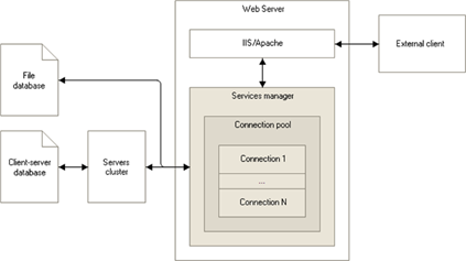
Fig. 485. Web services
Web service clients interact with 1C:Enterprise using web server plug-ins. A web server plug-in runs in the process of the service host, which receives/sends messages to/from the service manager. IIS or Apache web server can be used as a service host.
A web server plug-in contains a connection pool and other mechanisms intended to interact with the 1C:Enterprise database.
The web service mechanism implemented in 1C:Enterprise supports the following standards:
-
SOAP 1.1.
-
SOAP 1.2.
-
WSDL 1.1.
-
WS-I Basic Profile 1.1.
-
HTTP 1.1.
-
TLS 1.x (TLS 1.1 and 1.2 are supported if sending a client certificate to the server is not required), including cryptographic algorithms that comply with GOST R 34.10-94, R 34.10-2001, R 34.10-2012, R 34.11-94, R 34.11-2012, and 28147-89.
-
MTOM.
-
Authentication: Basic, NTLM/Negotiate.
The web service mechanism implemented in 1C:Enterprise does not support:
-
WS-Policy mechanism.
-
WS-Addressing mechanism.
-
WS-Security protocol.
-
Setting the namespace that is already used by XML as a target namespace (targetNamespace).
To access a web service, use the address generated as follows:http://host/base/ws/WebServiceName or http://host/base/ws/WebServiceAddress. Let's consider the address components in more detail:
-
http://host/base. Ordinary URL, for example, used to access an infobase via a web client. If separators are present, specifying separator values using the Z parameter of the command-line for the client application startup is not supported.
-
ws. Indicates that a web service is being accessed (as opposed to hs, which defines access to an HTTP service, see Creating your own HTTP service).
-
WebServicename. Web service name. Set in the Web service object property.
-
WebServiceAddress. Describes an alternative name for accessing the web service. Set in the Publication file name property of the Web service object. Can be changed when publishing web service.
-
Calling the web service name is the same as calling its address.
17.2.2. Providing functions via web services
To make the 1C:Enterprise functions available to external web service consumers, follow these steps:
-
Create the required number of web services in the configuration.
-
Publish web services using a special Designer tool.
To create a web service:
-
Add a web service configuration object to the metadata tree.
-
Describe operations that the web service to create can perform.
-
Describe parameters of web service operations.
The Web service configuration object has a module where you create procedures in 1C:Enterprise language that are executed when calling web service operations. Web service operation parameter types are described using the XDTO types and can be either XDTO values or XDTO objects.
To call a web service:
-
Select the infobase connection from the connection pool. If there is no required connection, create a connection.
-
Create a session and call the SessionParametersSetting event for the created session (in the session module).
-
Call the requested web service method. The SessionParametersSetting() handler is called (in the session module) each time an uninitialized session parameter is accessed.
Note. Tip. It is not recommended that you perform resource-intensive operations in the SessionParametersSetting event handler.
The SessionParametersSetting event of the session module is called on the server in privileged mode. The module of the called service is performed on the server in normal mode.
The session module (see Session module) initializes session parameters and performs some set of commands when calling any 1C:Enterprise web service.
17.2.3. Sample web service implementation
For example, you need to create a 1C:Enterprise web service that has to return the invoice table components using the sent invoice number. For a similar example with HTTP services, seeProcessing documents.
To describe the return value, let's create the InvoiceData XDTO package with the http://www.MyCompany.ru/shipment namespace containing three types of XDTO objects:
-
Products. To send the data of the Products catalog item. This XDTO object type will contain the following properties:
-
Description. The string type from the http://www.w3.org/2001/XMLSchema namespace.
-
FullDescr. The string type from the http://www.w3.org/2001/XMLSchema namespace.
-
Barcode. The string type from the http://www.w3.org/2001/XMLSchema namespace.
-
PurchasePrice. The int type from the http://www.w3.org/2001/XMLSchema namespace.
-
-
InvoiceRow. To send the data of a single invoice row. This XDTO object type will contain the following properties:
-
Products. The Products type from the http://www.MyCompany.ru/shipment namespace. It is a reference to the XDTO object defined above.
-
Count. The int type from the http://www.w3.org/2001/XMLSchema namespace.
-
Price. The int type from the http://www.w3.org/2001/XMLSchema namespace.
-
Sum. The int type from the http://www.w3.org/2001/XMLSchema namespace.
-
-
Invoice. To send the data of all invoice rows. This XDTO object type will contain the only property:
- Content. The InvoiceRow type from the http://www.MyCompany.ru/shipment namespace. It is a reference to the XDTO object defined above. To ensure that this property can have an unlimited number of values, set its Top border property to 1.
After the required XDTO types are created, add new InvoiceData web service with the following properties to the configuration:
-
Namespace URI. http://www.MyCompany.ru/shipment.
-
XDTO packages. InvoiceData.
-
Publication file name. shipment.1cws.
Define the Get operation for the created web service with the following property values:
-
Return value type. Invoice from the http://www.MyCompany.ru/shipment namespace.
-
Possible empty value. Set.
-
Procedure name. Get.
Define the DocumentNumber parameter for the Get operation with the following property values:
-
Value type. The string type from the http://www.w3.org/2001/XMLSchema namespace.
-
Transfer direction. Input.
After that, open the module of the created web service and place the Get() function in this module. This function will be executed when this web service is called.
Function Get(DocumentNumber) Export
// Get an invoice object by
the passed number
DocumentRef = Documents.Invoice.FindByNumber(DocumentNumber, CurrentDate());
If DocumentRef.Empty() Then
Return Undefined;
EndIf;
Document = DocumentRef.GetObject();
// Get XDTO object types
ProductsType = XDTOFactory.Type("http://www.MyCompany.ru/shipment", "Products");
InvoiceType = XDTOFactory.Type("http://www.MyCompany.ru/shipment", "Invoice");
InvoiceRowType = XDTOFactory.Type("http://www.MyCompany.ru/shipment", "InvoiceRow");
// Create an invoice XDTO
object
Invoice = XDTOFactory.Create(InvoiceType);
For Every DocumentLine From
Document.Content Do
// Create XDTO objects of
the invoice row
// and products
InvoiceRow = XDTOFactory.Create(InvoiceRowType);
Products = XDTOFactory.Create(ProductsType);
// Fill product properties
Products.Name = DocumentLine.Products.Name;
Products.FullDescr = DocumentLine.Products.FullDescr;
Products.Barcode = DocumentLine.Products.Barcode;
Products.PurchasePrice = DocumentLine.Products.PurchasePrice;
// Fill invoice row
properties
InvoiceRow.Products= Products;
InvoiceRow.Count = DocumentLine.Count;
InvoiceRow.Price
= DocumentLine.Price;
InvoiceRow.Sum = DocumentLine.Sum;
// Add an invoice row
Invoice.Content.Add(InvoiceRow);
EndDo;
// Return the invoice row
Return Invoice;
EndFunctionFinally, publish the generated web service on a web server, for example, on http://www.MyCompany.ru, in the shipment directory.
17.2.4. Third-party web services
17.2.4.1. General information
1C:Enterprise can use third-party web services:
-
Using static links generated in the configuration tree.
-
Using dynamic links generated with 1C:Enterprise language.
-
Using a combination of the previous methods.
The advantage of using static links is faster operation, because description of the provider's web service is retrieved once when the link is generated. In the future, when you call this web service, the existing description of the web service is used.
When you use dynamic links, the description of the provider's web service will be obtained by 1C:Enterprise each time the web service is called, which will naturally slow down the operation of this web service. However, the advantage of this approach is that you can get the relevant description of the provider's web service. When you use static links to get the relevant description of the web service, reimport the WSDL description using Designer and save the modified configuration.
When you use applications, a situation may arise when the same web service is provided at different addresses (URL), but has the identical description (WSDL). In this case, you need to load the description of the web service into the configuration (create an object in the configuration object tree), but you should give the specific address of the web service while using it. The combined method allows operation in such manner. For example, there is a replicated web service that performs some function. An application written in 1C:Enterprise uses services of this web service, and the address of the service can be different (as the service is replicated), and the description is fixed. Then, you can load the description of the web service into the application and provide for entering the address of a specific service instance in the application settings, which (the address) will be used for operation.
Another example is when a dynamic link is used, but the web service address is not obtained from the description file (WSDL) but is directly specified when the object is created.
When it is attempted to load a web service description in Designer (a static link is generated) or when a dynamic link is used (using the WSDefinitions object), the system checks the web service description (WSDL) to be loaded. If the web service description contains an error (according to 1C:Enterprise), the description will not be loaded and an exception will be thrown. The exception text will contain detailed diagnostics of the reasons for denied loading. WSDL errors are rated according to their disclosure. Each WSDL error contains an entry with a detailed description of the following type:
<Type of the item with the error>.<Name>
[<Type of the item with
the error>.<Name>[…]]
<Error description>
<Type of the item with
the error>
<Name>In this description:
-
Type of the item with the error. Type of the WSDL item. It most often matches the name of the tag in the xml file describing the web service.
-
Error description. Description of the certain error.
-
Name. Name of the WSDL object where the error occurred.
The following table lists errors that may occur when checking a web service description and recommendations for correcting these errors:
| Error description | Correction recommendations |
|---|---|
| No type is found | Check that namespaces and type and element names are correct |
| No message is found | Check that namespaces and message names are correct |
| No binding is found | Check that namespaces and binding names are correct |
| No port type is found | Check that namespaces and port type names are correct |
| No abstract operation is found | Check that the abstract operation name is correct |
| No operation components are found | Specify components in the operation. It may be operation input or output |
| No error description is found | Specify the name of the error description |
| No abstract operation is specified | Specify the abstract operation |
| No name is specified | Specify the WSDL object name according to the schema: [http://schemas.xmlsoap.org/wsdl/2003-02-11.xsd](http://schemas.xmlsoap.org/wsdl/2003-02-11.xsd) |
| Operation input does not match the abstract operation input | The operation and the abstract operation must either have an input (both) or have not it (both). The abstract operation cannot have an input if the operation does not have one, and vice versa. |
| Operation output does not match the abstract operation output | Similar to the message about the operation input |
| No port type is specified | Specify the port type and check namespaces |
| Object is not unique | Check the uniqueness of the object by namespace and name |
| No location is specified | Specify the location R2007 rule: for the import element R2711 rule: for the port element |
| Namespaces are different | Check and correct differences between the import namespaces and the namespace of the imported schema |
| No message part type is specified | Specify the type for the message part (the type or the element according to the WSDL style) and check the namespaces |
| No message is specified | Specify or correct the message name and check the namespace for the WSDL object |
| Abstract operation requires input | Specify input for the abstract operation |
| Abstract operation requires no input | The abstract operation must not have input |
| Abstract operation requires output | Specify output for the abstract operation |
| Abstract operation requires no output | The abstract operation must not have output |
| Abstract operation error is not specified | Specify or check that the abstract error name and the namespace are correct |
| No binding is specified | The port binding is not specified, the binding name is not correct, the namespace is not correct |
| No abstract operation description is specified | The abstract operation description is not specified, the name or the namespace is not correctly specified |
| The operation namespace must be specified in the rpc-literal style | Specify the namespace element for the operation. R2717 rule |
| The operation namespace must be specified in the document-literal style | Delete the namespace element for the operation. R2216 rule |
| The message part in the rpc-literal style must refer to the type definition in the schema | To specify the part type, use the type for the relevant message object in message parts, and not the element (the type tag, not element). R2203 rule |
| The message part in the document-literal style must refer to the element declaration in the schema | To specify the part type, use the element for the relevant message object in message parts, and not the type (the element tag, not type). R2204 rule |
| Unknown binding style | Specify the binding style and check that it is correctly written. Specification: [http://www.w3.org/TR/wsdl#_bindings](http://www.w3.org/TR/wsdl#_bindings). R2705, R2706 rules |
| The binding transport must be specified as [http://schemas.xmlsoap.org/soap/http](http://schemas.xmlsoap.org/soap/http). | The binding transport must be specified as [http://schemas.xmlsoap.org/soap/http](http://schemas.xmlsoap.org/soap/http). R2702 rule |
| No message part is specified | Specify a part of the message to describe the error. R2205 rule |
| In the schema, the header error must be described as an element declaration | Use the type set up as an element (use the element tag) in the part of the message used for the error description. R2205 rule |
| In the schema, the header must be described as an element declaration | Use the type set up as an element (use the element tag) in the part of the message used for the header description. Rule R2205 |
| The schema must contain the targetNamespace attribute | Add the targetNamespace attribute for the schema and fill it in. This requirement is related with features of the platform implementation |
| Cannot load the imported schema | Check that the namespaces and the location of the imported schema are correct |
When you specify an expression of the Rule RXXXX type in the table, it means that you need to find the RXXXX rule in the Basic Profile Version 1.1 specification (http://www.ws-i.org/profiles/basicprofile-1.1-2004-08-24.html).
17.2.4.2. Example of using static WS references
As an example of using third-party web services, let's take a look at calling the web service that was previously created in the example (see Sample web service implementation).
First of all, add the new WS reference configuration object to the configuration tree named GoodsReceiptData that refers to the published service. To do this, import the WSDL description of the published service and specify http://www.MyCompany.ru/shipment/ws/Shipment.1cws?wsdl as a URL. For WSDL description import, see Adding WS reference.
After that, you can generate the procedure given below, for example, in the goods receipt module. It fills the document table with the data of the provider's goods receipt received using the provider's web service.
Procedure GetGoodsReceiptData(ProviderReceiptNumber)
// Generate a WS proxy
server based on the reference
Proxy = WSReferences.InvoiceData.CreateWSProxy("http://www.MyCompany.ru/shipment", "InvoiceData", "InvoiceDataSoap");
GoodsReceiptData = Proxy.Get();
If GoodsReceiptData = Undefined Then
Return;
EndIf;
// Fill the goods receipt
with the received data
For Every GoodsReceiptRow
From GoodsReceiptData.Content Do
NewRow = DocumentObject.Content.Add();
NewRow.Count = GoodsReceiptRow.Count;
NewRow.Price = GoodsReceiptRow.Price;
NewRow.Sum = GoodsReceiptRow.Sum;
// Find the product item
according to the passed data
// (for example, according
to a barcode)
NewRow.Products = Catalogs.Products.FindByAttribute("Barcode", InvoiceRow.Products.Barcode);
EndDo;
EndProcedureIf the address of the service's actual location is different from the address used when the web service description was loaded into the configuration, explicitly specify the new address when creating the WSProxy object:
// Generate a WS proxy server based on the reference
Proxy
= WSReferences.InvoiceData.CreateWSProxy("http://www.MyCompany.ru/shipment", "GoodsReceiptData", "GoodsReceiptDataSoap", , , , "http://www.realURL/realPath");17.2.4.3. Example of using dynamic WS references
Using a dynamic reference is different from using a static reference only in the way the WS proxy server is generated and that there is no need to create a WS reference in the configuration tree.
Compared to the example given in the previous section, so, unlike generating a proxy server based on a static reference, when using a dynamic reference, a WS proxy server is generated using the constructor as follows:
// Generate a WS proxy server based on the WS definition
Definition = New WSDefinitions("http://www.MyCompany.ru/shipment/ws/Shipment.1cws?wsdl");
Proxy
= New WSProxy (Definition, "http://www.MyCompany.ru/shipment", "InvoiceData", "InvoiceDataSoap");While generating a WS proxy server based on a static reference looks as follows:
// Generate a WS proxy server based on the reference
Proxy
= WSReferences.InvoiceData.CreateWSProxy("http://www.MyCompany.ru/shipment", "InvoiceData", "InvoiceDataSoap");If the address of the service's actual location is different from the address specified in the WSDL file used to generate the web service definition, explicitly specify the new address when the WSProxy object is generated based on the web service definition:
// Generate a WS proxy server based on the WS definition
Definition = New WSDefinitions("http://www.MyCompany.ru/shipment/ws/Shipment.1cws?wsdl");
Proxy
= New WSProxy (Definition, "http://www.MyCompany.ru/shipment", "GoodsReceiptData", "GoodsReceiptDataSoap", , , , "http://www.realURL/realPath");17.2.5. Editing web service properties
On the Main tab, enter the object name, synonym, and comment.
On the Operations tab, create subordinate Operations objects, which, in turn, can have subordinate Operations objects needed to operate objects of this type. Subordinate objects are described in the property palette.
17.2.5.1. "Operations" properties
Apart from the general properties of configuration objects, a web service operation contains the following properties:
-
Return value type. Type of the value returned by the web service operation. It may be either an XDTO value type or an XDTO object type.
-
Possibly empty value indicates whether the return value can be undefined.
-
In transaction. Indicates whether the web service module code will be executed in a transaction. If the property is set, the transaction will automatically start when the web service is called. The transaction will be either committed or rolled back (depending on the execution results) when the web service operation is completed. If the property is not set, the transaction will not start when the web service module starts executing.
-
Method name. Name of the exported web service module procedure that will be completed when this property is called.
The Subsystems tab specifies which subsystems the objects of this type belong to.
The Other tab determines the following properties:
-
Namespace URI. Contains web service namespace URI. Each web service can be uniquely identified by its name and the URI of the namespace to which it belongs. The service namespace must not be the same as known namespaces that are already used or reserved by other companies. It is recommended that you include the fragment unique for the company that develops the web service in the service. namespace. For example, it makes sense to start all namespaces with a prefix for a company named Promresurs, for example, http://promresurs.com. Then the web service namespace URI will be http://promresurs.com/public/services/OurService.
-
XDTO packages. List of XDTO packages whose types can be used as return value types for web service operations and operation parameter types.
-
Publication file name. Name of the web service description file located on the web server.
To open the web service module editor, click the Module button.
17.2.5.2. "Parameter" properties
Apart from the general properties of configuration objects, a web service operation parameter contains the following properties:
-
Value type. Value type of the web service operation parameter. It may be either an XDTO value type or an XDTO object type.
-
Possibly empty value indicates whether the operation parameter value can be undefined.
-
Transfer direction determines the data transfer direction using this parameter. Values:
-
Input. Means that the parameter is used to transfer data to the web service.
-
Output. Means that the parameter is used to get data from the web service.
-
Input-Output. Means that the parameter can be used both to transfer data and get to/from the web service.
-
17.3. HTTP services
17.3.1. Using HTTP services
17.3.1.1. General information
HTTP services (and REST APIs) can provide not only systems created on 1C:Enterprise platform, but any systems available on the Internet. REST interface is generally associated with a client/server interaction. On the server side, some API (REST interface) used by the client (1C:Enterprise configuration) is implemented. To receive data, the client uses HTTP requests. The requests and server responses to them are sent via HTTP.
To review HTTP services, we will use the following concepts:
-
Resource is any information that can be received when accessing REST interface.
-
URI stands for Uniform Resource Identifier. In fact, it is the network address access to which will result in an action.
-
Request is similar to the function call. To execute an action, send a request to the required resource. Some HTTP request variants are called "methods". You can define your own request variants. Standard HTTP request methods are given here: https://datatracker.ietf.org/doc/html/rfc7231#section-4 or here: https://developer.mozilla.org/ru/docs/Web/HTTP/Methods. Using HTTP requests, you can implement a database operating concept similar to CRUD:
-
Create. Create a record in the database. For HTTP requests, the POST method is used.
-
Read. Read the record from the database using the GET method.
-
Update. Update the record in the database using the PUT method.
-
Delete. Delete the record from the database using the DELETE method.
-
The correspondence above is not the only possible one. For example, the used server will require the PATCH method instead of the PUT method to change data.
- Status code (or response code) is a number that the client can use to define the request result and identify further required actions. Status code is a 3-digit integer generated according to special rules. Standard status code description is given here: https://datatracker.ietf.org/doc/html/rfc7231#section-6 or here: https://developer.mozilla.org/ru/docs/Web/HTTP/Status.
Therefore, the general procedure is as follows:
-
The client establishes an HTTP connection with the server.
-
The client executes a request of a certain type to a resource with a specific ID.
-
The server processes the request, generates a response and a status code.
-
The response and status code are returned to the client.
-
The client analyzes the status code and processes the response body if required.
During client/server interaction, messages that consist of the following parts are used:
-
Start line defines the message type. The start line also indicates which HTTP request method is transferred in this message.
-
Headers are various auxiliary parameters for internal purposes. Each header is a key-value pair. Standard headers are described here: https://www.iana.org/assignments/message-headers/message-headers.xhtml or here: https://developer.mozilla.org/ru/docs/Web/HTTP/Headers.
-
Message body, if present, is used to transfer free-form data related to the request or response. Whether a message body is required is determined by the used method and its applied implementation on the server side. The format of the message body content is not standardized.
1C:Enterprise provides a specific set of objects that allows the developer to execute all of the actions above:
-
HTTPConnection establishes connection with instant messaging system and executes HTTP requests to this system.
-
HTTPRequest describes HTTP requests sent via the HTTPConnection object. It allows you to set the requested resource address, headers and the request body.
-
HTTPResponse provides access to the response content generated by the server as the result of HTTP request processing.
This way, the developer does not have to manually specify the message text. It is enough to use the object model, and 1C:Enterprise platform will automatically generate the message body according to the used standards and send it to the server. The response message will be automatically converted to the corresponding object when receiving a server response.
Depending on where the HTTP request is processed, 1C:Enterprise provides two operation modes:
-
Synchronous mode is available only on 1C:Enterprise server side.
-
Asynchronous mode is available only on the client application side. Operation on the web client side imposes additional restrictions that depend on the web browser and adopted security model. They will be specified in the description of a method in the Syntax Assistant. In contrast to a synchronous method, an asynchronous method has the Async suffix at the end of its name: CallHTTPMethod() is a synchronous method, CallHTTPMethodAsync() is an asynchronous method.
17.3.1.2. General operational scheme with HTTP requests
To use HTTP requests, create an HTTP connection with a resource to use. Use the HTTPConnection object for that. In our examples, we will use the http://httpbin.org website (source service code: https://github.com/postmanlabs/httpbin). The website provides a simple REST interface to check your code. You can also use the https://reqres.in/ service. All the examples will be processed on the client application side. Therefore, the asynchronous mode will be used for them.
For example, you can create the HTTPConnection object as follows:
Connection
= New HTTPConnection("httpbin.org", , , , , 5);This example shows a connection with the http://httpbin.org server and a 5 second timeout for performing actions with the server. In this example, pay attention to the following points:
-
In the server address, you do not need to specify the access scheme to the server (HTTP or HTTPS) and the path on the server (resource ID). To specify the access scheme, use the SecureConnection wizard parameter. The resource ID will be specified when creating an HTTP request. When you create an HTTP connection, specify the server address.
-
To access the server, use the standard port 80. If the server requires a different port, use the Port parameter.
-
To access the test server, you do not need to specify a username and password on the server. Therefore, the User and Password wizard parameters of the HTTP connection are not specified. If the server authenticates the user, use the parameters.
-
To access the server, proxy server parameters are used by default. If the proxy server requires a username and password, create the InternetProxy object and fill the required object parameters. Proxy server is an intermediate server that redirects HTTP traffic. Proxy servers are used to improve request execution by caching web pages. They are also used to manage HTTP traffic (for example, to lock access to some resources) and the firewall.
-
This example demonstrates regular unsecure connection.
This way, by executing this program code, we will create an HTTP connection to the server. We will use this connection later to access the server.
Now we need to execute the GET request to the /get resource of the used server. The request does not have any parameters. You can do it as follows:
Request = New HTTPRequest("/get");
PromisedResult = Connection.CallHTTPMethodAsync("GET", Request);
Result
= Await PromisedResult;This example shows the asynchronous GET request to the used server. Note the following aspects of the example:
-
The request will be executed asynchronously. Since it is an asynchronous request, the developer can implement another code after sending the request to the server and it will be executed while the HTTP request to the server is being executed.
-
The request must be executed in no more than 5 seconds. This is the timeout that was set for the HTTP connection used to execute our request. If you need to change the timeout, use the Timeout parameter of the HTTPConnection object constructor.
If there are no infrastructure errors that can lead to exceptions, the Result variable will be a value of the HTTPResponse type. You can analyze the request execution result after getting the response.
First, check the request execution status. To do this, use the StatusCode property of the HTTPResponse object. If the property value is set to 200, the request execution is successful. In this case, you can analyze the response body if the server has returned some data in the response body.
If Result.StatusCode = 200 Then
// success
Else
// something went wrong
EndIf;If the status code is different from 200 (from 2XX code folder in general), the request execution is unsuccessful. However, if the status code is not 2XX, it does not mean that the request was executed with an error. For example, the server informs you that you need to specify a different URI to execute the request as the resource uses redirection. Status codes of the 3XX folder will inform you about it. In this case, the application code must analyze response headers and receive information from them on how to execute the request again.
To analyze server response headers, we need the Headers property of the HTTPResponse object. This property contains a map. Each map item is one item of the server response message header. The following example will output all headers available in the server response:
For Each Header In Result.Headers Do
Message("" + Header.Key + " = " + Header.Value);
EndDo;When you send a request, you might need to fill message headers. To do this, you can use the Headers property of the HTTPRequest object. This property is also a map. For example, if you need the server to return a response in JSON format, set the Content-type header as follows:
Request.Headers.Insert("Content-type", "application/json");It only makes sense to do this if the server analyzes the header and allows returning a response in several different formats. Note that the return value format can be defined not only by the message header but also by the request parameters.
Request parameters are set when you generate the HTTP request object. Request parameters (unlike request headers) are processed directly by the server application code. Such parameters are of applied nature. Request parameters are described by the key-value pair and specified in the resource ID text. The list of parameters is separated from the URI by a question mark "?". The parameters are separated by an ampersand "&".
The HTTP service can receive parameters both as URI and as request parameters. For example, if you need to get a document with a number, you can use the following methods (here is a full URI for the GET request to a mythical service):
-
http://my.example.com/documents/16: get a document whose number is 16.
-
http://my.example.com/documents&id=16: get a document whose number is 16.
How a particular service receives parameters depends entirely on its implementation and approaches of its developers. HTTP request generation will be almost the same:
Request = New HTTPRequest("/documents/16");
Request
= New HTTPRequest("/documents?id=16");If we consider URI generation and definition of request parameters from the business logic point of view, we can conditionally divide them as follows:
-
If something is included in the URI, it is most likely a business entity (documents, users, and so on).
-
If something is included in the request parameters, it is most likely a filter for objects of the used business entity. For example, only posted documents or only external users.
In the example above, a generic method to execute any HTTP request is used: CallHTTPMethodAsync(). An executed method and request description are specified in this method. However, if you decide not to use this generic method for some reason, you can use a set of specialized methods that are also provided by the HTTPConnection object. These methods of the HTTPConnection object allow you to execute only some HTTP requests:
| HTTPConnection object method | HTTP method |
|---|---|
| DeleteAsync() | DELETE |
| GetAsync() | GET |
| HeadAsync() | HEAD |
| PatchAsync() | PATCH |
| PostAsync() | POST |
| WriteAsync() | PUT |
In conclusion of this section, let us cover request body operations. As already noted, the request body content and format are determined by the interface provided by the REST service for which we write the program code. However, 1C:Enterprise provides several generic methods to access the request body:
-
Use request body as a string:
-
HTTPRequest: GetBodyAsString()/SetBodyFromString().
-
HTTPResponse: GetBodyAsString().
-
-
Use request body as binary data:
-
HTTPRequest: GetBodyAsBinaryData()/SetBodyFromBinaryData().
-
HTTPResponse: GetBodyAsBinaryData().
-
-
Use request body as a stream:
-
HTTPRequest: GetBodyAsStream().
-
HTTPResponse: GetBodyAsStream().
-
-
Use a file as a request body:
-
HTTPRequest: GetBodyFileName()/SetBodyFileName().
-
HTTPResponse: GetBodyFileName().
-
This way, if some request returns as a result a request body that contains data in JSON format, the following example of 1C:Enterprise language code will return a map that contains response body data (in the Data variable):
Reader = New JSONReader;
Reader.SetString(Result.GetBodyAsString());
Data = ReadJSON(Reader, True);
Reader.Close();Similarly, you can generate the body of HTTP requests to the used service.
17.3.1.3. Operating over a secure connection
In the previous section, we have reviewed how to use HTTP requests over an HTTP connection. Since this connection is unsecure, transferring sensitive data over it is not a good idea. In this case, use a secure HTTPS connection. Let us consider what needs to be changed to use HTTP requests in a secure connection.
To use a secure connection for operations with HTTP requests, specify the SecureConnection parameter value of the HTTPConnection constructor. This parameter can have the OpenSSLSecureConnection or CryptoProSecureConnection item value. Depending on the used item a library of cryptographic service providers OpenSSL or CryptoPro will be used.
//SecureConnection = New CryptoProSecureConnection(,
OSCertificationAuthorityCertificates);
SecureCOnnection = New OpenSSLSecureConnection(OSCertificationAuthorityCertificates);
Connection
= New HTTPConnection("httpbin.org", , , , , 5, SecureConnection);This is the only change to be made. Note the following properties that will change in the properties of the HTTPConnection object if the connection is established over HTTPS:
-
The SecureConnection property is set to the OpenSSLSecureConnection (as in the example above) or CryptoProSecureConnection value type. For a regular connection, this property is set to Undefined.
-
The Port property is set to 443 (the default port for an HTTPS connection). For a regular connection, this property is set to 80. If the port is explicitly specified in the constructor, the Port property will contain an explicitly specified value.
When you create the SecureConnection object, you can control where the client certificate will be received from (the ClientCertificate property) to establish the connection. You can also control where the certificate authority certificates will be received from. These certificates will be used for server certificate validity check (the CertificationAuthorityCertificates property). It is also possible to control the behavior of the system when the certificate revocation checking server is unavailable (the ServerTLSCertificateRevocationCheckMode property).
The client certificate location depends on the value of the ClientCertificate property or respective constructor parameter:
-
Undefined. In this case, connection will be established only if the server does not require the client certificate.
-
CryptoCertificate. Client certificate is obtained from binary data or a file. You can obtain value of this type as a result of searching for a certificate (using various criteria) in the cryptography certificate store (family of FindBy* methods of the CryptoCertificateStore object).
-
FileClientCertificate. The client certificate and private key are located in the file specified upon creation of the FileClientCertificate object.
-
OSClientCertificate. In this case, the client certificate is received from the system storage of the operating system where the code is executed in 1C:Enterprise language. This is the recommended way of certificate store specification when writing a cross-platform code.
-
LinuxClientCertificate, MacOSClientCertificate, and WindowsClientCertificate. The client certificate is located in the system storage of the corresponding operating system.
If the client certificate is selected in the OS system certificate store and several suitable certificates are found, set the certificate selection method using the *CertificateSelectMode parameter for the WindowsClientCertificate, MacOSClientCertificate, and OSClientCertificate objects.
To specify location of the certificate authority certificates used for server certificate validation, use the CertificationAuthorityCertificates property and respective constructor parameter:
-
Undefined. In this case, HTTPS connection is established without server certificate validation.
-
FileCertificationAuthorityCertificates. Certificate authority certificates are used for server certificate validation. They are located in the file specified upon creation of the FileCertificationAuthorityCertificates object.
-
OSCertificationAuthorityCertificates. In this case, to validate the server certificate, use the system certificate stores of the certificate authority of the operating system where 1C:Enterprise language code is executed. This is the recommended way of certificate store specification when writing a cross-platform code.
-
LinuxCertificationAuthorityCertificates, MacOSCertificationAuthorityCertificates, and WindowsCertificationAuthorityCertificates. In this case, to validate the server certificate, use the system certificate stores of the certificate authority of the corresponding operating system.
The ServerTLSCertificateRevocationCheckMode property (or the corresponding constructor parameter) controls the behavior of the system when the revocation check of the supplied server certificate cannot be verified. The parameter can only take a value of the ServerTLSCertificateRevocationCheckMode system enumeration:
-
Auto. In this case, the system behavior is determined by the IgnoreServerCertificatesChainRevocationSoftFail parameter of the conf.cfg configuration file. With default settings, the behavior will be compliant to the SoftFail value of the enumeration. If the parameter is not specified this value will be used.
-
Strict. If certificate revocation cannot be checked, an exception will be thrown, and connection will not be established.
-
SoftFail. If server certificate revocation cannot be checked, connection will be established.
-
DontCheck. Server certificate revocation is not checked.
Do not use a server certificate that is not checked for revocation in industrial systems. This may lead to security problems.
17.3.1.4. Using JWT authentication
17.3.1.4.1. General information
Token is a tool to authenticate a user, a group of users, or a separate session in the application. JSON Web Token (JWT) is a standard for access token creation based on JSON format. JWT is described in the RFC 7519 standard (https://datatracker.ietf.org/doc/html/rfc7519). JWT is used for user authentication in client/server applications. The use of JWT can be described as follows:
-
A user is authenticated on the authentication server, for example, using a username and password.
-
The authentication server provides the user with a JWT as a response.
-
The user accesses the application by providing the JWT obtained at the previous step.
-
If the provided JWT is successfully verified, the application performs the requested action and returns a result.
Let us briefly review JWT and how this tool can be used in 1C:Enterprise.
JWT consists of three parts: header, payload, and signature. Header and payload are objects in JSON format. The header contains internal information that allows the verifying party to process the JWT data correctly. Payload consists of JWT claims. They describe the application data required for the application that performs authentication (executes a request authenticated via JWT). Standard claim names are listed in section 4.1 of RFC 7519. The developer can create their own claim name. Claim names must be unique within one token.
The signature is generated based on the header and payload using a special function described in the header and converted to Base64URL format. JWT is a dot-separated string that consists of three parts. The header and payload are also encoded using the Base64URL algorithm.
Consider an example.
The header contains the following information:
{
"alg": "HS256", "typ": "JWT"
}The payload contains the following information:
{
"id": "1234567890", "name": "John Smith", "role": "administrator"
}JWT will look as follows:
eyJhbGciOiJIUzI1NiIsInR5cCI6IkpXVCJ9. eyJpZCI6IjEyMzQ1Njc4OTAiLCJuYW1lIjoi0JjQstCw0L0g0JjQstCw0L3QvtCyIiwicm9sZSI6ImFkbWluaXN0cmF0b3IifQ. n-0muDfzGhlMQbzaCxeIU8JItoN1Yr4RdJq4G8RUnckEach dot-separated part of the JWT in the example is displayed in a separate line for readability. If the second line (starting with "eyJpZCI6I") does not fit entirely the line width of your documentation viewer, the example will be displayed in more than 3 lines.
Obviously, there is a direct correlation between the JWT size and the amount of information included in the payload section.
JWT can be used in 1C:Enterprise in the following cases:
-
As one of authentication methods for 1C:Enterprise infobase users.
-
As one of authentication methods when using HTTP- and web services.
-
When setting up infobase publication on the web server.
To experiment with different JWTs, you can go to https://jwt.io.
17.3.1.4.2. Generating JWTs programmatically
To create a JWT programmatically, use the AccessToken object. The string presentation of a value instance of this type will be a JWT text (in Base64URL format). You can use the resulting string when a remote system requires you to specify a JWT as a method parameter or a startup command-line parameter value.
To specify a token header, use the Headers property of the AccessToken object. This header contains a map where each map item describes one header parameter. The map item key is the parameter name and the parameter value is written to the map item value. To generate a correct token, always set the typ and alg headers. If a JWT is generated for use by 1C:Enterprise platform, the typ header can only take the JWT and JWS values. The AccessTokenSignAlgorithm system enumeration contains supported signature generation algorithms. It is not recommended that you disable JWT signature usage. The alg header set to the none value disables the signature and does not allow you to check the JWT source.
To generate a payload, in the AccessToken object, use the Payload property, which allows you to set any claim. In addition, there are several claims whose values can be changed using properties of the AccessToken object. In the table below, you can see properties of the AccessToken object and respective claims:
| Object property | Name and brief description of the claim |
|---|---|
| LifeTime | exp. Time in Unix format (the number of seconds that have passed since 01/01/1970) that defines when the token expires. |
| CreationTime | iat, nbf. Time in Unix format (the number of seconds that have passed since 01/01/1970) that defines the moment of token creation (iat) and its validity period start (nbf). When the CreationTime property is changed, 1C:Enterprise changes both claims at the same time. If you need to fill the iat and nbf claims with different values, use the Payload property. |
| ID | jti. UUID of the generated token. |
| UserMatchingKey | sub. UUID of the subject for which the token is generated. It must be unique within the system that serves the request. This claim contains a username on whose behalf the action in the application will be performed. |
| Recipients | aud passed as an array. UUID list of applications for which this token is generated. If the current application is not in this list, the token must be ignored. |
| Issuer | iss. ID of the application that issued a token. |
If you change the claims using object properties and a claim collection, note the following rules:
-
If you change properties of the AccessToken object, it automatically creates or changes the corresponding claim.
-
If you change a named claim, the linked property of the AccessToken object is not changed.
A simple conclusion follows from these rules: for payload manipulations, use either specific properties of the AccessToken object (listed in the table above) or the Payload property. Using both object properties and names of specific claims (from the RFC 7519 standard) at the same time can lead to unexpected consequences. It is recommended that you use the Headers and Payload properties when the interface of the AccessToken object is not enough to generate a JWT for a certain used service.
Therefore, to generate a JWT, you can use this code in 1C:Enterprise language:
SignAlgorithm = AccessTokenSignAlgorithm.HS256;
AccessToken = New AccessToken;
AccessToken.Headers.Insert("alg", String(SignAlgorithm));
AccessToken.Issuer = "ERP";
AccessToken.Recipients.Add("UPTO8");
AccessToken.UserMatchingKey
= "JohnSmith";
AccessToken.CreationTime
= CurrentUniversalDate() - Date(1970,1,1,0,0,0);
AccessToken.LifeTime = 3600;
AccessToken.ID = New UUID;
AccessToken.SignAsync(SignAlgorithm, SignKey);
TokenText = String(AccessToken); // get a token as a string17.3.1.4.3. Using JWT
If the server to which a HTTP request is executed requires JWT specification, you can do it in several different ways. However, technically, all possibilities rely either on HTTP request header generation or request parameter generation.
The simplest way is to explicitly specify the bearer token in the Authorization header of the HTTP request to the server:
Request = New HTTPRequest("/get");
Request.Headers.Insert("Authorization", "Bearer" + TokenText);A similar header will be generated if you use the AddAccessToken() method of the HTTPRequest object. The difference with the previous way is that the method parameter is not a string, but a value of the AccessToken type:
Request = New HTTPRequest("/get");
Request.AddAccessToken(AccessToken);If the server requires an access token as a request parameter, you can do it as follows:
Request = New HTTPRequest("/get?AccessToken=" + TokenText);If you need to pass an access token when you start 1C:Enterprise client application, use the startup command line. The AccessToken command passes a JWT in text form to the client application. For this action to make sense, access token authentication must be enabled for infobase users.
See also:
-
Infobase user parameters.
-
default.vrd file.
-
Startup command line for 1C:Enterprise client application.
-
Command line of web client startup.
17.3.2. Creating your own HTTP services
17.3.2.1. General information
You can access an HTTP service implemented in the application using a URL. As an example, an HTTP service returns a list of some documents (for example, invoices) when accessed by one URL. When accessed by another URL, it returns a particular invoice. The action to be executed by the server is determined by the HTTP method addressed to the server. For example, if a GET request is sent to the server, some data is received, a DELETE request deletes some data, and so on.
When implementing an HTTP service, the application developer defines the following service items:
-
Base part of the URL that will be used to access the service.
-
Supported functions and structure of resources to which these functions will be applied.
-
Actions (HTTP methods) that can be executed when accessing a resource.
-
Each chosen action implies implementing a specialized method, described in the 1C:Enterprise language, which implements the required functions. The method is located in a special module associated with the HTTP service.
Once you have implemented the HTTP service, publish it to a web server using the standard publishing mechanism.
When you access the HTTP service, a URL is generated, which looks as follows: http://host/base/hs/rootURL/relativeURL. Let's consider the address components in more detail:
-
http://host/base. Ordinary URL, for example, used to access an infobase via a web client. If separators are present, specifying separator values using the Z parameter of the command-line for the client application startup is not supported.
-
hs. Indicates that an HTTP service is being accessed (as opposed to ws, which defines access to a web service).
-
rootURL. Resource name that defines a group of resources related in a common sense. Defined in the HTTP service object property.
-
relativeURL. Determines the resource to be accessed. The relative URL specified in the request will be used to determine the specific resource being accessed. The matching rule is specified in the URL template object.
17.3.2.2. Developing HTTP services
To create HTTP services, in the configuration object tree, click General – HTTP services. First, create the service itself, then create a specific URL fragment template (resource group) for each service, and then define the HTTP method for each resource group, which will be implemented for this group. Note that one service can include more than one URL template (a one-to-many relationship). In fact, the URL template defines a group of resources processed according to the same rules.
17.3.2.2.1. Editing HTTP services
When creating a HTTP service, pay attention to the Root URL property. It defines a group of resources united by the overall sense. For example, if you need to create a few resources that process orders, the root URL may look as order in this case. When you access this service, the beginning of the URL will look as follows: http://host/base/hs/order.
17.3.2.2.2. Editing URL templates
When creating a URL template, specify possible resource addresses that can be used to access the HTTP service. The template itself is det in the Template property. When creating a template, you can use the following characters:
-
Any characters allowed in 1C:Enterprise language IDs
-
"/"
-
"{}" with non-empty text between these characters
-
"*"
For example, the template may look as follows:
/query
/documents/{id}/props/{PropertyName}/*When describing the template, the following terms will be used:
-
Segment. Part of the URL between two "/" characters. For example, props from the example above is a segment.
-
Parameter-based segment. Segment enclosed in curly brackets ("{segment}"). In fact, the parameterized segment describes a variable with the name specified, which can be accessed from 1C:Enterprise language.
The segment (not parameterized) from the template must be passed to the URL word-for-word. The parameterized segment can be replaced with any value allowed in the URL. "" can only appear at the end of a template. Any number of segments can be in place of "", including the absence of a segment. One template cannot contain parameterized segments with the same name. The parameterized segment can only consist of letters, digits, and the "_" character.
The /documents/*/number template type is not acceptable. If the /documents/{kind}/{number} template type is set, the following service URLs are valid:
/documents/trade/13
/documents/12/testUpon request receipt, the application tries to determine which template to use. For this purpose, the application attempts to match the incoming request text with the templates set. The matching is performed according to the following rules:
-
All lines are matched case-sensitively.
-
An exact match is always a higher priority than matching with the template with parameterized segments or the "*" character.
-
The "*" character can be matched with any number of segments (including no segment).
-
A parameterized segment is a higher priority than the "*" character.
-
If the passed request fails to uniquely match any template, an error will be generated.
The following examples illustrate these rules:
-
While matching the /Invoice URL with the /Invoice/ and /{EntityName}/ templates, the first template will be selected for use.
-
The /Document/*/{Num} template is not valid.
-
The /Invoice/500/Rows/2/Product URL can be matched with the /Invoice/* template.
-
While matching the /Invoice/500 URL with the /(Document)/{Num} and /{Document}/* templates, the first template will be selected for use.
-
While matching the /Invoice/500/ URL with the {Document}/{Num} and /{Document}/{Number} templates, an error will occur because the template could not be uniquely selected.
17.3.2.2.3. Editing methods
For the created template, define HTTP methods. You can use them for processing a resource that matches the template. To do this, create the required number of Method objects subordinate to the URL template object. Specify the HTTP method property in each method and create a handler. The handler name is automatically generated from the URL template name and the actual method name. Thus, if the ExampleForDocumentation name is specified in the URL template and the GET name is specified for the method, then the ExampleForDocumentationGET() handler name will be used for the 1C:Enterprise language method that will process the HTTP request.
Note. Tip. It is recommended that you name HTTP method objects with the name of the serviced method in English.
You can create handlers for the following methods:
-
GET
-
POST
-
PUT
-
DELETE
-
PATCH
-
MERGE
-
CONNECT
-
OPTIONS
-
TRACE
-
PROPFIND
-
PROPPATCH
-
MKCOL
-
COPY
-
MOVE
-
LOCK
-
UNLOCK
If you create a handler for the Any method, then the handler of this method will be called for all HTTP methods (from the above list) that are not explicitly described in the template that "processes" the incoming HTTP request.
After the required template is received, an attempt will be made to call the method servicing the required HTTP request (GET, POST, and so on). If no handler of the required request is found, a 405 error will be returned to the caller. If a 1C:Enterprise language error is found during method execution, a 500 error will be returned to the caller, and the exception text will be placed in the response body.
When generating a response, the Content-Length parameter may not be specified. In this case, it will be defined automatically.
17.3.2.2.4. Method handler inputs and outputs
The handler of any HTTP method is a function that gets one parameter of the HTTPServiceRequest type as input and must return an object of the HTTPServiceResponse type.
The input parameter fully describes the received request. With the object, you can define:
-
Which HTTP method is used in the request (the HTTPMethod property).
-
Which URL received the request (the BaseURL property). Part of the full URL of the request, not including the relative URL (see General information) and the request parameters.
-
Relative URL (the RelativeURL property). Part of the full URL of the request that was used to define the resource group and the rules for processing the incoming HTTP request.
-
Which headers (the Headers property) the HTTP request contains.
-
Which parameterized segments (the URLParameters property) are separated from the incoming HTTP request and their values.
-
Which parameters (the QueryOptions property) are listed in the HTTP request URL after "?" and their values.
You can also receive the request body as binary data or a string (depending on the information passed).
Thus, the application developer does not have to "deal with" the incoming request on their own. Using the example later in this chapter (see Displaying incoming requests), you can see how an incoming HTTP request is distributed between the HTTPServiceRequest object properties.
After the application has executed all the actions defined for this resource and the HTTP method, generate a service response. To do this, create an object of the HTTPServiceResponse type. Depending on the processing result, specify the StatusCode property that describes the standard HTTP return code: https://datatracker.ietf.org/doc/html/rfc2616#section-10. Then, if necessary, generate the HTTP service response body. The body can be set as binary data, as a string, or by specifying the file name to load the response body from. If the value type returned by the function (which implements the response to the HTTP method) is different from HTTPServiceResponse, then a 500 error will be returned to the client.
17.3.2.3. HTTP service implementation examples
Note. Note. The examples below are not complete. They are intended for demonstrating some capabilities of HTTP services.
17.3.2.3.1. Displaying incoming requests
As an example, let's implement an HTTP service that will return all incoming request parameters as a response.
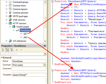
Fig. 486. Text example
To do this, create theOperationExample HTTP service and specify the example root URL for it. Then create the ShowRequest URL template with the /query/{string}/* template. Now add the following methods to the ShowRequest template:
-
GET method for the HTTP GET request.
-
ANY method for the HTTP Any request.
Handlers must look as follows:
Function ShowGETRequest(Request)
Response = New HTTPServiceResponse(200);
Result = "";
Result = Result + Request.HTTPMethod + Chars.LF;
Result = Result + Request.BaseURL + Chars.LF;
Result = Result + Request.RelativeURL + Chars.LF;
Result = Result + "Headers:" + Chars.LF;
For Every Parameter From
Request.Headers Do
Result = Result + Parameter.Key + ":" + Parameter.Value + Chars.LF;
EndDo;
Result = Result + "Parameters URL:" + Chars.LF;
For Every Parameter From
Request.URLParameters Do
Result = Result + Parameter.Key + ":" + Parameter.Value + Chars.LF;
EndDo;
Result = Result + "Request parameters:" + Chars.LF;
For Every Parameter From
Request.QueryOptions Do
Result = Result + Parameter.Key + ":" + Parameter.Value + Chars.LF;
EndDo;
Response.SetBodyFromString(Result);
Return Response;
EndFunction
Function ShowANYRequest(Request)
Response = New HTTPServiceResponse(405);
Response.SetBodyFromString("This
HTTP service does not support the method " + Request.HTTPMethod);
Return Response;
EndFunctionAfter publishing HTTP services, the service must return the full "description" of the incoming request.
When you use the following request: http://localhost/httpservice/hs/example/query/value/another?p1=1&p2=2, the following response will be received (the value of some headers depends on the web browser being used):
GET
http://localhost/httpservice/hs/example
/query/value/another
Headers:
Accept Encoding:gzip,deflate,sdch
Connection:keep alive
Accept Language:ru RU,ru;q=0.8,en US;q=0.6,en;q=0.4
DNT:1
Accept:text/html,application/xhtml+xml,application/xml;q=0.9,image/webp,*/*;q=0.8
Content Length:0
User Agent:Mozilla/5.0 (Windows NT 6.1; WOW64) AppleWebKit/537.36
(KHTML, like Gecko) Chrome/32.0.1700.107 Safari/537.36
Host:localhost
URL parameters:
*:/another
string:value
Query parameters:
p1:1
p2:2Let's see how the request was parsed. The example specified that the root URL of the service was example, the URL template was /query/{string}/*, and a GET HTTP request handler was generated.
You can see from the result that the following URL parameters have been defined:
-
Parameter * with the /another value.
-
Parameter string with the value value.
This fully matches the specified URL template. If the URL template is set to /query/{string}, then the demo request will end with a 404 error message, as this template will not allow information in the URL after the parameterized segment.
The method handler will also pass all request parameters that were specified in the URL.
Any other request type (other than GET) will result in a 405 error indicating which request is not supported by the service.
17.3.2.3.2. Processing documents
This example is an analog of a web service that must return the table components of the invoice based on its passed number (see Sample web service implementation).
This example will provide the ability to get a list of "documents" and get a "document" by number. A reaction to an incorrect "document" number will also be implemented. To simplify the example, real objects of the Document type will not be created in the example.
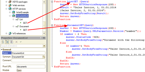
Fig. 487. Text example
To do this, create the DocumentList HTTP service and specify the documents root URL for it. Then create the List URL template with the /* template and the Document URL template with the /{number} template. You should the method GET implementation for each URL template.
Handlers must look as follows:
Function ListGET (Request)
Response = New HTTPServiceResponse(200);
Result = "Invoice, 1, 01/01/2014
|Invoice, 2, 01/01/2014";
Response.SetBodyFromString(Result);
Return Response;
EndFunction
Function DocumentGET(Request)
Response = New HTTPServiceResponse(200);
Number = Number(Request.URLParameters.Get("number"));
If Number> 2 Then
Response.StatusCode = 404;
Response.SetBodyFromString("No
document with the following number: " + Number);
Else
If Number=1 Then
Response.SetBodyFromString("Invoice, 1, 01/01/2014");
Else
Response.SetBodyFromString("Invoice, 2, 01/01/2014");
EndIf;
EndIf;
Return Response;
EndFunctionAfter publishing HTTP services, the service must return some set of document data "stored" in the application.
Let's consider how the created service functions:
- Requesthttp://localhost/httpservice/hs/documents will return a list of "documents":
Invoice, 1, 01/01/2014
Invoice, 2, 01/01/2014-
Request of thehttp://localhost/httpservice/hs/documents/get/list type will return a list of "documents" because this request matches the List template and does not match the Document template.
-
Request of thehttp://localhost/httpservice/hs/documents/list type will return a run-time error because the above request matches the Document template, but the DocumentGET() function does not check if the passed number is a number.
-
Request of thehttp://localhost/httpservice/hs/documents/2 type will return a "document" with number 2:
Invoice, 2, 01/01/2014- Request of the http://localhost/httpservice/hs/documents/3 type will return the following error:
No
document with the following number: 3.Processing the document number correctness is explicitly implemented in the method handler.
17.3.2.4. Setting separator values
You can set separator values only:
-
Using URL fragments when accessing a REST service.
-
Using the default.vrd publication description file.
Specifying separators using the Z command-line option is not supported.
17.3.2.5. Publishing HTTP services
To publish HTTP services, use the "Publish to web server" dialog box (Administration – Publish to web server).
17.4. Standard OData interface
17.4.1. General information
Use the standard OData interface in 1C:Enterprise to get access to system data from an external application without modifying the application code (for example, if the application is set up on support). To get such access, publish the application to the web server in a special way and specify which configuration objects will be used in such manner (see Publishing the standard OData interface).
To access data, OData protocol (http://www.odata.org/) version 3 is used (http://www.odata.org/documentation/odata-version-3-0/odata-version-3-0-core-protocol). The following data presentation formats are supported: atom-xml and json. To access data, when publishing, the standard OData interface is automatically generated. It allows you to read 1C:Enterprise data, modify it, create new data objects, and delete existing ones. An application based on 1C:Enterprise can be both the client and the server when using the standard OData interface. You do not need to take any additional measures for the server operation (this feature is provided automatically). To become a client of the standard OData interface, implement a software layer in the application that will use the server data using standard 1C:Enterprise interfaces, for example, the HTTPConnection object.
You can use the standard OData interface to:
-
Integrate an application with various websites (for example, based on Microsoft SharePoint).
-
Implement additional application functionality using third-party software without modifying the application configuration.
-
Load data into an application and unload data from it.
-
Integrate an application with corporate systems even without additional programming.
Use the standard OData interface to:
-
Get a list of system objects with the preset filter.
-
Get data of a specific system object.
-
Create a new system object and record changes to an existing system object.
-
Post one document and start a business process.
17.4.2. General principles of operation
Specific terms are used for operation of the OData protocol. The following terms are used when the protocol is applied:
-
Entity. Something that has an identity. The entity also has a set of properties. Some properties describe its identity, the combination of which determines the key of the entity. You can use this key to get a specific entity.
-
Entity set. Collection of entities of a particular type.
-
Union type. Set of properties without an identity.
-
Function. Set of some operations performed on the server that returns data (not necessarily an entity or entity set) and does not result in observed side effects (data changes). A function is always associated with an entity or entity set.
-
Action. Function that can modify data.
The terms of the protocol somehow match the terms adopted in 1C:Enterprise:
-
Entity. You can use one of the following groups of 1C:Enterprise objects as an entity: object types, register record sets, register records, and table rows in object types. Register records and rows of table object types (as individual entities) are read-only.
-
Attributes of 1C:Enterprise objects are presented as properties of entries. In some cases (for example, an attribute of a union type configuration object), an attribute can be represented by several properties, one of which will be navigational. Such property contains a link (URL) to an entity that describes the 1C:Enterprise object as a value. A property that describes the type of such attribute is called dispatcher. The name of such property ends with the _Type suffix. For more information about the dispatcher property, see below.
-
If an attribute of an object is of a reference type, the object referred to by this attribute will be called the referenced entity.
To call the standard OData interface, use a HTTP request at a certain URL. The URL is generated in a specific manner and consists of the following parts:
-
Infobase address.
-
Flag of calling the standard OData interface.
-
Name of the resource being called.
-
Parameters of the resource access request.
The call is made using an HTTP request of a certain type. When operations with the standard OData interface are described in more detail, the request type will be specified separately.
Let's take a closer look at the URL parts.
Infobase address
This is a standard URL used to access, for example, an infobase using a web client. For example,http://host/base or http://host.server.zone/data-base. Keep in mind that when you use an infobase with configured separation, you can specify separator values only in the infobase URL. Specifying separators using the Z parameter is not supported. For more information on how to configure the separator value specification in the infobase URL, see the default.vrd file description.
Flag of calling the standard OData interface
The /odata/standard.odata sequence is used as such flag.
Name of the resource being called
A specially generated resource ID (probably with a parameter) or predefined resources. For example, $metadata, Catalog_Counterparty(guid'value').
Parameters of the resource access request
Parameters of the type accepted for HTTP requests are used as call parameters: ?key=value&key2=value2.
When accessing a resource, specific keywords with a special purpose can be used:
-
$format. Specifies the format in which the data must be received. If the keyword is not specified, the data is received in atom-xml format.
-
$format=atom. Returns data in atom-xml format.
-
$format=json. Returns data in json format. To specify that the data needs to be returned in json format, you can specify the application/json MIME type in the Accept header of the HTTP request to get the data.
-
-
$metadata. Specifies that you need to get a description of the standard OData interface. For more information, see Ways to get a description of the standard OData interface.
-
$filter. Describes the filter applied when receiving data. For more information, see Filter condition generation rules.
-
$select. Describes a list of entity properties received when the standard OData interface is called. For more information, see Ways to get data.
Once the URL of the required resource is generated, make an HTTP request of the required type. Depending on the operation in progress, the relevant HTTP method is used:
-
Getting data. GET method.
-
Object creation. POST method.
-
Data update:
-
PATCH method. In this case, you can specify only properties to be updated.
-
PUT method. In this case, you must specify all properties of the entity.
-
-
Data deletion. DELETE method.
As a result of the query completion, the client application gets the response of the server that may contain various data given by the server as a XML document apart from the status code.
Addressing the standard interface OData, take into account that the following notation shall be observed for the specification of some types:
-
Type UniqueID (type Edm.Guid) is specified as guid'value'. For example: guid'8d04ce3c-6360-11e9-dd92-fa163e8ba11d'.
-
Type Date (type Edm.DateTime) is specified as datetime'yyyy-mm-ddThh:mm:ss'. For example: datetime'1945-05-09T06:00:00'.
17.4.3. Data presentation
The data returned by the standard OData interface can be represented as an XML document or a JSON document. It depends on the format of the data to be requested.
The following correlation between the 1C:Enterprise type and the OData type is used for various data types:
| 1C:Enterprise type | OData property type |
|---|---|
| String | Edm.String |
| Date | Edm.DateTime |
| Number (integer) | Edm.Int16, Edm.Int32, Edm.Int64 |
| Number (fraction) | Edm.Double |
| Boolean | Edm.Boolean |
| Ref, UUID | Edm.Guid |
| Enum | Edm.String |
| ValueStorage | Consists of three properties *: Navigational property · _Base64Data; · <Property name>_Type |
| Reference type | Two properties: · Value of a reference to an object of the Edm.Guid type · Navigational property |
| Union types | Two properties of the Edm.String type: · Value of the actual type expressed as a string · Actual type name |
The symbol * in the table means that:
-
You can get the data stored in the attribute using the navigational property:
-
For the Image type, the image with the relevant content-type HTTP header value will be received.
-
For the BinaryData type, a byte stream will be received.
-
For other types, the XDTO serialized value of the stored data will be received.
-
-
The <Property name>_Base64Data property stores the data that can be received using the navigational property but only encoded in Base64. You can edit the data of an attribute of the ValueStorage type only using this property.
-
The <Property name>_Type property describes the type of data stored in the attribute. It can take one of three values:
-
application/octet-stream. Binary data.
-
application/xml+xdto. XDTO serialized object.
-
Value of the content-type HTTP header matching the image stored in the attribute, for example, image/jpeg for a JPEG image.
-
Other types are not supported. An attempt to read them will generate a 501 error.
Property names can end with various suffixes. Such properties have a specific meaning. The possible suffixes will be discussed in more detail below:
-
Key;
-
Type;
-
Base64Data;
-
____Presentation.
Key
A property with such suffix contains the key value of the relevant object reference attribute (without such suffix) or an independent information register without dimensions. The name with such suffix is used to set the filter as the name of the attribute for which the filter is made. For example, to set the filter by the Counterparty reference field, the condition will look as follows: Counterparty_Key=guid'value'. The Counterparty property will contain a presentation of the counterparty with the specified reference value.
Type
This suffix is used to describe an attribute of a union type. So, if the data has a field of the Counterparty union type, then in the document that returns the standard OData interface, this field will match two properties:
-
Counterparty_Type. It will contain a description of the attribute value type as a string (the Edm.String type, the dispatcher property).
-
Counterparty. It will contain the attribute value of (the relevant type).
The list of valid types that can be used in a field with such suffix is determined by the schema of the service that you can get once you request the full description of the standard OData interface (see Ways to get a description of the standard OData interface). Thus, when you need to set the Document.GoodsConsumption type, the StandardODATA.Document_GoodsConsumption value must be written to the item with the _Type suffix.
If the value of an attribute of a union type in the 1C:Enterprise infobase has the Undefined value, the dispatcher property will have the StandardODATA.Undefined value, and the value of the property should be ignored.
An example of representing an attribute of a union type:
<d:AttributeUnion/>
<d:AttributeUnion_Type>StandardODATA.Undefined</d:AttributeUnion_Type>Base64Data
This suffix is used to specify the name of the property containing data located in an attribute of the ValueStorage type as a Base64 string. So, if a configuration object has the File attribute that has the ValueStorage type, two properties will match this field in the document that returns the standard OData interface:
-
File_Type. Contains the name of the data type stored by the attribute.
-
File_Base64Data. Contains the Base64 string containing the data.
____Presentation
The <Property name>___Presentation property contains the attribute presentation. There are 4 characters "" between the property name and Presentation. The value of the field is equal to the value resulting from the operation of the Presentation() query language function.
Presentation fields are not included in query results with an empty $select parameter and when the $select parameter is set to * and *. So, if you need to get all attributes of the object and presentations of some attributes, specify the value. Then list the fields of the presentations of the required attributes, separating them with commas: $select=*, AttributeRef____Presentation.
To get presentations of all object attributes, specify the ____Presentation: $select=____Presentation value in the $select parameter.
To get values of all fields and presentations for all fields, use the following expression: $select=, ____Presentation.
To get a presentation of the current entity, specify the following field in the list of requested fields: Presentation: $select=Ref_Key, Presentation. In this case, the value of the reference and the presentation of this reference will be retrieved.
Presentation fields are not included in the metadata description returned in the standard OData interface description (the $metadata parameter). Getting a presentation is not supported for tables and attributes of the ValueStorage type. Modification of values for presentation fields is not supported.
17.4.4. Resource name generation rules
When you access any resource, its ID is generated according to the following principle: NamePrefix_ConfigurationObjectName_NameSuffix. Using the standard OData interface, you can get access to the following objects (NamePrefix):
| Configuration objects | Prefix name to specify in URL |
|---|---|
| Catalog | Catalog |
| Document | Document |
| Document journal | DocumentJournal |
| Constant | Constant |
| Exchange plan | ExchangePlan |
| Chart of accounts | ChartOfAccounts |
| Chart of calculation types | ChartOfCalculationTypes |
| Chart of characteristic types | ChartOfCharacteristicTypes |
| Information register | InformationRegister |
| Accumulation register | AccumulationRegister |
| Calculation register | CalculationRegister |
| Accounting register | AccountingRegister |
| Business process | BusinessProcess |
| Task | Task |
ConfigurationObjectName is the Name property of the configuration object as it is set during development of the application in Designer.
NameSuffix is used to specify the resource name and is not the required part of the name. The following expressions can be used as the name suffix:
-
Object table name
-
Table or record set attribute name
-
Virtual register table name
-
RowType;
-
RecordType.
Next, the above-described resource name specification will be described in more detail:
Object table name
If an object has a table, to get access to all records of this table, add the table name after the object name. For example, to get all rows of the Goods table of all GoodsConsumption documents, execute a GET request at the following address: http://host/base/odata/standard.odata/Document_GoodsConsumption_Goods.
Table or record set attribute name
If an object has a table, you can specify that it is required to get not all attributes of the table but a list of these attributes. For this, specify the list of required attributes in the $select parameter as follows: <Table name>/<Field name>. The same option is available for register record sets where the table name is RecordSet: RecordSet/<Field name>.
Virtual register table name
The function related to the resource that returns a set of register entities is used as the virtual register table. The function name is the same as the English version of the name of the query language virtual table used. The function parameters match the virtual table parameters. To get a slice of the last items of the ExchangeRates information register, execute a GET request at the following address: http://localhost/demo/odata/standard.odata/InformationRegister_ExchangeRates/SliceLast().
RowType
An entity with such suffix describes the type of the table row in an object.
RecordType
An entity with such suffix describes the individual register record.
17.4.5. Filter condition generation rules
17.4.5.1. General information
This section provides information about various methods used for generation of the filter of the received data used in the standard OData interface of 1C:Enterprise.
You can get a description of the filter options in the OData protocol in the protocol documents:
-
http://www.odata.org/documentation/odata-version-3-0/odata-version-3-0-core-protocol/ section 10.2.3.1
-
http://www.odata.org/documentation/odata-version-3-0/odata-version-3-0-core-protocol/ section 5.1.2.
17.4.5.2. $filter
You can filter the data when you receive the data. For this, a specific language is used. It allows you to describe the conditions that the data returned by the standard OData interface must comply with. The description of the filter starts with the $filter keyword that is followed by the condition. The following operations are supported:
- Logical operations:
| Description | Name | Example |
|---|---|---|
| Equal to | eq | /Catalog_Cities?$filter=Description eq 'Main' |
| Not equal to | ne | /Catalog_Cities?$filter=Description ne 'Perm' |
| Greater than | gt | /Catalog_Goods?$filter=Price gt 10 |
| Greater than or equal to | ge | /Catalog_Goods?$filter=Price ge 10 |
| Less than | lt | /Catalog_Goods?$filter=Price lt 10 |
| Less than or equal to | le | /Catalog_Goods?$filter=Price le 10 |
| Logical Or | or | /Catalog_Goods?$filter=Price lt 10 or Price gt 100 |
| Logical And | and | /Catalog_Goods?$filter=Price gt 10 and Price lt 100 |
| Negation | not | /Catalog_Goods?$filter=not (Price eq 10) |
- Arithmetic operations:
| Description | Name | Example |
|---|---|---|
| Addition | add | /Catalog_Goods?$filter=Price add 5 gt 10 |
| Subtraction | sub | /Catalog_Goods?$filter=Price sub 5 gt 10 |
| Multiplication | mul | /Catalog_Goods?$filter=Price mul 5 gt 1000 |
| Division | div | /Catalog_Goods?$filter=Price div 4 gt 2 |
- Grouping operators:
| Description | Name | Example |
|---|---|---|
| Operation priority | () | /Catalog_Goods?$filter=(Price add 5) gt 10 |
Filter example:
http://host/odata/standard.odata/Catalog_Goods?$filter=Name eq 'Milk' and Price lt 2500When the filter condition is generated, consider the priority of operations. The following table lists of the filter expression language operations in order of descending priority. Operations with the same priority are calculated from left to right:
| Operator | Description |
|---|---|
| ( ) | Increased operation priority |
| / | Navigation |
| - | Arithmetical negation |
| Not | Logical negation |
| Mul | Multiplication |
| Div | Division |
| Add | Addition |
| Sub | Subtraction |
| Gt | Greater than |
| Ge | Greater than or equal to |
| Lt | Less than |
| Le | Less than or equal to |
| Eq | Equal to |
| Ne | Not equal to |
| And | Logical "And" |
| Or | Logical "OR" |
When you generate query conditions (the filter parameter) or an attribute by which ordering is performed (the orderby parameter) the following functions can apply:
- String functions:
| Function | Description | Example |
|---|---|---|
| concat(Str1, Str2) | Returns a string resulting from concatenation of Str1 and Str2. | /Catalog_Supplier?$filter=concat(concat(City, ', '), Country) eq 'Moscow, Russia' |
| endswith(Str1, Str2) | Returns true if Str1 ends with Str2. | /Catalog_Goods?$filter=endswith(Manufacturer, 'ООО') eq true |
| like(Str, Template) | Returns true if the Str1 value meets the Template template. The template syntax is similar to the LIKE() function of the query language (see Operator checking if the string matches the template). | /Catalog_Goods?$filter= like(Name, '[^к]%') |
| startswith(Str1, Str2) | Returns true if Str1 starts with Str2. | /Catalog_Goods?$filter=startswith(Manufacturer, 'ООО') eq true |
| substring(Str, Int1) substring(Str, Int1, Int2) | Returns a substring from Str1. The two-parameter variant returns a string from the Int position up to the end of the string. The three-parameter option returns a substring starting from the Int1 position and with the length of Int2. | /Catalog_Suppliers?$filter=substring(INN, 1, 2) eq '77' |
| substringof(Str1, Str2) | Returns true if Str1 is the Str2 substring. | /Catalog_Goods?$filter=substringof('Red October', Manufacturer) eq true |
- Date functions:
| Function | Description | Example |
|---|---|---|
| dateadd(DateTime1, Type, Int1) | Returns the date received by adding the Int1 value to the DateTime1 value expressed in units of Type: · second. Seconds. · minute. Minutes. · hour. Hours. · day. Days. · month. Months. · quarter. Quarters. · year. Years. | /Catalog_Goods?$filter=dateadd(Made, ‘month’, 1) eq ValidBefore |
| datedifference(DateTime1, DateTime2, Type) | Returns the difference between the DateTime2 and DateTime1 dates in the units specified by the Type parameter: · second. Seconds. · minute. Minutes. · hour. Hours. · day. Days. · month. Months. · quarter. Quarters. · year. Years. | /Catalog_Goods?$filter=datedifference(Made, ValidBefore, ‘day’) gt 10 |
| day(DateTime) | Returns the day from a value of the Edm.DateTime or Edm.DateTimeOffset type. | /Catalog_Goods?$filter=day(Made) eq 1 |
| dayofweek(DateTime) | Returns the day of the week by a value of the Edm.DateTime type. | /Catalog_Goods?$filter=dayofweek(ProductionDate) eq 7 |
| dayofyear(DateTime) | Returns the day of the year by the Edm.DateTime value. | /Catalog_Goods?$filter=dayofyear(ProductionDate) eq 1 |
| hour(DateTime) | Returns the value of hours from a value of the Edm.DateTime or Edm.DateTimeOffset type. | /Catalog_Goods?$filter=hour(Made) eq 23 |
| minute(DateTime) | Returns the value of minutes from a value of the Edm.DateTime or Edm.DateTimeOffset type. | /Catalog_Goods?$filter=minute(Made) eq 59 |
| month(DateTime) | Returns the month from a value of the Edm.DateTime or Edm.DateTimeOffset type. | /Catalog_Goods?$filter=month(Made) eq 12 |
| quarter(DateTime) | Number of the year quarter where the specified value of the Edm.DateTime type is located. | /Catalog_Goods?$filter=quarter(ManufactureDate) eq 1 |
| second(DateTime) | Returns the value of seconds from a value of the Edm.DateTime or Edm.DateTimeOffset type. | /Catalog_Goods?$filter=second(Made) eq 59 |
| year(DateTime) | Returns the year from a value of the Edm.DateTime or Edm.DateTimeOffset type. | /Catalog_Goods?$filter=year(Made) eq 2013 |
- Other functions:
| Function | Description | Example |
|---|---|---|
| cast(expr, type) | Returns the object that the expr parameter specifies cast to the type specified by the type parameter. The value type is a string designating the name of this type. For example: String, Number, Boolean, Date, Catalog_Goods, and so on. | /Catalog_Goods?$filter= cast(ComplexAttribute, 'Number') le 12 |
| isof(expr, type) | Returns true if the object that the expr parameter specifies has the type that type refers to. The value type is a string designating the name of this type. For example: String, Number, Boolean, Date, Catalog_Goods, and so on. | /Catalog_Products?$filter=isof(Price, ‘Number’) |
| round(Number) | Returns the parameter rounded to the nearest integer. | /Catalog_Goods?$filter=round(Weight) gt 31 |
Note. Note. Procedures of comparison with an attribute of the ValueStorage type.
You can filter entries using check for equality between a field of a union type and a reference. To do this, use the cast() function.
Example:
$filter=ReceiptDocument eq
cast(guid'0d4a79cb-9843-4147-bcd9-80ac3ca2b9c7', 'Document_GoodsReceipt')In this example, the entity is assigned the ReceiptDocument union type attribute. The query will select all records of the entity where this attribute is filled with a reference to the GoodsReceipt document with the specified UUID (0d4a79cb-9843-4147-bcd9-80ac3ca2b9c7).
To filter by an attribute of the UUID type, use a simple comparison operation:
$filter=AttributeName eq
guid'0d4a79cb-9843-4147-bcd9-80ac3ca2b9c7'To filter by the type of any attribute of a union type, use the isof() function:
$filter=isof(ReceiptDocuments, 'Document_GoodsReceipt')The next expression will always return an empty query result, regardless of the actual presence of the used UUID in the relevant entity column:
$filter=ReceiptDocuments eq
guid'0d4a79cb-9843-4147-bcd9-80ac3ca2b9c7'To filter by a collection element, use lambda functions. The arguments to the lambda function are the name of the lambda variable followed by a colon character, and a logical expression that uses the lambda variable to refer to the properties of the collection element. The system supports the following lambda functions:
- any. Applies a logical expression to each collection element and returns true if at least one collection element meets this condition. The any lambda function without arguments returns true if the collection is not empty.
http://host/base/odata/standard.odata/Document_Sales?$filter=Goods/all(d:
d/Price gt 10000)In this example, the list of the Sales documents is generated, which have the Goods table with the Price attribute. Price must be more than 10 000. The resulting list will include document that contain at least one row that meets the condition.
- all. Applies a logical expression to each collection element and returns true if all collection elements meet it.
http://host/base/odata/standard.odata/Document_Sales?$filter=Goods/all(d:
d/Price lt 10000)In this example, the list of the Sales documents is generated, which have the Goods table with the Price attribute. Price must be less than 10 000. The resulting list will include documents where all rows meet the specified condition.
If you need to specify a condition for the value of an attribute of another attribute of a union type with reference values so that both the value of the checked attribute and the type of the union attribute are checked, use the cast() function.
For example, there is the RouteSheet document that contains an attribute of the ShippingReason union type. This attribute can take values of the DocumentRef.Invoice and DocumentRef.InternalTransfer type. The Invoice document has the ShippingPlace attribute that can take values of the CatalogRef.Warehouse andCatalogRef.ShippingAddresses type.
If you need to filter the RouteSheet documents with a condition based on the name of the warehouse specified in the invoice (that is, by the Name attribute of the CatalogRef.Warehouse type object recorded in the ShippingPlace attribute of the Invoice document ), the condition must look as follows:
cast(cast(ShippingReason, 'Document_Invoice')/ShippingPlace, 'Catalog_Warehouse')/Name eq 'Main in
Moscow'The following standard functions are not supported: lenght, indexof, replace, tolower, toupper, trim, years, days, hours, seconds, floor, and ceiling.
17.4.5.3. $top
You can limit the number of records returned when a resource is accessed. For this, use the $top parameter.
Example:
http://host/odata/standard.odata/Catalog_Goods?$filter=Price
lt 1000&$top=1017.4.5.4. allowedOnly
If you need to get only data objects that are not under data access restrictions when executing a request, add the allowedOnly parameter to the data retrieval URL.
Example:
http://host/base/odata/standard.odata/Catalog_Goods?$allowedOnly=trueIf the parameter is not specified or specified with the false value, an error with code 401 (if the result of the request contains data with the denied access) may occur during a data request. The error may not occur if additional conditions are specified that limited the selection to only allowed data.
For example, a data access restriction is set up for the Data catalog that does not allow you to get catalog items that have the PrivacyValue attribute equal to 1, but allows you to get catalog items that have the PrivacyValue attribute equal to 2. In this case, the next request will not result in an error because it explicitly imposes a condition that leaves only allowed data in the selection:
http://host/base/odata/standard.odata/Catalog_Data?allowedOnly=false&$filter=PrivacyValue
eq 2You can use the allowedOnly parameter only for GET requests to entity sets.
17.4.5.5. $skip
It allows you to exclude first few records from the query result. If the $top and $skip parameters are specified at the same time, the $skip parameter will be applied earlier than the $top parameter. The priority of applying the parameters does not depend on the order in which they are specified in the query body.
Example:
http://host/base/odata/standard.odata/Catalog_Goods?$skip=217.4.6. Query parameters
17.4.6.1. $count
This parameter allows you to get not a selection but the selection size as a result of the query. If successful, the response body should contain only the number of collection elements formatted as an ordinary number.
Example:
// returns the number of items in the Goods catalog
// for which the following condition is true: the
value of the Price attribute is more than 500
http://host/base/odata/standard.odata/Catalog_Goods/$count?$filter=Price
gt 50017.4.6.2. $inlinecount
The parameter allows you to specify that the system should include not only the received records but also the number of these records in the query result. To do this, specify the value of the $inlinecount parameter equal to allpages. Using the $inlinecount parameter with the none value suppresses returning the number of records along with the query result. If the $inlinecount parameter is not specified in the query body, the number of records along with the query result is not returned. Using the $inlinecount parameter will result in ignoring the $skip and $top parameters. The $filter and $inlinecount parameters can be used together.
Example:
http://host/base/odata/standard.odata/Catalog_Goods?$inlinecount=allpagesExample of a query result, with the $inlinecount=allpages parameter:
Format atom-xml:
<?xml version="1.0"
encoding="UTF-8"?>
<feed xmlns=[http://www.w3.org/2005/Atom](http://www.w3.org/2005/Atom) xmlns:at=[http://purl.org/atompub/tombstones/1.0](http://purl.org/atompub/tombstones/1.0) xmlns:d=[http://schemas.microsoft.com/ado/2007/08/dataservices](http://schemas.microsoft.com/ado/2007/08/dataservices) xmlns:m=[http://schemas.microsoft.com/ado/2007/08/dataservices/metadata](http://schemas.microsoft.com/ado/2007/08/dataservices/metadata)
xml:base="http://localhost/ODataTests/odata/standard.odata/">
<entry>
…
</entry>
…
<entry>
…
</entry>
<m:count>19</m:count>
</feed>Format json:
{
"odata.metadata":
"http://localhost/ODataTests/odata/standard.odata/$metadata#Document_DemoDocument", "odata.count":
"19", "value":
[{...}, ..., {...}]
}17.4.6.3. $orderby
This parameter allows you to set the order of the query result. The value of the $orderby parameter contains a comma-separated list of attributes. The attribute value can include the ordering direction:
-
asc. For ascending ordering.
-
desc. For descending ordering.
The ordering direction must be separated from the attribute name with 1 or more spaces. If asc or desc is not specified, ascending ordering is considered to be required.
Example:
http://host/base/odata/standard.odata/Catalog_Goods?$orderby=Name
asc, Manufacturer descOrdering by subordinate attribute properties is allowed. In this case, the full name of the attribute used for ordering is formed using the "/" separator.
Example:
http://host/base/odata/standard.odata/Document_Expense?$orderby=Counterparty/TIN
ascIn this example, ordering will be performed in ascending order (asc) of the TIN attribute value of the entity referred to by the Counterparty attribute of the Expense document.
17.4.6.4. $expand
This parameter allows you to get the values of related entities together with the main query results, which allows you to avoid requesting each entity separately.
The parameter value is a list of URLs or comma-separated union attributes (if union attributes can take a reference value). To expand attributes of union attributes, the name of the union attribute must be followed by the name of the type to which the union attribute can store the reference, and after that the expandable attribute is put. In this case, if the union attribute of the entity has a reference to an object of the specified type, then its specified attribute will be expanded. If the value is a reference to an object of a different type or is not a reference, then expansion will not be performed.
The option can be used to expand entities from the results of SliceLast() and SliceFirst() functions.
Example:
http://host/base/odata/standard.odata/Catalog_Clients?$expand=CertificateFor each item of the Clients catalog, an object referenced by the Certificate attribute must be put in the query result.
Example:
http://host/base/odata/standard.odata/Catalog_Clients?$expand=Contract/Document_EmploymentContract/ApplicationFor each item from the Clients catalog, an object referenced by a Contract union type attribute must be added to the query result (if it contains any reference value). If the Contract attribute stores a reference to an object of the DocumentRef.EmploymentContract type, then the object referenced by Contract.Application must be added to the query result as well.
The * value at the end of the $expand parameter path means that URLs inside within the entity must be expanded. However, it is not allowed to expand navigation fields of a union attribute without explicitly specifying the reference type.
Example:
http://host/base/odata/standard.odata/Catalog_Clients?$expand=Contract/Document_EmploymentContract/*In this example, Contract is a union attribute. This option of specifying * is supported.
Example:
http://host/base/odata/standard.odata/Catalog_Clients?$expand=Contract/*In this example, Contract is a union attribute. The given option of specifying * is not supported.
Examples:
http://host/base/odata/standard.odata/Catalog_Clients?$expand=*For each item of the Clients catalog, objects referenced by all Client object URLs must be added to the query result.
Example:
http://host/base/odata/standard.odata/Catalog_Clients?$expand=Contract/*For each item of the Clients catalog, objects referenced by all URLs inside the Contract object and the Contract object itself must be added to the query result. The Contract attribute is a reference type attribute.
Restrictions of the $expand parameter:
-
Table attribute extension is not supported.
-
While requesting single entities, extension is not supported (entity, table rows, register record).
-
Extension of reference and union types of virtual tables is not compliant with the OData protocol version 3.
The query that will expand the virtual table dimension will look as follows:
[http://host/base/odata/standard.odata/AccountingRegister_AccountingRegister/Balance?$expand=Organization](http://host/base/odata/standard.odata/AccountingRegister_РегистрБухгалтерии/Balance?$expand=Организация)This query will have the following result:
<d:Organization_Key>UUID</d:Organization_Key>
<d:Organization>
…ObjectData…
</d:Organization>With a union type extension, the behavior is similar, except that the object data will be presented in an item with the _Expanded suffix.
17.4.7. Ways to get a description of the standard OData interface
To get simplified details of the standard OData interface (only a list of entities), execute a GET request using the following URL: http://host/base/odata/standard.odata.
To get a description of a standard OData interface, execute a GET request using the http://host/base/odata/standard.odata/$metadata. As a result, the complete list of available entities, their attributes and functions will be received as an XML document. For a detailed description of the document, go to http://www.odata.org/documentation/odata-version-3-0/common-schema-definition-language-csdl/.
If data in json format is received, requesting for receiving an extended metadata description of the http://host/base/odata/standard.odata/$metadata type is not supported. However, you can control metadata information details returned when retrieving the data (for both entities and lists of entities). To do this, generate the $format parameter in a special way while executing the request:
-
$format=application/json;odata=minimalmetadata. In this case, metadata information is passed in the minimum amount. This is the default value.
-
$format=application/json;odata=nometadata. In this case, metadata information is not passed at all.
-
$format=application/json;odata=fullmetadata. In this case, metadata information is passed in full.
17.4.8. Ways to get data
Using the standard OData interface, you can get both lists of entities and entities themselves. These ways of retrieving data differ in the URL used for accessing the data.
To get a list of entities, use the following URL: http://host/base/odata/standard.odata/Catalog_Goods. This is the entity list URL. To get an entity, use the following URL: http://host/base/odata/standard.odata/Catalog_Goods(guid'value'). In general, such address will be called the canonical URL of the entity instance. The difference lies in the fact that in the first case, the complete table of the goods catalog is retrieved, while in the second case, one object is chosen, which is described by a set of key values (in the example, the only key value is a link to the object). In a particular case, the set of key fields describing the entity depends on the entity retrieved. If the number of key fields is more than one, all of them must be specified. The key values are specified in comma-separated pairs Name=Value. If there is one key value, there is no need to specify the key name. For example, to get the currency exchange rate value for a particular date, execute a GET request with the following URL:
http://host/base/odata/standard.odata/InformationRegister_ExchangeRates(Period=datetime'2008-02-05T00:00:00', Currency_Key=guid'9d5c4222-8c4c-11db-a9b0-00055d49b45e')When retrieving data, you can specify which properties of an entity (or a set of entities) to get using the standard OData interface. For this purpose, there is the $select keyword, which has a few options of usage:
- Flag to get all properties.
In this case, specify an expression of the $select=* type or omit the $select expression at all.
- List of particular properties to be retrieved.
In this case, specify a (comma-separated) list of all required fields in the $select operator expression. Specify property suffixes, if necessary. For example, to get the values of the catalog reference and the Code and SKU properties for the Goods catalog, you use the following URL:
http://host/base/odata/standard.odata/Catalog_Goods?$select=Ref_Key, Code, SKUTo get the same fields for a particular entity instance (with a known ID), use the following URL:
http://host/base/odata/standard.odata/Catalog_Goods(guid'value')?$select=Ref_Key, Code, SKU- Flag to get all properties, except for tables.
To do this, specify the ** value in the $select operator expression. When using the following URL, all GoodsConsumption documents will be received with all attributes, except for tables.
http://host/base/odata/standard.odata/Document_GoodsConsumption?$select=**- Specifying a list for retrieving related entities.
It is allowed to use the $select and $expand query parameters together. In this case, you can use the $expand parameter to specify the retrieved entity properties, which should be placed in the query result. Particular values of the properties to get (or expand) are specified using the $select parameter. The $select parameter, when used together with the $expand parameter, supports the * and* characters. Specifying the character means that you need to expand all the attributes of the object to be received. Specifying the ** character means that you need to expand all the attributes of the object to be received, except for tables.
http://host/base/odata/standard.odata/Catalog_Clients?$expand=Certificate&$select=Certificate/Data
http://host/base/odata/standard.odata/Catalog_Clients?$expand=Contract/Document_EmploymentContract/Application&$select=Contract/Document_EmploymentContract/Application/** http://host/base/odata/standard.odata/InformationRegister_CurrencyRates?$expand=Currency&$select=Period,Currency/Code,Rate
http://host/base/odata/standard.odata/Catalog_Clients?$expand=Certificate&$select=Certificate/*If the $select parameter contains fields of the Object/*, Object/**, and Object/AttributeName types at the same time, then they are processed in the following order:
-
If the * character is specified, all attributes are included.
-
Otherwise, if the character is specified, all attributes are included, except for tables, and other directions are ignored. Thus, if an expression of the $select=Object/, Object/TabularSection type is specified, the table will not be included.
-
Otherwise, all specified attributes will be included.
You can receive data available "through a dot". In this case, you need to add the property names put "through a dot" but separated by "/" to the address describing a particular entity. To do this, use English attribute names only for standard attributes. For example, to get the Description property of the Currency attribute of the GoodsConsumption document, use a GET request with the following URL: http://host/base/odata/standard.odata/Document_GoodsConsumption(guid'value')/Currency/Description.
17.4.9. Executing functions and actions
Functions can be related to some entities and sets of entities. For example, functions are used to handle virtual register tables. In this case, the resource URL is generated as follows: http://host/base/odata/standard.odata/<resource>/<function>(<parameters>). Let's take a closer look at the address components. The first part of the address (http://host/base/odata/standard.odata) is the standard address prefix when accessing the standard OData interface. <resource> is the resource name (for generation rules, see Resource name generation rules). The function name corresponds to the English name of the query language virtual table (see Working with queries). The function <parameters> are specified in Key=Value pairs and separated by commas. If a filter is used as a function parameter, then the expression describing the filter must satisfy the general rules of filter descriptions (see Filter condition generation rules). So, to get a slice of the first items for the "Exchange rates" register (with parameters), use the following URL: http:// host/base/odata/standard.odata/InformationRegister_ExchangeRates/SliceFirst(Period=datetime'2008-01-01T00:00:00',Condition='Currency_Key eq guid'value'').
17.4.10. Erroneous situations
If an erroneous situation occurs, a response with the 4XX or 5XX HTTP status is returned. The 4XX status informs of errors on the client application side. The 5XX status informs of errors on the server side.
In the case of the 4XX status, the server tries the clarify the cause of the error and can pass an additional internal error code and an information message (as an XML document) in the response body to the client application.
Example:
<m:error
xmlns:m="http://schemas.microsoft.com/ado/2007/08/dataservices/metadata">
<m:code>9</m:code>
<m:message>"ShipmentInvoice" entity instance is not
found by the passed key.</m:message>
</m:error>Internal error codes with appearance reason description are listed further:
| Code | Description |
|---|---|
| 0 | The feature is not supported. |
| 1 | Cannot parse the string. |
| 2 | Invalid request format. |
| 3 | The requested presentation type is not supported. |
| 4 | Invalid property value. |
| 5 | The required property value is missing. |
| 6 | Invalid URL. |
| 7 | An entity key item is missing. |
| 8 | No entity type is found. |
| 9 | No entity instance is found. |
| 10 | The requested property is not found. |
| 11 | The method is not found. |
| 12 | The required method argument is missing. |
| 13 | Creating table rows is not supported directly. |
| 14 | Error parsing request options. |
| 15 | An entity with this key already exists. |
| 16 | Cannot assign the property. |
| 17 | The object does not support data loading mode. |
| 18 | OData interface initialization error. The object has properties with the same names. |
| 19 | The applied HTTP method is not allowed in this context. |
| 20 | Access rights error. It may occur: · When the user does not have rights to the requested action on the given object. · When the selection includes an object unavailable due to data access restriction and the allowedOnly parameter is not used. |
| 21 | An unimplemented function is called. The wrong number of function arguments is specified. An attempt was made to pass an argument of the wrong type. An unimplemented lambda function is specified. |
17.4.11. Setting separator values
You can set separator values only:
-
Using URL fragments when accessing the standard OData interface.
-
Using the default.vrd publication description file.
Specifying separators using the Z command-line option is not supported.
17.4.12. Publishing the standard OData interface
To publish astandardOData interface, use the "Publish to web server" dialog box (Administration – Publish to web server).
To make configuration objects available via the standard OData interface, enable this using the SetStandardODataInterfaceContent() global context method. If the application functions in the version 8.3.4 (and earlier) compatibility mode, this method is not used. In this case, using the standard OData interface makes all the supported configuration objects available.
Using this method, you can limit the list of available configuration objects to only those (from the overall list of supported ones, see Resource name generation rules), access to which is really required for external applications.
The feature of object components setting, which are available using the standard OData interface, can be executed with an external data processor. To do this, you do not need to modify the application.
17.4.13. Performing standard operations
This section contains examples of performing some standard operations while handling data using the standard OData interface.
Note. Important. These examples are not complete. They are presented to illustrate usage of different constructions.
17.4.13.1. Handling one object
17.4.13.1.1. Reading data
To get information about an entity, use the canonical URL of the entity. Reading is done with a GET request.
Example of reading a reference object:
[http://host/base/odata/standard.odata/Catalog_Goods(guid'value')](http://host/base/odata/standard.odata/Catalog_Товары(guid'value'))Example of reading a record set of a subordinate information register:
[http://host/base/odata/standard.odata/InformationRegister_InitialPrices(Recorder_Key=guid'value')](http://host/base/odata/standard.odata/InformationRegister_ПриходныеЦены(Recorder_Key=guid'value'))In this example, guid'value' identifies the document that generated a information register record.
Example of reading an information register record:
[http://host/base/odata/standard.odata/InformationRegister_ReceiptPrices_RecordType(Product_Key=guid'value', PriceType="Receipt")](http://host/base/odata/standard.odata/InformationRegister_ПриходныеЦены_RecordType(Товар_Key=guid'value',%20ТипЦены=%22Приходная%22))Example of reading a particular document row:
http://host/base/odata/standard.odata/Document_GoodsConsumption_Goods(Ref_Key=guid'value', LineNumber=1)Reading the SliceLast virtual table of the CurrencyRates information register (with filter by the MainCurrency dimension of the CatalogRef.Currencies type) looks as follows:
Example of reading an independent information register:
http://host/base/odata/standard.odata/InformationRegister_CurrencyRates/SliceLast?Condition=Currency/MainCurrency_Key
eq guid'value'Example of reading a subordinate information register (add _RecordType to the register name):
http://host/base/odata/standard.odata/InformationRegister_CurrencyRates_RecordType/SliceLast?Condition=Currency/MainCurrency_Key
eq guid'value'In this example, guid'value' identifies the Currencies catalog item, by the value of which the filter is performed.
Example of retrieving the account balance from the accounting register with a particular counterparty condition:
http://host/base/odata/standard.odata/AccountingRegister_SelfSupporting/Balance(AccountCondition='Account_Key
eq guid'value1'',Condition='ExtDimension1 eq cast(guid'value2', 'Catalog_Counterparties')',ExtraDimensions='value3')?$format=jsonIn this example:
-
guid'value1'. UUID of an item of the chart of accounts.
-
guid'value2'. UUID of an item of the ExtDimensionTypesSelfSupporting chart of characteristic types with the CatalogRef.Counterparties value type.
-
'value3'. UUID of an item of the Counterparties catalog.
Here is an example of how to get an accounting register record set by recorder:
http://host/base/odata/standard.odata/AccountingRegister_AccountingRegisterWithCorrespondence(guid'value')?$format=jsonIn this example:
- guid'value'. UUID of the recorder that recorded the AccountingRegisterWithCorrespondence accounting register record set.
As a result, you will get a JSON document that contains the accounting register record set. In this document, the Recorder_Key property will match the guid’value’ value that was passed in the request.
17.4.13.1.2. Creating objects
To create an object, use a POST request using the URL of the set of entities and passing a document (in the supported format), which contains the values of the fields of the object to be created, in the request body. If the passed document contains properties that the object to be created does not have, then these properties are ignored.
The following is an example of creating an item of the Goods catalog and the response of the standard OData interface after the successful completion of the operation.
Example of a POST request (atom format):
POST
http://host/base/odata/standard.odata/Catalog_Goods HTTP/1.1
User Agent: Fiddler
Host: host
Content Length: 981
<entry>
<category term="StandardODATA.Catalog_Goods"
scheme="http://schemas.microsoft.com/ado/2007/08/dataservices/scheme"/>
<title type="text"/>
<updated>2014-02-14T12:05:55</updated>
<author/>
<summary/>
<content type="application/xml">
<m:properties
xmlns:d="http://schemas.microsoft.com/ado/2007/08/dataservices" xmlns:m="http://schemas.microsoft.com/ado/2007/08/dataservices/metadata">
<d:DeletionMark>false</d:DeletionMark>
<d:Parent_Key>bbb079ae-8c51-11db-a9b0-00055d49b45e</d:Parent_Key>
<d:IsFolder>false</d:IsFolder>
<d:Code>000000800</d:Code>
<d:Description>FlipFlops</d:Description>
<d:SKU>SL56X</d:SKU>
<d:Supplier_Key>086715b0-f348-11db-a9c5-00055d49b45e</d:Supplier_Key>
<d:Kind>Product</d:Kind>
<d:Barcode/>
<d:Description><html>Flip
flops</html></d:Description>
</m:properties>
</content>
</entry>Example of a standard OData interface response:
HTTP/1.1 201 Created
Content Length: 2705
Content Type:
application/atom+xml;type=entry;charset=utf 8
Location:
http://host/base/odata/standard.odata/Catalog_Goods(guid'41aa6331-954f-11e3-814b-005056c00008')
Server: Microsoft
IIS/7.5
DataServiceVersion: 3.0
X Powered By: ASP.NET
Date: Fri, Feb 14, 2014
08:18:36 GMT
<?xml
version="1.0" encoding="UTF-8"?>
<entry
xmlns="http://www.w3.org/2005/Atom"
xmlns:d=[http://schemas.microsoft.com/ado/2007/08/dataservices](http://schemas.microsoft.com/ado/2007/08/dataservices)
xmlns:m="http://schemas.microsoft.com/ado/2007/08/dataservices/metadata">
<id>http://host/base/odata/standard.odata/Catalog_Goods(guid'41aa6331-954f-11e3-814b-005056c00008')</id>
<category term="StandardODATA.Catalog_Goods"
scheme="http://schemas.microsoft.com/ado/2007/08/dataservices/scheme"/>
<title type="text"/>
<updated>2014-02-14T12:18:36</updated>
<author/>
<summary/>
<link
rel="http://schemas.microsoft.com/ado/2007/08/dataservices/related/PictureFile"
href="Catalog_Goods(guid'41aa6331-954f-11e3-814b-005056c00008')/PictureFile"
type="application/atom+xml;type=entry;charset=utf-8"
title="PictureFile"/>
<link
rel="http://schemas.microsoft.com/ado/2007/08/dataservices/related/Parent"
href="Catalog_Goods(guid'41aa6331-954f-11e3-814b-005056c00008')/Parent"
type="application/atom+xml;type=entry;charset=utf-8"
title="Parent"/>
<link
rel="http://schemas.microsoft.com/ado/2007/08/dataservices/related/Supplier"
href="Catalog_Goods(guid'41aa6331-954f-11e3-814b-005056c00008')/Supplier"
type="application/atom+xml;type=entry;charset=utf-8"
title="Supplier"/>
<link rel="edit"
href="Catalog_Goods(guid'41aa6331-954f-11e3-814b-005056c00008')"
title="edit link"/>
<content type="application/xml">
<m:properties
xmlns:d="http://schemas.microsoft.com/ado/2007/08/dataservices"
xmlns:m="http://schemas.microsoft.com/ado/2007/08/dataservices/metadata">
<d:Ref_Key>41aa6331-954f-11e3-814b-005056c00008</d:Ref_Key>
<d:DataVersion
m:null="true"/>
<d:Description>FlipFlops</d:Description>
<d:Code>000000800</d:Code>
<d:Parent_Key>bbb079ae-8c51-11db-a9b0-00055d49b45e</d:Parent_Key>
<d:IsFolder>false</d:IsFolder>
<d:DeletionMark>false</d:DeletionMark>
<d:SKU>SL56X</d:SKU>
<d:Supplier_Key>086715b0-f348-11db-a9c5-00055d49b45e</d:Supplier_Key>
<d:PictureFile_Key>00000000-0000-0000-0000-000000000000</d:PictureFile_Key>
<d:Kind>Product</d:Kind>
<d:Barcode/>
<d:Description><html>Flip
flops</html></d:Description>
<d:PictureFile_Key>00000000-0000-0000-0000-000000000000</d:PictureFile_Key>
<d:Parent_Key>bbb079ae-8c51-11db-a9b0-00055d49b45e</d:Parent_Key>
<d:Supplier_Key>086715b0-f348-11db-a9c5-00055d49b45e</d:Supplier_Key>
</m:properties>
</content>
</entry>Example of a POST request (json format):
POST
http://host/base/odata/standard.odata/Catalog_Goods HTTP/1.1
Accept:
application/json
Accept Charset: UTF 8
User Agent: Fiddler
Content Type:
application/json
Content Length: 2426
{
"DeletionMark":false, "Parent_Key":"bbb079ae-8c51-11db-a9b0-00055d49b45e", "IsFolder":false
"Code":"000000800", "Description":"FlipFlops", "SKU":"SL56X", "Supplier_Key":"086715b0-f348-11db-a9c5-00055d49b45e", "Type":"Product", "Barcode":null, "Description:"Beach
flip flops"
}17.4.13.1.3. Updating objects
To update an object, execute a PUT/PATCH request using the canonical URL of the entity (similar to a GET request to get an entity), passing an XML document (in atom format) or a JSON document (in json format) that contains entity property values in the request body. If the passed document contains properties that the object to be created does not have, then these properties are ignored.
In the case of a PATCH request, omitted entity properties will be ignored, that is, only those properties that are passed in the change request will be changed. For a PUT request, specify values of all properties of the entity to be updated.
When modifying an entity with a PUT request, when recording values of reference attributes, use the ReferenceAttributeName@odata.bind field where you should place entity URI (in a shortened version, only the path fragment after standard.odata).
Example:
PUT
http://host
/base/odata/standard.odata/Document_Document(guid'19961ec3-3c5f-11e7-8785-50465da19fe4')?$format=json
{
"Date":
"2015-01-01T12:01:07", "Company@odata.bind":
"Catalog_Companies(guid'298584b5-92e4-11e3-8bc3-0050568b1678')", "Warehouse@odata.bind": http://host
/base/odata/standard.odata/Catalog_Warehouses(guid'081bc346-2abc-13e4-a1bd
050568b1688')
…
}Changing catalog attributes
The next example illustrates changing the Description attribute and the SalesAreas table components in the Stores catalog. Other catalog attributes are not used in this example. The example uses the json data format.
Example of a PATCH request:
PATCH
http://host/base/odata/standard.odata/Catalog_Stores(guid'value')?$format=json
HTTP/1.1
Host: host
Connection: keep alive
Accept:
application/json
Content Length: 638
{
"odata.metadata":
"http://host/base/odata/standard.odata/$metadata#Catalog_Stores/@Element", "Description": "New store description", "SalesAreas@odata.type" :
"Collection(StandardODATA.Catalog_Stores_SalesAreas_RowType)", "SalesAreas": [
{
"LineNumber": "1", "Description": "Blue area", "Square": 56, "OpeningDate": "2015-01-01T00:00:00"
}, {
"LineNumber": "2", "Description": "Red area", "Square": 56, "OpeningDate": "2015-06-13T11:45:41"
}
]
}Note. Warning! Pass the entire table (all rows) even if you want to change the data in only one row of this table.
In this example, guid'value' identifies the Stores catalog item to be changed.
Changing accounting register record sets
To change an accounting register record set, follow the steps:
-
Read the record set that you want to change. Use a GET request.
-
Modify the data returned by the previous request. That is, change the data in existing set records, add new records, and delete the existing ones.
-
Update the record set in the infobase. For this, use a PATCH request.
Let's take a closer look at the sequence of actions.
To get a record set, execute a GET request of the following type:
http://host/base/odata/standard.odata/AccountingRegister_AccountingRegisterWithCorrespondence(guid'value')?$format=jsonIn this example, the request is made to the AccountingRegisterWithCorrespondence accounting register. guid'value' is a reference to the recorder that created the record set in the register.
As a result of the GET request, you will get the information of the following type:
Content-Type:
application/json;charset=utf-8
Content-Length: X
{
"odata.metadata":
"http://host/base/odata/standard.odata/$metadata#AccountingRegister_AccountingRegisterWithCorrespondence/@Element", "Recorder_Key": "value", "RecordSet": [
{
"Recorder_Key": "value", …
}
]
}In the above code snippet, value is the value of the reference to the recorder that was passed in the GET request.
When you modify the received data, generate a header of the data to record as follows:
{
"odata.type":
"StandardODATA.AccountingRegister_AccountingRegisterWithCorrespondence_RowType", "Recorder_Key": "value", "RecordSet@odata.type":
"Collection(StandardODATA.AccountingRegister_AccountingRegisterWithCorrespondence_RowType)", "RecordSet": [
... // contents of the record set
]
}In this data set:
-
value. Value of the recorder reference.
-
odata.type. Description of the type of data to be placed in the infobase.
-
RecordSet@odata.type. Indicates the record set type (the RecordSet property).
In the record set, you can change properties of existing records, add new records, and delete existing records.
Once the record set is modified, update the information in the infobase. For this, use the following PATCH request:
http://host/base/odata/standard.odata/AccountingRegister_AccountingRegisterWithCorrespondence(guid'value')The request body will be a JSON document that was prepared earlier based on the result of the GET request.
Changing constants
In the following example, you will see how to change the ShouldUseIntegration constant of the Boolean type. The example uses the json data format.
Example of a PATCH request:
PATCH
http://host/base/odata/standard.odata/Constant_ShouldUseIntegration(guid'00000000-0000-0000-0000-000000000000')?$format=json
{
"Value": true, }17.4.13.1.4. Deleting objects
To delete an object, use a DELETE request using the canonical URL of the entity.
Note. Warning! Marking for deletion is not performed. The object is deleted directly.
17.4.13.1.5. Optimistic data locking
To optimistically lock data, that is, to check that the data has not changed since it was read, use the If-Match header of the HTTP request associated with data modification (PATCH) or data deletion (DELETE). The header value must be the value of the DataVersion property, which was retrieved during the preliminary reading of the entity.
This feature works as follows:
-
When an entity instance is requested, the DataVersion property is returned among others. When an entity set is requested, the DataVersion property is returned from each entity of the set.
-
The client application must store this object version value and then use it in PATCH and DELETE requests by passing it in the If-Match header.
-
If the value of the DataVersion property matches the value of the If-Match header on the request execution, the requested action takes place. Otherwise, the action is not performed, and the 412 HTTP status is returned to the client.
17.4.13.1.6. Recording objects in data load mode
If you need to emulate a record, which is executed during operation of the data exchange feature (the DataExchange.Load = True property), while recording an object, use the 1C_OData-DataLoadMode HTTP header with the true value when you perform the relevant record operation.
17.4.13.1.7. Posting and unposting documents
To post a document, execute a POST request using the canonical URL of the entity (similar to a GET request to get an entity), specifying a specially generated URL suffix. In this case, the suffix will consist of the Post command and a parameter that indicates the document posting mode: http://host/base/odata/standard.odata/Document_GoodsConsumption(guid'value')/Post?PostingModeOperational=false.
To unpost a document, the suffix consists of the Unpost command without parameters.
17.4.13.2. Handling object collections
To get an entity set of any kind, execute a GET request using the following URL: http://host/base/odata/standard.odata/ExchangePlan_DataExchange.
To set a filter for the list to be received, use the $filter parameter (see Filter condition generation rules), which is specified in the URL:
http://host/base/standard.odata/Document_Receipt?$filter=Priority
eq 1Accessing the virtual register table looks as follows (on the example of the BalanceAndTurnovers virtual table of the Inventory accumulation register):
[http://host/base/odata/standard.odata/AccumulationRegister_Inventory/BalanceAndTurnovers(StartPeriod=datetime'2014 01 01](http://host/base/odata/standard.odata/AccumulationRegister_ТоварныеЗапасы/BalanceAndTurnovers(StartPeriod=datetime'2014-01-01)', EndPeriod=datetime'2014 02 01', Condition='Product_Key eq guid'value'')You can also use the $top and $select parameters to limit the entity set (see Filter condition generation rules).
17.4.13.3. Handling exchange plans
17.4.13.3.1. Generating exchange messages
To generate an exchange message, execute a POST request using the following URL: [http://host/base/odata/standard.odata/SelectChanges?>. Specify the following parameters:
-
DataExchangePoint. Must contain the canonical URL of the entity of the required exchange plan item.
-
MessageNo. Must contain the data exchange message number that will be generated as a result of this call.
As a result, the full URL for generating an exchange message will look as follows: http://host/base/odata/standard.odata/SelectChanges?DataExchangePoint='http://host/base/odata/standard.odata/ExchangePlan_DataExchange(guid'value')'&MessageNo=34.
This will result in a list of changes that are to be passed to another node as an atom-feed stream. Each item will be presented in the atom-entry format, and deleted items will be presented in the atom-deleted-entry format (RFC 6721, https://datatracker.ietf.org/doc/html/rfc6721).
17.4.13.3.2. Notification of changes receipt
To notify the server that the exchange message has been successfully received, execute a POST request using the following URL: [http://host/base/odata/standard.odata/ NotifyChangesReceived?>. Specify the following parameters:
-
DataExchangePoint. Must contain the canonical URL of the entity of the required exchange plan item.
-
MessageNo. Must contain the number of the data exchange message whose receipt confirmation must be committed.
As a result, the full URL for confirming the exchange message receipt will look as follows: http://host/base/odata/standard.odata/NotifyChangesReceived?DataExchangePoint='http://host/base/odata/standard.odata/ExchangePlan_DataExchange(guid'value')'&MessageNo=34.
17.5. WebSocket
17.5.1. General information
The WebSocket (RFC 6455, https://datatracker.ietf.org/doc/html/rfc6455) protocol enables data exchange between a server and a client over a permanent connection. Data exchange is performed using packages. Data is transferred in both directions (duplex exchange), without interruption or additional HTTP requests. Data exchange can be performed either over an unsecured channel (using the ws:// protocol) or over a secure channel (using the wss:// protocol).
In the definition above, the "client" and "server" terms mean the following:
-
A server is a remote software system that stores/processes data and can transfer it to a client.
-
A client is a local software system that can receive data from a server. The client initiates the connection to the server. In this section, the term "client" refers to any 1C:Enterprise application that connects to a remote software system acting as a WebSocket server.
It is also important that exchange over the WebSocket protocol operates in duplex mode, meaning both the client and the server can transfer data simultaneously.
WebSocket is a quite simple protocol. A client can initiate the following actions: open a connection, close a connection, and send data. At the same time, WebSocket has 4 events that we need to process: connection is open, connection is closed, data is received, and error occurred. The 1C:Enterprise object model provides access both to performing actions and handling the listed events. Additionally, the 1C:Enterprise object model allows you to get the current connection state.
The 1C:Enterprise system can only act as a client.
17.5.2. WebSocket client
17.5.2.1. General information
When a software product acts as a client, it means that the software product can connect to the server, but cannot accept connections from other clients. The basis of any interaction using WebSocket is a connection. A connection refers to the representation of a physical connection between a client and a server in the 1C:Enterprise language object model. Connections can be used in different ways:
-
Fully from 1C:Enterprise language. The WebSocketClientConnection object is used. Available both in the client application and on the server cluster (and these are different connection lists). In the documentation, we will refer to this usage as "dynamic".
-
Using the WebSocket client metadata object (available in the configuration tree in General – WebSocket clients). Objects generated in the configuration tree are available only on the 1C:Enterprise server cluster. In the documentation, we will refer to this usage as "WebSocket client".
Dynamic WebSocket connection is used when the WebSocket server address is unknown to the application developer, but they know for sure that such connection will be used. In this case, you can implement a tool for storing connection parameters to WebSocket servers and a data exchange protocol in the configuration, and set it up during the application implementation. Another option for dynamic use of WebSocket may be a situation when the connection needs to be used on the client computer, for example, when access to the required URL is prohibited on the server computer for security reasons.
Using WebSocket clients makes sense when a configuration developer knows for sure that they will need to interact with a WebSocket server located at a known address. Then they can implement a configuration object and an associated 1C:Enterprise language code when developing the configuration. During the application implementation, no additional actions will be required.
Let’s emphasize once again that there are three connection lists in the system, which, in general, are not related to each other:
-
Dynamic connections on the client application side.
-
Dynamic connections on the server cluster side.
-
WebSocket clients on the server cluster side.
The objects and methods involved in the diagram will be considered in more detail later in this section.
17.5.2.2. Dynamic connection usage
In general, operation with WebSocket is as follows:
-
A connection is created. This connection receives names of handlers for various WebSocket events.
-
Event handlers are used to implement responses to standard WebSocket events: opening/closing a connection, receiving messages from the server, and error occurrences.
-
Data is transferred over the connection by calling a special connection method.
-
Once the connection is no longer needed, it is closed.
Let's look at this sequence in more detail.
The connection is created using the WebSocket client connection manager. This manager is available through the WebSocketClientConnection global context property (on the 1C:Enterprise server and on the client). The connection is created using the OpenConnection() method of this manager. The first method parameter (Key) is an ID of the connection being created. 1C:Enterprise supports simultaneous opening of multiple connections to a single WebSocket server, so the Key parameter value will be used further to obtain the WebSocketClientConnection object, which is necessary for interacting with the server. So, the Key parameter value must be unique where the connection is created (on the 1C:Enterprise server and on the client). The ServerURL parameter is used to specify the URL of the WebSocket server that we will interact with through the established connection. The URL can use either the WS scheme (unsecured connection, similar to HTTP) or the WSS scheme (secure connection, similar to HTTPS). The next parameter (Handlers) allows you to specify the 1C:Enterprise language methods that will handle connection events. Event handlers can be located either in the form module or in the common module. Do not specify form handlers if WebSocket will be used after the form that created the connection is closed. In this case, it is recommended that you use a common module. The Parameters parameter is used to specify auxiliary connection parameters. The InfoBaseUserName parameter allows you to specify the user on whose behalf the connection event handler methods will be called. This parameter makes sense only when creating a connection on the 1C:Enterprise server side. Thus, creating a connection in the client part of the client application form is as follows:
SocketHandlers = New WebSocketClientConnectionHandlers;
SocketHandlers.Module = ThisObject;
SocketHandlers.OnOpenHandler
= "WebSocket_OpenHandler";
SocketHandlers.OnCloseHandler= "WebSocket_CloseHandler";
SocketHandlers.OnMessageHandler
= "WebSocket_OnMessageHandler";
SocketHandlers.OnErrorHandler
= "WebSocket_OnErrorHandler";
WebSocketClientConnections.OpenConnection("test-ws-client", WebSocketAddress, SocketHandlers);In the example, a connection with ID test-ws-client is created, and the server URL is passed in the WebSocketAddress variable. Clearly, for industrial use, each connection must be assigned a functionally meaningful and unique key to simplify management and usage. After creating a connection, it will not be closed when the WebSocketClientConnection object is destroyed. To close the connection, one of the following actions is required:
-
Explicit call to the WebSocketClientConnection.Close() method.
-
Disconnection due to external reasons (Internet, WebSocket server, and so on).
-
Shutdown of:
-
Client application (for a connection created on the client).
-
Cluster manager (for a connection created on the server cluster).
-
If you later need to send something through the created connection or check its status elsewhere in the application, use the GetConnection() method of the client WebSocket connection manager. As a parameter of this method, pass the same unique key that was used when creating the connection (the Key parameter value of the OpenConnection() method).
WebSocket = WebSocketClientConnection.GetConnection("test-ws-client");To get all the created WebSocket connections as an array, use the GetConnections() method of the client WebSocket connection manager. The method returns an array of the WebSocketClientConnection type objects. The properties of this object are the same as the parameters of the connection creation method. We will not repeat them.
At the same time, the WebSocketClientConnection object has methods that implement the standard client interface:
-
SendMessage(). The method sends data (as a message) to the server with which the connection is established.
-
GetState(). The method returns the connection state at a given time. The state is described by the WebSocketConnectionState system enumeration.
-
Close(). Closes the connection to the server. You can no longer use this socket.
The RFC 6455 standard explicitly states that messages can contain either text or binary data. The standard does not impose any other restrictions. However, if any extension is used when operating with WebSocket, this extension may specify the format of the transferred data. From a programming perspective, you can send any data over a WebSocket connection. This includes data formatted as JSON or XML documents. The key requirement is that this data can be represented as the String or BinaryData type value. In the simplest case, sending data will look as follows:
WebSocket.SendMessage("data
string");In this example, WebSocket is a variable that contains an object of the WebSocketClientConnection type.
During WebSocket operations, you may need to check if the connection is still open. To do this, you can use the GetState() method of the object that describes the WebSocket connection. The method can return a stable state (whether the WebSocket is open or closed) or a transitional state (whether the WebSocket is being opened or closed). This happens because operations with WebSocket are asynchronous. That's why, when opening a WebSocket connection, the platform receives names of event handlers. Another reason for using callback handlers is that receiving data from the server is an asynchronous operation. The client does not know when the server will decide to send it information.
Another way to check the connection status is theGetConnectionState()method of the WebSocketClient object. The method returns a state similar to the WebSocket connection method, but does not require obtaining this connection and analyzing that the connection exists.
WebSocket event handlers receive all the necessary information as parameters: the WebSocketClientConnection object for which the handler is called, and event-specific auxiliary information (received data, error code, and so on).
Now let's look at another object that is used when operating with WebSocket. This is the WebSocketClientConnectionParameters object, which describes various parameters that may not be required every time or with every server. An object of this type can be passed to the OpenConnection() method and will later be accessible via the WebSocketClientConnection.Parameters properties (including in WebSocket event handlers). The object has the following properties:
| Property | Description |
|---|---|
| AdditionalParameters | Arbitrary. This property passes the data necessary for the correct handling of events to the application code that uses the WebSocketClientConnection object. Such places can be event handlers or some other code snippets where the WebSocketClientConnection object is received by key and operations with the connection are performed. |
| Headers | Map. This property contains titles that the platform will add to the titles of the GET HTTP request (with the Upgrade: websocket title). This request begins an attempt to establish a connection with the WebSocket server. |
| UseOSAuthentication | Boolean. Specifies the need to use OS authentication on the WebSocket server. There are several ways of specifying the OS authentication user: · Without specifying names and passwords. In this case, the operating system authentication service used on the WebSocket server will use the credentials of the user account under which the WebSocket service is running. · The User and Password properties. This will be the username and password that will be accepted by the authentication service of the operating system running the WebSocket server. In any case, when in comes to using OS authentication, this will be a user of the computer/network (OS) where the WebSocket server is located. |
| UseOSProxy | Boolean. If the property is set to False, when establishing a connection to the WebSocket server, the proxy server settings specified in the Proxy property will be used. If the property is set to True, when establishing a connection, the proxy server settings specified in the operating system settings of the computer from which the connection is established will be used. |
| Password | String. Specifies the user password, which is used for standard authentication or OS authentication on the WebSocket server. |
| User | String. Specifies the username, which is used for standard authentication or OS authentication on the WebSocket server. |
| Proxy | InternetProxy. Describes the proxy server settings that will be used when establishing a connection if the UseOSProxy property is set to False. Fill in this property if, for example, the proxy server requires authorization. |
| Timeout | Number. Timeout for establishing a connection to the WebSocket server, in seconds. |
Thus, the simplest example of opening a WebSocket connection and sending data over it might look as follows:
&AtClient
Procedure OpenSocket(Command)
SocketHandlers = New WebSocketClientConnectionHandlers;
SocketHandlers.Module = ThisObject;
SocketHandlers.OnOpenHandler = "WebSocket_OpenHandler";
SocketHandlers.OnCloseHandler= "WebSocket_CloseHandler";
SocketHandlers.OnMessageHandler = "WebSocket_OnMessageHandler";
SocketHandlers.OnErrorHandler = "WebSocket_OnErrorHandler";
WebSocketClientConnection.OpenConnection("websocket-test", "wss://echo.websocket.org", SocketHandlers);
EndProcedure
// Web socket event
handlers
&AtClient
Procedure WebSocket_OpenHandler(socketConnection) Export
EndProcedure
&AtClient
Procedure WebSocket_OnMessageHandler(socketConnection, socketMessage) Export
Message("Message is received: " + socketMessage);
EndProcedure
&AtClient
Procedure WebSocket_OnErrorHandler(socketConnection, ErrorCode, Description) Export
Message("webSocket error: " + ErrorCode + ", "
+ Description);
EndProcedure
&AtClient
Procedure WebSocket_CloseHandler(socketConnection, CloseCode) Export
EndProcedure
// sending data to
WebSocket
WebSocket = WebSocketClientConnection.GetConnection("websocket-test");
WebSocket.SendMessage("Hello
WebSocket!");A few words about this example:
-
The example assumes placement in a form module.
-
The code for sending data must be placed in a client handler of the form module.
-
The key of the connection to create: websocket-test. To create multiple connections to the same or different servers, create unique keys for each connection.
-
Test WebSocket address: wss://echo.websocket.org. Unsecured connection is also available: ws://echo.websocket.org. Servers are provided by the https://websocket.org/ website. The WebSocket server performs the only function. It returns the data sent to it by the client (echo server). This means that after each message is sent over the connection, the client will receive the sent data in an incoming message. In case of our example, this will be Hello WebSocket!.
-
For status codes (the ErrorCode or CloseCode parameters) when operating with WebSocket, see 7.4 RFC 6455 (https://datatracker.ietf.org/doc/html/rfc6455#section-7.4).
17.5.2.3. Using a WebSocket client
If the WebSocket server address is known in advance, and it is necessary for the application to receive messages from this server all the time, you can create the WebSocket clients configuration object. You can create and edit objects in a standard way.
Let's consider some object properties:
-
Predefined. Such WebSocket clients cannot be explicitly created and deleted from 1C:Enterprise language. In other aspects, they do not differ from WebSocket clients created from 1C:Enterprise language. The predefined WebSocket client always exists in a single instance, which is created in the infobase when the configuration is updated after the predefined WebSocket client flag is set in the metadata. When the predefined WebSocket client flag is cleared, the related WebSocket client is deleted from the infobase. You can set initial property values of the predefined WebSocket client in its metadata.
-
Connect automatically. This property indicates that the connection to the server must be performed automatically when 1C:Enterprise is started and reconnect when the connection is lost. Otherwise, you will need to connect to the server from 1C:Enterprise language using the WebSocketClient.Connect() method.
-
Server URL. Address of the WebSocket server that this WebSocket client will work with.
Other parameters are similar to the properties of the WebSocketClientConnectionParameters object and have a similar meaning.
During execution, the WebSocket client metadata tree object will be represented by the WebSocketClient object. This object is available only on the 1C:Enterprise server side. All operations with this object are also available on the server side. The method of obtaining the WebSocketClient object will be different for a predefined WebSocket client metadata item and for a non-predefined item.
If a WebSocket client is specified as predefined and with automatic connection, no actions are required to launch such client. To get the WebSocketClient object, related to a predefined WebSocket client, use the FindPredefined() method of the WebSocket client manager. You can access this manager using the WebSocketClients global context property. If there is no such predefined WebSocket client, the method will return Undefined.
socketClient = WebSocketClients.FindPredefined(Metadata.WebSocketClients.GetEvents);If the WebSocket client is specified as not predefined, to get the WebSocketClient object, use the CreateClient() method of the WebSocket client manager. For the method, specify the metadata object that describes the client being created and the key of the object being created.
socketClient = WebSocketClients.CreateClient(Metadata.WebSocketClients.GetEvents, "websocket-test");Here we will see the difference between a predefined and non-predefined WebSocket client: for the <run1>WebSocketClient</run1> object that describes a predefined metadata object, the Key property value will be automatically set by the system. In the second case, the key will be transferred during the client creation.
Other important things:
-
To create another instance of a predefined WebSocket client, you can use the CreateClient() method. But it will be a different object relative to the one created by the platform during the infobase configuration update.
-
The actual creation of the WebSocketClient object is performed after saving this object using the Write() method. In this sense, the behavior is no different from other configuration objects.
To get the WebSocketClient object with any key, use the WebSocketClients.FindByKey() method. If a client with such key was not created, the method will return Undefined. To get a list of all WebSocket clients, use the WebSocketClients.GetClients() method.
Now that we have an object describing the WebSocket client, we can perform various actions with this object, similar to those that we performed during the dynamic client creation (see Dynamic connection ). Let's consider the properties and methods of the WebSocketClient object. Let's start with the properties.
| Property | Description |
|---|---|
| ServerURL | String. Contains the WebSocket server address. |
| InfoBaseUserName | String. Name of the user who will run the session, in which the event handler will be executed. If no username is specified, the session will run on behalf of the default user. |
| Key | String. The ID of the WebSocketClient object, which allows you to find this object among similar ones. For clients related to predefined objects from metadata, this property is filled in by the 1C:Enterprise system. |
| Metadata | MetadataObject. Describes the metadata object that this WebSocketClient object is based on. |
| ConnectionParameters | WebSocketClientConnectionParameters. Additional WebSocket connection parameters. |
| AutoConnect | Boolean. Indicates the need to connect to the server automatically and restore the connection after it is lost. |
| Predefined | Boolean. If set to True, indicates that this object is created based on a predefined configuration object. Otherwise, it is set to False. |
Now let's consider the methods of this object:
| Method | Description |
|---|---|
| Write() | Writes the WebSocketClient object if any changes are made to it. Allows you to override some data describing the WebSocket client relative to those specified in the metadata. |
| Disconnect() | Closes the connection to the server. After executing the method, it is no longer possible to use this connection. |
| Connect() | Connects to the server specified in the WebSocketClient object properties and returns the WebSocketClientConnection object or Undefined if there is no connection. |
| GetConnectionState() | Allows you to get the WebSocket client connection state without having to get the WebSocketClientConnection object. |
| GetCurrentConnection() | Gets the WebSocketClientConnection object when needed. If a WebSocket connection is not established at the time of calling the method, the method returns Undefined. In this case, you can establish a connection using the WebSocketClient.Connect() method. |
| Delete() | Deletes data about a WebSocket client from the infobase. |
The last thing left to consider in terms of the WebSocket client specified in metadata is events that can be handled using 1C:Enterprise language. Event handlers are located in the WebSocket client module:
| Event | Parameters and description |
|---|---|
| BeforeConnect | Client: WebSocketClient The event is called before attempting to establish a connection. You can use this parameter to make additional settings, such as generating titles, changing the WebSocket server address, obtaining an authorization token, and so on. |
| OnCloseConnection | Connection: WebSocketClientConnection CloseCode: String The event handler is called after the connection is closed. |
| OnOpenConnection | Connection: WebSocketClientConnection The event is called after the connection to the server is established. |
| OnError | Connection: WebSocketClientConnection ErrorCode: String Description: String The handler is called if any emergency situation has occurred during the connection. |
| OnMessage | Connection: WebSocketClientConnection Message: String, BinaryData Occurs when the server has sent a message. Connection describes the connection through which the message came. Message is the unprocessed body of the message. |
From all the above, it becomes clear that to create a minimally functional WebSocket client, you need to:
-
Create the WebSocket client metadata object.
-
Specify the Server URL, Predefined, and Connect automatically properties for this object.
-
Implement the OnGetMessage event handler.
If you need to send any data from the application via the WebSocket client described in the metadata, perform the following actions on the 1C:Enterprise server side:
-
Get the WebSocketClient object based on the metadata object using some method of the WebSocket client manager.
-
Get this client's connection (the WebSocketClientConnection type object) using the GetCurrentConnection() method.
-
Send the data via the received object using the SendMessage() method.
17.6. External data sources
17.6.1. General information
When you operate an information system based on 1C:Enterprise, tasks may arise that are related to obtaining information from external databases (both relational and analytical databases) and using this information in 1C:Enterprise in a different manner, for example, as reports or for any calculations. To solve such tasks, 1C:Enterprise has the ExternalDataSources configuration object. An external data source can include relational data source tables and analytical data source cubes. An application can have a random amount of attached external data sources. We will look at each external data source type in more detail.
17.6.2. Relational external data sources
17.6.2.1. General information
informationAn object that describes an external data source attached to a relational database consists of tables, and each table consists of fields. Data in tables can refer to other tables, for example, a table field value can be the ID of the record in another table.The object that describes an external data source can be used as follows:
-
As a datasource for queries.
-
As a data source in the data composition system.
-
As a source for dynamic lists.
-
As a part of common attributes (see Common attributes).
-
Table records can be displayed in managed forms of 1C:Enterprise (ordinary forms are not supported for objects of external data sources).
-
Tables of an external data source can be used as types of infobase attributes.
-
You can apply access rights and data access restrictions to tables (and fields) of external data sources.
-
Tables and fields are accessible from 1C:Enterprise language.
-
External data source tables can be part of subsystems (see Subsystems).
-
External data source tables can be part of functional options (see Functional options and functional option parameters).
-
You can generate characteristics for an external data source table (see Charts of characteristic types).
To access external data sources, use the ODBC feature. Data of external data sources is available for both reading and writing.
Note. Important. Do not use the feature of external data sources to access 1C:Enterprise databases because the 1C:Enterprise data model is not intended for operations with data at the level of physical storage structures in database management systems (DBMS). Do not use the option to write to external data sources to replace the standard application data storage feature.
The functionality of 1C:Enterprise is considered to the maximum when using the following DBMS as an external data source (the DBMS type property of the data source connection parameters):
-
Microsoft SQL Server
-
IBM Db2
-
PostgreSQL
-
Oracle Database
-
MySQL
Note. Note. When you operate an external data source, errors may occur if the DBMS type property of the external data source connection parameters contains a value that does not correspond to the system actually used.
When you use other DBMS, options for operation of external data sources depend on the DBMS. For such data sources, the following functions and expressions of the query language are transformed into the query to DBMS using ODBS Escape Sequences (http://msdn.microsoft.com/en-us/library/windows/desktop/ms715364(v=vs.85).aspx): SUBSTRING, YEAR, QUARTER, MONTH, DAYOFYEAR, DAY, WEEK, WEEKDAY, HOUR, MINUTE, SECOND, DATEDIFF, ISNULL, CAST, ESCAPE, JOIN, LEFT JOIN, RIGHT JOIN, and FULL JOIN.
If you use an external data source as the source for a dynamic list, keep in mind that the dynamic list is ordered using the sort order set for the database used as the external data source. The sort order may not match the sort order used if the database is used by 1C:Enterprise. In this regard, there may be situations when the result of ordering will be different in the infobase and the external data source (when the data to be ordered is the same). This behavior is normal.
To connect to an external data source, generate a connection string that can contain either all connection parameters required for the selected ODBS driver, or an indication to the generated DSN (Data Source Name) data source description.
Below are examples of connection strings.
Connection string with access username and password:
DRIVER={SQL
Server};SERVER=(local);UID=user;PWD=password;DATABASE=AdventureWorksLT2008Specify the access username and password additionally:
DRIVER={SQL Server};SERVER=CASH
SERVER;DATABASE=CasheReceiptsSpecifying a pre-configured data source (DSN):
DSN=MyDBSpecify a connection to an external data source not only in Designer (if you use the feature for table structure import from an external data source) but also in 1C:Enterprise mode to get the data.
17.6.2.2. General operation scheme
To use information from external data sources based on 1C:Enterprise, follow the following general scheme:
-
Study the structure of an external data source and figure out which information (tables and fields) is required to operate algorithms or reports in 1C:Enterprise.
-
Generate the External data sources object in Designer and generate subordinate tables and fields for it. For this, use a special assistant.
-
Implement the generated objects in the application.
-
Set up parameters for connection to the external data source in the network where the application will be used. These parameters may differ from those used when loading the structure of the external data source.
Note. Note. The parameters of access to the external data source that were set in Designer will not be used by the system in 1C:Enterprise mode.
17.6.2.3. Editing external data source structures
17.6.2.3.1. General information
To operate tables of external data sources, in the configuration tree, use the branch with the name of the relevant external data source: External data sources – <External data source name> – Tables. To determine an external data source:
-
Determine the external data source.
-
Determine data source tables.
-
Determine fields for each table of the external data source.
The configuration can describe fewer tables and fields in them than there are in the real database, but you cannot set a table or a field not included in the real database.
You can generate an external data source structure both in manual mode and when loading this structure using a special constructor.
17.6.2.3.2. External data source
When you create an external data source, specify its name. With this object, you can identify a group of tables when accessing the data it contains. A data source consists of one or several tables that consist of fields.
If you intend to make a record to an external data source, set the required value in the Data lock management mode property. If the lock management mode is set to Automatic and managed for an external data source, the lock mode for each table is determined by the value of the relevant table property. If a certain lock management mode is selected for an external data source, the property of the external data source table with the same name is ignored.
17.6.2.3.3. External data source tables
source tablesWhen creating a new table, an object edit window opens (seeObject editing window).
To identify the table within the application, use the Name table property. For the system to know which physical table of the external data source is related to the configuration object, fill in the Name in the data source property. The value in this property must exactly match the name of the table in the external data source. Placing data from several physical tables of an external data source in the same application table is not supported.
The Table data type property determines what entities are stored in this table: object-based or non-object-based. If a table has a single field that uniquely identifies a record in the table, then the table can store object data. The closest analog of these tables can be a catalog. If a record in a table is identified by several key fields, then the table contains non-object-based data. The closest analog of these tables is an information register. Specify the key fields of the table in the Key fields property.
Note. Tip. It is not recommended that you use fields that contain the NULL values as key fields of an object-based table of an external data source.
For tables containing object-based data, you can specify a field that will be used as the object presentation. To do this, use the Presentation field property.
Depending on which DBMS object describes the generated object in 1C:Enterprise, correctly set the Table type property. If the property is set to Table, the configuration object will be an analog of a real database table or view. In other cases, set the Table type property to Expression. If an external data source table has the Table type, specify the name of the real table or non-parameterized view in the Name in the data source property, for example, dbo.ErrorLog. For a table of the Expression type, specify the Expression in the data source property. In the simplest case, this would be a call to a function that returns table data, for example, dbo.ufnGetContractInformation(&1). If an expression is written to this field, it is recommended that you specify it in brackets to minimize various conflicts during the actual execution of a query to the DBMS.
If the table stores hierarchical data, you can inform the system about it using the following properties: Parent field, Empty parent flag, andEmpty parent value. These properties are available only for tables that store object data. With the Parent field property, specify the field in the database table that stores the reference to the parent for this record. The fields that can be selected in this property must have the type of the reference to the used table. For the products table from the example (see Sample for generating an external data source), the parent field must have the ExternalDataSourceTableRef.DBF.products type. The Empty parent flag and Empty parent value properties determine what value will determine the record without a parent record. Once these properties are indicated:
-
The data composition system uses them to operate hierarchical groupings and when checking hierarchy conditions.
-
The query language uses them to operate the IN HIERARCHY construct.
-
These properties are used to display tables that store hierarchical data (display options are similar to those used to display hierarchical catalogs).
With the String input property, you can specify the names of the fields that will be searched for in a field whose data type specifies an external data source table.
When you create tables manually, you can specify the Key field, Presentation field, and String input properties only after the external data source table fields are generated.
To manage writing to an external data source table, select or clear the Read only checkbox. If the checkbox is cleared, information can be written to the specified table. The checkbox is set to True automatically for tables based on views and functions (see Procedures and functions of external data sources). Note the following properties for a table to which information can be written:
-
Transaction isolation level. Determines the transaction isolation level that will be set on implicit transactions of a record to this table (see Transactions).
-
Data version field. Specifies the field of the external data source that increases its value automatically after each record to this table. If the field is specified, the system uses the field value on interactive object modification. When writing, the field values in the database and in the form are compared. If they are different, the object is modified.
If the field is not specified, the object is read into the memory when the form is opened interactively. The object is read again and compared with the copy in the memory on writing. If two copies are different, it means that the object is modified.
-
Data lock fields. Indicates fields for which data can be locked. For more information, seeOperations with managed locks using 1C:Enterprise language tools.
-
Generated. Specifies configuration objects that can be used to generate table records.
-
Data lock management mode. Specifies which lock management mode will be applied when writing to this table (see Transactions).
17.6.2.3.4. External data source table fields
Table fields describe what physical table data will be available from the application. Use theName field property to identify table fields in the application. To specify the mapping between an application field and a physical table field, use the Name in the data source property. The value in this property must exactly match the table column name specified in the Name in the data source property of the parent object of this field. You cannot combine data from several columns of one or several external data source tables in a single table field.
If the value in the Name in the data source property is enclosed in single quotes, this value is included in the SQL query to the database without transformations, regardless of the characters. If the value in the field is not enclosed in single quotes, this value will be included in the SQL query to the database enclosed in double quotes if the name contains special characters.
The Type field allows you to specify the type of this field. A limited set of types is available for selection. Field types can be:
-
Number
-
String
-
Date
-
Boolean
-
UUID
-
BinaryData
-
Types defined by external data source tables
If you need to specify a union type for a field, only the following types can be included in this union type: Number, String, Date, and Boolean.
When you receive data from external data sources, the system automatically converts this data to the type specified for the relevant field in the application. For conversion rules description, see Value conversion rules.
The Read only property specifies that this field cannot be written in the table. Set this property to True for fields with automatic modification, automatically generated key fields, calculated fields, and so on.
However, when you operate an external data source, you will need to write fields that are normally read-only, and vice versa. Such need is temporary, for example, it is necessary to perform a single or scheduled operation. You should use methods GetChangeableFields() and SetChangeableFields() to modify the list of recorded fields. Thus, the state of the Read only property describes the default behavior of the field. In some rare cases, you can modify the behavior of the field using the said methods.
The NULL allowed property specifies whether you can write NULL to a table field. If NULL is written to the table field, this value will be displayed as Not filled in the form.
17.6.2.3.5. Other properties
The form used to display a record and list of an external data source table can be generated by the system automatically or by the application developer. Keep in mind that if tables are non-object-based and key fields are not set, then:
-
The record form cannot be displayed.
-
The ExternalDataSourceTableRecordSet object cannot be accessed.
This happens because it is impossible to uniquely identify the required record set in the table.
17.6.2.3.6. Transactions
You can use both automatic and managed locks can be used for writing to external data sources (see Managed locks).
To operate transactions, use the following methods of the external data source manager: BeginTransaction(), CommitTransaction(), RollbackTransaction(), and TransactionActive. In particular, it means that transactions for multiple data sources (distributed transactions) are unavailable.
To manage locks, use the following properties and objects:
-
PropertyData lock management mode of the external data source.
-
Property Data lock management mode of an external data source table.
-
Fields specified in the Data lock fields property of an external data source table.
-
Property Transaction isolation level of an external data source table.
-
Parameters of the BeginTransaction() method of the external data source manager.
Use the Data lock management mode property of an external data source to set the default lock mode for external data source tables (similar to the Data lock management mode configuration property, see Specifying compatibility properties). This property can have the following values:
-
Automatic. Mode of automatic locks for all external data source tables. Serializable is used as the transaction isolation level. This mode allows you to use transactions to the external source database simultaneously from the platform and from other clients.In this mode, the property with the same name in the external data source table is ignored.
-
Managed. Managed lock mode for all external data source tables. Read committed is used as the transaction isolation level. You can use this mode when only a 1C:Enterprise-based system is related to an external source database. In this mode, the property with the same name in the external data source table is ignored.
-
Automatic and managed. Lock mode is selected for each table depending on the property of the table with the same name. The transaction isolation level is selected depending on the Transaction isolation level property of an external data source table.
If the Transaction isolation level property of an external data source table is set to Auto, the actual transaction isolation mode is set based on the Data lock management mode property (described above). If a specific property is specified, it will be used. If DBMS of the external data source does not support the transaction isolation level specified in this property, the level will be automatically modified in the following order (until the first supported one): Read uncommitted à Read committed à Repeatable reads à Serializable.
In managed lock mode, database-level locks are imposed by setting the relevant transaction isolation level and specifying the FOR UPDATE expression in database queries.
The TransactionActive() method allows you to determine the current transaction state in the used external data source.
17.6.2.3.7. System behavior features when writing to external data sources
features when writing to external data sourcesWhen operation of an external data source is not interactive, keep in mind the following behavior features:
-
When you create a record in an external data source table:
-
You cannot change attributes of an object to be written that have the ReadOnly property set to True.
-
If the attribute included in the key fields has theReadOnly property set to True, this attribute can be changed only as a result of calling the SetNewObjectRef() method. If this attribute has the ReadOnly property set to False, its value can be changed explicitly (using an assignment operation).
-
The system does not automatically fill in the values of the attributes used to generate the object key or the record set. This means that the recording will be completed with an error if the values of the key attributes are not set for recorded object to be recorded.
-
-
When a record is changed in an external data source table:
-
Only attributes for which the ReadOnly property is set to False are changed.
-
When key fields are changed, the value of the reference is changed.
-
If the DataVersion attribute is filled in, this value is used in the WHERE expression for a data update request. After the request is successfully completed, the value of the attribute is read again from the database.
-
-
When a record is deleted from an external data source table:
-
Only direct deletion is completed. The deletion mark is unavailable and not supported.
-
Deletion does not check referential integrity.
-
When DBMS PostgreSQL is used as an external data source, writing fields of the UUID type is not supported.
When a UUID is written to an external data source table field, 1C:Enterprise platform rearranges the UUID data. Thus, the data will be moved to the external database in a modified form. When the UUID is read, the data is rearranged back. Therefore, the UUID retains its initial value on writing/reading.
Storing a value of the UUID type in computer memory can be represented as follows (byte order is "lower-higher"):
-
The Data1 value 4 bytes long
-
The Data2 value 2 bytes long
-
The Data3 value 2 bytes long
-
The Data4 value 8 bytes long
A value of the UUID type will be written to the database for such storage as follows:
-
The entire Data4 value
-
1st byte of the Data3 value
-
0 byte of the Data3 value
-
1st byte of the Data2 value
-
0 byte of the Data2 value
-
3rd byte of the Data1 value
-
2nd byte of the Data1 value
-
1st byte of the Data1 value
-
0 byte of the Data1 value
17.6.2.3.8. Loading the table structure from external data sources
You can load the table structure from an external data source available for the developer (for example, copies of a real database).
To do this, when you create a table, specify Select from list of external data source tables in the external data source table wizard. Then specify the external database connection string using the Connect to data source window. While generating the connection string, you can use the wizard of the string for connection to an external data source. For this, click "..." to the right of the Connection string field.
After the connection to the external database is successfully completed, a list with tables and fields of the attached data source will be opened. Then select the tables and fields that will be used by Designer to generate a structure of objects that describe the current data source.
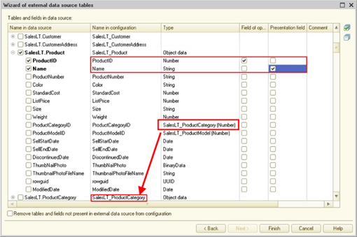
Fig. 488. External data source table wizard
While receiving the structure of an external data source, the system performs the following actions:
-
It attempts to determine whether object-based or non-object-based data is located in the table. The table will be considered object-based if only one key field is specified for it. It will be non-object-based otherwise. If the system made an error while specifying the key fields, you can manually modify the fields that form the table key. If the table is determined as object-based, you can specify its field that generates a presentation of this type of data. Specify the presentation manually.
-
It converts data source column types to 1C:Enterprise types that will be used to specify types of table attributes. All types from an external data source are converted into the following 1C:Enterprise types: number, string, date, boolean, UUID, binary data, and types related to object-based tables of data sources.
-
It attempts to determine types for table fields. In this case, the system tries to determine what type of data is stored in the table column. If it can be considered a reference to data in another table, the system specifies the relevant type in the column. If the system selected the incorrect table column type, you can change it manually.
-
When you set up load, you can set up the following parameters of the data structure to be loaded:
-
Name of the object in the configuration. The Name in the configuration column;
-
Type of the attribute to be loaded. The Type column;
-
Specify the fields included in the key (for object-based data). The Key field column;
-
Specify the field that stores the object presentation. The View presentation field.
-
Specify the field that stores the object version (for optimistic data locks). The Version field column.
-
Specify that the table or attribute is read-only. The Read only column.
-
Specify the option to specify the NULL value in the attribute. The NULL allowed column.
-
Specify the filling value for the attribute: the Filling value column.
-
Then select the checkboxes for the tables and fields to be moved to the application metadata.
If the Remove tables and fields not available in the external data source from the configuration checkbox is selected, the tables and fields absent in the external data source (for example, tables or fields have been deleted in the external source) will be deleted from the configuration once the table wizard stops operating.
Once you click Finish, the structure of the external data source will be loaded.
17.6.2.4. Sample for generating an external data source
For example, we have a dbf database that needs to be accessed from the application.
The database consists of three tables (files):
-
The products table (stored in the products.dbf file) that contains information about products and consists of the following fields:
-
id. Product ID (key field). Number.
-
code. Product code. Type: String.
-
name. Product name. Type: String.
-
article. Product SKU. Type: String.
-
-
The price table (stored in the price.dbffile) that contains the current prices of products and consists of the following fields:
-
product. ID of the product for which the price is stored. Number.
-
price. Product price. Number.
-
-
The sales table (stored in the sales.dbf file) that contains data about each sale of the product specifying the price, the quantity, and the amount. The table consists of the following fields:
-
product. ID of the product being sold. Number.
-
price. Retail price of the product. Number.
-
qty. Quantity of the sold product. Number.
-
summa. Retail price of the sold product. Number.
-
Let's generate the necessary configuration objects to have access to all the data of these tables.
First, generate the external data source. Name it DBF. Then manually generate tables of the data source. Keep in mind that the real name of the physical external data source table is specified in the Name in the data source property of the object to be generated. While generating the tables, name the configuration objects as follows:
-
The products table will be displayed into the Products object.
-
The price table will be displayed into the Prices object.
-
The sales table will be displayed into the Sales object.
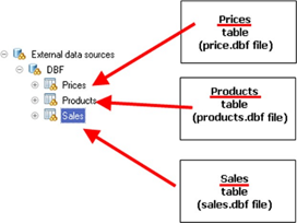
Fig. 489. External data source tables
Now generate fields for each table, specify field types, and assign fields of keys and presentations (if any).
The example will contain one object-based table (the Products table). Other tables will be non-object-based. You can see relations between fields of physical tables and fields of the configuration object as well as types of fields in fig. 490.
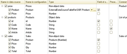
Fig. 490. Structure of tables in the application
Now specify the subsystem that includes the generated tables and other parameters of configuration objects (if necessary).
If then you start the system in 1C:Enterprise mode and correctly specify the parameters for connecting to the external data source, the navigation panel will contain the generated tables.
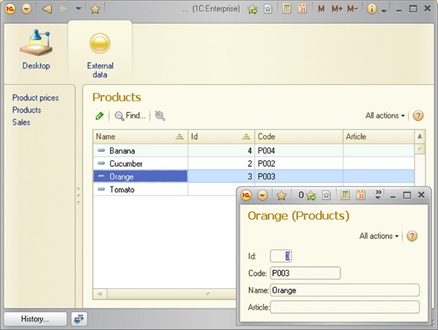
Fig. 491. Dynamic list of the external data source
17.6.2.5. ODBC connection string
17.6.2.5.1. General information
To connect to an external data source, generate a connection string that can contain either all connection parameters required for the selected ODBS driver, or an indication to the generated DSN (Data Source Name) data source description.
17.6.2.5.2. Full connection string
The connection string is described in English at: http://msdn.microsoft.com/en-us/library/ms722656.aspx. The following things should be noted in this description:
- The connection string parameters are written in Keyword=Value pairs and separated by the ";" character.
If there are multiple parameters with the same keyword in the connection string, the last indication of the parameter in the connection string will be used. Thus, if such parameters as Username or Password are specified both in the connection string and in the Connection parameters dialog box, the values from the Connection parameters dialog box will be used because these parameters will be added to the specified connection string from the right side.
To simplify the connection string generation, you can use the website: http://www.connectionstrings.com/.
17.6.2.5.3. Data source descriptions
Instead of specifying the full connection string, you can use extra utilities that can generate a data source description (DSN) and specify a construct of the DSN=NameDSN type in the connection parameters. Data source description can be user and system ones. User descriptions of data sources are available on this computer and only for the user who generated this description. The system description is generated by the system administrator and available to all users of this computer if they have required permissions.
17.6.2.5.4. ODBC data source administration utility
To generate a data source description, use the ODBC data source administration utility. To open this utility in Windows, go to Control Panel – Administration – Data Sources (ODBC). At this, the Windows Control Panel opens the administration utility corresponding to the version of the operating system. In Linux OS this utility is called ODBCConfig and available if the relevant package is installed (depending on the version of Linux OS).
Keep in mind that drivers and data sources are different for 32-bit and 64-bit ODBC in 64-bit Windows. Thus, to generate a data source description, use the administration utility relevant to the version of 1C:Enterprise system that will execute queries to an external data source. So, for example, if ODBC is accessed from the 64-bit version of 1C:Enterprise server, use the 64-bit version of the administration utility. If you use the 32-bit version of 1C:Enterprise on 64-bit Windows, use the 32-bit administration utility.
The administration utilities are located on 64-bit Windows as follows:
-
64-bit version: %SYSTEMROOT%/System32/odbcad32.exe.
-
32-bit version: %SYSTEMROOT%/SysWOW64/odbcad32.exe.
17.6.3. Operating external OLAP data sources
17.6.3.1. General information
OLAP is a data processing technology that prepares aggregated information based on big data arrays structured according to a multidimensional principle. Data in analytical databases (OLAP systems) is generated based on the data from transaction data processing systems (also called OLTP systems). Information in OLAP systems is represented as a space (called cube) whose axes are dimensions. Some measures are located in the nodes of this space. Each dimension of the cube is characterized by certain members of the dimension.
The closest (but not the exact!) analog of data storage in OLAP systems can be considered an accumulation register where the register itself is similar to a cube, a dimension of the CatalogRef type is similar to a cube dimension, the catalog itself contains dimension members, and register resources are similar to cube measures.
In the 1C:Enterprise system, an OLAP system cube is represented as a model, where:
-
A cube is represented as a cube in a configuration.
-
Dimensions and dimension members are represented as two objects:
-
Dimensions are analogs of dimensions.
-
Dimension tables are used to describe a collection of dimension members.
-
-
Measures are represented as resources.
Thus, the external source attached to the OLAP system contains cubes. Each cube consists of dimension tables, dimensions themselves, and resources. Dimension tables consist of fields. Cube resources can be numeric or string.
The object that describes an external data source can be used as follows:
-
As a data source for queries.
-
As a data source in the data composition system.
-
As a source for dynamic lists.
-
As a part of common attributes (see Common attributes).
-
Records of dimension tables and cubes can be displayed in managed forms of 1C:Enterprise (ordinary forms are not supported for objects of external data sources).
-
Dimension tables of an external data source can be used as types of infobase attributes.
-
Access rights can be applied to cubes, dimension tables, dimension table fields, dimensions, and resources of external data sources.
-
Access to cubes, dimension tables, dimension table fields, dimensions, and resourcesis possible from 1C:Enterprise language.
-
Cubes and dimension tables of an external data source can be part of subsystems (see Subsystems).
-
Cubes, dimension tables, and dimensions of an external data source can be part of functional options (see Functional options and functional option parameters).
-
You can generate characteristics for cubes of external data sources (see Charts of characteristic types).
To operate multidimensional external data sources, use XML for Analysis(XMLA). The platform gets access to data using HTTP requests to a web server, which can be external (in relation to the OLAP system) or built into the OLAP server. For issues of configuring access to OLAP server data, see the documentation for the system you are using.
The string of connection to an analytical external data source is a combination of the XMLA provider URL (for this OLAP system) and parameters used by 1C:Enterprise to operate the source. Data of external data sources is read-only.
The functionality of 1C:Enterprise is considered to the maximum when using the following OLAP systems as an external data source (the DBMS type property of the data source connection parameters):
-
IBM InfosphereWarehouse,
-
Microsoft SQL Server AnalysisServices,
-
OracleEssbase.
Note. Note. When you operate an external data source, errors may occur if theDBMS type property of the external data source connection parameters contains a value that does not correspond to the system actually used.
When you use other DBMS, options for operation of external data sources depend on the DBMS. To connect to an external data source, generate a connection string.
Specify a connection to an external data source not only in Designer (if you use the feature for table structure import from an external data source) but also in 1C:Enterprise mode to get the data.
Documents for OLAP systems:
-
IBM Infosphere Warehouse:
-
Microsoft SQL Server Analysis Services:
-
Version 2008: http://technet.microsoft.com/ru-ru/library/bb522607(v=sql.100).aspx (in Russian).
-
Version 2008 R2: http://technet.microsoft.com/ru-ru/library/bb522607(v=sql.105).aspx (in Russian).
-
Version 2012: http://technet.microsoft.com/ru-ru/library/bb522607(v=sql.110).aspx (in Russian).
-
-
Oracle Essbase:
17.6.3.2. General operation scheme
To use information from external data sources based on 1C:Enterprise, follow the following general scheme:
-
Study the structure of an external data source and figure out which information (cubes, dimension tables, dimensions, and resources) is required to operate algorithms or reports in 1C:Enterprise.
-
Generate the External data sources object in Designer and generate the required structure for it. For this, use a special assistant.
-
Implement the generated objects in the application.
-
Set up parameters for connection to the external data source in the network where the application will be used. These parameters may differ from those used when loading the structure of the external data source.
Note. Note. The parameters of access to the external data source that were set in Designer will not be used by the system in 1C:Enterprise mode.
17.6.3.3. Editing external data source structures
17.6.3.3.1. General information
To operate tables of external data sources, in the configuration tree, use the branch with the name of the relevant external data source: External data sources – <External data source name> – Cubes configuration tree. To determine an external data source:
-
Determine the external data source.
-
Determine cubes.
-
Determine dimension tables and fields for each dimension table.
-
Determine dimensions for the cube.
-
Determine resources for the cube.
The configuration can describe fewer objects than there are in the real database, but you cannot generate an object not included in the real database.
You can generate an external data source structure both in manual mode and when loading this structure using a special constructor.
17.6.3.3.2. External data source
When you create an external data source, specify its name. With this object, you can identify a group of cubes when accessing the data it contains. A data source consists of one or several cubes which, in turn, consist of other objects (dimension tables, dimensions, and resources).
17.6.3.3.3. External data source cubes
When you create a new cube, the object editing window opens (see Object editing window).
To identify the cube within the application, use the Name table property. For the system to know which physical cube of the external data source is related to the configuration object, fill in the Name in the data source property. The value in this property must exactly match the name of the cube in the external data source. Placing data from several cubes of an external data source in the same application cube is not supported.
17.6.3.3.4. Dimension tables
A dimension table describes members of an OLAP system cube dimension. The Name in the data source property contains the exact name of the dimension or the hierarchy level in the data source. The Presentation field property contains the name of the dimension or hierarchy level property that 1C:Enterprise uses to generate a presentation of a dimension table item.
If a dimension is hierarchical, a hierarchical dimension table can be used for such dimension. A hierarchical dimension table is described using the following properties:
-
Hierarchical. Indicates that the dimension table describes a hierarchy in the data source.
-
Hierarchy name in the data source. Specifies the name of the hierarchy to which the dimension table that describes the level.
-
Level number. If the table describes a hierarchy level, this property contains the number of this level. For a hierarchical table, the value of this property is 0, and the Hierarchy name in the data source property is the same as the value of the Name in the data source property.
With the Empty parent flag and Empty parent value properties, you can specify for 1C:Enterprise how to identify values of the highest hierarchy level.
17.6.3.3.5. Dimension table fields
Dimension table fields describe which dimension properties will be available from the application. The Name field property identifies a property (dimension table field) in the application. To specify the mapping between an application field and a dimension attribute, use the Name in the data source property. The value in this property must exactly match the dimension attribute name specified in the Name in the data source property of the parent object of this field. You cannot combine data from several attributes of one or several external data source dimensions in a single dimension table field.
The Type field allows you to specify the type of this field. A limited set of types is available for selection. Field types can be:
-
Number
-
String
-
Date
-
Boolean
-
UUID
-
BinaryData
-
Types defined by dimension tables of external data sources
If you need to specify a union type for a field, only the following types can be included in this union type: Number, String, Date, and Boolean.
When you receive data from external data sources, the system automatically converts this data to the type specified for the relevant field in the application. For conversion rules description, see Value conversion rules.
17.6.3.3.6. Dimensions
An external data source dimension describes an OLAP system cube dimension. The dimension type can only be a reference to the relevant dimension table. In fact, the dimension tables and dimensions themselves are one-to-one: one dimension is described by one-dimension table.
You cannot combine data from several dimensions of an external data source in a single dimension field.
17.6.3.3.7. Resources
An external data source resource describes an OLAP system cube fact. A cube resource can be numeric or string. Values of resources are calculated using values of cube dimensions. The Name in the data source property must match the fact (resource) name of the external data source cube.
You cannot combine data from several (facts) resources of an external data source in a single resource.
17.6.3.3.8. Loading the table structure from external data cubes
You can load the cube structure from an external data source available for the developer (for example, copies of a real database).
To do this, when you create a cube, specify Select from external data source cube list in the external data source cube wizard. Then specify the external database connection string using the Connect to data source window. While generating the connection string, you can use the wizard of the string for connection to an external data source. For this, click "..." to the right of the Connection string field.
After the connection to the external database is successfully completed, a list with cubes, dimension tables, dimension table fields, and resources of the attached data source will be opened. Then select the required cube, dimension tables, fields, and resources that will be used by Designer to generate a structure of objects that describe the current data source.
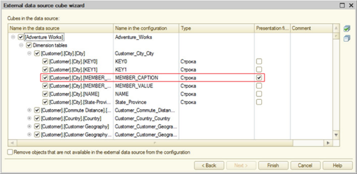
Fig. 492. External data source table wizard
While receiving the structure of an external data source, the system performs the following actions:
-
It attempts to determine fields that generate presentations for dimension tables. If the system has made a mistake, you can specify the presentation field manually.
-
It converts data source column types to 1C:Enterprise types that will be used to specify types of object attributes. All types from an external data source are converted into the following 1C:Enterprise types: number, string, date, boolean, UUID, binary data, and types related to data source dimension tables.
-
It attempts to determine types for dimension table fields. In this case, the system tries to determine what type of data is stored in the dimension table column. If it can be considered a reference to data in another dimension table, the system specifies the relevant type in the column. If the system selected the incorrect table column type, you can change it manually.
Then select the checkboxes for the objects to be moved to the application metadata.
If the Remove objects that are not available in the external data source from the configuration checkbox is selected, the objects (cubes, dimension tables, dimensions table fields, and dimensions) absent in the external data source (for example, the cube or resource has been deleted from the external source) will be deleted from the configuration once the cube wizard stops operating.
Once you click Finish, the structure of the external data source will be loaded.
17.6.3.4. Query language limitations when using analytical external data sources
sourcesWhen you operate cubes and dimension tables in the query language, consider the following limitations:
| Expression | Microsoft SQL Server Analysis Services | Oracle Essbase | IBM Infosphere Warehouse |
|---|---|---|---|
| ALLOWED | – | – | – |
| DISTINCT | – | – | – |
| GROUP | – | – | – |
| HAVING | – | – | – |
| JOIN | – | – | – |
| UNION | – | – | – |
| Subqueries | – | – | – |
| FOR UPDATE | – | – | – |
| EMPTYTABLE | – | – | – |
| YEAR | Yes | – | – |
| QUARTER | Yes | – | – |
| MONTH | Yes | – | – |
| DAYOFYEAR | Yes | – | – |
| DAY | Yes | – | – |
| WEEK | Yes | – | – |
| WEEKDAY | Yes | – | – |
| HOUR | Yes | – | – |
| MINUTE | Yes | – | – |
| SECOND | Yes | – | – |
| BEGINOFPERIOD | Yes | – | – |
| ENDOFPERIOD | Yes | – | – |
| DATEADD | Yes | – | – |
| DATEDIFF | Yes | – | – |
Where:
-
–. The specified expression is not supported during operation of the relevant OLAP system.
-
Yes. The specified expression is supported during operation of the relevant OLAP system.
17.6.3.5. OLAP server connection string
The OLAP server connection string looks as follows:
http://:/?Where:
-
OLAP host address, port, source. Address of access to the OLAP system generated according to the rules described in the documents for a certain OLAP system.
-
parameters. Parameters used by 1C:Enterprise to access OLAP system data. Parameters are set in the Parameters=Value form. Parameters are separated by &. The following parameters are used:
-
ProviderName. Name of the XMLA service in the OLAP source.
-
DataSourceName. Name of the OLAP source.
-
Catalog. Name of the directory or the database in the OLAP source.
-
Examples of connection strings are given below:
For Microsoft SQL Server Analysis Services:
http://localhost:80/msolap/msmdpump.dll?ProviderName=Microsoft
Analysis Services& DataSourceName=host&Catalog=Adventure Works DWFor Oracle Essbase:
http://localhost:13080/aps/XMLA?ProviderName=Essbase
XML for Analysis&DataSourceName=host&Catalog=Sample17.6.4. Procedures and functions of external data sources
17.6.4.1. General information
The query language (see Working with queries) and the data composition system (see Data composition system) provide great data processing features but do not include specific options of different DBMS, which include functions, sequences, stored procedures, and different specific DBMS constructs. At the same time, certain DBMS tools might be critical for operations with external data sources. An example is an object-based DBMS table whose key is retrieved from a sequence. Functions and procedures can return nothing (a procedure), as well as return a single value or table.
To operate such DBMS objects, 1C:Enterprise has the concept of an external data source function. Functions in 1C:Enterprise can be of the following types:
-
A table of the expression type in a relational data source.
-
A function that does not return values (a procedure).
-
A function that returns a value.
Any of the above functions can take parameters. The number of parameters can be either fixed or variable. An external data source function can be both a layer between the real function (or the stored procedure) of the DBMS and explicitly describe some construct that will be placed into the query being executed.
Functions can be used in the 1C:Enterprise language, the query language, and the data composition system. For functions, you can specify access rights that regulate the use of these functions.
17.6.4.2. General operation scheme
To use functions from external data sources based on 1C:Enterprise, follow the following general scheme:
-
Study the structure of an external data source and figure out which functions, procedures, or constructs in the DBMS language are needed to operate algorithms or reports in 1C:Enterprise.
-
Generate the External data sources object in Designer and generate subordinate functions for it. For this, use a special assistant.
-
Implement the generated objects in the application.
-
Set up parameters for connection to the external data source in the network where the application will be used. These parameters may differ from those used when loading the structure of the external data source.
Note. Note. The parameters of access to the external data source that were set in Designer will not be used by the system in 1C:Enterprise mode.
17.6.4.3. Editing functions
17.6.4.3.1. General information
To operate functions of external data sources, in the configuration tree, use the branch with the name of the relevant external data source: External data sources – <External data source name> – Functions. To determine an external data source:
-
Determine the external data source.
-
Determine data source functions.
-
If procedures that return tables exist in the external data source, also determine tables of the external data source belonging to the expression type.
The configuration can describe fewer functions and procedures than there are in the real database. You can also describe a function (in the language of the used DBMS) that is absent in the real database. At this, remember the following features:
-
If it is specified for a function (as a configuration object) that an expression returns a value, then:
-
When used in 1C:Enterprise language, the expression is placed in the select<expression> construct.
-
When used in the query language or the data composition system, the function call is replaced with the expression itself.
-
-
If it is specified for a function (as a configuration object) that it does not return a value, then:
-
When used in 1C:Enterprise language, depending on the DBMS, either a call using the select <expression> construct, or the ODBC call escape sequence will be used. Because of this, it is not recommended that you use an arbitrary expression for a function that does not return a value to achieve the maximum compatibility with various DBMS.
-
When used in the query language or the data composition system, it is not supported.
-
You can generate an external data source structure both in manual mode and when loading this structure using a special constructor.
17.6.4.3.2. External data source
When you create an external data source, specify its name. This object is used to identify functions when called. The data source consists of one or several functions. It is also possible that expression tables are located in the external data source.
If an external data source object is used only to call procedures and functions, the value of the Data lock management mode property is meaningless. If the lock management mode is set to Automatic and managed for an external data source, the lock mode for each table is determined by the value of the relevant table property. If a certain lock management mode is selected for an external data source, the property of the external data source table with the same name is ignored.
17.6.4.3.3. External data source functions
When you create a function, the window of the external data source function wizard opens. If the manual generation mode is selected, the property palette of the generated external data source function will open (see Property palette).
The property of the Name function is used to identify the function when it is called. The Expression in the data source property will contain the expression that will be used in the real query in the database when the function is used. In this property, you can specify not only a call to a real function or a stored procedure of the database, but also write an expression in the DBMS language of the external data source.
The Returns value property actually indicates what is described in the configuration object:
-
True. Function or expression that returns a value. In this case, also specify what type of value will be returned by this expression.
-
False. Procedure or expression that does not return a value.
A procedure or function can take parameters. For more information about parameters, see page Parameters of external data source functions.
A function can be an expression in the DBMS language, for example, a function that receives the next sequence value (SimpleSequence) will look as follows:
NEXT VALUE FOR
dbo.SimpleSequenceIf you need to get the next sequence value from 1C:Enterprise language, it will look as follows:
KeyValue = ExternalDataSources.ExternalData.NextKeyValue();In this example, ExternalData is the name of the external data source that describes the NextKeyValue() function. The NextKeyValue() function is described above.
The function also can be written in the language of the used DBMS. At this, it is recommended that you enclose the expression in parentheses to avoid various side effects during execution of a real query. Keep in mind that when transforming a query from the query language of the 1C:Enterprise platform into the SQL dialect of a certain DBMS, functions are placed directly in the text of the resulting query (function parameters are placed automatically).
17.6.4.3.4. External data source tables of the expression type
Functions can return not only values but also tables. In this case, the function must be generated as a table of the expression type. For actions necessary to create an external data source table, see External data source tables. You also need to describe the fields of the returned data in the same manner as the standard fields of the external data source table (see External data source table fields).
17.6.4.3.5. Loading functions from external data sources
You can load the table structure from an external data source available for the developer (for example, copies of a real database).
To do this, when you create a table, specify Select from list of external data source functions in the external data source function wizard. Then specify the external database connection string using the Connect to data source window. While generating the connection string, you can use the wizard of the string for connection to an external data source. For this, click "..." to the right of the Connection string field.
After the connection to the external database is successfully completed, a list with procedures, functions, and sequences of the attached data source will be opened. Then select the objects that will be used by Designer to generate a structure of objects that describe the current data source.
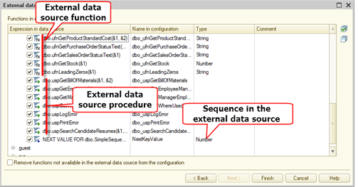
Fig. 493. External data source function wizard
You can specify the name under which the function will be generated in the 1C:Enterprise configuration.
If the Remove functions not available in the external data source from the configuration checkbox is selected, the functions absent in the external data source (for example, functions have been deleted in the external source) will be deleted from the configuration once the function wizard stops operating.
Once you click Finish, the structure of the external data source functions will be loaded.
17.6.4.3.6. Parameters of external data source functions
Formal parameters of external data source functions are described as &n, where n is the parameter number. Parameter numbering starts from 1. If parameters are optional, they are enclosed in curly brackets ({}). Optional parameters are determined each time the procedure or function is actually called. NULL (for each optional parameter) replaces actual parameters absent in the optional block after the call.
//function with two
parameters
dbo.uspGetWhereUsedProductID(&1, &2)
//function with two
optional parameters
dbo.uspGetWhereUsedProductID(&1{, &2, &3})If a procedure or function can take a variable number of parameters, this construct is described as &n[]. In this case, actual parameters will be placed in the expression instead of the &n[]construct separated by commas. An indication of the option to pass a variable number of parameters can only be the last one in the list of formal parameters.
//function where the
number of passed parameters can vary from 2 to the number
// limited by the used
DBMS
dbo.uspGetWhereUsedProductID(&1, &2[])17.6.5. Manage external data sources
Before you start using data from external sources in the application, set up the connection parameters for the used external sources. To do it, use the standard Management of external data sources function. It is called from the Advanced tools – Standard functions window.
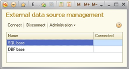
Fig. 494. Manage external data sources
This form lists all external data sources generated in Designer and available for the user who has opened the form.
The Attached column indicates the status of the connection to the data source in this session.
Using the Administration menu, you can specify the general connection parameters (the Change common parameters... command) and connection parameters for certain users if these parameters are different from the general parameters (the Change user parameters... command).
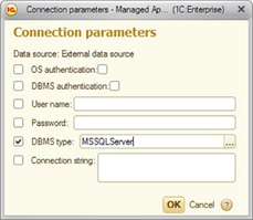
Fig. 495. Connection parameters
The checkbox in the left part of the form (before the parameter names) means that this parameter is used in this set of connection parameters. At this, parameters are analyzed as follows:
-
Parameters set for the session using the SetSessionConnectionParameters() method of the external data source manager.
-
Parameters set for the user during interactive setup or using the SetUserConnectionParameters() method of the external data source manager.
-
General parameters set interactively or by calling the SetCommonConnectionParameters() method of the external data source manager.
The resulting set of parameters will be used to connect to the external data source. If a parameter is specified in several settings, the value of the parameter that will be found earlier in the above chain will be used.
For example, you can combine connection parameters as follows:
-
In the session connection parameters, specify the user and their password.
-
In the general parameters, specify the string for connection with the database of the external source.
-
In the user-specific parameter, specify another connection string that can be used to test the application.
When you specify the connection string, keep in mind that external data will be accessed not from the computer used for the setup, but from another computer (the description from which computer the query for the external data source will be sent).
When you click Connect, the dialog box opens. Here you can set up or specify parameters for connection to the selected external data source.
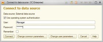
Fig. 496. Connection parameters
The ODBC driver and the connection string determine the need to specify a user and password in this dialog box. There may be situations when a username and password is not required. If the user is not an administrator of the external data source, the General parameters... and User parameters... buttons are not available for the user.
The Use operating system authentication checkbox is available only if the user has the SessionOSAuthenticationChange right.
After you click Connect, a connection to the external data source is made. If the connection is successful, the components of the Connected column in the list of external data sources are changed.
When you click Disconnect, 1C:Enterprise will be disconnected from the selected external data source.
17.6.6. Connecting to external data sources in 1C:Enterprise mode
Any operation that requires data to be received from an external data source will attempt to establish connection if the connection to this data source has not been made yet. If the connection is successful, the actions will continue. If the connection fails, an exception is thrown.
If an exception related to connection to an external data source is thrown in the client application, the user is prompted with the dialog box where they can specify connection parameters (if the user has rights to modify parameters) and retry the connection. If the connection is successful, the user will be prompted to repeat the action during which the connection error occurred.
Note. Note. In version 8.2.13 compatibility mode, during operation of a dynamic list, the dialog box for connection to external data may not be displayed in some cases.
You can also connect manually. For this, use the standard Management of external data sources function.
17.6.7. External data source features
17.6.7.1. Place for executing queries to external data sources
Queries to external data sources are executed:
-
In file mode. On the computer with the client application.
-
In file mode with access via the web server. On the computer where the web server extension is running.
-
In client/server mode. On the computer where it runs:
-
Service for operation of external data sources via ODBC. For access to relational data sources.
-
Service for operation of external data sources via XMLA. For access to analytical data sources (OLAP systems).
-
17.6.7.2. Using external data sources
If one external data source contains both data from relational data sources and data from analytical data sources, they cannot be used simultaneously. It happens because one external data source can be connected to either a relational DBMS or an analytical DBMS at one time.
17.6.7.2.1. In queries
To relational external sources
External data source tables can be used as query sources. At this, the table of the external data source is described as follows:
ExternalDataSource..Table.<Table
name>Example:
SELECT
Goods.Code, Goods.Description, Goods.SKU
FROM
ExternalDataSource.DBF.Table.Products AS GoodsIn this example, the Code, Name, and Article fields are selected from the Products table of the external DBF data source.
Temporary tables can be used in a query to an external data source. At this, the attempt to generate the temporary table directly in the database related to the external data source occurs. If DBMS does not support generation of temporary tables, an exception will be thrown. The name for the temporary table, during its calling, is generated as follows:
ExternalDataSource.<Name of the
external data source>.TemporaryTable.<Name of the temporary table>Example:
SELECT Name, ProductID
INTO
ExternalDataSource.AdventureWorks.TemporaryTable.Rest
FROM &ValueTable
SELECT Name, ProductID
INTO
ExternalDataSource.AdventureWorks.TemporaryTable.Rest
FROM
ExternalDataSource.AdventureWorks.Table.Production_BalanceWhen you use external data sources in queries, keep the following limitations in mind:
- One data source can be used in one query. For example, an external data source and 1C:Enterprise infobase data cannot be used simultaneously.
To analytical external sources
Objects of analytical external data sources may be used as sources of queries. At this, the cube of the external data source is described as follows:
ExternalDataSource..Cube.Example:
SELECT FIRST 10
AdventureWorks.InternetSalesAmount
FROM
ExternalDataSource.OLAP.Cube.AdventureWorks
AS AdventureWorksIn this example, first 10 resources of InternetSalesAmount are acquired from the cube AdventureWorks of the external data source OLAP.
Note. Important. It is not recommended that you get all entries from the cube of the external data source. The amount of entries is very large and may cause overrun of the system.
The dimension table for the cube of the external data source is described as follows:
ExternalDataSource.<Name of the
source>.Cube.<Name of the cube>.DimensionTable.<Name of the
dimension table>Example:
SELECT
AdventureWorks
DimensionTableProduct.Link
FROM
ExternalDataSource.OLAP.Cube.AdventureWorks.DimensionTable.Product
AS AdventureWorksDimensionTableProductIn this example, the list of links to members of the dimension table Product is acquired from the cube AdventureWorks of the external data source OLAP.
Temporary tables can be used in a query to an external data source. At this, the attempt to generate the temporary table directly in the database related to the external data source occurs. If DBMS does not support generation of temporary tables, an exception will be thrown. The name for the temporary table, during its calling, is generated as follows:
ExternalDataSource.<Name of the
external data source>.TemporaryTable.<Name of the temporary table>When you use external data sources in queries, keep the following limitations in mind:
- One data source can be used in one query. For example, an external data source and 1C:Enterprise infobase data cannot be used simultaneously.
17.6.7.2.2. In the data composition system
In the data composition system, you can use data sets that receive data from various uniform data sources. Thus,you can generate a data set that describes a list of products. The data in this set will be acquired from the 1C:Enterprise infobase. Another data set can describe data acquired from an external data source, for example, a table of product sales from an external database.
Then you can set up data set links in the data composition schema wizard and get the information in the report from both 1C:Enterprise and the external data source.
17.6.7.3. Value conversion rules
When you receive data from external data sources, the system automatically converts this data to the type specified for the relevant field in the application. The conversion is performed according to the following rules:
-
String:
-
The string value is converted to a string value.
-
The numeric value is converted to a string value (the regional settings of the operating system on the computer where the query to the external data source is executed are used for conversion).
-
The date value is converted to a string value (the regional settings of the operating system on the computer where the query to the external data source is executed are used for conversion).
-
The UUID value is converted to a string presentation of the UUID.
-
Binary data (and data of other types) is converted to a string, which is the text presentation of the data being converted in hexadecimal.
-
-
Number:
-
The numeric value is converted to a number.
-
For a string value, an attempt is made to convert the string to a number according to the regional settings of the operating system on the computer where the query to the external data source is running.
-
For fields whose accuracy in the source base exceeds the accuracy of platform types, it is recommended that you either explicitly use CAST in queries or generate a presentation in the base so that the accuracy of the fields matches the accuracy in Designer.
-
An exception is thrown for other types.
-
-
Boolean:
-
The numeric value is converted to False if it is equal to 0. It is converted to True for any other value in the external source.
-
Binary data is converted according to the value of the first data byte. If the first byte is 0, the result of the conversion is False and True in case of any other value.
-
An exception is thrown for other types.
-
-
BinaryData:
- All types of values are converted into binary data.
-
Date:
-
The date value is converted to a Date value.
-
An exception is thrown for other types.
-
17.6.7.4. External data source included in separators
If an external data source is part of a common attribute, keep the following features in mind:
-
The structure of external data source tables is not changed, so the actual data is not separated.
-
Parameters for connection to an external data source are stored broken down by values of separators containing the external data source.
-
The unused separator is an individual value broken down by which parameters for connection to an external data source are stored.
Thus, when you include the external data source in the separator, you will get the option to implement one of the following usage scenarios:
-
Data available to users of various data areas is located in different databases that match in the table structure. Since the connection parameters are stored broken down by separator values, you can configure the required database for each data area.
-
Data available to users of various areas is located in the same database, but access to the data is managed by the DBMS (username and password). In this case, for each data area, you can specify its own name and password of the user on whose behalf the data is accessed.
The given scenarios are not the only ones. They are given as an example of external data sources included in separators.
17.7. Reusing Internet service sessions
17.7.1. General information
The structure of 1C:Enterprise is such that calling an internet service (web service, HTTP service, standard OData service) and client application startup is almost the same: the system creates a session with the infobase, where all the required actions are performed. Upon completing the internet service call (when the client application terminates) the session is finished, and after the repeated call the process is repeated again. The evident disadvantage of such a behaviour is a considerable period of time spent on creating a session (including execution of all event handlers and load of the configuration itself). Particularly it can be noted with "big" applications that contain many different configuration objects. For a client application, the session creation time may be insignificant (compared to the total time of continuous operation of the client application). For Internet services, this time may introduce significant delays into the total time of the service call. Within the application, you can manage the need to create a session each time an Internet service is called:
-
Do not apply session reuse. A new session will be created each time the Internet service is accessed.
-
Enable session reuse. In this case, creation and termination of session is controlled by the caller using HTTP request headers.
-
Enable automatic session reuse. In this case, a session pool is organized. Each session of the pool is characterized by a set of parameters. If a pool session is free and has the same set of parameters as the Internet service request, an existing session will be provided to the request at once.
The option to reuse sessions is configured in several places:
-
In the properties of the web service and HTTP service configuration objects (type of session reuse and lifetime).
-
In the default.vrd publication file (session pool parameters).
Keep in mind that the values in the default.vrd file take precedence over the values specified in the properties of configuration objects.
17.7.2. Types of session reuse
Do not use
In each case, each request for an Internet service will result in creating a new session.Use
In this case, the Internet service client directly controls the lifetime and nature of the session reuse. To control the creation of a new session, Use special HTTP request headers for the Internet service.Use automatically
A session pool should be broken down by the following parameters:-
Service type
-
Service name
-
User
-
Password
-
Separator set
-
Safe mode
Upon detecting an incoming request to an Internet service, the current session pool is analyzed, and a session with parameters is searched for, which request matches the incoming request. If such session is detected and it is not used by a request from another Internet service client, the incoming request will be served by the found session. If no free session is detected, an attempt to create a new session is executed. If the session pool size is exceeded when trying to create a new session, the incoming query will be expecting for some time (pool timeout). If no free session is found after the pool timeout, the Internet request will be terminated with a 406 Not Acceptable error. The free session will be destroyed automatically after the free session lifetime expires.
Automatic session pool settings are valid within the publication. Thus, if several publications are created for an infobase, then the pool setting of the publication through which the call is made is used for calling the Internet service.
We recommend that you size your session pool so that there are a few free sessions in the pool at maximum load. That is, choose a pool size with a small margin. Otherwise, some calls will be performed with errors at the maximum load. 1C:Enterprise does not support automated determination of the necessary session pool size.
17.7.3. Session reuse settings
17.7.3.1. Internet service properties
The property palette of Internet services (web service, HTTP service), including the native Internet services of configuration extensions, has two properties that describe session reuse:
-
Session reuse. Specifies the type of session reuse for the custom service (see Types of session reuse).
-
Session lifetime:
-
Specifies how long a "free" session will be deleted from the session pool in case of automatic session reuse.
-
Specifies how long the idle session will be forced terminated by the system when manually reusing sessions.
-
If this property is set to 0, it means that sessions are not reused. This setting is equivalent to setting the Session reuse property to Do not use.
To configure the session pool parameters for automatic session reuse, use the default.vrd file.
17.7.3.2. On the client
If the Session reuse property for an Internet service is set to Use, then the session lifetime is managed by the Internet service client. The IBSession HTTP request header is the control. This header can take two values:
- start. In this case, 1C:Enterprise creates a new session, performs authentication, and sets separators, and all required event handlers are executed. If a new session cannot be created, the client will receive a 406 Not Acceptable error. If the session has been successfully created, the HTTP response contains a directive to set an ibsession cookie with the created session ID: Set-Cookie: ibsession=<Session ID>.
If you need to use an earlier created session, specify the ID of the earlier created session in the HTTP request to 1C:Enterprise: Cookie: ibsession=<Session ID>. If the request contains a session ID that was not created earlier or has been finished, the client receives a 400 Bad Request error.
If the HTTP request does not contain the IBSession header, the session is created and terminated each time the Internet service is called.
If the session safe mode or separator values are changed when using the session in the HTTP request, then the new parameters are ignored, and the session will use the values that were specified when the session was started.
- finish. In this case, 1C:Enterprise terminates the session specified in the request, along with the session termination command: Cookie: ibsession=<Session ID>. The session will be terminated automatically if no actions are executed in this session during its lifetime.
The session pool is not used in this case.
17.7.3.3. For the standard OData interface
The session reuse mode and parameters for the standard OData interface are set by 1C:Enterprise while publishing the standard OData interface on the web server. The following default values are used:
-
Session reuse. Automatic use is enabled.
-
Session lifetime. 20 seconds.
17.8. Integration services
17.8.1. General information
To interact with Enterprise Service Bus systems in 1C:Enterprise, use the integration service feature. We will use the following terms to describe it:
-
External integration service. 1C:Bus software product to which 1C:Enterprise connects. 1C:Bus interacts with various message exchange systems. The Integration service object is an adapter for the external integration service in the 1C:Enterprise object model.
-
Channel. Logical address in the message exchange system. Use the channel to transfer messages of a certain type. Channels can be of the following types:
-
Receiving. Used to receive messages from an external integration service.
-
Sending. Used to send messages to an external integration service.
-
Channels cannot be bidirectional.
-
-
Message. Atomic exchange element. The message includes the message data (in any supported format) and the message header used by an external integration service. The message has a certain lifetime used by an external integration service during message delivery.
Operations with messages have the following features:
-
The sender adds messages to the channel in sequence.
-
The recipient gets the messages from the channel in sequence. The sequence of sending messages and the sequence of receiving messages are the same.
-
Messages from different channels are delivered and processed in parallel.
-
If two messages are received from different channels in a certain sequence, they may be processed in a different sequence since the message processing speed may not be the same in different channels.
The 1C:Enterprise integration service feature is not an alternative to the exchange plan feature, since it can only transport messages and cannot generate outgoing messages and process incoming messages. However, the exchange plan feature can be a data source for messages sent using the integration service.
Interaction with an external integration service guarantees the message delivery, which means that:
-
Each sent message is stored in the infobase until an external integration service confirms that the message was received.
-
1C:Enterprise will continuously attempt to send a message to an external integration service until the external integration service confirms that the message was received, or until the message expires.
-
When the infobase receives a message from an external integration service, it stores the message and then sends a confirmation to the external integration service that the message was received.
17.8.2. Editing integration services
Integration services are located in the General branch of the configuration metadata tree. You can create and edit objects in a standard way. Use the External integration service address object property to specify the address of the external integration service used. After you specify the address of the external integration service, specify service integration channels to be used from 1C:Enterprise. You can do it the following ways:
- Specify channels manually. For this, use the Channels tab of the service integration edit window. When you create a channel, specify the following:
-
Name. Channel ID in 1C:Enterprise.
-
Name of the channel of external integration service. Channel ID in the external integration service. This ID is used to match the 1C:Enterprise object and the object in the external integration service.
-
Message direction. Indicates that the channel is used to send or receive messages. If the channel is used to receive messages, you can specify a handler to process incoming messages (the Message receive handler property). This handler will be stored in the integration service module. This module is executed on the 1C:Enterprise server.
-
In transaction. Indicates that the received message handler will be executed within the transaction. The message processing procedure depends on whether this checkbox is selected or cleared:
- The checkbox is selected. A transaction begins before calling the message receive handler. Then the handler is called.
If the handler refuses to process the message (the Cancel parameter is set to True or an exception is thrown in the handler), the transaction is canceled. The next message is not processed until the current message is successfully processed.
If the handler completes successfully, the message is marked as processed, and the transaction is committed.
- The checkbox is cleared. A transaction does not start before calling the message receive handler.If the handler refuses to process the message (the Cancel parameter is set to True or an exception is thrown in the handler), the next message is not processed until the current message is successfully processed.
If the handler completes successfully, the message is marked as processed.
Note that if an error occurs while setting the processed mark for a message, the system calls the message receive handler again after the system is restored, although the handler was previously executed successfully. In other words, if transactions are disabled for an integration service channel, the message receive handler must be written based on the assumption that the same message can be received more than once.
- Select the channels to be used in 1C:Enterprise from the list of available channels of the specified external integration service. To do this, use the Importing external integration service channels dialog box. To open it, click Import channels in the integration service context menu. This dialog box displays all available channels of the selected external integration service.
17.8.3. Using integration services
To use an external integration service:
- Prerequisites:
-
Find out the address of one or more external integration services you plan to use. You can specify addresses of external integration services upon application deployment.
-
Find out the names of the channel in each integration service you plan to use in 1C:Enterprise.
- While developing:
-
Create the required number of the Integration service objects in the configuration. A single object matches a single external integration service.
-
Create a list of channels to be used by the configuration for each created integration service. Specify the appropriate channel names and directions.
-
For each sending channel, implement a program code that will send messages to the specific channel of the required external integration service. Thus, the application will be able to send data to ESB.
-
For each receiving channel, implement a handler that will process all incoming events from the specific channel of the required external integration service. Thus, the application will be able to receive data from ESB. When you develop a message receive handler, take into account the In transaction checkbox behavior (see Editing integration services).
-
To debug the created API, the application developer must have access to the deployed test external integration service. The test external integration service must provide the same features as the real ESB.
- While deploying:
-
Specify the addresses of the external integration services using the standard function of integration service management.
-
Specify whether integration services are used using the standard function of integration service management (if necessary).
17.8.4. Using integration services
To send a message, create an object of the IntegrationServiceMessage type. To do this, use the CreateMessage() manager method of the corresponding integration service. An object of the IntegrationServiceMessage type is used both when sending and receiving messages. In this regard, some properties of this object are read-only, and new values can be assigned to some properties. Let's take a closer look at the object properties:
-
SendDate. Set when you send a message. Cannot be edited programmatically.
-
ExpirationDate. Use this property to get the point in time after which the message is considered expired and should not be processed. A message is considered expired if the message ExpirationDate is less than the current universal date of the computer that is processing the messages. You can set the property value only when the message is created by the CreateMessage() method. You cannot change this value later.
Expired messages are deleted from the queue when executing background jobs for sending and receiving messages.
Stored in UTC format. When you set/get the value, it is converted based on the time zone of the current session.
-
ID. UUID used to uniquely identify a message. This ID can be used when generating request-response chains. In this case, set the incoming message ID as the value of the CorrelationId property.
-
CorrelationId. UUID that allows the receiving party to determine which message this message responds to. You can only change it for a message that was not sent to the channel.
-
SenderCode and RecipientCode. String IDs that allow you to identify the message sender and recipient. IDs correspond to the codes from the catalog of integration participants of the selected integration service. If necessary, you can specify multiple message recipients at the same time. To do this, in the RecipientCode property, enter a string where the recipient codes are separated by ",". You can only change property values for a message that was not sent to the channel.
-
Parameters. Use this property to set a specific set of parameters for a new message. The set will be used by the recipient to process the message. The parameter name and its value are string type values.
-
BodySize. Shows a message body size. Until the message is sent, the property shows the amount of data written to the message. After the message is sent, the property shows the amount of data sent to the bus.
To add any data to the message or get any data from the message, use the GetBodyAsStream() method. This method returns the Stream type value (for more information, see Binary data operations). When you send a message to this stream, you can write arbitrary data that will be passed in the message. When you read a message from this stream, you can read the message data. You can write data only to a stream that is received for a created but not sent message. Sent and received messages are read-only. You cannot change the position in the stream in any case.
Once the message is generated, send it to the recipient. To do this, use the SendMessage() method of the integration service channel manager. To call the method, use the channel of the integration service for which the message was created. You cannot create a message for one integration service and send it to a channel of another integration service. The message gets into the message queue located in the 1C:Enterprise database.
To check the integration service channel state, use the GetState() method. The state is the status of the channel connection to the external integration service.
To manage the message queue, use the ExecuteProcessing() and StopProcessing() methods of the integration service manager. Use the ExecuteProcessing() method to run system background jobs that send and receive messages from external integration services. To stop message operations, you can stop the scheduled job execution or call the StopProcessing() method of the integration service manager.
As mentioned earlier (see General information), messages are stored in a queue located in the infobase until:
-
Messages are received by the external integration service (for sending channels).
-
Messages are processed by the infobase (for receiving channels).
You can receive and delete messages that are in the queue of any integration service channel. In other words, you can receive and delete only outgoing messages that have not yet been sent to external integration services, or incoming messages that have not yet been processed by 1C:Enterprise loading mechanisms. To get a list of messages in the queue, use the SelectMessages() method of the integration service channel manager. When you receive a list of messages, you can set filter criteria that will limit the list of messages to receive, as well as the total number of messages to receive. To set the filter, create a structure that will be passed as a Filter method parameter. The MaximumCount parameter specifies the total number of messages that match the specified filter you need to receive. If you specify parameters in the message using the Parameters message property, to filter messages by these parameter values, set as follows:
MessagesFilter = New Structure;
ParametersFilter = New Map;
ParametersFilter.Insert("Parameter1", "Value1");
ParametersFilter.Insert("Parameter2", "Value2");
MessagesFilter.Insert("Parameters", "ParametersFilter");
arrayResult = IntegrationServices.DataBus.UrgentMessages.SelectMessages(MessagesFilter, 10);In this example:
-
DataBus. Integration service created in the application.
-
UrgentMessages. Channel of the integration service whose messages you need to receive.
In this example, an array containing no more than 10 messages will be received. Each message will contain the following parameters:
-
Parameter1 set to Value1.
-
Parameter2 set to Value2.
To delete multiple messages, use the DeleteMessages() method. Deleting a message for a sending channel means that this message will not be received by the external integration service. Deleting a message for a receiving channel means that this message will not be processed by the application. There are several ways to determine the list of messages to delete using the method parameter:
-
If the parameter is set to Undefined, all messages are deleted from the channel queue.
-
Array of message IDs. The specified messages are deleted. The message ID is located in the IntegrationServiceMessage.ID property.
-
Structure describing how to filter messages. The filter of messages to delete is similar to the SelectMessages() method filter. All channel messages that meet the specified filter criteria are deleted.
17.8.5. Settings and activity
Each integration service has settings that can be specified either from 1C:Enterprise language or using the standard Management of integration services data processor. For more information about the standard data processor, see its help. Read this section to learn about how to change the integration service settings using 1C:Enterprise language.
You can get and specify the registration service settings using the following methods of the integration service manager: GetSettings() and SetSettings(). In each case, the IntegrationServiceSettings object is used. Let's take a closer look at the object properties:
-
ExternalIntegrationServiceAddress. Use this property to specify the external integration service address.
-
ExternalIntegrationServiceUserName and ExternalIntegrationServiceUserPassword. Use these properties to specify credentials for 1C:Enterprise platform to connect to an external integration service. In other words, these are the credentials of the external integration service user. Set them if the external integration service has an authorization tool.
-
UserName. Use this property to specify the 1C:Enterprise user on whose behalf the system background job for processing received messages will be executed. The specified user determines the access rights. If the user is not specified, the user choice depends on 1C:Enterprise mode, and the DefaultRoles configuration property determines the access rights. If this property is not filled, access rights are not controlled.
17.8.6. Organizing integration services
17.8.6.1. Receiving messages
17.8.6.1.1. General information
In general, messages are received from an external integration service and processed as follows:
-
When executing the ExecuteProcessing()method of the integration service manager, the platform creates a network connection with an external integration service. This connection is held for 2 minutes. Every time the ExecuteProcessing() method is called, the timeout starts from the moment the method is called. If there is no method call within 2 minutes, the network connection is closed and the interaction with the external integration service is interrupted. This behavior does not depend on the infobase mode (file or client/server) used for the integration service operations. In this regard, we recommend that you call the ExecuteProcessing() method using a scheduled job that must run once a minute.
-
Several background jobs process messages received from an external integration service. Their behavior depends on whether you use file or client/server infobase mode. For more information, read below in this chapter. To learn more about file mode, read below in this chapter.
-
Once the external integration service notifies the platform of a new message, the following background jobs start:
-
The background job for receiving messages runs in response to an external integration service notification. The background job receives a message, places it in the infobase message queue, notifies the external integration service of the message, and terminates.
-
The next step is to start the background job for processing the message queue. This background job analyzes the message queue and starts background jobs to process received messages. When started, the background jobs are passed the ID of the message being processed. It is also specified on whose behalf and in which data area the background job must run. Having processed the whole queue, the background job closes.
-
Finally, run the background job to process the received message. This background job processes a particular message. It runs on behalf of a particular user and in a particular data area. This background job calls the handler for receiving messages from an external integration service located in the integration service object module. The received message handler is always called in a transaction.
-
These background jobs:
-
Provide similar operation procedures in file and client/server modes.
-
Optimize latency when receiving messages from external integration services.
-
Ensure the background job for processing a particular message is executed in a particular data area and on behalf of a particular user with minimal overheads.
-
Lower overheads on receiving messages from external integration services.
17.8.6.1.2. File mode
Each background job for processing messages always processes one message and terminates. If there is no message to process, no messages are waited for. Note that in file mode, background jobs always run sequentially. It is provided by one client application instance. The entire sequence of actions described below will be performed for each integration service defined in the configuration.
-
When the platform receives a new message via an established network connection, it starts the background job for receiving messages. This background job runs with the highest priority. In other words, no matter how many background jobs are waiting to be executed when a message is received from an external integration service, the background job for receiving messages is always started after the current background job (if any) is completed.
-
The background job for receiving messages receives one message. The message is written to the database message queue. The background job for processing received messages is started. In fact, it is scheduled to be started. The external integration service is notified that the message is successfully received. The background job for receiving messages is completed.
-
Background job for processing the message queue receives one message from the queue. The following parameters for processing this message are determined: the username and password on whose behalf the message will be processed, and the parameters of the data area within which the message will be processed. Background job for processing received messages is then scheduled to run. The received message is passed to this background job. The background job is started with the predefined parameters. The background job for processing the message queue then analyzes whether there are unprocessed messages in the local queue or not. If there are some messages, the background job for processing the message queue schedules its restart. After all the above actions are completed, the background job for processing the queue is completed.
-
The background job for processing received messages calls the handler for receiving messages from an external integration service located in the integration service object module. If a message is received successfully, it is marked as processed in the queue. If the code in 1C:Enterprise language "refuses" to receive the message, that is, an error occurs or the handler is terminated with the Cancel parameter set to True, the transaction is canceled. In this case, there will be one more attempt to process the message. Once these actions are completed, the background job is completed.
17.8.6.1.3. Client/server mode
In client/server mode, all background jobs for managing messages are started for each integration service defined in the configuration. However, the background job for processing received messages does not terminate after the processing but "falls asleep" for 20 seconds. If you need to process a new message from the external integration service within these 20 seconds, it will be processed pretty fast as the server cluster does not spend time on creating a new background job session. If a new message is received more than 20 seconds after the previous message, the background job is restarted.
-
When the platform receives a new message via an established network connection, it passes control to the background job for receiving messages. This background job receives all the messages through its "own" channel, writes them to the database message queue, and notifies the background job for processing received messages. Then the external integration service is notified that the message is successfully received.
-
The background job for processing the message queue takes control after it receives a new message. For each of the received messages, the parameters for starting the background job for processing received messages are determined. Then the ID of the message to be imported is passed to the background job for processing received messages.
-
The background job for processing received messages calls the handler for receiving messages from an external integration service located in the integration service object module. If a message is received successfully, it is marked as processed in the queue. If the code in 1C:Enterprise language "refuses" to receive the message, that is, an error occurs or the handler is terminated with the Cancel parameter set to True, the transaction is canceled. In this case, there will be one more attempt to process the message. Once these actions are completed, the background job is completed, considering the features described at the beginning of this section.
Thus, the key difference between file mode and client/server mode is basically the way the background jobs work. In file mode, only one background job runs at a time and background jobs are executed sequentially. In client/server mode, they can run simultaneously.
17.8.6.2. Sending messages
Before being sent directly, the message is written to the message queue located in the infobase database. Messages are written to the message queue when the SendMessage() method is called. If the method is called in a transaction, the message is written to the queue if the transaction completes successfully. When you call the ExecuteProcessing() method, the system background job for processing the message queue is started. This background job sends messages to an external integration service. If the message is sent successfully, it is deleted from the message queue. If the message was not sent, it remains in the queue until it is sent or expires. Other messages are not sent to the channel until the first message is sent.
Messages will be sent only if a transaction is recorded in the infobase where the messages were created. The order in which messages are sent to the integration service channel is determined by the following rules:
-
Messages are sent in the order in which transactions are recorded in the infobase.
-
If multiple messages are created within the same transaction, they are sent in the order in which they were created.
The order of sending messages between different channels and integration services is not defined. The order of sending messages between different data areas of the same channel is not defined.
17.8.7. Integration services and data separation
For integration service specifics in data separation mode, see Integration service.
17.9. Clipboard
17.9.1. General information
The clipboard is a universal operating system mechanism that allows you to exchange data both between different applications and between different elements of one application. Typically, the clipboard is intended to be used interactively by the user, but there are many scenarios where the user only initiates the use of the clipboard and the rest of the actions are performed programmatically. For example, you can copy several files to the clipboard and paste them into a form. In the form, the application will catch the insert operation, receive a list of files from the clipboard, and immediately perform any actions with these files.
The 1C:Enterprise system offers an API for operating the clipboard, which allows you to place data on the clipboard, retrieve data from the clipboard, and check that the clipboard contains data of a certain format. It is also possible to intercept the insert of certain types of data from the clipboard at the form level or the entire application.
Operating the clipboard is supported only on the client application side.
17.9.2. Using the clipboard for calculations
In 1C:Enterprise, you can get access to the clipboard using the ClipboardTools global context property. For simplification, the ClipboardTools method prefix will be omitted in the documentation. It is evident that such omissions are unacceptable in examples and real applications.
Using the clipboard is only possible if this mechanism is supported by the client application. To perform an accessibility check, you should use the CanUse() method.
In general, all work with the clipboard can be divided into two large groups of actions: receiving data from the clipboard and placing data on the clipboard. Let's have a closer look at these operations.
To receive data from the clipboard, you should use the GetDataAsync() method. As a method parameter, you always need to specify in what format you expect to receive the data. The parameter value can be either a ClipboardDataStandardFormat system enumeration value or MIME-type in the form of a string. Since an asynchronous method is used, it always returns an object of Promise type. Performing a promise will result in the promise getting the value from the clipboard or the Undefined value. Undefined can be received for various reasons: the clipboard does not contain a value of the required format or the user has prohibited working with the clipboard (in the web client). To make sure that the clipboard contains data in the format you need, use the ContainsDataAsync() method. The method returns True if the clipboard contains data of the required format.
Based on the above, we can conclude that the methods should be applied in the following order:
-
First, check that the clipboard contains data in the required format: ContainsDataAsync().
-
If data is available, receive it: GetDataAsync().
The 1C:Enterprise system provides the ability to intercept the interactive insertion of a value from the clipboard for an image and a link to a file. This interception can be done using the OnPasteFromClipboard event handler. This handler can be located either in the form module of the client application or in the application module. The handler usage scheme is similar to other similar handlers: if at some level an event is completely processed, it is not transmitted further. The event is handled as follows:
-
At the level of the active form item: if the active form item can receive the data located there from the clipboard, handling ends there.
-
If an event handler for the OnPasteFromClipboard event is specified for the form, this handler is called. If, when exiting the handler, the StandardProcessing formal parameter is set to False, handling ends there.
-
The OnPasteFromClipboard event handler of the client application module is called, if it is specified.
Data of other types is transferred directly to the active form item.
As an example, consider a client application form handler that is called when you press Ctrl + V (paste) on the form. The handler "assumes" that one or more links to files that are documents with a .docx extension are placed in the form in this way. These documents must be placed in the database. The example is not complete, but is intended only to demonstrate the operation of the handler and some ways of working with files.
&AtServerNoContext
Procedure WhenPastingFromClipboardOnServer
(FileDataValue)
// Here should
be the program code that
// places the
contents of the files into the database
EndProcedure
&AtClient
Async Procedure OnPasteFromClipboard(Value, StandardProcessing)
FileData = New Map;
If TypeOf(Value) = Type("Array") Then
For each
ClipboardItem In Value Do
If TypeOf(ClipboardItem) = Type("FileRef") AND
Lower(ClipboardItem.Extension) = ".docx" Then
FileData = Await ClipboardItem.GetAsBinaryDataAsync();
FilesData.Insert(ClipboardItem.File.Name, FileData);
EndIf;
EndDo;
EndIf;
If FileData.Count() <> 0 Then
OnPasteFromClipboardOnServer(FileData);
EndIf;
EndProcedureThere are two methods to use to place data on the clipboard: PutDataAsync() and SupportedDataFormatAsync(). To actually place the data, use the PutDataAsync() method and the ClipboardItem item. You can place either one ClipboardItem or an array of these items.
The ClipboardItem object contains the data to be placed in the Data property (this can be an image, binary data, or a string) and the type of data to be placed in the DataFormat property (the system enumeration ClipboardDataStandardFormat or MIME type as a string).
However, before you place any data on the clipboard, you need to check whether this can be done. In other words, is the format you require supported by the clipboard? You can check this using the SupportedDataFormatAsync() method, passing it the required data type as a parameter.
As an example, consider a method that places the external navigation link of the current object (the form on which the method is located) on the clipboard. The link is placed in two formats: text (URL only) and as an HTML fragment (<a> tag, where the representation is the representation of the URL being placed).
&AtClient
Async Procedure PlaceURLOnClipboard (Command)
If ClipboardTools.CanUse() Then
InternalRef = ThisObject.Window.GetURL();
ExternalRef = GetExternalURL( , InternalRef);
ClipboardItems
= New Array;
If ClipboardTools.DataFormatSupported(ClipboardDataStandardFormat.Text) Then
ForClipboard
= New ClipboardItem(ClipboardDataStandardFormat.Text, ExternalRef);
ClipboardItems.Add(ForClipboard);
EndIf;
If ClipboardTools.DataFormatSupported(ClipboardDataStandardFormat.HTML) Then
Refs = New Array;
Refs.Add(InternalRef);
Presentations
= GetURLsPresentations(Refs);
HTMLText = "<a href=" + ExternalRef + ">" + Presentations[0].Presentation() + "";
ForClipboard
= New ClipboardItem(ClipboardDataStandardFormat.HTML, HTMLText);
ClipboardItems.Add(ForClipboard);
EndIf;
Result = Await ClipboardTools.PutDataAsync(ClipboardItems);
EndIf;
EndProcedureYou can check the operation of the method in any application that allows you to perform the so-called paste special, when the application shows all data formats on the clipboard and prompts you to select the one you need. This could be, for example, a Microsoft Word text editor or LibreOffice Writer or some other similar product.
Note. Tip. If you want to get information about what MIME type corresponds to what file extensions (and, indirectly, what data), then you can start getting information from this link: https://www.npmjs.com/package/mime-db.
Chapter 18. Additional web client features
18.1. Web client and website integration
18.1.1. General information
When you implement applications, you may need to integrate a website with any specific application accessible over web client. For example, such integration might involve opening a web client in the <iframe> element of an HTML website page.
To implement such integration, the following has to be done:
-
Allocate an area on the website page for web client execution.
-
Implement an interface (in 1C:Enterprise language) on the application side responsible for data exchange with the website where the application must be integrated. Moreover, you need to select a proper mode for the application main window and enable users to operate in a proper client application main window mode via respective access rights.
-
Implement an interface (in JavaScript language) on the website side where the application must be integrated to provide a web client with required information on operation mode and data exchange with the said application.
This section covers all required interfaces and describes an example of a simple website and a configuration operating inside this website.
General integration requirements are as follows:
-
The application must provide access over a web client (it must be published on a web server).
-
The web server must be configured in a way that ensures application integration with the website.
-
To manage a web site with an integrated web client, use web browsers supported by 1C:Enterprise for web clients only.
18.1.2. Application interface
Each application has the ExternalSiteWindow global context property. Applications use this property to get an interface with websites if they are integrated in them. With this interface, you can:
-
Check whether the web client operates as part of a specific website. To do it, use the ExternalSiteWindow.Accessible property. It is recommended that you perform all further actions with the external website window manager (ExternalSiteWindow), only after you verify that this property is set to True.
-
Get messages from external websites (in terms of web client). Before that, you need to register of a handler method to process messages received from the website using the ExternalSiteWindow.AttachMessageHandler() method. Moreover, you can disable processing of messages received from an external website if it is no longer required. For that purpose, use the ExternalSiteWindow.DetachMessageHandler() method.
-
Send messages to external websites using the ExternalSiteWindow.SendMessage() method.
Only text data can be sent or received. Therefore, to interact with an external website, you need to develop your own exchange protocol and format.
Availability of selection of application main window mode is another distinctive feature of application setup process. To do it, you can:
-
Use the Main client application window mode property.
-
Use the command line for client application startup (MainWindowMode).
-
Use the SetMainWindowMode() method.
Moreover, you need to ensure availability of a proper client application main window mode by way of granting required access rights.
See also:
-
The Main client application window mode configuration property.
-
Command line of web client startup.
-
Access rights.
18.1.3. Website interface
Do the following on the website:
-
Specify an area where the web client interface will be displayed. Use the <div> element for that. When loaded, the web client will automatically add the <iframe> subordinate element with all required information to the selected element.
-
Specify the location web client JavaScript-interface code will be imported from (Embedded WebClient API). As soon as this interface is loaded, the WebClient1CE object becomes available in the web browser. To load JavaScript-interface, insert the following code snippet into the website text: <script src="%WebSiteURL%/%InfobaseName%/scripts/webclient1ce.js"></script>.
-
Implement 1C:Enterprise API.
Let us take a closer look at WebClient1CE:
-
The WebClient1CE(webClientContainerID, config) wizard, where:
-
webClientContainerID. Type: String. The <div> element ID, where <iframe> is integrated for web client execution. Required parameter.
-
config. Type: Object. An object that contains web client settings Required parameter.
-
-
The gotoURL(navigationURL) method. Allows you to follow URLs. It operates similarly to the GotoURL() 1C:Enterprise language method. Method parameters:
- navigationURL. Type: String. URL to follow. Required parameter. Required parameter.
-
The postMessage(message) method sends the text specified as the parameter to the web client. Whenever this method is called in the application, handlers attached using the ExternalSiteWindow.AttachMessageHandler() method are called. Method parameters:
- message. Type: String. Text to send to the web client. Required parameter.
The setting object passed as a parameter to the WebClient1CE object wizard has the following properties:
-
webClientURL. Type: String. Web client startup string (including command-line commands and options used for web client startup). Required parameter.
-
width. Type: String. Integration area width (<iframe>) with a unit of measure. Optional parameter.
-
height. Type: String. Integration area height (<iframe>) with a unit of measure. Optional parameter.
-
events. Type: Object. Object that describes event handlers received from the integrated web client. Optional parameter.
The object that describes event handlers received from the web client has the following properties:
-
onStart. Type: Function. Function without parameters called after application startup. It is called after completion of the OnStart event handler of the integrated application. Optional parameter.
-
onEnd. Type: Function. Function without parameters called before application shutdown. It is called after completion of the OnExit event handler of the integrated application. Optional parameter.
-
onMessage. Type: Function. Function that is called to get a message from an application. To send a message, use the ExternalSiteWindow.SendMessage() method. The onMessage function has the following parameters:
-
message. Type: String. Text of a message sent by an application.
-
origin. Type: String. Specifies primary address of the web client. The string includes protocol, domain, and port.
-
Optional parameter.
-
onFormOpen. Type: Function. Function that is called after the application form is opened (after completion of the OnOpen event handler). The onFormOpen function has the following parameters:
-
url. Type: String. URL of the form being opened. This string is empty if the form being opened has no URL.
-
formName. Type: String. Name of the form being opened, which is generated based on the English version of 1C:Enterprise language.
-
Optional parameter.
-
onFormClose. Type: Function. Function that is called after the application form is closed (the OnClose event handler is completed). The onFormClose function has the following parameters:
-
url. Type: String. URL of the form being opened. This string is empty if the form being opened has no URL.
-
formName. Type: String. Name of the form being opened, which is generated based on the English version of 1C:Enterprise language.
-
Optional parameter.
18.1.4. Implementation example
This section describes an example, where a web client is integrated into a web page. It is provided for reference only to show all integration capabilities. It is not intended to implement a specific task.
It demonstrates the following:
-
The way an element to be used by web client must be specified on the page.
-
Minimum actions to be performed on the website side to ensure web client operation and integration with the external website.
-
Minimum actions to be performed on the application side to ensure its operation and interaction with the external website.
To follow this example, you need to have a web server with a demo web page and web client. An application used for demonstration purposes consists of a single data processor defined as a work area form of the home page. In this data processor form, create the MessageToExternalSite command. It is available in the data processor form (MessageToExternalSite button). The form module contains the following code in 1C:Enterprise language:
&AtClient
Procedure MessageToExternalSite(Command)
If ExternalSiteWindow.Available Then
MessageToSite
= New MessageToExternalSite("Message from web client");
ExternalSiteWindow.SendMessage(MessageToSite);
EndIf;
EndProcedure
&AtClient
Procedure OnOpen(Cancel)
If ExternalSiteWindow.Available Then
EventHandler
= New NotifyDescription("OnGetMessageFromExternalSite", ThisObject);
ExternalSiteWindow.AttachMessageHandler(EventHandler);
EndIf;
EndProcedure
&AtClient
Procedure OnClose(Exit)
If ExternalSiteWindow.Available Then
EventHandler
= New NotifyDescription("OnGetMessageFromExternalSite", ThisObject);
ExternalSiteWindow.DetachMessageHandler(EventHandler);
EndIf;
EndProcedure
&AtClient
Procedure OnGetMessageFromExternalSite(Message, AdditionalParameters) Export
Message(Message.Data);
EndProcedureAn application must be published on the web server. Save the publication address to further insert it on the demo web page.
An application is integrated into a web page that looks as follows:
<!DOCTYPE html>
<html>
<head>
<meta
charset="utf-8" />
<script
src="%WebSiteURL%/%InfobaseName%/scripts/webclient1ce.js"></script>
</head>
<body onload="init();">
<div
id="webClientContainer"></div>
<button
onclick="messageToWebClient();">Message to web
client</button>
<div
id="webClientMessageArea"></div>
<script>
var webClient
= null;
var
onWebClientMessage = function (message, origin) {
if (origin
=== '%WebSiteURL%') {
document.querySelector('#webClientMessageArea').innerText
= message;
}
};
var
messageToWebClient = function () {
webClient.postMessage("This
is a message from an external website");
};
var init = function () {
webClient = new WebClient1CE('webClientContainer', {
webClientURL:
'%WebSiteURL%/%InfobaseName%?MainWindowMode=EmbeddedWorkplace', width:
'600px', height:
'400px', events:
{
onMessage:
onWebClientMessage
}
});
};
</script>
</body>
</html>For this web page to be functional, do the following:
-
Replace %WebSiteURL% with your website URL (protocol, domain, and port) where a web client is published.
-
Replace %InfobaseName% with the name of your infobase being published as specified in the Name field in the dialog box of web server publication.
Specifically, if a web client is published at http://mysite.org/dbName, replace pseudovariables as follows:
-
%WebSiteURL% is replaced with http://mysite.org.
-
%InfobaseName% is replaced with dbName.
Let us take a closer look at operations performed on this web page.
-
<script> loads a script implementing Embedded WebClient API.
-
When the web page body is loaded, the init() handler is triggered. It is defined as the onload event handler for the body element.
-
String <div id="webClientContainer"></div> defines the <div> element, where the web client is integrated.
-
The init() handler creates the WebClient1CE object. The <div> element ID is passed to the wizard (webClientContainer in the example). Moreover, so far as init() handler is concerned:
-
The web client gets a startup command line where it is specified that the web client must be started in Embedded workplace main window mode.
-
For the <iframe> element where the web client will run, width of 600 px and height of 400 px is set. These parameters are optional. Instead, you can set a default size or use any other method of size definition for <iframe> display area (for example, CSS).
-
The onMessage event handler is registered to accept messages from the web client. This event will be processed in the onWebClientMessage() method (see above).
-
-
<button onclick="messageToWebClient();">MessageToWebClient</button> creates a button on the web page. If you click the button, the web client sends a message with the following text: It's a message from an external website. The said message is sent from the messageToWebClient() handler connected to the onclick event of that button.
-
String <div id="webClientMessageArea"></div> describes an area, where the web client message is displayed (from the onMessage event handler).
For a correct and functional example, see below:
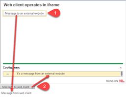
Fig. 497. Web client in iframe
Numbers refer to the following:
-
If you click Message to external website, Message from web client is displayed below the Message to web client button.
-
If you click Message to web client, It's a message from an external website is displayed in the web client messages panel.
Web client operates in iframe refers to data processor form representation where text is defined in 1C:Enterprise language. In your case, instead of this text, a message defined in the form of your infobase will be displayed.
The if (origin === '%WebSiteURL%') condition is generally required on a page, if one handler is used for several applications embedded in a single page. In this case, it is required to identify the web client sending a message.
Web client startup command line specified upon initialization of the webClientURL: webClientURL: '%WebSiteURL%/?%InfobaseName%MainWindowMode=EmbeddedWorkplace' property can contain authentication parameters. For instance, if a user performs authentication on a web page (or website in general), and the web page can unambiguously convert the website user name into username and password for an application. In this case, place the web client startup command line in a variable and generate it before the web client embedded in the web page is started.
In conclusion, consider one more thing. During web client loading, a screen saver and loading progress bar are displayed. If a web client is integrated into a web page, a screen saver and loading progress bar are displayed in the similar container where the web client is integrated. If it is not required, you can manage visibility of a web page area using the visibility CSS property. This way, the line to define the web client container on a web page looks as follows:
<div id="webClientContainer"
style="visibility: hidden"></div>To make the container visible, register a function to process the onStart event received from the web client:
events:
{
onStart: onStartWebClient, onMessage:
onWebClientMessage
}Further, write this function next to onWebClientMessage():
var onStartWebClient = function ()
{
document.querySelector('#webClientContainer').style.visibility
= "visible";
};When apply the changes described above, the web page will display no information until web client loading is completed. After that, the application interface will be displayed on the web page immediately.
18.2. Progressive web application
18.2.1. General information
Progressive web application or PWA is a technology in web development that allows you to visually and to some degree functionally convert a website into an ordinary application that runs on a PC or a mobile device. You can install a progressive web application on a user device and further use it as an ordinary application for the operating system installed on that device. Therefore, using a progressive web application may be subtly distinguishable or completely indistinguishable from using an application specifically designed for the operating system on the device. 1C:Enterprise web client can be used as a progressive web application if HTTPS protocol is used for connection to a web server and if a valid certificate is installed on such web server. Using web client as a progressive web application depends not only on the web client itself, but also on the web browser in use. Web browsers that support progressive web applications are specified in the system requirements.
You can specify an application name for a progressive web application. This name will be displayed:
-
In the installation/deletion window of the progressive web application.
-
In the main menu of the progressive web application.
-
In the picture name of the progressive web application in the Start menu or on the desktop.
This name is also used during the installation of the progressive web application and its further operation. If you change the name, reinstall the progressive web application to refresh the name. The name length is limited to 45 characters. If it exceeds 45 characters, it is displayed partially with an ellipsis at the end.
There are several ways you can specify a progressive web application name. They are listed below in descending priority:
- Use the ProgressiveWebApplicationName command in the web client startup command line.
This method is recommended if, for example, the infobase uses the data separation feature. In this case, each area must have its own name that must be specified upon starting the respective web client.
- In web client publication settings or using the default.vrd file of respective publication.
This method is recommended if the progressive application name differs from the one specified in configuration properties.
- If the progressive web application name is not specified using the methods mentioned above, the configuration presentation will be used as the application name.
18.2.2. Application programming interface
The progressive web application itself does not provide any special features to the application. However, 1C:Enterprise allows you to:
-
Check whether PWA installation on a user device is possible.
-
Install the progressive web application on a user device.
-
Get information on the active application mode.
To access PWA methods, use the progressive web application manager. To make is available, use the ProgressiveWebApplication global context property.
Before you install the application, check whether installation of the progressive web application is supported for your device. To perform the check, use the Supported() method. If the device supports PWA, you can install it.
During PWA installation, several methods are used:
-
IsInstalled() informs you on whether the PWA is already installed on the device or not.
-
BeginInstallation() starts PWA installation. Before the actual installation, the web browser will show the user a dialog box, in which the user has to confirm the installation or decline it. To get the result of this action, use the following method. There is another way to get the same dialog box:
-
In web client, click (+) on the right side of the browser address bar.
-
In the Service and settings web client menu, click Display as a separate application.
-
-
AttachInstallationCompleteHandler() allows you to register the callback handler that takes control after the user submits an answer in the web browser dialog box displayed before PWA installation.
-
DetachInstallationCompleteHandler() allows you to detach the handler attached by the previous method. It is reasonable to use the method if the previously attached handler of installation completion is no longer required.
The developer can check the current application mode using the CurrentMode() method:
-
If the progressive web application is installed and opened in a separate window, the method will return the ProgressiveWebApplicationMode.InStandaloneWindow value.
-
If the progressive web application is installed and opened in a browser tab, the method will return the ProgressiveWebApplicationMode.InBrowserWindow value.
-
In other cases, including calling the method in thin or thick client applications, the method will return the Undefined value.
Chapter 19. Job feature
19.1. General information
Use the job feature to execute an application functionality according to a schedule or asynchronously.
The job feature allows you to:
-
Define scheduled procedures at the configuration stage.
-
Perform specified actions according to the schedule.
-
Call a procedure or function asynchronously without waiting for its completion.
-
Track the execution of a certain job and receive its completion status (the value that indicates its successful or unsuccessful execution).
-
Get a list of current jobs.
-
Wait for the completion of one or more jobs.
-
Manage jobs (cancel, lock jobs, and so on).
The job feature consists of the following components:
-
Background jobs
-
Metadata of scheduled jobs
-
Scheduled jobs
-
Job scheduler
Background jobs execute application jobs asynchronously and are implemented by 1C:Enterprise language tools.
Scheduled jobs perform application jobs according to a schedule. Scheduled jobs are stored in the infobase. They are created based on the metadata defined in the configuration. Schedule job metadata contains such information as name, method, use, and so on. Actual execution of the scheduled job is performed by the background job which the job scheduler launches.
The scheduled job has a schedule that defines the time when the method related to the scheduled job must be executed. As a rule, the schedule is set in the infobase, but it also can be set at the configuration stage (for example, for predefined scheduled jobs).
Job scheduler is used to plan scheduled job execution. For each job, the scheduler regularly checks whether the current date and time correspond to the ones set in the job schedule. If they do, the scheduler assigns this job for execution. To do this, the scheduler creates a background job that performs actual processing for this scheduled job.
This feature can implement the situation where one background job is being executed at a time. To do this, you need a background or scheduled job key. Any application value can act as the key. Uniqueness of running background jobs is performed separately for background jobs launched from 1C:Enterprise language (independent background jobs) and background jobs launched using the scheduled jobs (scheduled background jobs). For independent background jobs, only one background job with a certain key value and background job method name can be executed at a time. The method name consists of a module name and a procedure/function name.
For scheduled background jobs, only one background job with a certain key value and generated by a specific scheduled job can be executed at a time.
So, a key groups running background jobs by the specific applied characteristic so that only one background job can be executed within one group (separate for independent and scheduled background jobs).
19.2. Background jobs
19.2.1. General information
Background jobs can be handy for complicated calculations whose execution might take an extended period of time. The job feature has tools to perform such calculations asynchronously.
The background job is related to the method called upon background job execution. The background job method can be represented by any procedure or function of a non-global common module. This procedure can be called on the server. Background job parameters can be represented by any values that can be passed to the server. Such parameters must fully match the parameters of the procedure or function the job calls. Background job parameters in serialized form cannot exceed 1GB. Otherwise, an exception is thrown. If the background job method is a function, its return value is ignored.
Creation and control of background jobs is executed programmatically from any join. Any user can create background jobs. Such jobs are executed on behalf of the users who created them. Receiving jobs, as well as expecting their completion is allowed from any join for a user with administrative rights or for a user who created these background jobs.
Background job is a purely session object, but it does not belong to any user session. A specialized session is created for each job, which is executed on behalf of the user who performed the call. Background jobs do not have a savable state.
The background job can create other background jobs. In client/server mode, this allows threading of complicated calculations among working processes of the cluster. That can considerably increase calculation performance. Threading is implemented by creation of several subordinate background jobs whose completion is expected in the main background job.
The background job can place data in the temporary storage of the calling session. For example, it can be used to pass a generated report or data prepared for processing to the calling session. Data transfer from the calling session to the background job session is impossible.
Background job startup is executed in the following way:
-
The following service actions are performed:
-
The fact of background job startup is committed to the event log (see Event log).
-
The parameters of connection with external data sources are set (see External data sources).
-
Interface mode is set, and so on.
-
-
The SessionParametersSetting event handler is executed in the session module (see Session module).
-
The background job is executed.
Successfully completed or terminated background jobs are deleted after twenty-four hours. The history of background and scheduled jobs has the following features:
-
The history is kept for each infobase.
-
The execution history is kept:
-
Background jobs: no more than 1,000 jobs.
-
Scheduled jobs: no more than 1,000 jobs. At the same time, the application tries to store not less than 3 latest startups for each unique scheduled job. When the general restriction of 1,000 startups is exceeded, the application tries to store the 2 latest startups for each scheduled job, and then 1.
-
System background jobs: no more than 1,000 startups. This section covers background jobs initiated by the system to perform some actions (execute reports, search, and so on).
-
19.2.2. Background job operations from 1C:Enterprise language
Note. Note. The examples provided in this section are not considered finished. They only demonstrate the way background job function.
Background jobs can be controlled over the background job manager: BackgroundJobs. You can use it to:
-
Execute a background job and pass its parameters: BackgroundJobs.Execute(). After a background job is started, an object that describes the started background job is returned: BackgroundJob.
-
Get a list of filtered background jobs using the BackgroundJobs.GetBackgroundJobs() method or find a background job by UUID using the BackgroundJobs.FindByUUID() method.
-
Wait for completion of one or several background jobs earlier started with specified waiting time. Use the BackgroundJob.WaitForExecutionCompletion() or BackgroundJobs.WaitForExecutionCompletion() for that.
Let us consider all the stages in more detail.
If you want to start a background job, you need an exportable procedure or function described in a non-global common module available on the server. The parameters of the called method must be listed in a special parameter array. The order of parameters in the method must fully match the order of array elements: the leftmost parameter corresponds to the array item with index 0. All background job parameter values must support serialization. Then the key and the description of the started background job is passed. The key is used for ensuring the uniqueness of the started background job.
The common module export method called ExportData(), located in the common CommonModuleBackground server module, will be used as a background job:
Function ExportData(DataDescription, PathToFile)
Export
// Data export
is performed here
EndFunctionTo start a background job, do the following:
CallParameters = NewArray;
CallParameters.Add(ExportedData);
CallParameters.Add("c:/temp/data.dat");
ExportJob = BackgroundJobs.Execute("CommonModuleBackground.ExportData", CallParameters, "DataExport", "Data export to a disk
file");The ExportedData variable value will be passed as the DataDescription parameter. The c:/temp/data.dat string will be passed as the PathToFile parameter value. The DataExport uniqueness key and a description will be set for the started background job.
At the start, waiting for background job completion is not performed. Instead, after creation of a specialized background job session and start of the background job execution method, control will return to the called code. The return value of the BackgroundJobs.Execute() method will be an object of the BackgroundJob type that describes the started background job. This object will be placed in the ExportJob variable.
The background job description will allow you to get background job ID used for background job search (the UUID property of the BackgroundJob object). When you check the background job status using the Status background job property, remember that this status is committed at the moment the BackgroundJob object is created and is not refreshed afterwards. To check the status, you need to get the description of the background job being checked before each check:
ExportJob = BackgroundJobs.FindByUUID(ID);If necessary, you can terminate a particular background job instance by using the BackgroundJob.Cancel() method. Remember that "garbage collection" is required after background job termination. For example, you need to delete temporary files that could be created by a terminated background job.
After the background job is started, you might need to periodically check the job execution status. Use the BackgroundJob.WaitForExecutionCompletion() method for that. As the method parameter, specify the time during which background job status change is expected. In any case, the method is terminated within the specified timeout. As a result, the method generates the BackgroundJob object, which describes the current background job status (including the Status property).
Thus, expectation of termination of the background job may be executed as follows:
While True Do
ExportJob = ExportJob.WaitForExecutionCompletion(10);
If ExportJob.Status = BackgroundJobState.Active Then
// continue
waiting for termination
Continue;
Else
// the
background job is terminated
Break;
EndIf;
EndDo;In the example, the timeout is set to 10 seconds (the WaitForExecutionCompletion() method parameter). If the background job is not terminated within 10 seconds, the termination expectation loop continues. If the background job stops (stops being active), the particular termination reason will be clear after the BackgroundJob.Status property analysis.
Note that waiting for completion is also possible for multiple background jobs. The background job manager has a similar method for that: BackgroundJobs.WaitForExecutionCompletion(). The difference is that instead of one object, you need to pass an array of BackgroundJob objects whose completion you want to track as the method parameter.
Background jobs can generate messages to users during their execution. The UserMessage object is used for that. The BackgroundJob.GetUserMessages() method is used to get such messages. Messages can be received during background job execution and after their completion.
19.2.3. Background jobs and extensions
When the background job has started, the extensions that were attached in the parent session will be attached in the background job session. At the same time, you can start a background job so that all extensions registered for the current infobase and the current separator set are attached in the background job session. To do this, use the ConfigurationExtensions.ExecuteBackgroundJobWithDatabaseExtensions() method. However, some scenarios may require starting a background job without any configuration extension. In this case, use the ConfigurationExtensions.ExecuteBackgroundJobWithoutExtensions() method.
19.3. Scheduled jobs
Scheduled jobs are used when you need to perform particular periodic or one-time actions according to a schedule.
Scheduled jobs are stored in the infobase. They are created based on the metadata defined in the configuration. Metadata define such scheduled job parameters as called method, name, key, applicability, predefinition flag, and so on. When you create a scheduled job, you can also specify its schedule (it can be set in the metadata), method parameter values, name of the user on whose behalf it will be executed, and so on.
You can create and manage scheduled jobs programmatically from any join if you have administrative rights.
Note. Note. In file mode, you can create and edit scheduled jobs without the job scheduler.
The method called upon scheduled job execution is linked to the scheduled job. The scheduled job method can be any procedure or function of a non-global common module that can be called on the server. Any values that can be passed to the server can be scheduled job parameters. Such parameters must fully match the parameters of the procedure or function the job calls. If the scheduled job method is a function, its return value is ignored.
While configuring, you can define predefined scheduled jobs. Predefined scheduled jobs do not differ from ordinary scheduled jobs, except for the fact that they cannot be explicitly created and deleted. If a job is marked as predefined in the scheduled job metadata, it will be created automatically in the infobase upon configuration update. If the predefined checkbox is cleared, the predefined scheduled job will be automatically deleted from the infobase upon configuration update. You can set initial property values of predefined scheduled jobs (for example, the schedule) their metadata. You can later change them during application runtime using corresponding 1C:Enterprise language methods. Changes in properties of predefined scheduled jobs already created in the metadata will have no effect on the actual parameters of these jobs in the infobase. Predefined scheduled jobs do not have parameters.
The scheduled job schedule defines the time it must be triggered. Use the schedule to set:
-
Date and time of job execution start and end.
-
Execution period.
-
Weekdays and months of scheduled job execution, and so on. For details, see 1C:Enterprise language description).
Examples of schedules of scheduled jobs:
| Schedule | Parameter values |
|---|---|
| Every hour, one day only | DaysRepeatPeriod = 0 RepeatPeriodInDay = 3600 |
| Every day once a day | DaysRepeatPeriod = 1 RepeatPeriodInDay = 0 |
| One day, one time | DaysRepeatPeriod = 0 |
| Every other day, once a day | DaysRepeatPeriod = 2 |
| Every hour 01.00 - 07.00 every day | DaysRepeatPeriod = 1 RepeatPeriodInDay = 3600 BeginTime = 01.00 EndTime = 07.00 |
| Every Saturday and Sunday at 9.00 | DaysRepeatPeriod = 1 WeekDays = 6, 7 BeginTime = 09.00 |
| Every day one week, one week off | DaysRepeatPeriod = 1 WeeksPeriod = 2 |
| At 01.00 once | BeginTime = 01.00 |
| Last date of each month at 9.00 | DaysRepeatPeriod = 1 DayInMonth = -1 BeginTime = 09.00 |
| The fifth date of each month at 9.00 | DaysRepeatPeriod = 1 DayInMonth = 5 BeginTime = 09.00 |
| Second Wednesday of each month at 9.00 | DaysRepeatPeriod = 1 WeekDayInMonth = 2 WeekDays = 3 BeginTime = 09.00 |
You can check if the job is executed for the given date. To do it, use the ExecutionRequired() method of the ScheduledJobsSchedule object. Scheduled jobs are always executed on behalf of a certain user. If the user of the scheduled job is not specified, execution is performed with the rights defined by a set of roles specified in the DefaultRoles configuration property. If no role is specified in this property, execution is performed without access rights restriction.
Scheduled jobs are executed using background jobs. When the scheduler determines that a scheduled job must be started, it automatically creates a background job based on this scheduled job. This background job performs all further processing. If this scheduled job is already being executed, it will not be started again regardless of its schedule.
Scheduled jobs can be restarted. It is especially relevant when the scheduled job method has to be executed. Scheduled jobs are restarted in case of their termination or in case of termination of the working process (in client/server mode) or client process (in file mode) where they are being performed. In the scheduled job, you can specify the number of times it must be restarted. To do it, use the Restart count on failure property. To specify the interval between restarts, use the Repeat interval on failure property. After the specified number of restarts is completed, restart attempts stop until the next time the terminated scheduled job is started according to the schedule. At the same time, the counter of restart attempts is reset. In case of another termination, the restart process is repeated from the beginning.
When you implement the restarted scheduled job method, keep in mind that it will be executed from the beginning rather than from the termination point.
19.4. Executing background jobs in different environments
Background job execution mechanisms differ depending on where the background job is executed.
19.4.1. File mode
Background and scheduled jobs are executed by client applications or web server extensions. Background jobs are executed in the client application that initiated their start. Background jobs are executed sequentially, so two background jobs cannot be executed simultaneously in one client application. If you use a web server for operation, consecutive execution of background and scheduled jobs is available for each infobase with access via this web server.
Behavior of background and scheduled jobs in file mode has the following features:
-
Information on the background jobs called using language methods or running reports is available only in the client application (or web server extension) that executed them. Therefore, key uniqueness control is performed on each client separately, independently of other clients. Information on completed background jobs is not saved after the client application (or web server extension) is closed.
-
The information on background jobs initiated by scheduled jobs is available in all client applications and is saved between starts.
-
Scheduled jobs are executed by one client application only. You can prohibit startup of scheduled jobs by a certain client application or forcibly assign scheduled jobs to a particular client application. To do it, use:
-
The /AllowExecuteScheduledJobs command-line parameter for thick and thin client applications.
-
The allowexecutescheduledjobs attribute of the point item of the default.vrd publication file in case of infobase publication on the web server.
-
-
Scheduled jobs are executed by the first client application according to the start order, for which execution of scheduled jobs is not prohibited. When this client application session is completed, execution continues in any of the remaining running client applications. If a client application explicitly assigned for scheduled job execution is started, scheduled jobs are started in this client application regardless of any other available applications (including web server extensions).
-
Scheduled jobs are performed by the web server extension as long as the web server extension serves at least one client session.
-
If according to the scheduled job schedule, no client application is active at the time of background job start, such background job will never be performed.
-
Scheduled jobs are processed once in 60 seconds.
-
The background job scheduler is initialized in 60 seconds after the client application start or after an attempt to start the first background job. The following operations are performed before the background job scheduler is started in synchronous mode: search in the dynamic list, generation of reports, search for input by string, and global search.
-
The scheduled job scheduler is initialized in 60 seconds after the background job scheduler is started. Therefore, execution of scheduled application jobs begins in no more than 120 seconds after the client application start.
-
Background jobs not completed within 30 seconds after client application shutdown are forcibly terminated. In this case, the following event is recorded to the event log: Background job Force termination ($Job$.Terminate).
-
Scheduled jobs are not supported in file infobase mode in the session that was received using the automation-server 1C:Enterprise or COM-connection. If background jobs are created in such session, they are placed in a queue, but not started.
19.4.2. Client/server mode
The Job scheduler located in the cluster manager is used in client/server mode to perform background jobs. The scheduler receives a working process that is least loaded for all the background jobs in the queue for execution and uses it to execute the respective background job. The working process executes the job and notifies the scheduler of the execution results.
In client/server mode, you can lock execution of scheduled jobs. Scheduled jobs are locked in the following cases:
-
Scheduled jobs are explicitly locked for the infobase. Lock can be set via the cluster console.
-
Session start lock is set for the infobase. Lock can be set via the cluster console.
-
The SetExclusiveMode() method set to True is called from 1C:Enterprise language.
-
In some other cases (for example, when the database configuration is updated).
19.4.3. Mobile application
Background jobs are executed by the mobile application. Background jobs are executed sequentially. Two background jobs cannot be executed on a mobile device simultaneously.
Behavior of background jobs on mobile devices is described below:
-
Mobile devices do not support scheduled jobs.
-
The background job scheduler is initialized after an attempt to start the first background job. The following operations are performed before the background job scheduler is started in synchronous mode: search in the dynamic list, generation of reports, search for input by string, and global search.
-
Background jobs not completed within 30 seconds after client application shutdown are forcibly terminated.
19.5. Creating scheduled job metadata
Before a scheduled job can be programmatically created in the infobase, you need to create a configuration object for it.
To create the configuration object of a scheduled job, execute the Add command in the Common configuration tree branch for the Scheduled jobs branch.
The scheduled job has a number of properties described below.
Method name. Scheduled job method name.
Key. Arbitrary string value to be used as a scheduled job key.
Schedule. Scheduled job schedule. To generate a schedule, follow the Open link and set the required values in the opened form.
On the Common tab, specify the job start and end date and repeat mode.
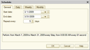
Fig. 498. Common schedule
On the Daily tab, specify the daily job schedule.
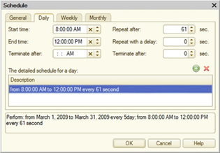
Fig. 499. Daily schedule
In the schedule, you can specify:
-
Job start and end time. The job starts automatically only within the time interval.
-
Job timeout.
-
Job execution frequency.
-
Period between job execution.
-
Execution duration.
You can combine these conditions.
On the Weekly tab, specify weekly job schedule.
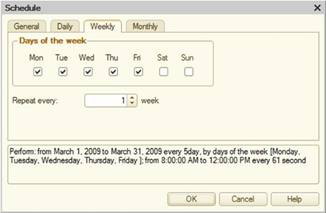
Fig. 500. Weekly schedule
Select the checkboxes for the weekdays when the job will be executed. If you need to repeat the job, indicate the repeat interval in weeks. For example, if a job must be executed every 2 weeks, set the repeat value to 2.
If a weekly schedule is set, and the Repeat every property value is more than 1, the First weekday property set in the regional infobase settings will be considered to determine week borders.
On the Monthly tab, specify the monthly job schedule.
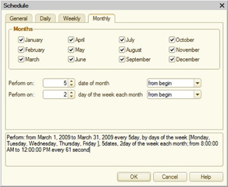
Fig. 501. Monthly schedule
Select the checkboxes for the months when the job must be performed. If necessary, you can specify a particular day of the month or the week for job execution from the month/week start or end.
When writing a scheduled job, it is checked whether the job can be launched according to the specified schedule. For example, the scheduled job is saved on 09/12/2021 at 12:33.
If the job schedule is set to "every day, from 1:00:00 once a day", the job will be executed right after saving and every day at 1:00 after that as specified in the schedule.
If you change the schedule to "every day, from 1:00:00 to 1:01:00 once a day", the job will not be executed after saving as the saving time is outside the scheduled launch interval. Later, the scheduled job will be performed on schedule: every day at 1:00.
Use. If it is set, the job will be executed according to the schedule.
Predefined. If it is set, the job is considered predefined.
Restart count on failure. Indicates the number of restart attempts upon abnormal termination.
Repeat interval on failure. Indicates the interval between restart attempts upon abnormal termination.
For example, this way you can create a background job for "Full-text search index update":
BackgroundJobs.Execute("FullTextSearchIndexUpdate");And this way you can create a scheduled job for "Sequence restoration":
Schedule = New JobSchedule;
Schedule.DaysRepeatPeriod = 1;
Schedule.RepeatPeriodInDay = 0
Job = ScheduledJobs.CreateScheduledJob("RestoreOfSequences");
Job.Schedule = Schedule;
Job.Write();Chapter 20. Full-text search in data
20.1. General information
The 1C:Enterprise feature of full-text search in data allows you to search for information in databases using search operators (AND, OR, NOT, NEAR, and more) and hashtags (strings of #Hashtag type). Full-text search is based on two components:
-
A full–text search index is a special dictionary that contains all the words that are stored in indexed objects and the places of the infobase where these words occur. This index is created and maintained by the platform.
-
Full-text search tools.
Full-text search objects are data of the following configuration objects:
-
Exchange plans
-
Catalogs
-
Documents
-
Charts of characteristic types
-
Charts of accounts
-
Charts of calculation types
-
Information registers
-
Accumulation registers
-
Accounting registers
-
Calculation registers
-
Business processes
-
Tasks
The Full-text search property is implemented for each of the listed configuration objects. You can use it to include and exclude object data in/from full-text indexing.
1C:Enterprise has an event log to record changes of full-text search objects. Records are added to this log at the same time objects are saved to the database. Only objects set up for full-text indexing are added to change registration files. If transaction cancellation cancels object registration in the database, its record remains in the event log.
Full-text indexing is executed in privileged mode (in the server context) and does not require an exclusive capture of the database. In the process of full-text indexing, change registration files are read and changed objects are received from the database. Also, words are transliterated, and Latin letters in words are replaced with Cyrillic letters (the index keeps both word forms). Only attributes of the following types are to be indexed:
-
String
-
Date
-
Number
-
Reference types
-
Value storage
For each object and attribute, you can add the following to the full-text index:
-
Metadata object name or its attribute name
-
Metadata object synonym or its attribute synonym (in all configuration languages)
-
Metadata object presentation (in all configuration languages)
Standard and custom attributes are indexed in all languages, which ensures search in all configuration languages (for example, in Russian and English).
There are two full-text search versions in 1C:Enterprise. Version 1 is supported since the first release of 1C:Enterprise version 8.3. Version 2 is supported since 1C:Enterprise version 8.3.22. Both full–text search versions provide full-text search in data. However, version 2 uses computer resources more efficiently, works faster, and contains a number of extensions in the data search language. If the behavior of any feature described in this section differs in different search versions, this will be explicitly specified.
The full-text search index works slightly differently in different search versions:
- Version 1. When full-text indexing is performed, the main index is created. Upon the next database data change, an additional index is created. It contains all the information on the data changed after the latest main index update.
Searching with the main index is performed effectively, while searching with the additional index is performed more slowly. For that reason, indexing supports index merging. It allows adding the result of latest changes to the main index. Note that this operation might be time-consuming if the main index size is large. For that reason, the recommended periods for this operation are at night or on weekends, as they are the least loaded.
The index is updated using a background job that needs to be implemented by the application developer.
- Version 2. This version does not separate indexes into main and additional ones. Upon initial filling, a single index is generated. As the data in the infobase changes, the system automatically updates the index to keep the index up to date. This does not require any actions from the application.
Full-text search is initiated by the user in the client application, but the entire search API is available only on the server. In file mode, search will be performed on the client computer. In client/server mode, it will be performed in the 1C:Enterprise server cluster. Remember that full-text search version 2 is not supported in file infobases (except when using the file infobase with a standalone server).
Full-text search in data is performed according to user rights. That includes user rights restrictions at the level of database records and fields. You can search for words that were entered in the database with mistakes. For example, if the English letter "c" is typed in the word "русский" instead of the Russian letter "с" or if the keyboard layout was accidentally changed while typing a word resulting in the word "системf" instead of "система", such words will still be included in the search results. Also remember that full-text search in data is always performed from the word beginning. The search string cannot contain more than 1,000 words, excluding logical and special search operators. If the number of words in the search string exceeds the specified limit, the search is not performed and an exception is thrown.
If a hashtag is specified in the search (for instance, #Order), all objects in indexed data that contain the said hashtag will be found. If you need to find all objects with hashtags starting from a certain sequence of symbols, specify after that sequence. Specifically, if you need to find all hash tags starting from Order, specify #Order in the search string. In this case, #Order, #OrderExternal, #OrderInternal and similar items will be found.
Search results are returned in parts whose size is defined upon execution of the full-text search command.
Received results are ranged according to the following priorities:
-
Word "weight". A word can get more "weight" using the full-text search query language.
-
Metadata object "weight". It is directly proportional to the number of links to the object in the attributes of other objects.
-
Object date. New objects will be shown first.
20.2. Using the feature
Full-text search in data is performed by 1C:Enterprise language tools.
The FullTextSearch global context property returns the full-text search manager: an object of the FullTextSearchManager type. The methods of the full-text search manager allow you to perform all the necessary operations for managing and using full-text search. Calling API methods will look as follows: FullTextSearch.CalledMethodName(). For simplicity, the name of the global context property will be omitted in the following text. Such simplification is not allowed in examples and real code.
The platform provides an API to manage the full-text search:
-
GetFullTextSearchMode(). Returns the value of the FullTextSearchMode system enumeration. If the value is set to Allow, you can use full-text search. If the value is Deny, you cannot use full-text search and perform any related actions.
-
GetFullTextSearchVersion(). Returns the current version of full-text search.
-
UpdateDate(). Date of the latest data indexing when there was no information on new objects for indexing.
-
IndexTrue(). Returns True if the full-text search index fully matches the current status of the infobase. In full-text search version 2, the method can return opposite values if there are many changes in the indexed data and calls are frequent and consecutive.
-
IndexUpdateComplete(). The behavior depends on the full-text search version:
-
Version 1. Returns True if full-text index merging is not required.
-
Version 2. Returns False if the IndexTrue() method also returns False. In all the other cases, it returns True as the index merging is not required.
-
-
GetMaxIndexedDataSize(). Returns the maximum size of data (in bytes) indexed by the full-text search.
-
SetMaxIndexedDataSize(). Allows you to set the maximum size (in bytes) of data stored in a single configuration object attribute and indexed by the full-text search. The maximum size of indexed data is equal to 1 MB for the first call of this method.
-
GetIndexingJobsCount(). Returns the number of background jobs that perform data indexing at the same time.
-
SetIndexingJobsCount(). Allows you to specify the number of background jobs that will be involved in data indexing at the same time. You can change the number of the jobs depending on the system load. For example, if you have much data to index, you can set many indexing jobs when the system load is minimal and one background job when the load is maximum.
-
GetCompositeWordsSeparationMode(). Allows you to get the separation mode of meaningful word parts. It is not used in full-text search version 2.
-
SetCompositeWordsSeparationMode(). Allows you to set the separation mode of meaningful word parts. To switch the composite word separation mode, you need to rebuild the full-text search index. It is not used in full-text search version 2, but the parameter is saved in the infobase. The value is considered when you migrate to full-text search version 1.
The following methods are used for full-text indexing:
-
SetFullTextSearchVersion(). With it, you can specify the full-text search version that will be used in the infobase. To change the version, get exclusive access to the infobase. The behavior depends on how you change the version:
-
Migrating from version 1 to version 2:
-
The system checks whether you can run full-text search version 2. If not, it cancels the migration and throws an exception with the reason why version change is impossible.
-
All new background jobs of full-text search index update will run with full-text search version 2.
-
All new connections to the infobase will use full-text search version 2.
-
The current index state of version 2 will be used. If the existing index is outdated or was not created, search attempts will be limited to the current index state.
-
The index of full-text search version 1 will stay as it is. If you no longer need the index, clear it before changing the version.
-
-
Migrating from version 2 to version 1:
-
All running background jobs will be cancelled.
-
The system cancels updating the index of full-text search version 2.
-
All new connections to the infobase will use full-text search version 1.
-
The index of full-text search version 2 will stay as it is. If you no longer need the index, clear it before changing the version.
-
-
You can change the full-text version in exclusive mode. It means that the person who changes the version fully controls the entire process. Any infobase changes which can influence the index and indexing necessity are unlikely. If the migration does not go smoothly, you can return to the previous version pretty fast. The full-text search index will be used to search for the required data, as it is up-to-date and has been saved upon migration.
-
SetFullTextSearchMode(). Sets the full-text search mode (Allow or Prohibit). If the search is prohibited, calling this method with the Allow parameter automatically clears the existing full-text index.
-
UpdateIndex(). Updates the full-text search index. If indexes there are no existing indexes, it performs full reindexing of the whole database. The behavior depends on the full-text search version:
-
Version 1. The method returns either after the index is fully updated or after the next portion is updated (depending on the Portion parameter value). Indexing conditions are passed in the parameters of the method:
-
EnableJoining. If True is passed, the main and additional indexes are merged.
-
Partial. If set to True, indexing is performed in portions of 10 thousand objects. The process finishes after indexing the data of one portion. The indexing time of one portion considerably depends on the data.
-
-
Version 2. The method starts updating the full-text search index and immediately shuts down. The index is updated asynchronously in the background. To find out the indexing state, use the IndexTrue() method.
-
-
ClearIndex(). Deletes all files of the full-text index. This method is recommended in case of full or almost full data update (for example, upon infobase import). You may need to rebuild the index after clearing. Clearing the index depends on the full-text search version:
-
Version 1. The index is cleared synchronously. If the method is completed, it means that the index is cleared.
-
Version 2. The index is cleared asynchronously. Control returns without waiting for any action. If an indexing job is being performed during the method call, it will be terminated automatically.
-
The full-text search process in data is initiated with the CreateList() method. Two parameters are passed into the method:
-
SearchString. String with the search expression.
-
PortionSize. Number of objects to be returned in one portion of the full-text search.
For a description of the search expression syntax, see Full-text search expressions.
The CreateList() method returns the FullTextSearchList object, which ensures full-text search performance and getting full-text search results. This object can be used repeatedly for performing search with different conditions. Use the SearchString and PortionSize object properties to change the used search expression and the portion size of received data.
Use the FirstPart() method to perform full-text search and get the "first" results. The method fills the list with the first found items according to the portion size. Use the NextPart() and PreviousPart() methods to get further full-text search results. These methods can accept the current initial position as the parameter and fill the full-text search list with search results. If the CurrentStartPos parameter is not specified, the value of the initial position of the FullTextSearchList object is used. For example, this value can be received using the StartPosition() method. The parameter is preferred, as it increases the full-text search speed.
The Count() method contains the number of items in the current portion (it will be less than or equal to the portion size for the last portion). The TotalCount() method contains the total number of items found as a result of full-text search.
The NextPart() method fills the list with the following items in accordance with the portion size value. Along with that, the current position increases by the data amount in the received portion. If there is no more data left to get another data portion, an exception is thrown. To process it, you can use the Try ... Except ... EndTry structure.
The PreviousPart() method fills the list with previously found items in accordance with the portion size. If there is no data more data left to get another data portion, an exception is thrown. To process it, you can use the Try ... Except ... EndTry structure.
The TooManyResults() method returns True if some search results have been excluded for performance reasons. This might affect the search accuracy (not all the objects will be found). It makes sense to analyze the value returned by this method after getting the last portion of found data to inform the user about more results in the database that have not been received.
The LimitSearchString property allows you to specify that you need to check that the search string meets certain criteria when searching:
-
The total search string length does not exceed 1,000 characters.
-
The search string cannot contain more than 32 words.
If the LimitSearchString property is set to True and the search string does not meet the requirements specified above, the search is not performed, and an exception is thrown.
The GetDescription property contains the flag that the description of the search results has been received. If it is set to True, the Description value is filled for each of the search results, which helps to understand the context of the words found. At the same time, setting this property to False makes the search quicker.
The full-text search list represents a collection of full-text search list items, which can be iterated by the For Each ... In ...Do structure.
Each item of the full-text search list is represented by the FullTextSearchListItem object and contains the following properties:
-
Value. Identifies the data (object or record set), where the search expression was found.
-
Metadata. Metadata object that describes the data where the search expression was found.
-
Presentation. Text presentation of the found object.
-
Description. Contains <attribute>:<value> pairs, where:
-
<attribute> is the attribute of the object in whose value the search expression was found.
-
<value> is the value of this attribute.
-
The placement of the "attribute– value" pairs depends on the full-text search version:
-
Version 1. Each pair starts with a new line.
-
Version 2. All pairs are output in one line, separated by the ";" character. If there is not enough space, the attribute name can be omitted.
If you use theGetRepresentation() method, you can get the search result as an XMLReader object or as an HTML text string, where found words are highlighted by HTML means. The display of full-text search results may vary in different search versions.
20.3. Using additional dictionaries
Note. Note. This feature is supported only for full-text search version 1.
Additional dictionaries of morphology and synonyms for full-text search expand system dictionaries and can contain special terms and words that are used for configuration operations.
Additional dictionaries can be represented by templates of binary data and text templates, as well as constants of the string or ValueStorage type. To specify additional dictionaries, use the Additional dictionaries property of the root metadata object.
They must contain the following:
<?xml
version="1.0"?>
<Dictionary>
<Words>
<lemma>connection</lemma><forms>connections</forms>
<lemma>index</lemma><forms>indexes
indices</forms>
</Words>
<Synonyms>
<item>error bug crash</item>
<item>stream thread</item>
</Synonyms>
<Roots>
<item>bread</item>
<item>house</item>
<item>post</item>
</Roots>
</Dictionary>Dictionary
The item is used to store the Dictionary. The Dictionary can contain two sections:-
Additional words (lemmas) and their forms
-
Rows of synonyms
Words
The item contains Words as follows:-
In the lemma item, the word is stored in its basic form (nominative case).
-
In the forms item, case forms of the word are stored.
Fuzzy search is not performed by default. To perform fuzzy search, use an asterisk (). For example, the search for connectio returns connection and connections.
Synonyms
The item stores synonym sets. Each set is enclosed in the item tags.For synonyms to participate in full-text search, specify an exclamation mark (!). This way, the search for !error finds error, bug, and crash. For a description of the search expression syntax, see Full-text search expressions.
The Synonyms and Words items can be specified in any order.
Roots
The item stores the glossary of meaningful word parts. Each meaningful word part must be included in item. For the languages different from Russian, the glossary of meaningful word parts dissects composite words and enables search by meaningful word parts.Dictionaries are loaded upon the first search call or indexing. If a template contains errors, dictionary filling stops at the place an error was found.
If you want to change an additional dictionary, restart the system to ensure the new dictionary is attached. Different components must be restarted depending on the application mode:
-
In file infobase mode with direct connection, restart all the client applications attached to the infobase.
-
In file mode with web server connection, restart the web server extension (actually, the web server requires restart).
-
In client/server mode with any connection type, restart 1C:Enterprise server.
In this case, the index is not updated automatically. You need to rebuild the index manually, although new dictionaries are used for search.
20.4. Keeping the full-text search index up-to-date
For a full-text search in data to actually search for data, keep the full-text search index up-to-date. To do this, add new information (new infobase objects) to the index, delete outdated information (which was located in deleted objects), and update information about modified infobase objects.
Depending on the full-text search version used by the application, such actions are performed in different ways. Let's take a look at these actions.
Version 1
To update a full-text search index, implement a scheduled job which will call the UpdateIndex() method. The job schedule must minimize delays between entering/changing information in the infobase and displaying this information in the index. As a rule, scheduled job is started every 60 seconds.
The scheduled job text may be as follows:
Procedure UpdateFullTextSearchIndex() Export
FullTextSearch.UpdateIndex(False, True);
EndProcedureThis scheduled job will perform a batch update of the index without merging the main and partial indexes. Batch indexing will slightly increase the initial index population, as 10,000 objects will be added to the index every minute. However, such index generation will have a positive impact on the overall system performance during the initial index population.
If needed, you can merge full-text search indexes. To do this, you can either implement a separate scheduled job or implement a merge in the same scheduled job, allocating a separate time interval with minimal system load.
Version 2
In this case, it is enough for the system administrator to initiate the initial population of the index using the standard Manage full-text search function. 1C:Enterprise will perform all other actions (including updating the index) automatically. Since the initial index population is required even for an empty infobase, you can insert the UpdateIndex() method call, for example, into the initial infobase population code.
When generating the version 2 index, the free space on the disk drive that stores the full-text search data directory is taken into account. Indexing will be interrupted if there is less than 10% free space on this disk drive. In this case, the index will become irrelevant, and data search will be impossible. Once there is enough free space on the disk drive, indexing will continue. After updating the index, the search will also be available.
20.5. Mobile platform
Full-text search on the mobile platform has some features and restrictions.
Full-text search does not support:
-
Full-text search version 2
-
Search with morphology
-
Attachment of additional dictionaries
-
Text extraction operation (the TextExtraction object).
When you use the full-text search on the mobile platform, remember the following features:
-
The full-text search index is updated automatically after creation or change of the configuration object for which full-text search is enabled.
-
To update the full-text search index, create a specialized background job. Such background job is created if there are no active server calls or other background jobs. Update is performed in portions of 10,000 objects.
-
If all infobase objects are indexed, the mobile platform starts merging of indexes after 20 seconds of inactivity.
If data indexing must be ensured, for example, after infobase synchronization with a PC infobase, you need to update the full-text search index explicitly using the UpdateIndex(True,False) method of the full-text search manager.
Chapter 21. Temporary storage functionality, handling files and pictures
21.1. Temporary storage
1C:Enterprise has the functionality of temporary storage providing storage of some data attached to the session. Besides, the mechanism of handling files is implemented, which provides for exchange of files between the infobase and the client application. This mechanism feature consists in its orientation for using in the thin client and the web-client, and is developed with account of restrictions on files, constrained by web browsers.
Temporary storage. This is a specialized information storage, where the value can be placed. The main purpose is to temporarily store information at the client/server interaction before it is transferred into the data base. The mechanism of temporary storage combined with the files functionality provides a set of methods, which allows you to place the data locally kept at the user, into the temporary storage of the infobase, to transfer this information from the temporary storage into the database and get it back into the user computer. The most widespread application tasks resolved by this functionality are keeping in-line information, for example, pictures of goods, documents related to contracts, and so on. Temporary storage and file management functionality is often used jointly, but it can be used separately.
The temporary storage is necessary, for example, when the web-client needs to transfer a file from a client computer to an application server computer (or web-server extension for a file variant of information base). The file is placed in the temporary storage and later (in 1C:Enterprise system server application) may be used for the object recording to a database or for processing.
When you place data into the temporary storage, you should remember that the temporary storage can contain the data with types that do not support serialization, both directly and as components of any collections.
You can use the temporary storage as a universal storage for the controlled data lifetime:
-
If you place data into the temporary storage and bound the data to some form, the lifetime of the saved data will depend on the lifetime of the form, to which the data are attached. When you delete the form object, the temporary storage will be cleaned of all the related information.
-
If attaching data to the form was not completed at placing the data into a temporary storage, clearance of the temporary storage will be performed in the following cases:
-
At the following query of the form.
-
At the following server call from the overall client module.
-
At the context and non-context client calls from the form.
-
At the server call from the command module. If a server call is performed for placing the value into the temporary storage, clearance will not be performed. Clearing is performed after the call completes its functioning.
-
It means that you can place one or a few values into the temporary storage, and use this value in the next call. Along with that, the replaced value will be automatically deleted after usage and before the server call is completed.
The most typical application task that can be solved by the temporary storage is providing access to files and pictures before the object is recorded in the infobase, for example, in the item form. When you arrange such access, it is recommended to pass data from the client computers to the server as files, without preliminary "transformation" into a text document, spreadsheet document or similar formats of the 1C:Enterprise. It is recommended to pass the file to the server side and on the server side, to load the file data into the required format 1C:Enterprise.
The data placed in the storage are identified by a unique address, which can further be used in operations of recording, reading, and deleting. This address is given by the recording methods of values in the temporary storage. A separate method in the 1C:Enterprise language allows you to determine if the passed address is the address that indicates the data in the temporary storage.
The temporary storage generated in one session is unavailable from another session. The exception is the capability of data transfer from a background job into a session, which initiated this background job, using the temporary storage (see Operating temporary storage in the background job).
21.2. Features of handling files in the asynchronous mode and in the web client
Handling files in the asynchronous mode is available on the side of the client application only. In the general case, you should use synchronous methods for work on the server side and asynchronous ones for working on the client application side.
Let us consider an example of handling files in the asynchronous mode: deleting all files in the directory of temporary files. This action will look as the follows for the synchronous mode:
&AtClient
Procedure Delete
(Command)
Try
DeleteFiles(TempFilesDir(), GetClientAllFilesMask());
Report("Delete successful");
Except
// error handling is performed here
ErrorDetails = ErrorInfo();
Message("An error occurred when performing a file operation:
" + ErrorProcessing.BriefErrorDescription(ErrorDetails));
EndTry;
EndProcedureAsynchronous mode will look as follows:
&AtClient
Async Procedure
DeleteTemporaryFiles(Command)
Try
Await DeleteFilesAsync(Await TempFilesDirAsync(), GetClientAllFilesMask());
Report("Delete successful");
Except
// error handling is performed here
ErrorDetails = ErrorInfo();
Message("An error occurred when performing a file operation:
" + ErrorProcessing.BriefErrorDescription(ErrorDetails));
EndTry;
EndProcedureYou should pay attention to the fact that almost all file operations are asynchronous. Even such simple actions as receiving a directory of temporary files. If an error occurs when executing file operations, it will be caught by Try – Exception.
Handling files in the web client has some features:
-
If you do not install plug-ins for handling files, in any browser, you have the methods available: GetFile(), BeginPutFile() and BeginPlacingFiles(). Capabilities of parameterization of the methods BeginPutFile() and BeginPuttingFiles().
-
The method BeginPutFile() (in the interactive mode) stops code execution in the 1C:Enterprise language in the thin and thick client, as opposed to the web client. The call of the callback procedure passed to theBeginPutFile() method will be performed after the method completion. To avoid behavior differences for thin and web clients, place the whole code to be executed after moving a file in the callback handler.
-
In web client, only asynchronous file operation methods are available. This behavior is not affected by the application property Modality use mode, see Specifying compatibility properties.
-
Installation of the file system extension gives more options for parameterization and asynchronous file operation methods. However, options for the synchronous file operation in the web client are unavailable in any operation mode.
-
The file system extension does not support HTTPS operation using the client certificate.
Note. Note 1. Microsoft Core XML Services (MSXML), vs 4.0 or 6.0 is recommended to be used for the correct operation of the file system extension in the web browser Microsoft Internet Explorer.
Note. Note 2. The file system extension for Microsoft Internet Explorer is installed to the directory %APPDATA%/1C/1CEWebExt/FileSystemExtIE.
21.3. File and temporary storage operation methods
21.3.1. General information
All file operations performed in the client application (including the file transfer between the client and server and the work with the temporary storage) are asynchronous in any client application and any variant of operation.
Installation of the file system extension might be required to transfer files from the web-client to the server. In the general case, it can be stated that an extension will be required only when a file operation is not accompanied by the user interactive action, for example, it will require an extension to place a file to a server with a fixed path specified in the code of the application solution. At the same time, a file specification with the help of file selection dialog will require no extension for the work with files.
21.3.2. Migrating file data to the temporary storage
21.3.2.1. Single file
To put a single file to the temporary storage, use the PutFileToServerAsync() method. Once the method is completed, the file will be migrated from the local file store to the temporary storage. Some auxiliary information can be specified when calling a method (depending on the method variant used). The following information can be specified:
-
The address in the temporary storage where you need to save the file (Address parameter). If no parameter is specified, a new item whose address will be transferred to the file transfer to temporary storage completion handler will be created. If the parameter is specified, the file will be put at the specified address. In this case, the data stored at the transferred address as of the method call will be deleted.
-
Description of a file to be put to the temporary storage. A file can be set interactively, in the file selection dialog, as a complete path to the file formed in the embedded language, as a special item formed when a file is put on the form items with the help of drag operation (FileRef object).
-
Description of the dialog to be opened for the selection of the file put to temporary storage (PutFilesDialogParameters object).
-
Form unique identifier. If this parameter is set, the platform will automatically delete all items of the temporary storage after the form with the specified ID is closed. Otherwise, the value will be deleted automatically after the next server call. If an ID that does not correspond to any form is specified as the parameter, the item of the temporary storage will be deleted upon the client session completion. But it will be more correct to delete an unused value from the temporary storage when this value is no longer used (by the global context method DeleteFromTempStorage()).
The method enables processing several events that emerge during the method operation:
-
The fact of the selection of the file to be migrated to the temporary storage. The parameter of BeforeStartPutFileNotifyDescription method is used for it. This notification will be called directly before the file is put to temporary storage. This handler has the option to retract the file migration if, for instance, the size of the migrated file is too big. If you retract the file migration in this handler, the system will not call the final handler.
-
A periodic event arising in the process of a file transfer to the server. For this, the parameter of ProgressNotifyDescription method is used. The information on the transferred file and on what part of the file is transferred to the server will be transferred to this event. If the developer implemented a special form displaying the transfer progress, it is possible to abort the file transfer to the server, for which it is necessary to set the developer's special parameter RetractFileMigration in the value True. If the CancelPuttingFile handler parameter is set to True for all files when putting several files, it will have the same result as setting the CancelPuttingAllFiles handler parameter to True. In any of these cases, the value Undefined will be transferred to the file migration completion notification handler.
You can get server file information when the Await statement gets the result of the PutFileToServerAsync() method. File information will be provided as the StoredFileDescription object.
Various types of values can be indicated as the description of the stored file as was said above:
-
No file name is specified. In web client, installation of the file system extension is not required. In this case, a selection dialog whose parameters are set by default will be offered to specify the file.
-
Full path to the file to put (PathToFile parameter). In web client, installation of the file system extension is required. In this case, an attempt to put the file the path to which is specified in the parameter to the temporary storage will be made.
-
FileRef object (is the parameter of the same name). In web client, installation of the file system extension is not required. An object of such type cannot be created in the embedded language. It can only be obtained in the result of interactive action. The file dragging from the operating system interface to any item of the client application form (including web-client) is such action.
-
FileSelectionDialogParameters object (DialogParameters parameter). In web client, installation of the file system extension is not required. This method call option is similar to the first one when no certain file is specified but is offered to be selected interactively. The described call option difference is that you can adapt the dialog to the real scenarios: specify a title, file selection masks. If you use the file selection dialog box with several specified filters when putting a file or files to the server, it is recommended that you create a filter that includes all allowed files and set this filter as default one.
Below is an example of file migration to the temporary storage, in which the file selection dialog is set and the process of the file transfer to the server is displayed. The example is for education only and is not a complete option of any mechanism implementation:
&AtClient
Async Procedure PutFileCommand(Command)
DialogParameters=New PutFilesDialogParameters;
DialogParameters.Header = "PutFileToServerAsync";
DialogParameters.MultiSelect
= True;
DialogParameters.Filter = "Text file|*.txt|All files|*.*";
ProgressCallback = New NotifyDescription("ProgressCallback", ThisObject);
BeforeCallback = New NotifyDescription ("BeforeCallback", ThisObject);
FileDescription = Await
PutFileToServerAsync(ProgressCallback, BeforeCallback, , DialogParameters);
Message("Store the
file" + ?(FileDescription.PutFileCanceled , "cancelled", "successful"));
Message("Temporary
storage address: " + FileDescription.Address);
Message("File Name:
" + FileDescription.FileRef.Name);
Message("File size, bytes: " + FileDescription.FileRef.Size());
EndProcedure
&AtClient
Procedure ProgressCallback(StoredFile, Stored, RetractFileMigration, AdditionalParameters) Export
State("File " + FileToPut.Name, Put, "File size, bytes = " + FileToPut.Size(), PictureLib.Document);
EndProcedure
&AtClient
Procedure BeforeCallback (FileToPut, CancelPuttingFile, AdditionalParameters) Export
Message("File to put - " + FileToPut.Name + ", file size, bytes = " + FileToPut.Size());
EndProcedureYou should know that indication of the filter list for parametrization of the dialog box does not make the user to select files only with these extensions or masks. Indication of files only makes it easier to select necessary files for the user.
To put a file on the server, you can use the following methods:
-
Synchronous method: PutFile().
-
Asynchronous method (callback): BeginPutFileToServer().
See also:
-
Synchronous and asynchronous methods (see Synchronous and asynchronous operations).
-
Dragging mechanism (see Drag and drop feature).
21.3.2.2. Several files
The general behavior of the PutFilesToServerAsync() method matches the one of the PutFileToServerAsync() method. The distinction is that the following is used for the transfer of description of several files:
-
String with a mask that describes files to put on the client computer hard drive. File system extension is required in web client. In this case, all files corresponding to the search string will be transferred to the server.
-
Array of objects that describe files to put. It is important to remember that the values of one type can be contained within the framework of one array call. The objects can be of the following types:
-
Type TransferableFileDescription. File system extension is required in web client. Each array element must contain a non-empty path to the file on the hard drive.
-
Type FileRef. No file system extension is required in web client. It can be used in the form to which different files are dragged from the client computer memory.
-
-
File selection dialog parameters for the user to indicate the files to be transferred to the server. No file system extension is required in web client.
The number and description of event handlers matches the events from the PutFileToServerAsync() method. The only difference is that an array of objects describing the files being processed is passed to each handler.
The event handler allows you to abort the transfer of only all selected files to the server before the migration beginning. The process of the files transfer to the server is consecutive. The process notification event handler is called for each file. This handler allows you to abort the transfer of any single file (with the help of the handler parameter RetractFileMigration) and the transfer of all files (with the help of the handler parameter RetractAllFilesMigration).
You can get server file information when the Await statement gets the result of the PutFilesToServerAsync() method. File information will be provided as an array of objects of the StoredFileDescription type.
To put a file on the server, you can use the following methods:
-
Synchronous method: PutFiles().
-
Asynchronous (callbacks): BeginPutFilesToServer().
See also:
- Synchronous and asynchronous methods (see Synchronous and asynchronous operations).
21.3.2.3. Memory data
The PutToTempStorage() method is used to temporary store the data represented as an existing object of some type in the core memory, not as a file on a disk drive. If no address of the temporary storage is given when the method is called, the data will be stored at the new address retrieved as a result of the function. The stored data must belong to some form and they are automatically deleted when the form is deleted or after the server call (depending on the method parameters).
If DeleteFromTempStorage() method has been used for the address of the temporary storage that is a result of the operation of PutToTempStorage() method, the specified address may not be reused as Address parameter of PutToTempStorage() method. If such attempt is completed, an exception will be generated.
Note. Warning! The actual serialization is not made during migration to the temporary storage. The link to the value is located and stored in the cache for 20 minutes. At the end of this period, the value is serialized, recorded to the hard drive to the session data storage, and deleted from the cache.
21.3.3. Data retrieval from the infobase to the file
21.3.3.1. Single file
The GetFileFromServerAsync() method retrieves a file from the infobase and saves it to the user's local file system. When calling the method, specify the following parameters whose composition depends on the method calling mode:
-
Specify an address of the data that must be put to the file in the infobase (URL). It is a required parameter.
-
Full file name including a path to it for saving data from the infobase.
-
Parameters of the dialog box for receiving files (object of the GetFilesDialogParameters type).
The method always returns a value of the Promise type. Depending on the used syntax option, the promise execution result differs as well as requirements in terms of installation of the file system extension in web client:
-
Option with the dialog box for receiving files. The promise execution result is always Undefined. In web client, the file system extension is not required. However, it is used to specify parameters of the dialog box for receiving files. If the extension is not installed, ignore the GetFilesDialogParameters parameter value.
-
Option without the dialog box for receiving files. The promise execution result is a value of the TransferredFileDescription type. In web client, the file system extension is required.
The user on whose behalf the file is saved must have the rights to View the properties of the database in which the data is stored.
DirForSaving = Await TempFilesDirAsync();
GetDialogBox = New GetFilesDialogParameters("Title of the dialog box for receiving
files", False, DirForSaving);
Await GetFileFromServerAsync(AddressInTempStorage, FullPathToFile, GetDialogBox);
Result = Await
GetFileFromServerAsync(AddressInTempStorage, FullPathToFile);21.3.3.2. Several files
The GetFilesFromServerAsync() method allows you to get and download several infobase files to the local drive of the client computer. The method has several options of use:
-
The array of descriptions of obtained files (the objects of the TransferableFileDescription type), file save dialog description, and the parameters of the archive in which the obtained files will be placed (if necessary) are transferred to the method. In web client, installation of the file system extension is not required but it will be used if installed. If the file system extension is not installed, the dialog box for saving files will not be set up.
-
The array of descriptions of obtained files (the objects of the TransferableFileDescription type), the startup directory in which the transferred files are supposed to be saved, and the parameters of the archive in which the obtained files will be placed (if necessary) are transferred to the method. In web client, installation of the file system extension is required.
The method result is always an object of the Promise type. If you call the method using the dialog box, the wait result is always Undefined. If you use the option without the dialog box, the waiting result is an array of objects of the TransferredFileDescription type.
The parameters of the dialog that will be shown for the selection of the files location can be set when several files are received from the server. The GetFilesDialogParameters parameter of the same name is responsible for it. The value of the GetFilesDialogParameters.ChooseDirectory property determines how the directory will be selected:
-
True. The directory will be selected once and all files will be placed in it. The parameter is ignored in the web client.
-
False. The directory selection dialog will appear for each file received from the server.
The GetFilesDialogParameters.Title property allows you to set the title of the dialog for the selection of the directory in which the files will be saved. The GetFilesDialogParameters.Directory property allows you to set the initial value of the directory in which the files will be saved (it is ignored in web client).
Automatic formation of an archive to get files is another useful feature accessible when getting the files from the server. The GetFilesArchiveParameters method parameter with the same name is responsible for it. No archive is formed if no parameter is specified. If a parameter is specified (a value of the GetFilesArchiveParameters type), the created archive is determined by the value of the property GetFilesArchiveParameters.Mode and the presence of the extension for the work with files:
-
The GetFilesArchiveParameters.Mode property is set to GetArchiveAlways. In this case, the archive is always generated using the GetFilesFromServerAsync() method.
-
The GetFilesArchiveParameters.Mode is set to GetArchiveWhenRequired. In this case, the archive is generated only when several files are obtained using the GetFilesFromServerAsync() method and the file system extension is not installed.
The created archive name is determined with the help of the GetFilesArchiveParameters.ArchiveName property.
In case of an archive formation, the required objects are saved in a temporary server then archived (by the platform tools) and the resulting archive is transferred to the client application.
The location of the files (both in the archive and in the recipient-directory) is determined by the TransferableFileDescription.Name property:
-
If a file name is set without a directory, the file will be located directly in the recipient-directory or in the root of the archive.
-
If a file name is set with the specification of path, the structure of the directories specified for the file will be created in the recipient-directory or archive.
-
If an absolute file name is set, the file will be saved according to the specified path. The structure of directories corresponding to the full path to the file will be recreated in the archive.
21.3.4. Data retrieval from the temporary storage
If you save the object to the infobase, you might need to extract the data from the temporary storage and to save them, for instance, to the attribute of the infobase object. Use the GetFromTempStorage() method to do it. This method extracts the data from the temporary storage and restores them as the output. You need to specify the address in the temporary storage to retrieve the data. This address restores methods of data migration to the temporary storage if successfully completed (see previous sections).
Note. Warning! If you retrieve the value from the temporary storage on the server, please remember that it is retrieved at the link. This link actually specifies the value stored in the cache. The value is saved in the cache within 20 minutes since it is migrated in the storage or since the last call, then it is saved on the hard drive and deleted from the cache. During the next call the value is imported from the hard drive and migrated to the cache again.
Note. Links are not restored after deserialization and recovery of the value from the temporary storage. The value in the cache is restored from the hard drive. However, it is impossible to recover links to other objects after serialization/deserialization.
21.3.5. Data removal from the temporary storage
After the data are stored in the attribute of the infobase object, the data can be removed from the temporary storage. The DeleteFromTempStorage() method is used for this purpose. The method acquires the address in the temporary storage in the parameter.
21.3.6. Checking whether the address is attributed to the temporary storage
The address can specify both the temporary storage and the attribute in the infobase. The IsTempStorageURL() method is used to check its type.
It checks whether the passed address is the address specifying the storage. It returns True if the address specifies the temporary storage.
21.3.7. Retrieving attribute address
Once the data are migrated to the attribute of the infobase object, you might need to get the access to them using file methods.
However, before data retrieval, for example, from the attribute, you need to get the address of this attribute. The GetURL() method is used for it.
It can return the value address in the infobase using initial parameters. To do this, pass the key of the object (it may be either the link to the object or the key of the information register record) and the name of the attribute. If you need to get the address of the value stored in the table attribute, add the name of the table and point "." to the name of the attribute in the parameter that sets up the name of the attribute.
Example:
Goods.Image21.3.8. Authorization to perform a group of file operations
For some operations in web client, you might need authorization to perform several operations with files. For example, you need to complete retrieval of the document from the infobase and to open the saved document using the associated application.
To do that, you must answer two questions: whether you want to save the document and whether you want to start the application. If the are more operations, the user will have to answer more questions too.
To decrease the number of questions, you can use the RequestUserPermissionAsync() method. When this method is used, the list of all the operations to be completed is displayed for the user and it is suggested to authorize completion of the operation group. If the user has authorized completion, requested operations will be completed without additional requests to the user. If the permission is not granted, operations will be performed in the standard mode: one request per one operation.
In thin and thick client applications, the RequestUserPermissionAsync() method always returns True without any interaction with the user. In web client, attachment of the file system extension is required (see Using web client).
The RequestUserPermissionAsync() method has several features that you need to consider.
-
The permission can be requested for the following methods:
-
PutFileToServerAsync();
-
PutFilesToServerAsync();
-
GetFileFromServer();
-
GetFilesFromServer();
-
RunAppAsync();
-
DeleteFilesAsync();
-
SearchFilesAsync();
-
CopyFileAsync();
-
MoveFileAsync();
-
CreateDirectoryAsync();
-
CreateBinaryDataFromFileAsync();
-
FileStreams.CreateTempFileAsync();
-
FileStreams.CreateAsync();
-
FileStreams.OpenAsync();
-
FileStreams.OpenForReadAsync();
-
FileStreams.OpenForWriteAsync();
-
FileStreams.OpenForAppendAsync();
-
BinaryData.WriteAsync().
-
-
The authorization is requested for the specified set of the method parameters. If parameter values are different from the values for which the authorization is granted during the actual execution of the file operation method, this authorization will not be valid and the user will get the individual request to confirm the operation.
-
If you need to complete two or more similar file operations even with the same parameter set, you must specify the relevant number of elements in the parameter array of the RequestUserPermissionAsync() method. For example, if you need to retrieve the same file from the infobase twice and record it to the docked place of the file store, request the authorization for two operations.
-
If permission is requested for an operation that requires an interactive operation to be executed (for example, GetFilesFromServerAsync()), such operation is removed from the request.
The acquired authorizations are saved either until the authorized call is completed or until 1C:Enterprise language is finalized.
The following methods are used to get a permission from the user to execute an operation:
-
Synchronous method: RequestUserPermission().
-
Asynchronous (callback): BeginRequestingUserPermission().
See also:
- Synchronous and asynchronous methods (see Synchronous and asynchronous operations).
21.3.9. Operating temporary storage in the background job
The feature for temporary storage operation has the option to pass the data from the background job to the session that has initiated the background job. To complete such migration, you need to record the blank value in the temporary storage in the parent session (using the PutToTempStorage() method) after you have specified any ID of the generated temporary storage (the Address parameter). Pass the acquired address to the background job using the background job parameters. If you use this address as the value of the Address parameter of the PutToTempStorage() method in the background job, the result will be copied to the session where the background job was started.
The data recorded in the temporary storage in the background job will not be available from the parent session until the background job is completed.
21.3.10. Access to standard directories
When you use the system, you need some space in the file system where you can store various file data that are both temporary and should be stored for a long time. Such files include draft for document management systems, add-ins operated by the client computer, and so on.
The special directory attached to the specific infobase user is used to store such files. The same user operating two infobases will have access to two different user data directories. Location of this directory is defined by the UserDataWorkDirAsync() method. If there is no directory, it is generated after the first call to it. If it is impossible to generate the directory, the system calls for exception.
The operating system has the special directory for permanent user data storage. They can be some reports, print document forms, and so on. This directory stores the data that can be sent to external consumers. To access this directory, use the DocumentsDirAsync() method. The physical path of the directory depends on the operating system where the application is made and it is given in the Syntax Assistant.
The actual result becomes available after the promise is executed using the Await statement.
To access standard directories, the following methods can be used:
-
Synchronous method: UserDataWorkDir() and DocumentsDir().
-
Asynchronous (callback): BeginGettingUserWorkDir() and BeginGettingDocumentsDir().
See also:
- Synchronous and asynchronous methods (see Synchronous and asynchronous operations).
21.4. Picture operations
21.4.1. Picture parameters and conversion operations
1C:Enterprise platform allows you to get some picture characteristics. To get picture characteristics, create the Picture object using the respective wizard. The following properties of the resulting object can be obtained:
-
Picture width and height. The size returns in points in the relative coordinate. Width() and Height() methods are used.
-
Color depth. For raster pictures, the color depth in form of the value of the ColorDepth system enumeration is returned. The ColorDepth() method is used.
-
The flag that shows whether the picture is grayscale. For the pictures whose format presupposes the storage of such flag (PNG and TIFF formats). GrayScale() method is used.
-
Number of pages in a multi-page TIFF picture. The FrameCount() method is used.
-
Picture density horizontally and vertically. Allows you to get the number of pixels per inch (DPI) in the relative coordinate. HorizontalDensity() and VerticalDensity() methods are used. If the picture format does not presuppose such information storage, the value of 72 pixels per inch is returned.
-
Uploaded picture format. Returns the picture format in the form of the PictureFormat system enumeration value. The PictureFormat() method is used.
-
Indicates that a picture is a set of pictures (see General information). The VariantSet property is used.
If a set of pictures acts as a picture, all methods return the information on the current picture option. The picture currently displayed in the given client application is the "current" variant.
If the uploaded picture is a collection of pictures (see Image collections), the Width(), Height(), HorizontalDensity(), VerticalDensity(), and FileSize() methods are meaningless for such picture.
Some conversions of the obtained picture are possible if necessary. For this, there is a ProcessingPicture object. The picture to process is obtained based on the original picture using the required ProcessingPicture object wizard.
You can change picture parameters later. Each conversion method is applied to the picture currently placed in the ProcessingPicture object considering previous transformations. The following actions are possible:
-
Change the picture size vertically or horizontally. The SetSize() method is used.
-
Change the picture format using the SetFormat() method.
-
Zoom a picture in or out using the Scale() method.
-
Rotate the picture by some angle using the Rotate() method.
-
To change the color depth or convert the picture in grayscale. The SetColorDepth() and ConvertToGrayScale() methods are used for it (respectively).
-
The SetDensity() method allows you to set the picture density value in the relative coordinate in the picture metadata. The set values will be used to determine the correlation between the picture real size and the size in pixels. If the picture current format does not presuppose such data storage, the call will be successful, but no actual changes will be made.
-
The SelectArea() method allows you to specify the picture fragment which will replace the original picture in the ProcessingPicture object after the method operation completion.
-
The SelectPictureContent() method allows you to select the content of the original picture.
-
The GetPictures() method allows you to get all pages of a multi-page TIFF picture as an array.
To save the conversion result, get the Picture object from the ProcessingPicture object and save it to a file on the disk, or use the picture as intended in any other way.
The conversion of all pictures located in some directory from TIFF format to PNG format can be viewed as an example. In this case, the original pictures will be deleted from the disk.
Example:
SourceFiles = FindFiles(DirectoryWithPictures, "*.tif");
For each SourceFile From SourceFiles Cycle
Picture = New Picture(SourceFile.FullName);
Processing = New ProcessingPicture(Picture);
Processing.SetFormat(PictureFormat.PNG);
Processing.GetPicture().Write(SourceFile.Path
+ SourceFile.BaseName + ".png");
Picture = Undefined;
DeleteFiles(SourceFile.FullName);
EndDo;21.4.2. Support of addresses in image field
The item of the Field form of the Image Field type supports display of the image set by the address of the value in the temporary storage or in the database. The value can be the image or the binary data.
For this, set the attribute of the string type in the Data property of the form item. The value of this attribute will be interpreted as the picture address.
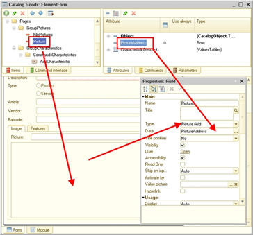
Fig. 502. Displaying picture on the form
// Example 1
// Attach a picture field to a picture address in the temporary
// storage. ImageAddress - the form attribute of the string type
PutFile(PictureAddress, OriginalName, SelectedName, True, UUID);
// Example 2
// Retrieve a picture address from an attribute of an infobase
// object
ImageFile =Object.ImageFile;
If No ImageFile.Blank() Then
ImageAddress = GetURL(ImageFile, "FileData");
Else
ImageAddress = "";
EndIf;Chapter 22. Event log
22.1. General information
To perform administrative tasks, it is often required to find out which events occurred at a particular point in time or what actions a particular user performed.
You can find this information in the event log. This log can record various events. Using the event log, the administrator can get the history of user operations.
The event log is not a part of a database and is not saved when exporting/importing an infobase.
1C:Enterprise logs the major actions by users who modify infobases, provide or deny access to data, perform routine operations, sign in, sign out, and so on.
Apart from interactive tools for log operations supported in Designer, log operations can also be defined programmatically.
This chapter covers programmatic tools for event log operations.
22.2. Specification management
You can manage the degree of detail of messages sent to the event log. For this, use the GetEventLogUsing and SetEventLogUsing methods.
// set up registration of all events in the log
Levels = New Array;
Levels.Add(EventLogLevel.Error);
Levels.Add(EventLogLevel.Information);
Levels.Add(EventLogLevel.Warning);
Levels.Add(EventLogLevel.Note);
SetEventLogUsing(Levels);22.3. Recording events
When you perform various operation, you need to record your actions for further analysis. You can use the event log for that. To record events in it, use the WriteLogEvent() global context method.
Note. Note. It is impossible to record system events in the event log using this method.
Custom event names can contain a dot in their names, thereby forming groups of custom events.
22.4. Event log management
22.4.1. General information
Recording of any event in the event log may be switched on or off. To do it, use the GetEventLogEventUse() and SetEventLogEventUse() global context methods and the EventLogEventUse object. The following example shows how to disable recording of the Performance error event ($PerformError$):
EventUse = New EventLogEventUse();
EventUse.Use = False;
SetEventLogEventUse("_$PerformError$_", EventUse);Please note that there are two events whose recording setup has additional options. They are the Access (_$Access$Access) and Access denied($Access$_AccessDenied) events. Operations with these events are described in detail below. However, when you set up recording of these events, please remember the following features:
-
Change recording settings in exclusive mode.
-
The change in recording settings made in the current session is guaranteed to be applied only after restarting all active sessions of this infobase.
Note. Note. Transaction-related events ($Transaction$.Begin, $Transaction$.Commit, and $Transaction$.Rollback) cannot be disabled by the SetEventLogEventUse() method.
22.4.2. Access event parameter setup
The Access event is used to record access instances of application users to certain data. To set up recording of the Access event, specify:
-
Whether event recording is required
-
List of metadata objects access to which must be recorded
-
List of metadata object fields whose reading must be recorded (access fields)
-
List of metadata object fields whose values must be recorded (record fields)
The general operational scheme looks like this (provided that the event is recorded). If one of selected access field is read during data operations (selected metadata object), record fields are recorded in the event log according to the specified rules. The fact of access is recorded at any access to the data made from the user session including access from 1C:Enterprise language code on the 1C:Enterprise server.
The amount of data to be recorded in the event log depends on the event recording setup:
| Use | Access fields | Registration fields | Result |
|---|---|---|---|
| Not specified | The event is not recorded | ||
| Specified | Not specified | Not specified | The event is not recorded |
| Specified | Specified | Not specified | The event is registered without specification |
| Specified | Specified | Specified | The event is recorded with specified record fields |
The event is generated only if data is successfully read.
Consider a specific example of parameter setup:
CatalogSetting = New EventLogAccessEventUseDescription();
// Specify the object access to which must be recorded
CatalogSetting.Object="Catalog.Individuals";
// Specify access fields
CatalogSetting.AccessFields.Add("PassportData");
CatalogSetting.AccessFields.Add("Children.BirthCertificate");
// Specify record fields
CatalogSetting.LoggedFields.Add("PassportData");
CatalogSetting.LoggedFields.Add("Children.ChildName");
FieldAlternatives = New Array();
FieldAlternatives.Add("Surname");
FieldAlternatives.Add("Name");
CatalogSetting.LoggedFields.Add(FieldAlternatives);
MetadataObjectSetting = New Array();
MetadataObjectSetting.Add(CatalogSetting);This example shows recording the access to items of the Individuals catalog.
At this, events of the event log are generated if the request to the data of the Individuals catalog includes:
-
PassportData field;
-
BirthCertificate field of the Children table;
If the data request does not include the mentioned fields, the access event to the data is not recorded in the event log.
After the system determines access to the controlled fields, data of the following fields in the Individuals catalog is recorded in the event log:
-
PassportData field.
-
ChildName field from the Children table
-
Surname or Name field Which of the fields will be logged depends on what data is included in the data query. Moreover, if all listed fields are used, the event log will contain the field with a smaller index (Surname in the example). If one field of the specified pair is used in the query, this field will be logged.
Let us review one more example of the Access event setup:
InformationRegisterSetting = New EventLogAccessEventUseDescription();
// Specify the object access to which must be recorded
InformationRegisterSetting.Object="InformationRegister.EmployeeWages";
// Specify access fields
InformationRegisterSetting.AccessFields.Add("Wage");
// Specify record fields
InformationRegisterSetting.LoggedFields.Add("Employee");
MetadataObjectSetting.Add(InformationRegisterSetting);In this example, the Access event will be recorded with the following components of the Data.Data field when the InformationRegister.EmployeeWages.Wage field is called:
-
If the InformationRegister.EmployeeWages.Employee field (and the Link field is set in the setting of record fields for the Individuals catalog, the Employee field refers to) is in the request result, the following will be recorded in the event log:
-
A value table with the CatalogIndividualsRef column containing reference values to objects of the Individuals catalog will be recorded to the Data field.
-
An array containing the InformationRegister.EmployeeWages string will be recorded to the Metadata field, meaning the name of the object that caused the access event logging.
-
The MetadataPresentation field will contain an array with the InformationRegister. Employee wages string, which is the metadata object presentation.
-
-
If the Ref field is not included in the record fields of the Individuals catalog, it will not be recorded in the query to the information register.
-
If the query gets data via the Catalog.Individuals type reference stored in the information register, fields that are obtained via a reference stored in the field of the Employee register will be recorded:
- If Name, Surname, and PassportData are obtained via the reference stored in the field of the Employee register, the PassportData and Surname fields will be recorded to the event log. See recording description for the Employees catalog in the previous example.
22.4.3. "Access denied" event parameter setup
The Access denied event is used to record occurrences of denied access to certain data for application users. To set up recording of the Access denied event, specify:
-
Whether event recording is required
-
List of metadata objects whose record fields must be recorded in case of denied access (denied access for other objects will be recorded without specification)
-
List of metadata object fields whose values must be recorded (record fields) in case of denied access.
The general operational scheme looks like this (provided that the event is recorded). In case of denied access during data operations (selected metadata object), record fields are recorded in the event log according to the specified rules.
The amount of data to be recorded in the event log depends on the event recording setup:
| Use | Registration fields | Result |
|---|---|---|
| Not specified | The event is not recorded | |
| Specified | Not specified | The event is recorded without specification (the Data field is not filled) |
| Specified | Specified | The event is recorded with specification of record fields in the Data field |
The event is generated in the following cases:
-
Upon access check of the entire data object:
-
Non-compliance with rights upon calls to methods and properties of the applied object from 1C:Enterprise language or from standard interface functions (forms, commands).
-
If access is denied when configuration rights are checked.
-
When the event emerges, the structure with the Right property containing the denied action will be transferred to the Data field of the log entry.
-
-
When data access restrictions are checked:
-
If terms of data access restriction are not complied with.
-
When the event emerges, the structure containing two properties will be transferred to the Data field of the log entry:
-
Action. Attempted action that resulted in denied access.
-
Data. Information about record fields (if specified).
-
Note. Note. When data is read to the temporary table, the Data.Data field of the event log is left blank.
Consider a specific example of parameter setup:
CatalogSetting = New EventLogAccessDeniedEventUseDescription();
// Specify the object access to which must be recorded
CatalogSetting.Object="Catalog.Individuals";
// Specify record fields
CatalogSetting.LoggedFields.Add("PassportData");
CatalogSetting.LoggedFields.Add("Children.ChildName");
FieldAlternatives = New Array();
FieldAlternatives.Add("Surname");
FieldAlternatives.Add("Name");
CatalogSetting.LoggedFields.Add(FieldAlternatives);If data access is breached, the Access denied event is recorded in the Read operation and the record field will be recorded according to the rules described in the record field of the Access event. The event is recorded for other actions (Change,Delete, and Add) but the data is not recorded.
22.5. Access right audit events.
Note. Note. Available only for CORP licenses.
When operating with the information system, it may be necessary to obtain information about who changed some administrative parameters of the system: roles, security profiles, user access rights, administrative settings, and so on. To record this information, 1C:Enterprise offers so-called "access right audit events" and a tool for managing generation of these events. Access right audit events include the following events:
-
$InfoBase$.RoleUpdate,
-
$User$.PermissionChange,
-
$InfoBase$.AdministrationParametersChange,
-
$InfoBase$.SecurityProfileChange.
Generation of these events is controlled as follows:
-
In client/server infobases: the Allow logging access right audit events checkbox in the server cluster settings or the AdministrationCluster.AllowAccessRightAuditEventsRecording property.
-
In file infobases: the EnableAccessRightAuditEventsWrite parameters of the conf.cfg file, which is located in the infobase directory.
Note that it takes a lot of time to prepare data for these events, so do not enable these events without any specific reason.
Let us take a closer look at audit events. Names of configuration objects in the event data are given in the same form as they are given in XML configuration dump files.
The $InfoBase$.RoleUpdate event occurs if, when saving the database configuration, it turns out that one or several Role objects are changed. Each modified object has its own logged event. Changes to the object are reflected in the event data. The data is represented by an object of the Structure type, which contains records with the following keys:
-
Rights. The value of the FixedStructure type, which contains configuration objects for which access rights are enabled or disabled. The structure contains the following properties:
-
AccessEnabled. Data of the FixedMap type that contains a list of configuration objects for which any access rights are set. In this case, a separate record is created for each object, where the Key field contains the name of the object for which access rights are enabled, and the Value field contains a fixed array that lists the added access rights.
-
AccessDisabled. The value of the property is similar to the value of the AccessEnabled property (by type and generation method), except that the property contains configuration objects for which any access rights are disabled.
-
-
Restrictions. The value of the FixedMap type that contains changes to data access restrictions by type of change and by configuration objects. The mapping contains the following properties:
-
Added. The value of the FixedMap type that contains added access restrictions. In this case, the Key field contains the configuration object name, and the Value field contains FixedMap which describes the additions made. In this mapping, the Key field contains FixedArray with field names (in terms of query language), including the <Other fields> internal field, and the Value field contains FixedArray, in which each item contains a restriction expression in the language of data access restriction queries.
-
Updated. The value of the FixedMap type that contains changed data access restrictions. The structure and filling method are similar to the Added property. Information about the data access restriction applied before the change was made is not provided.
-
Deleted. The value of the FixedMap type that contains deleted data access restrictions. The structure and filling method are similar to the Added property.
-
-
RestrictionTemplates. The value of the FixedMap type that contains information about added, changed, and deleted data access restriction templates. The structure contains the following properties:
-
Added. The value of the FixedArray type that contains a list of added restriction templates. Each template is described by objects of the FixedStructure type, which consists of the Name (template name) and TemplateText (restriction text in the language of data access restriction query).
-
Updated. The value of the FixedArray type that contains a list of changed restriction templates. The structure and filling method are similar to the Added property. Information about the data access restriction applied before the change was made is not provided.
-
Deleted. The value of the FixedArray type that contains a list of deleted restriction templates. The structure and filling method are similar to the Added property.
-
The $User$.PermissionChange event occurs when a change in access rights (the $InfoBase$.RoleUpdate event) causes the set of available database objects to change for some users. In this case, the $User$.PermissionChange event is logged, which contains the nature of changes in the event data. These events represent a value of the Structure type, which contains records with the following keys:
-
Users. The value of the FixedArray type, which contains the names of users whose sets of available objects changed.
-
DataSeparation. The value of the FixedStructure type. Describes the data area where you can find users for whom changes are recorded.
-
SecurityProfile. The name of the current security profile assigned to the infobase.
-
Rights, Restrictions, and RestrictionTemplates. The content is completely similar to similar records from the $InfoBase$.RoleUpdate event data.
The $InfoBase$.SecurityProfileChange event is generated when the settings of the security profile specified in the infobase parameters are changed. Such event will occur for each infobase that is controlled by the changed security profile. The security profile can be specified both as a value of the Security profile property and as a value of the Safe mode security profile property. These events represent a value of the FixedStructure type, which contains records with the following keys:
-
ClusterAdministrator. The name of the cluster administrator who made changes.
-
SecurityProfile. The value of the FixedStructure type, which contains new values for the changed security profile. Records in the structure have keys similar to the property names of the AdministrationSecurityProfile object.
The $InfoBase$.SecurityProfileChange event is logged deferred, using the InfoBaseSecurityProfileChange system background job.
When changing the infobase parameters in the server cluster, the $InfoBase$.AdministrationParametersChange event is generated for the infobase. The event is logged on behalf of the user who changed the infobase properties. These events contain new infobase parameters in the value of the FixedStructure type. Each property is described by a separate record. Records in the structure have keys similar to the property names of the AdministrationInfoBase object.
The $InfoBase$.AdministrationParametersChange event is logged deferred, using the InfoBaseAdministrationParametersChange system background job.
See also:
-
Dumping configurations to XML files.
-
Cluster parameters.
-
EnableAccessRightAuditEventsWrite parameter.
-
System background jobs.
22.6. Getting event log records
During application runtime, there might be some situations that require programmatic event log analysis, which includes getting events in the event log by some criteria (filter). To get event log entries programmatically, use the UnloadEventLog() global context method. You can programmatically get both event log entries of the infobase where 1C:Enterprise language code is performed and of any other infobase (even if other 1C:Enterprise instances operate this infobase) if the InputFileName parameter is specified for the UnloadEventLog method. Please remember that such reading is recommended only if event log files of another infobase are locally available for the 1C:Enterprise instance reading the log. If such access is unavailable, develop other methods to get the event log.
Note that getting event log entries might take a significant period of time. It is especially important to know when entries are obtained for an extended period or filtered. To avoid decreased system performance, the following measures are taken:
- In client/server mode, the number of sessions that simultaneously get event log data is limited to:
-
Not more than 4 simultaneous data queries from the event log to a single infobase
-
If a separated infobase is used, the additional limitation in 1 session of the data acquisition from event log is introduced for a data area.
In file mode, the amount of data to be obtained is unlimited.
-
By default, the event log is stored split by weeks. It is recommended that you split the event log in such intervals, so that the size of one .lpg event log file does not exceed 100 MB.
-
Indexing event log files. Indexing will allow you to filter data in the event log much faster. However, consider that improved filter performance can be achieved only when filtering by indexed fields of the event log. Index will be used if the following filter fields are applied:
-
Date;
-
Importance;
-
User;
-
Computer;
-
ApplicationName;
-
Event;
-
Data only if a reference type object serves as data
-
Metadata;
-
SessionDataSeparation.
When you perform event log operations, the data presentation string recorded in the log during event recording is displayed to the user only if it is possible to determine that this user has rights to view this presentation or the Administration right. If the user does not have the Administration right, and it is impossible to determine whether the user has rights to view the presentation, the data presentation is hidden from them. Therefore, the DataPresentation column is blank in the following cases:
-
In Designer: when viewing the event log if the user has no Administration right.
-
In 1C:Enterprise mode, when the UnloadEventLog() method is viewed and used, provided that all the following conditions are met:
-
The user is not granted the Administration right
-
Privileged mode is disabled
-
Relevant data presentation is unavailable for this link for any reason:
-
The data object is deleted
-
Not all independent separators that contain the data object are used in the session.
-
The user has insufficient rights to get the data object presentation.
-
-
Any of the following conditions is met for the respective metadata object:
-
The user is not granted the View right.
-
Data access is restricted for presentation fields.
-
-
To set the data selection conditions, use the Filter parameter of the UnloadEventLog() method. This parameter can contain either a single filter value set by the Structure object or an array of such structures. For more information about the structure format, see Syntax Assistant: Global context – Procedures and functions of event log operation – UnloadEventLog.
If the filter is set by a single item of the Structure type, all records that meet all the conditions specified in the structure will be included in the resulting dataset (combined by "AND"). If the filter is set up as an array, the resulting dataset includes the entries that meet at least one condition listed in the array elements (combined by "OR").
Consider the possibility to set up the filter by the Data field of the event log entry. A value array or values of the following types can serve as filter by this field: String,Number,Date,Ref,Structure for the Access,Access denied,Authentication,Authentication error,Add user,Change user and Remove user events.
A specific value, Structure or Array can be used as an item value of the structure passed to the Filter parameter. Below, you can see the way log entry data is checked to match filter parameters:
-
If a specific value is passed, values in this entry is compared with the filter value.
-
If a value array is passed, values of the event log entry data are compared with all values of the array passed to the filter. The condition is considered met if the value specified in the log entry matches even a single value of the passed array.
-
If a structure is passed as a value, the condition is considered met if all structure elements passed as a filter item match the event log entry data.
For more details, see below.
-
A structure is located in the Data field of the event log entry, and there is also a structure in the Data filter field. In this case, the entry meets the condition if the Data field of the log entry contains all keys from the respective filter field and values for these keys match.
-
The Data field of the log event entry contains a value table. A structure is specified in the Data filter field. In this case, the entry meets the condition if names of the value table columns match the names of filter structure keys, and there are rows where values of relevant columns are equal to values of the structure from the filter.
-
The Data field of the event log entry contains a value of the Structure, Array, or ValueTable type. An array is specified in the Data filter field. In this case, the entry meets the condition if at least one value of the array passed as the filter value is found in the log entry data.
-
The Data field of the event log entry contains a value (not a structure, not an array, not a value table). An array is specified in the Data filter field. In this case, the entry meets the condition if the value of the log entry matches at least one value from the passed array.
-
The Data field of the log entry contains an item with a value of the ValueTable type. The Data filter field contains an item with a value of the Array type. Filter keys match. In this case, the event log entry meets the condition if at least one cell in the value table matches at least one value of the passed array.
-
The Data field of the log entry contains a value of the Structure,Array, or ValueTable type. The Data filter field contains a value of the Structure or Array type. In this case, the log entry meets the condition if an entry that meets the condition under paragraphs 1 and 5 is found in the nested data. However, if a structure is specified in the filter, items in the structure or value table columns in the event log entry matching the items of this structure are searched only at a certain nesting level that matches the nesting level in the filter. Therefore, specific values and values from arrays are searched for at all levels in the filter, and items of the filter structure are searched for only at a certain level.
If the generated table of values in the field Data of the event log entry has columns with the similar name, these columns are combined into one. The number of rows in this table is increased so that the resulting column contains all unique values from columns of the same name. Values specified in other columns are duplicated in the created rows.
Consider an example below. The application contains a query that returns a table with the following columns:
-
CatalogRef.Goods,
-
CatalogRef.Goods,
-
String.
The following conversion is completed upon event log entry generation:
-
The first two columns are merged into one.
-
A new row is generated for each row where the Goods.Ref and Products.Ref values do not match.
-
Rows differ by the value of the merged column where reference values are located. The other column values will be the same.
Initial table:
| Ref | Ref | Item |
|---|---|---|
| Hot dogs | Pepper | 16-AB-1675 |
Resulting table:
| Ref | Item |
|---|---|
| Hot dogs | 16-AB-1675 |
| Pepper | 16-AB-1675 |
Consider the following examples that demonstrate how filters behave when event log entries are obtained:
Example 1:
-
Value of the Data field in the event log entry for the Authentication event:
-
Type: Structure:
- Key: OSUser, value: Smith
-
-
Value of the Data filter field of the UnloadEventLog() method:
-
Type: Structure:
- Key: OSUser, value: Smith
-
-
Result: the record matches the filter
Example 2:
-
Value of the Data field of the event log entry for the Access event:
-
Type: Structure:
- Key: Data, value: ValueTable:
-
| Last name | City | Phone |
|---|---|---|
| Collins | New York | 111-22-33 |
| Smith | Seattle | 222-33-44 |
-
Value of the Data filter field of the UnloadEventLog() method:
-
Type: Array:
-
Item 1: Structure:
- Key: OSUser, value: Smith
-
Item 2: Structure:
-
Key: Data, value: Structure
-
Key: LastName, value: Smith
-
Key: City, value: Seattle
-
-
-
-
Result: the record matches the filter because a match is found when comparing item 2 of the filter array with the record data (line 2). The event log entry has the value table with the Name and City columns, and both column values match respective values in the filter structure.
Example 3:
-
Value of the Data field in the event log entry for the Add user event:
-
Type: Structure:
-
Key: Roles, value: Array:
-
Value 1: Roles.Administrator;
-
Value 2: Roles.WarehouseSupervisor;
-
Value 3: Roles.Seller
-
-
-
-
Value of the Data filter field of the UnloadEventLog() method:
-
Type: Structure:
- Key: Roles, value: Roles.WarehouseSupervisor
-
-
Result: the record matches the filter because the Data field contains the Roles item, and one of the item values is Roles.WarehouseSupervisor.
Example 4:
-
Value of the Data field in the event log entry for the Add user event:
-
Type: Structure:
-
Key: Roles, value: Array:
-
Value 1: Roles.Administrator;
-
Value 2: Roles.WarehouseSupervisor;
-
Value 3: Roles.Seller
-
-
-
-
Value of the Data filter field of the UnloadEventLog() method:
-
Type: Structure:
-
Key: Roles, value: Array:
-
Value 1: Roles.Manager
-
Value 2: Roles.Seller
-
-
-
-
Result: the record matches the filter because the Data field contains the Roles item, and one of the item values is specified in the filter array (Roles.Seller).
Example 5:
-
Value of the Data field of the event log entry for the Access event:
-
Type: Structure:
- Key: Data, value: ValueTable:
-
| Last name | City |
|---|---|
| Collins | New York |
| Smith | Seattle |
-
Value of the Data filter field of the UnloadEventLog() method:
-
Type: Array:
-
Type Structure:
- Key: Data, value: New York
-
-
-
Result: the record matches the filter because the searched New York value is found in one of the cells of the value table located in the Data property of the Data field in the event log record.
For the Metadata field of the event log entry where the metadata array is stored in the event, the entry matches the filter provided that at least one array element from the Metadata filter field matches at least one element of the log entry array.
22.7. Additional methods
To facilitate interactive generation of event log filters, use the GetEventLogFilterValues() method. You can use this method to get available filter values for the following filter parameters: User, Computer, ApplicationName, Event, Metadata, ServerName, Port, and SyncPort. This way, if you need to set up the filter for the event log event, you can first get the list of events that are actually present in this log and then select from the obtained list.
Use the EventLogEventPresentation() method to generate presentations of event log events in the platform interface language.
If you need to copy an event log fragment with a specific filter, use the CopyEventLog() method.
To control the event log splitting period, use the GetEventLogDataStorageSplitPeriod() and SetEventLogDataStorageSplitPeriod() methods. To set a separation period, use the EventLogDataStorageSplitPeriod system enumeration. You can set the event log splitting period only for the .lgf event log (sequential format).
To get the time interval for which the event log stores data, use the GetEventLogPeriod() method. Storage dates will be located in corresponding properties of the Range type returned by the method.
To truncate the event log size, use the TruncateEventLog() method. Both event log formats support truncation.
Chapter 23. Cryptographic feature
23.1. General information
If you use 1C:Enterprise in automation systems, you might need to check whether a certain document stored in the system has not been changed. For example, a document containing the contract text is attached to the Contract database object. You may also need to ensure transfer of any authorized information or organize confirmation of a certain document within the system. In some situations, you might need to ensure transfer of information via open channels so that nobody can intercept and read it (encrypt the data).
For such situations, the cryptographic feature is implemented in 1C:Enterprise. It is based on asymmetric encryption and uses public and private key pairs.
Note. Important. The cryptographic feature of 1C:Enterprise does not contain implementation of cryptographic algorithms as they are. It provides a set of objects for interaction with external third-party cryptography modules.
Public key is used for transfer via open channels. Private key cannot be distributed and must be protected at the highest level (secret key).
You need to know public keys of receivers to encrypt data. To decrypt data, you need to have their private key, which is the pair for the public key specified for encryption. To generate a digital signature, you need a private key. To check a signature, you need the public key of the signer. The public key is frequently included in the signature.
Symmetric encryption is used alongside with asymmetric encryption to encrypt the data. Symmetric encryption is an encryption method when the same key is used both for encryption and decryption. Symmetric encryption features are described further in the chapter.
When you apply the cryptographic feature, consider the place where it is applied. It is important since the cryptographic procedures considerably differ in the client application and on the server. The server uses so called synchronous cryptographic methods. The client application, on the other hand, uses asynchronous methods.
To apply this feature in web client, you need to install the cryptography extension. In web client, a special query is executed to authorize access of the user to some operations. In particular, access to the file system and private key.
23.2. Basic concepts
Some terms will be used to describe the features.
Electronic digital signature (hereinafter referred to as EDS) is a sequence of data obtained as a result of cryptographic conversion of source data using a private EDS key. It helps to confirm integrity and stability of this data as well as its authorship provided that the public EDS key and its certificate are used. Digital signature can be attached or not attached. If the digital signature is attached, it is stored together with signed data in one file. If the digital signature is not attached, the data and the signature are stored in different files.
Center for certification of the electronic digital signature (hereinafter referred to as Certificate authority) is a legal entity or a special division of the legal entity that is authorized to certify that a certain public EDS key belongs to a certain user. Certificates required to perform cryptographic operations are issued by the certificate authority.
Public key certificate or certificate is an electronic document that includes a public key and information about its owner verified with an EDS by the certificate authority.
Key container is a store that contains a private key and also a public key (paired to this private one). Access to the container content is protected by a password or some other means.
Key certificate owner is a person for whom the certificate authority creates a public key certificate and who owns the respective private (secret) key.
Cryptography module is a library of functions where cryptographic algorithms are directly implemented or used to access cryptographic features.
Trusted timestamp is accurate information in electronic form about the date and time of signing an electronic document with a digital signature. A trusted timestamp is created and verified by a trusted third party, the certificate authority, or an information system operator. This timestamp is obtained when an electronic document is signed with a digital signature in the established order using software and/or hardware.
23.3. General application procedure of cryptographic features
23.3.1. General information
Cryptographic features are mainly used for:
-
Data encryption/decryption
-
Data signature/signature check
When you use the CryptoManager object, it is not recommended that you get several certificate storages with the same characteristics since modification of one storage might lead to different behavior of the other storage depending on the used cryptography modules.
If you use cryptographic features and need to explicitly specify the algorithm that will be used during encryption, hashing, or signature generation, specify these algorithms not as an abbreviation but as an object ID (OID). This is due to the fact that the same algorithm can be described differently by different service owners, but it will still be an algorithm with a specific unique OID. The SHA-256 signature generation algorithm has OID 2.16.840.1.101.3.4.2.1. A cryptographic algorithm with a public RSA key has OID 1.2.840.113549.1.1.1. For more information on OID, go to https://oidref.com/.
The following sections will describe how to use different cryptographic feature options in more detail.
23.3.2. Encryption/decryption
The general encryption/decryption procedure looks as follows:
-
Create an appropriate object to access the cryptographic feature: CryptoManager.
-
Select a certificate that will be the public key of the recipient:CryptoCertificate. This certificate will be used to encrypt the data.
-
The required file or binary data is encrypted using the Encrypt() methods of the generated object of the CryptoManager type.
For encryption, both symmetric and asymmetric encryption are used. First, the system generates a key for symmetric encryption. After that, this key encrypts the required data. The symmetric encryption key is encrypted by an asymmetric key. A data batch suitable for transfer via open channels is generated from three components: encrypted data, encrypted key for symmetrical encryption, and a list of recipients. The data batch is generated according to the CMS specification (based on PKCS#7).
-
The encrypted data is ready for transfer via open channels.
-
The reversed procedure is done when the encrypted data is received.
-
Create an appropriate object to access the cryptographic feature. The cryptography module related to the object must support processing of algorithms used for data encryption.
-
The received data is decrypted using the Decrypt() method of the object generated for access to the cryptographic feature.
The encrypted key for symmetric encryption is extracted from the incoming batch during decryption. The key is further decrypted using the private key paired with the public key used for encryption. After that, the obtained key is used in the symmetric algorithm to decrypt the array of obtained data. This way, if the receiving party ("from" of the symmetrical encryption) does not have any private key, data decryption by the symmetric algorithm is impossible.
23.3.3. Signature/signature verification
The general procedure for signature creation/check looks as follows:
-
Create an appropriate object to access the cryptographic feature: CryptoManager.
-
Select an appropriate certificate related to the private key of the signer: CryptoCertificate. This certificate will be used for EDS generation.
-
Select an EDS option using the IncludeDataInSignature property of the created CryptoManager object:
-
If True, an attached EDS will be created.
-
If False, a non-attached EDS will be created (default value).
The selected EDS influences further actions.
- An EDS of the required file or binary data is generated using the Sign() methods of the generated object of the CryptoManager type.
When you generate a signature, remember that the hash of data to be signed is generated first. After that, the resulting hash is signed. This reduces the time of the data signing procedure.
Due to that, it is recommended that you explicitly specify the algorithms to be used for both hash calculation (the HashAlgorithm property) and signing (the SignAlgorithm property). If the recipient does not support the used algorithms (hashing and signature), it will be impossible to check the signature.
To explicitly specify applied algorithms, use the GetCryptoModuleInformation() method of the cryptographic manager. The method returns the CryptoModuleInformation object whose SignAlgorithms and HashAlgorithms properties contain the list of algorithms supported by the used cryptography module. Specify the data in the properties of the CryptoModuleInformation object in the properties of the cryptographic manager.
The information about used algorithms will be in the signature, so you do not have to pass it together with the signed data.
-
Signed data is passed to the recipient. It includes either one file (attached EDS) or two files (non-attached EDS: a data file and an EDS file).
-
The reversed procedure is done once the signed data is received.
-
Create an appropriate object to access the cryptographic feature. The cryptography module related to the object must support algorithms used for EDS generation.
-
The electronic signature is checked using the VerifySignature() method of the object created for access to the cryptographic feature. If the cryptography module used to check the signature does not support the algorithm used for hash calculation and data signing, signature check is impossible and an error is displayed.
1C:Enterprise allows you to generate digital signatures in CAdES (with different subtypes) and CMS formats (obsolete). To specify the digital signature type, use the SignatureType parameter of the Sign() method. CAdES-BES signatures are used by default. Each following format (except for CMS) is an extension of the previous format. For example, CAdES-T is an extension of CAdES-BES, CAdES-C is an extension of CAdES-T, and so on. The following signature formats are available:
-
CAdES-BES (CAdESBES). Basic digital signature of the CAdES standard (default value).
-
CAdES-T (CAdEST). Digital signature with a trusted timestamp.
-
CAdES-C (CAdESC). Digital signature with complete validation data references.
-
CAdES-X Long Type 2 (CAdESXLongType2). Long-term extended signature with several extensions.
-
CAdES-A v3 (CAdESAv3). Archival digital signature.
-
CMS (CMS). Obsolete digital signature format.
If you need to archive a signed document, do the following:
-
Sign the document with a CAdES-A signature used for archive storage. If this has not been done, enhance the existing signature using the EnhanceSignature() method.
-
If the document is signed with a CMS signature, you cannot enhance it. Sign the document again with a CAdES-A signature.
-
After the document has been archived, periodically add an archive timestamp to the existing signature (once a year is recommended) using the AddArchiveTimestamp() method. For the platform to get a trusted timestamp, set timestamp servers. To do this, use the TimestampServersAddresses property of the cryptography manager. For example, 1C Company server https://1stdss.1c.ru/TSP/tsp.srf or any available server can be a timestamp server.
When you verify a digital signature, you might need to verify the selected timestamps. To do this, use the VerifyTimestamp() method.
23.4. Public key certificate
As mentioned above, a public key certificate (or simply certificate) is an electronic document of a certain format that contains a public key, identification information of the key owner, and some official information that is digitally signed by a certificate authority. In the 1C:Enterprise system, certificate is displayed as a CryptoCertificate object. In this section, the term "certificate" and the CryptoCertificate object name will be used as synonyms, unless the context (or explicit usage) suggests otherwise. Let's take a closer look at this object.
A certificate can be created from a file, from binary data, or obtained from a certificate store. Depending on where a certificate is created (on the client or server), the set of constructors and methods that are used to create certificates slightly differs. If the code is running on the server, the certificate constructor from the New CryptoCertificate(<File name>) file or the New CryptoCertificate(BinaryDataObject) file if the certificate is created from binary data. If the code is running on the client, an "empty" New CryptoCertificate() object is created first. Then this object is filled with data using the BeginInitialization() or InitializeAsync() methods. The method parameters can be a file name, binary data, or a stream (in any variant). To obtain a certificate from a certificate store, there is a CryptoCertificateStore object and a rich set of methods of this object for obtaining one or several certificates.
You can export the certificate to a disk drive using the Unload()/UnloadAsync()/BeginUnload() methods of the CryptoCertificate object.
Now let's look at what information about a public key certificate the CryptoCertificate object allows you to get. All information is displayed as object properties. To understand the property values, it is highly desirable to understand what object IDs (OID) are and which ID values correspond to what. For the source of information on OID, see General information. Some IDs and their descriptions are given in Syntax Assistant, in the description of the CertificateExtensions property.
The Version property defines the version of the X.509 standard, which describes the public key infrastructure and defines the format and content of the properties of the public key certificate. For more information about the certificate format, see RFC 2459 (https://datatracker.ietf.org/doc/html/rfc2459) and RFC 5280 (https://datatracker.ietf.org/doc/html/rfc5280). The StartDate and EndDate properties determine the validity period of the certificate. The SerialNumber property contains a unique certificate number within the certificate authority that issued this certificate. This certificate authority is specified in the Publisher property. The certificate holder is described by the Subject property. The description of the certification authority and the certificate owner follows the same structure: the parameters describing the certification authority and the subject are contained in properties of a fixed structure. They include both mnemonic IDs (such as C, N, OU) and object IDs (such as OID2_5_4_10).
The UseToSign and UseToEncrypt properties describe what this certificate can be used for. The certificate contains a public key value (the PublicKey property) and the description of the public key algorithm in this certificate (the PublicKeyAlgorithm property). The algorithm is defined in terms of object identifiers (OID). The value of the public key is stored in the PublicKey property as binary data. Since the certificate is signed by the certificate authority, the signature information is also contained in the certificate: the SignatureValue property contains a digital signature of the certificate in binary data format, and the SignatureAlgorithm property contains a description of the digital signature algorithm in terms of object IDs (OID). The Thumbprint property contains the SHA-1 hash of the entire certificate (as binary data). The CertificateExtensions property contains Map which contains the certificate extensions. Each extension is identified by its own object ID (the Key field of the map item), and the extension value in a usable form is located in the Value field of the map item. The CertificateExtensionsAsRawData certificate property contains the same information as the CertificateExtensions property, but the extension values are presented in their "raw" form, exactly as they appear in the certificate, without any decoding or interpretation.
The StartUniversalDateOfPrivateKey and UniversalDateOfPrivateKeyExpiration properties contain information about the validity period of the private key related to this certificate. Note that the private key is not represented in any way in the 1C:Enterprise object model. The private key must be held only by the subject for whom this key is generated by the certificate authority. As a rule, the private key is stored in a special format container. This container can store not only the private key, but also a paired public key certificate. The container is protected by a password, which is known only to the responsible person of the private key subject.
To check the certificate for applicability and correctness, use the CheckCertificate()/BeginCheckingCertificate()/CheckCertificateAsync() methods of the cryptography manager. The method receives the certificate to be checked, the check mode or modes, and the check date. The check date is an optional parameter that allows you to check the certificate not at the current time, but at a different point in time. If the check date is specified, checking the certificate, building a chain of certificates, searching for lists of revoked certificates, and determining the certificate status will be performed based on this date. The date is specified in UTC format, not in local time. The certificate check mode is transferred either as a single value or a set of values (as an array):
-
IgnoreTimeValidity. Do not check the certificate validity period.
-
IgnoreSignatureValidity. Do not check the validity of the certificate's digital signature (certificate authority signature).
-
IgnoreCertificateRevocationStatus. Do not check the certificate for revocation against the list of revoked certificates.
-
AllowTestCertificates. The certificate being checked can be a test certificate (a self-signed root certificate that can be used to check and sign the driver package or to test-sign the driver on Windows).
If any violation (inconsistency) is detected during the check, an exception will be thrown. If the certificate is valid, the method will be completed successfully (but without return codes).
In conclusion, here is an example of displaying some information about all certificates of root certification centers on a 1C:Enterprise server cluster computer:
CryptoManager = New CryptoManager("", "", 80);
Storage = CryptoManager.GetCertificateStore(CryptoCertificateStoreType.RootCertificates);
StoreCertificates = Storage.GetAll();
For Each Certificate In
StoreCertificates Do
Message = "";
SubjectName = "";
If Not
Certificate.Subject.Property("CN", SubjectName) Then
If Not Certificate.Subject.Property("O", SubjectName) Then
SubjectName = "??";
EndIf;
EndIf;
Valid = "";
If CurrentSessionDate() > Certificate.EndDate Then
Valid = "expired (" + Format(Certificate.EndDate, "DF=dd.MM.yyyy") + ")";
Else
Valid = Format(Certificate.StartDate, "DF=dd.MM.yyyy") + " - " + Format(Certificate.EndDate, "DF=dd.MM.yyyy")
EndIf;
Message = Message + "Certificate """ + SubjectName + """ - ";
Message = Message + " key algorithm: " + Certificate.PublicKeyAlgorithm;
Message = Message + " signature algorithm: " + Certificate.SignatureAlgorithm;
Message = Message + " valid: " + Valid;
Message(Message);
EndDo;23.5. Operation of cryptography modules
To interact with cryptography modules on Windows, use Microsoft CryptoAPI. On Linux or macOS, use CryptoPRO CSP interface.
Supported add-ins:
- CryptoPro, the cryptographic data protection tool. To use the tool, set the CryptoprotectionModuleType parameter of the CryptoManager object wizard to 80.
23.6. Application examples
23.6.1. General information
This section provides implementation examples for some standard tasks when using the cryptographic feature.
23.6.2. Creating an object for access to the cryptographic feature
Creating an object for access to the cryptographic feature is a basic procedure whose absence prevents any further procedures with the cryptographic feature.
CryptoManager = New CryptoManager("", "", 80);In this example, the module is created for Russian cryptography modules (the CryptoModuleType parameter is set to 80).
To determine location of the CryptoPro CSP module on Linux or macOS, use the following algorithm:
-
If the CryptoModulePath parameter is specified in the cryptography manager constructor, the system attempts to use the module specified as the parameter value.
-
If the CryptoModulePath parameter is not specified in the cryptography manager constructor, the system attempts to find the cryptography module in computer directories that are specified using the CryptoAPILibraryLocation parameter of the conf.cfg file.
-
If the CryptoAPILibraryLocation parameter is missing in the conf.cfg file, the system attempts to find the CryptoPRO module using standard module location paths.
If cryptography module parameters are unknown, you can use a simple method for creating a cryptography manager:
ForInitialization = New CryptoManager();
Promise = ForInitialization.InitializeAsync(CryptoInteractiveModeUse.Use);
CryptoManager = Await
Promise;23.6.3. Getting a certificate list
The list of certificates is generated from selected certificate storages for further operations with this list.
Async Function
GetCertificateList(CryptoManagerType, TypeArray, CheckEndDate)
CertificateList = New Array;
CryptoManager = New CryptoManager("", "", CryptoManagerType);
For Each StoreType In TypeArray Do
// Get certificates for each type of certificate storage
Store = Await CryptoManager.GetCertificateStoreAsync(StoreType);
// Select all certificates
StoreCertificates = Await Store.GetAllAsync();
CurrentDate = CurrentDate();
For Each Certificate In StoreCertificates Do
// Check that this is not a certificate expiration date
If CheckEndDate And Certificate.EndDate < CurrentDate Then
Continue;
EndIf;
CertificateList.Add(Certificate);
EndDo;
EndDo;
Return CertificateList;
EndFunction
&AtClient
Async Procedure
ExecuteCommand(Command)
StoreTypes = New Array;
StoreTypes.Add(CryptoCertificateStoreType.PersonalCertificates);
StoreTypes.Add(CryptoCertificateStoreType.RecipientCertificates);
List = Await GetCertificateList(80, StoreTypes, True);
// …
EndProcedure23.6.4. File encryption
The interactively selected file is encrypted and the encrypted file is interactively recorded to the hard drive of the client computer.
For demonstration purposes, the first certificate from the list of all certificates installed on the computer is always used for the encryption procedure.
&AtServer
Function EncryptAtServer(DataAddress, CertificatesData)
// Generate certificates based on binary data of certificates from
the client
Certificates = New Array();
For Each CertificateData In CertificatesData Do
Certificates.Add(New CryptoCertificate(CertificateData));
EndDo;
CryptoManager = New CryptoManager("", "", 80);
// Get the file for encryption from the temporary storage
Data = GetFromTempStorage(DataAddress);
If TypeOf(Data) <> Type("BinaryData") Then
Return False;
EndIf;
// Encrypt the binary data
EncryptedBinaryData = CryptoManager.Encrypt(Data, Certificates);
// Save to the temporary storage
DataAddress = PutToTempStorage(EncryptedBinaryData);
Return True;
EndFunction
&AtClient
Async Procedure
ExecuteCommand(Command)
StoredFile = Await PutFileToServerAsync(, , , New PutFilesDialogParameters);
If StoredFile = Undefined Then
Return;
EndIf;
Address = StoredFile.Address;
CertificatesTypes = New Array;
CertificatesTypes.Add(CryptoCertificateStoreType.PersonalCertificates);
List = Await GetCertificateList(80, CertificateTypes, True);
// The first certificate in the list is always used in the example
// In practice, it might not work, so
// you need to select a certificate by other criteria
Certificates = New Array;
Certificates.Add(Await List[0].UnloadAsync());
// Encrypt the file
EncryptionResult = EncryptAtServer(Address, Certificates);
If Not EncryptionResult Then
Return;
EndIf;
// Save the encrypted file interactively to the hard drive
GetFileFromServerAsync(Address, StoredFile.FileRef.File.FullName + ".signed", New GetFilesDialogParameters);
EndProcedure23.6.5. File decryption
Decryption of the selected file is attempted. You need to implement the GetAccessPassword() method that returns the password value to access the private key.
Note. Note. When you use the Decrypt() method, an exception is thrown only after decryption attempts using all available certificates have failed, not after the first error.
&AtClient
Async Procedure
FileDecryption()
// Select an encrypted file
StoredFile = Await PutFileToServerAsync(, , , New PutFilesDialogParameters);
If StoredFile = Undefined Then
Return;
EndIf;
Data = GetFromTempStorage(StoredFile.Address);
// Decrypt the file
CryptoManager = New CryptoManager("", "", 80);
CryptoManager.PrivateKeyAccessPassword = GetAccessPassword();
DecryptedData = Await CryptoManager.DecryptAsync(Data);
Address = PutToTempStorage(DecryptedData);
GetFileFromServerAsync(Address, , New GetFilesDialogParameters);
EndProcedure23.6.6. EDS generation
Sign the selected file with EDS. The signature option is defined by the AttachedSignature parameter of the SignFile() method. If the AttachedSignature parameter is set to True, an attached EDS is generated. The EDS with data will be saved to a file with the same name as the selected file name and the .sign extension. If the AttachedSignature parameter is set to False, a non-attached EDS is generated. The EDS is always saved to the signature.sign file. You need to implement the following functions:
-
GetAccessPassword(). Returns the password value to access the private key.
-
GetCertificateList(). Returns an array of certificates that can be used to generate an EDS.
&AtClient
Async Function
SignFile(AttachedSignature)
// Select a file to sign
StoredFile = Await PutFileToServerAsync(, , , New PutFilesDialogParameters);
If StoredFile = Undefined Then
Return Undefined;
EndIf;
Data = GetFromTempStorage(StoredFile.Address);
// Generate a signature file
CertificatesTypes = New Array;
CertificatesTypes.Add(CryptoCertificateStoreType.PersonalCertificates);
List = Await GetCertificateList(80, CertificateTypes, True);
// The first certificate in the list is always used in the example
// In practice, it might not work, so
// you need to select a certificate by other criteria
Certificate = List[0];
Data = GetFromTempStorage(StoredFile.Address);
CryptoManager = New CryptoManager("", "", 80);
CryptoManager.PrivateKeyAccessPassword = GetAccessPassword();
FileForSignature = StoredFile.FileRef.File;
CryptoManager.IncludeDataInSignature = AttachedSignature;
If AttachedSignature Then
FileName = Await CryptoManager.SignAsync(Data, FileForSignature.Path
+ FileForSignature.BaseName + ".sign", Certificate);
Else
FileName = Await CryptoManager.SignAsync(Data, FileForSignature.Path
+ "signature.sign", Certificate);
EndIf;
EndFunction23.6.7. EDS checking
The feature checks whether the EDS is certified for a file. First, it checks whether the file is the EDS file with data. If the file without an attached EDS is passed, the non-attached EDS is expected to be in the signature.sign file. In this case, the EDS file is expected to be in the same directory as the signed file. The file signed by the attached EDS is passed to the SignedData variable. This data is not used in the example.
&AtClient
Async Function
VerifyFileSignature()
// Select a signed file
FileToCheck = Await PutFileToServerAsync(, , , New PutFilesDialogParameters);
If FileToCheck = Undefined Then
Return Undefined;
EndIf;
FileData = GetFromTempStorage(FileToCheck.Address);
CryptoManager = New CryptoManager("", "", 80);
IsAttachedSignature = Await
CryptoManager.CheckForDataInSignatureAsync(FileData);
If IsAttachedSignature Then
Certificate = Await CryptoManager.VerifySignatureAsync(FileData);
SignedData = Await
CryptoManager.GetDataFromSignatureAsync(FileData);
Else
CheckedSignature = Await PutFileToServerAsync(, , , FileToCheck.FileRef.File.Path + "signature.sign");
If CheckedSignature = Undefined Then
Return Undefined;
EndIf;
Signature = GetFromTempStorage(CheckedSignature.Address);
Certificate = Await CryptoManager.VerifySignatureAsync(FileData, Signature);
EndIf;
EndFunction23.6.8. EDS enhancement
The function enhances the non-attached EDS by changing it to the type that contains a trusted timestamp. It is considered that the signature is stored in a file with the same name and the same .sign extension. The enhanced signature will be saved to a file with the .extsign extension. In this example, it is proposed to select not a signature file, but a signed file. The function will generate names of the signature file and enhanced signature file.
&AtClient
Async Procedure ExecuteCommand(Command)
// Select a
signed file
StoredFile = Await PutFileToServerAsync(, , , New PutFilesDialogParameters);
If StoredFile
= Undefined Then
Return;
EndIf;
SignatureFileName
= StrReplace(StoredFile.FileRef.File.FullName, StoredFile.FileRef.Extension, ".sign");
EnhancedSignatureFileName
= StrReplace(StoredFile.FileRef.File.FullName, StoredFile.FileRef.Extension, ".extsign");
StoredSignature
= Await PutFileToServerAsync( , , , SignatureFileName);
If StoredSignature = Undefined Then
Return;
EndIf;
Signature = GetFromTempStorage(StoredSignature.Address);
CryptoManager
= New CryptoManager("", "", 80);
// Set trusted
timestamp server addresses
Addresses = New Array;
Addresses.Add("http://testca2012.cryptopro.ru/tsp/tsp.srf");
CryptoManager.TimestampServersAddresses
= Addresses;
// Enhance the
file signature
Await
CryptoManager.EnhanceSignatureAsync(Signature.EnhancedSignatureFileName, CryptoSignatureType.CAdESAv3);
EndProcedure23.6.9. Adding an archive timestamp
If a signed document is archived, you need to periodically add archive timestamps to the signature of this document. The function demonstrates this operation for all non-attached EDS files located in a directory. Let us assume that the EDS file is a file with an arbitrary name and the .sign extension. The EDS file with the added archive timestamp is saved to the same file.
&AtClient
Async Procedure ExecuteCommand(Command)
CryptoManager
= New CryptoManager("", "", 80);
// Set trusted
timestamp server addresses
Addresses = New Array;
Addresses.Add("https://1stdss.1c.ru/TSP/tsp.srf");
CryptoManager.TimestampServersAddresses
= Addresses;
// Select all
signature files
SourceDirectory
= "c:/temp/";
SignatureFiles
= Await FindFilesAsync(SourceDirectory, "*.sign", False);
For Each
SignatureFile In SignatureFiles Do
NewSignature
= Await CryptoManager.AddArchiveTimestampAsync(SignatureFile.FullName);
// save the
signature back to the file
Await
NewSignature.WriteAsync(SignatureFile.FullName);
EndDo;
EndProcedure23.6.10. Getting information on signatures
The example shows how to receive information on signatures the file is signed with. The example shows automatic signature type identification. The non-attached signature uses the signature storing algorithm described in the EDS generation and verification example.
&AtClient
Async Procedure GetInformationOnSignatures(Command)
// Select a
signed file
FileToCheck = Await PutFileToServerAsync(, , , New PutFilesDialogParameters);
If FileToCheck
= Undefined Then
Return;
EndIf;
FileData = GetFromTempStorage(FileToCheck.Address);
CryptoManager
= New CryptoManager("", "", 80);
IsAttachedSignature
= Await CryptoManager.CheckForDataInSignatureAsync(FileData);
If IsAttachedSignature Then
SignatureContainer
= Await CryptoManager.GetCryptoSignaturesContainerAsync(FileData);
Else
CheckedSignature
= Await PutFileToServerAsync(, , , FileToCheck.FileRef.File.Path + "signature.sign");
If CheckedSignature = Undefined Then
Return;
EndIf;
TimestampData
= GetFromTempStorage(CheckedSignature.Address);
SignatureContainer
= Await CryptoManager.GetCryptoSignaturesContainerAsync(TimestampData);
EndIf;
For each Signature In
SignatureContainer.Signatures Do
String = "";
String = "Index: " + Signature.Index;
String = String + " Data: " + ?(Signature.Data= Undefined, "missing", "present");
String = String + " SignatureType: " + Signature.SignatureType;
String = String + " HashAlgorithm: " + Signature.HashAlgorithm;
String = String + " SignAlgorithm: " + Signature.SignAlgorithm;
Message(String);
EndDo;
EndProcedure23.7. Asynchronous operation of the cryptographic feature
The asynchronous cryptography mode has some distinct features:
-
It is available only from the client application. Use the synchronous mode one the server.
-
To use cryptography in web client, you must install the cryptography extension.
Let us look at the cryptographic feature behavior in asynchronous mode. As an example, consider the acquisition procedure of the certificate list from a certain type of certificate storage.
Note. Note. The example below is not complete. It is used to demonstrate the asynchronous operation of cryptographic tools.
&AtClient
Async Procedure GetList(Command)
Cryptography = New CryptoManager;
Await
Cryptography.InitializeAsync("", "", 80);
CertificatesStore
= Await
Cryptography.GetCertificateStoreAsync(CryptoCertificateStoreType.PersonalCertificates);
CertificatesArray
= Await CertificatesStore.GetAllAsync();
For Each
Certificate In CertificatesArray Do
Message("Serial
certificate number = " + Certificate.SerialNumber);
EndDo;
EndProcedureThis example shows all cryptography features in asynchronous mode. The example shows that the code in 1C:Enterprise language is almost identical to the one used in synchronous mode.
Chapter 24. Data separation feature
24.1. General information
Data separation feature is a specific feature that allows you to divide all stored data and the operation of the application into individual parts. If the Data separation property of a common attribute (see Common attributes) is set to Separate, the data separation mode is enabled. In addition:
-
The behaviour of configuration objects included in a common attribute (hereinafter referred to as a separator) changes.
-
The current separator value and a flag of the separator use is determined for each separator in the infobase.
-
Configuration objects included in such common attribute are called separated configuration objects.
-
Configurations with such common attributes are considered to be separated configurations.
-
Infobases with a separated configuration are called separated infobases.
-
Infobase data available for selected separator values and data of shared configuration objects are called data area.
In all procedures of database entry reading 1C:Enterprise automatically selects only the entries where values of used separators coincide with current values of separators. When the data are recorded, the platform checks that the recorded data contain values of used separators equal to current values of separators or equal to default values for relevant types. If it is not true, an exception is thrown.
Example:
// The object is initially recorded with the value of separator
Subscriber = 1
Object = LinkToObject.GetObject();
// Change the separator value in the current session
SessionParameters.SubscriberValue = 2;
// The object will not be recorded and an exception will be thrown
Object.Write();If the recorded data contain values of separators equal to default values for relevant types, values of used separators in the current session will be recorded into separators of the object. For separators that are not used in the current session:
-
When reading data, filter by these separators is not performed.
-
When modifying data, values included in the data to write are used.
The separator may contain the following configuration objects:
-
Constants
-
Catalogs
-
Documents
-
Sequences
-
Document journals
-
Charts of characteristic types
-
Charts of accounts
-
Charts of calculation types
-
Business processes
-
Tasks
-
Information registers
-
Accumulation registers
-
Accounting registers
-
Calculation registers
-
Exchange plans
-
Scheduled jobs
-
Infobase users (see User separation).
You should remember that sequences and document journals are separated objects only if they include separated configuration objects. Components of separators for objects included into the sequence or the document journal should be identical.
The separator in the Independent and shared mode can be used in data access restrictions (see Data access restriction).
Type of the separator may not be union.
If the general attribute is used as the separator, it will have several additional properties affecting the behavior of the system and the behavior of configuration objects included into the separator also changes. More details of these properties will be considered in next sections.
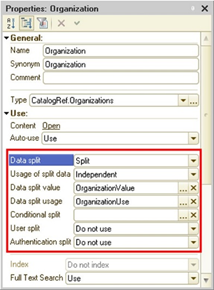
Fig. 503. Common attribute with separation
Note. Warning! If you use the separator with the type String the language of regional infobase settings for operation of Microsoft SQL Server cannot be changed.
Note. Warning! Data separation is not supported for DBMS Microsoft SQL Server 2000, IBM DB2 9.1 as well as for DBMS IBM DB2 of other versions if string comparison in the DBMS is case-sensitive(parameterCOLLATION_SEQUENCE is not equal to UCA500R1_LROOT_AN_CX_EX_FX_HX_NX_S2).
24.2. Common attribute properties
24.2.1. Separated data use
The Separated data use property determines the option for use of the separated data in configuration object if the separator is not used in 1C:Enterprise mode:
- Independently. No call to separated objects is allowed, except for exchange plans (see Exchange plans) if the separator is not used in the current infobase session. At this, the separator is unavailable in the object-based model, in the query language, in the format of upload into XML and XDTO as well as in data access restrictions. When the separated data are recorded, the system automatically fills values of the general attributes with the values set up in the current session. In this mode configuration extensions may be added to the data of native configuration objects and generate native objects storing the data in the infobase.
You can use this mode when the application uses only data of a single data area.
Note. Warning! In this mode, object links in the database can be similar for objects written in different data areas.
- Independent and shared. Operations with separated objects are allowed no matter whether the separator is used in the session. A data area determined by values of used separators will be available for this mode. At this, the separator is available in the object-based model, in the query language, in the format of upload to XML and XDTO as well as in data access restrictions. In this mode, you cannot create predefined items for objects included in such separator. If the session does not use all separators that include the object, operation of this objects will be less effective. This mode does not support any data extension.
You can use this mode when the application mostly operates with data of a single data area (for example, when entering documents) and, in some modes, can use data of several or all areas (for example, to obtain consolidated statements).
Note. Warning! In this mode, object links in the database cannot be similar for different objects written in different data areas.
24.2.2. Separator value and usage flag
The Data separation value property determines a session parameter that stores a separator value set in the current session. The type of the session parameters should exactly match the type of the separator.
The Data separation use property determines a session parameter (the Boolean type) that manages the use of the separator. If the value of the specified session parameter is True, it means that the separator is used in this session.
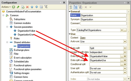
Fig. 504. Session parameters and a common attribute
You can change values of session parameters during the system operation if the user on whose behalf the session operates has rights to change necessary session parameters. 1C:Enterprise does not warrant integrity of the application data once session parameters are changed.
When the value of the session parameters referred to by at least one separator is changed from the 1C:Enterprise language, the following actions are needed:
-
Object cache is cleared.
-
Repeated values are removed (see Return value reuse) on the client side and the server side.
You can specify a separator value in 1C:Enterprise 8 startup command-line using theZ parameter or in the connection string using the Zn parameter.
24.2.3. User separation
The User separation property determines what part of the user list will be available depending on whether this separator is used or not. If the property is set to Do not use, a single user list is used for any separator values. Separation of users is used for the program access to the user list as well as in the Designer when the user list is edited.
You may use the following table (related to one separator) to determine whether the user is available in the session or not:
| The separator is used in the session | The separator is not used in the session | |
| The value is set for the user | Available if separator values are equal | Available |
| The value is not set for the user | Unavailable | Available |
When the user is edited, you can specify values for all separators set in the configuration and not only for those whoseUser separation property is set to Separate. Values of separators specified in properties of the infobase user will be used to set up values of separators when the session of this user starts. Values of separators in the command string or the connection string has a higher priority than values specified in user properties if the user has rights to change relative session parameters.
24.2.4. Authentication separation
The Authentication separation property is used to manage the option to generate users with the same name for different data areas. If the property is set to Do not use, username uniqueness is monitored for all data areas. If the property is set to Separate, you can generate users with the same name in different data areas. For example, you may generate several users Administrator that will be different only by values of separators (including for the non-set value of the separator).
If there is the separator Subscriber (type Number) and the value of the property Separation of authentication for it is set up in the value Separate there is the option to generate the following user list:
| Username | Subscriber separator value |
|---|---|
| Administrator | Not specified |
| Administrator | 1634 |
| Administrator | 2245 |
| Administrator | 1245 |
If the Authentication separation property value for this separator is set to Do not use, you cannot generate such list. Usernames must be unique, for example:
| Username | Subscriber separator value |
|---|---|
| IBAdministrator | Not specified |
| 1634Administrator | 1634 |
| 2245Administrator | 2245 |
| 1245Administrator | 1245 |
24.2.5. Configuration extension separation
The Configuration extension separation property is used to manage the option for separation of extensions between various data areas.
If the property is set to Separate, only extensions that have been applied with the same separator value as the user has will be available for the user. If the property is set to Do not use, values of such separator will not be considered when extensions are applied and availability of extensions for the current user is determined.
When the value of this property for the separator is changed you should consider the following features:
-
When the property is set from Separate to Do not use, this separator stops being considered when availability of extensions that have already been downloaded is determined.
-
When the property is set from Do not use to Separate, all existing extensions become available in the data area that matches the special separator value describing the disconnected separator.
It is recommended to disable the extension separation for the separator that is in the Independent and shared mode.
See also:
-
Configuration extension (see Configuration extension).
-
Separator value (see Separator value and usage flag).
24.2.6. Conditional separation
24.2.6.1. General description
Conditional separation is needed when it is suggested to use the application both in separated and shared options. For example, the application may be used for autonomous operation. In this case, separators are not used but they are provided in the application and it may be used to operate some amount of subscribers not related to each other (with the individual data set in the infobase). You can implement this behavior using conditional separation. Separation will be disabled in standalone mode, but enabled in separated mode.
Conditional separation is made as follows:
-
For a separator (or an object included in the separator), you can set an object that stores the separation state for this separator.
-
When you change the value of this object, you can enable or disable the separation for this separator for all object (if conditional separation is set for the separator itself) or for selected objects (if conditional separation is set for the object included in the separator).
-
If the separator is conditionally disabled, the separator value will be the default value of a specific separator type.
Note. Note. For each separator the value of conditional separation may not be directly or indirectly depend on the value of the separator itself.
The recursive management of conditional separation is available when conditional separation is set for the separator used to determine conditional separation of another separator, and so on. In this case, determination of conditional separation will start from the separator which value is not conditionally separated (but it affects other objects involved into conditional separation) and then using the bound separators until conditional separation is not determined for the separation which condition does not affect any separator anymore. It is impossible to generate looped conditional separation.
Conditional separation can enable or disable the separation as follows:
-
For all objects included into the separator. In this case, use the Conditional separation separator property.
-
For individual objects included into the separator. For this you should use the column Conditional separation in the window for editing components of the separator.
-
By combination of properties described above.
When you arrange conditional separation, you should consider the following features:
-
The following items may be used as the object storing the value of conditional separation:
-
The constant of the Boolean type that is not included in the separator, for which conditional separation is set up.
-
The attribute of the Boolean type in the reference configuration object that must meet the following conditions:
-
It is not included in the separator, for which conditional separation is set up.
-
It must be used as a type of another separator, and there must be only one separator of this type.
-
-
-
When the system is started, values of session parameters storing the flag of use and values of separators is initially set up according to starting command-line parameters or values specified for the infobase user. For more information on setting separator values at startup, see Setting separator values at startup.
-
If common attribute separation is conditionally disabled, then:
-
When the data is read and written, the current values of session parameters responsible for the value and the use of the separator are ignored. The following values are used:
-
Usage flag. True (the separator is used).
-
Separator value. The default value for a separator type.
-
-
When infobase users are read and written, the current values of session parameters responsible for the value and the use of the separator are ignored. The following values are used:
-
Usage flag. False (the separator is not used).
-
Separator value: Not used.
-
-
-
If the value determining conditional separation is not read or ambiguous, exception will be given.
-
If the separator used in conditional separation of the other separator is not used the other separator is also considered to be unused.
-
If all separators are disabled in the session (using conditional separation), actions with the infobase that are unavailable if at least one separator is used become available.
If conditional separation is set up both in a common attribute property (the Conditional separation common attribute property) and using the Conditional separation column of the common attribute, one of the following values will be used as a separator value:
-
The current separator value (set to the respective session parameter) if the separation is conditionally enabled both by an object (an attribute or a constant) specified in the respective column of the common attribute and by the object (an attribute or a constant) specified in the separator property.
-
The default value for a separator type if conditional separation is enabled by any method.
Note. Note. Conditional separation is not used in Designer. Attributes are supposed to be conditionally enabled in a Designer session constantly.
24.2.6.2. Conditional separation set up in common attribute properties
24.2.6.2.1. Using a constant
The separator may be completely disabled using a constant. The constant must have the Boolean type and cannot be separated by an attribute.
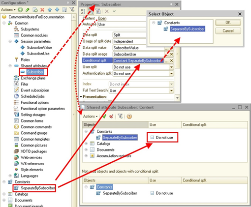
Fig. 505. Conditional separation using the constant
Note. Attention! When 1C:Enterprise is initially started (once conditional separation is added) the value of the constant will be False and separation will be disabled.
Let us take a look at this case in more detail.
There is the general attribute Subscriber with the type Number. This attribute includes the directory Products containing the following:
| Code | Description | Subscriber |
|---|---|---|
| 1 | Sandals | 0 |
| 2 | Boots | 1 |
| 3 | Felt boots | 2 |
| 4 | Trainers | 1 |
| 5 | Flip-flops | 0 |
Conditional separation managed by the constant SeparationForSubscribers is used for the general attribute. If the constant value is False, the separator is disabled (separation is disabled). If the constant value is True, the separator is active (separation is enabled).
Thus, the following situations may be found out:
- The value of the separator Subscriber is 1, the separator is used, the value of the constant SeparationForSubscribers is True. In this session, separation is conditionally enabled (for the Subscriber separator). In this situation the following items are available in the directory:
| Code | Description | Subscriber |
|---|---|---|
| 2 | Boots | 1 |
| 4 | Trainers | 1 |
- The value of the constant SeparationForSubscribers is False. In this session, separation is conditionally disabled (for the Subscriber separator). In this situation, regardless the value of session parameters SubscriberUse and SubscriberValue, the following items are available in the directory:
| Code | Description | Subscriber |
|---|---|---|
| 1 | Sandals | 0 |
| 5 | Flip-flops | 0 |
24.2.6.2.2. Using an object attribute
A more complex option of conditional separation management is used if the data of one separator is used for conditional separation of the other separator. Then, the behavior of the separator describing another data area might be different within various data areas.
For example, there is a set of configuration objects that describe master data: the Banks, Currencies, and VAT rates catalogs. You should implement the following option:
-
You can keep accounting for various company groups in the infobase.
-
Each company group consists of organizations.
-
Master data objects can be either common for all company group organizations or specific for each organization.
Implementation of such design will require the following configuration objects:
-
CompanyGroups catalog with the CommonMasterData attribute of the Boolean type
-
Companies catalog
-
Banks catalog
-
Currencies catalog
-
VATRates catalog
-
CompanyGroups separator of the CatalogRef.CompanyGroups type
-
Organization separator of the CatalogRef.Companies type This separator includes only objects describing the master data:
-
Banks catalog
-
Currencies catalog
-
VATRates catalog
-
The CompanyGroup separator includes all considered catalogs (except the CompanyGroups catalog) as we need its own list of organizations and master data for each company group.
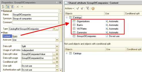
Fig. 506. "CompanyGroup" separator
The Organization separator includes only the Banks, Currencies, and VATRates catalogs. These catalogs are master data, and they require two usage options:
-
For each organization of the selected company group
-
For all organizations of the selected company group.
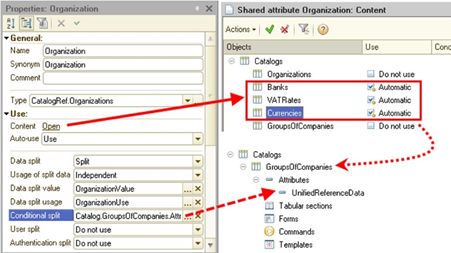
Fig. 507. "Organization" separator
The CompanyGroups catalog is not included in the Organization separator as it is required by the conditional separation rules (see General description).
Now you can specify a value of the CommonMasterData attribute for each value of the CompanyGroup separator (an item of the CompanyGroups catalog):
-
If the attribute is set to False, conditional separation is disabled and any value of the Organization separator receives a common value set of the Banks, Currencies, and VATRates catalogs (within one value of the CompanyGroup separator).
-
If the attribute is set to True, conditional separation is enabled and any value of the Organization separator receives its own values set of the Banks, Currencies, and VATRates catalogs (within one value of the CompanyGroup separator).
When you change the CommonMasterData property value, the separator is enabled or disabled for the Organization separator.
Let us suppose that the CompanyGroups catalog contains the following information:
| Description | CommonMasterData | Ref |
|---|---|---|
| Progress | False | GK1 |
| Trading house | True | GK2 |
The Organizations catalog contains the following information (two records for each value of the CompanyGroup separator):
| Description | CompanyGroup | Ref |
|---|---|---|
| Component base | GK1 | OR1 |
| World of air conditioners | GK1 | OR2 |
| Construction trade | GK2 | OR3 |
| Light | GK2 | OR4 |
The Banks catalog will have the following information:
| Description | CompanyGroup | Organization |
|---|---|---|
| AlfaBank | GK1 | Blank link |
| SberBank | GK1 | OR1 |
| VTB | GK1 | OR2 |
| Avangard | GK2 | OR1 |
| Uralsib | GK2 | OR2 |
Now let us take a look at the example of what data will be available in each case.
Example 1:
The CommonMasterData attribute for the Progress item is set to False.
It means that the separation for the Banks catalog is disabled. It means that the catalog does not depend on a value of the Organization separator. In this case, the value equal to the default value for the separator type will be written to the item of the Banks catalog (for the Organization separator). In our case, such value is a blank link (as the type of the Organization separator is a link to the catalog). So, if the CompanyGroup separator is set to CG1, the Banks catalog list will display only AlfaBank.
Example 2:
The CommonMasterData attribute for the Progress item is set to True.
It means that separation for the Banks catalog is enabled. It means that the catalog depends both on the value of the CompanyGroup separator and on the value of the Organization separator.
That is why, the list of banks for the Progress company group and for the World of air conditioners company will include only the VTB bank.
When you change the value of the CommonMasterData attribute (and separator values) when the system is running, you can receive the list content for the Banks catalog (according to the conditional separation rules).
24.2.6.3. Conditional separation set for objects (in the Components property)
You can set conditional separation for each configuration object included in the separator. In this case, separation will be disabled only for objects for which conditional separation is set up.
You can manage conditional separation using a constant or a configuration object attribute (see General description).
Let us take a look at the example of such separation.
For example, several subscribers may do accounting in the same infobase, and you may do accounting within each subscriber on behalf of several partners. At this, the situation may occur when all partners operate the same list of warehouses and the situation may occur when you may generate its own list of warehouses for each company.
Implementation of such design will require the following configuration objects:
-
Subscribers catalog with the IndividualWarehousesList attribute of the Boolean type
-
Companies catalog
-
Warehouses catalog
-
Subscribers separator of the CatalogRef.Subscribers type
-
Organization separator of the CatalogRef.Companies type
To arrange the considered design:
-
Exclude the Companies catalog from the Organization separator.
-
For the Warehouses catalog (included in the Organization separator), set up conditional separation using the IndividualWarehousesList attribute of the Subscribers catalog.
Let us suppose that the Subscribers catalog has the following records:
| Description | IndividualWarehousesList |
|---|---|
| Subscriber 3453 | True |
| Subscriber 4617 | False |
If you log in on behalf of subscriber No. 3453, you can keep an individual list of warehouses for each organization as the IndividualWarehousesList attribute is set to True. It means that the separation of the Warehouses catalog in the Organization separator is enabled.
At the same time, when you log in to the system on behalf of subscriber No. 4617, the list of warehouses will be the same for all organizations. The WarehousesSeparateList attribute is set to False. The separation of the Warehouses catalog in the Organization separator is disabled.
24.2.6.4. Conditional separation features in distributed systems
Usage of conditional separation in the distributed system has some features. These features can be divided into "logical" and "technical".
The "technical" features include the inability to arbitrarily change the state of the object controlling the conditional separation in a separated session, if this object is part of a separated exchange plan. It is related to the specifics of automatic object change registration by separated exchange plans (see Exchange plans). At automatically registration of changes it is possible to change the object that controls the conditional separation either in a unshared session or when the current state of the object is False. That is, it is only possible to enable conditional separation, and there is no possibility to turn it off (in automatic mode).
The "logical" feature is that the change in the state of conditional separation in the main node of the distributed infobase has a significant impact on the state and behavior of the entire distributed information system. This change can affect one data area if the conditional separation is controlled by an attribute of the object that serves as the type of the other separator (see Using an object attribute). Also, changing the conditional separation state can affect the entire infobase if the conditional separation is used to switch between two application modes (see Using a constant).
Thus, in the first case (example with a regulatory and legislation data) when changing the conditional separation in the peripheral database users, "disappears" the regulatory and legislation data. Therefore, only the data domain administrator or the person with sufficient authority to accept such a change should have access to the change to the attribute that controls the conditional separation.
The second example (changing the mode of the application) will have an impact on the whole infobase. In peripheral infobases, users might "lose" all their data due to changing the separator value and so on. It is obvious that only the administrator of the entire infobase (or the person authorized for such actions) can perform such a critical change, while other users may not even be able to read this attribute (or constants).
24.3. Defining whether actions or data sets are available
When the system uses multiple separators to determine whether a certain action with a particular object is available, apply the following rule:
-
For each separator that separates the required object, determine whether you can perform an action as if the system has only one separator. In this case, consider the separation mode: independent or independent and shared.
-
The result for all separators is summed up "by AND".
The following sections will discuss how to perform an action on an object for a single separator (unless otherwise explicitly described). Then is needed to apply this rule to get the final action if the object is part of multiple separators.
For example, there are two independent separators in the system: Subscriber and Organization. There are two catalogs: Products and Counterparties. Each directory is separated by both separators.
Example 1:
You need to determine whether you can receive the list of items if the Subscriber separator is used and the Organization separator is not used.
As both of the separators are independent, the separator must be used to obtain the catalog list. It means that:
-
For the Subscriber separator, it is possible to get the list of items because the separator is used. The result is equal to True.
-
For the Organization separator, the item list cannot be obtained because the separator is not used. The result is equal to False.
-
So, in a session with such separator settings, the catalog list view will be (True AND False = False) unavailable.
Example 2:
You need to determine whether you can obtain a list of counterparties if both of the separators are used.
As both of the separators are independent, the separator must be used to obtain the catalog list. It means that:
-
For the Subscriber separator, the list of counterparties can be obtained as the separator is used. The result is equal to True.
-
For the Organization separator, the list of counterparties can be obtained as the separator is used. The result is equal to True.
-
So, in a session with such separator settings, the catalog list view will be (True AND True = True) available.
Example 3:
You need to determine what values for the User column the GetEventLogFilterValues() method will return. Two separators have been created in the system. The first separator is used in the current session, and the second one is not used. It means that:
-
For the first separator, the method returns only users who are registered in the event log for separator values equal to the value in the current session.
-
For the second separator, the method returns all users (see Filters).
-
So, in a session with the specified separator state, the method will return only users that will be the intersection of the lists for the first and the second separators (the AND operation).
24.4. Setting separator values at startup
24.4.1. General information
When starting up 1C:Enterprise, you might need to specify a separator value directly in the startup command line. For example, to authenticate when authentication separation is selected.
If one or more separator values are not specified in the command line, missing separators are taken from separators specified for the current user. If the same separator is specified for both the user and the command line and their values do not match, the use and value of the separator will be set from the command line if the user of the infobase has the right to set session parameters that store the use and value of the separator. Otherwise, the user will not be authenticated.
When debugging a client running from Designer, you can specify separators in the startup setup dialog box in Designer. When specifying a user that must perform the startup, user selection is available. The list is limited to the specified separator values that separate authentication.
In the process of user authentication information database, the values of session parameters that are referenced properties Using separator and Separator value of the metadata object Overall attribute are set to the values specified for the user. By the time any code is executed in the 1C:Enterprise language (including the session module), the values of these session parameters will be set, and the event handler SessionParametersSetting will not be called when they are accessed.
It should be remembered that the definition of the separator value by its passed ID is performed without taking into account the use of other separators. That is, the definition of the separator value does not depend on the order of setting the values (and flag of usage) of other separators. If the system cannot uniquely determine the separator value by its ID (for example, there are two dictionary elements with the same code), an exception will be thrown.
If the usage flag and the separator value (see below) that are specified in the start line are different from the values that are specified for the user, then:
-
If the user has rights to change session parameters that store the value and the flag of separator usage, these values are set from the start command line.
-
If the user does not have such rights, authentication fails.
24.4.2. Client application command line
To specify separator values, use the Z command-line parameter.
Parameter syntax:
/Z
"[<Flag>][<Value>][,[<Flag>][<Value>]]"Description:
Each <Flag><Value> pair is responsible for setting one separator. Separators cannot be skipped. The order of the <Flag><Value> pairs corresponds to the order of separators in the configuration window. If the order of common attributes changes (for example, the list of common attributes is sorted), change the location of values in the Z parameter. The <Flag><Value> pairs are separated by commas (",").Parameters:
<Flag>
Indicates that this separator is used. It can take the following values: "+" (by default) and "-". If the separator value is preceded by "+" or nothing is specified, the specified value will be written to the session parameter that stores the common attribute value. At the same time, the session parameter that stores the use of the common attribute will be set to True.
If the separator value is preceded by "-", the separator is not used in this session. The session parameter that is responsible for using the separator will be set to False. However, if the value is specified, it will be written to the session parameter that stores the common attribute value.
<Value>
Specifies the value to be set in the session parameter that stores the value of the appropriate separator. The separator value is set in text form and has the following format (depending on the separator type):
-
For the Boolean type, 0 (False) or 1 (True) are specified.
-
For the Digit type, a digit in canonical form is specified.
-
For the Date type, a date is specified in yyyymmddhhiiss format, where:
-
yyyy is a year (4 digits).
-
mm is a month number (2 digits).
-
dd is a day number (2 digits).
-
hh is an hour number (2 digits).
-
ii is a minute number (2 digits).
-
ss is seconds (2 digits).
-
When setting the parameter, specify all date components, so that the parameter value consists of 14 digits.
-
For the String type, the text itself is specified.
-
For reference types, the text representation of the standard attribute Code or Number is specified. Codes and numbers must be unique among all values of the corresponding object of configuration. It is not allowed to use directories with code length equal to 0, and documents with numerators. If the link is a type of the shared attribute which is the separator, the code or the number of the predefined element is not allowed, if the predefined elements in this infobase have not yet been created for the object forming the separator type.
If the "+" or "-" character must be located at the beginning of the parameter value, it is doubled. If the text line describing the separator value must contain a comma ",", this character is doubled.
If the value specified in the command-line parameter can correspond to different types of values at the same time, (for example, "1" can denote the True value, number "1", catalog code "1", and document number "1"), the conversion rule is determined based on the type of the appropriate separator.
If only a flag ("+" or "-") is specified in the command line and no value is specified, the default value of the appropriate type is used as a separator value.
Example:
/Z
" 0,+001,+,---3"In this example:
-
The first separator is not used, but its value is specified: 0.
-
The second separator is used and its value is equal to 001.
-
The third separator is used and its value will be the default value for the type specified as a common attribute type.
-
The fourth separator is not used but its value will be -3.
24.4.3. Web client or thin client connected via a web server
There are two ways you can specify separator values when starting a web client (or thin client connected via a web server): in the address (command) line by the Z parameter and in the default.vrd file.
24.4.3.1. Using Z parameter
You can specify separator values in the address line using the Z parameter. The parameter format for the web client is similar to the command line for running the client application.
Example:
http://localhost/infobase?Z="
FirstSeparator,+"Characters which cannot be used in URL (RFC 1738 and https://datatracker.ietf.org/doc/html/rfc1738.html) are transformed into UTF-8 and encrypted in accordance with section 2.2. URL Character Encoding Issues of the RFC 1738 standard using the "%" character and two hexadecimal characters.
24.4.3.2. In the default.vrd file
It is possible to configure access to the infobase in such a way that the specific values of the separators will be set by the address of the infobase, and not by using command-line parameter Z or the connection string to the infobase. To do this, configure the <zones> element of the default.vrd file accordingly.
It is also possible to prevent the values of objects associated with the data separation mechanism from being changed if the infobase is accessed using a web client or a thin client connected via a web server (secure session). Such an opportunity should be used if you need a guarantee that access to an infobase over the Internet will not be able to access another data area.
24.4.4. External connection and connection string
In the connection string and when the external connection is started, the following Zn parameter is used. The format of the parameter is similar to the command-line for running the client application.
Example:
Srvr=localhost;Ref=Demo82Srv;Zn="
FirstSeparator,+,---3"Also, it is possible to specify this parameter in the default.vrd file (in the connection string with infobase) when publishing to a web server.
There is another way to set the separators value in the default.vrd file (see In the default.).
24.5. Safe data separation mode
When using various scheduled operations performed within sessions with unused separator values, you can execute the application program code, but you cannot check its "reliability". "Reliability" means that the operation is performed within the specified restrictions. For example, the called code should only work within the separators values that the caller has set for it, without attempting to navigate to other data areas. Such an attempt may lead to unauthorized access to the data of the "foreign" data area.
To prevent attempts to change the values of separators (and, as a consequence, the data area in which the program code works), it is possible to establish a safe mode of data separation. To do this, use the SetDataSeparationSafeMode() method. You can use this method for a separator similar to specifying a safe="true" attribute value for the zone item of the default.vrd file for this separator. If secure data separation mode is enabled by using the default.vrd file, then it is impossible to disable it using the method SetDataSeparationSafeMode().
You cannot perform the following actions in the safe data separation mode:
-
Disable a separator if the separation is not conditionally disabled.
-
Change the used separator value if the separation is not conditionally disabled.
-
Modify objects managing the conditional separation:
-
Specified for the separator itself
-
Specified for objects included in the separator
-
You can set the safe data separation mode for each separator individually. The number of times when you enable and disable the safe data separation mode must be the same. However, if the safe data separation mode is enabled within a procedure or a function (once or more) but it is not disabled, the system will automatically disable it as many times as there are incomplete calls in the procedure or the function you leave.
If the safe data separation mode is enabled for the selected separator in a procedure or a function more times than it is disabled, an exception will be thrown.
This feature can be implemented as follows (the system has the independent Subscriber separator):
For Each SeparatorValue
From SeparatorsValuesList Do
// go to the
required area
SetSeparatorValue(SeparatorValue);
// set the secure mode of data separation
SetDataSeparationSafeMode("Subscriber", True);
// call the
necessary program code
Process the
data of area();
// turn off
secure mode of data separation
SetDataSeparationSafeMode("Subscriber", False);
EndDoYou can check the status of the safe data separation mode using the DataSeparationSafeMode() method.
24.6. Deleting data areas
When operating in the system, you might need to remove an unnecessary data area. For example, a subscriber ceases to use the services (each subscriber uses one data area), or the company group is reorganized (each company in the group uses its own area).
It is also possible that separators are removed from the system. However, if separators include configuration objects with predefined data, you cannot remove the separator until the predefined data is deleted (see Predefined data).
To delete a data area, use the EraseInfoBaseData() global context method or the /EraseData command-line parameter of Designer batch run mode. For 1C:Enterprise language method, an area to delete is determined by session parameter values that define the separator values in the session where the method is called from:
-
If no separator is used in the current session, all infobase data will be deleted. After deletion, the state of the infobase becomes the same as after creating a new, blank infobase and loading the configuration into it.
-
If at least one separator is used in the current session, the fully separated data of the current data area is deleted. If two or more separators are used simultaneously (if they store their values and conditional separation data in the same configuration objects), the EraseInfoBaseData() method will consider a configuration object as being part of the current area if it is separated by at least one of the said separators using the same configuration objects to store their parameters. Deleting the data area causes the area to be in the same state as after the first setting of current set of values for the used separators before executing operations with data.
Note. Tip. Immediately after executing the method, it is recommended to change the values of separators that define the data area.
To call the method, the user must have theAdministration right and the ability to obtain exclusive access to the infobase. Set the exclusive access by explicitly calling the SetExclusiveMode() global context method. If this is not done, an attempt to set exclusive mode will be made in the method. In case of an error in obtaining exclusive access, the method execution fails.
When deleting a data area using Designer batch run mode, an area to delete is determined by the /Z startup command-line parameter (see Setting separator values at startup). If some separators are missing, the area is determined similarly to the call of the EraseInfoBaseData() method (see above). The system tries to automatically obtain exclusive access to the infobase. In case of an error in obtaining exclusive access, the execution of the batch mode of running the Configurator fails.
The following data will be deleted during the deletion:
-
Data from tables related to configuration objects included in separators (including predefined data and data added by extensions).
-
Settings storages.
-
User work history.
-
Infobase users list.
-
Infobase time zone. If no independent separators are defined in the configuration, the parameter value becomes undefined. Otherwise, the value is deleted.
-
If no separator is used in the session, all saved password policies will be deleted, and the password policy settings for the infobase will be reset to their default values.
-
In version 8.3.2 or earlier compatibility mode, predefined data receives values defined in Designer or default values. When the compatibility mode is disabled, predefined data will be created when you access them for the first time.
-
Attribute values of the ThisNode item of exchange plans will be set to default values.
-
Shared constant values receive default values, and separated constant values are removed.
-
Infobase registration data in the collaboration service.
-
For the data history, the method behavior depends on the session in which the method is called:
-
Shared infobase or no separators are used in the session:
-
All existing versions are deleted from the entire infobase.
-
All data history settings are deleted. Versioning settings are aligned with the settings in the metadata.
-
-
The session uses both independent and shared separators:
-
The data history for completely separated data is deleted.
-
Versioning settings and metadata history are not deleted.
-
-
In the session, only independent separators are used:
-
The data history for completely separated data is deleted.
-
Data history usage settings for the current separators are deleted.
-
Metadata history for the current separators is deleted.
-
-
24.7. System object behavior specifics
For details on the behavior of system objects when using separators, see System object specifics in the data separation mode.
Chapter 25. Data history
25.1. General information
Data history is a special feature which allows you to store configuration object data ordered by a timeline in the database. We will also use data versioning as an equal term. The database stores a version. It includes data existed in the object at the moment of change as well as metadata state at the moment of change. The feature allows you to configure data history storage for the entire object and better manage the feature for each attribute including tables. The arbitrary data, which content is determined by the developer, can be added to each version when versioning the data. The functionality also allows the actions which shall take place after the data version is actually saved to a database table (version post-processing). Post-processing can be used when a version saving fact starts one or several actions. The fact that the action shall be performed after the successful saving of both the object and its next version is the principal difference.
You can enable and disable the history from Designer and using 1C:Enterprise language. Thus, it becomes possible to include change history storage only for the data that is needed by specific users, without the need to change the configuration.
In addition to storing the actual changes, the data history feature allows you to perform the following operations:
-
Write data version for the supported object.
-
Write additional data absent in the actual versioned object data.
-
Get data of a certain version including the additional data if it is set.
-
Delete data of a particular version.
-
Get the difference between two data history items.
-
Other useful features.
Data history is supported for the following objects:
-
General attributes.
-
Constants.
-
Exchange plans.
-
Catalogs.
-
Documents.
-
Charts of characteristic types.
-
Charts of accounts.
-
Charts of calculation types.
-
Business processes.
-
Tasks.
-
Information registers.
Dealing with data history is regulated by access rights and logged in the event log.
Data history is not transferred through mechanisms of distributed infobase.
25.2. Mechanism structure
Data history is stored in special tables of the same infobase for which versioning is set. In addition to the data itself, the data history also stores metadata of previous versions of versioned objects. Version of metadata of the object is created at the time of change of the object's metadata. The moment of creation of the metadata version has nothing to do with changing the data of the versioned object. The data history does not store the types of attributes, but only the actual values of these attributes. It should also be remembered that from the point of view of the system, the following pairs of actions are the same:
-
Enable attribute versioning and create a new attribute.
-
Disable attribute versioning and delete the attribute.
In addition to storing the changed versioned object data, versioning allows specifying a special comment and additional data for each version. This data can be used upon subsequent analysis of changed data.
The process of forming a version consists of several steps:
-
System records an object change. This occurs either automatically or by calling a method in the program interface. Information about the object change is transferred to a special queue (version queue). At this point, you can add an arbitrary data required for subsequent operations to the versioned data (the WriteDataHistory.AddAdditionalData() versioned object method).
-
Data is transferred from the version queue to the database tables that actually store the version data. This operation is performed with the help of the DataHistory.UpdateHistory() method. You can update the data history asynchronously, for example, by using a scheduled job. The process is similar to updating the full-text search index. In other words, the data version becomes "real" only after it is moved from the queue of versions to the tables of history storing. In this case, several consecutive changes to the data object (no matter how these changes are made) are recorded separately and transferred separately. So, all changes to data objects are recorded in the data history, regardless of the frequency of history updates and the number of consecutive changes to one object. Each processed data version will be transferred to a special queue of versions requiring processing after the version saving (post-processing queue). The necessity of such transfer is defined by the WriteDataHistory.ProcessAfterWriting versioned object property.
-
Post-processing queue processing begins after the version queue processing completion. This processing can be performed by the DataHistory.UpdateHistory() method and the special DataHistory.ExecuteAfterWriteVersionsProcessing() method. The processing itself shall be performed in the AfterWriteDataHistoryVersionsProcessing() handlers of the versioned object manager modules.
-
After the version post-processing completion, delete the version from the post-processing queue with the help of the DataHistory.DeleteFromAfterWriteVersionsProcessing() method. If you do not do it, this version will be constantly transferred to the AfterWriteDataHistoryVersionsProcessing() event handlers.
-
To clear the post-processing queue, use the DataHistory.DeleteFromAfterWriteVersionsProcessing() method.
The first two steps of the description above are compulsory and always performed in the process of data version formation. The subsequent steps are used only when the developer wants to use the post-processing queue.
You also need to keep in mind that there are two methods one can use to generate data history: the usual method described in this section and an accelerated method. In the second case, it is possible to initiate the whole process of a data version writing but only for one version of one data object. This processing method will be described in more details separately.
Versioning can be set in two ways:
-
In Designer.
-
From 1C:Enterprise language.
It is reasonable to use Designer to set data history if the application developer is sure that the data history for an object will be required in any system operation mode or some application logic is tied to this history.
If data history is used to monitor infobase operations and to answer the question "why so?", it makes sense to implement data history enabling in 1C:Enterprise language so that the application user could select objects and attributes for which versioning is required. Remember that enabling data history from 1C:Enterprise language does not require disabling the configuration support.
To enable data history for an object in Designer, set the Data history property for this object to Usage. After that, create a scheduled job that will update the data history in the order of changes. The same property is present in subordinate configuration objects: attributes (standard and usual), tables and their attributes, and resources of information registers.
By default, the Data history property is set to the following values:
-
For catalogs, documents, charts of characteristic types, charts of accounts, business processes, tasks, information registers: Do not use.
-
For standard attributes: Use.
-
For objects attributes: Use.
-
For table attributes: Use.
-
For information register dimensions: Use. It is impossible to change the value.
-
For information register resources: Use.
Thus, for the type-forming configuration objects, a logging should be enabled forcibly, and all the attributes of such objects automatically fall into the history and it is necessary to forcibly exclude these attributes from the history.
Operations with data history will be discussed in the next section.
25.3. Using the feature
25.3.1. General information
To access data history, use the DataHistory global context property. The data history manager is available through this property. Therefore, calling methods of the programming interface will look as follows: DataHistory.CalledMethodName(). For simplicity, the name of the global context property will be omitted in the following text.
25.3.2. Managing data history usage
In terms of data history functionality, the object state can be divided into two parts:
-
Data history settings made in Designer.
-
Data history settings made in 1C:Enterprise mode.
To access each part of these settings, use different ways. To get the settings made in Designer, use metadata access (the Metadata object). To get the necessary information, analyze the DataHistory property of the metadata object. Thus, to get the flag for enable the data history for the Goods catalog, the following expression can be used:
ObjectEnabled
= Metadata.Catalogs.Goods.DataHistory;Similar constructions should be used to get information about the attributes of the objects.
To get information on what changes were made in 1C:Enterprise mode, use the GetSettings() method. In this case, as a parameter, it is necessary to specify the configuration object whose settings must be got. The method returns an object of the DataHistorySettings type. If the method returns the Undefined value, the settings made in Designer are not changed in the data history.
If it is known that the configuration object is involved in versioning, the GetMetadata() method can be used to get information about all attributes, values of which are stored in the data history. The result includes both attributes whose versioning is set in Designer, and attributes whose versioning is set in 1C:Enterprise mode.
To set up the versioning system, use the SetSettings() method. The versioning settings are determined by the DataHistorySettings object, that is passed as a method parameter. In this object, specify the history usage for the entire object (the DataHistorySettings.Usage property), and the object attributes (the DataHistorySettings.FieldsUse property). The DataHistorySettings.FieldsUse property is a mapping where the key is the attribute name and the value is the flag showing that attribute is used in data history. If you need to specify a table attribute, specify it after the table name and separate it by a dot: TabularSection.Attribute.
When you configure the settings, consider that for attributes listed in the DataHistorySettings object, the checkbox indicating participation of the attribute in data history is selected. For other object attributes, participation in versioning will be adjusted to the settings specified in Designer.
Remember that calling the SetSettings() method where the second parameter is set to Undefined will cause the versioning system settings to match the configuration settings.
25.3.3. Writing versions
25.3.3.1. Usual processing
There are several ways to write data changes:
-
Automatically, by 1C:Enterprise system itself. The main data history usage method.
-
From 1C:Enterprise language using the WriteVersion() method. This method is used when you want to transfer the data history to the system store from some other store. When using this method, the writing is carried out directly to tables that store data history without an intermediate queue.
In the first case, writing is performed in three stages:
- At the first stage, the system attempts to record that a data version must be created for an object for which versioning is enabled. This attempt is performed automatically whenever a versioned object is written. At this stage, the handler can additionally perform several actions:
-
Cancel version creation. To do this, set the WriteDataHistory.Cancel property to True. It might be required in case of any massive infobase changes that are not related to the routine system operation and must not be included in the change history. For example, actions related to debugging or application development. In this case, you can check whether the system is currently in test mode and cancel versioning by selecting the respective checkbox.
-
Specify the additional data to be saved together with the data of the versioned object. To add the additional versioned data, use the WriteDataHistory.AddAdditionalData() method. To set the additional data presentation to display in the user interface, use the WriteDataHistory.AddAdditionalDataFieldPresentation() method.
-
Specify the necessity of the written version participation in the post-processing queue. The versioned object property WriteDataHistory.ExecuteAfterWriteVersionProcessing is used for it.
-
Specify for the platform that this version shall be processed in the accelerated mode. The versioned object property WriteDataHistory.UpdateHistoryImmediatelyAfterWrite is used for it.
- To generate the actual version in the history, call the UpdateHistory() method. Only call of this method will lead to the actual change in the tables of the infobase responsible for storing the history, and the generated version can be obtained for analysis. It is recommended to place the history update in the scheduled job, which will be triggered with a certain periodicity. The frequency of the scheduled job is determined by the number of versioned objects, the intensity of their changes and how often it is necessary to obtain access to the historical data.
The platform forms the post-processing queue after the modification of the tables responsible for the history storage.
- Data is processed upon recording data history version. This processing can be performed by both UpdateHistory() method and ExecuteAfterWriteVersionsProcessing() method of the data history manager.
The multi-stage history generation method is implemented to minimize the load on the database during the version list generation with a large amount of data to change and also to divide the execution of different features associated with the data version generation.
See also:
Processing after writing data history.
25.3.3.2. Accelerated processing
In some cases, it is required to form the data history and perform the connected actions at once, without waiting for the scheduled job on the data history update to be performed. There are several ways to do it:
-
Select the Update data history upon recording checkbox. In this case, the accelerated processing will be applied to any object of this type and any object writing. It is not recommended to check this box for the types of meta-data which presuppose a lot of objects and their intensive change.
-
Use the WriteDataHistory. UpdateHistoryImmediatelyAfterWrite property when writing an object. In this case, the accelerated processing will be applied only to exclusive cases, when some conditions, which can be checked upon the data object writing, are met.
-
Use the UpdateHistory() method of 1C:Enterprise language to transfer the required object as a parameter.
In any of the cases specified above, the whole cycle of history processing will be performed but instead of processing the whole queue of versions one change of the information base object will be processed.
25.3.3.3. Adding data to versions
The platform allows adding additional data to the own data of the saved object during data versions writing. To do it, use the WriteDataHistory.AddAdditionalData() method for the versioned object. Three values are used as the parameter for this method:
-
Name. Additional data "attribute" name.
-
Value. Additional data "attribute" value. If ValueTable is passed as the Value parameter, a table is added to the additional data. In this case, the value table structure determines the table structure.
-
Presentation. Contains the presentation of the additional data "attribute". You can set either a uniform presentation for all languages or a local "attribute" presentation. In the first case (one presentation in all languages), the presentation is set by a usual line. In the second case (local presentation), the presentation is set by a mapping, where the Key determines the language code and the Value determines the presentation.
The presentation for the additional data can also be specified separately from the data adding. To do this, use the WriteDataHistory.AddAdditionalDataPresentation() method.
25.3.4. Processing after writing history
The platform allows performing the actions which shall take place only after the object is docked in the data history. A situation when it is necessary to change the sale price if the purchase price is changed can be viewed as an example.
The general scheme of work has been described earlier. This section will describe the technical peculiarities of processing after the data version is written. A version can be added to the post-processing queue in the following way:
-
Specify the Process data upon recording data history version property in the object configuration properties. In this case, the writing of the objects of this type will result in each version of this data automatic getting in the post-processing queue.
-
Use the WriteDataHistory.ExecuteAfterWriteVersionProcessing property when writing an object. In this case, the data version gets in the post-processing queue only if some conditions, which can be checked when writing an object data, are met.
As has been said above, own data history is formed by the UpdateHistory() method of the data history manager. If the ExecuteAfterWriteVersionProcessing parameter of this method is set in to True, after the platform completes the data history generation, the data versions whose WriteDataHistory.ExecuteAfterWriteVersionProcessing property is set to True will be placed in the post-processing queue. Then the platform initiates this queue processing by calling the ExecuteAfterWriteVersionsProcessing() method.
The following happens during this method execution:
-
Collection of object versions of the same type is generated, but not more than 1,000 versions.
-
AfterWriteDataHistoryVersionsProcessing event handler is called in the manager module of the relative configuration object.
Delete each processed object from the post-processing queue in the AfterWriteDataHistoryVersionsProcessing event handler. To do it, use the DeleteFromAfterWriteVersionsProcessing() method. Otherwise, the data version will remain in the post-processing queue.
To clear the post-processing queue, use the DeleteFromAfterWriteVersionsProcessing() method. Do not forget that the deletion from the post-processing queue takes place over time. The data versions created more than 20 days ago (from the clearance moment) will be deleted from the post-processing queue in "default" mode. The Date parameter of the DeleteFromAfterWriteVersionsProcessing() method allows changing the deletion interval.
See also:
- Data history functionality (see Mechanism structure).
25.3.5. Getting a version list
During operation, the system can generate a sufficiently large number of objects versions. However, during the analysis of the history of all the created version may not be required. At the same time, it will be necessary to select object versions created by specific user at specific date interval, and so on. To do it, use the SelectVersions() method.
The SelectVersions() method parameters specify criteria of version filter, which data are needed to be returned, how to organize the returned data, and the maximum number of records that can be obtained by querying the data history.
Filter criteria (the Function parameter of the SelectVersions() function) describes conditions that must match the versions that will be returned as a result of the function. Full list of filter elements is given in the Syntax Assistant. A version is considered to be eligible if it meets all the filter criteria specified in the parameter (conditions are combined "by AND"). If the parameter allows you to specify several conditions by grouping them into an array, the version will match the filter if the value in the version matches at least one value from the filter parameter (several conditions for one value are grouped "by OR"). An exception to this is the filter by the FieldValues and FieldValuesChange parameters, which will be described in detail below. If a string is passed as a filter value, as a rule, comparison with this string is usually performed not by full match, but by fuzzy match. The version is considered to meet the condition if the version value includes the filter value.
When filling in the filter criteria, it is useful to remember about following features:
- To filter, it is necessary to specify either the Metadata parameter, or the Data parameter. If both parameters are specified, or both of these parameters are empty, an exception will be thrown when trying to retrieve the version list. The exception will not be generated if the metadata of the Data parameter matches the value of the Metadata parameter.
If the data history is obtained for a specific data object, it is recommended to update the history by the required object using the UpdateHistory(ElementLink) method before getting the list of versions. Here, the ElementLink is that data element for which the version list must be acquired. In this case, the version list for one object will be forcibly updated, and the VersionsSelecton() method will operate the full list of versions.
-
For filter by user, the infobase user ID instead of the InfoBaseUser object is used. The user ID can be obtained by using the InfoBaseUser.UUID() method. In addition to selecting by user ID, it is also possible to use filters by name and full name of the user who written the version. Such filter, for example, can be used if the user who write the version has already been deleted, and it is not possible to obtain his UUID.
-
The FieldValuesChange parameter allows you to filter only those versions where the values specified in the field parameter were changed. This filter parameter does not allow you to specify specific values, but allows you to determine the fact of the change itself.
-
If there is a need to filter versions where specific conditions must be imposed on the field values, it is desirable to use the FieldValues parameter. This parameter contains an array of structures of a special kind. The operation of this parameter is described in more detail below.
FieldValues parameter contains an array, which contains elements of Structure type of the following components:
-
Field key. Contains the name of the checked attribute of the object in the quality of value. If it is necessary to specify the table attribute, specify it after the table name and separate it by a dot. For example, Prices.Price.
-
ValueBeforeChange key. Contains the value of the attribute whose name is specified in the structure element with the Field key, which was before the version was created.
-
ValueAfterChange key. Contains the value of the attribute whose name is specified in the structure element with the Field key, which was in the new version of the object.
-
The structure must always contain the element with the Field key and at least one element that describes the value for that element.
-
If two structures with the same Field key value are passed in the array passed as the FieldValuesChange parameter, such items will be grouped "by OR". However, unlike conditions of filter will be combined "by AND".
-
Filter allows you to specify checks only for equality of two values. Other types of conditions are not supported.
Let's consider an example of operation with filter. As an example, we will use the Invoice document which contains the Counterparty and Discount attributes and the Components table with the Goods, Price and Quantity attributes.
If it is necessary to retrieve all versions of the document where the Discount attribute is changing, the filter will be as follows:
Filter = New Structure;
Filter.Insert("Data", LinkToInvocie);
FieldList = New Array;
FieldList.Add("Discount");
Filter.Insert("FieldValuesChange", FieldList);
Versions
= DataHistory.SelectVersions(Filter);If it is necessary to get all versions of the document where the Discount attribute became, for example, 20%, use the following filter:
Filter = New Structure;
Filter.Insert("Data", LinkToInvocie);
DiscountModification = New Structure;
DiscountModification.Insert("Field", "Discount")
DiscountModification.Insert("ValueAfterChange", 20);
FieldsModification = New Array;
FieldsChanges.Add(DiscountChange);
Filter.Insert("FieldValues", FieldsModification);
Versions
= DataHistory.SelectVersions(Filter);In the example above, the result of this query will return the list of all document versions where the Discount field value was equal to 20 when saving the object. The resulting list is not a list of versions in which the value of the attribute has been changed! In order to get a list of versions where the discount value has become equal to 20 (but it doesn't matter, what this discount was before the modification), it is necessary to generate the following filter:
Filter = New Structure;
Filter.Insert("Data", LinkToInvocie);
DiscountModification = New Structure;
DiscountModification.Insert("Field", "Discount")
DiscountModification.Insert("ValueAfterChange", 20);
FieldsModification = New Array;
FieldsChanges.Add(DiscountChange);
Filter.Insert("FieldValues", FieldsModification);
FieldList = New Array;
FieldList.Add("Discount");
Filter.Insert("FieldValuesChange", FieldList);
Versions
= DataHistory.SelectVersions(Filter);In case where necessary to get only those versions in which the Discount attribute was changed from 10% to 20%, the following filter must be used:
Filter = New Structure;
Filter.Insert("Data", LinkToInvocie);
DiscountModification = New Structure;
DiscountModification.Insert("Field", "Discount")
DiscountModification.Insert("ValueBeforeChange", 10);
DiscountModification.Insert("ValueAfterChange", 20);
FieldsModification = New Array;
FieldsChanges.Add(DiscountChange);
Filter.Insert("FieldValues", FieldsModification);
Versions
= DataHistory.SelectVersions(Filter);Also, the system allows you to implement more complex queries to the history. For example, it is necessary to get those versions of the Invoice document where price of a specific item is equal to 15 or 35 money unit:
Filter = New Structure;
Filter.Insert("Data", LinkToInvocie);
Condition1 = New Structure;
Condition1.Insert("Field", "Components.Price")
Condition1.Insert("ValueAfterChange", 15);
Condition2 = New Structure;
Condition2.Insert("Field", "Components.Price")
Condition2.Insert("ValueAfterChange", 35);
Condition3 = New Structure;
Condition3.Insert("Field", "Components.Goods")
Condition3.Insert("ValueAfterChange", LinkToGoods);
FieldsModification = New Array;
FieldsChanges.Add(Condition1);
FieldsChanges.Add(Condition2);
FieldsChanges.Add(Condition3);
Filter.Insert("FieldValues", FieldsModification);
FieldList = New Array;
FieldList.Add("Components.Price");
Filter.Insert("FieldValuesChange", FieldList);
Versions
= DataHistory.SelectVersions(Filter);In the example listed above, the following condition is generated:
-
History of the document which is determined be the LinkToInvocie variable value is considered.
-
From the history, select versions that have a table row that corresponds to any of the conditions:
-
The Goods attribute is filled with the value from the LinkToGoods variable.
-
The value of the Price attribute is set to 15 or 35.
-
The Price attribute was changed before saving the version.
25.3.6. Getting version data
The main purpose of data history is to get data of a specific version. The 1C:Enterprise versioning system provides several different ways of getting this information.
The GenerateFromVersion() method allows you to immediately get the data object of the required version by its reference or record key. To get data, you need a reference or record key of the object whose version must be obtained, as well as the version number. As a result, the object of corresponding type, which can be written again to the data base will be generated.
Example:
// Version recovery
ObjectRef = GetObjectRef();
VersionNumber = DetermineRequiredVersionNumber();
Object = DataHistory.GenerateFromVersion(ObjectRef, VersionNumber);
Object.Write();If an attempt is made to receive the version data that corresponds to the deletion of the object, the object filled with the data that was in the object at the time of deletion will be received.
The developer can interfere with the process of object formation based on the data version. For this, you can use the GenerateFromDataHistoryVersionProcessing() event handler of the object module and the information register record set. This handler is called after calling the GenerateFromVersion() method and during the interactive transition to version.
When creating a form, the developer can also understand that the form opens not with the current database object, but with the object version from data history. To do it, use the VersionNumberSwitchToDataHistoryVersion parameter of the object form or the form of the information register record set. If the value of this parameter differs from Undefined, then a form is opened, in which the data corresponds to the version number specified in this parameter.
The GenerateFromVersion() method for subordinated information register generates record set based on the record key. Generated record set contains all record set strings which can be obtained from the data base by the specified key. Therefore, when writing such record set, all records of the set will be updated, not only the one recovered from the history. This means that if there is a change in the read data from another session between the version data being received and the data being written, the data entered from the other session will be lost. To prevent such loss, it is necessary to impose a lock on the changed data.
If it is not necessary to get the version data directly into the object of required type, you can use the GetVersionData() method, which returns data of the required version as a structure where the attribute name is a key, and the attribute value is a value.
Example:
// Getting version data
ObjectRef = GetObjectRef();
VersionNumber = DetermineRequiredVersionNumber();
VersionData = DataHistory.GetVersionData(ObjectRef, VersionNumber);
Report(VersionData.VersionedAttribute);In addition to getting specific version data, the data history allows you to get the list of versioned attributes and their presentations for each object version. This feature allows you to determine the differences between the current set of versioned attributes and the set of versioned attributes of the required version. The versioned attributes allow you to get the GetMetadata() method. It is necessary to understand that the structure with the list of attributes will be received, and not the object of metadata. With this method, it will be impossible to compare the properties of versioned attributes. However, the result of this method will allow you to understand what differences in the versioned attributes structure exist between metadata and versioning settings specified at the time of creating a version with a certain number, current metadata structure, and current versioning settings.
25.3.7. Version comments
Any data version can have a comment that allows you to comment on the version in some way. To edit a comment, use the WriteComment() method. The maximum comment size is 1024 characters.
The system also provides the ability to specify a comment directly during the recording of the data object. For it, use the WriteDataHistory.VersionComment property upon writing versioned objects. The comment will be formed for the version which will be created in the result of the current object writing.
25.3.8. Version deletion
You might need to delete one, several, or all infobase versions. To do this, use the DeleteVersions() method and the EraseInfoBaseData global context method.
The DeleteVersions() method allows you to do the following:
-
Delete all historical data for any configuration object. To do this, call the method and specify the configuration object as its parameter: DeleteVersions(Metadata.Catalogs.Goods).
-
Delete data for any configuration object before the specified date: DeleteVersions(Metadata.Catalogs.Goods, BegOfYear(CurrentDate())).
-
Delete the version set of any data object: DeleteVersions(ObjectRef, StartOfRange, EndOfRange).
-
Delete all versions of any data object before the specified date: DeleteVersions(ObjectRef, BegOfYear(CurrentDate())).
For more information on how to delete data history with enabled separation, see Deleting data areas.
25.3.9. Identifying differences between versions
A standard task when working with data history is to get the difference between versions. For this, use the GetVersionDifferences() method. It should be understood that the term "difference" does not imply any calculation, including any analysis of changes on intermediate versions (if any). The difference between versions assumes that the system will return the versioned attribute for two specified versions, and the developer will interpret the result. When comparing versions is not possible attempt type casting. So, if the type of the attribute value has changed it means that the attribute value before and after will be different. To get the difference between versions, you need to specify the required object and its two versions: one after the change (to the right on the timescale) and the other before the change (to the left on the timescale). If the version number is not specified before the change, a comparison will be made between the specified version and the previous version.
When forming the result, the system relies on the metadata structure, which was at the time of the version creation after the change (the second parameter of the method). This implies the following feature: if the version before the change contains a versioned attribute that is not present in the version after the change, the difference between the versions will not contain any information on the deleted attribute. When considering the reverse situation (in the version before there is no attribute, and in the version after the attribute is appeared), the default value for the corresponding type will act as the value before the change.
The result of the method execution is a structure where the key is the name of the versioned attribute or table, and the value is the structure (for attribute) or an array of structures (for tables) with information on the values before and after the change.
The value describing the attribute represents structure with the following items:
-
ValueAfterChange key. Attribute value from the older version.
-
ValueBeforeChange key. Attribute value from the earlier version. If the attribute was missing in the earlier version or versioning was disabled for it, the structure item with the ValueBeforeChange key will be absent.
If the versioned attribute has a reference type, the information about the reference is transferred by a structure that contains two items: with the Presentation key (the presentation that the reference object had upon the version generation) and the Reference key (the reference value).
The value describing the table is an array where each item describes the changes in the table row. Each row is a structure with the following elements:
-
LineNumberAfterVersionChange key. Value describes the table row number for the later version.
-
LineNumberBeforeVersionChange key. Value describes the table row number for the earlier version.
-
LineChangeType key. Value describes how the table row is modified. Depending on this value, the structure located in the Field item is changed.
-
Fields key. Value is a structure that describes the changes made. The content of the structure depends on the type of row change:
-
Row creation. For each table attribute participating in versioning, a separate item is created. The item key is an attribute name, and the value is an attribute value.
-
Row modification. For each table attribute participating in versioning, a separate item is created. The item key is an attribute name and the value is the structure described above (object attribute change).
-
Row deletion. For each table attribute participating in versioning, a separate item is created. The item key is an attribute name and the value is the value that the attribute had before the deletion.
-
Row movement. This operation is not reflected in the field list in no way.
-
25.3.10. Data history and extension
The data history can be used for native and adopted objects of configuration extension, while:
-
For native extension object:
-
History is maintained as for the native configuration object.
-
History data will be deleted after the extension is completely removed from the infobase.
-
-
For adopted object of extension:
-
Use in the data history can be configured only for attributes added in the extension. The actual history is determined by the settings of the borrowed object.
-
Deletion of an extension does not clear the history. It is similar to the behavior of data history without extension if the versioned object attribute is deleted.
-
Chapter 26. Database copies funtionality
26.1. General information
Note. Note. Available only for CORP licenses.
Database copies functionality allows you to set up the system so that a copy will be created and updated for the required data in other physical databases. Several database copies may exist at the same time. The system allows setting what configuration data will be duplicated in each database copy. You can save in a copy either a single configuration object or all configuration objects supported by this functionality, which existed when you start to set up this copy. The system allows using these copies when performing a query or in the data composition system. For duplication and functionality operation purposes, primarily, a "table" is used. The "table" means a database table and not a 1C:Enterprise configuration system object. For instance, an accumulation register consists of several database tables. To successfully use a copies functionality, all database tables, which are related to a specific register, will be duplicated.
At the same time, the database copies functionality is not an active database backup tool. The created copy is not a full-fledged infobase, and it is impossible to operate with it as with a regular database.
Note. Important. The database copies functionality does not support operation in the infobase file variant.
The copies functionality is used for the Data Accelerator service (as a required element of the Data Accelerator), and can also be used to transfer data that is used to build analytical reports to an external (relative to the main database) database server to reduce the load on the database server that serves the main database.
Both the embedded functionality of 1C:Enterprise system and the external services (which is determined at each copy setting stage) can be used for the databases synchronization. The DBMS tools for creating external copies can be used only if all the following conditions are met:
-
The created copy will be used only with the help of the database copies functionality.
-
All tables of the main database are included in the copy (full copy is created).
The embedded replication features of 1C:Enterprise system shall be used in all other cases.
The database copies functionality supports data separation. A database copy can contain tables of objects included in separators.
Microsoft SQL Server, Oracle Database, and PostgreSQL can be used as DBMS for a database copy. The server cluster DBMS type can differ from a database copy DBMS type. Version, bitness and DBMS provider can be different.
See also:
- Supported DBMS.
26.2. Mechanism structure
Actually, when creating a database copy, the tables being the copies of the relative tables of the infobase objects are created in the copy database. A copy tables scope is determined with the help of the Content property of the object that describes a certain database copy (DatabaseCopyManager object). In the process of operation, the system tracks the changes in the transferred data and, on command, transfers these changes to each database copy. Data transfer to the registered database copies is performed using a special method of the program interface:
-
DatabaseCopies.Update(). The method updates database copies. The method operates synchronously, meaning the application will only regain control after the update (either the entire update or partial update) is fully completed. The method can be called from a scheduled job (similar to updating a full-text search index).
-
DatabaseCopies.UpdateInBackground(). The method updates a database copy using a system background job. The method is executed without significant delays. To get the update state, use the GetCopyInfo() method (see Copy information).
In other words, a database copy becomes a "real" copy only after the changes registered in the transferred tables are transferred into it.
When a database copy is updated by selecting DatabaseCopies.Update(), internally the following dissimilar (as to their content) operations are performed by the platform:
- Data is initially exported to a new copy table. All table data, regardless of the state of separators, is transferred for the table that belongs to the separated configuration object (data of all areas is transferred).
For that purpose, one or more system background jobs are used. The said export is made upon each modification of copy data structure (adding or deleting an attribute or an object itself).
- Current data is exported to an existing copy table. The separated data is transferred to the data area that is determined by the separator values of the transferred transaction in the main database.
This action is performed without using background jobs. In this scenario, all successfully completed actions performed with data stored in the main database are exported. Changes are remembered and transferred only for objects that are marked as located in the specified copy. If the scope of changes is large or the update interval is long, such transfer can be time-consuming. In this case, you can consider calling an update in the background.
The update process described above is used if the standard data replication type is selected for a specific database copy (the DatabaseCopyManager.ReplicationType property). If an external type of database data replication is selected for a database copy, 1C:Enterprise system:
-
Performs no actions to create tables in the copy.
-
Performs no actions on the data synchronization between the main database and its copy. Update is not required.
-
Is not responsible for the copy parameters and content. The responsibility for creating tables with the required structure, as well as for data replication functionality and regularity, lies entirely with the personnel who configure the database copy parameters.
-
Only transfers the data acquisition query to the database copy instead of DBMS of the main database. Any mismatch in the data structure between the copy and the main database will result in a query execution error.
-
Considers that data in this copy is always up-to-date.
The platform supports several versions of standard replication (described by the DatabaseCopiesStandardReplicationVersion system enumeration). The difference between the versions lies in the tools used to identify the data that needs to be transferred from the main database to the copy. However, data is always transferred by 1C:Enterprise server cluster. Standard replication versions:
-
Version1. In this case, 1C:Enterprise server cluster tools track the changes that must be transferred to the copy.
-
Version2. In this case, tools of the DBMS where the main database is located track the changes that must be transferred to the copy.
To get and set a standard replication version of database copies, use the GetStandardReplicationVersion()/SetStandardReplicationVersion() methods of the database copy manager. When the standard replication version is changed, the state of all copies with the standard replication type is reset. The next time the copy is updated, it will be initially populated with data.
1C:Enterprise platform does not support change tracking using DBMS tools (Version2) for some of the supported database management systems. DBMS for which you can use native change tracking tools:
- Microsoft SQL Server version 2008 or later. The change record functionality (Change Data Capture) is used. The change record functionality will be enabled automatically if the user on whose behalf the server cluster accesses Microsoft SQL Server is a member of the sysadmin server role.
If the user is not a member of this server role, they need to perform the following commands in the main database to enable the change record functionality:
execute
sys.sp_cdc_enable_db;
execute sp_configure
'show advanced options', 1;
RECONFIGURE;
execute sp_configure
'max text repl size', -1;
RECONFIGURE;The commands must be executed on behalf of a user who is a member of the sysadmin server role.
When trying to update a database copy, an error related to executing thesp_cdc_create_change_table command may occur. This error may occur due to the high transactional load on the infobase. In this case, the data of only those database tables that have already been added to the CDC functionality will be transferred to the copy. After the transfer is completed, the user will receive an error message listing the objects whose tables were not included in the copy. In this case, try updating the database copy again after the transaction load on the main database is reduced.
Also, for the functionality to work, the SQL Server Agent service must be running. For more information on the Change Data Capture, see the documentation for Microsoft SQL Server.
In Microsoft SQL Server 2019 CU 20, Microsoft SQL Server 2022 CU 2 and subsequent versions, the change record functionality (Change Data Capture) is unavailable if support for deferred transactions (the DELAYED_DURABILITY parameter) is enabled. An attempt to synchronize with a database copy will fail in this case.
To use version 2 of standard data replication, disable deferred transactions in the main database before starting the database copy update. To find out how to do it, see https://learn.microsoft.com/ru-ru/sql/relational-databases/logs/control-transaction-durability.
-
PostgreSQL versions 10 and later. DBMS logical decoding is used. To enable it, follow these steps:
-
Install or update the PostgreSQL DBMS to version 10 or any subsequent version. Installation or update must be performed from the distribution package provided by 1C Company.
-
In the DBMS configuration file (postgresql.conf), set the wal_level parameter to logical: wal_level=logical.
-
Restart the DBMS.
-
In the standard database copy management function, enable standard replication Version2.
-
When using PostgreSQL, keep in mind the following specifics:
-
If PostgreSQL version 9 or earlier is used, regardless of the version of the standard replication functionality specified in the database settings, Version1 will be used.
-
If PostgreSQL version 10 or any subsequent version is used, but the DBMS was not installed from the distribution package supplied by 1C Company, Version2 of the standard replication functionality cannot be used.
-
If PostgreSQL version 10 or later is used, and the infobase was configured in previous 1C:Enterprise versions, Version1 will be used, even if Version2 is specified in the settings. To change the version of the standard replication functionality, follow the steps described earlier in this section.
If Version2 of the standard change replication functionality is set, and the main database DBMS does not support this mode, Version1 mode will be used.
As it has already been stated, the system uses the database copies when working with the Query object in the data composition system. 1C:Enterprise platform allows you to control where a query (or data composition) will be executed. The following properties are intended for this purpose (for the Query and DataCompositionOutputParameterValues objects):
-
DatabaseCopiesUse. Allows you to specify the possibility and priority of using database copies:
-
DontUseCopies. Specifies that the query will be executed in the main database. In this case, it is assumed that all the data is always up-to-date.
-
UseCopiesOnly. Specifies that the query will be executed only in some database copy. The relevance of the data in the copy is taken into account. If a query cannot be executed in a copy, an exception will be thrown, and the query will not be executed.
-
PreferUseCopies. Specifies that the query must be executed in the database copy. The relevance of the data in the copy is taken into account. If a suitable copy is not found at the time of query execution, the query will be executed in the main database.
-
Auto. It is interpreted as the PreferUseCopies value.
-
-
UsedDatabaseCopies. Determines the list of database copies where a query or data composition can be executed.
If database copies can be used when running a query, a copy is selected as follows:
-
Copies that can be used to run the query are selected. For that, all the following conditions must be met:
-
All the tables used in the query or in all data sources of the data composition system must be located in a single copy. The term "all" means the following tables used in the query (directly or indirectly):
- Tables and attributes used as query sources.
- Tables and attributes from which any data in the query is obtained (for example, in the case of address put "through a dot").
- Tables and attributes engaged in the conditions of restriction of access to the data (if any).-
Relevance of data in the copy meets developer requirements. The algorithm for determining relevance is described below.
-
If the table contains a query for which the selection in the copy is set the condition in the query must correspond to the selection to the copy. If there is no condition in the query, but the copy has a filter for this table, such query will be sent to the main database or a copy in which the filter for this table is not set.
-
From the copies selected in the previous step, copies that serve the fewest number of queries of the current working process are selected.
-
From the list of copies selected in the previous step, the copy on which the query will be executed is randomly selected.
To simplify the selection of tables that need to be placed in the database copy, you can use the Pick tables for Data Accelerator external data processor, which is located on the ITS disk, in the methodological support section for developers (https://its.1c.ru/db/metod8dev#content:5951:hdoc).
To set the required data relevance, use the RequiredDataRelevance and RequiredDataRelevanceTime properties of the Query object (and property of the same name of the data composition output parameter). These properties behave differently based on the DatabaseCopiesUse property value. For example:
-
The DatabaseCopiesUse property is set to PreferUseCopies. The RequiredDataRelevance property is interpreted as follows:
-
Relevant. In this case, the data will be obtained only from the main database.
-
Any. In this case, the data from the copy containing all tables necessary for the query execution will be used, and these tables contain the data of required relevance (the RequiredDataRelevanceTime property). If there is no required database copy, the query will be executed in the main database.
-
-
The DatabaseCopiesUse property is set to UseCopiesOnly. The RequiredDataRelevance property is interpreted as follows:
-
Relevant. In this case, data from the copy is considered usable if it is relevant. The data will be considered up-to-date if there are no changes in the main database for this copy that have not yet been transferred to the copy.
-
Any. In this case, data from a copy with required data relevance will be used (the RequiredDataRelevanceTime property). If there is no required database copy, an exception is thrown.
-
If the RequiredDataRelevance property is set to Auto (with any value of the DatabaseCopiesUse property), required data relevance in the copy is automatically determined by the platform. In this case, the Relevant value will be used for the Query object and the Any value will be used for the data composition system.
Let's look at how the data relevance is determined. The RequiredDataRelevanceTime property value shows how long you are willing to ignore data changes for the query to always be executed on a copy? So, if the RequiredDataRelevanceTime property is set to 30, it means that if all the copy tables involved in the query are up-to-date, and the outdated tables were changed no earlier than the query execution time reduced by 30 seconds, the query will be executed on the copy. If an outdated table was changed more than 30 seconds after the query was generated, such copy is considered inappropriate. You can specify the relevance period in different ways:
-
As an integer. This value describes the time interval in seconds. If the copy tables were changed within this interval (relative to the moment when the query was started), these tables are considered up-to-date. This way of specifying the required data relevance time will depend only on the query start time.
-
As a date and time. Set a specific point in time. All changes made after this date will not affect the relevance in this query. This way of specifying the required data relevance time will depend only on the specified value.
-
Standard start date. Allows you to specify the beginning of the "relevance interval" so that it will be automatically changed without an application developer help. This way of specifying the required data relevance time will depend only on the current date.
The platform allows obtaining the information on the data source and its relevance after the data retraction (and during the data composition for the data composition system):
-
The QueryResult object provides the following properties:
-
DataIsRelevant. Allows you to determine whether the data obtained by the query is relevant.
-
RelevanceTime. Contains the date and time of the last data update in the copy. For up-to-date data, it contains the start time of query execution.
-
DatabaseCopy. Contains the name of the database copy used for the data extraction.
-
-
The composition system expression language contains DataIsRelevant(), DataRelevanceTime(), and DatabaseCopy() functions. The purpose of these functions fully corresponds to the query result properties of the same name.
The output to the report of the information on the information source and retrieved date relevance can be managed using the data composition system. DataRelevanceOutput and DatabaseCopyOutput parameters are intended for it. However, it should be noted that if a data composition schema has nested schemas, each data composition schema can either be part of a main data base or any of its copies which follows requirements specified in the query being executed.
If several copies are set in the infobase and each of these copies meets the executed query requirements, the system will randomly select a copy from the list of suitable ones. There is no copy selection in the system in this case.
See also:
-
Use of requirements of functions appointment for server management.
-
Functions of data composition system expression language.
26.3. Data Accelerator
Note. Note. You can use more than one Data Accelerator process in the server cluster only if you have a CORP license. One Data Accelerator process in the server cluster is available if you have a PROF license.
Data accelerator is a special system of database management, in which the database is fully located in the production server core (in-memory DB) of 1C:Enterprise servers cluster. The Data accelerator operates only together with database copies functionality and when the cluster is started under the management of a 64-bit operating system. The Data Accelerator is not supported on a 32-bit operating system.
The fact that the Data Accelerator database is completely located in RAM is both the Data Accelerator advantage (fast operation of reports) and disadvantage (when a computer with the Data Accelerator is restarted, it will take a long time to synchronize the main database and the Data Accelerator database to restore the database). To minimize the recovery time after a restart, you can specify in the Data Accelerator settings how to store the database: a) only in RAM or b) in RAM and on a disk drive. In the first case, restarting the Accelerator Data will require full synchronization with the main database. In the second case, the data will be imported from a disk drive, and synchronization will only be required if new data appears in the main database tables that are transferred to the Data Accelerator.
You can run multiple Data Accelerator instances within one server cluster. This feature requires a CORP-level server license. A PROF-level server license allows you to run one Data Accelerator instance in a server cluster. You can manage the number of Data Accelerator instances using the functionality assignment rules.
The Data Accelerator is optimized for performing analytical queries that process large amounts of data in DBMS and return a small number of records as a result. It is the recommended scenario of the functionality. When the Data accelerator is used in other scenarios, it may take the Date accelerator longer to execute the query as compared to the use in the main database.
The general scheme of the Data accelerator operation is as follows:
-
The production server, on which the Data accelerator will be executed, is set.
-
The databases are copied with the set property Built-in Data accelerator. The built-in synchronization of 1C:Enterprise is always used when the Data accelerator is used. When creating it, specify how the Data Accelerator database will be stored: only in RAM or in RAM and on a disk drive.
-
The list of tables that must be placed in the copy is configured.
Note. Tip. We do not recommend that you place the whole business database in the database copy intended for the Data accelerator. It is recommended that you place exactly the same list of tables in a database copy that are necessary to speed up one or more crucial reports.
-
The database copy initial update is started.
-
After the update completion, the reports can be used by the Data accelerator.
Note that if you chose to store the database used by the Data Accelerator only in RAM when creating a database copy, restarting the server cluster or the production server computer will result in the physical destruction of the database. It means that it is necessary to perform the initial update of the database copy used for the Data accelerator after the production server restart. If the Data Accelerator is configured to store the database in RAM and on a disk drive, the recovery process will be significantly reduced due to the fact that the main part of the Data Accelerator database will be imported from the disk.
Do not also forget that the application developer is responsible for the setting of the update process for the data of the database copy intended for the work with the Data accelerator.
The Data accelerator has its own restrictions in addition to the database copies functionality restrictions. This includes:
- The attributes storing the data exceeding 4 KB are not supported. The empty values will be returned in the case of an attempt to get such attributes.
See also:
-
Data Accelerator system requirements.
-
Production server settings for the Data accelerator operation.
-
Details on the database copy feature.
-
Functionality assignment rules.
26.4. Specifics and limitations
A query can't be executed on a database copy if any of the following conditions is met during the query execution:
-
There is an open transaction in the current session.
-
A temporary tables manager is set in the Query object.
If an error occurs when executing a query to the copy data and this error is related to the copy used in the query, the copy cannot be used (in all existing and new sessions) until it is updated or the server cluster is restarted.
If a copy error occurs when executing a report created in the Data Composition System and containing several datasets or a hierarchical dataset, the user is shown a data access error. If a report/query does not require to use only a database copy and in other cases, an error is not shown to the user. The query is automatically retried on the main database or any available database copy (except for the copy with an error).
The DataVersion property of the data located in the database copy may mismatch with the value of this property in the main database. Only the relevant data must be used to obtain the correct value for such property (RequiredDataRelevance property is set to the Relevant value).
Remember the following specifics when setting the list of tables, in which the copies will be placed with the help of 1C:Enterprise language:
-
New tables will be added to the copy after writing the DatabaseCopyManager type object and executing the DatabaseCopies.Update() method.
-
At the same time, the tables will be deleted from the copy immediately after the object of the DatabaseCopyManager type is written, without waiting for the update of the information in the database copy.
The following access rights are required for the database copy functionality:
-
In the infobase being the data source:
-
Administration. Manage the database copy list, edit and update data in copies.
-
The following access rights are required for each configuration object synchronized with an external database: Read, Add, Change, and Delete. In this connection, it is recommended to create a separate user on whose behalf the data will be synchronized and who will have the necessary access rights.
-
-
The user on whose behalf the platform connects to DBMS in which the copy data is stored must have the following access rights:
-
Create, change, and delete tables in the database.
-
Read, create, change, and delete the data in all tables of the database being a copy.
-
The database copy functionality does not support configuration extensions that extend data. If you add objects extended in this way to a copy, the tables of these objects will be ignored. Queries that use tables with data extension cannot be executed on a database copy.
See also:
- Access rights (see Access rights description).
26.5. Copy scope management
Copy scope is managed as follows:
- Create a database copy (select DatabaseCopies.Add()). If you are creating a copy for use with the Data Accelerator, the DataAcceleratorDataLocationVariant parameter allows you to specify how the Data Accelerator database will be stored (the value of the DataAcceleratorDataLocationVariant system enumeration type):
-
RAM. The Data Accelerator database is stored only in RAM.
-
RAMAndDisk. The Data Accelerator database is stored in RAM and on a disk drive.
To get a description of an existing database copy, use the DatabaseCopies.Find() method.
-
So far as a database copy so selected is concerned, tables and fields are set up using DatabaseCopyManager.
-
Further, new copy scope settings are saved in the main database (select DatabaseCopyManager.Write()).
-
To update data in a database copy (including copy table structure), use DatabaseCopies.Update() and specify the database copy being set up as a parameter.
Tables being part of a database copy are managed by DatabaseCopyManager.Content. Besides tables, 1C:Enterprise enables you to manage their fields (table structure), which are saved to a copy. The following configuration object elements can be managed:
-
For reference configuration objects:
-
Object attributes.
-
Tables and table attributes.
-
Standard and common attributes intended to separate data are always available in a copy.
-
-
For registers:
-
Resources and register attributes.
-
Register dimensions are always available in a copy.
-
The table structure can be managed as follows:
-
The first method is to use dedicated properties describing behavior of all attributes of a specific kind. This method is recommended to be used as a basic method.
-
The other method is to set up display of specific object attributes in a copy only.
Dedicated properties available for DatabaseCopyManager and DatabaseCopyContentItem include the following:
-
ValueStoragesUse. This property manages how attributes of the ValueStorage type are used in a copy.
-
UnlimitedLengthStringsUse. This property manages how attributes of the StringOfUnlimitedLength type are used in a copy.
-
OtherFieldsUse. This property manages how attributes other than those of the StringOfUnlimitedLength or ValueStorage types are used in a copy.
-
TabularSectionsUse. This property defines whether tables are available in a database copy. Availability of table attributes in a copy is controlled by the ValueStoragesUse, UnlimitedLengthStringsUse, and OtherFieldsUse properties.
A database copy scope element (object of the DatabaseCopyContentItem type) has the Fields property. Use can use this property to manage availability of specific configuration object attributes in a copy on an attribute-by-attribute basis. For that purpose, use the DatabaseCopyContentItemField.Use property.
To manage content, use DatabaseCopyContentItemFieldUse system enumeration. This enumeration consists of three values:
-
Use. An attribute or a table is used in a copy.
-
DontUse. An attribute or a table is not used in a copy.
-
Auto. Use of an attribute or a table in a copy is defined by the field parent or system global-level settings.
By default, each attribute that is part of a configuration object marked as being used as a part of a database copy gets the Use property set to Auto (you can change this value). The actual usage option is identified by the following algorithm:
-
If the Use property for a specific attribute is set to any value other than Auto, the said value is used. If the Use property is set to Auto, to define a usage scenario, an object of the DatabaseCopyContentItem type is analyzed.
-
Depending on which field the usage is being checked for, the following DatabaseCopyContentItem object properties are analyzed:
-
If a field is a table, the DatabaseCopyContentItem.TabularSectionsUse property is analyzed.
-
If a field is not a table, the following properties are analyzed (depending on the field type):
-
The ValueStorage type. The DatabaseCopyContentItem.ValueStoragesUse property is analyzed.
-
If a string of unlimited length, the DatabaseCopyContentItem.UnlimitedLengthStringsUse property is analyzed.
-
If other types, the DatabaseCopyContentItem.OtherFieldsUse property is analyzed.
-
-
If a value of a property being analyzed is different from Auto, the said value is used. If the analyzed property is set to Auto, the DatabaseCopyManager object is analyzed. The analysis rules are given in this paragraph.
-
If in the DatabaseCopyManager object values of the Use... properties are different from Auto, the said values are used. If these properties are set to Auto, the following algorithm is used:
-
If a database copy with standard replication is used, the following rules apply:
-
So far as tables and attributes of ValuesStorage are concerned, DontUse value is used.
-
For all other types of attributes, the Use value is used.
-
-
If a database copy with external synchronization is used, all attributes are assigned Use.
-
Thus, the following chain of objects is applied (in order from the first one to the last one) to determine whether the attribute must be in the database copy:
-
DatabaseCopyContentItemField.Use
-
DatabaseCopyContentItem
-
DatabaseCopyManager
-
Platform default objects
Once a specific usage value is defined at any step, the search is stopped.
Let's consider the simplest example of adding a catalog to a copy, when the entire catalog must be added, except for the ValueStorage type attributes. It is assumed that a database copy with TestCopy name has been already created and is now available for use.
Copy = DatabaseCopies.Find("TestCopy");
CopyElement = Copy.Content.Add(Metadata.Catalogs.Goods);
CopyElement.OtherFieldsUse = DatabaseCopyContentItemFieldUse.Use;
CopyElement.UnlimitedLengthStringsUse = DatabaseCopyContentItemFieldUse.Use;
CopyElement.TabularSectionsUse = DatabaseCopyContentItemFieldUse.Use;
CopyElement.ValueStoragesUse = DatabaseCopyContentItemFieldUse.DontUse;
Copy.Write();
DatabaseCopies.Update(Copy, False);If you need to specify, whether attributes are available in a copy, or not, the example will be somewhat different. In the example below Goods catalog will be added to a copy. The said catalog will have SKU attribute available in a copy. It is assumed that a database copy with TestCopy name has been already created and is now available for use.
Copy = DatabaseCopies.Find("TestCopy");
CopyElement = Copy.Content.Add(Metadata.Catalogs.Goods);
CopyField = CopyElement.Fields.Find("SKU");
CopyField.Use = DatabaseCopyContentItemFieldUse.Use;
Copy.Write();
DatabaseCopies.Update(Copy, False);To determine the actual status of configuration object attribute usage, select the DatabaseCopyContentItemField.GetCurrentUse() method in the database copy. This method takes into account all distinctive features of the way the actual usage value is retrieved in.
26.6. Creating a copy in a database
When the database copies functionality is used in an application, there are the following key elements:
-
Database. An ordered set of structured data located in a DBMS. It is used as a description of a same-named object in the used DBMS terms.
-
Infobase. Used in accordance with the definition (see Application components).
-
Database copy. An entity designed to store and access a copy of the main database data. There is also the DatabaseCopyManager type object, which provides methods for using a copy.
The infobase and the database copy store their data in the database. The infobase database stores source data that is created and modified by the application, and the copy database stores data that is copied from the infobase. Each infobase can have several database copies.
There are several issues with this scheme: one database might be connected to different copies of both the same and different infobases, or a database copy might be connected to an infobase database. In all these situations, the data located in the "conflicting" database may be destroyed. To reduce the likelihood of such issues, 1C:Enterprise provides a special interface.
The SetCopyDatabaseUseByThisCopy() method of the database copy manager will cause a copy database to be "pinned" to the selected database copy instance. To get information about any database, use the GetCopyDatabaseUseInformation() database copy manager method. This method will return information about what is located in the database (in the used DBMS terms) for which the method is called. In other words, we specify the characteristics of a database whose content we need to get in the method parameters. You can use the method with a different set of parameters: by database parameters, by the copy name (as it is specified in the infobase), by the DatabaseCopyManager type object. The method returns a value of the CopyDatabaseUseInformation type in which the following properties are available:
-
UseVariant. Describes the option for using the database being checked. Takes the value of the CopyDatabaseUseVariant system enumeration. The property can take one of the following values:
-
UseIsUnknown. It is impossible to determine the purpose of the database being checked. You can place copy data in such database.
-
UsedByThisCopy. The database contains data of this current infobase copy.
-
UsedByAnotherCopy. The database contains data of another infobase copy. A copy can be created either in the current or in another infobase. You cannot store data of the current infobase copy in such database. If it is necessary to use a database with the current infobase, first inform the system that this database will now store data copies of the current infobase using the SetCopyDatabaseUseByThisCopy() method.
-
UsedByInfoBase. Any infobase is located in the database being checked. You cannot store data of a database copy in such database.
-
-
Description. This property contains the database connection string whose information was received in the UseVariant property.
The Update() method of the database copy manager analyzes whether it is possible to use each of the copies to update. If it is impossible, an exception will be thrown, and this copy will stop being updated. So, one database cannot be connected to more than one database copy (no matter in one or several infobases). As a result, if, when duplicating an existing infobase, it is necessary to be able to use a copy, duplicate all the databases required for the copies as well.
26.7. Copy information
The 1C:Enterprise platform allows you to get information about a database copy state. To do this, call the GetCopyInfo() method of the database copy manager. The method will return an object of the DatabaseCopyInfo type, which contains the information about the copy.
Let's look at what information the platform provides:
| Property | Description |
|---|---|
| DatabaseServer | String. Name of the DBMS server or the computer on which the Data Accelerator operates. It can return different values for different copy instances. |
| DataAcceleratorProcessingData | Boolean. If set to True, indicates that the Data Accelerator is busy with the maintenance of its database. |
| CopyState | DatabaseCopyState. Describes the current state of the database copy. The property can take the following values: · TurnedOn. The copy can execute queries. · TemporarilyTurnedOff. The copy cannot execute queries due to lack of Data Accelerator memory. After the timeout expires, the platform will attempt to use the copy again to execute queries. · TurnedOff. The copy cannot execute queries. |
| TurnedOffReason | DatabaseCopyTurnedOffReason. If a database copy can perform queries, this property is set to Undefined. Otherwise, the property can take one of the following values: · InvalidCopyDatabaseUseVariant. The copy cannot be used to execute the query because the database is being used by another copy or infobase. · DataInconsistency. The copy cannot be used to execute the query because the data in the copy is not up-to-date (not synchronized with the main database). · QueryExecutionError. An error occurred during query execution in the DBMS where the copy is located. · DatabaseConnectionError. Cannot connect to the database copy DBMS. |
| TurnedOffReasonError | ErrorInfo. If there are no errors, contains Undefined. If there is an error, contains an object that describes the error that caused the copy to be unavailable for query execution. |
| InitialUpdateTablesCount | Number. The number of database tables to be transferred to the copy. |
| CurrentUpdateTransactionsCount | Number. The number of transactions to be transferred to the copy (at the time of the method call). |
| UpdateState | DatabaseCopyUpdateState. Describes the state of the database copy at the time of the method call: · InitialUpdateInProgress. Initial data transfer. · CurrentUpdateInProgress. Current data is exported to existing copy tables. · PortionUpdateCompletedSuccessfully. Process is interrupted after the timeout expires during batch update. · CompletedWithError. Process is interrupted due to an error. · CompletedSuccessfully. Process is completed successfully. · Inactive. Update is not being performed. The result of the previous process is unknown. |
| UpdatedData | MetadataObject. If the initial data transfer is not in progress, it is set to Undefined. When performing the initial update, the database copy contains a reference to the metadata object whose data was transferred to the copy at the time of the method call. The object type belongs to the set of types described in the Content property of the database copy manager. |
| UpdateError | ErrorInfo. If there are no errors, contains Undefined. If there is an error, contains an object that describes the error that caused the termination of the previous update process. |
| EstimatedUpdateTime | Number. Predicted time (in seconds) after which the database copy update will be completed. It is calculated based on the statistics of previous updates. If there are no statistics, contains Undefined. |
For example, if you periodically call the GetCopyInfo() method in the database copy management dialog box, you can display information about the current copy state. This information can be used in various administrative tools of the system.
26.8. Copy management
Database copies management standard function is intended for the database copies management in 1C:Enterprise. For more information on the standard function, see its help.
Chapter 27. Global search
27.1. General information
Global search is a tool that allows you to search by the infobase data and perform other actions required in the application.
By default, the global search searches in various areas of information base, makes arithmetic calculations, and allows following the navigation links (both to the configuration objects and different resources on the Internet).
The developer can modify the search functionality in such a way that when you enter some predefined data into the search string, the application will perform actions that cannot be performed by default. For example, a simple specification of bar-code symbols will result in the search of this line using all types of search. However, if you type bc next to the barcode in the search string (for example, bc 12345678), the search will be performed only by the Barcode attribute in the previously indexed Goods catalog.
Let us consider the global search mechanism arrangement and operation scheme.
The global search includes:
-
The global search plan that describes operations to be executed and their locations.
-
1C:Enterprise language methods that implement necessary actions.
-
The event that allows you to change the global search plan depending on what the user is typing in the global search field.
-
The search mechanism itself which:
-
Performs actions included in the global search plan by the developer.
-
Generates the search result.
- The event that allows you to process the selection of any search result generated during the preceding steps in a certain way.
From the point of view of user actions and the developer's reaction to them, the search looks as follows:
-
The global search plan by default and search reference information are set. It is done once when the system is started.
-
The user inputs the information in the global search field.
-
The developer can process this input and modify the search plan, which will be used in this search.
-
The search results are displayed when obtained. The result display depends on the priority value of each of the used search types.
-
When selecting from the search results, the system allows you to process this selection for the special implementation when necessary.
Let us consider the arrangement of the described tools in more details.
27.2. Global search plan
You can access global search plan through GlobalSearch global context property (the object of the GlobalSearchManager type). So, calling API methods will look as follows: GlobalSearch.CalledMethodName(). For simplification, the global context property name will be omitted except the examples in 1C:Enterprise language.
All main actions can be performed using the manager:
-
Perform a search (the BeginSearch() method).
-
Set and get the default global search plan (the SetPlan()/GetPlan() methods).
-
Set and get the search execution description (the SetDescription()/GetDescription() methods).
-
Set and get the text to be displayed in the global search field (the SetInputHint()/GetInputHint() methods).
The global search plan determines where and how the search mechanism will search. The GetPlan() method returns an object of the GlobalSearchPlan type, which consists of GlobalSearchItem objects. Each global search item describes one simple action, which the platform will perform. Action can be:
-
Standard. It is the action performed by the platform.
-
Set using 1C:Enterprise language. It is the action implemented by the application developer.
The standard actions are described by the StandardGlobalSearchType system enumeration. The following standard types are provided:
- FunctionsForTechnicalSpecialist. Regular search conditions. The search by configuration object presentations is made. The search is done only if the Advanced tools dialog box is enabled in the settings. The same text as displayed in the Advanced tools window is used as presentation. The list of accessible objects, in which the search is executed, matches the list of objects in the Advanced tools dialog box.
The localized representation of the standard functions is used for the search in the standard functions. In other words, to find a standard function, in global search field, enter the text that is displayed in the Advanced tools dialog box for this function. For example, to open the standard Event log function, you can enter ev log. To open the Acquire license function, you can enter acq licen.
The search result returns not more than 10 found values.
On search result choice, the OnGlobalSearchResultChoice handler is not called and the relative metadata object form appears.
The search is executed on the server in the background job.
-
Expression. An attempt to calculate the search string as an expression is made. The search is executed on the client.
-
GlobalStandardCommands. Regular search conditions. The search is executed by the Service and settings menu commands. The search is executed on the client. The following search strings are processed:
-
Favorites. Opens the user's favorites.
-
Edit scale. Opens the interface scale editing form (Service and settings – Edit scale).
-
Message history. Opens the message history form (Conversations, video calls, screen sharing – Message history).
-
History. Opens the user history.
-
Calendar. Opens the calendar form (Service and settings – Calendar).
-
Calculator. Opens the calculator form (Service and settings – Calculator).
-
Home page settings. Opens the home page setup form (Service and settings – Settings – Home page settings).
-
Panel settings. Opens the panel setup form (Service and settings – Settings – Panel settings).
-
Section panel settings. Opens the section panel setup form (Service and settings – Settings – Section panel settings).
-
About. Opens the About form (Service and settings – About).
-
Conversations. Opens the conversation list (Service and settings – Windows – Conversations).
-
notifications. Opens Notification center.
-
Parameters. Opens the editing form of client application parameters (Service and settings – Settings – Parameters).
-
Help contents. Opens help contents (Service and settings – Help – Help contents).
-
Help. Opens the current context help (Service and settings – Help – Help).
-
Advanced tools. Opens the Advanced tools dialog box (Service and settings – Advanced tools) if this feature is enabled in the client application settings.
-
On search result choice, the OnGlobalSearchResultChoice handler is not called but the relative command is performed.
- Data. First, full-text search of the entered string is executed. The search is executed in the background job (on the server). No more than 30 search result items are displayed in the drop-down result list.
If full-text search of the source string resulted in less than 30 items, the same background job performs full-text search in data of the string after adding an asterisk "*" to each word of the source string. If a word already ends with this character, the second asterisk is not added. If all words end with an asterisk, the second search is not executed.
The first search results are excluded from the second search results. The second search results are added to the initial drop-down list of search results.
The total number of search results does not exceed 30 items.
-
UserWorkFavorites. Regular search conditions. The search is executed on the client.
-
UserWorkHistory. Regular search conditions. The search is executed on the client.
-
FunctionsMenu. Regular search conditions. All commands containing each sub-line in any position in their representation are returned. The search is performed not only by the commands presentations, but also by the command and subsystem group presentations (except the See also group). If one (or several) out of searched sub-lines are contained in the command group name (except for the See also group) or subsystem name, the search in the commands of this group (subsystem) is executed without taking these sub-lines into account. The search is also executed in the functions whose display is currently disabled by the user (or developer). The user can enable the display of these functions. The search is executed on the server in the background job.
-
URL. If the search string begins with one of the following substrings: http://, https://, e1c://, e1cib/, e1ccs/, the search result will be presented as a link. Execution on the client.
-
CollaborationSystemConversations. The search string is divided into sub-lines. Space symbol acts as the separator. The conversations and users containing each of sub-lines in any position in their representation (conversation title, user name) are returned. Not more than 15 values are returned. The search runs on the collaboration system server.
-
CollaborationSystemMessages. The search string is divided into sub-lines. Space symbol acts as the separator. All messages containing each sub-line in any position in their text are returned. The search is executed only in the messages of any conversations (context and non-context). No more than 20 values are returned. The search runs on the collaboration system server.
-
Help. The search in the help is executed similarly to the search string in the help window. Not more than 10 values are returned. The search is executed on the server in the background job
The phrase "search standard conditions" in the list of the standard types of search means the following:
-
The search string is divided into sub-lines. Space acts as the separator in such division. The search string must comply with the following restrictions:
-
The total search string length must not exceed 1,000 characters.
-
The search string cannot contain more than 32 substrings.
-
-
The search is executed by the beginning of the word.
-
If the sub-line contains letters and digits then:
-
A sequence of letters is considered a separate substring.
-
A sequence of digits is considered a separate substring.
-
-
In a sub-line consisting of digits, leading zeros can be both significant and insignificant.
-
In case of a hierarchy, an item is found if one of the following conditions is met:
-
It contains all searched sub-lines.
-
It contains at least one searched sub-line and its parents contain the remaining sub-lines.
-
By default, the global search plan consists of the following types of search and the order of output of the result of each type of search:
-
Expression. Order: 10.
-
URL. Order: 10.
-
UserWorkFavorites. Order: 20.
-
UserWorkHistory. Order: 30.
-
GlobalStandardCommands. Order: 40.
-
FunctionsForTechnicalSpecialist. Order: 50.
-
FunctionsMenu. Order: 60.
-
CollaborationSystemConversations. Order: 70.
-
CollaborationSystemMessages. Order: 80.
-
Data. Order: 90.
-
Help. Order: 100.
To create a new search type, add the description of 1C:Enterprise language method, which will be responsible for the new type of search to the global search plan. Let us suppose that the following code in 1C:Enterprise language is present in the application module (in the OnStart event handler):
Procedure OnStart()
GlobalSearchPlan = GlobalSearch.GetPlan();
GlobalSearchPlan.Add("SearchExecutionMethod", "ServerGlobalSearchModule", True, True, 5);
GlobalSearch.SetPlan(GlobalSearchPlan);
EndProcedureThis code means the following:
-
The global search text plan is obtained at first (the default global search plan which includes all standard types of search will be obtained).
-
Then, a new type of plan is added to this search plan (GlobalSearchPlan.Add(...) line).
-
The changed global search plan becomes the global search plan by default.
The method executing the search operation has the following characteristics:
-
This method can be executed both on the client and on the server.
-
The method executed on the server can be executed synchronously or asynchronously (background job).
-
Some additional parameters can be transferred to the method.
-
The method operation result has a certain (set) position among all results of the global search operation. Actual sort values.
So:
-
"How" we search means how the search string will be interpreted in each search type and what platform mechanisms will be used to execute the search.
-
"Where" we search means where the search is executed: on the client or on the server.
See also:
- System background jobs.
27.3. Search execution and search result generation
After the user starts the search, for example, by pressing ENTER in the global search string (in the application main window), the system performs the following actions:
-
Analyses the global search plan.
-
The client types of search and the server types of search are divided from this plan.
-
The sever types of search are executed first. All server types of search present in the used global search plan are collected in one asynchronous call. On server side:
-
The synchronous types of search are executed consecutively.
-
The background jobs for the background types of search are started.
-
The management is returned to the client with the results of the synchronous types of search.
We can say that all server types of search are asynchronous from the point of view of the client application. In other words, the client application does not wait for the server work completion to begin executing the client types of search.
-
All client types of search are executed (all these types of search are synchronous).
-
The search result to be displayed to the user is generated. The completion of the server types of search is awaited simultaneously. The value of the order for each type of search is used to build the search results list.
The search is started not only be pressing ENTER but also when the user types if the user did not type for some time. When the search string is changed, a new search is started, all background jobs executing the preceding search are canceled and launched with the new search string.
The search result displayed to the user is generated based on the Order property value of each item of the global search plan. The smaller the value of this property, the higher the result of this type of search will be in the search results.
The search result is generated dynamically when the search results are obtained and the following rules are applied:
-
The search result construction begins after any type of search with the minimal order is completed (for the used global search plan). The results with bigger order are not displayed until all types of search with smaller order are completed. Each new search result is added to the preceding one.
-
After all search results with the current order value are displayed, the search results for the next (ascending) order value are displayed. The process is repeated until all search results are performed or until a new search is initiated, or until any item of the search results already displayed to the user is selected.
-
The search result is output without any reordering (including after the completion of all types of search). Within the framework of one type of search, the ordering is determined by the search type itself.
Do not forget that the client application interface does not react to user actions during the synchronous types of search execution.
So, the following recommendations on the search types formation (and their order in the global search) can be formulated:
-
All synchronous types of the search must return a result within the minimum time.
-
It is desirable to set all synchronous types of search with the small order value as compared to asynchronous types of search.
-
It is better to set the asynchronous types of search with biggest order number.
-
The order of search types execution within one order value is undefined.
-
If there are several types of synchronous search with one order value but a situation when a search type can take longer time is possible, it is better to increase the order value of such type of search.
27.4. Search string processing and new type of search
The operation scheme described until now refers to the global search operation by default. But how can one implement a custom search type and integrate it in the global search functionality? This section is intended to answer this question.
The system calls the OnGlobalSearch event handler during the search string input. This event is similar to the AutoComplete form output field event. The line input by the user (the SearchString handler parameter) and the global search plan to be used in this search (GlobalSearchPlan) are transferred to the handler.
This handler is intended to modify the used plan so that it contains the types of search depending on the data input by the user. At the same time, the types of search already existing in the transferred global search plan can be both kept and deleted from this plan. If there are any types of search that must be always present, these types of the search must be set using the SetPlan() method. It is recommended to do upon the system start. Also, do not execute any search in this handler because it has no place for the search results. Only the global search plan to be used once for a certain search string is generated in the handler.
So, if we want to allow the user to create any objects by pressing +, it can be done the following way:
Procedure OnGlobalSearch(SearchString, GlobalSearchPlan)
If StrStartsWith(SearchString, "+") Then
GlobalSearchPlan.Clear();
GlobalSearchPlan.Add("CreateGSCommand", "GeneralModuleClient", False);
EndIf;
EndProcedureThe configuration must also contain the client non-global GeneralModuleClient common module with the following code in 1C:Enterprise language:
Procedure CreateGSCommand(SearchString, SearchResults, AdditionalParameters) Export
SearchResults.Add("+Picture", "Picture", PictureLib.CreateListItem);
SearchResults.Add("+Basket", "Basket", PictureLib.CreateListItem);
SearchResults.Add("+Box", "Box", PictureLib.CreateListItem);
SearchResults.Add("+Dog", "Dog", PictureLib.CreateListItem);
EndProcedureIf the user starts this configuration and inputs the + symbol in the global search field, it will result in the following:
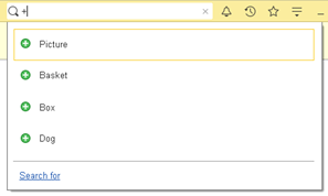
Fig. 508. Own search type is added
An attempt to select any of the displayed lines will result in the message that the URL has a wrong type. The error occurred because the system does not know how to react to our own search type. To implement a custom reaction, create the OnGlobalSearchResultChoice handler in the application module. For description see Selecting search result.
There is one issue in the implemented example: if you enter +2+2 in the search string, the expression will not be calculated. The reason is obvious: we have deleted all default search types in the global search plan. Now, there are two ways to resolve the issue:
-
Compare the search string for strict equality: SearchString = "+".
-
Add expression calculation to the global search plan.
Let us use the second option. To do it, add the text to the OnGlobalSearch handler so that it looks as follows:
Procedure OnGlobalSearch(SearchString, SearchPlan)
If StrStartsWith(SearchString, "+") Then
SearchPlan.Clear();
SearchPlan.Add(StandardGlobalSearchType.Expression);
SearchPlan.Add("CreateGSCommand", "GeneralModuleClient", False);
EndIf;
EndProcedureNow, if you enter +2+2, the expression will be calculated and you will be able to create a picture, a basket, a box, and a dog.
So, by analyzing the user's text input, we can randomly generate the global search plan. A unique global search plan can be generated for each unique input by the user. Some additional parameters, which can accelerate the search or provide the method with additional parameters absent from the global search string, can be passed to each method. These parameters can be unique for each search string. For each search result, you can specify one or several actions that will be displayed next to the search result. For example, if there is an employee list item in the search result, you can specify calling or texting the employee as such actions. Clicking this item in the search result will open the employee card.
Let us complement the example so that when registering luggage, one could specify one of the following picture genres: portrait, landscape, or still life.
To do this, we can utilize the fact that an object of the GlobalSearchResultItem type contains the Actions property. Let us fill this property with the following commands:
Procedure CreateGSCommand(SearchString, SearchResults, AdditionalParameters) Export
Result = New GlobalSearchResultItem("+Picture", "Picture", PictureLib.CreateListItem, , "Add picture.");
Result.Actions.Add("Portrait", "Portrait");
Result.Actions.Add("Landscape", "Landscape");
Result.Actions.Add("Still life", "Still life");
SearchResults.Add(Result);
SearchResults.Add("+Basket", "Basket", PictureLib.CreateListItem);
SearchResults.Add("+Box", "Box", PictureLib.CreateListItem);
SearchResults.Add("+Dog", "Dog", PictureLib.CreateListItem);
EndProcedureAs a result, after entering "+" in the search string, the search result will look as follows:
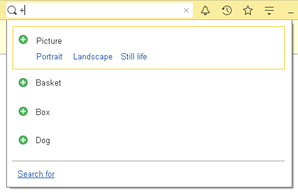
Fig. 509. Custom search actions
Clicking the Portrait, Landscape, and Still life hyperlinks will not result in any actions. That happens because there is no defined action handler of global search results. To change that, define the OnGlobalSearchResultActionChoice event handler in the application module. For more information on how to use the handler, see Selecting an action in the search result.
27.5. Processing search results
27.5.1. Selecting search result
Each search type returns a set of search results (an object of the GlobalSearchResult type) that consists of objects of the GlobalSearchResultItem type to the client. Each item describes the search result (and representation). The SearchType property allows you to specify what type of search will provide the given result. The platform fills this property but does not use it. The developer can act "depending on the circumstances".
If the search result returns a value known to the system, nothing is needed to be done additionally. For example, if a link to an information object is returned, the system will automatically open the form for this link view.
But if the value returned by a custom search requires additional processing, you must use the OnGlobalSearchResultChoice event handler of the client application module.
The selected search result item (the ResultItem handler parameter) and the standard processing necessity attribute are transferred to this event handler.
Now, it is necessary to analyze the selected result and to perform the necessary action:
Procedure OnGlobalSearchResultChoice(ResultItem, StandardProcessing)
StandardProcessing = False;
If ResultItem.Value = "+Picture" Then
// action
ElsIf ResultItem.Value = "+Basket" Then
// action
ElsIf ResultItem.Value = "+Box" Then
// action
ElsIf ResultItem.Value = "+Dog" Then
// action
EndIf;
EndProcedureAny data structure executed in the client application can act as result item value. The data in this structure must also be available on the client.
If upon execution of server search an error is returned, the object of the ErrorInfo type will be sent as a result item value (the GlobalSearchResultItem.Value property).
Whenever results are displayed with the ErrorInfo object specified as their value, in a list of results, the SpecialTextColor style color is used as text and image color (for template images). If the said result has no representation assigned, Search Error is displayed. If the said result has no image assigned, the DialogStop image is displayed.
When you select a result with a search error, the OnGlobalSearchResultChoice handler is not displayed. Instead, a standard dialog box with an error message is displayed.
27.5.2. Selecting an action in the search result
If some actions are specified in search results, these actions are handled by the OnGlobalSearchResultActionChoice event handler in the client application module. If the event handler is not defined, selecting an action in the global search result will have no effect. Actions added to some search results by the platform itself are an exception to the rule.
The global search result itself and the action value specified when adding the action to the search result are passed to the OnGlobalSearchResultActionChoice handler.
This way, if you need to determine the genre of picture to add (for description see Search string processing and new type of search), implement the following handler in the client application module:
Procedure OnGlobalSearchResultActionChoice (ResultItem, Action)
If ResultItem.Value = "+Picture" Then
If Action = "Portrait" Then
// add portrait
ElsIf Action = "Landscape" Then
// add landscape
ElsIf Action = "Still life" Then
// add still life
EndIf;
EndIf;
EndProcedureThe handler checks that the action belongs to the required global search result. Then check the ID of the action to be performed, which was specified when setting actions in the search result.
27.6. Other specifics
It might be necessary to redefine the help displayed in the global search field during the global search setting. The Search label and the key combination for this field activation are displayed there by default. Nevertheless, the developer can install another text, which will be more informative for the user, there. There is a couple of functions for it: GetInputHint()/SetInputHint().
If you write the following in the OnStart event handler:
Procedure OnStart()
GlobalSearch.SetInputHint("What do you want to check in as
luggage?");
EndProcedureThen the global search filed will look as follows:

Fig. 510. Setting an input hint
The search help setting option is another useful specific feature of the program interface.
The search help is displayed either instead of the search history (if no search has been run yet) or after clicking the What To Search For hyperlink in the search history if the search has already been run.
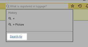
Fig. 511. Search for
GetDescription()/SetDescription() methods are intended to redefine the text displayed when clicking this hyperlink.
The addition to the OnStart handler can be made (an example is given above) so that to get the following text:
Procedure OnStart()
GlobalSearch.SetInputHint("What do you want to check in as
luggage?");
GlobalSearchDescriptionArray = New Array;
GlobalSearchDescriptionArray.Add("Input");
GlobalSearchDescriptionArray,Add(New FormattedString("+", New Font(,,24, True)));
GlobalSearchDescriptionArray.Add(" for quick creation of
objects");
GlobalSearchDescriptionArray.Add(Symbols.LF);
GlobalSearchDescriptionArray.Add(" or arithmetic expression
for result obtainment");
GlobalSearch.SetDescription(New FormattedString(GlobalSearchDescriptionArray));
EndProcedureThe resulting search help looks as follows:
Fig. 512. New description of search
When you develop an application, it might be necessary to call the global search from 1C:Enterprise language so as if it has been done by the user. For example, to run the search by the search string generated in 1C:Enterprise language in accordance with some rules.
The BeginSearch() method can be used in this case. The method gets a search string for input, places this string in the global search field, and starts the search. The result is displayed in the same manner as in the case of interactive input. Keep in mind that if the global search input field is unavailable for input for any reason in the web client, calling the BeginSearch() method in that moment will not trigger the search.
The Search everywhere command accessible in the context menu of some form items can be an example of using the BeginSearch() method. This command is available for a form table, spreadsheet document form field extension, and for a formatted document form field extension. This command places the selected (in the management item) text in the global search field and starts the search.
Chapter 28. Development for mobile devices
28.1. General information
In 1C:Enterprise, you can develop applications for mobile devices (smartphones and tablet computers). The developed applications can function on mobile devices that run Android (http://www.android.com/), iOS (http://www.apple.com/ios/), and Windows (https://www.microsoft.com/windows/). On Windows, devices with touch screens are supported.
Depending on the task, the developer can develop an application for the mobile platform or an application that functions in the mobile client. There are significant differences between these development options:
- Mobile platform application is similar to the thin client that operates with a file infobase located on the same computer as the client application. The mobile platform application interacts with the infobase located on the mobile device. Therefore, the client and server of the application run on a mobile device. Presence of the infobase on the mobile device means that to synchronize data between the mobile device and the main system (if any) it is necessary to implement the necessary tools.
Also, the mobile platform application is a separate technology whose operation requires development of a completely new application or significant adjustments to the current one.
- Mobile client is similar to a thin client for an ordinary computer that uses a web server to access the infobase. In other words, there is no infobase on the mobile device when the mobile client is running. In the mobile client, the client code is executed on the mobile device and the server code is executed on the application server. At the same time, the application server obviously does not run on a mobile device. Since there is no infobase on the mobile device, it means that the mobile client works only if there is a connection between the mobile device and the web server. The mobile client cannot work offline.
For the application to function in the mobile client, instead of rewriting it (like the mobile platform application), you need to adapt it. When adapting, remember that the mobile client has a specific set of features and limitations that you need to consider when adjusting the application. An essential feature of the mobile client is that it supports the technology of configuration extensions.
- Mobile client with standalone mode is a mobile client that supports operation in standalone mode without connection to the infobase. For an application to be able to run in standalone mode, you need to significantly adjust the application that can run in the mobile client. For an application with standalone mode, you must select the metadata to be available in the said mode and implement standalone forms and infobase data synchronization options. In terms of development complexity, the mobile client with standalone mode is located between the mobile client and mobile application.
The mobile application interface is similar to the Taxi interface. In general, the interfaces of the mobile platform application and the mobile client look similar. However, interface operations in each of the possible variants have their own specifics, which you need to consider during application development.
The following terms will also be used in this chapter:
-
Mobile platform is defined on page Types of component interactions.
-
Mobile 1C:Enterprise version. This term will be used to briefly describe all the opportunities provided by 1C for development of applications that run on mobile devices. Therefore, the following two phrases will be equivalent:
-
Mobile platform and mobile client provide access to operations with short messages (SMS).
-
Mobile 1C:Enterprise version provides access to operations with short messages (SMS).
-
-
Mobile application will be used to describe an executable file that can be executed on a mobile device. If you take a closer look, the mobile application can be considered an APK file for Android, an IPA file for iOS, and an APPX file for Windows.
For development, you can use a special tool: the mobile platform or mobile client for developers (mobile 1C:Enterprise version for developers). This version has a number of differences from the mobile application that is distributed through the application store. You cannot host the version in the application store, the version has all the possible permissions that an application may require, and it provides some advanced features regarding the mobile application.
To distribute a mobile application in both cases, you need to use the mobile application builder. It is a specialized tool that facilitates the creation of a package that can be hosted in an application store of respective mobile operating system provider.
This chapter covers the development features for applications running on mobile devices. At the same time, the features common to the application on the mobile platform and the mobile client are described in one section. To describe features common to the mobile platform and mobile client, the term "mobile 1C:Enterprise version" will be used. Features specific to only one development option will be described in its section. Unless otherwise stated, the term "mobile application" means any application that can operate on a mobile device (mobile platform application or mobile client).
It is highly recommended for developers who deal with mobile applications to understand the background of mechanisms used in specific mobile operating systems described in respective documentation. You can find resources for developers online:
-
Android OS: https://developer.android.com/.
-
iOS OS: https://developer.apple.com/.
-
Windows OS: https://developer.microsoft.com/ru-ru/windows.
28.2. Application interface
28.2.1. General information
The mobile 1C:Enterprise version interface is similar to theTaxi interface, where users can switch between windows using the main menu of the application. Navigation in the application depends on the currently active form:
-
A form that does not have an owner and does not store data.
-
For example, a list form or a data processor form.
-
The form is opened by the command from the functions menu. In the left part of the window title, there is a button that opens the main menu of the application. To access the main menu of the application, swipe on the left side of the device screen or tap a special button.
-
A form is opened by other commands or programmatically. In the left part of the window title, there is a button to return to the previous window (<). When such form is closed, the form that was active before opening the closed form is activated. To access the main menu of the application, swipe on the left side of the device screen.
-
-
A form with an established owner.
-
For example, a choice form or an object form opened from a list.
-
When such windows are opened sequentially, a chain of open windows is formed, in which only the most recently opened form is available to the user. Closing the current form activates the previous form in the chain, that is, the form from which the closed form was opened. Note that the user might return to a form different from the one open before switching to the closed form.
-
The left part of the window title contains the button to return to the previous window (<). If you tap it, the current window will be closed.
-
To access the main menu of the application, swipe on the left side of the device screen.
-
-
A form that does not have an owner and saves data.
-
For example, an object creation form called from the main menu of the application or programmatically.
-
When such form is closed, the form that was active before opening the closed form is activated.
-
The left part of the window title contains the button to return to the previous window (<). If you tap it, the current window will be closed.
-
To access the main menu of the application, swipe on the left side of the device screen.
-
-
Forms that lock the interface.
-
For example, a form that has the Window opening mode property set to Lock parent window or Lock the entire interface.
-
The window title contains a button associated with the form command:
-
If there is saved data (flag of the Saved data attribute), the standard Cancel button is displayed.
-
If there is no saved data, the standard Close button is displayed.
-
If the form contains one of the Cancel, Close, or No commands, this command is displayed.
-
-
The main application menu is unavailable for a form that locks the entire interface. For a form that locks the owner window, to access the main menu of the application, swipe on the left side of the device screen.
-
-
A mobile application running on iOS inherits the interface scale set for the operating system. Thus, if interface items have larger size in the operating system, they will be larger in the mobile application as well.
Upon mobile application startup, a full-screen image specified by the application developer is displayed. A few moments later, a 1C Company logo and a copyright notice appear at the bottom, overlapping the splash screen:
-
In portrait orientation, about 10% of the screen area.
-
In landscape orientation, about 15% of the screen area.
28.2.2. Global command interface
The mobile 1C:Enterprise version interface can display one form on the screen at a time. It allocates the maximum of screen blank space. Therefore, the commands that generate the command interface of the main section (navigation and action panels) on the personal computer are collected in the main menu of the application. The main application menu also contains a command to return to the home page, a list of sections (the commands of each section are displayed as a submenu), as well as commands to display information about the program and go to the list of applications. To open the main menu of the application, swipe on the left side of the screen (if available) or tap a special button≡ located on the left side of the window title.
You can also configure the role-based visibility of the command interface (see Configuration command interface editor).
28.2.3. Home page
The home page supports displaying a different number of forms, depending on the option you are using:
-
The mobile platform can display only one form.
-
The mobile client displays all available home page forms. The form selection algorithm and display method are described below.
-
The mobile client with standalone mode is similar to the mobile client but considers distinctive features of the standalone mode (see below).
Displayed forms are selected according to the following rules:
-
Forms that are unavailable according to access rights are excluded from the list of forms specified in the settings of the home page work area.
-
After that, forms disabled by functional options are excluded from the remaining list.
-
Displaying the home page forms:
-
Mobile platform. From the remaining forms (as a result of the previous steps), the first visible form is selected, while the desktop forms are traversed from top to bottom, first the left column, then the right one (if the location of the home page forms is set to two columns).
-
Mobile client. The forms selected for displaying are arranged as tabs whose switch is located at the top. When you start the application, two tabs are displayed: the first visible form and a special tab that you can tap to load all other home page forms. After loading all forms, a separate home page tab is created for each form.
-
Behavior of the mobile client with standalone mode in ordinary mode is similar to that of the mobile client. If the mobile client is in standalone mode or the Expect bad connection checkbox is selected in the application settings, then forms unavailable in the standalone configuration are skipped when you select home page forms. In this regard, to make user operations independent of the mode, we recommend that you select the first home page form that 1) has an applied meaning and 2) is available in the standalone configuration.
-
If no form is found when generating the home page in a standalone configuration, the home page displays a form whose content depends on the operation mode:
- Standalone mode:
- Header: Standalone mode.
- Form text: Standalone mode functions are available.
- Expect bad connection checkbox is selected:
- Header: Connection is not established.
- Form text: Standalone mode functions are available.
- When connection with the main server is established:
- Header: Connection is established.
- In the form, tap Start... to load home page forms.In addition to the form, the home page can contain the command interface of the main section. The components of the command interface of the main section on the mobile version is similar to that on the platform for a personal computer (except for the see also group). The main section command interface is displayed as a matrix of buttons (each button is associated with one command), grouped by pages. The image on the button is obtained from the associated command. If a command does not have a custom image, the default image for that group of commands is used.
The commands are displayed to fill the work area of the window as much as possible. Groups of commands are placed on pages to avoid their division between different pages. So, if one group of commands does not fit completely in the remaining space after the previous group, it is displayed on a new page. If all commands do not fit on the screen, they are placed on several pages that can be scrolled.
28.2.4. User message
The display of messages to the user depends on how many unseen messages are currently available. The first unseen message is displayed as a dialog box with the message text and the OK button. After the second message is received, the All messages button appears in the advanced dialog box. The All messages button has a counter with the total number of incoming messages.
If you tap All messages, the messages panel with all unread messages opens. If you tap OK in the dialog box or close the messages panel, the list of messages is cleared. Tapping a message activates a form item if the message is associated with one. To re-open the message list, you need to re-call the action that opens the list.
28.3. Mobile 1C:Enterprise version
28.3.1. General information
This section describes the features that are used in the same way in both the mobile platform application and the mobile client.
28.3.2. File operations
All applications on mobile devices operate within a special feature that ensures safe program execution (sandbox). This feature ensures that applications have limited access to the file system of the mobile device. When you develop a mobile application, you might need to access the file system. For example, to store intermediate data or to record documents generated in the system for later exchange with other computers.
Special functions are used to access these file system locations:
-
TempFilesDir() returns the temporary files directory for this application. If necessary, the directory can be cleaned up by the operating system.
-
UserDataWorkDir() returns the directory recommended for storage of the user's "long-term" data.
-
DocumentsDir() is a directory of documents to be exchanged with an external (in relation to a mobile application) environment.
-
MobileDeviceLibraryDir() returns the library directory of the mobile device. The library type is determined by the method parameter. The following library types are available: audio files, video files, and pictures.
Regardless of the actual capabilities of the mobile OS, we do not recommend that you use any other file system directories of the mobile device for security reasons and due to requirements of mobile OS developers for applications.
To save a file to a mobile device, use the interactive option of the GetFileFromServerAsync() method. Please remember that you cannot save files to mobile device library directories using objects for operations with files. To save files, use the GetFileFromServerAsync() or GetFilesFromServerAsync() methods.
If you need to use a file located on a mobile device in some way in the application, you can use the FileDialog object for file selection. On Windows, use the standard 1C:Enterprise dialog box. On Android and iOS, use a special dialog box that allows you to access various mobile device storage sections. The sections are described by the following values of the FileDialogSection system enumeration:
-
List of recently used files (on Android only): FileDialogSection.Recent.
-
Combined list of photo and video files (mobile device gallery): FileDialogSection.Gallery.
-
List of mobile device audio files: FileDialogSection.Audio.
-
Mobile device document folder (result of the DocumentsDir() method): FileDialogSection.Documents.
-
Content of the working user data directory (result of the UserDataWorkDir() method): FileDialogSection.Files.
Depending on the selected mode, the created dialog box has a number of behavior features:
| Choosing the directory | Opening the file | Saving the file | |
|---|---|---|---|
| Available sections | Documents Files | All | All |
| Multiple choice | No | Yes | No |
| Folder creation | Yes | Only in the Documents section | Only in the Documents section |
| Sorting | Alphabetical | Any | Alphabetical |
| Presentation | List | Any number | List |
In the gallery and section with audio files, you can create a new file directly in the dialog box.
To limit the sections used in the file selection dialog box, for example, to allow selecting audio files only from the corresponding section, use the FileDialog.Sections property. You can put an array that contains values of the FileDialogSection system enumeration to this property. If the array is empty or not specified (the property is set to Undefined), all available sections will be shown. Sections in the dialog box are displayed in the same order they are listed in the FileDialog.Sections property. If the developer sets only one section to display, the section list is not displayed in the dialog box.
The file selection dialog box allows you to select files by file name mask and by MIME type. To filter items by mask, use the Filter and FilterIndex properties of the FileDialog object. The Filter property allows you to specify a list of masks to filter the list, and the FilterIndex property specifies the default mask. When the file list is displayed in the dialog box, the files that do not match the set mask are unavailable for selection and displayed as "inactive". When you change the filter, the dialog box view changes. To filter items by MIME type, use the FileDialog.MIMEType property. This property contains an array where each element represents MIME types that the dialog box must display. The dialog box will display only those files whose MIME types are specified in the property and match the mask specified in the filter. If the FileDialog.MIMEType property is not specified or set to Undefined, the following MIME types are used for filtering:
-
For the Gallery, Documents and Files sections: image, video, and all subtypes.
-
For the Audio section: audio and all subtypes.
If you need to specify a certain "MIME type and all subtypes" manually, the filter value (for example, of the audio file type) looks as follows: audio/*.
You can select several files in the file selection dialog box. To enable this feature on a personal computer or a mobile device, use the FileDialog.MultipleChoice property:
-
If the property is set to False, you can select only one object in the dialog box. This object will be passed to the calling code.
-
If the property is set to True, the dialog box is initially opened in single choice mode. To switch to multiple choice mode, tap More actions and select the respective command.
This allows us to unify the behavior of the file selection dialog box and reduce the number of actions required to perform an atomic action. By atomic action, we mean selection of a single file. Let us consider an example. We need to implement a dialog box for adding one or several files to an infobase on a mobile device. Users usually add one file at a time even if there are several files, but advanced users might want to select several files at once. To enable multiple choice, set the MultipleChoice property to True. Regular users will still be able to select one file in one tap. Advanced users, however, will need to enable multiple choice in the dialog box, select files to add, and tap the selection button. If the MultipleChoice property is set to False, users cannot enable this mode interactively.
On a mobile device, the name of a file in the library may not match how the file is displayed by system applications. However, the file view cannot be used to identify the file, pass as parameters to file manipulation methods, and so on. The view is intended solely for display to the user. To obtain a view, use the File.GetMobileDeviceLibraryFilePresentation() method.
The following example shows how to select and display an arbitrary file on a mobile device:
Dialog
= New FileDialog(FileDialogMode.Open);
Sections = New Array;
Sections.Add(FileDialogSection.Gallery);
Dialog.Sections
= Sections;
Dialog.MultipleChoice
= False;
Result = Await
Dialog.ChooseAsync();
If Result = Undefined Then
For Each Object In Result Do
Message("Selected object:" + Object);
EndDo;
EndIf;As a result, it is possible to formulate the following recommendations for working with files on the mobile device:
-
If a directory or file path begins with the content: string, you can use only the following methods to write files to this directory: GetFileFromServerAsync() or GetFilesFromServerAsync(). You can use these paths in the constructors of the following objects: File, BinaryData, Picture, and MobileDeviceApplicationRun. You can also use these paths as parameters of the following methods: RunApp(), GotoURL(), CopyFileAsync(), MoveFileAsync(), DeleteFilesAsync(), and FindFilesAsync().
-
If the path to the directory (or file) does not start with the content: string, you can use all the mobile platform file features to perform operations with such files and paths. Keep in mind that mobile operating systems operate with different file systems. Therefore, the path separators and masks of all files are different on different mobile operating systems.
-
To get the mask of all files and the file path separator in a universal way that considers the operating system used and code execution environment, use the special GetAllFilesMask() and GetPathSeparator() methods. To unify with the application code for a personal computer, you can use methods that return the specified parameters separately for the client and the server of the application: GetClientAllFilesMask()/GetServerAllFilesMask() and GetClientPathSeparator()/GetServerPathSeparator().
When displaying information from mobile device libraries, you might need to show smaller copies (preview, presentation image) instead of full-sized images. This reduces the probability of getting a low memory error in a mobile application that actively uses pictures or video files from mobile device libraries. To get a presentation picture for a file located in the mobile device library, use the File.GetMobileDeviceLibraryFileThumbnail() method. When you use this method, remember that to get a presentation picture, the path to the file being processed must belong to the content scheme (begin with the content: string).
28.3.3. Picture operations
For mobile devices, a regular picture with variants is used, which is used by the platform for a personal computer. For the description of a picture format and its manifest, see Common pictures.
For iOS devices, the following pictures from the set are used:
-
Conventional screens: mdpi picture;
-
Retina screens: xdpi pictures.
For Android devices, pictures that correspond to the screen resolution of the applied device are used.
A mobile device supports the following objects: Picture and ProcessingPicture. You can create an object of the Picture type based on a file path that belongs to the content:// scheme. When you operate with the Picture and ProcessingPicture objects, keep in mind that a mobile device imposes restrictions on the availability of object properties and methods, as well as on method operations. These restrictions are listed in the Syntax Assistant.
See also:
-
File management on a mobile device (see File operations).
-
Picture processing (see Picture operations).
28.3.4. Forms
28.3.4.1. General information
For those features or configuration objects that are not supported by the mobile 1C:Enterprise version, the properties of form items associated with this feature or object will be unavailable. For example, the Shortcut key property or drag-and-drop events.
The principles and rules of form generation for the mobile 1C:Enterprise version mostly match the ones for the thin client. However, there are some features to consider when you develop mobile application forms:
-
Smartphone screens are mainly vertically oriented (portrait orientation), so the form is significantly limited in its width and slightly limited in height.
-
Horizontal scrolling of forms is unusual on mobile devices and scroll bars on mobile devices are not constantly displayed. For that reason, the user may not notice that the form (report or table) shows only partial information. To avoid this situation, the developer must ensure that all form items fit the screen width, for example, by using groups with the Horizontal if possible grouping. If the developer has not done it, the form will be only partially functional, since the horizontal scroll bar is not supported in forms on the mobile platform.
28.3.4.2. Available form items
You can use the following form items in mobile application forms:
-
Fields of the following types:
-
Input field
-
Label field
-
Radio button field
-
Picture field
-
Checkbox field
-
Indicator field
-
Slider field
-
Chart field
-
Spreadsheet document field
-
-
Button
-
Table
-
Decoration: label and picture
-
Groups of all kinds
28.3.4.3. Placement of form items
Groups, including the form itself, and most of the form items are displayed as lists, which is typical for mobile interfaces. Form items are conventionally divided into three types:
- Located only in a list row. This group includes the following items:
-
Input field
-
Label field
-
Radio button field
-
Button
-
Chart field
-
Can be located in a list row. The group includes decoration.
-
Cannot be located in a list row. This group includes the remaining items.
The "list display" phrase means the following:
-
The group has a background that is different from the color of the form.
-
A row list is either a form item or a group with horizontal grouping of items.
-
Items located in a group with horizontal grouping are arranged in one row.
-
Items located in a group with vertical grouping are located in separate rows.
-
If there are items in the group with vertical grouping that cannot be located in a list row, a gap is displayed in the list.
-
If a group has a displayed title, an indent is generated before the group.
-
Visual row separators are horizontal lines whose display cannot be controlled.
The behavior peculiarity of type 2 items is that they are located in a list row only if they are grouped with type 1 items. Type 2 items are not presented as a list by themselves.
Many form items do not have borders (input fields and buttons whose border color is set to Auto). For that reason, the alignment of input fields in forms (like on the platform for personal computers) has no practical function. Instead, there is special algorithm that aligns values in input fields. Depending on the presence and location of the input field title, information in the field is aligned in different ways:
-
If the field title is missing or is not displayed on the left, the numerical values are aligned to the right, and the remaining characters are aligned to the left.
-
If the field title is on the left:
-
In the fields with text editing, text is aligned to the left.
-
Numeric values are aligned to the right.
-
The alignment of fields of other types depends on whether there is a text editing field in the group with these fields or not. If there is such field, the alignment of the remaining fields is carried out in the same way as the alignment of this field. Otherwise, to the right.
-
The form title is displayed only in the window title and is not duplicated in the form.
As mentioned above, horizontal scrolling of forms is not applied on mobile devices. However, vertical scrolling of forms is acceptable. Based on these prerequisites, the mobile 1C:Enterprise version tries to automatically rebuild the form so that it fits the mobile device screen. In the adaptation process, the width of form items is reduced for those items whose width in the configuration is set so that it exceeds the actual screen width on a mobile device. The width for such items is adjusted to fit the screen width of the mobile device in the current orientation without horizontal scrolling. In addition to changing the width, the system might attempt to reduce the number of displayed form items to improve the visual appearance of the form. To enable or disable such restructuring, use the Method of collapsing items by importance form property (CollapseItemsByImportance). The Auto value is interpreted as Use.
To make form adjustment easier for the mobile version, form items (and table columns) have the Display importance property (DisplayImportance). By changing the value of this property, developers can achieve the desired form presentation on the device screen. This property value is processed by the mobile client as follows:
-
More important items are given more space on a form.
-
If a more important item is located below less important ones, and these less important items occupy more than three rows of a form, the less important items are combined and placed in a collapsible group. Keep in mind that the height is more important than the number of items in any case. In other words, three form rows can fit three items if each of them occupies only one row or one item that occupies three rows.
-
If the first or last of the collapsible items is the command bar, it is not collapsed as it can refer to an important item.
-
If a more important item is located within a hierarchy of groups or pages, and less important items are located above it in different hierarchy points occupying more than three rows, a collapsible group is generated at each hierarchy level.
-
If there are several items of higher importance, less important items between them are placed in a collapsible group if they occupy more than three rows.
-
Less important items that are below the last more important item are not collapsed.
-
If items of different importance are also located inside a collapsible group, the algorithm is applied recursively to this group.
-
The collapsible group title is generated as follows:
-
If an already existing group becomes collapsible, the group title is preserved.
-
If a single item with a specified title is added to a collapsible group, this item's title is used for the group.
-
Otherwise, the group title is a combination of comma-separated titles of the items included in the collapsible group.
-
If the DisplayImportance property is set to Auto for a form item, the actual property value is determined by the following rules:
-
VeryHigh for the form item that displays data from the main form attribute (and subordinate attributes).
-
High if the item is stretched vertically and is one of the following items:
-
Form table displaying a dynamic list
-
Spreadsheet document field
-
Chart field of any kind/type
-
Formatted document field
-
HTML document field
-
-
If an item is a command bar, then:
-
High if the source of commands for the command bar is the controlled form.
-
The importance value of an item that is the source of commands for the command bar.
-
The importance value of the most important item in the same group as the command bar provided that no command source is set for the command bar.
-
-
The Standard value for all other items.
28.3.4.4. Features of displaying form items
28.3.4.4.1. General features
The form does not display an empty mark for both form items and table items.
Field titles are displayed without the ":" characters at the end of the text.
28.3.4.4.2. Forms
Use the CurrentItem property to get and set the current form item. However, setting the current form item does not switch it to editing mode and is not displayed visually. To switch a form item to editing mode, use the BeginEditingItem() method.
If any actions are performed upon form opening, consider that the mobile device screen will not be updated until all the form handlers are completed.
28.3.4.4.3. Input fields
To facilitate input field operations for touch screens of mobile devices, value editing directly in the input field is not supported in all fields, except for text input fields and fields with enabled autocomplete. The input field behaves like a button whose title displays the presentation of the current value, and tapping this button opens a specialized editor. If autocomplete is used in the input field, you can clear the value by tapping Clear located to the left from the window title.
If you long press the input field, it opens a context menu, which consists of standard system commands and commands that were added to this menu during development.
To display the clear, open and adjust buttons, set the corresponding input field property to Yes. Besides, you can control the visibility of the clear and open buttons, which are displayed directly in the input field. To do it, use the AutoShowClearButton and AutoShowOpenButton properties. These properties are processed only if the corresponding property of the input field is set to Yes. The following behavior options are possible (the values of the AutoShowClearButton and AutoShowOpenButton properties):
-
Filled only. In this case, the button is displayed only if the value in the field differs from the default value for the used type or if the input field displays data of the union type.
-
Always. The clear button is always displayed.
-
Auto. Behavior depends on the property:
-
The AutoShowClearButton property is interpreted as Filled only.
-
The AutoShowOpenButton property is interpreted as Always.
-
The selection button is never displayed. The StartChoice event is triggered upon clicking the input field. If a separate form is used to edit a field value, a special marker (>) is placed next to the field. Tapping it opens this form. The location and appearance of editors are different on tablets and phones.
The multiline input field is always in text input mode. Such input field does not support value selection and autocomplete. If the input field is linked with data of any type other than the String type, the value of the MultiLine checkbox is ignored for such input field. A multiline input field can be displayed in three different ways:
-
Automatic adjustment of the field height to the text height (to avoid scrolling). Adjustment occurs when the field occupies the entire width of the form, the field height is not specified (the Height property), and the field can stretch vertically (the VerticalStretch property).
-
The field has a specified height and vertical scrolling inside the field is allowed. The field is displayed in this way when the field height is specified (the Height property) and the field cannot stretch vertically (the VerticalStretch property).
-
The field occupies as much space in the form as possible. A field is displayed in this way when the field height is specified (the Height property) and the field can stretch vertically (the VerticalStretch property).
The value of the Input hint property is not displayed in the multiline input field.
For the mobile platform, additional properties of the input field are also relevant. They ensure more efficient use of the application. You can use these properties to further customize the input field for implementation of some specific tasks only if the input field displays data of the String type:
-
Use the AutoCorrectionOnTextInput property to enable automatic correction of entered text. Behavior depends on the settings of the virtual keyboard in use. Auto means that automatic correction is enabled for multiline input fields, but not for normal single-line ones.
-
Use the SpellCheckingOnTextInput property to enable spell checking when entering text. On Android, this property is ignored, since this feature is controlled by the system and depends on other settings.
On Windows, this property and the AutoCapitalizationOnTextInput property are always enabled at the same time. When the SpellCheckingOnTextInput property is set to Use, the operating system automatically capitalizes first letters in sentences in entered text. This change will be made regardless of the value of the AutoCapitalizationOnTextInput property. The value of the AutoCapitalizationOnTextInput property is used on other operating systems.
Auto means that automatic check is applied to multiline input fields, but not to normal single-line ones.
- Use the AutoCapitalizationOnTextInput property to control automatic capitalization in entered text. The behavior depends on the operating system used and the settings of the virtual keyboard used.
On Windows, this property and the AutoCapitalizationOnTextInput property are always enabled at the same time. When the SpellCheckingOnTextInput property is set to Use, the operating system automatically capitalizes first letters in sentences in entered text. This change will be made regardless of the value of the AutoCapitalizationOnTextInput property. The value of the AutoCapitalizationOnTextInput property is used on other operating systems.
Can take the following values:
-
No. Automatic capitalization is disabled.
-
Words. The first letter of each word is automatically capitalized.
-
Sentences. The first letter of each sentence is automatically capitalized.
-
All characters. All entered characters are automatically capitalized.
-
Auto. In multiline input fields, it is interpreted as Sentences. In ordinary single-line fields, it is interpreted as No.
-
Use the SpecialTextInputMode property to specify a special type of virtual keyboard when typing in the input field:
-
No. Default virtual keyboard is used.
-
Digits and punctuation. The virtual keyboard to enter digits and punctuation characters is used.
-
URL. The virtual keyboard to enter URLs is used.
-
Email. The virtual keyboard to enter email addresses is used. This keyboard contains the @ character.
-
Phone number. The virtual keyboard to enter phone numbers that contain digits and the * and # characters is used.
-
Digits. The on-screen keyboard to enter digits is used.
-
Auto. It is interpreted as No.
-
On Android tablets, all virtual keyboard types, except for the Phone number type, can look the same, due to the large amount of free space on the screen.
When developing forms that involve different types of information (phone numbers, email addresses, and so on), you might need to name the input completion button on the used virtual keyboard. That will help the user understand what action will be performed after tapping this button. To do this, use the OnScreenKeyboardReturnKeyText input field property. The value of this property indicates the text to be displayed on the input completion button. On Android, if you specify Continue, Next will be displayed instead. If you specify Connect, Enter will be displayed instead. On Windows, this property is ignored. Text management on input buttons is not supported.
28.3.4.4.4. Checkbox field
Checkboxes can display only two states. On iOS, checkboxes are always displayed as tumblers.
28.3.4.4.5. Radio button field
The Radio button field is always displayed in a separate vertical group, and the number of columns is not adjustable. Radio button fields cannot be combined with other items in the same row.
The Tumbler field is always displayed in one row, and the number of columns is not adjustable.
28.3.4.4.6. Button
If a button is located in a vertical group, it is stretched to the width of the parent group. The button text is aligned to the left edge of the button, except when the color of the button border is different from the default value. In this case, the text is aligned to the center of the button.
28.3.4.4.7. Group
When displaying groups of a managed form, only indenting for groups with the Normal selection and Strong selection display modes is supported.
When displaying a collapsible group (the Behavior group property is set to Collapsible), note the following features:
-
The collapsible group title (see Group) is displayed as a row that can be tapped.
-
The collapsible group is always displayed with the Picture display variant and its (display option) setting is ignored.
Pages groups support several implementation options for the tabbed panel. The panel presentation and behavior depend on the value of the Show tabs property:
-
Tabs are at the top.
-
Tabs are displayed as a tumbler. If the title text does not fit in the allocated space, it is displayed partially with ... at the end. Pictures in titles are not displayed.
-
Pages are located inside the group under the list of tabs.
-
The active tab is displayed by title inversion.
-
-
Tabs are at the bottom.
-
Tabs are displayed as a panel of buttons. If the title text does not fit in the allocated space, it is displayed partially with ... at the end. Pictures in titles are displayed. Title text is always displayed under the picture.
-
Pages are located within the group above the list of tabs.
-
If there is not enough screen space to display the titles of all pages of the group, the More button is added to the end of the list. Tap this button to open the list of titles for all pages of the group.
-
-
Tabs are on the left.
- Tabs are displayed as a list. Tap a tab to open a new window with the tab contents that will replace the current form (with the tab list). To return to the list of tabs, tap < located in the upper left part of the page header.
-
Scrolling.
-
Tabs are displayed as points below pages. Text and pictures are not displayed. To switch between pages, the user must swipe right or left in the pages area.
-
Pages are located inside the group above the points that denote the number of tabs.
-
In the personal computer platform, this value is interpreted as Tabs are on the left.
-
-
Tabs are on the right.
- It is not supported by the mobile platform.
28.3.4.4.8. Table
Current row operations
Behavior of the current row in the table is determined by the Use current row table property (CurrentRowUse):
-
Selection. In this case, the CurrentRow, CurrentItem, and CurrentData properties are defined only upon execution of:
-
Context command handler
-
Activation event of a row or cell
-
Row edit events
-
The rest of the time, these table properties are set to Undefined. For a form command that requires data from the current row, you need to explicitly specify such need in the Use current row form command property. You also must specify the table whose data will be used by the command. Use the Used table property for that.
In the list, the current row is visually defined for a short time, upon tapping the row.
If the current row is set programmatically, the set value is retained until the top-level 1C:Enterprise language method (called by the system from the interface, not from another 1C:Enterprise language method) is completed.
This value is recommended for tables that are not logically related to any other data (including tables).
- SelectionPresentation. In this case, the current row always exists if the table contains at least one row.
In the list, the current row is always visually defined.
This value is recommended for tables that are logically related to some other data (including tables).
- SelectionPresentationAndChoice. In this case, the current row always exists if the table contains at least one row.
In the list, the current row is always visually defined. Also, there is a button on the right side of the row that activates and selects the row.
- Auto. This value is interpreted as Selection on both the mobile platform and mobile client.
The CurrentParent property is defined in the following cases:
-
Always in hierarchical lists.
-
In the tree view if the CurrentRow property is defined.
Displaying table columns
The table in the mobile platform never has horizontal scrolling. For that reason:
-
Column fixing in the table is ignored.
-
The value of the HorizontalScrollBar property is ignored.
-
The display of columns that do not fit in the visible part of the table depends on the value of the Behavior for horizontal compression managed form table property (BehaviorOnHorizontalCompression) and on the Display importance property (DisplayImportance) of columns of this table:
-
Hide items by importance. In this case, columns that do not fit in the form are hidden based on their Display importance values. This way, columns with Very low importance are hidden first, columns with Low importance are hidden after that, and so on. If there are several columns with the same importance, columns are hidden based on their location from right to left. In other words, the more to the left the column is located in the table, the higher are its chances to be displayed (other things being equal).
-
Move items by importance. In this case, columns are hidden as their importance decreases (similar to Hide items by importance). The values of hidden columns are displayed in a separate row, in small print, comma-separated, and color-interleaved.
-
Auto interpretation depends on where the configuration is used:
-
On the mobile platform, it is interpreted as Hide items by importance.
-
On the mobile client, it is interpreted as Move items by importance.
-
-
Various table modes
The table in the mobile application can be displayed in three modes:
-
Main mode
-
Multiple row selection mode
-
Row sorting mode
The main mode is similar to the table display mode on the platform for personal computers, except for display of current and selected rows. In the mobile platform, these rows are not displayed. The exception is the short-term highlighting of the current row of the table when the form is opened. The form table automatically adjusts to the size of the content if the following conditions are met simultaneously:
-
The table covers the entire width of the form.
-
The fixed table height is not set.
-
The table is stretched vertically.
-
The object that displays the table contains less than 100 rows of data. If there are more than 100 rows, scrolling will be available.
The multiline row selection mode is characterized by a special column with checkboxes, with the help of which the selection is made. The column is always displayed first. In this mode, contextual table commands are available and affect the entire selection at once.
The row sorting mode is characterized by the presence of a special column with a marker that can be used to drag a row. This column is always displayed last. In this mode, the table context commands are not available.
Multiple selection mode in the table (the SelectionMode property is set to Multiple) on the mobile platform is not visually displayed. Its existence is marked by the Select multiple command available in the command bar associated with the table. When this command is selected, the table switches to multi-row selection mode.
If the multiple selection mode is set (the Multiselect property is set to True), the table is opened in the multi-row selection mode, and the command for switching to this mode is not displayed in the command bar.
If changing the order of rows is available in the table (for example, the document table), to activate this mode, you need to perform the Permutation of rows command available in the command bar associated with the table. In this case, the table switches to the row sorting mode, and selected rows are reset (if any).
The table supports only two row input modes (the RowInputMode property): at the end of the list and at the end of the window. The row selection mode is always used: Row (the RowSelectionMode property). The actual value of the property is ignored.
Context menu
The form table supports the context menu. To open it, the user must swipe left from the right table border or long press a row.
Filling the command bar and context menu has important differences from the platform for personal computers. On the platform for personal computers, allocation of commands between the command bar and the context menu is a question of form design. On the mobile platform, it is a question of the functional model due to absence of the current row. If a command uses table properties associated with the current row, this command must be located in the context menu. If such command is located by the developer somewhere else, the system can forcibly move it to the context menu. The exception to this rule is the case when a command can perform its function both with and without the current row. For example, the Create command of the dynamic list that displays hierarchical catalog data belongs to such commands. Non-context command use involves creating an item in the catalog root. Context command use, on the other hand, creates an item in the current group.
To indicate to the system that a command requires current row data to be performed, use the CurrentRowUse form command property. To link a form command to a table whose data it must process, use the AssociatedTable command property. Using this property means that it is impossible to implement a command on the mobile platform that simultaneously processes data from more than one table. To control command placement, use the RepresentationInContextMenu command property:
-
Auto. The command that uses data of the current row is always located in the context menu. A command that does not use data of the current row is always located in the command bar of the table.
-
OnlyInContextMenu. The command is always located in the context menu.
-
AdditionallyInContextMenu. The command is located in the context menu and in the command bar of the table.
-
No. The command is located only in the command bar of the table.
Search string
Managing the search string location is also different from the platform for personal computers. Depending on the value of the SearchStringLocation table property, the following behavior is possible:
-
Auto. To access the search string, tap the button on the command bar if the table displays a dynamic list, being the main attribute of the form. In other cases, swipe down the table header.
-
Top, Command bar. The search string is located between the table command bar and the table header.
-
Pull down. To access the search string, swipe down the table header.
-
Form header. The search string is located in the form header.
-
Bottom. There is no search string.
-
No. There is no search string.
If two or more form tables have the SearchStringLocation property set to Form header, this will be interpreted in the same way as if each of these tables had this property set to Top.
Table height in the form
When scrolling the table associated with a dynamic list, translucent buttons appear in its upper and lower parts. If you tap them, you will go to the list beginning or end (respectively).
To control the table height in a managed form, use the Height management option property (HeightControlVariant):
-
In form rows. The table height is set using the Height property of the managed form table. If the value of this property is 0, then the table height will be 8 units for a table displaying a dynamic list and 4 units in all other cases.
-
In table rows. In this case, the table height is set using the HeightInTableRows property of the managed form table. If the value of this property is 0, the table height will be 7 rows for a table displaying a dynamic list and 3 rows in all other cases.
-
By content. If the table is linked to a dynamic list, the table height is defined by the value of the HeightInTableRows property. If the value of this property is 0, then the table height is defined by the value of the HeightInTableRows property.
If the table is not associated with a dynamic list, all table rows are fully displayed, but not less than 3 and not more than 100 rows. After the 101st row is added, the table is compressed to the height specified in the HeightInTableRows property. If this property is set to 0, the Height property is used to define the height. At the same time, vertical scrolling becomes available for the table contents. After the 101st row is deleted, the table is stretched to a height, enough to accommodate 100 rows of the table.
The By content value is recommended for tables with a small number of rows.
- Auto. It is interpreted as By content.
Data update
You can update data displayed by the table in a style adopted on mobile devices by trying to pull the list down or up when you reach the first or last (respectively) row of the displayed data (pull to refresh). To control this feature, use the Refresh request table property (RefreshRequest):
-
No. Update can be performed only through the command of the command bar of the table.
-
Any other value means that the update can be initiated by trying to pull a list in the appropriate direction. If you do it, you will see respective animation in the table area outside the data.
If you refresh the list this way, the RefreshRequestProcessing table event handler is called. If the table is adapted based on its content, the RefreshRequestProcessing table handler is not called.
If the dynamic list associated with the table does not contain displayed data, then No data to display is displayed inside the table. The table that is not associated with the dynamic list does not display any text when there is no data to display.
Editing table data
Instead of editing data in the row of the table associated with a table or a value table, the mobile platform provides a special system form. This form contains all columns of the current table row displayed in the parent form. In this form, field grouping is implemented if this grouping is implemented in the table settings, but in fact only the first grouping level is recreated. Deeper grouping levels are not recreated in this form. All fields of deeper grouping levels are placed in the parent group of the first level.
When you use a system form, keep the following features in mind:
-
The columns whose View only property is set are displayed in the system form also with locked editing.
-
In the system form, picture and label fields are not displayed.
-
Conditional appearance of the form is applied to the system form.
-
All event handlers are called.
-
The system form is not editable in Designer and cannot be programmatically modified.
After returning from editing mode, the edited row is briefly highlighted.
28.3.4.5. Dynamic list
The dynamic list used in the mobile platform has the following features:
-
You can programmatically manage dynamic list settings. For interactive customization, you need to manually implement respective setup forms.
-
Interactive list display is not supported.
-
You can sort items by tapping their titles. You cannot perform sorting by several columns in this way.
28.3.4.6. Form panels
The form navigation panel is implemented using a special menu that is displayed at the bottom of the form as a radio button. Tapping the switch button opens the corresponding form.
Form command bar:
-
In the top display mode:
-
The command bar is located in the form header, to the right of the text.
-
If the command bar contains standard command pairs OK-Cancel and Yes-No, the negative action button is transferred to the left side of the form header, and the positive one is displayed in the command bar of the form. In the More menu, there are all commands except for the command with a negative action, which was transferred to the form header.
-
If the command bar does not contain the above pairs of commands, but contains the standard Cancel, No, or Close form command, the button with such command is moved to the panel in the header on the left.
-
The command located on the left side of the form header will be displayed with a special symbol (<), but will perform its original function.
-
When a button is displayed in the command bar of the form, the Display property of this button is considered. The command properties associated with this button are ignored when defining the display mode of the button.
-
If the command bar contains a default button, it is always displayed in the header first.
-
If there is enough free space on the right side of the header to display the remaining commands, they are displayed there. Otherwise, the More button is displayed, and the system tries to ensure that the More button is not the only one. If the command displayed on the right side of the header is not defined, it will be the first command from the list of the remaining commands, and the remaining ones will be located in the More menu.
-
-
In the bottom display mode:
-
It is docked when scrolling the form.
-
When the keyboard appears, it is not displayed.
-
The list of standard commands does not include commands for direct deletion (for reference type objects), calling for help, displaying a list, or changing a form. The standard Save and close and Post and close commands are displayed in the command bars with the Done title.
For applications running on iOS, remember that the system mechanisms for closing a form do not ask the user whether to save data when the form with modified data is closed.
The command bar associated with the table is located above or below the table and does not exceed the width of the table. When scrolling the table, the command bar always remains in the visible area.
28.3.5. Hardware or external keyboard
The mobile 1C:Enterprise version supports hardware or external detachable keyboards made for mobile devices. This keyboard is supported in input fields that display data of the Number and Date type. When you use a hardware or an external keyboard, input fields on a mobile device will look the same as without this keyboard. Fields that display other data types do not support a hardware or an external keyboard.
If you use a hardware or an external keyboard, you can:
-
Use keyboard shortcuts that the developer specified for form items when developing the configuration. Standard 1C:Enterprise keyboard shortcuts are not supported. The system behavior depends on which form item the keyboard shortcut is assigned to:
-
Input field. Keyboard shortcut activates the input field.
-
Decoration. If a decoration of the Label type must be displayed as a hyperlink, pressing a keyboard shortcut is similar to tapping a hyperlink on the screen. Hyperlinks in a formatted string are not activated when you press the keyboard shortcut.
-
Page group. Keyboard shortcut selects the specified page.
-
For other form items, the keyboard shortcuts do nothing.
-
-
Navigate through form items. To do this, press Tab (to navigate right and down) or Shift + Tab (to navigate left and up). To navigate through form items, you can also use arrow keys, joystick keys, or other cursor control keys on a hardware or an external keyboard.
If you press Tab on the last form item or press Shift + Tab on the first item form, the active item form loses the focus. If you press these keys again, it activates the first item (when you press Tab) or the last item (when you press Shift + Tab) of the current form.
For iOS and some Android devices, pressing Tab inserts a tab character to a multiline input field.
The cursor control in multiline input fields controls the cursor within the input field but does not change the active form item. For Android devices, the cursor control changes the active form item if the cursor is in the first or last position of the text in the input field.
If you use the cursor control in the horizontal direction, the cursor in a single-line input field moves over the text in the input field. If the cursor is in the first or last position of the text, it changes the active form item.
-
When you press Esc or Back on a hardware or an external keyboard, the current form is closed if it contains buttons with the following standard commands: Close or Cancel.
-
Pressing Enter executes an action associated with the default button of the current form. If no default button is selected for the form, pressing Enter does nothing.
28.3.6. Special features of the mobile device
28.3.6.1. General information
Special mobile device features refer to features that are not available on personal computers using standard operating system interfaces. These features include telephony, tools, notifications, advertising, and so on. The software providing these features depends on the vendor of the mobile operating system and its architecture. Mobile operating systems, such as iOS and Windows, provide all necessary interfaces "independently". Android provides some interfaces "independently", while other interfaces rely on specialized software provided by various vendors. We can say that classic Android consists of Android Open Source Project (AOSP, https://source.android.com/) and a set of mobile services provided by some company. Vendors of mobile services:
-
Google Inc. These services are commonly referred to as Google Mobile Services (GMS). They are used most often.
-
Huawei Technologies Co., Ltd. The services are referred to as Huawei Mobile Services (HMS).
-
IP JSC VK. The services are provided by the RuStore app store.
Most of mobile devices contain only GMS. However, there are devices that contain only HMS and also devices that contain all mobile services (GMS, HMS, and RuStore).
The 1C:Enterprise mobile version that runs on Android supports any combination of mobile services. If all the services are installed on the mobile device and the mobile application supports all mobile services, then:
-
If RuStore is available, it takes precedence over other services.
-
If GMS is available, it takes precedence over HMS.
The mobile application builder allows you to manage the support for each of the sets of mobile services, including the build with disabled support for all sets of services. Thus, the availability of one of the sets of services is determined not in the configuration, but in the builder (while building the application).
When describing any specific functionality, we will separately describe actions required when using each set of services (GMS, HMS, or RuStore). If such description is missing, there is no difference between services or only GMS is supported.
28.3.6.2. Used functionalities
Used functionality feature combines management of the following features:
-
Specify the mobile operating system features that the mobile application will use. When you specify the functionality, the system automatically determines the mobile operating system permissions that the Mobile Application Builder will set for a mobile application to be built.
-
The permission request text that will be displayed to the user when the mobile application first requires access to the functionality protected by the user permission request.
-
Size of a mobile application to be built. If a functionality is not included in the configuration, the respective module of the mobile 1C:Enterprise version might not be included in the built application when you build a mobile application. This behavior determines another feature: if you attempt to call any method of a disabled module in the mobile application, an exception will be thrown.
Let us take a closer look at the interaction between the used functionality setup and the code in 1C:Enterprise language. To determine whether a functionality is allowed for a mobile application, use the MobileApplicationFunctionalitySupported() method. If the method returns True, the requested features are enabled in the built application. You can also check whether a feature associated with the used functionality is available on this device. For example, if you need to check whether the device supports dialing, use the TelephonyTools.NumberDialingSupported() method (for more information, see Telephony operations). However, this method is related to the Telephony/Dialing functionality. So, the full process of checking whether you can dial a number might look as follows:
If MobileApplicationFunctionalitySupported(MobileApplicationFunctionalities.NumberDialing) Then
If TelephonyTools.NumberDialingSupported(Undefined) Then
// here you
can use dialing
EndIf;
EndIf;Note that this code is redundant. The application developer almost always knows which functionalities their application uses. That is why you can simplify the code to the following:
If TelephonyTools.NumberDialingSupported(Undefined) Then
// here you
can use dialing
EndIf;However, the first option is also possible. When you use the MobileApplicationFunctionalitySupported() method in the mobile client, the list of selected functionalities is checked not only on the mobile device but also on the server. The method returns True only if the functionality to be checked is enabled both on the mobile device and the server. If functionalities can be enabled or disabled for various mobile application versions when developing a mobile client configuration, we recommend that you allow using the MobileApplicationFunctionalitySupported() method to prevent runtime exceptions. This precaution is redundant in a mobile application.
Below you can find information about the object model of 1C:Enterprise language, its features and used functionalities related to them. Besides, you can find information about the system behavior upon an attempt to use a disabled functionality:
| Functionality | When disabled | Affects |
|---|---|---|
| Bluetooth printers | Exc | |
| NFC | Und | The availability of the NFCTools global context property and linked data types |
| Push-notification | Exc | DeliverableNotificationSubscriberID, DeliverableNotifications, ReceiveNotificationSubscriberID() |
| WiFi printers | Exc | |
| Automatically send text messages | Exc | Non-interactive usage of the TelephonyTools.SendSMS() method |
| Music library | Exc | The availability of the music library when using multimedia libraries. For example, in the file opening dialog box |
| Picture and video libraries | Exc | The availability of picture and video libraries when using multimedia libraries. For example, in the file opening dialog box |
| Biometrics | Exc | SecureStorageAccessProtectionMethod, AdditionalUserVerificationMethod, BiometricVerificationMethod, SecureStorage, AdditionalUserVerification |
| Videoconferences | Und | Using video conferences of the collaboration system and screen sharing in the mobile client |
| Audio playback and vibration | Exc | Availability of the MultimediaTools.TextPlaybackSupported(), MultimediaTools.PlayAudio(), MultimediaTools.PlaySoundAlert(), MultimediaTools.PlayText(), MultimediaTools.StopAudioPlayback(), and MultimediaTools.StopTextPlayback() methods |
| Audio playback and vibration in background | Exc | Availability of the MultimediaTools.PlayAudio() and MultimediaTools.PlayText() methods |
| In-app purchases | Exc | Availability of the InAppPurchases global context property and related objects |
| Incoming "Share" requests | Und | Using features of processing incoming "Share" requests for the selected file types |
| Geofences | Exc | Availability of the Geofence object and tools for operating with geofences of the LocationTools global context property. |
| Location | Exc | Availability of the LocationData and LocationProviderInformation objects, methods of working with location of the LocationTools global context property |
| Location in background | Und | |
| Deliverable notifications | Exc | Availability of the DeliverableNotification, DeliverableNotificationSubscriberType, and DeliverableNotifications objects |
| Access to all files | Exc | Access to the file system (including file management) outside the application directory (only for Android). |
| Text message log | Exc | Availability of the TelephonyTools.SMSLogSupported() and TelephonyTools.GetSMSLog() methods |
| Phone log | Exc | Availability of the CallLogs, CallLogCallType, TelephonyToolsCallEventVariant, TelephonyTools.CallLogSupported(), and TelephonyTools.GetCallLog() objects and methods |
| Audio recording in background | app1 | Background use MultimediaTools.MakeAudioRecording() |
| Calendars | Exc | Availability of the AccountCalendarData, AccountCalendarEventData, CalendarEventData, Account, GlobalCalendarKey, GlobalCalendarEventKey, LocalCalendarKey, LocalCalendarEventKey, and CalendarsManager methods |
| Camera | Exc | Availability of the DeviceCameraType, VideoQuality, DeviceCameraResolution, CameraLightingType, PhotoStamp, MultimediaTools.VideoRecordingSupported(), MultimediaTools.PhotoSupported(), MultimediaTools.GetSupportedCameraResolutions(), MultimediaTools.MakeVideoRecording(), and MultimediaTools.MakePhoto() objects and methods |
| Contacts | Exc | Availability of the AccountContactData, LocalContactKey, ContactAccount, and ContactManager objects and methods |
| Local notifications | Exc | Availability of the DeliverableNotifications.AddLocalNotification() and DeliverableNotifications.CancelLocalNotifications() methods |
| Microphone | Exc | Availability of the MultimediaTools.AudioRecordingSupported() and MultimediaTools.MakeAudioRecording() methods |
| Multimedia | Exc | Availability of the MultimediaData and MultimediaTools objects |
| File exchange with personal computer | Und | |
| Processing all types of incoming "Share" requests | Und | Using features of processing incoming "Share" requests for all file types |
| Call handling | Exc | Availability of the TelephonyToolsCallEventVariant, TelephonyTools.CallsHandlingSupported(), TelephonyTools.AttachCallsHandler(), and TelephonyTools.DetachCallsHandler() objects and methods |
| Printing | Exc | Availability of the PrintDialogUseMode, SpreadsheetDocument.Print(), Planner.Print(), and RepresentableDocumentBatch.Print() objects and methods |
| Getting text messages | Exc | Availability of the TelephonyTools.SMSReceivingSupported(), TelephonyTools.AttachSMSMessageHandler(), and TelephonyTools.DetachSMSMessageHandler() methods |
| Speech recognition | Exc | Availability of the SpeechProcessing global context property and related data types (in speech recognition functionality) |
| Backup using OS | Und | |
| Ads | Exc | Availability of the AdRepresentation global context property and related data types |
| Speech synthesis | Exc | Availability of the SpeechProcessing global context property and related data types (in speech synthesis functionality) |
| Document scanning | Exc | Availability of the MultimediaTools.DocumentScanningSupported(), MultimediaTools.ShowDocumentScanning(), MultimediaTools.ScanDocumentsAsync(), and MultimediaTools.CloseDocumentScanning() methods |
| Barcode scanning | Exc | Availability of the MultimediaTools.BarcodeScanningSupported(), MultimediaTools.ShowBarcodeScanning(), MultimediaTools.CloseBarcodeScanning() methods |
| Application usage statistics | Und |
In the table:
-
Exc means that an attempt to use a functionality that is disabled in the configuration properties throws a runtime exception.
-
Und means that the system behavior is undefined. In general, the behavior of the mobile 1C:Enterprise version is determined by the used mobile operating system and the applied feature. In some cases, the action might not be executed, a mobile operating system error might occur, and so on. If the developer does not include a functionality in the configuration, they automatically refuse to use all mobile version features associated with this functionality.
-
app1 means that audio recording is possible only in an active application. In a minimized application, audio is not recorded.
28.3.6.3. Telephony operations
The mobile 1C:Enterprise version provides a set of features that allow you to make calls from mobile applications. Calls can be made with or without user confirmation. The system also provides access to the call log and the ability to handle events that occur when receiving or making phone calls. In the application, you can define supported telephony features. To do it, use the NumberDialingSupported(), CallLogSupported(), and CallsHandlingSupported() methods of the TelephonyTools object. Call processing is possible only on Android.
Dialing is done as follows:
If TelephonyTools. NumberDialingSupported() Then
TelephonyTools. DialNumber(PhoneNumber, CallDirect);
EndIf;The CallDirect parameter is responsible for how the subscriber's call will be made:
-
If the parameter is set to True, the number dialing is triggered automatically upon a method call. A standard call program interface appears on the screen.
-
If the parameter is set to False, the call handling application is opened when the method is executed, and the specified number is set there. The user only needs to tap the call start button after that.
Mobile devices running Android provide access to the call log. You can iterate log records with a required filter. To perform operations with the log, use the GetCallLog() method of the TelephonyTools object.
The following example demonstrates getting a list of all missed calls on a mobile device.
If TelephonyTools.CallLogSupported() Then
Log = TelephonyTools.GetCallLog();
Filter = New DataCompositionFilter;
NewItem = Filter.Items.Add(Type("DataCompositionFilterItem"));
NewItem.LeftValue
= New DataCompositionField("CallType");
NewItem.ComparisonType
= DataCompositionComparisonType.Equal;
NewItem.RightValue
= CallLogCallType.Missed;
NewItem.Use = True;
LogRecords = Log.FindRecords(Filter);
For each
Record In LogRecords Do
// call list
processing
EndDo;
EndIf;When you perform operations with the call log, remember that the log is filtered using the DataCompositionFilter object.
To process call events (on Android devices), you can attach/detach the call handler. After the call event handler is registered in the system, it is called upon any event occurrence, and call data is passed to that handler. The handler does not support actual call management. The standard operating system program is used for that.
You can use this feature to implement, for example, your own call log for a mobile application or a missed call reminder.
&AtClient
Procedure CallHandlerManagement(AttachHandler)
If NOT
TelephonyTools.CallsHandlingSupported() Then
// call
processing is not supported
Return;
EndIf;
Handler = New NotifyDescription("CallsProcessing", ThisObject, "Parameters");
If ProcessCallEvents Then
TelephonyTools.AttachCallsHandler(Handler);
Else
TelephonyTools.DetachCallsHandler();
EndIf;
EndProcedure
Procedure CallsHandler(PhoneNumber, Date, EventVariant, CallType, AddlParameters) Export
// call events
processing
EndProcedure28.3.6.4. Operation with messages (SMS and MMS)
The mobile 1C:Enterprise version provides a set of tools to perform operations with SMS and MMS messages. Messages can be sent and received. Access to the list of messages is determined by the mobile operating system in use. Sending messages is possible both interactively and completely programmatically.
The mobile 1C:Enterprise version provides some tools to determine features of the mobile OS in use. For that, the TelephonyTools global context object has the following methods: SMSSendingSupported(), SMSReceivingSupported(), and MMSSendingSupported(). Depending on the mobile operating system in use, the following restrictions for message operations are applied:
-
On iOS:
-
Subscription to receive SMS/MMS is unavailable.
-
SMS/MMS cannot be sent programmatically.
-
-
For Android:
- MMS cannot be sent programmatically.
-
On Windows:
-
Subscription to receive SMS/MMS is unavailable.
-
SMS/MMS cannot be sent programmatically.
-
The message in 1C:Enterprise is represented by the SMSMessage object. Sending a message looks as follows:
&AtClient
Procedure SendSMS(To, Text, SendInteractively)
SMS = New SMSMessage();
SMS.Text = Text;
StringRecipients
= StrReplace(To, ",", Chars.LF);
For Counter=1
In StrLineCount(StringRecipients) Do
SMS.Recipients.Add
(TrimAll(StrGetLine(StringRecipients, Counter)));
EndDo;
TelephonyTools.SendSMS(SMS, SendInteractively);
EndProcedureAs a value of the To parameter, several comma-separated phone numbers can be passed. The SendInteractively parameter defines how the message will be sent:
-
If the parameter is set to True, the message is sent immediately.
-
If the parameter is set to False, the default messaging application for the mobile OS in use is opened. In this application, the form for sending a message with filled fields is opened. In this case, the user must manually tap the button for sending a message in the opened form.
To convert an SMS message into an MMS message, you need to add attachments to messages. To do it, use the SMSMessage.Attachments property. Specify the MIME type of the passed data as the value of the MIMEType property of the MMSAttachment object. For example, for a JPEG file, this is image/jpeg.
In the mobile 1C:Enterprise version, you can subscribe to notifications of received SMS messages if the mobile OS in use supports this feature.
&AtClient
Procedure AttachMessagesReceiptHandler()
MessageRecipient = New NotifyDescription("MessageReceipt", ThisObject);
TelephonyTools.AttachSMSMessageHandler(MessageRecipient);
EndProcedure
&AtClient
Procedure MessageReceipt(Message, AdditionalParameters) Export
Message(Message.Sender
+ "-" + Message.Text);
EndProcedureWhen an incoming message is received, the notification handler will be called to process the received message. Messages received using the attached notification handler will also be available from the system messaging application.
To check the accessibility of the message log, use the TelephonyTools.SMSLogSupported() method. If the mobile OS in use provides access to the message log, it becomes possible to receive messages according to the applied filter.
The following example demonstrates getting a list of all unread messages on a mobile device.
If TelephonyTools.SMSLogSupported() Then
Log = TelephonyTools.GetSMSLog();
Filter = New DataCompositionFilter;
NewItem = Filter.Items.Add(Type("DataCompositionFilterItem"));
NewItem.LeftValue
= New DataCompositionField("Read");
NewItem.ComparisonType
= DataCompositionComparisonType.Equal;
NewItem.RightValue
= False;
NewItem.Use = True;
LogRecords = Log.FindRecords(Filter);
For each
Record In LogRecords Do
// message
list processing
EndDo;
EndIf;When you perform operations with the SMS log, remember that it is filtered using the DataCompositionFilter object.
When you filter messages by the PhoneNumbers field, consider some features:
-
The user can specify fragments of numbers only if the string is used as the right value of the filter item and the comparison type is DataCompositionComparisonType.Contain or DataCompositionComparisonType.NotContains. Spaces, parentheses, and hyphens in the number are not ignored.
-
Indication of names from the address book (list of contacts) is not supported.
-
If an array of numbers is specified as the filter value, the message meets the condition only if there is the same number of numbers in the message and filter and all these numbers match.
The search returns a list of messages ordered starting from the most recent messages.
28.3.6.5. Location tools
28.3.6.5.1. General information
Numerous mobile devices support determination of mobile device coordinates. They also can convert received coordinates into addresses and vice versa. To access these features, you can use the location provider. Each provider is described by a name and a specific set of parameters (features). A specific location provider may not support all features.
The general algorithm for operation with location tools is as follows:
- The required provider is selected. In each case, you need to select a provider that is most suitable for completion of assigned task. In general, it is preferred that you select a provider with minimum power consumption and maximum accuracy in terms of coordinates determination.
Example:
// Define a provider that does not lead to spending
// funds and uses a cellular network to determine
// coordinates
RequiredProvider = Undefined;
Providers = LocationTools.GetProviders();
For Each Provider In Providers Do
If NOT
Provider.Paid and Provider.UsesCellNetwork Then
RequiredProvider
= Provider;
Break;
EndIf;
EndDo;
If RequiredProvider = Undefined Then
Message("Required
provider not found");
Else
Message("Provider
found: " + RequiredProvider.Name);
EndIf;If you need to get the most energy-efficient provider or the most accurate provider, you can use the GetMostPowerSavingProvider() or GetMostAccurateProvider() methods, respectively.
- The coordinates are determined using the selected location provider. Two methods are used to obtain the coordinates. The GetLastLocation() method returns the latest location data received by the selected provider. Among the properties of the LocationData object (which returns the GetLastLocation() method), there is the Date property that describes when the location data was received. If this data is obsolete, call the UpdateLocation() method for the location provider to refresh the location data. One of the method parameters determines the timeout for location determination. If the method is terminated upon timeout, the actual determination of coordinates in this case depends on the implementation specifics of a particular mobile operating system version.
Example:
// If the location on this device has never been
performed
// or completed more than an hour ago, update the
location and
// receive specific coordinates
Coordinates = LocationTools.GetLastLocation(ProviderName);
If Coordinates = Undefined Or
CurrentDate()-ToLocalTime(Coordinates.Date) > 3600 Then
LocationTools.UpdateLocation(ProviderName, 60);
Coordinates = LocationTools.GetLastLocation(ProviderName);
EndIf;- If required, you can subscribe to coordinates change. If you no longer need the subscription, you can to turn off the notification of coordinates change.
After receiving the location data, you can perform several auxiliary operations related to the received location:
-
Get the address by coordinates.To do this, use theGetAddressByLocation() method.
-
Get location coordinates by address. To do this, use the GetLocationByAddress() method.
-
Show a map that displays the coordinates of one or more points. To do this, use the ShowOnMap() method. This feature is unavailable for some mobile OS. Use the MapRepresentationSupported() method to determine whether one or more points are displayed on the map. To display points on the map on any mobile OS, use a branded application by the operating system developer.
Note. Note
- To use methods that convert coordinates into addresses and vice versa, the mobile device must have access to the Internet.
Note. Note 2. The location feature is not supported in the background on iOS devices.
28.3.6.5.2. Getting the key for Google Maps
Note. Note. The description of operating with the web interface is given as of the time of writing the documentation.
For a mobile application to support location on Android using GMS, get a special key for Google Maps. The key is obtained as follows:
-
Log in to the Google Developer Console (https://console.developers.google.com/project).
-
Create a project by clicking Create project.
-
Enable the Google Maps service. To do this, select an application and click Products and Services – API Manager. The menu is available in the upper left corner of the page, next to the Google APIs label. On the Library page, enter Google Maps Android API in the input field. In the list, below the input field, select Google Maps Android API. On the page that opens, click Enable. The hyperlink is located at the top of the page, to the right of the Google Maps Android API label.
-
Obtain an API Key. To do this, select Credentials in the menu on the left side of the page. In the Credentials section, click Create credentials and select API Key in the drop-down menu. After creating the key, click Close in the resulting dialog box.
-
Create a mobile application group in the mobile application builder, which was set up appropriately first. After that, copy the contents of the Parameter of getting the Google Maps key field.
-
For the Key restriction radio button, select Android application. Click Add resource: package name and checksum. Insert the copied data into the SHA-1 certificate checksum field. Then, at the end of the inserted line, select the full application ID and transfer it to the Package name field. Not that the checksum must not end with ";".
-
After key generation is completed, it will be displayed in the API Key field. Enter the resulting value in the Google maps key field located in the mobile application group form. Finally, save the mobile application group.
28.3.6.5.3. Getting the key for operating with Map SDK (Huawei maps)
Note. Note. The description of operating with the web interface is given as of the time of writing the documentation.
For a mobile application to support location on Android using HMS, get a special key for Huawei Map SDK. To get the key, follow these steps (skip the steps for creating an application if it is already created in AppGallery Connect and in the mobile application builder):
-
Register as a Huawei developer (registration documentation: https://developer.huawei.com/consumer/en/doc/start/registration-and-verification-0000001053628148 ).
-
Sign in to AppGallery Connect (https://developer.huawei.com/consumer/en/service/josp/agc/index.html#/).
-
Create a project (click Add project).
-
Create an application (click New app). Set the appropriate application parameters:
-
Platform: Android.
-
Device: Mobile phone.
-
Application category: App or Game.
-
Copy the contents of the Hash of SHA256 signature key field from the vendor settings for Android OS (Service – Set up provider parameters – Parameters for Android). The mobile application builder must be configured correctly by this time.
-
In AppGallery Connect, select My projects and the desired project. In the project settings on the Main information tab, click Application data. In the SHA-256 certificate thumbprint input field, enter the value received in the previous step and click Save.
-
Go to the API management tab. Enable Map Kit.
-
On the General information tab, in the Application data section, download the agconnect-services.json file.
-
Upload the downloaded file to the mobile application group in the mobile application builder:
-
Go to the For Android tab.
-
Enable the Use Huawei services checkbox.
-
Import the received JSON file in the Using AppGallery Connect group.
- After completing these steps, the mobile application built using the builder will be able to use Map SDK features.
28.3.6.5.4. Getting the key for RuStore
Note. Note. The description of operating with the web interface is given as of the time of writing the documentation.
For a mobile application to support location on Android using RuStore, get a special key for RuStore Maps SDK. To get the key, follow these steps (skip the steps for creating an application if it is already created in RuStore and in the mobile application builder):
-
Register in RuStore as a developer (registration documentation is available athttps://www.rustore.ru/help/developers/developer-account).
-
Sign in to the RuStore developer console (https://dev.rustore.ru/).
-
Create an application (click + Add application). Set the appropriate application parameters:
-
Application type: Universal.
-
Monetization type: Free / Paid.
-
The application name in the console. It will be visible only to you. This value can be changed later.
-
Select an application in RuStore. Then go to Maps and geoservices. In the Create service token card, click + Create token.
-
Copy the created token. You will need to specify it in the mobile application group in the mobile application builder:
-
Go to the For Android tab.
-
Enable the Use RuStore services checkbox.
-
Insert the copied token in the Token for operations with geographical maps field.
- After completing these steps, the mobile application built using the builder will be able to use RuStore Maps SDK features.
28.3.6.6. Multimedia operations
28.3.6.6.1. Audio
Recording
Mobile devices can record audio information. To define whether the operation can be performed, use the MultimediaTools.AudioRecordingSupported() method.
In this case, if a mobile device supports this feature, the mobile version provides the following methods to record audio:
-
MultimediaTools.MakeAudioRecording(). Starts the audio recording interface. The program in 1C:Enterprise language will run after the requested action is performed (recording is completed).
-
MultimediaTools.StartAudioRecording(). Starts background audio recording. The application will continue running. To stop recording, you can use a special button on the screen. You can stop recording programmatically by calling the MultimediaTools.StopAudioRecording() method. To notify the application about the end of the recording, use a handler that is passed to the StartAudioRecording() method.
To manage audio recording parameters, use the AudioRecordingParameters object. Use this object to specify the following parameters:
-
Audio recording mode: mono or stereo. It is specified by the AudioRecordingChannelUse property.
-
Recording bitrate. Determines how much (in bits) one second of recording will take. Unit of measure: bits per second. It is specified by the EncodingBitrate property.
-
Audio sampling rate. Determines how exactly the audio will be recorded. In other words, it sets the frequency at which the audio is digitized. Unit of measure: kHz. It is specified by the SamplingRate property.
-
Format in which the recorded data will be received. Determines the format of data to be received. The data format, MIME type, and file extension depend on the property value. It is specified by the AudioRecordingFormat property.
You can specify recording parameters both for synchronous audio recording and background recording. To do this, use the respective parameters of each method. To enable background recording and ensure that it does not stop when the device goes to sleep, specify the Audio recording in background functionality in the Used mobile application functionality configuration property (see Properties related to development for mobile devices).
Playback
In the mobile 1C:Enterprise version, you can play audio notifications, play audio files, and perform speech synthesis. The ability to perform speech synthesis depends on the language in which you want to perform it.
To play a sound notification (short sound or vibration), use the MultimediaTools.PlaySoundAlert() method. You can play either a standard system sound or a sound file whose name is passed as the Sound parameter of this method. This sound file must be part of the mobile application. However, you cannot attach resources with playable files on the mobile platform for developers. To attach the specified file to the mobile application, use mobile application builder tools (see Mobile Application Builder). For that reason, you can check the use of sound notifications from files only in a built application. To control vibration when playing a sound notification, use the Vibration parameter of the PlaySoundAlert() method. If the file name with the sound notification is specified without an extension, the following extensions (depending on the OS) are used by default:
-
Android: .mp3
-
iOS: .caf
-
Windows: .mp3
You cannot stop or pause the notification playback. It is always played back completely.
Calling the Signal() global context method is equivalent to calling the MultimediaTools.PlaySoundAlert(SoundAlert.Default) method.
To play an audio file, use the MultimediaTools.PlayAudio() method. The playback source can be the MultimediaData object (the MakeAudioRecording() or StartAudioRecording()), the BinaryData object (which contains the audio file of the required format) or a file name (the String type). Playback of the audio file included in the mobile application is not supported. If an application must handle the playback stop state, specify a notification handler (in the StopPlaybackHandler parameter) that will be called if playback is stopped or interrupted.
To stop the audio file playback, use the MultimediaTools.StopAudioPlayback() method. If the audio file is not currently playing, nothing will happen.
In terms of playing various audio file formats, we recommend that you rely on the MIME file type. Audio files can be played if these files have the following MIME types (depending on the mobile OS used):
-
Android: audio/3gpp
-
iOS: audio/mp4
-
Windows: audio/aac
In addition, you can play audio files with the following MIME types:
-
AAC format: audio/aac
-
MP3 format: audio/mpeg
-
WAVE format: audio/vnd.wave (for Android version 4.1 and later).
Playback of audio files whose MIME types differs from those listed above is not supported.
Further, you can find a simple example of a form with two buttons. Tapping one of them (the PlayAudio() handler) selects a file and starts playing it. Tapping the second button (the Stop() handler) stops the playback.
&AtClient
Procedure PlayAudio(Command)
Dialog = New FileDialog(FileDialogMode.Open);
If Dialog.Select() Then
Data = Dialog.FullFileName;
MultimediaTools.PlayAudio(Data);
File = New File(Dialog.FullFileName);
Message(""
+ File.GetMobileDeviceLibraryFilePresentation() + " with duration of
" + MultimediaTools.GetAudioDuration(Data) + " seconds");
EndIf;
EndProcedure
&AtClient
Procedure Stop(Command)
MultimediaTools.StopAudioPlayback();
EndProcedureOn the mobile platform, you can use a speech synthesizer built into the operating system. To check whether a synthesizer for a specific language is available, use the MultimediaTools.TextPlaybackSupported() method. If a speech synthesizer is available, you can play texts using the MultimediaTools.PlayText() method. To process the interruption of speech synthesis, you can set the appropriate handler using the StopPlaybackHandler parameter. To interrupt text playback, use the MultimediaTools.StopTextPlayback() method.
28.3.6.6.2. Photo and video
With mobile devices, you can take photos and record videos. For various mobile devices, these features may or may not be available. To determine whether an operation can performed, you can use the following functions: PhotoSupported() and VideoRecordingSupported().
If a mobile device supports a feature, you can use the global context method that activates the necessary system application to perform the required action: MakePhoto() and MakeVideoRecording().
Since mobile devices can have two cameras (front and rear), you can select any of them for operations on the mobile platform. To do this, use the DeviceCameraType system enumeration when determining the features of a mobile device and when performing an action.
Front = MultimediaTools.PhotoSupported(DeviceCameraType.Front);
Rear = MultimediaTools.PhotoSupported(DeviceCameraType.Rear);The code above allows you to determine which of the two device cameras supports photography. Using these methods, you can determine the presence of a particular camera on the device. You can also specify the camera to be used for taking photos and recording videos. If the camera type is DeviceCameraType.Auto, it is interpreted on devices as follows:
-
If the device has two cameras, the rear camera is used.
-
If the device has one camera, this camera is used (depending on availability).
You can also specify some additional photo and video parameters that affect the final result.
For photos, you can specify the following parameters in addition to the camera type:
-
Required camera resolution. If you specify a resolution that is not supported by the device, resolution closest to the specified one is selected. To get the list of supported resolutions, use the GetSupportedCameraResolutions() method of the MultimediaTools object. For iOS devices, this parameter is ignored.
-
Picture quality. Defines the compression degree of JPEG files. 100 means maximum quality.
-
Color mode of the resulting picture: color or black and white. For iOS devices, selecting the black and white mode does not affect the camera interface. However, the resulting picture will be black and white.
-
Initial flash mode when opening the camera interface. To control it, use the LightingType parameter of the MakePhoto() method. You can manually turn on or turn off the flash or let the device determine the flash mode automatically.
-
Use the Mark parameter to control the insertion of the date and time the photo was taken or free text in the right lower corner of the photo. Pass the PhotoStamp object as the parameter value.
To speed up the acquisition of picture data on Android, we recommend that you do the following:
-
If the application does not require the front camera, forcible set the rear camera as the main one by using the CameraType parameter of the MultimediaTools.MakePhoto() method. If automatic camera selection mode is set, switching to the front device camera in the camera interface is not recommended.
-
The recommended device position for taking pictures is horizontal (wide side down) with camera on the left.
-
Do not enable photo conversion to black and white (the BlackAndWhite parameter of the MultimediaTools.MakePhoto() method) without obvious need.
-
If possible, reduce the resolution and quality of the resulting photo to a reasonable value (the Resolution and Quality parameters of the MultimediaTools.MakePhoto() method). For example, setting the Quality parameter to 50%, and the Resolution parameter to 50% of the maximum camera resolution can reduce the time required to take a photo by 1.5 times.
For video recording, in addition to specifying the camera type, you can also specify the quality of the resulting video. This parameter is ignored on iOS devices.
28.3.6.7. Barcode scanning
Barcode scanning is supported on mobile devices with a camera. To access this feature, the platform provides a special interface.
Note. Note. To effectively scan barcodes, it is desirable that the camera of the mobile device has the ability to automatically focus the camera lens (autofocus). Otherwise, scanning barcodes will be difficult.
The general scheme of operation with a barcode scanner is as follows:
-
You need to determine whether scanning is supported. To do this, use the BarcodeScanningSupported() method of the MultimediaTools global context object.
-
If scanning is supported, use the ShowBarcodeScanning() method of the MultimediaTools object to open a special barcode scanning interface. During scanning, a special handler with data on the scanning result is called.
-
To close the scanning interface manually, use the standard Android button to go to the previous form. To close the scanning interface programmatically, use the CloseBarcodeScanning method of the MultimediaTools()object.
Consider an example that demonstrates the scanning feature. In the example, we used a simple form with a button that opens the scanning interface and a flag for closing this interface after a single scan. The scanned barcode will be displayed as a message.
Note. Note. This example is not a completed tool. It only demonstrates how to use the scanning feature.
In the form, create the CloseInterface attribute of the Boolean type and add an item that displays this attribute to the form. Create the OpenScanningInterface form command and add it to the form as well. The form module looks as follows:
// The OpenScanningInterface form command handler
&AtClient
Procedure OpenScanningInterface(Command)
ScanHandler = New NotifyDescription("ScanHandling", ThisObject);
CloseHandler = New NotifyDescription("InterfaceCloseHandling", ThisObject);
MultimediaTools.ShowBarcodeScanning("Point the camera at the barcode", ScanHandler, CloseHandler);
EndProcedure
&AtClient
Procedure ScanHandling(Barcode, Result, Message, AdditionalParameters) Export
If Result Then
Text = "
" + Barcode;
Else
Text = "Error: " + Message;
EndIf;
If CloseInterface Then
MultimediaTools.CloseBarcodeScanning();
EndIf;
Message(Text);
EndProcedure
&AtClient
Procedure InterfaceCloseHandling(AdditionalParameters) Export
Message("The
scanning interface is closed");
EndProcedure
&AtClient
Procedure OnOpen(Cancel)
If NOT
MultimediaTools.BarcodeScanningSupported() Then
Raise
"Barcode scanning is not supported";
EndIf;
CloseInterface
= False;
EndProcedureWhen the scanning interface is opened, two notification descriptions are passed to the ShowBarcodeScanning() method. The first notification is triggered (the ScanHandler parameter) if the system has successfully recognized the barcode. The second notification (the CloseHandler parameter) is triggered when the barcode scanning window is closed. The interface can be closed both interactively and programmatically. The programmatic option is demonstrated in the ScanHandling() notification handler. To close the interface interactively, tap Back in the scanning interface.
When opening the scanning form, you can specify which type (or types) of barcodes will be expected by the recognition system. For this purpose, use the BarcodeType parameter of the ShowBarcodeScanning() method. The parameter can take the following values:
-
Undefined or BarcodeType.All. In this case, the platform will try to determine which of the supported barcode types is currently being shown to the camera. This requires more time and, as a result, more battery power.
-
A specific value of the BarcodeType system enumeration (but not generalizing values). In this case, the developer clearly states that they plan to scan a specific type of barcode and there is no need to waste time trying to figure out what barcode the device's camera sees. The most efficient method (both in terms of speed and energy consumption).
-
Array of specific values of the BarcodeType type. In this case, the developer assumes that several barcode types can be scanned, but this number is less than can be specified using generalizing values.
-
Generalizing values:
-
BarcodeType.Linear means that any of the linear barcode types (for example, EAN and UPC) will be expected.
-
BarcodeType.Matrix means that any of the matrix barcode types (for example, QRCode and PDF417) will be expected.
-
-
Speed and efficiency in the last two cases will be somewhere in between trying to scan any barcode and a specific type of barcode.
The list of supported barcodes does not depend on the mobile platform used and is described by values of the BarcodeType system enumeration.
28.3.6.8. Email operations
The mobile 1C:Enterprise version provides application developers with several ways to operate with emails. One method allows you to implement a full-fledged email client on the 1C:Enterprise platform (the InternetMail object and related objects). The other method allows you to send email messages only by using the default email application installed in the system (the MailTools object).
When email messages of the InternetMailTextType.HTML type are sent using the MailTools object (on Android), the message text is converted into Spannable format. The email sent is displayed by most email clients.
If you use email message texts of the InternetMailTextType.HTML type (on OS Android), using the following features is not recommended:
-
Cascading tables of styles
-
Embedded tables
-
Embedded images
-
Fonts of different sizes
We recommend that you check the display of emails on as many devices as possible to minimize the dependence on the implementation differences of different operating systems and mail application versions.
Note that the InternetMailTextType.RichText email message text type is not supported by the MailTools object.
28.3.6.9. Contact list operations
operationsContact list is a database that stores information about the subjects with whom the owner of the mobile device communicates. The contact description contains the contact identification data, addresses, phone numbers, and other information necessary to communicate with the subject. Also, accounts of various services can be registered on the mobile device. An account is a set of information that users use to identify themselves in any service. For example, this is a username and password. There is always an account on the mobile device that describes the device itself (local account).
Each record in the contact list is associated with a single account. The mobile operating system can synchronize the list of contacts with the account data (depending on the OS settings). If the contact is associated with a local account, information is not synchronized, and all data is located only on the mobile device.
The main information about the contact is stored in objects of ContactData type. Objects of this type contain all information about the contact, except for the link of the contact with the account. There are several data types in the contact description that can contain more than one value. Such data includes phone numbers, addresses, email addresses, and so on. To store such data, use object arrays of the ContactDataItem type. To store the list of identifiers in instant messaging applications, use an array of ContactDataItemInstantMessaging objects.
The accounts registered on this mobile device for contact synchronization are described using theContactAccount object.
The AccountContactData object generates the link between the contact account and actual contact list items. In addition to information about the contact and account, this object also contains an ID by which the list of contacts on the mobile device and the account are synchronized. One could say that the GlobalContactKey property of the AccountContactData object is similar to the Link property for applied 1C:Enterprise objects.
To identify a contact on a mobile device, use theLocalContactKey object. All operations with contacts (creation, modification, deletion, and search) are performed using this object. To perform operations with contacts, use the contact manager (the object of the same name).
The following example shows the way contact list items are created in a local account:
&AtClient
Procedure CreateContactItem(Name,MiddleName, LastName, Email, PhoneNumber)
ContactData = New ContactData;
ContactData.Name = Name;
ContactData.MiddleName = MiddleName;
ContactData.LastName = LastName;
EmailItem = New ContactDataItem(ContactDataEmailAddressType.Office, Email);
ContactData.Emails.Add(EmailItem);
PhoneNumberItem = New ContactDataItem(ContactDataPhoneNumberType.Office, PhoneNumber);
ContactData.PhoneNumbers.Add(PhoneNumberItem);
CM = New ContactManager;
LocalContacts = CM.GetLocalContactAccount();
Contact = New AccountContactData(ContactData, LocalContacts);
CM.AddContact(Contact);
EndProcedureTo search for a contact by a set of parameters, use the FindContacts() method of the contact wizard. As the contact filter is set using the DataCompositionFilter object, you can set a complex contact filter. Remember that the filter items of the higher level are grouped "by AND". The list of fields that can be used in the contact filter is given in the FindContacts() method description in Syntax Assistant.
28.3.6.10. Calendar operations
operationsOn a mobile device, you can view the calendar and create various events in it. Events are characterized by some set of characteristics, such as the start and end date and time, description, involved parties, and so on. Also, accounts of various services can be registered on the mobile device. An account is a set of information that users use to identify themselves in any service. For example, this is a username and password. There is always an account on the mobile device that describes the device itself (local account).
There can be several calendars (with different names) on a mobile device. Each calendar is associated with a single account. The mobile operating system can synchronize calendar events with the account data (depending on the OS settings). If calendar events are associated with a local account, the information is not synchronized and all data is located only on the mobile device.
Basic calendar information is stored in the CalendarData object. Calendar events are described by the CalendarEventData object. These objects describe the characteristics of the calendar or calendar events, but do not describe the account linked to the object.
Accounts registered on this mobile device for contacts synchronization are described using the CalendarAccount object.
Calendar and event data is synchronized with accounts by the AccountCalendarData and AccountCalendarEventData objects. In addition to account information, these objects store value data of the keys used for synchronization between the mobile device and a certain service. The GlobalCalendarKey is used to synchronize calendar data. The GlobalCalendarEventKey is used to synchronize data about calendar events.
To identify these calendars and events on the mobile device, use the LocalCalendarKey and LocalCalendarEventKey objects. All operations with calendars and events (creation, modification, deletion, and search) are performed using this object. To perform operations with calendars and events, use the calendar manager (the object of the same name).
To search for a calendar by a set of parameters, use the FindCalendars() or FindEvents() calendar manager. As the data filter is set using the DataCompositionFilter object, you can set a complex contact filter. Remember that the filter items of the higher level are grouped "by AND". The list of fields that can be used in the contact filter is given in the FindCalendars() and FindEvents() method descriptions in Syntax Assistant.
28.3.6.11. Screen orientation
The platform provides information on some characteristics of the screen of the device on which the client application is running (personal computer or mobile device). To get this information, use the GetClientDisplaysInformation() method. It returns an array of structures that describe the screens attached to the device.
Each array element describes one screen attached to the device. The Height and Width parameters describe the height and width of the screen in points, respectively. At the same time, for mobile devices, these parameters depend on the device orientation (if it is allowed in the settings). Platforms for personal computers always return the canonical parameters of attached screens. This way, on a mobile device, you can analyze the device position and make decisions about application interface conversion based on this data. To facilitate orientation operations, use the OnChangeDisplaySettings event, which can be processed in the managed application module and in the managed form module.
As an example, consider changing the display of a form displayed on the desktop. In this form, there are two lists that display some information. In case of portrait screen orientation (the narrow side of the device is below), lists will be displayed one above the other. In case of landscape screen orientation (the wide side of the device is below), lists will be located side by side. To implement this behavior, in the form module on the desktop, create the OnChangeDisplaySettings event handler that looks as follows:
&AtClient
Procedure OnChangeDisplaySettings()
InformationArray
= GetClientDisplaysInformation();
If InformationArray[0].Width > InformationArray[0].Height Then
ThisForm.Grouping
= ChildFormItemsGroup.Horizontal;
Else
ThisForm.Grouping
= ChildFormItemsGroup.Vertical;
EndIf;
EndProcedure28.3.6.12. Notification operations
28.3.6.12.1. General information
During the information system runtime, the user must be regularly notified of certain events. An event can be scheduled or triggered by another event. The event can occur on a mobile device owned by the user, or somewhere else in the information system.
Notifications are used to notify the user about the occurrence of events. Notifications can be created locally or sent via push services. Local notifications inform the user about events that occur on their device. Typically, the source of push notifications is the central node of the information system. Using push notifications, it informs remote users that data important to users has changed. However, this is not the only scenario for using push notifications. Push notifications can be sent by specialized services that inform users about currency rates, sports scores, weather forecasts, and so on.
28.3.6.12.2. Local notifications
Local notifications are used to notify on events that occur directly on the mobile device. Local notifications can be instant and scheduled. They are used to inform users about different events. Their behavior on mobile devices has some specific features. Instant notifications are used to notify the user about occurrence of a certain event "here and now". For example, such event can be the end of a process. Such process can be the synchronization operation with an external system. Scheduled notifications allow the user to be reminded of the need to perform an operation at the appointed time. Scheduled notification may be one-time or periodic. A one-time scheduled notification can be used, for example, if the system indicates that some counterparty needs to call back at a specific time. Repeated scheduled notification can be used, for example, when some operation is repeated every day, regardless of external events.
To use local notifications, set the Local notifications permission (see Specifying general properties). The mobile application builder adds the appropriate permission for the mobile application being built. Note that the mobile 1C:Enterprise version for developers has all the permissions to operate with local notifications. Therefore, after the feature is developed, we recommend that you check its operation on the usual mobile 1C:Enterprise version. To do this, use the mobile application builder and test the resulting application on one or more devices.
For operation with local notifications, use the deliverable notification manager (the DeliverableNotifications global context property) and the DeliverableNotification object. The object describes the notification itself (including its display parameters), and the manager controls the notification feature.
Let use consider creating local notifications in more detail.
&AtClient
Function CreateNotification(Title, Text, Data = 0, TriggeringDate, RepetitionInterval = 0)
Notification = New DeliverableNotification;
Notification.Title
= Title;
Notification.Text
= Text;
Notification.Data
= Data;
Notification.FireDateUniversalTime
= TrigerringDate;
Notification.RepeatInterval
= RepetitionInterval;
Notification.SoundAlert
= SoundAlert.Default;
Return
Notification;
EndFunction
&AtClient
Procedure SetNotification(Command)
Notification = CreateNotification("Title", "Text", 2014, '00010101');
DeliverableNotifications.AddLocalNotification(Notification);
EndProcedureWhen you create a notification, remember the following features:
-
Date and time of the first display of the notification is set in the universal time format (UTC). To change the time zone, you can use the UniversalTime() global context function.
-
If the FireDateUniversalTime property is set to an empty value (or not specified at all), the notification will be displayed immediately. This notification can notify the user that the mobile application has completed some long-running operation, for example, completed the data synchronization operation.
-
To display a notification regularly, use the RepeatInterval property of the DeliverableNotification object. As a result, you can implement a simple unconditional timer that will generate a notification after a specified time interval. The value that describes the notification repetition interval depends on the mobile operating system in use. The features of specifying the interval are described in the syntax assistant. In the system, you cannot specify the date and time of notification completion. On Windows, the notification is shown 5 times (including the first display).
-
If necessary, you can set a number sticker displayed in the notification blind (on Android) or on top of the application icon (on iOS). Use the Sticker property for that. On iOS, you can set and get the value of the sticker using the SetBadge() and GetBadge() methods of the deliverable notification manager. On Windows, you cannot create a sticker on the application icon.
-
A certain melody can be played upon notification display. To specify a melody to play, use the SoundAlert property of the DeliverableNotification object. If SoundAlert.Default is set as the value of this property, the melody set for notifications in the used operating system will be played. If a file name is specified as the value of the SoundAlert property, this file will be played. However, developers cannot attach resources (which include playable files) in the mobile 1C:Enterprise version. To attach a notification file to the mobile application, use features of the mobile application builder (see Building a mobile application before publishing it to the application store). For that reason, you can check the use of sound notifications from files only in a built mobile application.
In some cases, you might need to delete set notifications that have not been triggered yet. It might be required if the action for which a notification was set has already been completed. To delete a notification, you can use the CancelLocalNotifications() method of the deliverable notification manager. Remember that if you use this method, all local notifications that were set by this mobile application, but have not been triggered are canceled at once.
After a notification appears, tapping it will start (or activate) the application. However, this may not be enough to fully process the notification. In this case, you can use the notification handler. To attach this handler, use the AttachNotificationHandler() method of the deliverable notification manager.
&AtClient
Procedure OnOpen(Cancel)
Handler = New NotifyDescription("NotificationHandler", ThisObject);
DeliverableNotifications.AttachNotificationHandler(Handler);
EndProcedure
&AtClient
Procedure NotificationHandler(Notification, Local, Shown, AdditionalParameters) Export
// Important
and necessary actions
EndProcedureAs a result, after the mobile application user taps the notification, the mobile application that created the notification will be activated, and the notification handler will be called in this application. Within this handler, you can implement required notification processing. Remember that the object passed in the Notification parameter contains real data only in the Text and Data properties. The remaining properties are filled with default values.
Also consider that the notification may not be displayed in the notification blind. To inform the mobile application about this fact, the Shown parameter is passed to the notification processing procedure. So, if the mobile application is running and active, the local notification will not be displayed on the screen, but the notification handler will be called, and the Shown parameter will be set to False. In this case, the task of attracting the user's attention lies with the application developer.
28.3.6.12.3. Push notifications
General information
Push-notifications (further in this section, the terms "notification" and "push-notification" mean the same) are used to notify users of events that have occurred somewhere else. For example, in the corporate information system, some data that is important for mobile users of the system has changed.
Several different systems are used for operations with push-notifications:
-
Mobile application itself. It receives notifications and implements the response to them from the mobile device.
-
Application that sends notifications (sender). The application created on the 1C:Enterprise platform acts as the sender.
-
Notification delivery service. This service passes notifications from senders to recipients (mobile applications). Such service can be:
-
Apple Push Notification Service or APNs: https://developer.apple.com/library/content/documentation/NetworkingInternet/Conceptual/RemoteNotificationsPG/APNSOverview.html
-
Firebase Cloud Messaging or FCM: https://firebase.google.com/docs/cloud-messaging/
-
Huawei Push Kit (HPK, https://developer.huawei.com/consumer/en/doc/development/HMSCore-Guides/service-introduction-0000001050040060) in English);
-
RuStore Push Notifications (RMS, https://www.rustore.ru/help/sdk/push-notifications, in Russian).
-
Windows Push Notification Services or WNS: https://docs.microsoft.com/windows/uwp/controls-and-patterns/tiles-and-notifications-windows-push-notification-services--wns--overview
- 1C Company has developed a special service for sending notifications called 1C:Notification Center. The service simplifies the process of sending notifications from the production-ready applications. The service allows you to use all services for sending notifications that are supported by the mobile 1C:Enterprise version. The service allows you to isolate recipients of one sender's notifications from other senders that use the same mobile application. Besides, the service allows you to avoid publishing confidential information, which can be directly prohibited by the policy of the service for sending notifications. The features of operating with this service will be described further in the corresponding sections. Note that 1C:Notification Center cannot function without the services for sending notifications. The service is at https://pushnotifications.1c.com.
In general, sending a notification includes several steps:
-
The sender generates a notification.
-
The sender defines the list of notification recipients.
-
The sender attaches to the notification service.
-
The sender passes the notification and the list of recipients to the service.
-
The service ensures delivery of notifications to mobile devices.
-
The mobile application on the device processes the notification.
The push-notification delivery service does not guarantee notification delivery to a mobile device.
To use notifications, set the Push notifications permission (see Specifying general properties). The mobile application builder adds the appropriate privilege to the mobile application being built. The mobile 1C:Enterprise version for developers has some features that will be covered below. In any case, we recommend that you check the developed feature in the usual mobile 1C:Enterprise version. To do this, use the mobile application builder and check the performance of the resulting mobile application using all notification delivery services.
Push notification processing is similar to the one of a local notification (see Local notifications). Obviously, the Local parameter will be set to False if the handler is called to process a push-notification.
Notification delivery services operate as follows:
To understand how to deal with push-notifications, note that several different roles are involved in the system deployment and implementation. In some cases, role performers can be joined, but the number of roles remains unchanged:
-
Mobile application developer develops the mobile application (notification recipient) and implements all the required application features to receive notifications.
-
Notification sender's developer develops the information system that distributes notifications and the tool to obtain and store IDs of notification recipients.
-
Mobile application user uses the mobile application. This user also sets up the mobile application, so the mobile application settings must be as simple and understandable as possible even to an inexperienced user.
-
Sender's integrator installs and configures the system that sends notifications to the user's network.
When considering schemes of operation with a certain service, actions will be described from the point of view of the performer of a particular role.
The scheme of operation contains a description of actions to be performed by the representative of a particular role at the time of execution of their actions. The order of actions will always be the same: mobile application developer, sender's developer, sender's integrator, and mobile application user. However, this does not mean that the actual order will be exactly the same.
In addition to the actions described later in the section, the implementation of the following steps is required and will not be mentioned further:
-
Reaction to the notification is implemented by the mobile application developer.
-
Sending of notifications is implemented by the sender's developer.
It is also considered that the mobile application and the sender "know" that they can interact with each other:
-
The sender has a public API (exchange service) to get the notification recipient ID from the mobile application.
-
The recipient (mobile application) can use the exchange service that the sender publishes to perform both actions.
The actions (by roles) that must be performed to operate with a particular service for sending notifications are described further. Step-by-step instructions for performing specific steps will be given later in this section.
APNs
The mobile application developer needs to:
-
Register for the mobile application the option of receiving push-notifications on the Apple website. During registration, get a specific certificate.
-
Provide the received certificate to the notification sender.
-
Implement receipt of the notification recipient's ID and delivery of the resulting object to the notification sender.
The sender's developer must:
-
Implement a mechanism for entering and storing certificates of notification recipients.
-
Implement a tool for receiving and storing notification recipient IDs.
The sender's implementer must:
-
Upload the mobile application certificate to the sending system that will receive notifications.
-
The certificate must be obtained from the mobile application developer.
The mobile application user must:
-
Specify the parameters of the exchange service provided by the sending application to the mobile application.
-
Initiate a command to create the notification recipient ID and send it to the notification sender.
FCM on HTTP v1 protocol
The mobile application developer needs to:
-
Register in the Firebase service for the mobile application to be able to receive push-notifications. When registering, get a Project ID in the service and a private key (as a JSON file) for your account in the FCM service.
-
Provide the received project ID and private key to the notification sender.
-
Implement receipt of the notification recipient's ID and delivery of the resulting object to the notification sender.
The sender's developer must:
-
Implement a tool for entering and storing project ID and private key values (as a file). This data is necessary to obtain an access token, which is used to send notifications.
-
Implement the receipt, storage, and updating of access tokens.
-
Implement a tool for receiving and storing notification recipient IDs.
The sender's implementer must:
-
Specify the project ID and private key (as a file) in the sending system.
-
Project ID and private key must be obtained from the mobile application developer.
The mobile application user must:
-
Specify the parameters of the exchange service provided by the sending application to the mobile application.
-
Initiate a command to create the notification recipient ID and send it to the notification sender.
HPK
The mobile application developer needs to:
-
Register on the Huawei AppGallery Connect website for the mobile application to be able to receive push-notifications. Get the Client secret and Client ID when registering.
-
Provide the received application data to the notification sender.
-
Implement receipt of the notification recipient's ID and delivery of the resulting object to the notification sender.
The sender's developer must:
-
Implement the functionality for inputting and storing the Client secret and Client ID values. This data is necessary to obtain an access token, which is used to send notifications.
-
Implement the receipt, storage, and updating of access tokens.
-
Implement a tool for receiving and storing notification recipient IDs.
The sender's implementer must:
-
Specify the Client secret and Client ID values in the sending system that will receive notifications.
-
Get the Client secret and Client ID values for the application from the mobile application developer.
The mobile application user must:
-
Specify the parameters of the exchange service provided by the sending application to the mobile application.
-
Initiate a command to create the notification recipient ID and send it to the notification sender.
RMS
The mobile application developer needs to:
-
Enable receiving push notifications for the mobile application in the RuStore console. To do this, go to Push notifications and select Projects. After creating the project, create a service token. After that, get Project ID lines and the Service token.
-
Provide the notification sender with the received Project ID and Service token.
-
Implement receipt of the notification recipient's ID and delivery of the resulting object to the notification sender.
The sender's developer must:
-
Implement a tool for entering and storing the Project ID and Service token. This data is necessary to obtain an access token, which is used to send notifications.
-
Implement the receipt, storage, and updating of access tokens.
-
Implement a tool for receiving and storing notification recipient IDs.
The sender's implementer must:
-
Specify the Project ID and Service token in the sending system that will receive notifications.
-
The Project ID and the application Service token can be received from the mobile application developer.
The mobile application user must:
-
Specify the parameters of the exchange service provided by the sending application to the mobile application.
-
Initiate a command to create the notification recipient ID and send it to the notification sender.
WNS
The mobile application developer needs to:
-
Register on the Microsoft website for the mobile application to be able to receive push-notifications. During registration, get Application secrets and Application security IDs.
-
Provide the received Application secrets and Application security IDs to the notification sender.
-
Implement receipt of the notification recipient's ID and delivery of the resulting object to the notification sender.
The sender's developer must:
-
Implement a feature for entering and storing Application secrets and Application security IDs. This data is necessary to obtain an access token, which is used to send notifications.
-
Implement the receipt, storage, and updating of access tokens.
-
Implement a tool for receiving and storing notification recipient IDs.
The sender's implementer must:
-
Specify in the sending system the Application secrets and the Application security IDs that will receive notifications.
-
Application secrets and Application security IDs must be obtained from the mobile application developer.
The mobile application user must:
-
Specify the parameters of the exchange service provided by the sending application to the mobile application.
-
Initiate a command to create the notification recipient ID and send it to the notification sender.
1C:Notification Center
Use 1C:Notification Center to simplify the process of sending and receiving notifications for mass-production solutions.
The mobile application developer needs to:
-
Select the services to deliver notifications to a mobile device. Provide 1C:Notification Center with the artifacts that are required to send notifications for the used services. Remember that provided artifacts can be confidential information.
-
Implement receipt of the notification recipient's ID and delivery of the resulting object to the notification sender.
The sender's developer must:
-
Implement the feature for entering and storing the application server key (Sender access key) for the current instance of the system that sends notifications. The sender's integrator registrates a specific sender instance on 1C:Notification Center website.
-
Implement a tool for receiving and storing notification recipient IDs.
The sender's implementer must:
- Register a specific sender instance on 1C:Notification Center website. Enter the resulting server key of the registered application (Sender access key) into respective sender settings.
The mobile application user must:
-
Specify the parameters of the exchange service provided by the sending application to the mobile application.
-
Initiate a command to create the notification recipient ID and send it to the notification sender.
APNs service operations
To test the feature for sending notifications on iOS, you need to build your own mobile 1C:Enterprise version for developers. When building, use a provision profile that supports push-notifications. When you create your own mobile 1C:Enterprise version for developers, you must specify a correct mobile application ID. Note that you cannot use com.e1c.mobile and com.e1c.mobile.ios, since they are reserved by 1C Company.
To establish connection with APNs, the mobile application certificate of the notification recipient must be available on the sending computer. There are two kinds of certificates for APNs: Apple Development IOS Push Services (developer certificate) and Apple Production IOS Push Services (public mobile application certificate). The developer certificate is designed to develop a mobile application and debug it. Use it if the application is installed on a device using development tools. Use the public mobile application certificate if the mobile application is distributed via an application store.
The mobile 1C:Enterprise version imposes the following requirements for the certificate in use:
-
The application certificate must be in PEM format.
-
The certificate must contain the Bag Attributes section with the friendlyName attribute. The system uses the value of the friendlyName attribute to distinguish between a developer certificate and a public mobile application certificate. A certificate without the friendlyName attribute will be rejected by the mobile 1C:Enterprise version.
Note. Note. The description of operating with the web interface is given as of the time of writing the documentation.
To prepare for sending notifications using APNs, the mobile application developer must:
-
Log in to the developer console (iOS Dev Center, https://developer.apple.com/devcenter/ios/index.action). The user that signed in to the console must have administrator rights in the developer console.
-
In the right part of the web browser window, select the Certificates, Identifiers & Profiles menu item in the iOS Developer Program section.
-
If the mobile application that will receive notifications does not have App ID, create it. The order of creation is described below. If the App ID exists, skip this step and go to the next one.
-
In the iOS Apps section, select Identifiers.
-
Click + above the iOS AppIDs list. If the user has insufficient rights, the create button will be unavailable.
-
In the Name field, define the application description in Latin letters. In the App ID Suffix section, select Explicit App ID. In the Bundle ID field, specify the full ID of the mobile application, which you can find in the mobile application builder. In the App Services section, select Push Notifications.
-
To go to the next screen, click Continue.
-
Check all the specified parameters and click Submit to confirm App ID creation.
-
Click Done to complete the App ID creation process.
-
Create a provision profile to build a mobile application that can receive notifications. This provision profile must be further used in the mobile application builder.
-
Select Provisioning profiles – All in the menu on the left of the Certificates, Identifiers & Profiles screen.
-
Click + above the iOS Provisioning Profiles list.
-
Select a profile kind based on your goals. If you need it to develop and debug an application, select iOS App Development in the Development section. If a provision profile is created for application distribution, then in the Distribution section, it is necessary to select App Store item. Depending on the provision profile type, your further steps will vary.
-
If you select a provision profile for developers and click Continue:
-
Select the App ID of the application whose building requires a provision profile and click Continue.
-
Select certificates for those developers who can create applications in Xcode using this provision profile and click Continue.
-
Select the devices on which the application with this provision profile will run and click Continue.
-
Describe the profile being created in Latin letters and click Generate.
-
If you select a provision profile for distribution and click Continue:
-
Select the App ID of the application whose building requires a provision profile and click Continue.
-
Select the certificate of the company providing the application and click Continue.
-
Describe the profile being created in Latin letters and click Generate.
-
Download the created provision profile for further use in the Xcode system or the mobile application builder by clicking Download.
-
To create a mobile application certificate, you first need to generate a certificate request file. You need a Mac computer for that. Do not close the web browser window with the developer console open while creating a certificate request.
On a Mac computer:
-
Start the Keychain utility.
-
Click Keychain – Certification Assistant – Request a certificate from a certification authority.
-
In the opened dialog box, fill the fields. We recommend that you specify the email address specified during registration in iOS Developer Program in the User email field. In the Request property, specify Saved to hard drive.
-
Click Continue to generate the *.certSigningRequest certificate request file.
-
Generate a certificate for the notification sender. To do this, return to the web browser window with the open developer console.
-
Select Certificates – All in the menu on the left of the Certificates, Identifiers & Profiles screen.
-
Click + above the iOS Certificates list.
-
Specify Apple Push Notification service SSL (Sandbox) if you need a certificate to develop and debug an application. Select Apple Push Notification service SSL (Production) if you need a certificate to distribute an application. Then click Continue.
-
Specify the App ID of the application in use and click Continue.
-
Click Continue. This screen prompts you to create a certificate request file that has already been created at the previous step.
-
Download the file with the .certSigningRequest extension generated at the previous step and click Generate.
-
After the certificate is generated, download it from the website by clicking Download.
-
The final step is to convert the certificate into required formats. For that, on the Mac computer where the certificate request file was generated, do the following:
-
For conversion, use Keychain.
-
Import the certificate obtained on the website to Keychain.
-
The certificate will be exported from Keychain in the P12 format.
-
The resulting certificate is converted from the P12 format into the PEM format. To do this, run the following command in the macOS console:
openssl pkcs12 –in pushcert.p12 –out pushcert.pem
–nodes –clcertsThe resulting certificates are required for:
-
.P12 certificate is required to send notifications via the 1C Company service. The certificate must be used by the recipient's developer to register the application receiving notifications in the 1C Company service.
-
.PEM certificate is required if notifications will be sent directly over the APNs service. In this case, the certificate must be provided to the sender's developer or the sender's integrator if the interface of the notification sender application provides the option of specifying the certificate of the application receiving notifications.
Operations with FCM on HTTP v1 protocol
protocolNote. Note. The description of operating with the web interface is given as of the time of writing the documentation.
To prepare for sending notifications using FCM, the mobile application developer must:
-
Log in to the developer console (Firebase Console, https://console.firebase.google.com).
-
Create a project by clicking Add project. When creating a project, specify the project name and the country where the organization is located. The project name must contain only Latin characters. Do not enable analytics features unless they are used in your application. After you finish creating the project, click Continue.
-
On the project page, click Add Firebase to your Android application. After that:
-
In the Android package name field, specify the full application ID. With this ID, the application will be published in the Google Play store. The same ID will be used to build the mobile application in the mobile application builder. After specifying the application ID, click Register application.
-
Download the proposed file: google-services.json. You will need to specify this file in the mobile application builder. After downloading the file, click Continue.
-
Click Done.
-
In the project settings:
-
On the General tab, find and save the Project ID.
-
On the Cloud Messaging tab, enable Firebase Cloud Messaging API (V1).
-
On the Service Accounts tab, click Generate new private key and confirm the private key creation.
-
Save the resulting private key file (JSON file) to your service account. It is recommended that you treat this file as confidential information. Receiving this key by third parties will allow them to send push-notifications on your behalf.
-
Specify the received project ID and private key (as a file) as parameters for calling the GetAccessToken() method of the DeliverableNotificationSendManager object. Specify the project ID as a parameter of the ApplicationID method and the contents of the private key JSON file (as a string) in the ApplicationKey parameter. Use the resulting access marker to send notifications.
Provide the received project ID and private key (as a file) to the sender application implementer for specifying in the application settings.
HPK service operations
Note. Note. The description of operating with the web interface is given as of the time of writing the documentation.
To prepare for sending notifications using HPK, the mobile application developer must:
-
Register as a Huawei developer (registration documentation: https://developer.huawei.com/consumer/en/doc/start/registration-and-verification-0000001053628148 ).
-
Go to AppGallery Connect: (https://developer.huawei.com/consumer/en/service/josp/agc/index.html#/).
-
Create a project (click Add project).
-
Create an application (click New app). Set the appropriate application parameters:
-
Platform: Android.
-
Device: Mobile phone.
-
Application category: App or Game.
-
Copy the contents of the Hash of SHA256 signature key field from the vendor settings for Android OS (Service – Set up provider parameters – Parameters for Android). The mobile application builder must be configured correctly by this time.
-
In AppGallery Connect, select My projects and the desired project. In the Growth section of the left menu, select Push Kit. On the page that opens, click Enable (administrator rights are required). Select the required application in the project. In the project settings on the Main information tab, click Application data. In the SHA-256 certificate thumbprint input field, enter the value received in the previous step and click Save.
-
In the project settings, go to the API Management tab. Enable Push Kit.
-
On the General information tab, in the Application data section, download the agconnect-services.json file.
-
Upload the downloaded file to the mobile application group in the mobile application builder:
-
Go to the For Android tab.
-
Enable the Use Huawei services checkbox.
-
Import the received JSON file in the Using AppGallery Connect group.
-
After completing these steps, the mobile application built using the builder will be able to use push notifications.
-
In AppGallery Connect, on the General information tab, in the Application data section, save the Client secret and Client ID values from the OAuth 2.0 Client ID field. It is recommended that you treat this information as confidential information.
-
Specify the received values as the GetAccessToken() method call parameters of the DeliverableNotificationSendManager objects. As a parameter of the ApplicationID method, specify the Client secrets value. For the ApplicationKey parameter, specify the Client ID value. Use the resulting access marker to send notifications.
-
Provide the obtained Client secret and Client ID values to the sender application implementer for specifying in the application settings.
RMS service operations
Note. Note. The description of operating with the web interface is given as of the time of writing the documentation.
Note. Note. You cannot use a mobile version for developers to debug push notifications for RuStore. To debug and check, build the application and publish it in the store.
To prepare for sending notifications using RMS, the mobile application developer must:
-
Register in RuStore as a developer (registration documentation is available athttps://www.rustore.ru/help/developers/developer-account).
-
Sign in to the RuStore developer console (https://dev.rustore.ru/).
-
Create an application (click + Add application). Set the appropriate application parameters:
-
Application type: Universal.
-
Monetization type: Free / Paid.
-
The application name in the console. It will be visible only to you. This value can be changed later.
-
Get (copy) the value of the Hash of SHA256 signature key field in the mobile application builder. To do this, go to Main menu – Service – Set up provider parameters – Parameters for Android.
-
In the RuStore developer console, select the application. Go to Push notifications – Projects. Click + Add project. In the project settings, enter the name, application ID, and SHA-256 certificate hash obtained in the previous step. Click Create and + Create. As a result, a service token is created.
-
In the application settings, receive the Project ID and Service token (obtained in the previous step). It is recommended that you treat this information as confidential information.
-
Specify the received values as the GetAccessToken() method call parameters of the DeliverableNotificationSendManager objects. As a parameter of the ApplicationID method, specify the Project ID value. For the ApplicationKey parameter, specify the Service token value. Use the resulting access marker to send notifications.
Provide the obtained Project ID and Service token values to the sender application implementer for specifying in the application settings.
WNS service operations
Note. Note. The description of operating with the web interface is given as of the time of writing the documentation.
The following actions must be performed by the integrator of the sending application during deployment and setup of the sending application on the customer's computer network:
-
Log in to the Windows Development Center (https://developer.microsoft.com/windows).
-
Go to the information panel by clicking Information panel.
-
Create a new application by clicking Create a new application. On the opened page, it is necessary to specify the name of the application that will be displayed in the application store. After specifying the name, check the availability of this name by clicking Check the availability. After that, click Reserve product name.
-
Log in to the Application Registration Portal (https://apps.dev.microsoft.com).
-
Find the created application and open its page.
-
On the application page, get the values specified in the Application secrets and Package security IDs sections. It is recommended that you treat this key as confidential information.
-
Specify the received values as the GetAccessToken() method call parameters of the DeliverableNotificationSendManager objects. As a parameter of the ApplicationID method, specify the value from the Application secrets section. For the ApplicationKey parameter, specify the value from the Package security IDs section. The resulting access marker will be used to send notifications.
Provide the received Application secrets and Package security IDs to the sender's integrator to be further specified in the application settings.
When WNS is running, the value of the DeliverableNotificationSubscriberID.ApplicationID property contains a Push Notification Channel. Push Notification Channel is a URI for receiving notifications by a mobile application. Notifications are sent over a POST-request to the URI. The channel is attached to a specific application on a specific device. Remember that the value of the Push Notification Channel can change over time. It is recommended that the mobile application requests a new notification subscriber ID upon each startup and sends it to its service for sending notifications. However, the developer must consider the value of the ApplicationID property as a string with unknown contents and must not change its contents during operation.
1C:Notification Center operations
The mobile application developer needs to:
-
Register in the notification service that the application will use. If the application uses multiple services, register in all of them. Save the artifacts that each notification service provides.
-
Register on the service website: https://pushnotifications.1c.com/signup. To register there, you need a mobile phone number. During registration, a registration confirmation code will be sent to it. We recommend that you specify the data of the responsible person of the mobile application developer in contact information.
-
Register a mobile application that will receive notifications. To do this, select Deliverable notifications – Mobile applications in the menu and click Register application.
-
Attach the created mobile application to the used services. To do this, in the Your mobile applications list, click Attach to APNS, FCM, or WNS. On the next screen, click the button corresponding to the service you are using and enter the parameters for interaction with this service (the full mobile application ID is required for all notification services):
-
For APNS service, click + Attach to APNS. Required artifacts: mobile application certificate in .P12 format and mobile application password.
-
For WNS service, click + Attach to WNS. Required artifacts: the Application secrets value received in the Windows App Store.
-
For FCM service, click + Attach to FCM. Required artifacts: project server key values (Server key) received from the Firebase developer console.
-
The sender's developer must:
- No action is taken.
The sender's implementer must:
-
Register on the service website: https://pushnotifications.1c.com/signup. To register there, you need a mobile phone number. During registration, a registration confirmation code will be sent to it. We recommend that you specify data of the information system administrator in contact information.
-
Register the sender of notifications. To do this, select Deliverable notifications – Notification senders in the menu and click Register sender. When registering, it is recommended that you specify a list of IP-addresses that can be used to send notifications over this service. If no addresses are specified, sending notifications is allowed from any computer that can log in to the service.
Note that the sender's registration is not performed by the sender's developer, but by the sender's integrator when the sender system instance is being set.
- As a result of registration, an access key will be generated. To save this value, click Copy Access Key or Edit and copy the value from the Sender access key field. The obtained value must be specified in the settings of a specific sender application instance. It will be used as an authentication key for sending notifications (the AuthenticationData parameter of the Send() method of the DeliverableNotificationSendManager object). It is recommended that you treat this key as confidential information. Receiving this key by third parties will allow them to send push-notifications on your behalf. For example, if specific values of IP-addresses were not specified when creating the sender.
The mobile application user must:
-
Specify the parameters of the exchange service provided by the sending application to the mobile application.
-
Initiate command execution to create a notification recipient ID and send it to the notification sender.
Mass notification
Notification actions are almost the same for different services. The only difference is parameter values of the notification sending method. Notifications are sent using the Send() method of the notification delivery manager:
-
When sending notifications, the following is used as authentication data (the AuthenticationData parameter of the Send() method):
-
APNs service: mobile application certificate acquired from the developer console. It is recommended that you treat this key as confidential information. To ensure that notifications are sent using APNs, outgoing connections on IP ports 2195 and 2196 must be allowed on the computer with the sending system.
-
FCM, HPK, RuStore, and WNS services: value returned by theGetAccessToken() method. We recommend that you treat the data that is used to obtain an access token as confidential information.
-
1C:Notification Center is the sender API key (Sender access key), which was received when the sender was registered on the service website. It is recommended that you treat this key as confidential information.
-
If the 1C:Notification Center service is used to send notifications, the UseIntermediateService parameter must be set to True.
-
-
If sending is performed using multiple services, authentication data can be a match, where the key is a service type (the value of the DeliverableNotificationSubscriberType enumeration) and the value is the data required by the respective service.
Note that it is impossible to simultaneously (in one Send() method call) send notifications using the notification delivery service (APNs, FCM, or WNS) and the 1C: Notification Center service. If the UseIntermediateService parameter of the Send() method is set to True, the AuthenticationData parameter can only be set to Sender access key received from the 1C:Notification Center service.
- The list of notification recipients is described using the Recipients property of the DeliverableNotification object, which acts as a value of the first parameter of the Send() method to the notification delivery manager.
When you use FCM, HPK, RuStore, and WNS services, remember that the access marker value, which is obtained by theGetAccessToken() method, is not a constant value. You need to receive it periodically. To understand whether it is required, use the DeliverableNotificationsSendingIssueInformation return parameter of the Send() method. If there is any issue when sending notifications, the above parameter will contain a list of detected issues. If the list of issues includes an issue of the AuthenticationDataError type, it means that you need to get the access token again and try to send the notification again.
28.3.6.12.4. Features of mobile application notification processing
If the notification handler is not attached, the notification is stored in memory until the end of the session and will be passed to the notification handler after it is attached (in this session). If the handler is not attached by the session end, the notification is lost after the session is closed.
Consider the following features of operations with notifications in mobile applications:
-
If the mobile application is active, the notification is immediately delivered to the mobile application. In this case, the sticker and sound alert are ignored.
-
If the mobile application is not active at the time of receiving the notification, the notification is displayed by the operating system. If the user taps the notification, the respective application is started. If the user has deleted the notification, the application is not informed of the existence of such notification. On iOS (version 7 or earlier), the notification is deleted from the notification center either by an explicit user action or is replaced by other notifications of this application.
-
If the mobile application is running in the background and is not active at the time of receiving a notification, the notification is processed differently on various platforms:
-
In iOS, the notification is passed to the mobile application only after being selected by the user from the notification panel.
-
In Android, the notification is immediately passed to the mobile application and simultaneously displayed in the notification panel. After the user has selected a notification in the panel, the application is activated, but the notification is not passed to the application again.
-
On Windows, the notification is passed to the mobile application only after being selected by the user in the notification center.
-
-
If several infobases are deployed in a mobile application, the user is prompted to switch from the current infobase to another one. If a specific infobase cannot be determined, the corresponding diagnostic message is issued.
28.3.6.13. Managing ads
28.3.6.13.1. General information
In the mobile 1C:Enterprise version, you can display ads in mobile applications. If you need to display an ad, you can customize the display of an advertising banner using Google AdMob: https://www.google.com/admob/ or Petal Ads (https://ads.huawei.com/usermgtportal/home/index.html#/). The Google AdMob service is available for Android (using GMS) and iOS. The Petal Ads service is available for use only on Android (using HMS).
There are several ad kinds:
-
Banner is a rectangular ad that occupies a part of the main application window. It can be updated automatically after some time.
-
Full-screen banner is a full-screen ad displayed at the moment of navigation from one application form to another. Such declaration occupies the whole screen of a mobile device.
-
Rewarded video ad is an add that offers a reward for viewing.
This documentation covers only technical aspects of mobile applications with the ad service.
The general scheme of ad management looks as follows:
-
Register your application in the service. Get an application ID from the service.
-
Customize ad units in the service (if necessary).
-
Implement an API for ad operations using the data received at the previous steps.
To manage the way ad information is displayed, use the AdRepresentation global context property. For simplification, the AdRepresentation method prefix will be omitted in the documentation. It is evident that such omissions are unacceptable in examples and real applications. After starting the mobile application, the system has the following default settings:
-
Ads in the mobile application are not used.
-
There are no defined ad unit IDs.
-
Ad units are not imported.
-
Ad information is not displayed on the screen.
For ad information to be displayed in the application, you need to:
-
Enable ads in the mobile application by using the SetUsing(True); method.
-
Depending on the ad unit used, specify the unit ID:
-
Banner: the SetAdBannerID() method.
-
Full-screen ad banner: the SetFullScreenAdID() method.
-
Rewarded video ad: the SetRewardedVideoID() method.
- Ad information is displayed by different methods depending on the used ad unit:
-
Banner: the SetAdBannerRepresentation() method. Using this method, you can specify where the ad must be displayed or disable ad display.
-
Full-screen ad banner: the ShowFullScreenAd() method.
-
Rewarded video ad: the ShowRewardedVideo() method.
For full-screen ads or rewarded video adds, you can set the display completion notification handler.
- Time delays caused by required ad unit loading are possible during ad information display. These delays can be reduced by loading ad units in advance:
-
Banner: the DownloadAdBannerAsync()/BeginAdBannerDownloading() method.
-
Full-screen ad banner: the DownloadFullscreenAdAsync()/BeginFullscreenAdDownloading() method.
-
Rewarded video ad: the DownloadRewardedVideoAsync()/BeginRewardedVideoDownloading() method.
The respective handler is called after loading is completed. This handler allows determining the ad loading status and performing required actions with the help of the method parameter.
Ad information pre-loading is optional. Calling the ad representation method automatically loads the required ad unit.
- Ad information rotation is managed by the ad network.
Use the GetAdStatus() method to get the current status of a certain ad unit (by ad unit ID).
Use the IDs obtained in the system web interface to set ad IDs (for details, see Google ).
Ads displayed in the mobile application must comply with the AdMob rules: https://support.google.com/admob/answer/6128543. Note the following sections of the Rules:
-
Rules and recommendations for AdMob publishers.
-
Rules for rewarded resources.
28.3.6.13.2. Setting ad services
Google AdMob
Note. Note. The description of operating with the web interface is given as of the time of writing the documentation.
To customize ad units, follow these steps:
-
Create an account in Google AdMob.
-
Log in to your account at https://apps.admob.com.
-
If the application is built in the mobile application builder and has been tested before (see Google ), you do not need to do anything. Specify ad unit IDs in the appropriate places in the application. In the mobile application built in the builder, actual ad information must be displayed.
-
Add a new application. To do it, select Applications – Add application in the menu.
-
Applications published in an app store are added in a different way compared to unpublished applications. To select one of the adding options, answer the following question: Have you already published your application in Google Play or App Store?
-
The application is published in the store:
-
Answer Yes to the question.
-
On the next page, start entering the application name and click Find.
-
Select the required application from the list.
-
-
The application is not published in the store:
-
Answer No to the question.
-
On the next page, specify the application name and the operating system it runs on. If the mobile application where you want to display ads runs on Android and iOS, you need to create two AdMob applications.
-
Click Add to create a respective application.
-
-
On the Application settings page, remember the Application ID field value. You will need to specify it later in the mobile application builder.
-
After the application is created, go to the Ad units page of this application.
-
When you create an ad unit, select its format: Banner, Interstitial (full-screen ad banner) or Rewarded (rewarded video ad). To do it, click Select next to the required ad type.
-
The name (property of the same name) is generated and other ad unit parameters (if necessary) are specified afterwards.
-
Click Create ad unit to complete the creation operation. The button is inactive until all parameters required for the ad unit creation are set.
-
Two ID types will be presented on the Ad unit created page. The first iD is the application ID. Remember the second ID to use it later in 1C:Enterprise language. The same ID can later be found in the ad unit properties as Ad unit ID field value.
Operations with ad units can also be performed as follows:
-
Log in to Google AdMob at https://apps.admob.com.
-
Select the required application from the list.
-
Specify Ad units on the left of the page.
-
After that, you can create and set required ad units. The ad unit ID required for use in 1C:Enterprise language will be accessible in the properties of each ad unit.
Use IDs obtained when creating ad units as parameters of the following methods: AdRepresentation.SetAdBannerID() and AdRepresentation.SetFullScreenAdID().
Petal Ads
Note. Note. The description of operating with the web interface is given as of the time of writing the documentation.
To customize ad units, follow these steps:
-
Register as a Huawei developer (registration documentation: https://developer.huawei.com/consumer/en/doc/start/registration-and-verification-0000001053628148 ).
-
Go to AppGallery Connect: (https://developer.huawei.com/consumer/en/service/josp/agc/index.html#/).
-
Create a project (click Add project).
-
Create an application (click New app). Set the appropriate application parameters:
-
Platform: Android.
-
Device: Mobile phone.
-
Application category: App or Game.
-
Copy the contents of the Hash of SHA256 signature key field from the vendor settings for Android OS (Service – Set up provider parameters – Parameters for Android). The mobile application builder must be configured correctly by this time.
-
In AppGallery Connect, select My projects and the desired project. Select the required application in the project. In the project settings on the Main information tab, click Application data. In the SHA-256 certificate thumbprint input field, enter the value received in the previous step and click Save.
-
In the project settings, go to the API Management tab. Enable Ads Kit.
-
On the General information tab, in the Application data section, download the agconnect-services.json file.
-
Upload the downloaded file to the mobile application group in the mobile application builder:
-
Go to the For Android tab.
-
Enable the Use Huawei services checkbox.
-
Import the received JSON file in the Using AppGallery Connect group.
-
After creating the application, go to HUAWEI Ads Publisher Console: (https://developer.huawei.com/consumer/en/service/ads/publisher/html/index.html#/mainContent/dashbordContent).
-
Create a new (or select an existing) application in Traffic management – My applications.
-
You can create ad units in Traffic management – Ad units. When you create an ad unit, select its format: Banner, Interstitial (full-screen ad banner) or Rewarded (rewarded video ad).
Use IDs obtained when creating ad units as parameters of the following methods: AdRepresentation.SetAdBannerID() and AdRepresentation.SetFullScreenAdID().
See also:
-
How to create the Petal Ads application: https://developer.huawei.com/consumer/en/doc/distribution/monetize/mediamanagement-0000001051201925.
-
Ad unit settings: https://developer.huawei.com/consumer/en/doc/distribution/monetize/unitmanagement-0000001051321852.
28.3.6.13.3. Testing ads
Google AdMob
The general testing scheme of ad information display when using Google AdMob is as follows:
-
Ad information display testing does not require mobile application publication in an application store.
-
For testing, you only need ad unit IDs. To create ad units, register the application being developed in Google AdMob service.
-
After registering the application in Google AdMob, you need to create ad units. Their IDs will be used in the developed mobile application both during testing and in actual operation.
-
While the application is running on a mobile developer platform, ad units display test content. After the application is built by the mobile application builder, it will start displaying real ad information.
For instructions on creating an AdMob application and setting up ad units, see Setting ad services.
28.3.6.14. In-app purchases
28.3.6.14.1. General information
In the mobile 1C:Enterprise version, developers can implement in-app purchases in their applications. The following purchases are supported:
-
Non-consumable purchase. It is used in all supported operating systems. An item is purchased once for the user account of the mobile device. Applies to all mobile devices running under one account. For distribution, a purchase recovery mechanism is used.
-
Consumable purchase. Used on iOS and Windows. An item can be purchased any number of times. Information on such item acquisition is sent to a mobile device only at the moment of purchase start. On Android, consumable purchase is implemented in applications using platform tools.
-
Subscription. It is used in all supported operating systems. An item is acquired as a non-consumable purchase valid for a certain time. You can set up automatic renewal of the purchase upon subscription expiration. In this case, the subscription fee is deducted from the payment instrument linked to the user account. Subscription fee cannot be changed on Android. On iOS, changing the subscription fee disables automatic subscription renewal. Deleting the application where a purchase has been made does not disable automatic renewal of subscriptions. Subscriptions are managed via Apple AppStore, Google Wallet, or a Microsoft account. You cannot implement a subscription management interface in a mobile application.
On Windows, subscriptions are available only on mobile devices running Windows 10 version 1607 or later. SDK Windows 10 version 14393 or earlier must be installed on the mobile application builder server.
Purchases in the mobile application are made using external services:
-
Android:
-
Google Play In-App Billing. The device must have the latest version of GMS installed.
-
Huawei In-App Purchases. The device must have the latest version of HMS installed.
-
RuStore in-app payments. The device must have the latest version of RuStore installed.
-
-
iOS: Apple In-App Purchase.
-
Windows: Windows In-App Purchase.
When making purchases inside a mobile application, remember that purchase items are limited to the app store owners (Apple, Google, Huawei, Microsoft, and RuStore).
In general, in-app purchases must fully comply with the requirements of the service owners:
-
Android:
-
iOS: https://developer.apple.com/app-store/review/guidelines/.
-
Windows: https://docs.microsoft.com/en-us/legal/windows/agreements/store-policies#108-financial-transactions.
Here are some example of what you can and cannot sell:
-
Allowed:
-
Mobile application functionality.
-
Services directly related to mobile applications.
-
-
Not allowed:
- Products and services used outside of mobile applications.
28.3.6.14.2. Scheme of use
To use purchases, set the In-app purchases permission for the mobile application being developed (see Specifying general properties). To access the data history, use the InAppPurchases global context property. The in-app purchase manager is available via this property. Therefore, calling the API methods will look as follows: InAppPurchases.CalledMethodName(). For simplicity, the name of the global context property will be omitted in the following text. Obviously, this simplification is not applicable in 1C:Enterprise language code.
The general scheme of operation with in-app purchases in a mobile application is as follows:
-
Configure in-app purchase services (see Setting in-app purchase services) to interact with the developed mobile application. When setting up the services, you might need to upload the developed mobile application with enabled in-app purchases to the application store. At the same time, the mobile application you will upload does not have to contain the purchase feature. It is required for the features of the purchase service to function. However, the full ID of the uploaded application must match the one of the final mobile application version with available in-app purchases.
-
After setting up the services, create required purchase items (in each of the services) and commit their IDs and types.
-
In the mobile application, check whether purchases are supported on this device. To do this, use the PurchasesSupported() property.
-
If purchases are supported, update the list of completed and available purchases using the UpdatePurchaseInformation() method. Without that, purchasing will be unavailable in the future.
It is recommended that you update the purchase information regularly, as the list of made purchases can be changed not only on the current device.
- To make a purchase, use the BeginPurchasing()/PurchaseAsync() method. As a method parameter, pass the purchase ID (as it is specified in the respective service) or the InAppPurchase object, which you can get using the GetList() method. Some mobile operating systems require a client application to acknowledge purchases. This acknowledgement can be done either automatically by the mobile platform or programmatically. To acknowledge a purchase automatically, use a special method parameter for making purchases and updating the list of purchases. To acknowledge a purchase programmatically, use the AcknowledgePurchase() method. To check whether acknowledgement is required, use the PurchaseAcknowledgementSupported() method.
These algorithms are suitable for manual purchase acknowledgement. The system behavior will be described separately.
- To consume purchases, use the ConsumePurchase() method. After the method is executed, a request is made to the purchasing service, which indicates that the purchase has been spent and is available for re-purchase. To determine whether a purchase can be consumed, use the PurchaseConsumingSupported() method. If the method returns True, it means that in-app purchases can be consumed. Such option is provided on Android and Windows.
28.3.6.14.3. Purchase management
When it comes to purchasing an artifact, the developer of the mobile application where the purchase is made tries to find out the following:
-
Has the user purchased a paid artifact? An artifact is any in-app purchase type (for details, see General information).
-
Has the user paid for the purchase for our application and in our application store? In other words, is the user trying to use a paid artifact without paying, that is, illegally?
-
Has the user paid immediately or just notified the system that they want to buy an artifact?
-
Which artifact has been purchased and which parameters does the purchase have?
The application can initiate a purchase using the following methods: BeginPurchasing() and PurchaseAsync(). After the user performs some actions, these methods operate in a slightly different way, but they have similar results: you can get a purchase receipt or a message about problems with a purchase. If the purchase was unsuccessful, this may mean either that an actual error occurred when making the purchase (no connection, payment error, and so on) or that the user postponed the payment for the purchase (in the store where it is possible) and wants to pay for the purchase later. The purchase is successful if:
-
Purchase completion notification handler has the Success parameter set to True (for the BeginPurchasing() method).
-
Wait returned the InAppPurchaseReceipt object (for the PurchaseAsync() method).
The purchase fails if:
-
Purchase completion notification handler has the Success parameter set to False (for the BeginPurchasing() method).
-
Wait returned Undefined (for the PurchaseAsync() method).
After the user completes their actions, some extra actions might be required in 1C:Enterprise language:
-
Do the following only if the purchase is unsuccessful:
-
Update the list of completed and available purchases using the UpdatePurchaseInformation() method.
-
Make sure the purchase is really made. To do this, use the CheckPurchased() method.
-
If the purchase is made, follow the next steps. If the purchase is not made, no further actions are required.
-
-
Get the purchase receipt. To get the receipt, use the GetInAppPurchaseReceipts() method. You can get the in-app purchase receipt (an object of the InAppPurchaseReceipt type) as a parameter of a purchase completion handler or as a promise execution result.
-
Validate the purchase receipt using the methods of the InAppPurchasesValidation global context property. You can validate the in-app purchase receipt both on the mobile device and on the side of the application for personal computers. The validation is performed in the same way. The difference is that when you validate the receipt with the application for a personal computer, other channels of communication with the purchase service and a different validating system environment are used. This significantly reduces the possibility that the user tries to use a paid artifact without paying.
The purchase receipt validation is performed as follows:
-
Android: the digital signature of the purchase receipt is verified.
-
iOS: a request is sent to the Apple server to verify the received receipt. The request is sent to https://buy.itunes.apple.com/verifyRecepient (https://sandbox.itunes.apple.com/verifyRecepient during testing).
-
Windows: the digital signature of the purchase receipt is checked. The digital signature validation certificate is obtained from Microsoft website: https://go.microsoft.com/fwlink/?LinkId=246509&cid=CertificateID.
To validate the receipt on the side of a personal computer (if possible), use the InAppPurchasesValidation.ValidateInAppPurchaseReceipt() method. In the mobile client, it is always recommended that you use this validation method. In the mobile platform, we recommend that you use validation on a personal computer, if possible (the mobile application has a server). If you can validate the receipt only on a mobile device, use the InAppPurchasesValidation.ValidateInAppPurchaseReceiptAtMobileDevice() method.
- Acknowledge the purchase. In other words, notify the application store that the user received the purchased artifact. This acknowledgement is not always required and depends on the mobile operating system that the mobile application is running on. To check whether purchase acknowledgement is required, use the PurchaseAcknowledgementSupported() method. If purchase acknowledgement is required, use the AcknowledgePurchase() method to acknowledge the purchase.
If the user makes a consumable purchase that is consumed immediately after the purchase using the ConsumePurchase() method, the purchase is acknowledged automatically. If a consumable purchase is consumed after some time, this purchase must be acknowledged immediately after the purchase as a regular purchase.
The information above describes what to do if automatic purchase acknowledgement is disabled upon purchasing. If automatic purchase acknowledgement is enabled, the purchase receipt is validated automatically and the purchase is also acknowledged automatically. The in-app purchase receipt is automatically validated on the side of a mobile device (the InAppPurchasesValidation.ValidateInAppPurchaseReceiptAtMobileDevice() method is used). The behavior is similar when using the UpdatePurchaseInformation() method:
-
If automatic purchase acknowledgement is disabled, encode the entire algorithm described above.
-
If automatic purchase acknowledgement is enabled, the mobile version automatically validates the in-app purchase receipt and acknowledges the purchase.
To ensure that the mobile version can acknowledge purchases automatically, build a mobile application with the In-app purchases verification key parameter specified. If this key is not specified upon building, the mobile application will not allow you to acknowledge purchases.
The application developer can get access to the purchase receipt data. With this data, you can check whether the purchase receipt ID is unique, whether the purchase date is valid, and so on. To do this, you can use the InAppPurchaseReceiptData object. Use this object to get access to the in-app purchase receipt data that is available in all supported in-app purchase services. To get access to the original receipt data, which depends on the operating system and the used application store, use the InAppPurchaseReceiptData.SourceData attribute. To get the in-app purchase receipt data, use the GetInAppPurchaseReceiptsData() method. This method requires an array of in-app purchase receipts and the respective set of purchase IDs.
28.3.6.14.4. Setting in-app purchase services
General information
To find information about the features of specific purchase types and system behavior when operating with purchases, see the documentation of the respective operating system.
Apple In-App Purchase
Note. Note. The description of operating with the web interface is given as of the time of writing the documentation.
-
Log in to the Member Center (https://developer.apple.com/membercenter/index.action) as a developer.
-
Go to the Certificates, Identifiers & Profiles section.
-
Go to the Identifiers section.
-
Register the iOS App ID for the application if it has not been registered in Member Center yet. Note that the registered ID must match the full ID of the mobile application where you plan to integrate in-app purchases. When creating an iOS App ID, make sure that the In-App Purchase service is enabled.
-
If you plan to use the mobile platform for developers to manage in-app purchases, follow these steps:
-
Go to the Provisioning Profiles section.
-
Create a new provisioning profile.
-
Specify that this profile is intended for iOS App Development.
-
Specify the iOS App ID created at the previous step as the App ID. You cannot specify iOS Wildcard AppID at this step.
-
Further, you will need to use the created provisioning profile in the mobile application builder.
-
Log in to iTunes Connect (https://itunesconnect.apple.com).
-
Go to the Agreements, taxes and banking section.
-
Accept the Paid Application agreement. At the same time, specify details of the bank account to which the earned funds will be transferred.
-
Go to the Functions tab.
-
Go to the In-app purchases section (open by default).
-
To add a new in-app purchase, click + to the right of the In-app purchases list title.
Google Play In-App Billing
Note. Note. The description of operating with the web interface is given as of the time of writing the documentation.
To create in-app purchases:
-
Log in to the Google Play Developer Console (https://play.google.com/apps/publish/).
-
Create or find a mobile application where you plan to implement in-app purchases. At this stage, a mobile application with enabled In-app purchases must be built. It does not have to include the purchasing feature. The application must be built in the mobile application builder. The assembled application should be downloaded to the application store (in the status of the alpha version).
-
Go to the application page.
-
On the application page, in the Services and API section, remember the value of the LICENSE KEY FOR THIS APPLICATION field. This value will be required to validate in-app purchase receipts on the side of the application for personal computers.
-
Go to the Content for sale section.
-
Add a new in-app purchase item by clicking + Add product. Be careful when adding products! They can not be removed!
Huawei In-App Purchases
Note. Note. The description of operating with the web interface is given as of the time of writing the documentation.
To create in-app purchases:
-
Register as a Huawei developer (registration documentation: https://developer.huawei.com/consumer/en/doc/start/registration-and-verification-0000001053628148 ).
-
Go to AppGallery Connect: (https://developer.huawei.com/consumer/en/service/josp/agc/index.html#/).
-
Create a project (click Add project).
-
Create an application (click New app). Set the appropriate application parameters:
-
Platform: Android.
-
Device: Mobile phone.
-
Application category: App or Game.
-
Copy the contents of the Hash of SHA256 signature key field from the vendor settings for Android OS (Service – Set up provider parameters – Parameters for Android). The mobile application builder must be configured correctly by this time.
-
In AppGallery Connect, select My projects and the desired project. Select the required application in the project. In the project settings on the Main information tab, click Application data. In the SHA-256 certificate thumbprint input field, enter the value received in the previous step and click Save.
-
In the project settings, go to the API Management tab. Enable In-App Purchases.
-
On the General information tab, in the Application data section, download the agconnect-services.json file.
-
Upload the downloaded file to the mobile application group in the mobile application builder:
-
Go to the For Android tab.
-
Enable the Use Huawei services checkbox.
-
Import the received JSON file in the Using AppGallery Connect group.
-
In AppGallery Connect, go to In-App Purchases via the Income section menu. Click Settings. From the page that opens, copy the Public key value. This value is needed to check the in-app purchase receipt. Specify the resulting key value in In-app purchase verification key field, located in the Use Huawei services group in the mobile application group form.
-
To add purchases, go to AppGallery Connect. Select the required application. Go to the API management tab. Go to the Manage products from the menu in the Products section.
-
Add a new in-app purchase item by clicking Add product.
See also:
- Documentation on managing in-app purchases: https://developer.huawei.com/consumer/en/doc/distribution/app/agc-help-create-product-0000001099854866#section10697151616123.
RuStore in-app payments
Note. Note. The description of operating with the web interface is given as of the time of writing the documentation.
To create in-app purchases:
-
Register in RuStore as a developer (registration documentation is available athttps://www.rustore.ru/help/developers/developer-account).
-
Sign in to the RuStore developer console (https://dev.rustore.ru/).
-
Create an application (click + Add application). Set the appropriate application parameters:
-
Application type: Universal.
-
Monetization type: Free / Paid.
-
The application name in the console. It will be visible only to you. This value can be changed later.
-
Go to the Monetization section.
-
Add a new in-app purchase by clicking + New item in One-time purchases or New subscription in Subscriptions.
See also:
- Documentation on managing in-app purchases: https://www.rustore.ru/help/sdk/payments/.
Windows In-App Purchase
Note. Note. The description of operating with the web interface is given as of the time of writing the documentation.
To create in-app purchases:
-
Log in to the Windows Development Center (https://developer.microsoft.com/windows).
-
Go to the information panel by clicking Information panel.
-
Go to the required application page. Find Customization on the page and click Create new customization. This will open the Create new customization page.
-
Several types of purchases are presented on the page. The following types are supported by the mobile 1C:Enterprise version:
-
Durable or non-consumable purchase in 1C:Enterprise terms.
-
Developer-managed consumable or consumable purchase in 1C:Enterprise terms.
-
Subscription (named the same in 1C:Enterprise terms).
After selecting one of the types, insert the unique purchase ID in the Product code field. This ID will be used for in-app purchase operations in the configuration code. After that, click Create customization. This will open the page of just created purchase.
- Select Start sending on the page. This will open a page where you can fill the following purchase data: Properties, Price and availability, Age category, and Description in Store (in different languages).
In the Properties section, specify the purchase lifetime (if it is a non-consumable purchase) and the type of content supplied with this purchase.
In the Price and availability section, specify the item price and whether it can be searched for in the store or item availability for purchase.
It is recommended that you set the price to "free" at first to avoid charging at the purchase testing stage. The desired price needs to be set after testing.
In the Description in Store section, specify the item description in all supported languages. You can also add an icon for the selected item.
28.3.6.14.5. Testing in-app purchases
General information
This section contains recommendations for testing in-app purchases. The recommendations cover the interaction between a mobile application (mobile platform) and an in-app purchase service.
For Android
General information
Testing purchases for a mobile application on Android can be divided into two parts:
-
Testing purchasing algorithms, their accuracy, and the correctness of the mobile application response to made purchases. You can test the algorithms using the mobile version for developers. If you use Google Play In-App Billing for in-app purchases, you can also use a mobile application builder for testing, which contains an emulator of the Google Play In-App Billing system. If Huawei In-App Purchases is used for in-app purchases, the emulator of this system is not provided.
-
Final testing that involves operation check of the mobile application to be published in the application store.
-
When using GMS services, purchases will be made through the real Google Play In-App Billing service, but no actual funds will be debited if the text account is added to the list of "license testers" in the developer account settings in the Google Play Console (the License testing menu item in the Settings section).
-
When using HMS services, purchases will be made through the real Huawei In-App Purchases service, but no actual funds will be debited if the text account is added to the list of test accounts in the personal data of the AppGallery Connect developer account in the Isolated environment menu section.
-
Purchases in RuStore will be made through the real service, but no actual funds will be debited. This will work if the account being tested is added to the list of test accounts in Monetization – Test payments – Testers. At the time of writing this documentation, only the developer account owner can be a tester.
All testing options will be further described in more detail.
See also:
-
Documentation for testing purchases in the Google Play In-App Billing service: https://developer.android.com/google/play/billing/test.
-
Documentation for testing purchases in the Huawei In-App Purchases service: https://developer.huawei.com/consumer/en/doc/development/HMSCore-Guides/sandbox-testing-0000001050035039.
-
Documentation for testing purchases in the RuStore in-app payments service: https://www.rustore.ru/help/developers/monetization/sandbox/.
On the developer platform
The mobile 1C:Enterprise version for developers does not allow testing purchases for any purchasing service. However, the mobile application builder has a service that emulates Google Play In-App Billing and allows you to test purchases. When using the emulator and the mobile version for developers, in the properties of the infobase which will be used for testing, fill in the Purchase server address and User ID properties.
To use the emulator, publish PurchasesTest HTTP service on the web server. Specify the address of the published HTTP service in the Purchase server address infobase property.
In the builder, create a user with the Purchase test role. In the mobile application builder, open a tool for testing in-app purchases: Desktop – Service – Testing in-app purchases.
In the Mobile application field, select the mobile application whose in-app purchases will be tested. The contents of the remaining tables are associated with the selected application.
In the Test users table, you can specify several users on whose behalf making in-app purchases will be tested. If you specify different test user IDs in the infobase properties on a mobile device (the User ID property), making purchases on behalf of different mobile application users will be checked faster.
In the Available purchases table, create a purchase list that will perfectly match the list to be later created in the Google Play Developer Console. Pay special attention to item IDs and purchase types. When specifying the purchase currency, use a currency code from the standard ISO 4217: http://www.iso.org/iso/ru/home/standards/currency_codes.htm.
In the Made purchases table, you can create the required configuration of the test environment: which user, what they have purchased, if it is possible to disable purchase acquisition, and so on.
Built application (Google Play In-App Billing)
Note. Note. The description of operating with the web interface is given as of the time of writing the documentation.
At first, perform all required operations to pre-set the Google Play In-App Billing service. When setting up, specify the mobile application ID that will be used for the application being developed.
-
Log in to the Google Play Developer Console (https://play.google.com/apps/publish/).
-
Go to the Settings section on the left of the screen.
-
In the Testers' Gmail Accounts section, specify the email addresses of those application developers who will test in-app purchases. The developers (or testers) listed here will be able to make purchases without making a real payment. However, when making a test purchase, specify the data of a real, solvent bank card. A test debit (with subsequent return) of a small amount (approximately 1 USD) will be made from this card to verify the correctness of the specified data.
-
Accounts listed as testers may participate in product testing.
Built application (Huawei In-App Purchases)
Note. Note. The description of operating with the web interface is given as of the time of writing the documentation.
At first, perform all required operations to pre-set the Huawei In-App Purchases service. When setting up, specify the mobile application ID that will be used for the application being developed (for service setting details, see Huawei In-App Purchases):
-
Log in to the AppGallery Connect developer console (https://developer.huawei.com/consumer/en/service/josp/agc/index.html ).
-
Go to the Users and rights section.
-
Go to Isolated environment – Test accounts.
-
Add a real Huawei account to the list. Developers (or testers) listed in this section will be able to make purchases without any real payments. Changing the list of testers takes a long time (from 30 to 60 minutes).
-
The build number of the application under testing must be greater than the build number of the application already published in the app store (if it is already published).
Built application (RuStore in-app purchases)
Note. Note. The description of operating with the web interface is given as of the time of writing the documentation.
At first, perform all required operations to pre-set the application in the RuStore store. To test purchases, the application must be published and moderated at least once.
-
Sign in to the RuStore developer console (https://dev.rustore.ru/).
-
Go to Monetization – Test payments on the left side of the form.
-
Add testers. At the time of writing this documentation, only the developer account owner can be a tester.
Add only existing accounts to the list. The users listed here will be able to make purchases without making real payments.
On iOS
General information
Testing of in-app purchases for a mobile application on iOS can be divided into two parts:
-
Testing purchasing algorithms, their accuracy, and the correctness of the mobile application response to made purchases. This testing is performed using the mobile platform for developers and Apple In-App Purchase service running in test mode.
-
Final testing that involves operation check of the mobile application to be published in the application store. Purchases will be made over the real Apple In-App Purchase service, but without any actual charging. A special application called TestFlight is used for testing.
Both tests will be described further in more detail.
On the developer platform
Note. Note. The description of operating with the web interface is given as of the time of writing the documentation.
At first, perform all required operations to pre-set the Apple In-App Purchase service. When setting up, specify the mobile application ID that will be used for the application being developed.
After configuring the settings, build a mobile developer platform and specifying the ID of the mobile application that was used to set up the service.
Specify user accounts that will be able to test in-app purchases in the sandbox. To do this, follow these steps:
-
Log in to iTunes Connect (https://itunesconnect.apple.com).
-
Go to the Users and roles section.
-
Go to the Sandbox Testers tab.
-
On this page, add emails of those users who will perform the role of testers.
-
Accounts listed as testers can participate in product testing using the developer platform.
Using TestFlight program
Note. Note. The description of operating with the web interface is given as of the time of writing the documentation.
At first, perform all required operations to pre-set the Apple In-App Purchase service. When setting up, specify the mobile application ID that will be used for the application being developed.
Then perform the following operations:
-
Log in to iTunes Connect (https://itunesconnect.apple.com).
-
Go to the Users and roles section.
-
Go to the My applications section.
-
Find the application you plan to test.
-
Import the mobile application built using the mobile application builder.
-
Go to the properties of the mobile application.
-
Go to the TestFlight section.
-
Go to the Internal testing section (open by default).
-
Specify internal testers that will test the selected mobile application.
-
Accounts listed as testers may participate in product testing.
On Windows
On the developer platform
The developer platform supports testing of in-app purchases without building a mobile application. To do this, in the properties of the infobase where testing will be performed, fill the Purchase server address and User ID properties.
The in-app purchase testing procedure is similar to the one for applications on Android. For details on this process, see On the developer platform.
28.3.6.15. Mobile application usage statistics
28.3.6.15.1. General information
Once a mobile application is developed and its first version is released, various questions start arising. For example:
-
On which devices and operating system versions is the mobile application most often used?
-
Why is a certain function of the application not used?
-
Which functions are used most often?
-
Which application parts cause most issues?
-
Which advertising source leads to installing the application most often?
-
Other questions.
To find answers to these and similar questions, use mobile application analytics services. Note that this information is not a documentation (or a tutorial) for analytics services. It is just a description of the interaction between the mobile 1C:Enterprise version and supported analytics services.
The general procedure is as follows:
-
A conversion file is attached to the application or a program code is embedded. This file will generate events for the analytics service. We recommend that you first analyze which questions you want to be answered. Most analytics services are paid tools. If you decide to send all possible events to an analytics service for your application, it might not be very cost-effective.
-
In the Mobile Application Builder, specify the analytics service (from the list of supported services) that will be used in the mobile application and the service settings. When the developer needs to use an analytics service in the mobile 1C:Enterprise version, other settings are required. It will be described in a separate section.
-
Publish the mobile application in the respective application store.
-
The application will start sending usage statistics to the service and an analyst of the mobile application developer company will start analyzing the received information.
To operate with the statistics service, use the ApplicationUsageStatistics global context property. For simplicity, the ApplicationUsageStatistics method prefix will be omitted in the documentation. It is evident that such omissions are unacceptable in examples and real applications.
The mobile 1C:Enterprise version supports the following statistics services:
-
AppMetrica (for Android, iOS, and Windows).
-
Firebase Analytics (for Android and iOS).
28.3.6.15.2. Mechanism structure
To use a statistics service, either use the mobile version of the developer, or build a mobile application and specify that the application will use a statistics service. If an application on a mobile device can interact with a statistics service, manage the actual interaction with the statistics service using a checkbox in the mobile application settings and a settings file.
The mobile application sends information about its events to a statistics service. For the statistics service, events are divided into two large groups:
-
Events. An event is any user interaction with a mobile application interface on a mobile device.
-
Screens (pages). A screen is a particular event instance. A screen is the change of an active form in the application to be analyzed. The term "screen" is used because some statistics services use the concept of screens to generate various reports.
In the documentation, events and screens will be both referred to as "events". If necessary, these terms will be distinguished explicitly. The mobile 1C:Enterprise version divides events into the following subclasses:
-
Source events. Events that are generated by the mobile version or the code in 1C:Enterprise language.
-
Sendable event. Events that are created based on source events and sent to the statistics service.
To convert a source event to a sendable event, use special settings. These settings are an XML file in a specific format. The conversion is as follows:
-
The mobile application statistics provider (the mobile version module that is responsible for the event conversion and interaction with the service) imports the settings file. This happens when the mobile application is started, before the mobile configuration is initialized.
-
Source events are passed to the statistics provider.
-
According to the rules specified in the settings file, the statistics provider converts source events to sendable events.
-
Sendable events are sent to the analytics service.
There are three ways you can send an XML settings file to the mobile application. They are specified below in ascending order of priority:
-
Use the mobile application builder. Specify this file when setting up the application to be built and do not specify the file update address. In this case, the built version will apply the described rules to convert source events to sendable events. You can change the rules only by releasing a new mobile application version. This method is recommended.
-
Use the mobile application builder but this time specify the file update address from which the mobile application will receive a new file with event conversion rules. In this case, you can update sendable events without releasing a new mobile application version. This method is also recommended.
-
Implement the entire script or its part in 1C:Enterprise language. To get and specify settings, use the GetSettings()/SetSettings() methods. There are similar methods for sending source and sendable events. This method is not recommended. The reason why it is not recommended is that to disable a statistics service, you will need not only to rebuild the mobile application but also change application source texts. You will need to change source texts to exclude 1C:Enterprise language calls that will be unavailable if the mobile application is built without the statistics service support.
So, the most optimal option to connect a statistics service to a mobile application is to use the mobile application builder and to avoid using 1C:Enterprise language.
To enable sending events to the analytics service, follow the steps:
-
Prepare the settings file for event conversion.
-
In the Mobile Application Builder, specify a statistics service that the mobile application will use, set up the statistics provider, and import the settings file to the Mobile Application Builder.
-
Build the mobile application.
-
Send the mobile application to a mobile device.
When you use a statistics service, remember about legal aspects of using such services. The developer of an application using a statistics service must control the information that is sent to the service and comply with the rules of the used statistics services and stores that distribute the application. Besides, the developer must consider the following aspects:
-
By default, it is assumed that all transferred data is anonymized and there is no way to associate this data with a certain application copy based on this data. In this case, the developer must only warn the user about using statistics services in User Agreement.
-
If the application sends IDs that can later be associated with a certain application copy to the service (if this does not violate the rules of used services), the user must be shown a separate dialog box where they explicitly agree or disagree with this.
-
Transferring any personal user data to the statistics service is prohibited.
The developer of an application with enabled application usage statistics must comply with all regional laws related to user data registration. In particular, when using an application on the territory of the Russian Federation, the developer must comply with the requirements of Article 138.1 of the Criminal Code of the Russian Federation, which regulates the illegal trafficking of special technical means intended for secret receipt of information.
28.3.6.15.3. Statistics manager methods
The mobile 1C:Enterprise version allows interacting with the statistics provider in 1C:Enterprise language. This method is not recommended.
With 1C:Enterprise language, you can:
-
Get and install the settings file. To do this, use the following methods: GetSettings()/SetSettings()/GetCurrentSettings(). The difference between these methods is as follows:
-
The GetCurrentSettings() method always returns the settings that are currently being used to convert source events to sendable events. For this method, it does not matter how the settings were received: from the mobile application (set in the builder), as a result of settings update via an Internet resource, or using 1C:Enterprise language methods.
-
Use the GetSettings()/SetSettings() methods to specify settings programmatically. If you call the SetSettings() method with a certain settings file, the settings are reset. After that, the GetCurrentSettings() method returns the settings that have been just set. If you call the SetSettings() method by passing it Undefined as a parameter, the GetCurrentSettings() method starts returning the settings specified in the builder or received via a web service.
-
-
The GetUpdateAddress()/SetUpdateAddress()/GetCurrentUpdateAddress() methods operate similarly to the methods that process settings. However, these methods process the Internet service address that allows you to update a file with settings for converting source events to sendable events.
-
The SendEvent()/SendScreen() methods pass events and screens directly to the statistics service, bypassing the conversion.
-
The CallSourceEvent() method generates a source event that will be input into the event conversion mechanism using the settings file. This method is somewhat similar to an interactive user action.
28.3.6.15.4. Settings file
To set up conversion of source events to sendable events, use the settings file. This XML file describes event conversion rules. The file format is described by a schema (in XSD format), which is a part of the distribution package of the mobile 1C:Enterprise version.
In general, the settings file looks as follows:
<applicationUsageStatistics>
<events>
<sourceEvent name="ApplicationStart">
</sourceEvent>
<sourceEvent name="FormOpen">
<eq property="Name" value="OderForm"/>
<targetEvent name="Order"
param1="%FullName%" type="screen"/>
</sourceEvent>
<sourceEvent name="Press_1">
<targetEvent name="PressButton" param1="%event
parameter Press_1%"/>
</sourceEvent>
<sourceEvent name="Press_2">
<targetEvent name="PressButton" param1="%event
parameter Press_2"/>
</sourceEvent>
</events>
</applicationUsageStatistics>The file contains a section that describes the event conversion rules (the <events> element). Let us take a closer look at these rules.
events
This element describes how source events will be converted to sendable events. Each source event is described using the nested <sourceEvent> element.
sourceEvent
This element describes a single source event and the rules for its conversion to a sendable event. The source event name is specified in the name attribute of the <sourceEvent> element. To specify the rules, use the following elements: eq (equal to), ne (not equal to), gt (greater than), ge (greater than or equal to), lt (less than), le (less than or equal to), and like (like). To specify a sendable event, use the <targetEvent> element.
Condition elements have the following attributes:
-
name. Specifies the name of the parameter whose value will be checked. The names and set of parameters depend on the source event.
-
value. Determines the value of the parameter to be checked.
All conditions specified for one source event are combined "by AND". Names of source events and their parameters are case-insensitive.
The mobile version supports the following source events:
-
ApplicationStart. Starts the mobile application.
- No parameters.
-
ApplicationFinish. Exits the mobile application.
- No parameters.
-
ApplicationSleep. Puts the mobile application to sleep.
- No parameters.
-
ApplicationWake. Wakes up the mobile application.
- No parameters.
-
FormOpen. Opens a form. The event has the following parameters:
-
FullName. Full form name.
-
Name. Form name (the Name property of the form to be opened).
-
CurrentTitle. Title of the form to be opened.
-
CurrentURL. URL of the form to be opened.
-
-
FormClose. Closes the form. The event has the following parameters:
-
FullName. Full form name.
-
Name. Form name (the Name property of the form to be closed).
-
CurrentTitle. Title of the form to be closed.
-
CurrentURL. URL of the form to be closed.
-
-
CommandExecute. Executes a command. The event has the following parameters:
-
FullName. Full command name.
-
Name. Command name (the Name property of the command to be executed).
-
CurrentTitle. Presentation of the command to be executed.
-
CurrentURL. URL of the command to be executed.
-
-
Arbitrary ID of the source event that is generated programmatically. In this case, event parameters and their purpose are determined by the parameters of the CallSourceEvent() method.
If the <sourceEvent> property that does not contain subordinate elements is specified in the settings file, this source event will be passed to the statistics service, but the sendable event name will be generated as Object_SourceEventName. Object is a full name of the configuration object that called the source event (accurate to the mobile application settings in the builder). If several infobases from the same configuration of the same mobile application are created on one device, events from these infobases will be completely the same.
targetEvent
The <targetEvent> element describes a sendable event and has the following attributes:
-
name. Sendable event name. If the name is not specified, it is generated automatically.
-
param1 and param2. Sendable event parameters. The parameters are determined from the point of statistics services or a user event.
-
type. Sendable event type:
-
event. The event is sent to the statistics service as an "event". This is the default attribute parameter.
-
screen. The event is sent to the statistics service as a "screen".
-
28.3.6.15.5. Setting up statistics services
General information
You can find information on how to set up and operate with certain statistics services in the documentation of these services. In this section, you can find information on how to connect the respective analytics service to the mobile 1C:Enterprise version.
AppMetrica
Note. Note. The description of operating with the web interface is given as of the time of writing the documentation.
-
Log in to the AppMetrica service (https://appmetrica.yandex.ru/) as the user that will analyze operation results (application developer).
-
On the first screen, click Connect.
-
In the application add wizard, do the following:
-
In the Application name field, specify the name of the application to be added.
-
Specify that an application (not a game) is added.
-
In the Application category field, specify the most suitable category for the application to be added.
-
If the application is published in a store, in the Application link section, specify a link to the published application.
-
At the Details step, in the GDPR field, specify the current time zone and confirm additional data processing conditions (if necessary).
-
Click Add application.
- Once you click Add application, the application to be created is added to the service. On the last page, save data specified in the API key field. Use this value to fill the Application ID in statistics service field in a dialog box to set up the statistics provider in the mobile application builder.
Firebase Analytics
Note. Note. The description of operating with the web interface is given as of the time of writing the documentation.
The following actions must be performed by the user that will analyze operation results (application developer):
-
Log in to the developer console (Firebase Console, https://console.firebase.google.com).
-
Create a project by clicking Create project. When creating a project, specify a project name. The project name must contain only Latin characters. Once you enter the project name, click Continue.
-
On the page with property details of the project to be created, you can specify whether Google Analytics must be enabled in the project. This checkbox is selected by default. After that, click Next.
-
Specify the country where the company that owns the project to be created is located. After that, agree to all the service terms and click Create project. Once the project is created, click Next.
-
On the project page, add a mobile application for Android or iOS. To do it, use two buttons under the title: Add Firebase service to your application. To add an application:
-
Android:
-
Click the button with a robot image.
-
In the Android package name field, specify the full application ID from the mobile application builder.
-
Fill the Application alias and Certificate hash for debugging fields if you want.
-
Click Register application to register the application.
-
At the Download configuration file step, click Download google-services.json.
-
-
iOS:
-
Click the button with the iOS label.
-
In the iOS package name field, specify the full application ID from the mobile application builder.
-
Fill the Application alias and App Store ID fields if you want.
-
Click Register application to register the application.
-
At the Download configuration file step, click Download GoogleService-Info.plist.
-
- Import the file downloaded upon registering the application in the service to the mobile application builder. Do it when you set up building parameters for the respective mobile operating system.
28.3.6.16. Internet connection characteristics
When using a mobile application, tasks of exchanging information with an external system via the Internet often arise. In this case, the task of exchanging only through certain types of Internet connection may arise, or only if the Internet connection has sufficient bandwidth (speed) to perform the exchange.
In the mobile 1C:Enterprise version, you can determine parameters of the Internet connection currently used on a mobile device. To get these parameters, use the InternetConnectionInformation global context property.
To determine the type of Internet connection, use the InternetConnectionInformation.GetConnectionType() method. The system recognizes the following Internet connection types: mobile Internet connection (GRPS, EDGE, and so on), WiFi connection, local area network connection, and no Internet connection.
Using the InternetConnectionInformation.GetExpectedSpeedOfInternetConnection() method, you can estimate the expected speed of the current connection. If the method returns 0, there is no Internet access on the mobile device at the moment.
To find out whether the device is roaming, use the InternetConnectionInformation.GetRoamingUsage() method. Roaming may mean that the billing of the downloaded data using a mobile data network significantly (dozens of times!) exceeds that in a home network. If the function returns Unknown, this means that the type of used connection is not equal to the InternetConnectionType.CellularData value.
An important feature of Internet connection tools in the mobile version is the ability to attach a handler that will be triggered in the following cases:
-
When an Internet connection type is changed. This case also includes the situation when any access to the Internet on the mobile device is turned off. For example, the user enabled "flight mode" on their device.
-
When expected speed of Internet connection via mobile Internet is changed. In this case, changes in the used mobile cellular standard are recorded. For example, switching from a 2G standard network to a 3G standard network, and so on.
-
When the roaming state changes for the current mobile device.
To attach or detach the Internet connection change handler, use the AttachInternetConnectionChangeHandler() or DetachInternetConnectionChangeHandler() methods of the InternetConnectionInformation object.
28.3.6.17. Additional user check
28.3.6.17.1. General information
In a mobile application, it might be required to check whether the device is currently used by its owner. For instance, a function inaccessible to all users granted access to an unlocked mobile device is selected. Moreover, the user might need to store confidential data in the mobile device memory. For example, authorization details (username and password) required to access a remote service.
In such cases, an application needs to perform user authentication in any way: using a password, graphic key, fingerprint, and so on. This authentication can be performed using the AdditionalUserVerification and SecureStorage global context objects. For more information concerning these properties, see below.
When it comes to additional user verification, note that such verification is not a method to authenticate a user. The additional user verification does not help to determine whether a device is used by a specific user or not. It only confirms that the user currently using this device knows how the phone is unlocked. In other words, a phone owner can be identified (considering the specified restrictions). For example, if you tell your business partner how to unlock your device (your PIN code or graphical password), the telephone software will not be able to identify who is using your device: you or your business partner.
28.3.6.17.2. Additional user verification
Use the AdditionalUserVerification global context property to ensure that an application installed on a mobile device runs an additional user validation process to verify that a mobile device (and mobile application) is currently used by its legal owner. The AdditionalUserVerification property grants access to the AdditionalUserVerificationManager object. To be granted access to any manager property or method, use AdditionalUserVerification.Method(). To simplify method descriptions, the AdditionalUserVerification prefix will be ignored. It is evident that such omissions are unacceptable in examples and real applications.
Before starting additional verification, make sure the device supports this feature. To do that, use the VerificationSupported() method. An additional verification method required to be checked is used as a parameter. If the device supports the feature, you can perform user verification (identification).
To identify a user, use the VerifyAsync()/BeginVerification() method. An additional verification method and details of a handler to be used upon verification completion are passed to the method. The text message displayed by the platform to the user is also passed to the method. This text has to describe why respective actions must be performed by the user. Obviously, a verification method specified in the VerifyAsync()/BeginVerification() method must match the verification method used to determine whether the additional verification is supported by the device.
If the mobile device supports biometric user identification, to get the currently used method, use the CurrentBiometricVerificationMethod() method. The resulting value can be used for different purposes, for instance:
-
Generate a message that is passed to the VerifyAsync()/BeginVerification() method.
-
Determine whether the verification method in use is reliable enough for the application developer.
For a general example of additional verification of a mobile application user, see below:
Procedure VerifyUser()
VerificationMethod
= AdditionalUserVerificationMethod.BiometricsOnly;
If Not
AdditionalUserVerification.VerificationSupported(VerificationMethod) Then
Return;
EndIf;
CurrentBiometrics
= AdditionalUserVerification.CurrentBiometricVerificationMethod();
If CurrentBiometrics <> BiometricVerificationMethod.FingerprintRecognition Then
Return;
EndIf;
Message = "Scan your fingerprint";
Result = Await
AdditionalUserVerification.VerifyAsync(VerificationMethod, Message);
If Not Result Then
// the user
is verified
EndIf;
EndProcedure28.3.6.17.3. Secure storage
Use the SecureStorage global context property to enable an application installed on a mobile device to access a secure storage where confidential information is saved. The SecureStorage property grants access to the SecureStorageManager object. To be granted access to any manager property or method, use SecureStorage.Method(). To simplify method description, the SecureStorage prefix will be ignored. It is evident that such omissions are unacceptable in examples and real applications.
Secure storage stores data which can be accessed if you have a proper text key. The key is a unique value within the application. In the storage, data of any kind that supports XDTO-serialization can be used. The Undefined value cannot be placed in the secure storage. Whenever any data is placed in the storage, secure storage access restriction method is set up: a value of the SecureStorageAccessProtectionMethod system enumeration:
-
ScreenUnlockRequired. The application can access the secure storage if the user unlocks any relevant device (gets access to the device desktop).
-
AdditionalUserVerificationRequired. To access the secure storage, the user must pass additional verification. To set an additional verification method, use the second parameter of the AccessProtectionSupported() method (one of AdditionalUserVerificationMethod enumeration values).
-
No. To access the secure storage, no additional verification is required. The mobile operating system guarantees that access to secure storage is granted only when a mobile device is successfully started.
The said setting defines the following behavior:
-
To access a value, you need to use the verification method specified when the said value is set.
-
If a proper access protection method supported by a mobile device is disabled, data put in the secure storage with this disabled protection method will be deleted from the storage and become inaccessible.
The secure storage has a number of distinctive features that depend on the mobile operating system in use:
-
Android:
-
Storage size: unlimited.
-
Single element size: unlimited.
-
Number of storage elements: unlimited.
-
-
macOS:
-
Storage size: 80 MB.
-
Single element size: 16 MB.
-
Number of storage elements: unlimited.
-
-
Windows:
-
Storage size: 320 KB.
-
Single element size: 16 KB.
-
Number of storage elements: 20.
-
Before using the secure storage, check that the device supports this feature. To do that, use the AccessProtectionSupported() method. Storage access protection and additional user verification methods are used as parameters.
If the mobile device supports the secure storage feature, the application can place data to that storage and retrieve it from there. A standard set of operations is supported:
-
Put a value in the storage. Use the PutDataAsync()/BeginPutValue() method.
-
Get a value from the storage. Use the GetDataAsync()/BeginGetValue() method.
-
Delete a value from the storage. Use the DeleteDataAsync()/BeginDeleteValue()method.
-
Check whether data with a specified key is available in the storage. Use the ContainsKey() method.
Key search in the secure storage is not supported.
Let us take a closer look at the storage feature. When you put data in the storage, in addition to a key and data to be saved, specify the way this data will be protected. It is determined by the AccessProtectionMethod and VerificationMethod parameters of the PutDataAsync()/BeginPutData() method. The AccessProtectionMethod parameter is of the SecureStorageAccessProtectionMethod type. This type is described in detail above. If the AccessProtectionMethod parameter is set to SecureStorageAccessProtectionMethod.AdditionalUserVerificationRequired, specify a value of the VerificationMethod parameter. This parameter is of the AdditionalUserVerificationMethod system enumeration type and allows you to define the way additional user verification will be performed.
To get data (the GetDataAsync()/BeginGetData() method), along with the data access key, specify the text that will be shown to the user when additional verification is required. The user can refuse to get data from the secure storage. In this case, the behavior depends on the method option:
-
GetDataAsync(). Returns Undefined as the promise result.
-
BeginGetData(). The CanceledByUser callback handler parameter is set to True.
As a rule, storage operation methods do not lock the application. Method results are passed to the respective callback handler. The callback handler is one of the method parameters you must specify upon calling. If an error occurs, control is passed to the error handler that also must be specified when creating the NotifyDescription object. Otherwise, an exception is thrown. The exception can be caught by the standard promise scheme.
The ContainsKey() method that checks whether a certain value is available in the storage for a specified key is the only synchronous method.
Also note that verification methods used upon access to the secure storage do not guarantee that a specific user is using the device. These methods guarantee that a user can unlock the phone using the required method. For example, they know the right PIN code or graphical password to unlock the device.
See also:
-
Callback and notification handler (see General information).
-
Asynchrony via promises (see Asynchrony via promises).
28.3.6.18. Document scanning
The mobile version of 1C:Enterprise allows you to scan documents for subsequent processing or archived storage ("archived storage" means "storage in an archive", not a specific data format). For example, it may be necessary to scan a certain document which a user cannot bring to the company's office (or it makes no sense to do it). A mobile device has a camera that allows you to scan the document in high quality, and almost everyone has this device.
The mobile 1C:Enterprise version provides access to the scanning tool using the MultimediaTools global context property. For simplicity, the MultimediaTools method prefix will be omitted in the documentation. It is evident that such omissions are unacceptable in examples and real applications. Let us take a closer look at the available features.
Before you start scanning documents, check that your current mobile device supports this feature. To do this, use the DocumentScanningSupported() method. You can further use it only if this method returns True.
To manage document scanning, an object of the DocumentScanningParameters type is used, which has the following properties:
| Property | Description |
|---|---|
| WhiteBackgroundDocument | Boolean. How the document color will be taken into account when searching for its borders: · True. When searching for document borders, the white document background color is taken into account. The image will be cleared of shadows and creases, making it smoother. · False. Document borders are determined without taking into account the document color. |
| QualityCheck | DocumentScanningQualityCheck. Allows you to specify the estimated quality limits of the scanned document. If the quality limits are exceeded, the system will offer to rescan the "failed" page. |
| RectangularDocument | Boolean. Allows you to specify that scanned pages must be converted to a rectangular format. |
| AllowAutoCapture | Boolean. Allows you to enable (True) or disable (False) the control that enables or disables automatic page scanning in the scanning interface. If automatic scanning is enabled, the system identifies the page parameters, and if these parameters satisfy the scanning parameters, the current page is captured automatically without user intervention. The next page will also be captured automatically. If the mode is disabled, each page is scanned only after the user explicitly clicks the scan button. |
| OrientationDetectionMode | Type: DocumentScanningOrientationDetectionMode. Allows you to specify how the pages of the document to scan are oriented. When scanning several pages, this parameter allows you to specify that all pages of the series must be similarly oriented. |
| ScanSeries | Boolean. Scanning options: · True. Scanning until a user closes the scanning form. In other words, scanning a multipage document. · False. The interface closes after scanning a page. |
| ProcessingFilters | Type: Array of values of the DocumentScanningProcessingFilter type. Set of found document processing filters. A user can select a filter in the scanning interface. Empty array is not allowed. |
The system provides several predefined filters (values of the DocumentScanningProcessingFilter system enumeration) which you can combine. If there are multiple filters in the scanning settings, all the filters will be specified in the scanning interface. This way, a user can select the filter they need. In the scanning interface, the filters are switched in the order listed in the ProcessingFilters property. Available filters:
-
No. Do not use filters when scanning a document. Always add this filter so that a user can leave a scanned image as it is. Select the No filter only if the scanned document is to be processed automatically.
-
TextWithPictures. The filter for processing a document with a text and pictures. The filter processes a picture with medium intensity. You can set the filter as the default one if the document is to be processed manually. It improves the document appearance and optimizes toner usage when printing. It also ensures good quality for all pictures in the document if there are any.
-
Text is a filter for processing the document that contains only text. This filter processes the picture with maximum intensity. You can set the filter as the default one if the document is to be processed manually and has only text, tables, stamps, frames, underlines, or similar graphic information.
Create a value of the DocumentScanningParameters type before scanning. The value will be passed to a method which opens the document scanning interface and starts scanning.
To scan, use the ShowDocumentScanning() or ScanDocumentsAsync() method. Both methods open the document scanning interface form and help to get a scanning result, but they do it differently. Use the ShowDocumentScanning() method when you need to send scanned pages of a document right away while scanning. To do this, two notification handlers are passed to the method: one (the ScanHandler formal parameter) gets control after scanning each page, and another one (the ScanningCompletionHandler formal parameter) get control after scanning is completed. The scanning completion handler is passed an array of page IDs that are left after the multipage document scanning is completed. When using the ShowDocumentScanning() method, note that when scanning a multipage document, you can delete previously scanned pages.
The ScanDocumentsAsync() method (unlike the ShowDocumentScanning() method) does not allow you to receive each page separately during the scanning process. The method returns an object of the Promise type, which, after the promise is fulfilled, will be converted into an array of values of the DocumentScanningPage type, which are arranged in the order that the user arranged them in the scanning interface. The promise fulfillment result may be Undefined if the user closed the scanning interface without confirming the scan results.
To close the scanning interface, use the CloseDocumentScanning() method. During regular system operation, this method is not required. This method is used when it is necessary to close the scanning interface, bypassing the standard process.
What does the scanning interface return in the DocumentScanningPage type? Let's take a look at the object properties:
| Property | Description |
|---|---|
| ImageData | MultimediaData. Contains a picture obtained from the document scanning interface. You can save this data as a graphic file. |
| DocumentFound | Boolean. Indicates that the document scanning tool detected a document in the image. |
| ID | Number. Contains the page ID (for serial scanning). The ID does not change when moving a page within a series. The uniqueness is guaranteed only within one series of pages. |
| QualityParameters | Type: DocumentScanningQualityParameters. Describes the quality parameters of the resulting image. |
Let's take a look at the value of the DocumentScanningQualityParameters type. This type of value indicates the quality of the current document page (according to the scanning tool). The quality is assessed by several parameters, each of which can take a value from 0 to 10 (inclusive). Depending on the value, the parameter falls into three quality intervals:
-
[1.0, 4.0). Low quality.
-
[4.0, 7.0). Medium quality.
-
[7.0, 10.0]. High quality.
In this case, the "[" character means "closed boundary" or "including the value", and the ")" character means "open boundary" or "excluding the value". Thus, the [1.0, 4.0) expression means that the quality will be considered low if 1.0 <= ParameterValue < 4.0.
Let's take a look at the DocumentScanningQualityParameters object properties:
| Property | Description |
|---|---|
| WhitePaperQuality | Shows how white and plain the page paper is: · Low quality. The document does not look like a document printed on plain white paper. · Medium quality. The document looks like it was printed on plain white paper, but it is illuminated in an off-white color. · High quality. The document paper is plain and white. |
| BorderQuality | Shows how contrasting and aligned the edges of the document are relative to the background: · Low quality. Document borders are not contrasting or very uneven. Specify the document borders additionally. · Medium quality. Document borders are visible, but there are defects. · High quality. Document borders are contrasting and clearly visible. |
| TextContrast | Describes the document text contrast: · Low quality. The text is not contrasting. · Medium quality. The text is contrasting, but there are defects. · High quality. The text is contrasting. |
| GeneralizedQuality | The generalized quality level of a scanned document, determined by the platform depending on the scanning parameters: · Low quality · Medium quality · High quality |
| PerspectiveDistortion | Shows how little perspective distortion there is, and how well the document is positioned in relation to the camera plane: · Low quality. The device is not positioned parallel to the document or is at a large angle relative to the document. Some areas of the document are much further from the device than others and are therefore difficult to see. · Medium quality. The device is located almost parallel to the document plane. Areas of the document that are further from the camera are less visible. · High quality. The device is located above the document and parallel to the document plane. All areas of the document are perfectly visible. |
Finally, let's look at a simple example of launching the scanning interface in the client application:
&AtClient
Async Procedure Scan()
If Not
MultimediaTools.DocumentScanningSupported() Then
Return;
EndIf;
ScanningParameters
= New DocumentScanningParameters;
ScanningParameters.QualityCheck
= DocumentScanningQualityCheck.DontCheck;
ScanningParameters.OrientationDetectionMode
= DocumentScanningOrientationDetectionMode.ByFirstPageInSeries;
Pages = Await
MultimediaTools.ScanDocumentsAsync("Document scanning", ScanningParameters);
If Pages
<> Undefined Then
Message("Scanning
is completed. Number of pages " + Pages.Count());
For Each Page
In Pages Do
Message("ID
= " + Page.ID + "Scan quality = " + Page.QualityParameters.GeneralizedQuality);
EndDo;
Else
Message("Scanning
is completed without result.");
EndIf;
EndProcedureNote that the given code will not work (and even compile) on the thin client. If you need to write an application that will run both in the thin client and on a mobile device, enclose the given example in the preprocessor command, for example:
&AtClient
Async Procedure Scan()
#If Not ThinClient Then
If Not
MultimediaTools.DocumentScanningSupported() Then
Return;
EndIf;
…
#EndIf
EndProcedure28.3.6.19. NFC operations
28.3.6.19.1. General information
NFC (Near field communication) is a short-range wireless data transmission technology that allows data exchange between devices within a distance of about 10 centimeters. NFC technology is used in various cases:
-
To make mobile payments.
-
To accelerate the connection of devices that use the Bluetooth interface.
-
To quickly obtain various information from a special tag.
A special tag is a very thin device that supports NFC technology and allows various information to be read from it and recorded into it. In this documentation, we will call such device an NFC tag. The amount and format of information that can be stored on an NFC tag is regulated by the NDEF format. NDEF (NFC Forum Data Exchange Format) is a compressed binary format that represents a container (called a message) that contains records of various formats.
Thus, the mobile 1C:Enterprise version supports NFC tags, which can contain data in NDEF format. The mobile 1C:Enterprise version does not support any other NFC operation methods or modes.
NFC tags are supported by:
-
Android: version 4.1 or later.
-
iOS: version 13.0 or later.
28.3.6.19.2. Application programming interface
To operate with NFC tags, use the NFCTools global context property. The entire infrastructure for operations with NDEF data is available via the NFCTools.NDEFTags property. For simplicity, the NFCTools.NDEFTags method prefix will be omitted in the documentation. It is evident that such omissions are unacceptable in examples and real applications.
To operate with NFC tags, enable the NFC functionality. If this functionality is not enabled, the built mobile application will not be able to access the relevant tools of the mobile operating system.
The NFC Tools.NDEFTags object is an NFC tag manager. With this manager, you can perform the following checks:
-
Check that the device can perform background scanning of NFC tags. This is done using the BackgroundScanningSupported() method.
-
Check that active scanning of NFC tags is supported. This is done using the ActiveScanningSupported() method.
-
Check whether it is possible to write information to an NFC tag using the WriteOnTagSupported() method.
Thus, the application can identify what features the device on which the application runs has.
Background tag scanning differs from active scanning in that during background scanning, only those tags whose first message record contains a URI-type record will be triggered. During active scanning, the application will try to process all tags that fall within the range of the mobile device reader.
Let's consider the NFC tag device in a 1C:Enterprise object model. The tag is represented by an object of the NDEFTag type. An object of this type cannot be created, but the platform will pass it to the application code if the tag is within the range of the device reader. After the tag is read by the platform, you can get information about what you can do with this tag:
-
GetMessageAsync() reads the message from the tag and packs it into the NDEFMessage object.
-
WriteOnTagSupportedAsync() allows you to understand whether information can be written to the tag or not.
-
TagWriteLockSupportedAsync() shows that you can switch the tag to read-only mode.
-
If writing to the tag is supported, you can do it using the WriteMessageAsync() method.
-
If the tag supports writing locks, you can lock it using the MakeTagReadOnlyAsync() method.
-
The NDEFTag.MaxSize property allows you to find out the maximum amount of data that can be written to the tag.
After the tag content is read, you can access the data that is recorded on this tag. The object of NDEFMessage type contains two properties. The first property describes the current data size in the message: NDEFMessage.Size. The message records are available through the NDEFMessage.Records property. This property contains a fixed array of …NDEFRecord objects that describe the tag data:
| 1C:Enterprise object | Description |
|---|---|
| EmptyNDEFRecord | Designed to describe empty NDEF records. You cannot create such object in 1C:Enterprise. |
| TextNDEFRecord | Designed for placing text information on an NFC tag. You can create this object in 1C:Enterprise. |
| URINDEFRecord | Designed for placing any URI on a tag. You can create this object in 1C:Enterprise. If such record is the first record of the message, when scanning such tag, the device can launch an application using a deep link. The launched application can also be a mobile application of the 1C:Enterprise system. |
| MediaRecordNDEF | It is intended for placing certain media data on an NFC tag, such as pictures or audio files. Remember about the limitation of the amount of information that can be written to the tag. You can create this object in 1C:Enterprise. |
| ExternalTypeNDEFRecord | Intended for storing data on an NFC tag in a format that cannot be written using the TextNDEFRecord, URINDEFRecord, or MediaRecordNDEF records. This is a user data type. Remember that different mobile devices may interpret the same data written using the ExternalTypeNDEFRecord record differently. The behavior depends on the software installed on the mobile device. You can create this object in 1C:Enterprise. |
| UnknownNDEFRecord | It is intended for describing a message record whose format is not recognized. You cannot create such object in 1C:Enterprise. |
Understanding how data is structured on NFC tags, let's figure out how to work with these tags.
If the mobile device supports active scanning, you can use the StartActiveScanning() tag manager method. This method is passed the title of the window that will be opened on the device and a reference to the method that will process the connection to the tag. Once the mobile device connects to the nearest NFC tag, the scanning form will be closed and control will be passed to the handler. The connected NFC tag will be passed to the handler through the Tag formal parameter. If the Tag value is Undefined, it means that the scanning form was closed before the connection with any NFC tag was established.
All further actions with the NFC tag must be performed from the handler. If you plan to write something on an NFC tag, keep the NFC tag close to the mobile device all the time (the device must not lose connection with the NFC tag).
An example of using active scanning of an NFC tag:
&AtClient
Procedure ScanNDEFTag(Command)
TagsManager = NFCTools.NDEFTags;
If TagsManager.ActiveScanningSupported() Then
TagScanProcessing = New NotifyDescription("OnTagRead", ThisObject);
TagsManager.StartActiveScanning("Bring the tag to
device", TagScanProcessing);
Else
Message("Active scanning is not supported");
EndIf;
EndProcedure
&AtClient
Async Function
OnTagRead(Tag, AdditionalData) Export
If Tag = Undefined Then
Return;
EndIf;
Try
NFCMessage = Wait Tag.GetMessageAsync();
Except
Message("Read error: " + ErrorInfo().Description);
EndTry;
EndFunctionDuring the passive tag scanning, consider the following:
-
Passive scanning works similarly to deep linking (following the URL, which is processed by a mobile application).
-
Passive scanning will cause an action only if the first record in the NFC tag message is URINDEFRecord.
To write to an NFC tag:
-
Prepare the data to record.
-
Activate active scanning.
-
Bring the tag you want to record to your mobile device.
-
In the tag reading handler, check if recording is available and, if so, record the prepared data.
-
Do not remove the NFC tag from the mobile device while recording. If this happens, the connection between the tag and the device will be lost, and the recording will not be completed.
An example of recording data to an NFC tag:
&AtClient
Procedure NDEFTagsRecord(Command)
TagsManager = NFCTools.NDEFTags;
If TagsManager.WriteOnTagSupported() Then
NotifyOnTagAppearance = New NotifyDescription("OnScanningLabel", ThisObject);
TagsManager.StartActiveScanning("Bring the tag to the
device", NotifyOnTagAppearance);
Else
Message("Tags writing is not supported");
EndIf;
EndProcedure
&AtClient
Async Procedure
OnScanningLabel(Tag, AdditionalData) Export
If Tag = Undefined Then
Return;
EndIf;
DiscountSize = "10";
ProcessingURL = "https://example.com/mycafe/coupone";
Records = New Array;
Records.Add(New URINDEFRecord(ProcessingURL));
Records.Add(New TextNDEFRecord(DiscountSize,));
Message = New NDEFMessage(New FixedArray (Records));
IsRecordSupported = Await Tag.WriteOnTagSupportedAsync();
If IsRecordSupported Then
Try
Await Tag.WriteMessageAsync(Message);
Except
Message("Write error: " + ErrorInfo().Details);
EndTry;
Else
Message("Writing on this tag is not supported");
EndIf;
EndProcedureIn this example, a 10% discount is written to an NFC tag for the NFC tag bearer. The NFC tag will be processed by a mobile application that intercepts the URL: https://example.com/mycafe/coupone.
See also:
-
Used mobile application functionality.
-
Deep linking.
28.3.6.19.3. Setting up deep linking using NFC
Setting up an NFC tag as a "source" of deep links consists of several steps:
-
Develop a deep link format and choose a scheme that will be used to generate a URL. In this case, all deep link features will apply.
-
Implement the code for processing clicks on the deep link in the application (configuration).
-
Prepare and build a mobile application that will process deep links.
-
Generate one or several NFC tags with the desired messages as payload.
-
Install the application on the device and check its functionality.
In the URL navigation handler (NavigationByURLProcessing), you can identify that the navigation was performed as a result of scanning an NFC tag using the contents of the URLNavigationData formal parameter. If this parameter is not set to Undefined, check if this data contains the value by the MessageNDEF key. To do this, use the Get() method of the MobileDeviceApplicationRunAdditionalData type (this is the parameter value type). If the method returned a value of the MobileDeviceApplicationRunAdditionalDataItem type, the click on the URL is initiated by the NFC tag. In this case, the Value property of this type will contain an object of the NDEFMessage type that is filled with the data of the read NFC tag.
The example of how to identify that the click on the URL was caused by scanning the NFC tag:
Procedure NavigationByURLProcessing(URLNavigationData, StandardProcessing)
AdditionalData = URLNavigationData.MobileApplicationNavigationAdditionalData;
If AdditionalData <> Undefined Then
AdditionalDataItem = AdditionalData.Get ("MessageNDEF");
If AdditionalDataItem <> Undefined Then
// Clicking the URL is initiated by the NFC tag
NDEFMessage = AdditionalDataItem.Value;
EndIf;
EndIf;EndProcedureSee also:
- Deep linking.
28.3.6.20. Exchanging files via standard interfaces of the mobile operational system
standard interfaces of the mobile operational system28.3.6.20.1. General information
Mobile operational systems allow you to share various data (text, files) between applications. Usually, they share files created in the application that shares them. To perform these operations, use the standard API (provided by the mobile operating system). Controls usually look similar in all applications and are conveniently placed in user interfaces. Thus, file exchange via operating system interfaces is the simplest and most convenient way for the user to transfer files from one application for processing to another application. This feature is universal and allows you to transfer data to an application directly from the interface of another application.
File exchange involves two parties: the application from which the user initiates the file exchange and the application that receives the selected files. 1C:Enterprise can both receive files for processing and transfer files to other applications.
28.3.6.20.2. Transferring files between applications
1C:Enterprise allows you to share data of the following types: String, MultimediaData and Picture, as well as arrays of values of these types. You can exchange files with other applications using the DeviceDataSharingTools global context property. For simplicity, the DeviceDataSharingTools method prefix will be omitted in the documentation. It is evident that such omissions are unacceptable in examples and real applications.
First, check that file sharing is available in the current mobile operating system. To do this, use the DataSharingSupported() method. If the method returned True, the current mobile operating system supports data sharing.
Next, specify which data and in which form will be transferred to other applications:
-
The String and Picture type values can be transferred directly without packing into intermediate objects.
-
To transfer a file, "pack" it into a MultimediaData object. Arbitrary binary data is transferred the same way. However, when it comes to arbitrary binary data, there might be situations when no application on your device can accept this data.
After the data is prepared for transfer, use the ShareData() method to start the transfer. You will need to pass the following as parameters:
-
The Data parameter: value of the String, Picture, or MultimediaData type. You can also pass an array of these values of the listed types. It will be the data that you want to transfer to another application.
-
The MIMETypeForApplicationChoice parameter: if the application runs on Android, the value specified in this parameter will simplify the choice of applications that can receive your data. As a value of this parameter, specify the MIME type of the transferred data. If the parameter is not specified, 1C:Enterprise will try to determine the MIME type itself.
-
The Header parameter: on Android, the value of this parameter defines the title of the dialog box for selecting the application that will receive the passed data.
The ShareData() method returns True if the operation was performed successfully, and False in the opposite case.
28.3.6.20.3. Processing incoming "Share" requests
General information
Incoming "Share" requests are set up in two steps:
-
Enabling this feature in the application and specifying file types (extensions) that the mobile application can receive. You can process specific file types as well as all file types that users can share. The setting is performed using the Used mobile application functionality dialog box (permissions required to use the feature) and the File types dialog box (specifying file types that this configuration processes).
-
The configuration is customized to enable operations with data that will be received as a result of the exchange operation.
The general procedure is as follows (the mobile application is correctly set up, built, and installed on a mobile device):
-
When a user wants to share one or several files, the mobile operating system determines the list of applications which are ready to receive the data selected by the user. The setting in an application is needed for the operating system to determine that the application can operate with a certain file type.
-
When selecting our mobile application, the further behavior depends on the number of infobases created in the application:
-
If the application has one infobase, the data for processing will be transferred to it.
-
If there are several infobases, the following algorithm is used:
-
If the user is in the infobase list and the used file type is supported by several infobases, the user will be offered to select the required infobase.
-
If the used file type is supported by only one infobase, the files will be transferred to that infobase.
-
-
If the used file type is not supported by any of the infobases, the user will receive an error message.
-
If the current user is authenticated in the infobase that supports the used file type, the files will be transferred for processing to the infobase configuration.
-
If the user is authenticated in an infobase that does not support the data type being used, they will be prompted to change the infobase.
-
The configuration that will receive the user data must contain a list of commands that can be used to process the data. It does not matter who will generate the list of commands: a mobile version or a developer (using the appropriate event handler).
-
The configuration will run the program code that processes the received data.
Note that the mobile version allows you to process not only specific file types, for which you need to enable only the Incoming "Share" requests functionality. You can "subscribe" to processing any files (with any extensions). For this, additionally enable the Processing all types of incoming "Share" requests functionality. In the second case (both features are enabled), you do not need to specify the list of file extensions to be processed: the built mobile application will be configured to process all extensions. Note that the mobile version for developers is configured to process all extensions. This means that the mobile version for developers can receive files of any type.
Tool interface
Within the application with which the data was shared, the user can choose what to do with this data. The list of commands is generated in two stages. At the first stage, the mobile version analyzes the incoming data and generates its list of commands. The developer can override this list of commands in the IncomingShareRequestCommandGenerateProcessing event handler. If the IncomingShareRequestCommandGenerateProcessing event handler is missing, the list of commands generated by default will be used. The generated list of commands will be displayed to users as a menu, in which users will select the required action on the incoming data. If there is only one command left in the list after calling the handler, the menu is not displayed and the data is immediately sent for processing.
If the developer needs to modify the list of commands, they define the IncomingShareRequestCommandGenerateProcessing event handler in the application module. The data that the user shares will be stored in the ShareRequestData parameter of this handler. It can be useful for determining which commands should be available to the user. The Commands parameter contains a list of commands that the mobile version has already generated. Every command is described using the IncomingShareRequestCommandDescription object. The command generation usually looks as follows:
#If MobileAppClient Or MobileClient Then
Procedure IncomingShareRequestCommandGenerateProcessing(ShareRequestData, Commands)
CommandHandler
= New NotifyDescription("FilesExchangeProcessing", ServiceFunctionsClient, ShareRequestData);
Command = New IncomingShareRequestCommandDescription(CommandHandler, "Process
data");
Commands.Add(Command);
EndProcedure
#EndIfIn this example, a command with the Process data presentation will be created, whose selection will call the FilesExchangeProcessing() method of the ServiceFunctionsClient client common module. The received data will be transferred to this procedure. Pre-processor instructions limit handler text compilation only of the mobile system version. The command will be added to the commands that the mobile system version compiled before calling the handler.
The IncomingShareRequestCommandDescription object allows you to specify the following parameters:
-
Availability. Determines the availability of the menu item.
-
Picture. A picture that will be displayed in the menu for this command.
-
Command. Contains a command that will be presented to the user. Can be one of the values of the following types:
-
IncomingShareRequestStandardCommand. A standard command implemented in the mobile version.
-
CallbackDescription. The command handler is written in 1C:Enterprise language. The handler must have the following parameters:
-
Data. The value of the ShareRequestData type (data shared by the user).
-
AdditionalParameters. Additional data that is transferred when creating a notification description (the CallbackDescription object constructor parameter).
-
-
Undefined. A separator in the menu.
-
-
Presentation. A command name for displaying in the menu.
The mobile version provides several standard commands, which are listed in the IncomingShareRequestStandardCommand system enumeration. You can find the descriptions of these commands below. The "presence condition" note describes in which case the command will be present in the list of commands generated by the mobile version by default:
| Value | Description |
|---|---|
| CopyToClipboard | Presentation: Save to clipboard. When you run this command, the string will be saved to the clipboard. Presence condition: if text data is shared. |
| ShareInConversation | Presentation: Share in conversation. When you run this command, the user is prompted to select which noncontext conversation the data will be sent to. Once you select a conversation, a new message will be created to which the data to transfer will be added. Presence condition: if the collaboration system is connected. |
| Show | Presentation: Open. Applicable only to files created by 1C:Enterprise (for example, MXL files) and only if the user shared one file. When you run this command, a file viewing window (generated by the mobile version of 1C:Enterprise) opens in the application. Presence condition: if there is one file created by 1C:Enterprise. |
| Save | Presentation: Save to select file in Documents – Incoming. After executing this command, files will be available for selection in the file selection dialog box in Documents – Incoming. The last ten incoming file groups are stored in the saved incoming files. Presence condition: if the user shares files. |
You can write the command handler based on the following test handler:
Procedure OwnCommandExecutionProcessing(RequestData)
Export
Text = "";
If RequestData.Files.Count() > 0 Then
Text = Text + "Files:" + Chars.LF;
For each File
in RequestData.Files Do
Text = Text
+ File + Chars.LF;
EndDo;
Else
Text = Text + "Files were not shared" + Chars.LF;
EndIf;
If RequestData.Strings.Count() > 0 Then
Text = Text + "Strings:" + Chars.LF;
For each
String in RequestData.Strings Do
Text = Text
+ String + Chars.LF;
EndDo;
Else
Text = Text + "Strings were not shared" + Chars.LF;
EndIf;
Text = Text + "Processing option: " + RequestData.ProcessingVariant + Chars.LF;
Text = Text + "Run: " + RequestData.Run + Chars.LF;
Message(Text);
EndProcedureThe data that the user shared with the mobile application is available in the application using the ShareRequestData object. This object contains the following properties:
| Property | Description |
|---|---|
| ProcessingVariant | This property specifies how the data is transferred to the application. This property contains a value of the ShareRequestDataProcessingVariant type: · View. In this case, the mobile application is used as an application that opens files of a certain type (most likely from a file manager by clicking the file). · Edit. In this case, the application is used to receive data that was shared from another application (including from the file manager by using the command that allows you to exchange files). |
| LaunchExecuted | This property is set to True if the login into the infobase is performed as a result of file exchange. It will be set to False if the user is already authenticated in a previously launched infobase. |
| AdditionalData | On Android, this parameter contains additional data of the MobileDeviceApplicationRunAdditionalData type, which can be passed using special Android tools. On other mobile operating systems, this property contains the Undefined value. |
| Strings | This property contains an array of strings if some text information was shared with our application. |
| Files | This property contains an array with full paths to files shared with our mobile application. |
Note that if the application is launched as a result of some data being shared with it, the mobile version will populate the LaunchShareRequestData global context property. In this case, the LaunchShareRequestData.LaunchExecuted property will be set to True. In all other cases, the LaunchShareRequestData property will be Undefined.
Editing incoming file types
To specify which files the mobile application will process when servicing incoming Share requests, use the Acceptable types of incoming Share requests dialog box.
In the dialog box, specify (if necessary) the following data for each of the file types being processed:
| Column name | Description |
|---|---|
| Content type | A MIME type that corresponds to the file to process, for example, image/jpeg. This column is used for a mobile application running on Android. |
| Type ID | A supported UTI (Uniform Type Identifier), such as public.jpeg. This column is used for a mobile application running on iOS. |
| Type extension | The extension of the file that contains the required data type, for example, JPG. |
| Processing option | · Specifies how the application can receive files with the Extension type extension: § View. Files can be obtained by clicking on the file in the file manager of the mobile operating system. § Edit. Files can be obtained via a special mobile application interface, which allows you to share files with other applications. If a file with a certain extension must be processed by a mobile application both through a file manager and through a special OS interface, specify two strings in this dialog box: one for viewing and one for editing. |
| Special type | The flag indicates that a special file type unknown to the operating system is declared. Specify this flag for all files created by the mobile platform (MXL, GRS, and so on) and for all file extensions created by other applications (non-standard file extensions). |
In the example, three strings are specified (three types of files are described). A mobile application with these settings can process:
-
MXL files opened from the file manager of a mobile device.
-
GRS files also opened from the file manager of a mobile device.
-
XLS files that can be shared from other applications (for example, from Microsoft Excel on a mobile operating system).
28.3.6.21. Backup using mobile operating system tools
Mobile operating systems support embedded data backup tools for applications installed on mobile devices. Depending on the operating system, the following services are used for backup purposes:
-
Android: Google Drive or special backup applications supported by personal computers.
-
iOS: iCloud or iTunes-supported backup.
-
Windows: Microsoft OneDrive.
For a mobile device to be able to backup data using operating system tools, select Backup by OS in the Required mobile application permissions property list. If backup by mobile OS tools must be disabled for an application, clear the Backup by OS checkbox.
No further actions are required. This permission is only applicable to a mobile application being built in the mobile application builder.
28.3.6.22. Other mobile device features
28.3.6.22.1. Flashlight
When using a mobile application, it may be necessary to highlight an object. In that case, if the mobile device being used has a flash of the main camera, it can be used as a flashlight.
To verify that this feature is supported by the device, use the DeviceTools.FlashlightSupported() method. If the method returns True, you can turn on the flashlight by calling the DeviceTools.TurnFlashlightOn(True) method. Turning off the flashlight is performed by calling the DeviceTools.TurnFlashlightOn(False) method.
28.3.6.22.2. Installing applications
Note. Note. Applicable to mobile applications on Android only.
A mobile application can install various third party applications required for its operation on a mobile device. This feature can violate safety regulations applicable to mobile applications.
Installation of third party applications is managed by the Application installation permission. This permission is only applicable to a mobile application being built in the mobile application builder.
28.3.6.22.3. Sleep mode
When you use a mobile application, you may need to prevent the mobile device from enabling sleep mode. For example, when data loading in the mobile client takes a long time. Also when a user uses a barcode scanner on the mobile device but the pause between scanning exceeds the period after which the mobile device screen turns off and the device goes to sleep.
To manage sleep mode, the application developer can use the following methods:
-
To find out whether the device can go to sleep at the moment, use the GetComputerSleepModeProhibition() global context method.
-
To allow the device to go to sleep or prohibit it, use the SetComputerSleepModeProhibition() global context method.
When you set the sleep mode prohibition for the mobile device, remember that this prohibition negatively affects the mobile device operation time. Enable sleep mode prohibition only when it is required. We do not recommend that you set this mode "just in case". Also remember that sleep mode prohibition applicability is limited:
-
When the application is closed, the prohibition is disabled.
-
If the user puts the mobile device to sleep, for example, using the power button, the mobile application also goes to sleep. However, when the application is reactivated, the prohibition is restored.
-
If the user switches to another application, the prohibition is disabled and the mobile device, including the mobile application on 1C:Enterprise platform, might go to sleep. When the user switches back to the mobile application, the prohibition is restored.
So, the sleep mode prohibition is applied for the mobile device only when the mobile application on 1C:Enterprise platform that sets the prohibition is active.
In the mobile 1C:Enterprise version, you can monitor transitions to sleep mode and back. To do this, use the following module event handlers of the mobile application: OnClientApplicationSuspend() and OnClientApplicationResume(). The first event is activated before the mobile application goes to sleep. The second event is activated as soon as the mobile application wakes up. When the mobile application goes to sleep, performing any long-running operations is not recommended. When the application wakes up, you can perform various service operations, such as: exchange data with the main infobase, restore handlers that might have been disabled when the application went to sleep, and so on.
28.3.6.22.4. Adding an application rating
If a mobile application is distributed through an application store, the number of positive ratings and reviews increases the application rating in the store, which directly affects the number of application downloads. The user can go to the store and leave a review about the application. But this option will most likely be applicable if the user is not satisfied with the application. In this case, a review will most likely be negative.
Another option is to use the ShowInputAppRate() method. This method opens the system application rating dialog box. Use the following approach to get user feedback on a mobile application:
-
The user actively uses the application for a long time (for example, 3 months).
-
Once the set period has expired, it can be assumed that the user likes the application. After all, the user still hasn't deleted it.
-
In this case, you can open a command in the interface with a call to leave a rating for the application, clicking which will open a system rating dialog box. As mentioned above, this dialog box is displayed using the ShowInputAppRate() method.
-
The application should not force the user to write a positive review or suggest writing a review.
Do not ask the user for too many reviews. If the dialog is called too often, it may not be displayed. It is recommended that you can display the dialog box no more than 3 times per year.
28.3.7. Add-ins
In a mobile application, you can use only add-ins developed with Native API technology, which can be either separate files or appropriate ZIP archives.
It is forbidden to use user interface in add-ins designed for use together with the mobile application.
The add-in must be compiled taking into account all processors, architectures, and operating systems used on mobile devices. We recommend that you implement functional modules of add-ins in a platform-independent manner.
If an add-in uses additional modules, we recommend that you specify this in the add-in documentation. Non-system libraries used must be statically included in the resulting add-in file.
The location of add-ins depends on the client application used and the mobile operating system:
-
Android:
-
Mobile application for developers. Add-ins are imported over a web server where the configuration being debugged is published.
-
Mobile application for an application store. Add-ins are included in the built mobile application.
-
Mobile client:
-
Mobile client for developers. Add-ins are imported over a web server where the infobase is published.
-
Mobile client for an application store. Add-ins are included in the built mobile application. However, they can be imported via a web server where the infobase is published if a new add-in version is imported to the infobase.
-
-
-
iOS:
-
Mobile application:
-
Mobile application for developers. Add-ins are imported over a web server where the configuration being debugged is published.
-
Mobile application for an application store. Add-ins are included in the built mobile application.
-
-
Mobile client:
-
Mobile client for developers. Add-ins are imported over a web server where the infobase is published.
-
Mobile client for an application store. Add-ins are included in the built mobile application.
-
-
-
Windows:
- Add-ins are included in the built mobile application in any case.
When operating with a mobile client, remember the following: if the mobile client (in the app store version) allows you to simultaneously use infobases that use different versions of the same add-in, this may cause issues. The built mobile application can contain add-ins of only one version for one add-in. In this regard, we recommend that you develop add-ins with strict bottom-up compatibility, so that any add-in of version N+1 is compatible with an application that expects only the add-in of version N. At the same time, you will not have such problems on Android, since the mobile client will automatically import the add-in version used in a specific infobase.
Debugging an application using add-ins varies for different mobile operating systems:
-
For Android, debugging is possible using the mobile 1C:Enterprise version for the developers by publishing an application (for details, see Publishing a mobile application on a web server) or an infobase on a web server or using Android Debug Bridge (for details, see Starting and restarting a mobile application when using Android debug ).
-
For iOS, debugging is possible using the mobile 1C:Enterprise version for the developers by publishing an application (for details, see Publishing a mobile application on a web server) or an infobase on a web server.
-
For Windows, you can use only a mobile application built in the mobile application builder.
To use an add-in with a mobile application, import it to the configuration in the template of the Add-in type (see Templates). If the application will run only on Android, add-ins can be imported from a template with the Binary data type, catalog attribute, temporary storage, and file system object.
To build a mobile application with add-ins, dump the configuration as a ZIP archive (1cema.zip). If the configuration contains add-ins, and you click Main menu – Configuration – Mobile application – Save in file or Main menu – Configuration – Mobile client – Save in file, this saving option will be offered automatically. The mobile application builder will automatically take into account add-ins when importing the mobile configuration and building the mobile application.
28.3.8. Starting mobile applications from external sources
28.3.8.1. General information
A mobile application can be started directly by the user, from another mobile application, using a PUSH notification, a link, and so on. In this section, you can learn how to call the 1C:Enterprise mobile application from another mobile application and using a URL. You might need this feature to:
-
Call a certain function of a mobile application from another application.
-
Use a URL to open a mobile application in a certain object or function.
-
Perform other similar actions.
To call a mobile application from another application, use deep linking. A deep link is a URL that refers to a resource on a website or in an application. Deep linking is a feature that allows the mobile operating system to link a URL with a mobile application installed on a device.
You can generate a deep link using the following very similar methods:
-
Using your own scheme.
-
Using an HTTP(s) scheme.
Each method has its pros and cons that are described below.
Using your own scheme such as example:// is the easiest way to call an application from another one. In this case, a URL to call will look as follows: example://Comand?Params. Using your own scheme has some disadvantages: a URL for performing an action must be used either from the program code of another application or from an HTML page (items of the <a> type). The reason for that is that a mobile operating system is unlikely to recognize this URL as a link that a user can click. Therefore, you are unlikely to be able to apply a URL with your own scheme interactively. Another disadvantage of your own scheme is that having several applications processing the same scheme on a mobile device leads to undefined behavior. It means that the behavior can be described on Android, but it cannot be described on iOS. For that reason, it is strongly unrecommended to intercept the e1c:// scheme. If there are at least two applications processing the same scheme on a mobile device, it can lead to unpredictable consequences.
The method with an HTTP(s) scheme solves some of the listed issues. At the same time, it is more difficult to implement. According to this method, a deep link URL belongs to the http:// or https:// scheme. When you follow a deep link using a web browser, a real action is performed on a real website. A user who uses such deep link on a mobile device will finally get what they want:
-
If the mobile device does not have a mobile application, the web client will open in the mobile device web browser.
-
If the mobile device has a mobile application, the mobile application will open and perform the action specified in the deep link.
A deep link in the HTTP(s) scheme is recognized by all built-in tools of the mobile operating system. It means that the interactive usage of this deep link does not cause any issues for a user. You can use a deep link regardless of the way the link was delivered to the mobile device: a text message, any messenger, and so on.
You can use a deep link in an HTTPS scheme only if you use a real website to which the developer of the mobile application (or more globally of the entire scheme for integration between an application and a website) must have access. Access to a website is required to place certain files in a certain website directory (from the deep link). These files are required to assure the mobile operating system that the mobile application is authorized to process links to the website. Otherwise, the mobile application is not called by the deep link.
All mobile operating systems provide built-in tools to determine which application must be called when several applications use a deep link in the HTTP(s) scheme. In this case, to determine an application, a link host value and sometimes a path on this host are used.
Let us sum up the methods to call a mobile application from external sources:
-
To call a certain function of the application (or website), use deep links.
-
Deep links can include the custom application scheme or an HTTP(s) scheme.
-
Deep links with the custom scheme are simple to develop but, in some cases, lead to undefined behavior. These deep links are mostly used for interaction between several applications. It is strongly unrecommended to subscribe the mobile application to operate with E1C scheme.
-
Deep links with HTTP or HTTPS schemes are more difficult to develop but clearer and easier to use. These deep links are more user-friendly, but they also can be used for inter-program interaction.
-
Any deep link scheme is available only when a built mobile application is used. The mobile version for developers does not support deep links.
-
To process the click on a deep link in the application, implement an event handler.
In this section, you can learn how to call the mobile application from external sources.
28.3.8.2. Using the external call feature
To call the mobile application from an external source, the following components are required:
-
A deep link to call the mobile application. If you want a command to be processed by the mobile application and to serve as an address to be used in the web client, a URL must be an external link to the infobase published on the web server. In this case, only HTTPS or HTTP schemes can be used. At the same time, you can create your own scheme, to which only your application will react. It is important to have a command that will be processed by the mobile application.
-
An application that will perform an action encoded in the command. In the application, implement the NavigationByURLProcessing() event handler. This handler is located in the client application module. As parameters, the handler receives full information about the URL that navigated to your mobile application. Note that the event handler will get control when you follow a URL via the 1C:Enterprise interface and execute the GotoURL() method of 1C:Enterprise language.
-
Designer. Use it to specify which schemes or URL parts the configuration is "subscribed" to. Note that the built mobile application will be "subscribed" to all schemes and URLs that are described in all configurations included in the mobile application.
-
Mobile Application Builder. Similar to Designer, the builder allows you to specify a configuration of the mobile application to be built and a scheme or a URL to be processed by this configuration. Most importantly, with the builder, the mobile application to be built receives all settings required to implement the application reaction to deep links. Besides, with the builder, you can receive files that must be placed on the web server to implement deep linking. This means that you can check the application reaction to deep links only in the built mobile application. The mobile version for developers does not allow you to check this feature.
For example, you need to make the application react to any URL that is created using the myapp scheme and process a link that begins with https://my.site.com/path/for/service.
To do this, open the mobile application URL editor in Designer. In the editor, in the Mobile application URL column, specify URLs to which the mobile application with your configuration must react. Specify operating systems where the mobile application must react to the specified URLs. You can do it in the following columns: Android, iOS, and Windows. You can perform similar actions in the mobile application builder.
Further actions are described below:
-
After the application is installed on a mobile device, the application registers deep links in the operating system, which this application can process.
-
When the user follows a deep link, the mobile operating system determines which application is processing the link.
-
The found application is started, and the used deep link is passed to the application to be parsed by the application.
-
In the mobile application, the NavigationByURLProcessing event handler is activated. This handler gets the deep link that started the mobile application as input.
One mobile application can contain various configurations, and each configuration can be a "source" of several infobases. As a result, one mobile application can be presented to the user as several applications. Applications can be similar (if one configuration is used in different infobases) or different (if different configurations are used). That is why you need to clarify the following: when defining where a deep link leads a user, a certain infobase is interpreted. This infobase will be created as a combination of a mobile application and its configuration.
Below, you can find an algorithm of defining an infobase to which control will be passed upon an attempt to follow a deep link:
-
If a deep link clearly defines an infobase, this infobase is started automatically. Control is passed to the infobase configuration.
-
If there are several infobases that process different types of deep links, then:
-
If the user is in the infobase that matches the link, it is immediately passed to processing.
-
If the user is in the infobase that does not match the link, they are prompted to leave the infobase to follow the link.
-
-
If the mobile application contains several configurations that process the same deep link, the user is shown a dialog box with an available list of infobases to navigate to. The user can select a special checkbox indicating that the current choice must be considered as default. After the choice is made, the Automatically select this application when following a URL in: option will appear in the application settings. The user can go to the More... menu to disable the default navigation, so that next time they can select the required application for navigating.
-
If a deep link is specified upon building the mobile application and the mobile application gets control when the user selects the respective deep link, but no infobase to pass control is found, then an error window is generated.
To create the required deep link programmatically, use the GetExternalURL() method. The method can get an external URL both for the current infobase and for other infobases. You can also add additional parameters to the created deep link.
After the control is passed to the selected infobase, the NavigationByURLProcessing event handler is activated. An object of the URLNavigationData type is passed to the handler. The object contains information about the link that the user clicked to navigate to this mobile application. The developer can analyze this information and decide what action is required at the moment.
28.3.8.3. Calling another mobile application in Android
Note. Note. The example in the section is not a complete tool. It only demonstrates how to use this feature.
On the one hand, 1C:Enterprise allows you to call another application using the intent feature. On the other hand, 1C:Enterprise allows you to define whether a deep link (from the list of deep links supported by the mobile application) must be processed. As a result, you can call a mobile application written based on the mobile version of 1C:Enterprise from another mobile application. The calling application might not be written based on the mobile 1C:Enterprise version.
The described feature has several important characteristics:
-
The deep link used for the call must be registered for the mobile application to be called.
-
This feature does not return a value after the call. The value can only be returned after the callback.
To call another mobile application, use the following code in 1C:Enterprise language:
Run = New MobileDeviceApplicationRun("android.intent.action.VIEW", "example://testPath?key1=" + NumericParameter);
Run.AdditionalData.Add("key2", StringParameter);
If Run.RunningSupported() Then
Run.Run(False);
EndIf;Pay attention to the following aspects from the example:
-
The mobile version of 1C:Enterprise supports only the android.intent.action.VIEW action. Other actions are not processed by the mobile application.
-
Specify the example:// scheme as a scheme supported on Android in the mobile application to be built.
-
Pass the following parameters to the mobile application to be called:
-
Pass a numeric parameter with the key1 ID directly to the deep link URL.
-
Pass the key2 string parameter by explicitly specifying the parameter in the list with additional data of the object that describes the intent call.
-
To ensure that the mobile application to be called responds to the call, a handler of the following type must be described in the client application module:
Procedure NavigationByURLProcessing(URLNavigationData, StandardProcessing)
BaseURL = URLNavigationData.BaseURL;
Path = URLNavigationData.RelativeURL;
AdditionalData
= URLNavigationData.MobileApplicationNavigationAdditionalData;
Parameter1 = URLNavigationData.URLParameters.Get("key1");
Parameter2 = AdditionalData.Get("key2");
Message = "Started from URL:" + Chars.LF + "Base
URL: " + BaseURL+ Chars.LF + "Relative
path: " + Path + Chars.LF + "Parameter
1: " + Parameter1 + Chars.LF + "Parameter
2: " + Parameter2;
Message(Message);
StandardProcessing
= False;
EndProcedureSo, a mobile application based on 1C:Enterprise can call other mobile applications and receive data from them to perform tasks such as integration.
28.3.8.4. Using 1C:Enterprise in other client applications
Besides mobile client applications, 1C:Enterprise provides other client applications: thin client, web client, and thick client. These client applications also allow you to follow a URL within the application. You can start them from external sources. To start a web client, follow an external URL. To start thin and thick client applications, specify the /URL command in the command line for client application startup.
In both cases, control is passed to the NavigationByURLProcessing event handler.
The URLNavigationData handler parameter contains an object that describes a link that was followed. For example, a value of the URLNavigationData.Run property allows you to determine whether you followed the link in the application or started the application using an external URL. Apart from that, processing URL navigation is the same as in the mobile application.
Procedure NavigationByURLProcessing(URLNavigationData, StandardProcessing)
BaseURL = URLNavigationData.BaseURL;
Path = URLNavigationData.RelativeURL;
AdditionalData
= URLNavigationData.MobileApplicationNavigationAdditionalData;
Message = "Started from URL: " + URLNavigationData.Run + Chars.LF + "Base:
" + BaseURL + Chars.LF + "Path:
" + Path;
Message(Message);
StandardProcessing
= False;
EndProcedureThe URLNavigationData.MobileApplicationNavigationAdditionalData property is always Undefined in a client application that differs from a mobile client application.
Besides, parameters of the URL used for client application startup are available via the LaunchURLNavigationData global context property. The property is available in all client event handlers starting from the BeforeStart event handler.
See also:
-
URLs (see URLs).
-
Special run mode.
-
Client application startup command line.
28.3.9. Launching external mobile applications
The mobile version of 1C:Enterprise on Android allows you to launch other applications located on this mobile device. When launched, you can pass various data that will be processed by the launched mobile application. After the application is started, you can process the data returned by the running application.
This feature is based on Android tools called activity and intent. Note that this documentation does not explain the interprocess communication scheme in this operating system. The documentation provides a general description of the application launch functionality provided by the mobile version of 1C:Enterprise, as well as indicates which Android tool analogs are implemented in the platform. To clearly understand how the described tools work, you need to have knowledge of an Android platform developer. A mobile application created on the mobile version of 1C:Enterprise cannot be called by another application using these tools.
An activity is a so-called window that opens to the user when the application is launched. A mobile application can have multiple windows (activities) that provide access to various application features. Among other things, each activity has a class name, that is unique for each activity in the system. An intent is a description of how to perform an operation: send an email, select a picture, and so on. An intent can be implicit and explicit. In case of explicit intent, the class identifying the activity is clearly specified. In case of implicit intent, a set of requirements that must be met by an application that can process our intent is specified. If more than one application meets the requirements, Android will prompt the user to select an application that will fulfill a particular intent. A similar operation is performed if the user wants to open, for example, a PDF document, and several applications that can display such documents are installed on the mobile device.
To launch a mobile application, use the MobileDeviceApplicationRun object. Once you create this object, check that you can use it (or, in other words, that you are running Android). To do this, use the RunningSupported() object method.
If the launch of applications is supported on a given mobile device, the operation logic looks like this:
-
Create an instance of the MobileDeviceApplicationRun object. Further actions are performed with this instance.
-
Specify the intent (or action ID) to be performed using the Action property.
-
Specify the class name of the application to be launched (explicit intent) using the ClassName property.
-
To implement an implicit intent, specify the Category, Type, and Data properties so that the operating system can select the required applications from those available on the device. Another option for specifying parameters for searching for the desired application is the SetApplicationChoiceParameters() method. The MobileDeviceApplicationRunChoiceParameters object set by calling this method contains the same properties as the MobileDeviceApplicationRun object, but the selection parameter properties are used only to find an application that meets the specified criteria. When the found external application is launched, data from the properties of the MobileDeviceApplicationRun object is passed to it.
-
If necessary, you can specify the data required by the called application. For this purpose, you can use various properties:
-
Data property. Used when the data passed to the application to open is limited to a simple text string. Usually, the property contains a reference (URI) to data (file path, context element, Internet resource) needed by an external application. The MIME type of this data is located in the Type property.
-
AdditionalData property. This property is used when the calling application documents the parameters to be specified when executing each intent. The special feature of this property is that the calling application must know the IDs and data types of the parameters.
-
ClipData property. This property allows you to transfer data to an external application in different formats (the data can be the same). It is a "clipboard" from which an external application can obtain data in the format that this application supports.
- To call the application, use one of the methods:
-
If you do not need to get the application operation result, use the RunWithoutWaiting() method.
-
If the operation result is required, use the RunAsync() method. In this case, a promise will be returned, the execution of which will result in creating an object of the MobileDeviceApplicationRunResult or Undefined type if the application is not found on the device.
The external application result (the MobileDeviceApplicationRunResult type object) contains the following information:
| Property | Description |
|---|---|
| Data | A reference (URI) to the external application result. The MIME type of this data is located in the Type property. |
| AdditionalData | A collection of returned data in "key – value" form. |
| ResultCode | A number that the application to run returns as a return code. |
| ClipData | A collection of returned data as the MobileDeviceApplicationRunClipData or Undefined object if the attachable data was not specified in the called application. |
| Application | A unique ID for the application that fulfilled the requested intent. In fact, this is an activity class ID. |
| Type | The MIME type of the data whose location is specified in the Data property. |
It is important to understand that all data that is transferred to and received from the application to call is entirely determined by that application. In other words, to use a third-party application, an application developer must read the documentation for that third-party application.
Below, you can see two examples illustrating how to operate with external applications. The first example is in Java (for a native Android application). The second one is the same example but in 1C:Enterprise language.
Sending an email
Java:
Intent intent = new Intent();
intent.setAction(Intent.ACTION_SEND_MULTIPLE);
intent.setSelector(new Intent(Intent.ACTION_SENDTO, Uri.parse("mailto:")));
intent.setFlags(Intent.FLAG_GRANT_READ_URI_PERMISSION);
intent.putExtra(Intent.EXTRA_SUBJECT, "Subject");
intent.putExtra(Intent.EXTRA_TEXT, "Email content");
String[] addresses = new String[]{"addr1@example.com", "addr2@example.com"};
intent.putExtra(Intent.EXTRA_EMAIL, addresses);
ArrayList<Uri>
uris = new ArrayList<>();
uris.add(Uri.parse(FullFileName1);
uris.add(Uri.parse(FullFileName2);
intent.putParcelableArrayListExtra(Intent.EXTRA_STREAM, uris);
App.startIntent(intent, true, 0);1C:Enterprise language:
RunApplication = New MobileDeviceApplicationRun();
RunApplication.Action = "android.intent.action.SEND_MULTIPLE";
ChoiceParameters = New MobileDeviceApplicationRunChoiceParameters();
ChoiceParameters.Action
= "android.intent.action.SENDTO";
ChoiceParameters.Data = "mailto:";
RunApplication.SetApplicationChoiceParameters(ChoiceParameters);
RunApplication.AdditionalData.Add("android.intent.extra.SUBJECT", "Subject");
RunApplication.AdditionalData.Add("android.intent.extra.TEXT", "Email content");
Recipients = New Array;
Recipients.Add("addr1@example.com");
Recipients.Add("addr2@example.com");
RunApplication.AdditionalData.Add("android.intent.extra.EMAIL", Recipients);
FilesNames = New Array;
FilesNames.Add(New File(FullFileName1));
FilesNames.Add(New File(FullFileName2));
RunApplication.AdditionalData.Add("android.intent.extra.STREAM", FilesNames, "ArrayList");
RunApplication.RunWithoutWaiting();Selecting multiple pictures from the gallery
Java:
public class MyActivity
extends Activity
{
// Start selection from the gallery
void getImagesFromGallery()
{
Intent intent = new Intent();
intent.setAction(Intent.ACTION_GET_CONTENT);
intent.setType("image/*");
intent.putExtra(Intent.EXTRA_ALLOW_MULTIPLE, true);
this.startActivityForResult(intent, GET_CONTENT_RESULT);
}
// Get selection result
public void onActivityResult(int requestCode, int resultCode, Intent data) {
super.onActivityResult(requestCode, resultCode, data);
if (resultCode == RESULT_OK) {
if (requestCode == GET_CONTENT_RESULT && data != null) {
Uri
pic = data.getData();
if (pic != null) {
// Got one picture from the gallery
... } else {
// Got several pictures from the gallery
ClipData
clipData = data.getClipData();
if (clipData != null {
int count = clipData.getItemCount();
for (int i = 0; i < count; i++) {
Uri
imageurl = clipData.getItemAt(i).getUri();
... }
} else {
// No data received from the gallery
}
}
} else {
// No data received from the gallery
}
} else {
// Close the gallery without selecting pictures
}
}
}1C:Enterprise language:
RunApplication = New MobileDeviceApplicationRun();
RunApplication.Action = "android.intent.action.GET_CONTENT";
RunApplication.Type = "image/*";
RunApplication.AdditionalData.Add("android.intent.extra.ALLOW_MULTIPLE", True);
Result = Await
RunApplication.RunAsync();
StorageID = New UUID;
If Result <>
Undefined Then
If Result.ResultCode = -1 Then
If Result.Data <> "" Then
// URL for one picture is in Data
PutToTempStorage(New Picture(Result.Data), StorageID);
ElsIf Result.ClipData <> Undefined Then
// URL for multiple pictures is in ClipData
For each DataItem in Result.ClipData Do
PutToTempStorage(New Picture(DataItem.GetImmutableURIRef()), StorageID);
EndDo;
Else
Message("No data received from the gallery.");
EndIf;
Else
Message("Close the gallery without selecting
pictures.");
EndIf
Else
Message("Application is not found.");
EndIf;28.4. Mobile platform application
28.4.1. General information
This section contains information that must be considered when developing mobile platform applications.
28.4.2. Types of mobile platform applications
Mobile platform application development can be divided into the following stages:
-
At first, you need to select the mobile platform application type:
-
Independent of any applications on the remote system. In this case, the data structure of the mobile platform application is determined only by the application scope. Most likely, no data exchange is required.
-
Standalone workstation of some application located on a remote system. In this case, the data structure is mainly determined by the application, but there will be changes that are determined by both the scope and the features of the mobile platform application. The data exchange protocol is likely to be developed specifically for exchange between a specific application with a specific mobile platform application. Most likely, this protocol will not support exchange with other applications.
-
Universal standalone workstation. In this case, the data structure must consider the specifics of all applications with which the mobile platform application must interact. You must also consider the features of the mobile platform application. The exchange protocol must be sufficiently universal and standardized.
-
-
Clarify whether the developed application must run only on a mobile device or it can also run on a personal computer (for example, on a laptop).
-
Implement the mobile platform application and debug it on a personal computer (including data exchange algorithms). You also need to understand that the mobile platform has a number of differences and peculiarities, due to which it is impossible to completely test the performance of the developed application on a personal computer. However, the code in 1C:Enterprise language can be debugged using a personal computer.
-
On the mobile device (one or several), perform the final check and debug the application interface and functionality.
Note. Tip. We recommend that you select to develop an option of a standalone workstation that can function on both a mobile device and a personal computer.
When developing a data exchange algorithm, consider that applications with different exchange interface versions must exchange data. This must not cause problems during exchange. This is due to the fact that updating the application at once for the entire infrastructure is almost impossible. Note that data synchronization with an outdated exchange protocol version can be used to perform backup operations before updating the mobile application configuration.
When developing a mobile platform application, consider the restrictions imposed by the mobile platform compared to the 1C:Enterprise platform for personal computers:
-
Limited list of available configuration objects and features
-
Limited set of attribute properties
-
Limited set of managed form items
-
Simplified implementation of some features (for example, access rights or home page)
-
Absence of ordinary forms and regular startup mode
-
Lack of tools for mobile application debugging
Keep in mind that the mobile platform and the platform for personal computers have different functionalities in the same versions. Functional correspondence between the versions of the platform for mobile devices and personal computers is provided below:
| Mobile platform | Platform for personal computers |
|---|---|
| 8.3.9 or later | 8.3.9 or later |
| 8.3.8 | 8.3.7 |
| 8.3.7 | 8.3.6 |
| 8.3.6 | 8.3.5 |
| 8.3.5 | 8.3.4 |
| 8.3.4 | 8.3.2 |
| 8.3.3 | 8.3.2 |
In the documentation to be developed for a mobile platform application, the application developer does not have to describe the behavior of standard system features, but refer to the Mobile Application User Guide, which is located at http://v8.1c.ru/mobile_user_guide/.
28.4.3. Specifications
28.4.3.1. Reports
You can generate reports on a mobile platform in two different ways:
-
Process existing data and generate an actual report in 1C:Enterprise language.
-
Implement a form on a mobile platform, use this form to set up report generation parameters (filters, and so on), and pass the actual generation process to a remote system, which will return a spreadsheet document for display on a mobile device.
Select one of these options based on a certain set of factors:
-
Availability of all the data required to generate a report in the mobile application infobase.
-
Availability and quality of the communication channel between the mobile device and the remote system.
-
Report complexity.
-
Exchange structure with the remote system.
-
Planned report operations.
-
Other specifics.
If you decide to generate a report on a mobile device, remember about the mobile platform features (see Mobile 1C:Enterprise version specifics). You can use datasets to obtain data and software that generates spreadsheet documents (based on the template) and charts (if required) to build a report.
If permanent high-speed communication channels with a remote system are available for the mobile application, which has all the necessary data to generate the required report, you can implement only the interface part of the report (setting filters, drilldown processing, and so on) for the mobile application. In this case, the report will be generated in a remote application, and the finished report will be returned to the device for display.
All intermediate options are possible as well. For example, if periodic exchange is implemented, you can generate report settings on a mobile device, pass them to a remote system during an exchange session, and get the generated report back for display.
To interact with a remote application, you can use a Web-service (which provides the remote application), exchange data using an exchange plan, and so on.
If you need to implement a report drilldown, keep in mind that a mobile application alone can only view the values specified as the drilldown of a report cell. The remaining actions must be implemented programmatically, which includes getting a new report option with applied filters, and so on.
28.4.3.2. Operation with roles and users
roles and usersWhen you set up roles in a mobile application, remember that of all the access rights provided by the platform for personal computers, only a limited set is available on the mobile platform. This set of rights ensures functioning of various features that keep the mobile application interface operable. The rights that can be used on the mobile platform are marked with an asterisk in the full list of rights (see Access rights description).
There is also a feature to set up a form (see Role-based form customization) and role visibility of the command interface based on roles (seeConfiguration command interface editor).
Note. Important. Rights to access data (Read, Add, Change, Delete, and so on) are not supported by the mobile platform.
Privileged mode management methods in the mobile platform are used for compatibility with the platform for personal computers. The calls of privileged mode methods are ignored by the mobile platform.
When defining user access rights, the standard scheme is applied: if no users are specified in the infobase, the DefaultRoles configuration property is used to define access rights (see Specifying general properties). If a user is used to access mobile application data, access rights are determined by the components of the user's roles.
The mobile platform has a limited set of tools for operations with infobase users:
-
Only one user can exist in the infobase. If you attempt to create more than one user, an exception is thrown.
-
You can create a user only programmatically. If you create a user interactively in Designer, such user will not be transferred to the mobile device.
-
The mobile platform does not offer authentication tools when starting a mobile application. If the user is listed in the user list, this user will automatically be set as the user of the current session.
As a result, we can recommend the following scheme of operation on behalf of users with different rights:
-
The user is created with the required set of roles, or the set of roles of the existing user is changed.
-
The mobile application is restarted using the Exit(False, True); structure.
28.4.3.3. Full-text search
Full-text search in the mobile platform is described in the respective section, see Mobile platform.
28.5. Mobile client of 1C:Enterprise
28.5.1. General information
This section contains information that must be considered when developing mobile client applications.
It is commonly known that a mobile platform application contains a copy of the used configuration and operates only with it. At the same time, the mobile client must operate with the version of the configuration that is currently in the infobase to which the mobile client is attached. However, application stores may require that an application published in a store does not change its functionality after installation on a user's device. In a sense, these requirements are mutually exclusive.
For the mobile client application to be published in an application store, several requirements must be met:
-
The mobile client can operate only with those configurations that are specified before building. One mobile application can manage several infobases.
-
Each configuration has its own digital signature (including the configuration metadata characteristic), due to which there is no option of a complete replacement of the configuration in the infobase.
Compliance with these requirements allows the built mobile client application to be published in the application store and meet the requirements of this store.
The mobile client interacts with the infobase over HTTP/HTTPS. This means that the mobile client does not support direct connection and can operate only with infobases published on a web server. In the mobile client, the mobile client version and the web server or 1C:Enterprise server extension version do not have to match. Compatibility is ensured not within the 1C:Enterprise system version number, but within the interaction protocol version. If the interaction protocol is substantially changed, the thin client application on mobile devices must be updated.
Unlike the mobile platform application, which, in fact, is an individual and separate application, a mobile client application is an adaptation of an ordinary application that runs in the thin or web client. For correct operation of this application in the mobile client, the platform needs some instructions on how to build the mobile client interface. Special form item properties are used for this.
28.5.2. Preparing the configuration for operation in the mobile client
To prepare the configuration for operation in the mobile client, do the following:
-
Set the Compatibility mode configuration property to Version 8.3.7 or later.
-
Adjust configuration forms considering the display peculiarities of these forms on mobile devices.
-
In 1C:Enterprise language modules, use the # If NOT MobileClient Then ... # EndIf compilation directive everywhere where you want to mark the code that can only run on a mobile device.
-
Generate a digital signature for the configuration.
See also:
- Compilation directive (see Compilation directives).
28.5.3. Digital signature and configuration digest
As already mentioned, the mobile client application cannot arbitrarily change its features after being imported to the user's mobile device. Such requirement is imposed by the application stores on the mobile applications that import their code from external resources. To comply with this requirement, each configuration that can run in the mobile application contains some auxiliary information, which allows tracking considerable changes in the configuration.
Auxiliary information used to monitor configuration changes (and operation of the mobile client with the infobase) is referred to as digest. The configuration digest includes the following information:
-
The name and internal ID of the following configuration objects:
-
Catalogs
-
Documents
-
Charts of characteristic types
-
Exchange plans
-
Enumerations
-
Business processes
-
-
Names and components of record keys for the following configuration objects:
-
Information registers
-
Accumulation registers
-
Accounting registers
-
Calculation registers
-
-
Extensions used by the configuration are not included in the digest components.
Each configuration that will be used in the mobile client must have a unique private key. You cannot use the same private key for multiple configurations. The private key is used to generate a digital signature for the mobile configuration digest. For simplification, let us consider that the described signature is a signature of the mobile configuration. The configuration signature is generated using a special dialog box that is opened from the configuration properties (for details, see Properties related to development for mobile devices). When you sign a configuration, its content is recorded to the infobase.
While the mobile configuration is being exported, a public key for a private key used to generate the mobile configuration signature is placed to the configuration file. The mobile application builder places this public key to the mobile application to be built for each configuration involved in mobile application building.
If the mobile client is running on iOS, before the mobile client connects to the infobase, it is checked whether such connection is possible. If the mobile client is running on Android or Windows, no such checks are performed. The check is performed in the following way:
-
At session start, the mobile client receives metadata of the configuration being used and the configuration signature from the server. The signature is stored in the infobase.
-
The mobile client builds its own digest version based on the received metadata.
-
The configuration signature received from 1C:Enterprise server is verified using a public key placed in the mobile application and the digest generated in the mobile client.
-
If the signature is successfully verified, the current mobile application can operate with this infobase.
Once it is determined that the mobile client can connect to the specified infobase, metadata is checked to see whether it remains unmodified. The check is described below:
-
The mobile client receives metadata that was used to generate the current configuration signature from the server.
-
Two sets of metadata are checked: the infobase configuration and the configuration based on which the current signature was generated.
-
If the configurations differ by less than 20% (or match), the mobile client starts operating with this infobase. Otherwise, the user is shown an error message.
If the configurations of the infobase and the mobile client differ significantly (by more than 20%), perform the following actions:
-
If the author of configuration improvements has access to the private key of the configuration, sign the configuration again. In this case, there is no need to build and publish the mobile application again.
-
If the author of improvements has no access to the private key of the configuration, there are two possible options:
-
Create an extension (for details, see Configuration extension) that performs the required functions. When applying an extension, the configuration digest does not change, and you can use the mobile application that operates with the original configuration.
-
Build (using the mobile application builder) and publish your mobile application instance to use it for further operations with the modified configuration. For this configuration, create a new private configuration key.
The opportunity to operate with the original configuration can be preserved in this application. Do not forget that, in this case, the publication in the mobile applications store will be performed on behalf of the company which has further developed the configuration with all further procedures (registration as the developer in the application store, certificates, and so on).
If you use a new private key to sign a configuration automatically, this configuration can be used only with a mobile application that has a public key for digest verification. So, the published mobile application must be updated before the updated configuration becomes available in the used infobase.
If an infobase is added to the home page of the iOS mobile client application, a compatibility check is performed for all configurations added to the built mobile client application in the building process.
Designer allows you to configure which actions will be performed when updating the database configuration. To do it, use the Mobile client signature verification setting located in the infobase parameter dialog box. Depending on the parameter value, Designer performs the following actions:
-
Check mobile client availability. Checks whether the amount of applied changes exceeds 20%. If deviation is too large, the respective message is displayed. This mode is mostly designed for specialists who improve the configuration. This mode allows them to determine whether the amount of current improvements exceeds the mobile client threshold and, based on that, decide how to improve the application.
-
Verify the exact match of the signature and configuration. Checks whether the signature and the configuration completely match. If they do not match, the respective message is displayed. This mode is mostly designed for configuration developers as they are not limited by large deviations in configurations.
-
Do not verify signature. No actions are performed.
If any signature verification is selected when setting up the infobase, a dialog box with an issue message prompts you to select one of the following actions:
-
Create signature again. Opens the editor of the digital configuration signature.
-
Configure signature verification. Opens the dialog box of infobase parameters.
-
Continue updating. Updates the database configuration.
-
Cancel. Cancels the database configuration update.
Besides the check by Designer, the digital configuration signature is checked for validity in the mobile client on the client application side when being executed. The 1C:Enterprise server also verifies the digital signature. The verification on the server is performed according to the value of the Mobile client signature verification infobase parameter. If any signature verification mode is set in the infobase parameters, messages about an invalid digital signature will be generated by standard client applications, except for the following cases:
-
Client application is started in debug mode.
-
Client application is started using OLE Automation (Windows only).
-
When starting the client application, the /DisableStartupMessages command is specified.
28.5.4. Operation with data associated with the current row of tables
If there is data associated with the current row of a table (or tables) in the form, we recommend that you do the following:
-
Divide all form data associated with the current table data into groups so that one group displays data associated with the current row of only one table.
-
For each such group, set the Usage of current row (CurrentRowUse) and Associated table (AssociatedTable) properties similar to the command form. Therefore, one group can display data of only one table. That is why the above is a recommendation to place related data in different groups by the number of tables used.
-
For tables that are used as data sources for auxiliary data, set the Usage of current row property to Select.
In the mobile client, the form will not contain groups whose Use of the current row property is set to Use.
To see the associated data, you need to open the context menu on the selected row and select a command, the choice of which will open the data window. The team name is generated as the name of the hidden group. If the current data in this table is displayed in several groups, the command name will be generated from comma-separated titles of all groups.
28.6. Mobile client with standalone mode
28.6.1. General information
This section covers specific development aspects of a configuration to be run in a mobile client with standalone mode.
The following terms will be used to describe the mobile client with standalone mode:
-
Main server is an application sever cluster used by the mobile client with standalone mode. The said cluster is installed on a personal computer.
-
Standalone server is a server of the mobile client with standalone mode installed on a mobile device.
-
Standalone mode is a mobile application mode distinguished by no connection to the main infobase.
-
Conventional mode means that a mobile application can use both main and standalone server.
-
Standalone configuration is part of the main configuration to be used on a mobile device in standalone mode. A standalone configuration is generated (or updated) when updating the infobase configuration. You can forcibly regenerate a standalone configuration when testing and correcting the infobase.
-
External links are links to infobase data whose types are not included in a standalone configuration, while the said data is used in standalone configuration objects.
Mobile client can function only if the mobile device is connected to a web server where the application is published. Mobile platform applications do not require any external (relative to the mobile device) database. It interacts with a database installed on the mobile device. Mobile client with standalone mode combines these two features. If the mobile client is connected to an infobase, the mobile client in standalone mode switches to standard mode. If this connection is interrupted, the mobile application switches back to standalone mode and uses only data (and configuration) defined for standalone mode.
Availability of data and forms in standalone mode is defined when you set up a standalone configuration (for details, see Standalone configuration content). In addition to the list of objects and forms available in standalone mode, you also need to define data (attributes and tables) to be present in standalone objects.
For forms being part of a standalone configuration, you can respond to changes in main server availability. Using this feature, developers can adapt forms on a mobile device to changing conditions: availability or unavailability of the main server (for details, see Standalone mobile application form).
Use exchange plans for initial database filling of the mobile client with standalone mode (for details, see Standalone mobile application form).
Generally, when you develop the mobile client with standalone mode, refer to the following basic scenarios:
-
Regular mode
-
For server calls, you can use either a standalone or the main server.
-
Standalone configuration objects are used in accordance with priorities defined during standalone configuration setup process.
-
Whenever connection to the infobase is interrupted, it switches to standalone mode. In addition:
-
The mobile client with standalone mode attempts to reconnect to the main infobase.
-
A standalone infobase is used. Its content is defined when setting up the standalone configuration content. The volume of data depends on the exchange plan parameters, accurate up to the latest synchronization.
-
The application has to reopen the application form, if necessary.
-
Features not included in the standalone configuration are unavailable.
-
-
As soon as connection is reestablished, the mobile client with standalone mode has to synchronize data and (if necessary) reopen application forms.
-
-
Standalone mode.
-
You can enable it forcibly in the dialog box with mobile application infobase properties or dialog box with user properties.
-
In this mode, the mobile client with standalone makes no attempts to reconnect to the main infobase by default.
-
-
Bad connection with the main infobase.
-
You can enable it forcibly in the dialog box with mobile application infobase properties or dialog box with user properties.
-
This mode is somewhat similar to the regular mode. However, objects being part of the standalone configuration use a standalone server (irrespective of assigned priority), while the other objects use the main server.
-
The mobile client with standalone mode attempts to reconnect to the main infobase. As soon as connection is reestablished, objects not being part of the standalone configuration become available.
-
Depending on assigned priorities and availability of connection to the main database, a server to be used to perform operations on the mobile device can be defined as follows:
| Priority/Connection | Connection established | Connection lost |
|---|---|---|
| Standalone | Standalone server | Standalone server |
| Main | Main server | Standalone server |
| Not being part of the standalone configuration | Main server | Unavailable |
For more information about distinctive development features of the mobile client with standalone mode, see below.
28.6.2. Standalone configuration content
To define content of the standalone configuration, use the Standalone configuration content property. This property is applicable to the entire configuration.
Click Open to open the content setup dialog box:
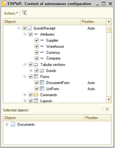
Fig. 513. Standalone configuration content
According to the figure, you can define availability of the following objects in the standalone configuration:
-
Configuration objects. A standalone configuration can include all configuration objects supported by 1C:Enterprise mobile platform.
-
Configuration object attributes, tables, and table attributes.
-
Configuration object forms, commands, and templates.
When setting up a standalone mobile client, the developer can specify which system server will be primarily used to operate with a particular object. To set it up, specify the object usage priority. Priority can be assigned to a standalone configuration object as follows:
-
For the following configuration objects:
-
Common modules
-
Exchange plans
-
Event subscriptions
-
Common forms
-
Common commands
-
Settings storages
-
Constants
-
Catalogs
-
Documents
-
Document journals
-
Enumerations
-
Reports
-
Data processors
-
Charts of characteristic types
-
Information registers
-
Accumulation registers
-
-
For configuration object forms.
-
For configuration object commands.
Priority can be assigned in the column of the same name and have the following values:
-
Main server. In this case, 1C:Enterprise attempts to access an object using the main server of the system.
-
Standalone server. In this case, 1C:Enterprise attempts to access a configuration object using the standalone server of the system.
-
Auto. This value is interpreted as Main server for type-defining configuration objects and as a value of a type-defining object if an object subordinate to a type-defining object is described.
If the Standalone server priority is assigned to a configuration object (for example, the Goods catalog), while the Auto priority is specified for an item form of this catalog, the Standalone server priority will be used for such item form on an actual mobile device. If the priority value for the Goods catalog is changed to Main server, the form priority will be changed by default.
The Data exchange column is intended to include the configuration object in automatic data exchange with the standalone configuration. You can change the value of this column after selecting an exchange plan in the Standalone configuration exchange settings dialog box. You can change the Data exchange column only for the entire object, and specify that changes to objects of this type will be recorded by the exchange plan for automatic exchange between the main and standalone infobases. If this checkbox is enabled, the following settings become available:
-
Autoregistration. Allows you to set up automatic registration of changes to an object in an exchange plan when the object is changed. If the checkbox is cleared, the object must be registered in the exchange plan using the RecordChanges() method of the exchange plan manager. This property is completely similar to the Autoregistration property of the exchange plan.
-
Code/Number adjustment. Allows you to specify what will happen to the number or code of a configuration object if the code or number uniqueness is configured for the object code or number, and duplicate codes or numbers are created during data exchange between the standalone and main infobases. If this property is set to Do not correct, nothing will be changed. It is recommended that you set this up if the object code or number is public information, for example, it is communicated to the client. If the property is set to Correct, when writing an object to the infobase, the number will be corrected according to standard rules: for a text number, an index will be added, and for a numeric number, the maximum value of the code or number will be determined and increased by 1.
If a metadata set defined for the standalone configuration is incomplete, this can cause conflicts in standalone mode. The said conflicts are settled as follows:
-
If missing metadata is used in standalone configuration objects, instead of links to the said objects, external links are used in the following standalone configuration areas:
-
Configuration object attributes
-
Common attributes
-
Owner standard attribute
-
Constants
-
-
If references to missing configuration objects are used in other system features, they will be deleted from the following:
-
Configuration and subsystem command interface
-
Subsystem components
-
Access rights role components
-
Exchange plan components
-
Filter criterium kind and components
-
Catalog and document characteristics
-
Register records
-
Document journal components
-
In addition to manual selection of objects included in the standalone configuration, the following commands are available in the dialog box intended to manage standalone configuration components:
-
Include all makes all main configuration objects part of a standalone configuration.
-
Exclude all. Excludes all objects from the standalone configuration.
-
Find related. This command is available for the main configuration object included in the standalone configuration. It selects main configuration objects used as attribute kinds in the selected configuration object. After completion, a dialog box with all respective objects is displayed. All the objects are selected. If the list responds to your needs, click OK to add it to the standalone configuration.
If the command is executed recursively, both configuration objects used directly in the current object and those available in the objects being used will be selected. If the command is not executed recursively, only objects used in the object for which this command is executed will be selected.
- Select all related. This command is available only if there is at least one object included in the standalone configuration. In this case, the Find related command is executed for each object in the standalone configuration. As a result, a dialog box with all selected objects is displayed.
See also:
- Data exchange during runtime (see Data exchange during runtime).
28.6.3. Defining a server during a call
With the mobile client in standalone mode, you can use two application back ends at the same time: standalone server and main server. When a call is made, the system analyzes certain parameters and selects a server to be used based on the analysis results. The system analyzes the priority of use of a certain object and selected operation modes of the client application. This analysis is performed both for an explicit (for instance, when common module server method is called) and implicit server call (for instance, when a form is opened).
If a server call is initiated in the client application, the server is selected when the call is made. If further server calls are made inside such server call, the server is not changed. Consider some example that demonstrate such behavior.
For example, there is a catalog form called Goods whose priority of use is set to Standalone server. There is a common server module called SM1 whose priority is set to Main server. There is another server module called CM2that is not included in the standalone configuration.
Let us find out which server will be used when various actions are performed:
-
The client application opens the Goods catalog form. Since the Standalone server priority is selected for this form, the form will be opened using a standalone server. Data to be displayed by that form is received from the standalone server, too.
-
If any (context or non-context) form module server method is called in the Goods catalog item form, the method will be executed on the standalone server.
-
If the SM1 common module method is called in the Goods catalog item form from the client method of form module, the main server is called or an exception is thrown. The call is executed if the standalone mobile application is connected to the main server, since the SM1 common module has the Main server priority.
-
If the SM1 common module method is called from the server method of the Goods catalog item form, the standalone server will be used. This is due to the fact that a server call made from a server call uses a server which is selected for the first server call (standalone server in the example above).
-
If a client method attempts to call the SM2 common module method in Goods catalog item form, similarly to the SM1 common module, the call will be made only if connection is established. This is due the fact that the SM2 common module is not included in the standalone configuration.
Despite everything mentioned above, you might need to change a server used to make a call. 1C:Enterprise allows you to do that upon any of the following:
-
You need to call a server method of the main server from a method which is executed on the standalone server. In this case, use the MainServer global context property. If this property is used, common server modules of the main server are accessible on the standalone server. In this case, the call looks as follows: MainServer.ServerCommonModuleName.CommonModuleMethodName().
-
On the client application side, you need to make a server call which uses either the main or standalone server irrespective of current parameters. To do this, use the following global context methods: SetUsedServer() or SetPreferableMainServerUse() (for details, see Switching between standalone/main servers).
-
A client application form has an attribute whose type is not included in the standalone configuration. In this case, when you open the form, the main server is used regardless of the server used to open the form where the attribute is displayed.
28.6.4. Standalone mobile application form
When you develop an application form to be used in the mobile client with standalone mode, note general distinctive features of that form on a mobile device and in the mobile client with standalone mode.
These distinctive features include:
-
Changes in the form item behavior when the main server is unavailable.
-
The possibility to reopen the form if the main server availability changes.
If the main server availability changes when an open form is used, system behavior will depend on a server selected to open the said form:
-
You can define a server from which the form is opened using the UsedFormServer property of the client application form.
-
A form is opened from the main server:
-
The form becomes unavailable.
-
The OnMainServerAvailabilityChange form event is called.
-
The Close command remains available for the form. If a form has a similar form in the standalone configuration, the Open offline command becomes available.
-
-
A form is opened from the standalone server:
-
Behavior of items depends on the value of the OnMainServerUnavalableBehavior form item property. The property can take the following values:
-
MakeInaccessible. Items with this property value are disabled as soon as the main server becomes unavailable.
-
DontChangeBehavior. Items with this property value remain available. When items related to an external reference are accessed, their behavior is defined by the standalone configuration. Standard selection processing will result in an error. However, standard processing can be redefined.
-
Auto is interpreted as:
-
MakeInaccessible for items related to an external reference.
-
DontChangeBehavior for the other items.
-
-
-
If you click Open offline (or call the ReopenFromOtherServer() method) in the form interface, the following operations are performed:
-
For the current form (where the button is click ed), the BeforeReopenFromOtherServer event handler is called. All parameters used to open the current form are passed to the event handler. The developer can modify the list of parameters. If the Cancel parameter is set to True when you exit the event, the form will not be reopened.
-
Another (standalone) form is created. Moreover, all server events are triggered for such form.
-
The OnReopenFromOtherServer event handler is called for the newly created form. The reopened form and filling parameters are passed to the event handler. If the StandardProcessing parameter of the event handler is set to True, the platform transfers data from the previous form to the new one based on the value of the FillParameters parameter. If the StandardProcessing parameter is set to False, the developer must manually transfer data from the previous form. To generate a list of copied attributes, use the OnReopenFormFromOtherServerFillParameters object. To fill data in the newly created form based on the data from the previous form, use the FillOnReopenFromOtherServer() method.
-
The OnOpening event handler is called in the newly created form. All the other events are also called according to the form opening protocol.
-
The state of the previous form depends on its opening mode and location:
-
An independent form is closed as soon as the newly created form is opened. The OnClose event handler is called. The BeforeClose handler is not called. If the CallbackDescriptionOnClose property is set for the previous form, its value is passed to the new form. A notification is called as soon as the new form is closed.
-
The locking form is closed as soon as the new form is closed. The OnClose event handler is called. The BeforeClose handler is not called.
-
If a form is placed on the home page, it remains there. The new form will be opened in independent mode.
-
Before opening a form, remember that:
-
The form owner and form opening parameters remain unchanged.
-
Attribute values of the following types are not transferred:
-
Chart
-
Spreadsheet document
-
Planner
-
-
Data of the following types is transferred only if it is fully imported to RAM:
-
Table
-
Value list
-
Value table
-
Value tree
-
28.6.5. Data exchange during runtime
28.6.5.1. General information
The mobile client with standalone mode must regularly perform data exchange between the main and standalone parts of the application. This is necessary to keep the data used up-to-date. Synchronization is required during system runtime:
-
Data from the main infobase must be transferred to the standalone infobase. This data must be transferred to the extent sufficient to fill standalone configuration object data.
-
Data from the standalone infobase must be transferred to the main infobase: This is the data saved in the infobase when the mobile application runs in standalone mode.
In terms of synchronization, we recommend that you consider both application parts (standalone and main infobases) as separate nodes of the data exchange mechanism supported by 1C:Enterprise. This way, data exchange requirements are applied to a well-known and completed infrastructure:
-
To register changes, an exchange plan is used. An exchange plan cannot participate in a distributed infobase.
-
To transfer data between the standalone and main parts of a single infobase, a standard message infrastructure or standard tools are used to access the list of registered changes.
Make sure that the exchange plan contains objects included in the standalone configuration. The main infobase must include a respective exchange plane item for each infobase of the standalone mobile application.
Therefore, the general procedure is as follows:
-
The first startup of the mobile client with standalone mode is always performed with connection to the main server.
-
When first launched, the mobile client with standalone mode gives a command to the main server to create a standalone infobase for the mobile client. During the infobase creation, the application cannot switch to standalone mode like a regular mobile client. The operations performed on the server:
-
Creating a standalone infobase for a mobile application.
-
Creating an exchange plan node in the selected exchange plan of the main infobase (if necessary).
-
Creating an exchange node related to the main infobase in the standalone infobase.
-
Initial filling of the standalone infobase using data from the main infobase.
-
-
Once the standalone infobase is created, it is passed to the mobile application. You are prompted to restart the mobile client to start working in full mode and be able to switch to the standalone mode and back.
-
Data is regularly synchronized between the main and the standalone infobases when operating. The exchange intensity depends on the standalone configuration settings.
Let's look at how it works in more detail.
To set up data exchange for the standalone mobile client:
-
Create an exchange plan. It will be used to register edited objects. In the standalone configuration setting form, open the Exchange setup dialog box, and specify the plan in the Exchange plan field. After that, you can specify automatic data exchange parameters. The setup includes two parts:
-
Setting up the exchange plan:
- In the standalone configuration settings, specify the objects which will be included in the standalone configuration and whose changes in data will be recorded. Use the Data exchange column.
- Set automatic object registration for data exchange with the mobile client as required (the Autoregistration column).
- Specify how conflicts of object numbers or codes are to be resolved upon the exchange (the Code/Number adjustment column).- Setting up parameters of automatic exchange between the main and the standalone infobases:
- Exchange when written. Indicates that data exchange must be performed once an object included in the exchange plan of the Exchange plan property is written.
- Exchange period. Indicates a time interval of exchanging data between the standalone and the main infobases.
- Items in transaction. Indicates how many changed objects are to be processed within one data receipt transaction. If you want to write more objects than specified in the property, multiple transactions will be generated. The parameter is similar to the <span class="doc-term">TransactionElements</span> parameter of the <span class="doc-term">WriteChanges</span>() method of the exchange plan manager.
- The <span class="doc-interface">Delete</span> unused nodes automatically in XX days property indicates that the system will automatically delete an exchange plan node if it has not been used for the specified number of days. Exchange time analysis uses the <span class="doc-term">ExchangeDate</span> property. It is filled only for the exchange plan used for exchanging data with mobile clients in standalone mode.-
Implement one of strategies for initial generation of the standalone infobase.
-
Implement one of strategies of regular data exchange between the standalone and the main infobases.
The developer can use various exchange plan module events to manage data export to the standalone infobase. There are different lists of events for creating the standalone infobase and synchronizing information.
A new distributed infobase node is created if the mobile client connects to the main infobase on behalf of a user who has no node yet (or it is deleted). In this case, handlers of the following exchange plan item events are called:
-
OnAutoCreateNewNode. The event is called once a new exchange plan item is created but not written yet. All standard attributes of the item are filled by the time you call an event handler. The Code attribute is equal to:
-
The text exchange plan code is the value of the Name property of an infobase user who runs the mobile client with standalone mode. If such code already exists, the code will be modified in the standard way.
-
Digital exchange plan code is the maximum value among all exchange plan codes increased by 1.
-
The name of the exchange plan is filled with the FullName property value of the infobase user.
If, upon exiting the handler, the Cancel parameter is set to False, the exchange plan node is saved in the infobase and the standalone infobase creation continues. If the Cancel parameter is set to True, a standalone infobase is not created, and the mobile client operates without attempting to create a standalone infobase.
- BeforeCreateInitialImage. This event is called before the standalone infobase image creation begins. The OnlyRecorded parameter is passed to the handler. This parameter controls the possibility to transfer all data from the main database to the standalone database (the False value) or only the data registered for transfer (the True value). This setting controls the system behavior after the event handler is completed.
To write some specific data (for example, not recorded by the exchange plan, but needed on the standalone side) to the initial image, use the same handler. To do so, use the DataExchangeStream parameter. The DataExchangeStream.Write() method places an object to be written to the standalone infobase right away.
Thus, after the BeforeCreateInitialImage event handler completion, the objects that were written using the exchange data stream will be placed in the initial image, and processing of all objects of the main infobase that need to be placed in the initial image will begin. The list of objects is determined by the OnlyRecorded parameter value. You can continue filtering objects in the OnSendDataToSlave event handler.
- OnSendDataToSlave. A regular event that occurs when exchanging data using a distributed infobase.
During regular data exchange, a standard set of events is used to accompany data exchange. The data exchange can be initiated as follows:
-
By starting the mobile client on a mobile device.
-
By automatically starting exchange at the interval specified in the exchange settings of the standalone configuration (the Exchange period parameter).
-
When writing a data object, if the object is s part of an exchange plan with a standalone configuration and the Exchange on writing option is specified in the exchange settings of the standalone configuration.
-
Using the DataExchangeWithMainServer.ExecuteExchange() method.
After the exchange is completed and any data was passed, the AfterExchangeDataWithMainServer event handler of the application module will be called. The handler will receive the flag of displaying notifications about the exchange completion and a date and time of the last successful data exchange as parameters. For an exchange in an active application, the exchange date will correspond to the current time.
28.6.5.2. Data exchange interval
Let's take a closer look at the data exchange frequency. There are two time intervals used in data exchange. These intervals work separately from each other.
The first time interval is set by the Exchange period and Exchange when written properties of the standalone exchange plan settings. These settings are used when the application is active (the user operates with the application on the mobile device screen). In this case, the exchange is performed at time intervals specified in the Exchange period property. If the Exchange when written checkbox is set, the Exchange period time interval begins after recording any infobase object participating in the exchange. When such exchange is performed, all handlers of the exchange plan module (server handlers) and the AfterExchangeDataWithMainServer event handler of the application module (client handler) are triggered.
If the application is switched to background mode or the user logs out of a specific application to the list of applications of this mobile application, the exchange interval stops working. In this case, the exchange takes place every 15 minutes. This interval cannot be configured by the developer, but can be changed by the mobile operating system according to its internal algorithms. In this case, all server exchange handlers (exchange plan module) will be triggered, but the client handler of the application module will not be called, since the client application is not running. However, when the client application starts, the event handler of the AfterExchangeDataWithMainServer application module will be called if at least one data exchange was performed in the background. In this case, the value of the ExchangeDate formal parameter of the handler will be the date and time of the last non-empty data exchange performed in the background.
Note that background exchange is performed in turn for all infobases registered in the application. To enable background exchange on Apple devices, use iOS version 13 or later. On Android, background exchange is supported even if the mobile application is not running on the device.
28.6.5.3. Creating initial standalone infobase image
There are several options for generating the initial image of a standalone infobase. The given list of options is not exhaustive, but is intended only to describe some typical cases:
-
Option 1:
-
No data filtering is used.
-
The initial image contains all the data from the main infobase.
-
You can use this option if all infobases of standalone mobile clients are identical to the main infobase.
-
-
Option 2:
-
Objects to include in the initial image of the standalone infobase are filtered in the OnSendDataToSlave event handler.
-
The initial image will contain all the data from the main infobase.
-
This option can be used if minimal data filtering is required when generating the initial image. The initial image must include most of the data from the main infobase.
-
-
Option 3:
-
Only objects registered in the exchange plan are included in the initial image of the standalone infobase. For this, set the OnlyRecorded parameter to True in the BeforeCreateInitialImage event handler. All necessary data is registered in the exchange plan in the same handler. For this, use the RecordChanges() method of the exchange plan manager.
-
The initial image contains only registered data of the main infobase.
-
This option can be used in cases where the data to be transferred to the initial image of the standalone infobase is significantly less than the total volume of data in the main infobase.
-
-
Option 4:
-
Only objects registered in the exchange plan are included in the initial image of the standalone infobase. For this, set the OnlyRecorded parameter to True in the BeforeCreateInitialImage event handler. However, since a new exchange plan node has just been created, there is no registered data object for this node. Thus, use the DataExchangeStream parameter of the initial image creation event handler to write the data, which must be passed to the initial image, manually.
-
This option can be used when data to be transferred to the initial image of the standalone infobase is significantly less than the total volume of data in the main infobase and no additional data transformations are required.
-
-
Option 5:
- It is a combination of two previous options (3 and 4). In this case, registration of the necessary elements in the exchange plan is combined with direct recording of other objects in the handler.
28.6.5.4. Data exchange methods
You can use several options to regularly exchange information between the standalone and main infobases. The given list of options is not exhaustive, but is intended only to describe some typical cases:
-
Option 1:
-
No data filtering is used.
-
All data from both infobases is included in the exchange.
-
You can use this option if all infobases of standalone mobile clients are identical to the main infobase.
-
-
Option 2:
-
Data filtering during exchange is performed in the OnSendDataToSlave/OnSendDataToMaster event handler.
-
Allows you to implement almost any filtering scenario.
-
-
Option 3:
-
In the exchange plan, automatic object registration is disabled.
-
To include exchange in the package, use forced registration in the object or the BeforeBeginSendDataToSlave/ BeforeBeginSendDataToMaster event handler.
-
See also:
-
Setting up the standalone configuration content (see Standalone configuration content).
-
Using exchange plans (see General information).
28.6.6. Switching between standalone/main servers
When you use the mobile client with standalone mode, both standalone and main servers can run at the same time. The application is able to define whether the main server is available or not and call the main server from the code executed on the standalone server side. However, it cannot call the standalone server from the code executed on the main server side.
To determine availability of the main server, use the MainServerAvailable() global context method.
If the standalone server is used, you can call a method of the main server, which is accessible in the common server module of the main server. To do it, use the MainServer global context property. The call looks as follows: MainServer.CommonModuleName.MethodName(). If the main server is unavailable, an exception is thrown.
If the client part of the standalone mobile application needs to call a server, the call is made according to the standalone configuration priorities. However, the system allows you to explicitly specify the server to be used. To do it, use the SetUsedServer()method.
This method operates in the following way:
-
If a certain server is explicitly specified when the method is called, this server is used. Explicitly specified servers are defined by values of the UsedServer system enumeration.
-
If Undefined is specified when the method is called, the server call mode before the latest setting of the used server is set.
-
When you exit the method where used server is changed, the server used before you enter the method is set.
Consider an example:
SetUsedServer(UsedServer.Main);
// line 1
SetUsedServer(UsedServer.Standalone);
// line 2
SetUsedServer(Undefined);
// line 3After line 1, the main server is selected. After line 2, the standalone server is selected.
After line 3, the server used before the recently defined server is selected. So, the main server will be used because the second-to-last server (line 1) is the main one.
To get the used server, use the GetUsedServer() method.
Explicit setting of a used server using the SetUsedServer() method is applied until the method where the server was set is completed. This is not always convenient. Sometimes you might need to switch the mobile application to the main server mode. For example, when initial initialization of standalone data is not completed. To specify that the main server is preferable for use, you can use the SetPreferableMainServerUse() global context method. This method has two important distinctive features:
-
The method is applied to the entire application, not only to the current method.
-
The SetPreferableMainServerUse() method is applied only if the SetUsedServer() method has not been called in the current stack yet.
In this case, do the following:
-
Define that the first startup of the standalone mobile application is performed. Enable preferable use of the main server.
-
Start a background job for initial filling of standalone data. Within this job, use the SetUsedServer() method to ensure that the filling procedure of standalone data uses the standalone server.
-
After data is filled, disable preferable use of the main server.
28.6.7. Standalone mobile application specifics
28.6.7.1. Mobile device configuration update
The mobile client with standalone mode cannot be initially started in standalone mode. For the first startup, you need to have an interrupted communication channel to connect to the main infobase. It is required to import the standalone configuration.
Further, upon each startup of the client application and establishment/reestablishment of connection between the mobile application and main server, the standalone configuration is checked for available updates. You can observe one of the following scenarios:
- An update is found when the client application is started, before its actual use:
-
The standalone configuration update file is automatically downloaded to the device.
-
The standalone infobase configuration is updated using the downloaded configuration.
-
Before connection to the main server is established, the client operates in standalone mode and is able to connect to the main server:
-
The user is prompted to confirm configuration update.
-
If the user confirms the update, the standalone configuration update file is downloaded to the mobile device, and the client application is restarted. After that, the standalone infobase is updated using the downloaded configuration.
-
If the user declines the update, the client application continues operation with the previous standalone configuration version with no ability to connect to the main server (in standalone mode).
-
-
If a configuration update is found upon another connection to the main server (with disabled standalone mode), the current session is closed, and the previous operation scenario is applied.
28.6.7.2. External references
External references are references to objects not included in the standalone configuration. However, such references are used in standalone objects. Any references to configuration objects can be used as external references, including references to objects unavailable on a mobile device. Any actions with standalone references (receiving attribute values, receiving objects, and so on) are not supported on mobile devices. In fact, external references are used to display real data in respective form fields. As a result, the user does not have to be worried about data "loss".
If data being an external reference is displayed in a form field:
-
In case of no connection to the main server:
-
This field becomes inaccessible.
-
Reference presentation is cached as soon as connection is reestablished.
-
If no external reference presentation is saved on a mobile device, a message about data unavailability is displayed instead.
-
-
In case of connection to the main server:
-
The reference is available for further use.
-
The main server is called for that.
-
28.6.7.3. Command interface
If a command is not included in the standalone configuration, it will be unavailable in standalone mode. If a command is included in the standalone configuration, its availability in standalone mode will be defined by the Behavior in case the main server is not available command property. If the property is set to Auto, it is interpreted as Do not change behavior. If property editing is unavailable for the command, Do not change behavior is used.
28.6.7.4. Users
No user operations are supported by the mobile client with standalone mode. When the application is started, username and password are requested. Authentication is performed by the main server. If a user different from the one specified upon initial authentication (when the infobase is created) is specified upon following application startups, an error occurs. Therefore, if the mobile device is used to operate a single main infobase by two or more users, each of them needs to have a separate infobase (application) on the mobile device.
If a user that signed in to the main infobase changes their password, the standalone infobase is notified about it only after successful authentication on the main server.
28.6.7.5. History
History is stored both on the main and standalone infobase server. If a mobile device is granted access to the main server, history is saved in both infobases. If a mobile device is not granted access to the main server, history is saved in the standalone infobase only. As soon as access to the main server is granted, history versions are merged and saved in both infobases.
28.6.7.6. Favorites
Favorites are stored both on the main and standalone infobase server. If a mobile device is granted access to the main server, favorites are saved in both infobases. If a mobile device is not granted access to the main server, favorites are saved in the standalone infobase only. As soon as access to the main server is granted, favorites are merged and saved in both infobases.
28.7. Mobile device interaction during development
28.7.1. General information
You can install mobile applications on mobile devices in several ways:
Via App Store (https://itunes.apple.com/ru/genre/ios), Google Play (https://play.google.com/) or Microsoft Store (https://www.microsoftstore.com). This method is used to distribute public versions of mobile applications.
A mobile application prepared for publication is approved and published according to the rules of the respective application store. Details of this process are not covered in this guide.
- Via the mobile 1C:Enterprise version for developers. This method is used only for mobile application development. This method is described below.
To start using the mobile 1C:Enterprise version, do the following:
-
Install the mobile 1C:Enterprise version for developers on the mobile device.
-
Publish the mobile application on a web server.
-
On the mobile device, create an infobase (application) based on the published mobile application.
After that, you will have a ready-to-use infrastructure for mobile application development and running on the mobile device. The system can be configured in such a way that the configuration update will cause the mobile 1C:Enterprise version for developers to automatically update the configuration on the mobile device.
Further, each action will be reviewed in more detail.
28.7.2. Installing developer tools
28.7.2.1. General information
Depending on the configuration being developed, the developer may need different developer tools:
-
To develop a mobile application, the developer mobile platform is required.
-
To develop a mobile application, the developer mobile client is required.
-
To develop a mobile application with standalone mode, the developer mobile client with standalone mode is required.
The generation algorithms of developer tools are the same for both the mobile platform and the mobile client. Differences are present only in the file names used in different situations. To prepare the mobile platform for iOS developers, get the prjios.zip file from the distribution package of the mobile 1C:Enterprise version (the mobile.zip file). For the mobile client, use the prjios_client.zip file. For the mobile client with standalone mode, use the prjios_standalone.zip file.
The table shows respective file names for various client applications of the mobile 1C:Enterprise version:
| Mobile operating system Client application kind | File name |
|---|---|
| Android | |
| Mobile platform | 1cem-arm.apk 1cem-arm64.apk 1cem-x86.apk 1cem-x86_64.apk |
| Mobile client | 1cem-client-arm.apk 1cem-client-arm64.apk 1cem-client-x86.apk 1cem-client-x86_64.apk |
| Mobile client with standalone mode | 1cem-standalone-arm.apk 1cem-standalone-arm64.apk 1cem-standalone-x86.apk 1cem-standalone-x86_64.apk |
| iOS | |
| Mobile platform | prjios.zip prjios_sim.zip |
| Mobile client | prjios_client.zip prjios_client_sim.zip |
| Mobile client with standalone mode | prjios_standalone.zip prjios_standalone_sim.zip |
| Windows | |
| Mobile platform | 1cem-arm.appx 1cem-x64.appx 1cem-x86.appx |
| Mobile client | 1cem-client-arm.appx 1cem-client-x64.appx 1cem-client-x86.appx |
| Mobile client with standalone mode | 1cem-standalone-arm.appx 1cem-standalone-x64.appx 1cem-standalone-x86.appx |
In this table:
-
–arm, –arm64, –x86, –x64, and –x86_64 denote the architecture of a processor in use.
-
-sim denotes a version to be used in the device emulator (applicable to iOS development only).
28.7.2.2. For Android
To develop a mobile application on Android, fulfill the following requirements:
-
Install Android Studio on your computer (http://developer.android.com/studio/index.html). For the developer platform to work, Android SDK Platform-tools version 26 or later must be installed on the computer.
-
Use Android Studio to check whether all the required components are installed. To do this, in the start window, select Configure – SDK Manager. For convenience, you can select the Show Package Details checkbox in the opened window.
-
On the Platforms SDK tab, you can check the availability of required Android SDK versions.
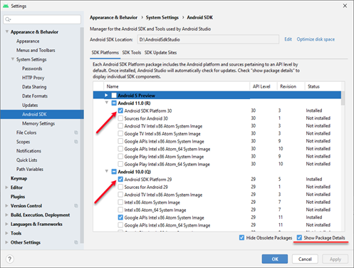
Fig. 514. Selecting Android SDK versions
- On the SDK Tools tab, specify Android SDK Build-Tools and Android SDK Platform-Tools. We recommend that you install all the Tools and SDK consistently. In this case, all versions will be compatible with each other. We do not recommend that you install incomplete versions such as rc, beta, and so on. The builder will not accept these versions as suitable for use. For example, fig. 515 shows that Android SDK Build-Tools can be updated to version 31.0.0 rc5. Do not install this update!
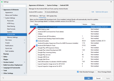
Fig. 515. Selecting tool versions
-
After the settings have been configured, click OK or Apply to start the installation process of the required components. Before starting the installation process, Android Studio will ask to confirm the installation of the selected components (indicating the entire list).
-
The computer must have one free USB port used to communicate with the mobile device.
-
You need a mobile device on Android that meets the system requirements.
To install the mobile 1C:Enterprise version for developers on a mobile device on Android, do the following:
-
In the settings of the mobile device, select the following checkboxes:
-
Unknown sources
-
USB debugging
-
-
Download the USB driver for mobile devices from the manufacturer's website and install it on your computer.
-
Attach the mobile device to the computer.
-
Using the Windows command line interpreter, execute the command:
Example for ARM platform:
%ANDROID_SDK%/platform tools/adb.exe install –r "/1cem-arm.apk"Example for x86 platform:
%ANDROID_SDK%/platform tools/adb.exe install –r
"<Platform directory>/1cem-x86.apk"Where Platform directory is the directory in which the corresponding file with the mobile 1C:Enterprise version is located. If the mobile 1C:Enterprise version is already installed on the mobile device, this command will reinstall it.
-
The mobile 1C:Enterprise version will be passed to the mobile device, and its icon will appear in the list of installed applications.
-
The mobile device can be disconnected from the computer. After that, the system can be started by tapping the 1C:Enterprise icon in the list of mobile device applications.
To install the mobile 1C:Enterprise version for developers, you can use the following Designer command:
-
For the mobile platform: Main menu – Configuration – Mobile application – Use Android Debug Bridge – Install mobile platform.
-
For the mobile client: Main menu – Configuration – Mobile client – Use Android debug bridge – Install mobile client.
In this case, you will need to perform additional setup of Designer (for details, see Mobile application). The mobile platform can be installed either on a physical mobile device attached to a computer or on a device emulator created in Android Virtual Device Manager. Android Virtual Device Manager can be started from Android Studio: Main menu – Tools – Android – AVD Manager.
28.7.2.3. On iOS
To develop a mobile application for iOS, fulfill the following requirements:
-
You can use a mobile device only from an Apple computer (hereinafter referred to as Mac) with OS X 11 or later.
-
A Mac computer must have one free USB port for connection with the mobile device.
-
On this computer, install the Xcode development tool version 12.5 or later (https://developer.apple.com/xcode/).
-
Register in iOS DeveloperProgram (https://developer.apple.com/programs/ios/).
-
You also need a mobile device on iOS that meets the system requirements.
To install the mobile 1C:Enterprise version for developers on a mobile device on iOS, do the following:
-
Install an Xcode package on a Mac computer.
-
Start Xcode.
-
Add a developer account to Xcode:
-
Open Xcode settings (Xcode - Preferences) on the Accounts tab.
-
In the lower left corner of the form, click +. In the list of account types, select Apple ID and click Continue. In the opened dialog box, enter a username and Apple ID password for the developer account.
-
After the account is added, development teams linked to the added account become available in Xcode.
-
Attach the mobile device to the Mac computer.
-
Unpack the file with the required project of the mobile 1C:Enterprise version on the Mac computer.
-
Open the mobile 1C:Enterprise version for developers in the Xcode system. To do it, double-click the 1cem.xcodeproj file or select the 1cem.xcodeproj file by clicking File – Open.
-
In the project settings, select theSigning & Capabilities tab. In the Team field, select one of the development teams that became available after adding the developer account to Xcode.
-
In the Bundle Identifier field, enter the application ID.
-
Open the Organizer tool by clicking Window – Organizer.
-
In the left panel of the opened window, select the attached phone (highlighted in green).
-
In the bottom panel, select Add to Portal.
-
The Organizer tool will request required phone certificates and the provisioningprofile from the Apple website and automatically install them on the phone. You will need to enter the developer password received during registration in the iOS Developer Program.
-
Click Product – Edit Scheme… to open a dialog box where you can set up the current startup scheme. In the opened dialog box:
-
In the Scheme property, select 1cem.
-
In the Destination property, select the attached phone.
-
In the Build configuration property, select Release.
-
Click OK.
-
Start the project by clicking Product – Run.
-
The mobile 1C:Enterprise version will be transferred to the mobile device, started, and its icon will appear in the list of installed applications of the mobile device.
The mobile device can be disconnected from the Mac computer. After that, start the mobile 1C:Enterprise version by clicking the 1C:Enterprise icon in the list of mobile device applications. If the mobile 1C:Enterprise version for developers is running on Xcode at the moment of disconnection, it is closed.
28.7.2.4. On Windows
To develop a mobile application for Windows, fulfill the following requirements:
-
Operation with mobile devices is supported only on computers running Windows 8.1 or later.
-
You need to have a Microsoft account (https://login.live.com/).
-
For operation, you need a device on Windows (tablet or computer with a touch screen) that meets the system requirements.
To install the mobile 1C:Enterprise version for developers on a device running Windows, do the following:
-
Copy the distribution file of the mobile 1C:Enterprise version to the device (mobile.zip).
-
Extract the 1cem.cer certificate file from it.
-
Install the certificate in the Trusted people store on the local computer.
-
Extract a file with the required distribution package of desired architecture from the distribution file of the mobile 1C:Enterprise version.
-
Start PowerShell as the administrator (system administrator rights are insufficient).
-
Execute the following command:
Show WindowsDeveloperLicenseRegistrationIn the opened window, specify the Microsoft account information.
- Execute the following command:
Add AppxPackage <Directory>/<file
name>.appxWhere:
-
<Directory> is the directory where the mobile 1C:Enterprise version for developers is placed.
-
<file name> is the name of the platform version to be installed (for details, see General information).
-
After that, you can start the system by tapping the 1C:Enterprise icon in the list of applications.
28.7.3. Publishing a mobile application on a web server
28.7.3.1. General information
Note. Important. In the mobile client, the actions listed in this section are not required.
For the mobile application to be available to the mobile platform, you must publish it on a web server. The publication process is divided into two parts:
-
Infrastructure preparation for operation and initial import of the mobile application configuration (performed once).
-
Mobile application configuration update in the prepared infrastructure.
To prepare the infrastructure, click Configuration – Mobile application – Publish…. In the opened dialog box, select the Create a virtual directory on the web server checkbox. If the checkbox is not selected, the Name and Directory attributes will be unavailable, and clicking Publish will not create a virtual directory on the web server.
Note. Important. Administrative rights are required to complete the publication.
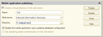
Fig. 516. Mobile application publishing
After that, specify the properties of the virtual web server directory:
-
Name. Defines the name of the virtual directory. This name will participate in the URL configuration of the mobile application to indicate on the mobile device when creating the infobase.
-
Web server. Defines the web server in use. If you are using the Microsoft Internet Information Services web server, you can select the Use operating system authentication on the web server checkbox.
-
Directory. Specifies the physical directory on the hard drive in which the mobile application configuration file will be located as an XML file, and where the virtual directory of the web server will be displayed.
Use the Update mobile application when updating database configuration checkbox to enable/disable automatic update of the mobile application configuration upon database configuration update. If the checkbox is selected, update is performed.
You can also forcibly update the configuration by clicking Configuration – Mobile application – Update published application. If the mobile application is not published when this command is called, the publication dialog box described above will be opened.
Note. Important. The web server publishes the database configuration, not the editable configuration.
To perform the publication, click Publish. This triggers the following events:
-
If the Create a virtual directory on the web server checkbox is selected, a virtual directory is created on the web server.
-
The directory is created on the hard drive where the virtual directory is displayed.
-
We recommend that you export the mobile application configuration to the directory specified in the Catalog attribute of the publication dialog box.
-
The system checks whether the database configuration matches the configuration being edited.
-
If the infobase configuration does not match the configuration being edited, the system prompts you to update the database configuration. However, this operation is optional if the database configuration is the one to be published.
-
The mobile application is checked (see Centralized configuration verification).
-
If there are no errors, the infobase configuration is exported to the file. Otherwise, export is not performed.
The file with the mobile application configuration exported by the Publish... command has a fixed name: 1cema.xml. Search (and update) of this particular file is performed when the Update published application command is executed. When creating a virtual directory, the configuration file (1cema.xml) is set as its (directory) default page. This allows you to specify the URL in abbreviated form in the dialog box for creating an infobase on a mobile device.
The Disable button of the dialog box for mobile application publication cancels the publication. It deletes the virtual directory on the web server and the physical directory.
28.7.3.2. Publication details
A publication directory has the following structure:
-
1cema.xml. Configuration description that contains its name, languages, and required permissions.
-
1Cv8.1CM. File that accelerates the infobase creation process. It contains configuration data.
-
If a configuration has add-ins, the publication directory will have the following directory structure (all directories and files are optional):
-
Android
-
<Add-InName>.xml
-
ARM
-
<AddInName>.so
-
<AddInName>.apk
-
-
ARM64
-
<AddInName>.so
-
<AddInName>.apk
-
-
i386
-
<AddInName>.so
-
<AddInName>.apk
-
-
x86_64
-
<AddInName>.so
-
<AddInName>.apk
-
-
-
iOS
-
<AddInName>.xml
-
Universal
-
<AddInName>.a
-
<AddInName>.dylib
-
-
-
WindowsRuntime
-
<Add-InName>.xml
-
ARM
- <AddInName>.dll
-
i386
- <AddInName>.dll
-
x86_64
- <AddInName>.dll
-
-
If a configuration has several add-ins, the publication directory (in any relevant directory structure) will have unique file sets whose number matches the one of configuration add-ins.
All files created as a result of publication are deemed an integral part of the published configuration. Deletion, relocation, or renaming of files will result in abnormal performance of the published configuration.
To ensure normal operation of the published configuration, make sure that the web server has registered MIME types for the following extensions:
-
Performed by Designer upon publication:
-
.xml. application/xml.
-
.1CM. application/octet-stream.
-
-
Manual registration is required if add-ins must be debugged:
-
.so. application/octet-stream.
-
.apk. application/octet-stream.
-
28.7.4. Starting and restarting mobile platform applications
28.7.4.1. General information
You can start the mobile application directly on the mobile device or from Designer. The mobile 1C:Enterprise version for developers must be installed on the device.
You can start the application from Designer when all the following conditions are met: development is performed on Android and Designer is configured as required (see Mobile application).
28.7.4.2. Restarting a mobile application published on a web server
If the mobile application is started using the mobile platform for developers and theRestart from Designer checkbox is selected in the application (see Modifying application properties), you can restart the mobile application from Designer. You can do it using one of the following main menu commands: Debug – Start debugging – Mobile application: start debugging or Debug – Start debugging – Mobile client: start debugging.
If the configuration has been modified (changed), Designer displays the following question: The configuration you are editing is different from the database configuration. Update database configuration? Select Yes to save your changes.
If you select No, the mobile application will be restarted without updating the configuration.
If the Update mobile application when the database configuration is updated checkbox was selected upon mobile application publication, the published mobile application configuration will be automatically updated.
Add-ins used in the configuration will also be placed in the directory where the virtual directory of the web server is displayed. Only add-in files to be used on Android and iOS will be copied (if they exist in the archive with the add-in).
The mobile application performs an update check upon opening if the Restart from Designer checkbox is selected in the properties of the mobile application on the mobile device. If this checkbox is cleared, update check is not performed upon opening. However, you can perform this check manually (see Modifying application properties).
28.7.4.3. Starting and restarting a mobile application when using Android debug bridge
You can start and restart the mobile application using Designer. You can do it using one of the following main menu commands: Debug – Start debugging – Mobile application: start debugging or Debug – Start debugging – Mobile client: start debugging. To use Android Debug Bridge, Designer must be properly configured (see Mobile application). Besides, the configuration must be published in the file system. In this case, publishing on the web server is optional (see Publishing a mobile application on a web server).
If the configuration has been modified (changed), Designer displays the following question: The configuration you are editing is different from the database configuration. Update database configuration? Select Yes to save your changes.
If you select No, the mobile application will be restarted without updating the configuration.
If the Update mobile application when the database configuration is updated checkbox was selected upon mobile application publication, the published mobile application configuration will be automatically updated.
If you use Android Debug Bridge, the add-ins used in the configuration will also be copied to the mobile device being used. Only add-in files to be used on Android will be copied (if they exist in the archive with the add-in).
After restarting the mobile developer platform, a new configuration will be detected, and you will be prompted to perform the update.
28.7.5. Application debugging
You can debug an application on a mobile device only over HTTP debugging protocol. The mobile application on Android can be started in debug mode directly from Designer via Android Debug Bridge (see Mobile application). The mobile application on iOS or Windows cannot be started in debug mode directly from Designer. For more information on how to set up mobile applications, see Debugging mobile application.
To debug an application, two parameters in the properties of the mobile application infobase are used:
-
Debugging allowed. Indicates whether debugging is allowed in this mobile application.
-
Debugging address. Indicates debug server location if debugging is allowed.
-
The above parameters are ignored if:
-
The infobase is started directly from Designer. In this case, the address of Designer from which the mobile application is started is specified as debug server address. It is applicable only for operation via Android Debug Bridge.
-
The Restart from Designer checkbox is selected for the configuration. In this case, the debug server address is acquired from the mobile application publication.
-
28.7.6. Managing the mobile application for developers
28.7.6.1. Creating an application
To create an application on the mobile platform for developers:
-
Start 1C:Enterprise on your mobile device.
-
Select the Add Application command.
-
In the opened window, enter the URL of the web server where the mobile application is published in the Address field.
-
If necessary, specify the username and password for authorization on the web server where the mobile application is published and tap Import.
-
Specify the name of the application and tap Done.
-
After the window closes, the application will be created.
The list of applications will be skipped, and the application will be immediately started if it is the only one on the list. In this case, to go to the list of applications, select the List of applications command in the main menu of the application.
28.7.6.2. Modifying application properties
Application properties are modified in a special window. Depending on the operating system, access to this command is different:
-
On Android: tap and hold the required application or swipe left. In the opened context menu, select the Change command.
-
On iOS: on the right side of the row with the required application name, tap the picture with the Greater-than sign.
-
On Windows: tap and hold the required application or swipe left. In the opened context menu, select the Change command.
In the opened window, you can change the application properties that were specified upon its creation: application name, configuration location URL, username and password to access the web server where the mobile application configuration is located.
In this window, you can also perform the following actions:
-
Start the mobile application. To do this, tap Open.
-
Check whether a new version of the mobile application configuration is available on the web server. To do this, tap Check for updates. If there is a new version of the configuration, you will be prompted to update the mobile application.
-
To delete the application, tap Delete.
Note. Warning. After the application is uninstalled, infobase data cannot be recovered.
Configure the automatic update and restart of the mobile application in case a new version of the configuration is found on the web server. To do this, change the state of the Restart from Designer checkbox.
Configure debugging availability using the Debugging allowed checkbox and specify the debugger address in the Debugger address field.
The list of applications will be skipped, and the application will be immediately started if it is the only one on the list. In this case, to go to the list of applications, select the List of applications command in the main menu of the application.
28.7.6.3. Uninstalling the application
To delete an application, select the Delete command and confirm your action. Depending on the operating system, access to this command is different:
-
On Android: tap and hold the required application or swipe left. In the opened context menu, select theDelete command.
-
On iOS: tapChange, then tap the picture on the left side of the row with the name of the application to be deleted. After that, tap the Delete button on the right.
-
On Windows: tap and hold the required application or swipe left. In the opened context menu, select theDelete command.
The list of applications will be skipped, and the application will be immediately started if it is the only one on the list. In this case, to go to the list of applications, select the List of applications command in the main menu of the application.
Note. Warning. After the application is uninstalled, infobase data cannot be recovered.
28.7.7. Building a mobile application before publishing it to the application store
To publish a mobile application in an application store, you need to build it using the mobile application builder. The mobile 1C:Enterprise version for developers cannot be published in the application store.
For more information on how to set up and use the mobile application builder, see Mobile Application Builder. For more information on how to publish a mobile application in an application store using a builder, see Publishing in application store (for iOS and Android only). Manual publishing of mobile applications is described in the developer documentation of the respective application store.
28.8. Mobile Application Builder
28.8.1. General information
The mobile application builder is designed to store and compile various mobile application artifacts into a single file suitable for publication in the application store or for direct use on the device. These artifacts include:
-
Application configuration
-
Graphic information
-
Multimedia information
-
Add-ins
-
Mobile 1C:Enterprise version
In the builder, you can build both mobile applications and mobile client applications. In both cases, a single built mobile application allows you to use multiple configurations.
The mobile application builder functions only on Windows. Other operating systems are not supported.
Building is supported for all platforms that support the mobile 1C:Enterprise version. You can also disable building for operating systems not required in each specific case. However, within one operating system, building variability is not supported. This means that all architectures are always built for Android and Windows, and you cannot change this fact.
The building result is:
-
Android: executable files (APK files) for ARM, ARM64, x86, x86-64 architectures, and an application package (AAB file). The application package file is used to publish the application in Google Play Store.
-
iOS: a project file for self-build in Xcode, an executable file (IPA file), and a mobile application for running in the iOS emulator. The possibility of building an IPA file is managed by the setting.
-
Windows: executable files (APPX files) for x86, x86-64, and ARM architectures.
28.8.2. Setting the builder
28.8.2.1. General information
Setting up the builder consists of several stages, the most important of which are setting up building infrastructure parameters and application provider parameters. If any of the setup steps are not completed, the mobile application will not be built.
General setup scheme of the builder:
-
Set up builder parameters using the setup dialog box (see Infrastructure setting).
-
Set up the mobile application provider parameters.
-
Import one or more mobile versions of 1C:Enterprise (see Mobile versions).
-
Import files with provisioning profiles if you plan to use push notifications for iOS (see Provisioning profiles).
-
Import one or more versions of various audio information for mobile applications (see Audio information).
-
Import one or more versions of various graphic information for mobile applications (see Graphic information).
-
Import mobile configurations from which mobile applications will be built (see Configurations).
-
Create the mobile application records.
-
After completing all the steps, you can build mobile applications (see Building the application) and publish them in application stores (see Publishing applications).
28.8.2.2. Infrastructure setting
28.8.2.2.1. General information
The first step is to install the required software suite (build infrastructure) on a computer where applications for mobile devices will be built. Hereinafter, this computer is referred to as build server. The build infrastructure depends on mobile operating systems for which mobile applications will be built.
To specify paths to required components in the builder settings, use the following dialog box: Service – Builder parameter settings. To specify paths on a certain build server, use the Component paths dialog box: Service – Builder parameter settings – Create. This dialog box contains hyperlinks that simplify search for software distribution packages required to create build infrastructure.
Build infrastructure includes the following software packages:
-
Any build:
-
If mobile version 8.3.18 or 8.3.17 is used, JDK version from 1.8 to 13 inclusive is required.
-
Starting from mobile version 8.3.19, the required JDK version is defined by the mobile version parameters.
-
-
Android:
-
Relevant version of Android Studio with SDK installed.
-
SDK versions and required components (Tools, Build tools) that have not reached the release stage (beta, release candidate, and so on) are not supported.
-
The minimum number of used SDK is 26.
-
Starting from mobile version 8.3.19, the required SDK version is defined by the mobile version parameters.
-
-
iOS (if you need to build IPA files):
-
The pscp and plink utilities (version 0.71 or later is required) from PuTTY package.
-
A Mac computer must have an Xcode package version 10.0 or later.
-
Starting from mobile version 8.3.19, the mobile version parameters contain requirements for the plink utility version and specify requirements for an Xcode package version.
-
-
Windows:
-
Windows 10 SDK.
-
If you need to build applications for Windows, the build server must function on Windows 8.1 or later.
-
The Working directory and builder cache parameter specifies the path to the directory that is used to build and store caches of used components. The directory can occupy a substantial amount of hard drive space up to several GB. The directory path must contain only Latin letters. The user on whose behalf the 1C:Enterprise server used for building is running must have full access to the working directory of the builder. It is strongly recommended that you place the working directory of the builder on the build server computer. Forcible cleanup of this directory (between building processes) does not affect building results but affects building duration. However, to optimize disk space usage, the builder can automatically delete all artifact directories that have not been used for over 30 days from the cache directory. So, cache will contain only those artifacts (mobile versions, service data sets, add-ins, and so on) that are regularly used in the current building processes.
The Mobile version distribution auto download directory parameter allows specifying a directory that the builder can use to download a new mobile version of the platform automatically. It is recommended that you create this directory on the hard drive of the build server computer (to speed up import). To execute such import, place the file of a mobile version distribution package (mobile.zip) into this directory. If the mobile version placed into the directory for automatic import is missing in the builder infobase, this version will be imported. The directory for automatic import is checked every two minutes. If this version already exists in the infobase, the version will not be imported. The directory for automatic import is cleaned up within the regular builder cache cleanup. In other words, all files in the directory for automatic import that fall under the mobile.zip mask will be deleted during the next (relative to the time a file with a distribution package is placed to the import directory) background job for cache directory cleanup.
When setting up the builder, remember that the following features (and related settings) are unavailable in the builder of mobile applications deployed in a file infobase:
-
Automatic import of distribution packages for mobile 1C:Enterprise versions.
-
Automatic cleanup of the builder cache directory from obsolete artifacts.
-
Automatic cleanup of the builder database from obsolete artifacts stored in an infobase (see Automatic clearing of artifacts).
28.8.2.2.2. On Android
The required version of Android SDK is determined by the mobile platform version used for building. Starting from mobile version 8.3.19, Android SDK version required for building is specified in the mobile version parameters. For earlier versions, the required version is not controlled by the builder. The behavior is defined by the Gradle scenario used for building.
The mobile application builder supports building only with the Gradle package. Building with Apache ANT is not supported. If you need to build a mobile application based on the mobile version 8.3.10 or earlier, use the mobile application builder version 8.3.18.
Note. Note. Gradle works in online mode only. No consistent Internet connection makes building applications on Android impossible.
In general, the minimum API level that must be installed using the Android Studio package is API 26. If the mobile version contains requirements for the API version used for building, install the API of the required level.
Specify the path to Android SDK in the Android SDK (version 26 or later) field.
See also:
- Information about the mobile 1C:Enterprise version (see Mobile versions).
28.8.2.2.3. On iOS
If you want to build an executable file to run on iOS, select the Build application package (.ipa) on Apple computer checkbox and set access parameters to this computer. To check whether parameters are specified correctly, tap Check connection. If all settings are correct, this will open a window that contains the operating system version of the Mac computer. If the Build application package (.ipa) on Apple computer checkbox is cleared, the building result on iOS will be a project archive for self-building the application using Xcode and a mobile application for operation in the emulator.
To ensure that the Mobile Application Builder can perform any actions on the side of a Mac computer, set up this computer. To do this, follow these steps:
-
Install all available macOS updates.
-
Install Xcode. Get the package here: https://developer.apple.com/xcode/. Xcode version requirements are determined by the mobile version of 1C:Enterprise used to build a certain mobile application.
-
Download and install the Apple Worldwide Developer Relations certificate to the System keychain (http://developer.apple.com/certificationauthority/AppleWWDRCA.cer).
-
Using the Apple developer portal tools, create and install a distribution certificate for the Apple AppStore or for corporate distribution in the System keychain:
-
For that, you need to create a private key via the keychain tools.
-
Note that all private keys and certificates must be located in the System chain.
-
After creating the private key, select Allow all programs to access this object on the Access tab of the key properties dialog box.
-
Using the Accounts tab of Xcode settings, set up a provisioning profile corresponding to the distribution certificate.
-
In the Shared access settings of the Mac system settings, enable the Remote login mode.
-
Get the computer name to be later specified in the mobile application builder settings.
-
Also make sure that IP port number 22 (SSH) of a Mac computer is available for the computer where the server of the mobile application builder is running.
See also:
- Information about the mobile 1C:Enterprise version (see Mobile versions).
28.8.2.2.4. On Windows
With the Mobile Application Builder version 8.3.19 or later, you can build mobile applications that only run Windows 10. You cannot build mobile applications running Windows 8.1 and Windows Phone 8.1. To build a mobile application that will run Windows 8.1 (any variant), use the mobile version 8.3.13 or earlier and the Mobile Application Builder version 8.3.18.
To build a mobile application that will run Windows, download and install Windows 10 SDK. Specify a path to this SDK in the Path to Windows 10 SDK parameter.
28.8.2.2.5. Automatic clearing of artifacts
Note. Note. This feature is not applied if the builder is started in a file infobase.
Since files and built mobile applications of the mobile 1C:Enterprise version occupy a significant amount of space, the infobase can be automatically cleared from outdated versions of both mobile version and built applications. For this, the builder commits the download date of the mobile 1C:Enterprise version and the latest build of the mobile application. After that, the deletion dates are calculated separately for the mobile 1C:Enterprise version files and build results, and all objects whose modification date is earlier than the resulting deletion date are deleted. Object storage time is configured separately for the mobile 1C:Enterprise version files and build result files. This setup is performed using the following parameters:
-
Mobile file storage duration, days. The default value is 180 days.
-
Built version storage duration, days. The default value is 90 days.
If any of the parameters mentioned above is set to 0, automatic deletion will not be used for respective objects.
If the deleted object is required again in the builder:
-
You can download files of the mobile 1C:Enterprise version again from the mobile*.zip file of the respective version.
-
Mobile application files will need to be rebuilt.
28.8.2.3. Setting provider parameters
28.8.2.3.1. General settings
After the infrastructure is set up, configure the provider parameters of the mobile applications to be built. To do this, open the Service – Provider parameters setting dialog box.
First, specify the mobile operating systems for which applications will be built in the builder. To do it, use the Build new applications of this provider checkbox group. Selecting a checkbox opens a tab with parameters for the corresponding operating system.
28.8.2.3.2. Android parameters
Specify the ID prefix of the mobile application. In the future, the full ID of the mobile application will be generated from the prefix, which is specified in the provider parameters and application ID.
To build a mobile application, create or import an application signature key (the Application signing key group). Use this key to sign the built application as an APK file. The application signature key never changes during the entire application lifetime. The signature key is stored as a Java keystore, which is a binary file that serves as a store for certificates and private keys. The application signature key is confidential and must be kept secret. To operate with the application signature key, use the following commands:
-
Set an application signature key. Imports the existing signature key located in the file to the builder database. To successfully complete this operation, first specify the signature key password and alias in the form fields.
-
Create key. Creates a new application signature key. In this case, the user enters all parameters of the signature key to be created. The signature key to be created will replace the previously installed or created signature key. The application signed with the new signature key will stop updating the application signed with the old application signature key.
-
Save signature key. Saves the application signature key located in the builder database to a file. No conversion is performed.
-
Get key hash. Generates SHA1 and SHA256 hash for the application signature key. This hash is required if a mobile application uses access to Google Maps.
Using the mobile version, you can build not only mobile applications (APK files), but also mobile application packages (AAB files). Mobile application packages are supported by all app stores and is the preferred publication format. If you plan to publish an application, create or import an application upload key (the Application upload key group). This key will be used to sign an application package upon its building. The upload key is written as a Java keystore, which is a binary file that serves as a store for certificates and private keys. The application upload key is confidential and must be kept secret. However, you can provide third parties with a cryptography certificate created using your upload key. To operate with the application upload key, use the following commands:
-
Set an application upload key. Imports the existing upload key located in the file to the builder database. To successfully complete this operation, first specify the upload key password and alias in the form fields.
-
Create key. Creates a new application upload key. In this case, the user enters all parameters of the upload key to be created. The upload key to be created will replace the previously installed or created upload key. The Google Play Store policies allow this scenario. If you change the upload key, you will need to provide the Google Play Store with the upload key certificate again to continue operating.
-
Save upload key. Saves the application upload key located in the builder database to a file. No conversion is performed.
With the Export signature and upload keys command, you can export the following artifacts from the builder in one click:
-
A private application signature key for Google Play Store. You will need this file when changing the application publication mode in the Google Play store.
-
A private application signature key and an application signature certificate for Google Play Store, AppGallery and RuStore. A ZIP archive with files of a certificate and encrypted private key is required when you create a new mobile application in an application store.
-
A certificate of a key for application uploading to Google Play Store, Huawei AppGallery, and RuStore. The store will use the certificate to check whether the application package to be uploaded for publication is really provided by you as the application developer.
If you select export of artifacts related to Google Play Store, select a public key to encrypt a private signature key before export. The public key is provided by the Google Developer Console.
If you select export of artifacts related to RuStore, specify an encryption key to encrypt a private signature key before export. The encryption key is provided by the RuStore Developer Console.
To execute these operations, use the PEPK utility that is stored in the mobile application builder. All specified artifacts will be placed in the directory specified in the Save files to directory field. Before saving the files, the directory will be cleared of any contents. Artifacts for different stores will be saved in the following directories:
-
Google Play store: google subdirectory.
-
Huawei AppGallery: huawei subdirectory.
-
RuStore: rustore subdirectory.
The names of the files with artifacts for different stores are the same, but they are located in different subdirectories:
-
android_sign_encrypted_private_key.pepk: file of the private application signature key.
-
android_sign_encrypted_key.zip: private signature key and application signature certificate (in ZIP archive).
-
android_upload_key.pem: certificate of the key to upload an application to the store.
If a built mobile application is published to the application store directly from the builder using the commands of the Access to the developer console group, you need to get the required access. To get it, perform the following actions (relevant at the time the documentation was created):
-
Log in to the Google Play Console (https://play.google.com/apps/publish) as a developer profile owner in Google Play Store.
-
On the left side of the screen, select Setup – Access to API. On the opened page, click Access to API – Linked Google Cloud project. Click Create project and then click Link project to the account.
-
On the opened page, click Enable Google Play gaming services.
-
In the OAuth clients page section, click Set up OAuth access request window. After that, you will be directed to Google Cloud Platform, to the APIs & Services – OAuth consent screen section.
-
On this page, in the User Type section, select External and click CREATE.
-
On the App information page, enter the required parameters, whose headers are marked with "*":
-
App name. Application name.
-
User support email. User support email address.
-
App logo. This field is optional, but it is recommended that you select it.
-
Email addresses. Developer email address.
-
After all the required information is entered, click SAVE AND CONTINUE three times to complete the application creation.
-
In the menu, on the left side of the page, in the APIs & Services section, select Credentials. On the page that opens above, click + CREATE CREDENTIALS and select OAuth client ID in the drop-down menu.
-
In the form that opens, select Web application, enter the application name, and click CREATE.
-
The Client ID and Client Secret values will become available. Enter them in the respective fields in the developer settings on the Parameters for Android tab in the mobile application builder.
-
In the Mobile Application Builder, click the Get access to developer console hyperlink. The hyperlink is located under the Client ID and Client Secret fields. In the window that opens, allow access to the developer console.
-
In the Google Play Console, you can go to Settings – Access to API again and, in the OAuth clients section, click Update. After the update, a field with the client ID will become available.
Since access to the developer console is time-restricted, you might need to periodically update access using the Update developer console access parameters command. If publication has not been used for a long time and parameters cannot be updated, get access to the developer console again.
28.8.2.3.3. iOS parameters
Specify the ID prefix of the mobile application. In the future, the full ID of the mobile application will be generated from the prefix, which is specified in the provider parameters and application ID.
If Xcode package version 8 or later is used to build an application (IPA file), on the Development teams tab, specify development team IDs that match accounts at https://developer.apple.com/. For each group of developers, you can specify the default distribution method for applications. The specified value will be used when setting the parameters of built mobile applications for iOS.
If Xcode package version 7 or later is used to build an application (IPA file), then, on the Certificates tab, specify certificates that will be used to sign the built application (IPA file). To import a list of certificates from a Mac computer, click Add. However, if the connection to the Mac computer is not configured, you cannot add certificates.
The iTunes Connect Access tab describes usernames and passwords for access to iTunes Connect. These settings are used when you need to upload built applications to the application store (AppStore).
28.8.2.3.4. Windows parameters
Specify the ID prefix of the mobile application. In the future, the full ID of the mobile application will be generated from the prefix, which is specified in the provider parameters and application ID. Remember that the prefix is assigned by the Windows Store, and not entered manually. To get this prefix, click Go to Windows Store and get the ID using the web interface of the application store.
The Provider ID in Windows Store field is automatically filled when the developer certificate is installed. The Provider name field in Windows Store can be received from the Package/Properties/Displayed Name of the publisher field. This field is available in the description of any application. To get access to it, click Application management – Application identity.
A developer certificate is installed using the Install developer keys command. Before executing the command, you must enter a password to access the key in the Password for private developer key field. Select and import two files: a CER file (certificate) and a PVK file (private key for the certificate). You can find the instruction on how to get a developer key at https://msdn.microsoft.com/en-us/library/windows/desktop/jj835832(v=vs.85).aspx.
28.8.3. Importing required data
28.8.3.1. General data
28.8.3.1.1. Mobile versions
To build any mobile application, you must import the required mobile 1C:Enterprise version to the builder. The mobile version is distributed in mobile_A_B_C_D.zip files. A_B_C_D is the full mobile version number. So, for version 8.3.12.64, the file name will look like mobile_8_3_12_64.zip. You must use this file for import. The builder will import only those files that are required for building. The actual number of the imported version is determined by the version.txt file, which is located in the root of the archive. If you attempt to import a version later than the builder version, the builder will not import this mobile version. For example, if the version of the mobile application builder is 8.3.18, you cannot import the mobile 1C:Enterprise version 8.3.19 or later. The later mobile versions might require changes in the builder code. If you do not make any changes, you might not be able to build an application. It also might lead to incorrect building, that is technically executed correctly, or errors during building without any apparent reasons. Generally, a builder version N allows you to operate with a mobile version N or earlier but does not allow using later mobile versions. The version is checked by the first three digits of its number.
The mobile application builder supports both full and partial import of the mobile version. The following information is defined during import:
-
Version of imported files.
-
All imported variants of the mobile version (Android, iOS, and Windows):
-
For building a mobile application.
-
For building a mobile client.
-
For building a mobile client with standalone mode.
-
So, it becomes clear what and how can be built using the imported version while it is being imported.
Starting from version 8.3.19, the mobile 1C:Enterprise version contains information about environment utility versions required for building in this version. This information is available on theEnvironment versions tab. Mobile versions 8.3.18 or earlier do not contain any requirements for environment versions, so the Environment versions tab is not displayed.
The list of requirements for environment utility versions might change over time. If the used environment utility version does not comply with the requirements of the used mobile version upon building, the behavior depends on the mobile version. Building is either terminated (a critical error) or a version incompatibility warning is written to the build log, but building continues.
The following environment versions are controlled:
-
Java version. Specifies Java versions that are supported for this mobile version. Version 8.0 indicates Java version 1.8.
-
Android API level required for build. Contains the number of API Level that must be installed on the builder server computer. If the required API Level is not installed, you cannot build an Android application.
-
Minimum Android version for an application. This field specifies the minimum Android version where you can run a mobile application built using this mobile version. The version is specified for information.
-
Recommended Android version for an application. This field specifies an Android version recommended for a mobile application built using this mobile version. Allows you to determine whether the built mobile application will comply with Google Play Store requirements. The version is specified for information.
-
Required Xcode version. The field contains the requirement for the Xcode version. This software product must be installed on a Mac computer to ensure that the builder can build the binary version of a mobile application (IPA file).
-
Required plink utility version. The plink utility is used to connect to a Mac computer. This utility ensures the entire communication between the builder computer and the Mac computer.
If mobile version 8.3.18 or earlier is used for building, the following checks are performed in any case:
-
Java version cannot be earlier than 1.8 (8.0). If the requirement is violated, a warning is displayed, but building continues.
-
Xcode version 10.0 or later is required. If the requirement is violated, a warning is displayed, but building continues.
-
plink utility version 0.71 or later is required. If the requirement is violated, building is terminated.
Versions of Xcode and plink utility are checked only if the builder must build the binary version of an iOS mobile application (IPA file).
You can import the mobile version again at any time.To do it, use the Import platform command. During this process, the system does not check whether the version being imported is the same as before. Therefore, you need to be careful with such import.
If the mobile version of the platform is outdated and deleted, Mobile platform files deleted (outdated) will be displayed at the bottom of the form. In the list form, you will also see the respective checkbox.
When you import a mobile version to the mobile application builder, it is recommended that you import the file previously imported from 1C:Enterprise resources. No preprocessing ofmobile_<version number>.zip is required. The builder will import only those files that are required for building.
To simplify (or speed up) mobile version import, you canset up a directory that will monitor the mobile application builder. If you place a file with the mobile version distribution package in this directory, this mobile version will be automatically imported by the builder (if this version is not in the list of imported versions). For more information on how to set up the builder for this, see General information.
28.8.3.1.2. Provisioning profiles
Provisioning profiles are special files that provide a mobile application with access to certain iOS features. Downloaded provisioning profiles are used to build IPA files. An uploaded provisioning profile can also be re-uploaded via the item form and the Upload provisioning profile command.
28.8.3.1.3. Audio information
This directory stores audio information that will be used when building mobile applications. The developer can import multiple sets of audio information. The builder does not impose any restrictions on the combination of a set of audio information and various mobile applications. To import audio information, use the Import audio command.
The archive to be imported must contain the following directories: iOS, Android, and Windows (case-sensitive). Names of files in these directories must consist only of dots, underscores, numbers, and lower-case Latin letters. For iOS, only files with WAV, CAF and AIFF extensions are supported, other files are skipped when building a mobile application.
Audio information can be re-imported at any time. If required, you can export the entire set back as an archive. To do this, click More actions – Export audio.
28.8.3.1.4. Graphic information
This directory stores graphic information that will be used when building mobile applications. The developer can import multiple sets of graphic information. The builder does not impose any restrictions on the combination of a set of graphic information and various mobile applications. To import graphic information, use the Import graphical information command of the form.
When importing graphic information, the system expects that the graphic information will be represented by a ZIP file with the following structure (file and directory names are case-sensitive):
-
For Android: Android directory. Files in this directory:
-
Icons of the mobile application with the appropriate permission:
-
icon-36x36.png
-
icon-48x48.png
-
icon-72x72.png
-
icon-96x96.png
-
icon-144x144.png
-
-
Splashes of the mobile application of the appropriate resolution:
-
splash-320x480.png
-
splash-480x854.png
-
splash-640x960.png
-
splash-768x1024.png
-
splash-800x1280.png
-
splash-854x480.png
-
splash-1024x768.png
-
splash-1242x2208.png
-
splash-1280x800.png
-
splash-1536x2048.png
-
splash-2048x1536.png
-
splash-2208x1242.png
-
-
Icons for displaying push-messages of the appropriate resolution and size:
-
pushsmallicon-18x18.png
-
pushsmallicon-24x24.png
-
pushsmallicon-36x36.png
-
pushsmallicon-48x48.png
-
pushsmallicon-72x72.png
-
pushlargeicon-36x36.png
-
pushlargeicon-48x48.png
-
pushlargeicon-72x72.png
-
pushlargeicon-96x96.png
-
pushlargeicon-144x144.png
-
-
-
On iOS. iOS directory. Files in this directory:
-
Icons of the mobile application with the appropriate permission:
-
icon-29x29.png
-
icon-40x40.png
-
icon-50x50.png
-
icon-57x57.png
-
icon-58x58.png
-
icon-72x72.png
-
icon-76x76.png
-
icon-80x80.png
-
icon-87x87.png
-
icon-100x100.png
-
icon-114x114.png
-
icon-120x120.png
-
icon-144x144.png
-
icon-152x152.png
-
icon-167x167.png
-
icon-180x180.png
-
icon-1024x1024.png
-
-
Splashes of the mobile application of the appropriate resolution:
-
splash-320x480.png
-
splash-640x1136.png
-
splash-640x960.png
-
splash-750x1334.png
-
splash-768x1024.png
-
splash-1024x768.png
-
splash-1125x2436.png
-
splash-1242x2208.png
-
splash-1536x2048.png
-
splash-2048x1536.png
-
splash-2208x1242.png
-
splash-2436x1125.png
-
-
-
For Windows Store. Windows Store directory. Files in this directory:
-
Icons of the mobile application with the appropriate permission:
-
icon-50x50.png
-
icon-150x150.png
-
icon-30x30.png
-
-
Splashes of the mobile application of the appropriate resolution:
-
splash-620x300.png
-
splash-1208x800.png
-
splash-2048x1536.png
-
-
The archive may not contain all the pictures listed above. In this case, the standard icons and splashes from the mobile 1C:Enterprise version will be used. When building a mobile application, the build log will specify images taken from the installed graphic information and standard images. Renaming a picture from the format used for import to the mobile application builder to the format used for a specific mobile operating system is performed by the builder automatically. The build log displays information on the compliance of the image name from the archive of graphic information and the real name of the image.
To check that the imported set of images contains all the required files, use the Check pictures command. As a result of the check, a dialog box with a list of pictures missing from the imported archive is displayed.
Graphic information can be re-imported at any time. If required, you can export the entire set back as an archive. To do this, click More actions – Export graphical information.
28.8.3.2. Configurations
28.8.3.2.1. General information
Configurations are stored in theMobile configuration catalog. Configurations should be stored exclusively in groups. A group of configurations stores different versions of the same application. In fact, a group represents an application. A group stores versions of this application or its configurations. Including different applications in the same group is strongly not recommended.
When importing a configuration, the system checks whether the current builder version supports the format number of the configuration to be imported. If the configuration format number is not supported by the current builder, perform one of the following actions:
-
Update the builder to the latest version.
-
Use an earlier Designer version to import the configuration. We recommend that you use a Designer version that matches the mobile 1C:Enterprise version from which the builder was received.
Each group can store one configuration type that is specified in the Configuration type field:
-
Designed to build mobile applications
-
Designed to build mobile client applications
After at least one configuration has been imported into the group, the configuration type in the group cannot be changed.
When importing a configuration, the builder controls that the correct configuration is imported to the group:
-
A configuration to build a mobile application: the 1cema.zip and 1cema.xml files.
-
A configuration to build a mobile client application: the 1cemca.xml and 1cemca.zip files.
The following information is received from the imported configuration:
-
Configuration name in the Name configuration property.
-
Configuration presentation in all supported languages in the Synonym configuration property.
-
Configuration version in the Version configuration property.
-
Configuration compatibility mode version (the Compatibility mode configuration property).
-
Export format version.
-
Default configuration language in the Default language configuration property.
-
List of configuration permissions in the Required mobile application permissions configuration property.
-
Add-ins if the configuration is imported in a ZIP file.
Description of the imported configuration consists of its import date, name, and version.
In the mobile application builder, you can change only the comment to the imported configuration. The remaining parameters must be edited only in Designer.
At any time, you can re-import the configuration. Also, you can dump the configuration to a file on the hard drive. To do this, use click More actions – Dump configuration. This action has no sense because the dump results do not allow restoring the configuration for subsequent change.
The configuration to be imported to the builder must be previously exported from Designer. Depending on the kind of application being used, there are certain import commands and related formats:
-
Mobile platform. Click Main menu – Configuration – Mobile application – Save to file. Format: the 1cema.zip ZIP file. Exported data consists of a configuration file and related information, including add-ins, which are available in Add-In Designer templates.
-
Mobile client. Click Main menu – Configuration – Mobile client – Save to file. Format: the 1cemca.xml XML file or the 1cemca.zip ZIP file. If a configuration has add-ins, data is exported as a ZIP file only. If a configuration has no add-ins, data is exported as an XML file only.
The mobile application builder can import configurations of any format used when any relevant version of the builder is released. Please note that data has to be imported into the builder in the format the configuration was exported from Designer. No further actions with the export file are required. If exported data is simplified, the configuration can be successfully imported into the builder, but building will not be available.
When updating the mobile version of 1C:Enterprise, the following procedure is recommended:
-
Update the builder to the version that comes with the new mobile version distribution package (the mobile.zip file).
-
Dump the configuration using a new Designer version, even if nothing has changed in the configuration. That will ensure the maximum allowable compatibility of the configuration export with the new mobile 1C:Enterprise version.
-
Restore a new configuration dump with the updated builder.
-
Build a new version of the mobile application (if necessary).
28.8.3.2.2. Importing a configuration to the builder
To import a configuration, click Import configuration. This will open a dialog box where you can:
-
Import a configuration to the required or new group of configurations (import a configuration version).
-
Create a new version of the mobile application to build.
Let us take a closer look at how a configuration is imported.
First, select the configuration to be imported in the Configuration file field. The import dialog box stores history of the last 10 successful imports. If you constantly import configurations from the same sources, the last 10 sources will appear in the history after a successful configuration import. To import a configuration from the configuration file history, select the history item. If import history is empty, a dialog box for selecting a configuration file is automatically opened.
After you select a configuration, the import process is divided into two different processes:
-
Import of a configuration that has not been imported to the mobile application builder yet.
-
Import of a configuration that has already been imported to the builder.
Let us review the first process. For example, you need to import a configuration that has not been in the builder yet. The builder defines a name, a version, and a type of the configuration to be imported. It also defines that the configuration has not been imported yet and you need to create a new group for it. You can see the choice in the Configuration field. In the Import configuration to a new group with a name field, specify the configuration group name. By default, this field is filled with a presentation of the configuration to be imported. If the configuration is successfully imported, the builder will automatically define to which group the next versions of this configuration must be imported.
The Create a new group of applications for this configuration checkbox indicates to the builder whether the user wants to use the configuration to be imported in a new mobile application or in the existing one. If the checkbox is selected, after the configuration is imported, a group of mobile applications will be automatically created and opened for editing. Group parameters are filled by default and a group whose name is specified in the Import configuration to a new group with a name field is automatically added to the configuration list. By the time the editing form is opened, the mobile application group has not been written to the infobase yet.
If you import a configuration that has already been imported to the builder, the dialog box will look slightly different.
When you import a new configuration version, the builder attempts to automatically determine the group the configuration to be imported belongs to.
The builder automatically determines that the configuration has already been imported to the builder (the Configuration field). The configuration has been imported to a group that is already specified in the Import configuration to a group field.
If this configuration has been added to a mobile application, the builder finds this application and offers to create a new version for it. The found application is inserted into the Mobile application with this configuration field. A checkbox of the same name controls whether a new version of the mobile application must be created.
If the builder already contains a configuration storage structure that was created before the mobile application builder version 8.3.18, this structure does not specify to which group each configuration must be imported. So, if you import a new configuration version to the builder version 8.3.18 or later for the first time or the builder has selected the wrong group for import, you can do the following after you select a file with the configuration:
-
In the Configuration field, specify has already been imported (there is a group for the configuration).
-
In the Import configuration to a group field, select a configuration group to which the new version must be imported. Remember that you must select a group for import according to the configuration type displayed in the Configuration parameters – Type field. In other words, the builder does not allow you to import a configuration for the mobile client to the group for the mobile platform and vice versa.
-
If you need the builder to "remember" the selected match (configuration/group for import), select the Use the selected group to import other versions of this configuration checkbox. After a configuration is successfully imported, the builder will remember that new versions of the configuration being imported must be placed in the selected group and will always offer this group. If you import a configuration to another group only once, there is no need to select the checkbox. There is also no need to select the checkbox if the builder has determined the correct group for import.
If the builder finds several groups where a configuration can be imported upon selecting a configuration, the builder displays a warning. Besides, in the selection list of the Import configuration to a group field, a list of suitable groups is generated. Then you can select the required group from the choice list or select the required group from the list.
If the builder finds several applications with the configuration group where a new version is imported, the builder also displays a warning. In this case, a list of suitable applications is generated in the selection list of the Mobile application for this configuration field. Note that you cannot select an arbitrary mobile application because it does not make sense.
After you specify all parameters in the import dialog box, click Import. After that, the following actions are performed:
-
If necessary, a configuration group is created.
-
The configuration is imported to the selected group.
-
For the group where the configuration is imported, the builder specifies information that will be required to correctly determine the group of a configuration to be imported. This action is optional. A new group is created or the Use the selected group to import other versions of this configuration checkbox is selected.
-
If the Create a new application group for this configuration checkbox is selected, a group for a new mobile application is created and opened for editing.
-
If the Create a new version for the selected mobile application checkbox is selected, a new version of the existing mobile application is opened for editing.
-
Path to the imported configuration is remembered to be further used in the Configuration file field history.
28.8.4. Setting the application to be built
28.8.4.1. General information
The storage structure of mobile applications is organized similarly to the configuration storage structure. First, create a group that describes general parameters of the mobile application to be built. After that, in this group, create an item with unique settings for each mobile application version.
You can configure parameters of the application to be built both in the group of applications and directly in the item. In general, parameters are "inherited". Almost all the settings specified in the group are applied to the application item with certain reservations. Each separate setting can be changed or the values "inherited" from the group can be saved in the application item. As a result, the developer can set all the main parameters of the application to be built only once and then just create a new application copy when another version of one or several configurations is released.
28.8.4.2. Applications group
28.8.4.2.1. General information
The group of mobile applications describes the general parameters that will be used to build applications and the initial parameters of a particular application. Before creating an application, read the licensing policy of 1C Company, which describes the rules for licensing mobile applications. To do it, follow the link from the mobile application group (or from the Service menu – Licensing policy) and select the respective checkbox.
First of all, the group determines which type of applications will be built in this group: a mobile application or a mobile client. It is impossible to build both mobile applications and mobile clients in one group. You can change the building type only until no specific application is created in the group. After creation, the Build field becomes unavailable for editing. If the Build field is set to For mobile client, you can select a mode to build an application: a mobile client or a mobile client with standalone mode. Any relevant mode is set in the standalone mode field (for details about standalone mode, see Mobile client with standalone mode). Unlike the Build field, you can specify whether an application needs to be built as an mobile application with standalone mode at any time (except for already built applications). Therefore, for each configuration version, you can build both a mobile client application and a mobile client with standalone mode. For that purpose, you need to create two applications with the only difference being their standalone mode property value (and build number).
Secondly, you need to define the mobile operating systems for which applications will be built by default. To do this, use the Build mobile application group on the General settings tab. Depending on the selected operating systems, several (from one to three) tabs with settings specific to the selected operating systems will become available (for more information on specific parameters, see Settings specific to different mobile operating systems).
After that, specify the mobile 1C:Enterprise version to be used to build group applications. If a specific version is specified, it will always be used until a new version is selected in the group. If the Mobile platform field is left empty, when creating a new item in this group, the builder will select the mobile 1C:Enterprise version with the maximum number from the ones imported into the builder. This way, it becomes possible to automatically use the "latest" mobile version when building a new application.
After that, specify the audio information and a set of graphic files that will be used by applications in this group. The values of the Graphic resources and Audio resources properties will be "inherited" when creating a new mobile application.
In the Print mode field, you can specify a print method that will be used by the mobile application to be built. This field is specified both in the builder (a field to be described) and infobase properties on a mobile device. A setting specified in the infobase properties is of a higher priority. Each setting can be set to one of the following values:
-
Auto. Print mode is selected automatically:
-
If built-in application tools have been used for printing from an application, this method will continue to be used.
-
Otherwise, device tools will be used for printing.
-
It is recommended that you specify this value as default one.
-
Device tools. Printing is performed using tools of the mobile operating system on which the mobile application runs. Printing is performed on printers that are supported by the mobile operating system. When building applications, it is recommended that you use this print method if you build a new version of the mobile application that previously performed printing with built-in application tools and now the print mode for this application must be changed.
-
Built-in application tools. Printing is performed on printers that support PCL3 and ZPL languages. Printing is performed only on supported printer models. When building applications, it is recommended that you specify this print mode if mobile application users have a fleet of printers that are compatible with the mobile version of 1C:Enterprise and the used mobile operating system does not support these printers.
To enable automated testing in the mobile application to be built, select theAutomated testing checkbox. The checkbox is cleared by default.
See also:
- Automated testing (see Automated testing of applications).
28.8.4.2.2. Mobile application IDs
In the Mobile application IDs group, specify the ID of the mobile application that will be built in this group. This is the second part of the ID (the first one is specified when setting the properties of the mobile application provider). After specifying the IDs, the builder will automatically generate complete application IDs for mobile operating systems marked for building in the Build mobile application group. Remember that the ID of the mobile application for Windows must be received in the application store of this OS, you cannot define it.
The full mobile application ID for each mobile OS is generated according to the following algorithm: the Application ID prefix field from the respective provider property, a point ".", and the Application ID field (for respective OS). This field is required. The application ID may consist of Latin letters, numbers, dots, and underscores. No part of the application ID (including the number following any "." character) can begin with a digit.
To check that there are no applications with the resulting IDs in the database of the builder, use the Check for IDs uniqueness command. This command does not perform global check.
28.8.4.2.3. Settings specific to different mobile operating systems
Android
On the For Android tab, you configure the build parameters of a mobile application that will run on Android.
The Build result format field located on the For Android tab allows you to specify what the build result will be:
-
APK files only. The builder builds 4 APK files that can be imported on a certain device if architectures of the device processor and the built APK file match. Mobile applications are built to run on the following architectures: ARM, ARM 64, x86, and x86-64. We recommend that you use it when mobile application publication is not intended or carried out not by Google Play store.
-
Only AAB file (store package). The builder builds only an application package (AAB file) that cannot be imported on a certain device but can be uploaded to app stores. We recommend that you use it only if the build result will only be used for publishing to the Google Play app store.
-
All variants of the resulting files. The builder builds all mobile applications variants. We recommend that you use this option when you need to build both a version for publication in the store and a version for acceptance testing on your devices. If acceptance testing is successfully completed, there is no need to spend time on building an application to publish in Google Play Store.
The Use Google services, Use Huawei services, and Use RuStore services checkboxes allow you to specify that the application being built will use Google mobile services (GMS), Huawei mobile services (HMS), or RuStore mobile services. If the Use services ... checkbox (or checkboxes) is disabled, when building the application, the libraries responsible for collaboration with a particular set of mobile services will be removed. On the one hand, this can reduce the size of the mobile application. On the other hand, it can lead to errors if the mobile application uses, for example, maps, and mobile services were disabled during building. Support for mobile services other than GMS starts with different versions:
| Mobile service | Mobile version |
|---|---|
| Huawei services (HMS) | 8.3.24 |
| RuStore services | 8.3.26 |
If a mobile version used for building is earlier than the one listed in the table above, the corresponding set of mobile services will not be available. We also recommend that the version of the mobile application builder is not earlier than the mobile version used for building. In other words, if you need to build a mobile application for RuStore and its services, use mobile version 8.3.26 or later and the builder from the set of this mobile version or later.
The group that describes parameters required for GMS operations contains the following parameters:
-
Key for Google Maps group. Parameters required for interaction between the mobile application and Google Maps. For more information about these parameters, see Getting the key for Google Maps.
-
The Google Ad Mob application ID field contains the value of the application ID in the Google AdMob service, which is obtained when setting up the advertising service (see Google AdMob).
-
Specify the In-app purchase verification key field when the mobile application uses in-app purchases using the Google Play In-App Billing service. This value is obtained when setting up the Google Play In-App Billing service (see Google Play In-App Billing).
-
The Using Firebase Cloud Messaging group is intended for operations with the google-services.json file. This file is required if the application you are building uses push notifications. This file is obtained when setting up the Firebase Cloud Messaging service (see Operations with ).
The group that describes parameters required for HMS operations contains the following parameters:
-
Specify the In-app purchase verification key field when the mobile application uses in-app purchases using the Huawei In-App Purchases service. This value is obtained when setting up the Huawei In-App Purchases service (see Huawei In-App Purchases).
-
The Using AppGallery Connect group is intended for the agconnect-services.json file operations. With the file, the mobile application can interact with any HMS service. For details on obtaining this file, see any section related to setting up the HMS add-in.
The group that describes parameters required for RuStore operations contains the following parameters:
-
Token for operations with geographical maps field. Data required for RuStore maps. For how to receive this token, see Getting the key for RuStore.
-
Application code for in-app purchases field. Application code from the RuStore developer console. You can get this code in the address bar of your web browser. For example, if there is a URL like https://console.rustore.ru/apps/123456 in the developer console address bar, 123456 is the required application code.
-
Project ID for PUSH notifications field. Enter the Project ID value received when configuring PUSH notifications (see RMS service operations) in the RuStore developer console.
iOS
If you plan to build an application package (IPA file) for a device on iOS, specify a number of parameters for the builder, depending on the Xcode version used on a Mac computer to build the IPA file:
-
Xcode 8 or later: in the Develment team field, specify a development team with the required ID (this setting is configured in the provider parameters). In the Distribution method field, you can change the distribution method for the current mobile application. In Xcode, all necessary certificates must be configured and installed.
-
Xcode 7 or earlier: in the Certificate for building field, specify a certificate that will be used to digitally sign the application package.
In fact, the Development team field indicates which Xcode version will be used for building. Note that if the Development team field is cleared, but Xcode version 8 or later is installed on a Mac computer, building will be impossible.
The Provisioning profile … fields are used when building an application for iOS requires specifying a certain set of additional parameters, according to the Apple SDK. In this case, create provisioning profiles on a Mac computer, then import them into the same-named catalog, and select the items of this catalog in the Provisioning profile … fields:
-
Specify the Provisioning profile field if the application uses push notifications.
-
The Screen sharing provisioning profile field is required when the mobile client application shares a screen of a mobile device through the collaboration system.
-
Specify the Provisioning profile for application activation by file extension field if you plan to use the application activation by file extension (an attempt to open a file with the selected extension will result in opening the mobile application).
In the ID in the AppStore field, enter the numeric ID corresponding to the built application in the application store of Apple. This ID will be used when uploading the application to the application store.
The Using Firebase Cloud Messaging group is intended for operations with the GoogleService-Info.plist file. This file is required if the application you are building uses the Firebase Analytics statistics service. This file is obtained when setting up the Firebase Analytics service (see Firebase Analytics).
The Google Ad Mob application ID field contains the value of the application ID in the Google AdMob service, which is obtained when setting up the advertising service (see Google AdMob).
Windows
In the Start screen background color field, you can specify the background color (in hexadecimal format) of the application's start screen.
28.8.4.2.4. Setting up a statistics service
If using a statistics service is intended for the mobile application, configure a number of settings in the mobile application builder. Settings are configured in an application group.
First of all, in the Application usage statistics field, select the used statistics service. Then set up the parameters of the selected provider in the dialog box. To open it, click Parameters....
In the dialog box, specify the following parameters:
-
In the Usage mode field, specify how the statistics service will be enabled:
-
Disable. In the installed mobile application, the statistics service will be disabled by default.
-
Enable without asking a user for permission. After the mobile application is installed, the statistics service will be enabled without explicitly notifying the user.
-
Enable asking a user for permission. After the mobile application is installed, the user will be notified that the application will use the analytics service. The user will be asked for permission to use the service. The user can deny using the service without losing the application functionality. To specify the text that will be displayed to the user, use the Permission request text field (below in the dialog box).
-
-
Application ID in statistics service. Allows you to specify an application ID in the statistics service that is selected for this application. The parameter value depends on the used service.
-
Data sending period. Defines the time interval after which the statistics service provider tries to send data to the service.
-
Do not include configuration name in event names. Disables specifying the configuration name in source events of the mobile application. Use it to shorten names of events/screens, for example, if the application runs with only one configuration.
-
Collect information about traffic sources. Allows you to collect this information.
-
Collect application crash information. Allows you to send information about mobile application crash to the statistics service.
-
Collect purchase information. Allows you to send information about purchases in the mobile application to the statistics service.
-
Registration settings update address. Contains a URL from which the mobile application can download a file with event conversion settings.
-
XML file with statistics provider settings. Allows you to load (the Load hyperlink) or delete (the Delete hyperlink) an XML file with initial event conversion settings.
28.8.4.2.5. Used configurations
The Configurations and version tab shows the application version in the A.B.C format (the Application version field) and the build number (the Build number field). Together, these parameters provide the full application version number in the A.B.C.D format, where D is a build number. If one configuration is listed in the configuration list, then the version number can be received automatically from this configuration. If you use multiple configurations, the application version number is better to set yourself. Below the Application version property, specify what will be used as the application version.
The list below the version number indicates the configurations that will be used when building the mobile application. This table lists the groups from the mobile configurations directory. Specific items here are impossible to specify. The formation of a list of specific configurations that will be placed in the collected application will be performed when creating a specific application.
28.8.4.2.6. Mobile client
If an application for a mobile client is being built, then the Mobile Client tab becomes available for setting. This tab is used to set the mobile client application.
On the Applications list tab, a list of infobases with which the created mobile application can operate is generated. To add an infobase, click Add, and in the Type field, specify Infobase, select the configuration and its presentation in the mobile client list and the URL of the published infobase with the specified configuration. In the C. field, you can specify whether this infobase is immediately displayed in the mobile client application list or you need to manually indicate it in the built mobile client. This may be required if the assembled mobile client application includes access to the infobase that is not needed by a very large number of users (relative to the total number of users of the application). In this case, users who need such an infobase will be able to add it to their list, while other users will not see this database at all.
It should be noted that you can omit the URL of infobase. In this case, the << Any link>> text will be displayed in the builder. To manage the infobase, you will need to enter its address on the mobile device. One configuration can be added to the list several times. In this case, you can specify for each entry your URL of the infobase publication.
In addition to specifying infobase addresses, you can specify addresses of various web pages. So, if the mobile client application starts with a blank infobase list, a web page whose address is specified in the Home page URL field of the mobile application builder is automatically opened. You can also open this web page any time using the Start command of the form with an infobase list. Using this page, you can implement several operations:
-
User registration in the infobase (or service). This feature may be required if the infobase requires a username and password, and the user is not yet registered. If the mobile client application used to access corporate infobases can be registered by this infobase administrator, the public infobase can be registered using a web page. Specify the address of this page in the Home page URL property.
-
Add a web service link to the mobile client application that provides a common infobase list. Operation of the system in this case is similar to the behavior of the platform for a personal computer. To do this, place a hyperlink generated using the e1c:// scheme and the AddToStartCfg command on the web page. After adding the link to the web service, the mobile client will automatically retrieve the list of infobases and display the retrieved list.
-
Start the necessary infobase, without adding it to the list of infobases of the mobile client application. To do this, place a hyperlink generated using the e1c:// scheme and the WS command on the web page.
It is assumed that the following script will be implemented on the home page:
-
The user is offered the registration interface in the infobase (or service).
-
If necessary, after successful registration, a link to the web service for receiving a list of common infobases is added to the mobile client application.
-
Start of the required infobase is performed. In doing so, the user uses the name and password received in the first step of this scenario for authorization in the infobase.
The builder also allows you to specify the web page address in the infobase list. To do this, click Add, and in the Type field, specify Web page, in the Presentation field indicate how this web page will be presented in the infobase list, and in the Web server address field, specify the added web page URL of the web page to add. The C. field (as for the infobase) defines the initial visibility of the entry in the list of applications of the mobile client.
The web page specified in the list assumes setting the page on which actions are performed, access to which requires authorization, but these actions are not implemented (for any reason) in the infobase (or databases) that the user has access to. An example of such an action is the payment for access to an infobase or service (if access is paid).
Web pages specified in the Home page URL field and in the infobase list will open in the mobile client application, and not the default web browser on the mobile device used. On these pages, it is permissible to specify hyperlinks using a scheme e1c://. Clicking on such links is processed directly by the mobile client and allows to add infobases to the list of the mobile client applications.
On the List of common infobases tab, the builder allows to specify on the basis of which resources the mobile client application will generate a list of common infobases. The Use a custom address of the list of common infobases checkbox allows the user to add the address of a web service that returns a list of common infobases. If the addresses of the web services of the common infobase lists are known upon the mobile application creation, you can indicate them in the list on this tab. Note that the mobile client uses the same web service for receiving a list of common infobases as the interactive program for starting a platform for a personal computer.
The Allow adding infobases using QR codes checkbox allows you to add infobases using QR codes. Remember that this box checking does not mean the obtainment of such feature in the built application. You can use QR codes in the built application (provided that the checkbox is selected) if one of the following conditions is met:
-
You can use the arbitrary address of the common infobase list (the Use a custom address of the list of common infobases checkbox is selected).
-
There is at least one line with empty web server address in the list of infobases and web pages (the Web server address column).
If a built application gets the QR-codes scanning support for adding infobases, the permissions necessary to use the device camera are added to the list of the application permissions and the Add using QR code command appears in the mobile application interface.
You can change the Allow adding infobases using QR-codes checkbox status both in the group and in the settings of a certain mobile application, but the final "decision" is made upon the application building.
If the Web server address field in the Infobases and web pages URLs list or Path to shared infobase list contains URL beginning with the line «https://», the builder allows setting how to validate the server and client certificates:
-
The source of a certain certificate for the server certificate validation can be specified in the Certificate validation means field:
-
Do not validate. Server certificate is not validated, but the mobile client connection to the server is encrypted.
-
OS certificates storage. Root certificates stored in the certificate storages of the device on which the application to be built will operate will be used to validate the server certificate. The mobile client connection to the server will be encrypted.
-
Specified certificate. Root certificate specified in the Server certificate field will be used to validate the server certificate. The mobile client connection to the server will be encrypted.
-
-
Specify the root certificate used to validate the server certificate in the Server certificate field. The field is enabled only if the Specified certificate value is selected in the Server certificate validation method field.
-
Specify the certificate used for the client certificate validation in the Client certificate field.
The certificates preliminary uploaded to the Certificates for HTTPS catalog are specified in the Server certificate and Client certificate fields. The uploaded certificates (for convenience of use) are divided into the root certificates (with the For server certificate validation checkbox selected) and client certificates.
28.8.4.2.7. Mobile application URLs
On this tab, you can set up URLs that this mobile application will process. Similar to any application group settings, on this tab, you can create initial settings which you can change later in a specific mobile application version.
On this tab, you can specify a configuration, a link to be processed, and a mobile operating system on which the link will be served. As the group contains no information about the configuration that will be used for building and the configuration contains the list of URLs to be processed, specify a configuration group. The logic is similar to setting up the list of configurations to be used.
28.8.4.2.8. e1c scheme:
Command description
On web pages that are specified in the Home page URL property and in the record of the Web page type (in the builder and in the list of common infobases), you can specify a URL (for example, in the <a> element) that belongs to the e1c scheme.
Such an address will be processed directly by the mobile client. This URL allows you to specify commands and parameters for the command line to start the mobile client.
In addition to the general, several special commands are implemented:
- AddToStartCfg command. Use this command to add links to the web service or file for receiving the common infobase list to the mobile client application. Service is described by command parameters. The command is as follows:
AddToStartCfg[&N=<user>][&P=<password>][&Title=<heading>][[&InternetService=<URL>]|[&CommonInfoBases=<URL>]]This command uses the following parameters:
-
N=<user>. Allows you to specify the user on whose behalf the service will be accessed.
-
P=<password>. Password of the user specified in the N parameter.
-
Title=<heading>. Web service presentation in the list of Internet services for receiving lists of common mobile client infobases.
-
InternetService=<URL>. URL of the service for receiving a list of common infobases. Once added, the mobile client will retrieve the list that the service returns. In one command, you can use either the InternetService or the CommonInfoBases parameter.
-
CommonInfoBases=<URL>. Contains the full name of the file with the list of common infobases (.v8i file). After adding, the mobile client will retrieve the list contained in the specified file. In one command, you can use either the InternetService or the CommonInfoBases parameter.
-
AddByQRCode command. The command starts QR code scanning. The command is as follows:
AddByQRCode[&SkipDetails]This command uses the following parameters:
-
SkipDetails. Do not show the detailed information on the added infobases to the user.
-
AddInfoBase command. The command adds the infobases to the list of infobases of the current mobile application. The command is as follows:
AddInfoBase[&WS=<connection
string>][&Run][&DisplayAuthDialog][&DisableUseBiometrics][&UseBiometrics[-|+]][&DisableRememberMe][&RememberMe[-|+]]This command uses the following parameters:
-
WS=<connection string>. Describes the string of connection to the infobase which is needed to be added to the list of infobases.
-
Run. Run the infobase after it is added.
-
DisplayAuthDialog. Display the authentication dialog box upon initial startup.
-
DisableRememberMe. Disable the Remember me checkbox visibility in the authentication dialog box.
-
RememberMe[-|+]. Initial state of the Remember me checkbox. It is cleared by default.
-
DisableUseBiometrics. Disable the Use biometrics checkbox visibility in the authentication dialog box.
-
UseBiometrics[-|+]. Initial state of the Use biometrics checkbox. It is cleared by default.
See also:
-
Service for getting the list of shared infobases.
-
File format with a list of common infobases.
QR-code content
Some certain information shall be encrypted in the QR-code for it to be successfully decoded by 1C:Enterprise mobile version. Different information can be encrypted in QR-code depending on what client application QR-code is intended for.
Mobile platform of the developer
- URL of the configuration location. This URL results from the mobile application publication on a web server.
Example of a text for QR-code generation:
[http://host/cfgFolder](http://host/cfgFolder)- String of connection to the infobase of ws=URL type. WSN and WSP commands can be specified in the next strings. These commands set authentication parameters on a web server where the configuration is located.
Example of a text for QR-code generation:
ws=[http://host/cfgFolder](http://host/cfgFolder)
wsn=<user name>
wsp=<user password>Mobile client
- Infobase URL. Such URL allows access using the thin client of the platform for the PC or using the web browser.
Example of a text for QR-code generation:
[http://host/folder/dbName](http://host/folder/dbName)- Infobase list file item (*.v8i) describing the infobase. However, you can use the N, P, WSN, WSP, DisplayAuthDialog, DisableRememberMe, RememberMe, DisableUseBiometrics, and UseBiometrics commands. N and P commands describe the parameters of authentication in 1C:Enterprise application. WSN and WSP commands describe the parameters of authentication on the web server where the application is published.
Example of a text for QR-code generation:
[Text for infobases list]
Connect=ws="https://host/dbName/";
MobilePublicKey=AC05BDFD484C8F21C078A2E564765057
N=<IB user>
P=<IB user password>
WSN=<web server user>
WSP=<web server user password>If the formed QR-code contains the commands not supported by the mobile clients these commands will be omitted.
- Infobase list file item (*.v8i) describing the list of common infobases N, P, WSN, and WSP commands can be used. N and P commands describe the parameters of authentication in 1C:Enterprise application. WSN and WSP commands describe the parameters of authentication on the web server where the application is published.
Example of a text for QR-code generation:
[List of common bases]
InternetService=https://host/service/ WSN=<web server user>
WSP=<web server user password>Examples
The parameters of various links will be considered in this section. It should be borne in mind that the links will be given in a type that is as easy to read as possible, and not for placement in a real attribute href. For placement in the attribute, bring the string to the correct type.
<a
href="e1c://?AddToStartCfg&Title="Application"&N=User1C&InternetService=https://my.site.com/is/hs/">Follow this link to add a service for receiving a list of common infobases to a mobile client application. To access the list, User1C is used.
<a
href="e1c://?WS=https://test.app-site.com/app-name">Going to this address will lead the mobile client to connect to the application, which is published at address https://test.app-site.com/app-name. At the same time, this application will not be added to the list of infobases of the mobile client.
<a
href="e1c://?AddToStartCfg&InternetService= https://my.site.com/is/hs/&WS=[https://test.app-site.com/app-name](https://test.app-site.com/app-name)">Going to the specified address will result in two actions:
-
An internet service for receiving a list of common infobases, published at https://my.site.com/is/hs/ address will be added to the mobile client application and receiving of this list will begin.
-
After performing this action, the mobile client will be connected to the infobase published at https://test.app-site.com/app-name.
28.8.4.3. Specific application
In order to get a specific application, you need to create a specific application in the group created earlier. When creating an application, all the fields that can be filled automatically or can be "inherited" from the parent group will be filled. Overwhelmingly, "inheritance" is accomplished by setting the value specified in the group in the desired field.
However, there are a few exceptions:
-
Mobile version used for building. If a certain version is specified in the parent group, this version will be used in the application. If the Mobile platform field is not specified in the group, the builder tries to select a mobile version with the maximum number that meets the following conditions: it is not marked for deletion, not deleted from the infobase, and suitable for the current building mode (the Build field). If in the base of the builder there are no suitable versions, then the user can try to specify the necessary version himself. If the necessary versions are not picked up, the building is impossible.
-
Configurations used for building. For each group of configurations that are specified in the parent group (the Configurations and version tab), the builder searches for the most recently imported configuration that meets the following conditions: it is not marked for deletion, belongs to the selected configuration group, and is suitable for the current building mode (the Build field). It is believed that the larger the item code, the more "fresh" version of the configuration. The builder selects the configuration with the largest code. As a result, when creating a new application, the latest configurations (of the necessary ones) loaded into the builder will be included in it.
-
On tabs corresponding to the mobile operating systems used, the full application identifiers are set. In a specific application, you cannot change the full application ID. The change is possible only through the change of application identifiers in the group and will be valid only for newly built applications.
-
For the mobile application, the version and build number of the mobile application is determined and indicated.
On theConfigurations and representation tab, you can specify which configurations will be included in the application being built, as well as the presentation of the application being built in all supported languages. In addition to automatically added configurations, on the Configuration of the application tab, you can add an arbitrary list of configurations. To get real-time information about the used configuration, click Open configuration in the context menu of the configuration list. To select the current configuration in the mobile configuration list, right-click the configuration list and then click Find the configuration in tree. Both commands are convenient to use in a built application as it is opened with disabled editing, which complicates operations with lists.
The presentation of a mobile application is determined as follows:
-
All localization languages that are present in all used configurations of this mobile application are determined.
-
For each localization language, a presentation is generated. The presentation of the configuration in a specific language will be the presentation of the configuration in which the language was encountered for the first time (in the traversal order).
-
Then Application representation list of the mobile application group is analyzed. The representation for the matching languages is filled in from the group.
Then on the Presentations of the mobile application tab, you can edit presentations for all found languages. The presentation language of the entire application by default (the name of the application icon on the mobile device) is selected in the Language field. If you need to change an application representation permanently, it is recommended that you do it in the Application representation list of the mobile application group.
Use the Mobile application URLs tab to edit the links that the mobile application will process. On this tab, you can build the settings implemented in Designer and the mobile application group. The built application form allows you to generate files required to set up deep linking on the web server. This action is unavailable when you set up a mobile application group. Place the generated files in the .well-known directory of the domain to which a deep HTTP(s) link leads. If the mobile application processes a deep link of the https://my.site.com type, then https://my.site.com/.well-known must contain files that will be generated by the builder when you click Generate (in the Settings for website (.json) column) in the row of the list with URLs to be processed. If the mobile application processes different links that use the same domain, it is enough to generate website settings files only in one of the rows. If links are located in different domains, generate your own website settings for each unique domain.
More information about mobile operating system requirements for files that must be placed in the .well-known directories is available on the following websites:
-
For Android: https://developer.android.com/training/app-links/verify-site-associations#web-assoc.
-
For Windows: https://docs.microsoft.com/ru-ru/windows/uwp/launch-resume/web-to-app-linking.
The remaining parameters of the built application, if necessary, can be changed relative to the settings specified in the group.
28.8.4.4. Build result
The Build results tab contains the results of building a mobile application.
The Date and time of the build of the mobile application field contains the date and time of the last successful build of the current mobile application. Last unload date in ... fields contain the date and time when the built application was unloaded into the corresponding application store (supported by Google Play and Apple AppStore).
Below, in the table, there is a list of artifacts that were generated during the last build. For each artifact, its type and the presence of the application itself and the build log are indicated. If the record is displayed in a pale color, it is outdated and all files are deleted from the database. Availability of a certain build artifact depends on the selected building mode. In other words, not all build artifacts will be available after any building at the same time. The following build artifacts are available:
-
For Android:
-
A mobile application, a mobile client application, or a mobile client application with standalone mode for the following architectures: ARM, ARM 64, x86, x86-64 (APK files).
-
Application package for publication in a store (AAB file). The package includes files for all architectures and can contain files of a mobile application, a mobile client application, or a mobile client application with standalone mode.
-
Build log for each of the above artifacts. In some cases, there is one build log for all artifacts that are built for Android.
-
-
On iOS:
-
A mobile application, a mobile client application, or a mobile client application with standalone mode for iOS.
-
A project for building a mobile application, a mobile client application, or a mobile client application with standalone mode using Xcode.
-
A mobile application, a mobile client application, or a mobile client application with standalone mode for iOS simulator.
-
The build log for the mobile application/mobile client and the project for Xcode is common. The build log for the emulator is separate.
-
-
On Windows:
-
A mobile application, a mobile client application, or a mobile client application with standalone mode for the following architectures: ARM, x86, x86-64 (APPX files).
-
Build log for each of the above artifacts.
-
This tab provides the ability to retrieve all build results (and applications and build logs) from a database of the builder in one archive. To do this, click More actions – Get applications. This will generate a ZIP archive with all resulting files of the build. You are prompted to save this archive to the client computer. The archive has the following structure:
-
The Android folder contains Android application files. The file name suffix determines the processor architecture for each file. File extensions are either .apk (application) or .aab (application package).
-
The iOS folder contains application files for OS iOS. A file with the .zip extension contains a project archive for self-build using Xcode. The file with the .ipa extension contains an executable file suitable for sending to the device or to the application store. The file, whose name ends in "-simul.zip", is a mobile application for operation on the emulator.
-
The Windows folder contains application files for Windows. The file name suffix determines the processor architecture for each file. These files will have the extension .appx.
-
The Logs folder contains the build logs of all files. File extension is .log.
-
The name of each file (including the build log files) is the full application ID for corresponding operating system.
If necessary, each artifact of the build can be downloaded from the infobase. To do this, you need to get to the desired row of the results of the build and click Get application. To see the build log for this artifact, click Show log in the same row.
28.8.5. Building the application
To start the mobile application building, use the Build application command. This command is available both in the form of a specific application and in the list of mobile applications.
Before building a specific application (directory element) must be recorded.
The building is performed as follows:
- Initial checks are performed:
-
It is checked that at least one mobile operating system is indicated in the built application.
-
The availability of the required set of files for the selected mobile version of 1C:Enterprise (mobile application or mobile client) is checked.
-
It is checked that at least one configuration is specified.
-
Checks that all compatibility modes of all configurations specified in the mobile application being built allow it to run on the mobile version used for building it (compatibility versions are earlier than the mobile version). If the configuration is dumped in Designer version 8.3.23 or earlier, the building is allowed, and the recommendation to dump the configuration again using Designer version 8.3.24 or later is added to the build log.
-
If at least one check is not completed, the building is impossible.
-
The previous building results are being removed from the database.
-
A cache is generated for the used mobile version of 1C:Enterprise. The cache is generated in the platform directory of the directory specified as the working directory and builder cache in the parameter’s settings of the builder.
-
The cache of graphic information used is generated. The cache is generated in the pictures directory of the directory specified as the working directory and the builder cache in the builder parameter settings.
-
The cache of used audio files is generated. The cache is generated in the sounds directory of the directory specified as the working directory and the builder cache in the builder parameter settings.
-
The cache of add-ins used in the mobile application is generated. The cache is generated in the add-ins directory of the directory specified as the working directory and the builder cache in the builder parameter settings.
-
The actual unload to the cache is performed only if the required files are not on the hard drive or they do not correspond to the files in the database.
If you are building for Android OS, then the components that will be used for building are selected. The selection algorithm is as follows:
-
If the used mobile version contains infrastructure requirements, these requirements are checked.
-
If the used version does not contain infrastructure requirements, building is started "as is". If errors occur during building, look for these errors in the build log.
Also, as part of the preparatory actions, the availability of the building tools needed in the case of building mobile applications for specific mobile operating systems is checked. In general, the following checks are performed:
-
The presence and correctness of JDK version is performed in any case.
-
The capability to build the desired type of mobile application using the specified mobile version of 1C:Enterprise. In other words, it is impossible to build a mobile client application using the mobile version of 1C:Enterprise earlier 8.3.12.
-
When specifying building for Android, the following is checked in addition to general checks:
-
SDK version (according to the algorithm described above).
-
Availability of application signature keys and application upload keys.
-
-
When specifying building for OS iOS, in addition to general checks, it is checked the following:
-
Correctness of specified version of mobile application.
-
Availability of PuTTY utilities (and its versions).
-
Parameters for connection to a Mac computer.
-
Correctness of the Xcode package version on a Mac computer.
-
-
When specifying building for Windows OS, in addition to general checks, it is checked the following:
-
Availability of Windows 10 SDK on the computer of the builder server.
-
Availability of developer certificate.
-
Permission request texts required for the mobile application are set for the entire application. But each configuration used in the mobile application may have its own texts of the permissions requests. The builder uses the following algorithm determining the list of texts of permissions requests (in different languages) to be used in the mobile application to be built:
-
The list of languages of the mobile application to be built is formed on the basis of all configurations of the application to be built.
-
The text of the permission request is formed for each language. To do it, the builder iterates the used configuration in the order of their location in the list and tries to get the text of the permission request. The first not empty text of request for each language will be used for the application.
-
Then, all languages where no text of the permission request is specified are deleted for each permission. For these languages, a text from the platform is displayed in this language (if the deleted language is included in the mobile version localization languages) or in English (if the deleted language is not included in the mobile version localization languages).
-
If a mobile application contains the configurations with the specification of the texts of the permissions requests and the configurations without the specification of such text then only the configurations containing the texts of the permissions requests will be used for the resulting requests text formation.
-
If no configuration of the mobile application uses the permissions request texts, all texts of the permissions requests will be taken from the platform.
The resulting list of permissions request texts will be placed in the application to be built.
Each external component used in the mobile application to be built shall be built for all operating systems for which the mobile application is built. If the mobile application is to be built for iOS and Android then the external component shall be built for iOS and Android. But the situations when an external component is written only for one mobile operating system are possible. In this case, the mobile application builder will write the warning that a certain mobile component is not built for a certain mobile operating system in the mobile application building log. But the building will be continued anyways. An exclusion will be formed in the case of an attempt to use an absent external component on a mobile device (in the built application).
After completing all the preparatory actions, a building of all the required artifacts is started. Each artifact is built by its background job. Building mode depends on the builder infobase mode:
-
The builder is deployed in client/server mode. The number of concurrently running background jobs is determined by the number of processor cores on the computer being a build server. If the number of background jobs necessary to be launched exceeds the number of cores the number of launched background jobs will correspond to the number of cores and the remaining background jobs will wait in queue for the completion of already launched building tasks. The waiting background jobs will be launched as and when the earlier launched background jobs are completed.
-
The builder is deployed in file mode. Building is executed sequentially. Only one background job is running at a time. The waiting background jobs will be launched as and when the earlier launched background jobs are completed.
If building was not ordered for any mobile operating system (the corresponding checkbox in the settings of the mobile application is not checked), then the corresponding background jobs are not started.
When building applications for Android OS using Gradle, the gradle directory is generated in the working directory of the builder. It occupies a significant amount (several gigabytes), however, it is not recommended to delete it after each building, since it will be generated again at the next building, and besides, the presence of this cache significantly speeds up the application build process.
When building an iOS application, an IPA file is built on a Mac computer only if parameters for connection to this Mac computer are specified in the builder settings. On the Mac computer specified in the builder settings, install an Xcode package and set it up correctly.
At the time of building, a window is displayed showing the time that the building has already taken and the state of each of the started building processes.
Each background job creates its own working directory in the builder working directory. The name of this directory is a textual representation of the unique ID received by the platform. This means that the name of the working directory of each background job is unique each time it is executed. After the corresponding background job is finished, the working directory of this background job is deleted.
After the end of the building, the results are written to the database.
If building for all required artifacts is completed, the successfully built mobile application becomes unavailable for changes. It can only be rebuilt and see the parameters that were used for building. This is done to minimize the possibility of getting an already built mobile application, which differs from the parameters that were set during its building.
The working directory of builder can be completely cleared at any time (unless at this point the mobile application is being built). After that, the next several building processes can run longer (until the build cache is again filled with the necessary information).
The build log can provide help in solving problems with building or operation of the application. This log contains both the information of the mobile application builder itself and the information of the utilities that are started by the builder in the process of operation. Standard output (stdout) and standard error output (stderr) of the utilities started are logged.
Note. Important. When contacting 1C Company with problems related to the operation of the mobile application builder, the build log should be attached immediately and completely. It will significantly simplify the problem diagnostics.
28.8.6. Publishing applications
For built applications, the builder provides capability to download to the application store. Supports operation with Google Play and Apple AppStore.
Downloading can be performed by the command Download to stores from a specific application or a list of mobile applications. If the Upload to stores command is selected for an application group, the builder automatically selects an application from the group that meets the following conditions:
-
This application is built and the shortest period of time has passed since building.
-
This application is built for Android or iOS.
-
The built application is not outdated.
-
The built application is not marked for deletion.
If the group does not contain such application, a diagnostic message is displayed. It informs you that there is no suitable application to publish. Directly unloading is performed from the dialog box, the appearance of which is shown above.
For unloading to be possible, the following conditions should be met (for each store):
-
All required applications should be built.
-
The builder specifies the parameters for access to the application store:
-
For Apple AppStore:
-
In the provider's card (Service – Provider parameters setting – Parameters for iOS – Access to iTunes Connect).
-
Parameters for access to a Mac computer are set up (Service – Builder parameter settings, a group of parameters for access to a Mac computer)
-
-
For Google Play Store: in the provider's card (Service – Configure provider parameters – Parameters for Android – Developer console access).
-
If the download is impossible for some reason, these reasons will be generated in the Diagnostics field for each application store.
For the Google Play store, you can specify which application configuration is loaded into the store (Configuration field).
Click Download application to start downloading. If the download failed, click Log for ... to view the download log. It should be remembered that the download log can only be viewed immediately after the download attempt. After closing the form Download to application stores, logs will be lost.
For more information about publishing applications in application stores, see Publishing in application store.
28.8.7. Additional features of the mobile application builder
28.8.7.1. Interface of interaction with 1C:Notification Center for sending push notifications
push notifications28.8.7.1.1. General information
1C:Notification Center is a service for sending notifications developed by 1C Company. For details on the service purpose and operation, see Push notifications. This service has its own user interface. At the same time, the mobile application builder allows you to perform a number of operations without visiting the website. These operations include:
-
Registration on the website https://pushnotifications.1c.com.
-
Registration and cancellation of registration of the recipient of notifications in the service.
-
Attachment of the service to receive notifications using APNs, FCM, and WNS to the registered application.
To access a form for operating with the service, open the form for mobile application group editing and click Operation with 1C:Notification Center. As a result, the form of operation with the service will be opened.
Further, the actions performed will be discussed in more detail.
28.8.7.1.2. Registration on the website
To connect to 1C:Notification Center, enter a username and password. To do this, click Specify parameters of access to the service. For each user of the builder, you should register your service access parameters.
If you do not have access to 1C:Notification Center, you can register in the service directly from the builder. To do it, click Register in 1C:Notification Center service in the access parameter registration form.
In the registration process, specify a valid mobile radio telephone number to receive a confirmation code, then enter the received code and other parameters into the form.
After the registration is completed, it will be possible to register the application in the service.
28.8.7.1.3. Managing application
The dialog box provides the capability to register a mobile application that will receive notifications. To register, click Register application. The name of the application will be the text from the Application description field of the dialog box. By default, this field is populated with the name of the group of mobile applications.
If you do not plan to use the application via 1C:Notification Center any longer, click Unregister application. It should be remembered that the deletion of registration can not be restored. Even if you re-register, from the point of view of the service, this will be a new application and the previously specified data for the notification services will have to be reinstalled.
28.8.7.1.4. Operation with services
After completing the registration of the application in the service, you can connect to the services application of sending notifications. The current connection status is displayed at the bottom of the dialog box.
Clicking Attach... causes the builder to attempt to connect the corresponding service. Depending on the attached service, you may need to enter some additional information. For details, see 1C:Notification Center operations.
28.8.7.2. Debugging in-app purchases
To find out how to debug in-app purchases using the mobile application builder, see Testing in-app purchases.
28.8.8. Recommendations on how to update build infrastructure
A new mobile version release (with a change in the third digit of the version number) of the 1C:Enterprise is accompanied by release of a new mobile application builder version. Build infrastructure requirements for a mobile version can change as well. We recommend that you update the build infrastructure as follows:
-
To edit a mobile configuration, use the same 1C:Enterprise version as the mobile version you plan to use. If you plan to use mobile version 8.3.19, use Designer version 8.3.19 for editing.
-
Update the existing infobase of the Mobile Application Builder to the version in the mobile version distribution package (the mobile*.zip file).
-
Export the new mobile configuration version using Designer.
-
Import the following items to the updated builder:
-
Mobile version from which the builder distribution package is received.
-
Mobile configuration used in the mobile application.
-
-
For the new mobile version, estimate requirements for environment versions and, if necessary, update packages that do not meet the requirements of the new mobile version. For example, you might need to install a new Android API Level and update the Xcode package version.
With this update order, there will be minimum issues with incompatibility between different system versions.
28.9. Publishing in application store
28.9.1. General information
Preparing an application for an application store is done in the same way as checking a mobile application before publishing it in the application store.
28.9.2. On Android
28.9.2.1. Google Play
28.9.2.1.1. Updating existing publication settings
If you have already published applications in an application store (APK files), perform a number of actions to be able to publish application packages.
Note. Important
- Starting from August 2021, publishing an application package is the only way to publish applications in the Google Play store.
Note. Important 2. Changing the publication mode is irreversible. If you enable application package publication, you will not be able to return to APK file publication.
Note. Important 3. The description of operating with the web interface is given as of the time of writing the documentation.
Preliminary steps:
-
To export a private key for the signature key:
-
Open the provider settings in the Mobile Application Builder.
-
Go to the Parameters for Android tab.
-
For the application signature key, execute the Export a private key command.
-
Remember the name and location of the PEPK file. The default file name is android_sign_encrypted_private_key.pepk.
-
Create an application upload key:
-
Open the provider settings in the Mobile Application Builder.
-
Go to the Parameters for Android tab.
-
For the application upload key, execute the Create an application upload key command. If the key is already created, you do not need to create a new one.
-
Click Export key certificate.
-
Remember the name and location of the PEM file. The default file name is android_upload_certificate.pem.
To enable application package publication, do the following:
-
Log in to the Google Play Console (https://play.google.com/apps/publish) as the application developer.
-
In the list of applications, select an application whose settings you want to change. This will open the Control panel page.
-
In the menu on the left side of the page, click Settings – Application integrity. You can find Settings in the Release settings group. This will open the Google Play App Signing page.
-
In the Register in Google Play App Signing radio buttons group, click Export and upload key from Java Keystore.
-
In the opened list, immediately click the hyperlink from step 3. Import the private key".
-
Select the PEPK file prepared in the preliminary step. The default PEPK file name is android_sign_encrypted_private_key.pepk.
-
At the 4. Create a new upload key for more security step, click Show instructions.
-
Then click the hyperlink from step 4. Import the upload key certificate.
-
Select the PEM file prepared in the preliminary step. The default PEM file name is android_upload_certificate.pem.
-
On the Google Play App Signing page, click Save. After you accept the terms of use, you will be able to publish only application packages in Google Play Store.
28.9.2.1.2. Creating a new application in Google Play Store
Note. Note. The description of operating with the web interface is given as of the time of writing the documentation.
Before you start uploading applications to Google Play Store using the Mobile Application Builder, perform a number of actions in the store. Let's take a look at these actions.
Preliminary steps:
-
To create and export a private key and certificate for the signature key:
-
Open the provider settings in the Mobile Application Builder.
-
Go to the Parameters for Android tab.
-
For an application signature key, execute one of the following commands: Create an application signature key or Set an application signature key (if the key was previously created). If the builder already contains an application signature key, you can skip this step.
-
Click Export private key and certificate.
-
Remember the name and location of the ZIP file. The default file name is android_sign_encrypted_key.zip.
-
Create and export an application upload key:
-
Open the provider settings in the Mobile Application Builder.
-
Go to the Parameters for Android tab.
-
For an application upload key, execute one of the following commands: Create an application upload key or Set an application upload key (if the key was previously created). If the key is already created, you do not need to create a new one.
-
Click Export key certificate.
-
Remember the name and location of the PEM file. The default file name is android_upload_certificate.pem.
-
Save the built application package (AAB file):
-
Find the required application version.
-
Open it and go to the Build results tab.
-
In the list of build artifacts, find the built application package for Android and click Get application.
-
Remember the name and location of the AAB file.
To start publishing an application package in Google Play Store:
-
Log in to the Google Play Console (https://play.google.com/apps/publish) as the application developer. You will see the All applications page.
-
Above the application list, click Create application. This will open the application creation form.
-
In the application creation form, fill all the required fields based on characteristics of the application to be published. After filling in the form, click Create application in the lower right corner of the screen.
-
Once you created the application, manually upload the application once to provide the store software with information about your application. To do this, create an application version. Let's create a version for closed testing. On the left side of the screen, click Testing – Closed testing. This will open the Closed testing form.
-
In the closed testing form, in the Active versions list, click Manage version in the Alpha row. On the opened page, click Create new release. This will open the Create closed test version page.
-
In the Google Play App Signing section, click App signing management.
-
Since you upload applications built in the Mobile Application Builder, in the Application signing parameters menu, select Export and upload key from Java Keystore. Then follow these steps:
-
At the 3. Import the created ZIP archive step, select a file with a private key and a certificate to import (default name: android_sign_encrypted_key.zip).
-
At the 4. Create a new upload key for more security step, click Show instructions.
-
At the 5. Import the upload key certificate step, select a certificate file (default name: android_upload_certificate.pem).
-
Files required for uploading were generated at the previous steps.
-
After you specify the required files, click Update. After that, all the required files are uploaded and you cannot change the application signing parameters without deleting the application.
-
In the Google Play App Signing section, click Continue.
-
In the App Bundles and APK files section, select the previously built AAB file of your application to upload.
-
After uploading is completed, click Save and Check release.
-
If errors were found upon checking, fix them. After the application is checked, it is available for publication.
-
You can upload the application using the Mobile Application Builder only after you upload at least one application version to the store manually.
28.9.2.1.3. Uploading an application
Using mobile application builder
The first download of the application to the Google Play store should be done manually. Subsequent downloads can be performed using the mobile application builder. After applications are uploaded, the publication is still performed from the Google Play Store console.
Open the list of mobile applications for which you need to download the application, and select the Download to stores... command. The builder will post the selected mobile application and inform the user about the capability or impossibility to complete the download. If the download is available (Download in Google Play checkbox is selected), then specify the configuration in which the application will be placed in the Configuration field, and then click Download. The builder attempts to perform loading. Files to be uploaded depend on the mobile version that was used to build the mobile application and the build result format:
-
Mobile version 8.3.18 or earlier: 4 application files (APK files) for ARM, ARM64, x86, and x86-64 are uploaded.
-
Mobile version 8.3.19 or later:
-
For the APK files only build result format, 4 application files (APK files) for ARM, ARM64, x86, and x86-64 are uploaded.
-
In other cases, one application package file (an AAB file) is uploaded.
-
To access Google Play, the parameters that can be set in the dialog box of the provider parameters setting on the Parameters for Android OS tab are used. This setting can only be performed by the builder administrator.
At the end of the download, the builder will report the status of the download. If the download failed, it is recommended that you click Log for Google Play. The document containing the download log will be opened. The log is not saved in the infobase and will be lost after the loading window is closed.
The builder does not publish an application version, it only uploads the application to the store. Publication must be performed manually from the application store console.
Manually
To upload an application package manually:
-
Log in to the Google Play Console (https://play.google.com/apps/publish) as the application developer. You will see the All applications page.
-
Find the application to be published and go to its Control panel.
-
Create a new release of the required type (working version or version for testing).
-
Upload files in the release parameters.
See how to use the application files and the developer console in the Google Play Console help: https://support.google.com/googleplay/android-developer.
28.9.2.2. Huawei AppGallery
28.9.2.2.1. Creating a new application in a store
Note. Note. The description of operating with the web interface is given as of the time of writing the documentation.
Before you start uploading applications to Huawei AppGallery, perform a number of actions. Let's take a look at these actions.
-
You need to register as a HUAWEI developer and verify your account.
-
Log in to AppGallery Connect (https://developer.huawei.com/consumer/ru/service/josp/agc/index.html#/).
-
Go to the My applications section.
-
Click Create application.
-
Fill in your application information and click OK:
-
Package type field. APK (Android application).
-
Device field. Cell phone.
-
Application name field. Specify the application name the way it will be displayed to the user.
-
Application category field. Application.
-
Default language field. Specify the language of your application.
-
After creating the application, fill in all the required fields. These fields are marked with the (*) character before the field name. After that, click Save in the upper right corner of the page.
The Package name application property is defined when the first APK file is uploaded to the AppGallery Connect console after the application is created. The package name cannot be edited, so if you make a mistake specifying the package to upload, delete the application, recreate it, and then upload the first version of the application with the correct package name.
28.9.2.2.2. Uploading an application
Manually
To upload an application package manually:
-
Log in to AppGallery Connect (https://developer.huawei.com/consumer/ru/service/josp/agc/index.html#/).
-
Go to the My applications section. Find the application whose version you plan to upload.
-
On the application page, go to the Placement tab and click + Version/Update in the left menu.
-
Set the required version parameters.
-
Click Package management in the Application version section.
-
Specify files to import in the dialog box and click Select.
-
Click Save in the top right part of the page to complete the version generation.
See how to use the developer console in Huawei AppGallery Connect: https://developer.huawei.com/consumer/en/doc/distribution/app/agc-help-overview-0000001100246618.
28.9.2.3. RuStore
For more information about publishing applications in RuStore, see https://www.rustore.ru/help/developers/publishing-and-verifying-apps/app-publication (in Russian).
28.9.3. On iOS
Before sending the application to the Apple AppStore, you should create an application in iTunes Connect and fill in all the required information about the application. Then click Ready to Upload Binary. The status of your application in iTunes Connect will change to Waiting For Upload.
28.9.3.1. From the project archive
After generating the file with the application archive for iOS, copy the archive file to your Mac computer and do the following:
-
Unzip the file with the project of the mobile application <ApplicationID>.zip on Mac computer.
-
Open the project of the mobile developer platform in the Xcode system (double click on the file 1cem.xcodeproj or select file 1cem.xcodeproj using the command File – Open in the Xcode system).
-
Using the Xcode menu command Product – Edit Scheme… it is necessary to open the settings dialog box of the current startup scheme. In the opened dialog box:
-
In the Scheme property, select 1cem.
-
In the Build configuration property, select Release.
-
Click OK.
-
-
Create an application archive using the Xcode command Product – Archive.
-
Open tool Organizer using menu command Xcode Window – Organizer.
-
In the top panel, switch to the archives Archives.
-
Select the created archive and click Distribute….
-
Follow the instructions of the assistant.
28.9.3.2. Binary file (.ipa)
Using mobile application builder
Open the list of mobile applications for which you need to download the application, and select the Download to stores... command. The builder will post the selected mobile application and inform the user about the capability or impossibility to complete the download. If a download is available (Download to Apple AppStore checkbox is selected), then by clicking Download, the builder will attempt to perform the download. With this in mind, the username and password for accessing iTunes Connect is used. It can be specified in the provider settings dialog box on the Parameters for OS iOS tab (if set by the builder administrator) or in the Service dialog box – Parameters of access to iTunes Connect (if the publication can be done by a regular user).Publishing is done using the Mac computer on which the mobile application was built.
At the end of the download, the builder will report the status of the download. If there is a suspicion that the download has ended unsuccessfully, it is recommended to click Log for AppStore. The document containing the download log will be opened. The log is not saved in the infobase and will be lost after the loading window is closed.
Manually
Send a prepared application package (IPA file) to Apple App Store using the Application Loader utility, which is included in the Xcode development kit. To start the application loader utility, first run Xcode, then select Xcode – Open Developer Tool – Application Loader.In the loader, enter your account information in the Apple Developer Program. Then select Deliver Your App. In the opened dialog box, select the application you want to send. If it is not on the list, then iTunes Connect for this application is not filled with the necessary information. Click Next, then Choose, and select the required IPA file. To send a file, click Send and wait for completion of the process.
28.9.4. On Windows
Using mobile application builder
Mobile Application Builder does not support publishing applications to the Windows Store.Manually
Before you build an application in the mobile application builder, reserve the ID of your application in the Windows Store. To do this, go to the store information panel ([https://appdev.microsoft.com/StorePortals/](https://appdev.microsoft.com/StorePortals/)).To create an application, select + Create new application. Now you need to enter the planned application ID and click the Check availability hyperlink. If the entered name is busy, it will be impossible to reserve this name, which will be reported to the right of the field with the application ID. If the name is available, then click the Reserve application name button.
After building the mobile application, upload the resulting files into the created application from the information panel. To do this, in the information panel, click the created application with the mouse and select the Send item in the left menu, and then click Start sending.
In the opened form, set the application properties, prices, product description, age limit, etc. Then click the Packages hyperlink and download the .appx files created by the mobile application builder. If the download was successful, click Save. After filling in all the sending parameters, click Send to store and wait for the results of the check.
Chapter 29. Collaboration system
29.1. General information
The collaboration system is an engine that allows 1C:Enterprise (in one or multiple infobases), the collaboration server, and various external systems to interact with each other. One infobase (or data area) that is uniquely identified by the interaction system is called an application. Collaboration system is designed to simplify the automation of business processes of the enterprise and provides users with an easy way to communicate within the border of their official duties. Both application users and users external to 1C:Enterprise can use the collaboration system. Application users do not have to register in the collaboration system. User authorization in the collaboration system is carried out by 1C:Enterprise.
Collaboration can be:
-
Non-interactive. Only subsystems of the application that do not involve interactive collaboration are involved in the exchange of information. Such collaboration can occur if it is necessary to pass any information between the subsystems of the application during any activity.
-
Interactive only. When all participants of collaboration are real people. For example, two users discuss if it is possible to provide a discount to the counterparty and its size.
-
Mixed. When collaboration is carried out between a real person on the one hand and an application subsystem on the other. The simplest example of such collaboration is a robot that responds to certain requests.
With interactive collaboration, users of the application can communicate with each other in real time using text messages and video calls. The term "video call" refers to any possible communication between two or more users. It includes both only a voice communication channel and a full-fledged video call (both voice information and image). Video calls can only be interactive (only real people participate in them). During a video call, you can share your screen. Screen can be shared, only if a video call window for this user covers the entire display area. Otherwise, instead of screen sharing, Screen sharing icon is shown.
Collaboration of users is carried out within the border of conversations. Conversation is a set of messages related to one subject. A conversation subject can be of any kind: a document, the weather, performing actions, and so on. The conversation can be of two types:
-
Noncontext conversation. Conversation that is not associated to the infobase object. In this conversation, any users of application who are selected by the participants in the conversation can take part. Noncontext conversation can be any number.
-
Context conversation. Conversation that is associated to the application object. Only those users of application who have access to the object under conversation can participate in such conversation. Each object can have only one conversation.
Various files can be attached to the collaboration system messages. To do it, set the collaboration server work with the external storage. The external storage must support Amazon S3 protocol. It is impossible to attach files if the collaboration system server is not connected to the storage. If you use 1C:Dialog to transfer files, there are some restrictions that apply to file transfer and storage. To see them, go to https://1cdialog.com/ru/pricing/.
You can integrate the collaboration system with different external systems. As a result of integration, you can access conversations in external systems from the collaboration system.
You can access messages using the Notification center, the Conversation item of the open items panel, the message panel in system object forms (for context messages), or the programming interface provided by the CollaborationSystem global context property.
The collaboration system features client/server architecture and consists of the following parts:
-
Client collaboration systems is an integral part of 1C:Enterprise.
-
Server is a specialized server represented by the 1C:Dialog service or a 1C:Collaboration server product instance. Collaboration content is stored on the server of the collaboration system. Information about video calls (including the facts of the commission) is not stored in the collaboration system.
The message exchange between the client and the collaboration server is performed over WebSocket protocol. This protocol provides secure data transmission that allows you to securely pass messages through which users communicate both in the local network and over the Internet. If you access the collaboration system server through a proxy server, the proxy server settings are received from the operation system settings (automatic setup is not supported) or from the inetcfg.xml configuration file. NTLM authentication on the proxy server is not supported. For video calls, a peer-to-peer connection is used, and the connection is established through the server of the collaboration system.
1C:Enterprise system provides a user interface for exchanging messages of any supported types, and also provides a software interface that allows you to perform certain operations, including:
-
Register or unregister the application on the collaboration system server.
-
Merge or unmerge applications, as well as receive information about merged applications.
-
Get and set data that allows the application to collaborate with the collaboration system server (registration data).
-
Operate with users of the collaboration system.
-
Create and receive conversations and messages.
-
Implement specialized messaging tools.
Operation with multiple copies of the same infobase is not supported. In that case, if the infobase is copied, such database will be able to connect to the service. However, various features will be observed during operation, for example:
-
Conversations and notifications will be available in all copies of infobases.
-
There will be problems when managing context conversations for those objects created after cloning the original infobase.
-
There will be problems when managing recipients of messages if users in the infobases were created after cloning.
You can also combine several applications into a single information space (in terms of the collaboration system). To do this, register each application in the collaboration system, and then combine the necessary applications. Combined applications have a single list of users (from all combined applications). When combining applications, you can specify how the users of the applications being combined will be matched.
Video calls are supported:
-
In the thin client when working under the management of:
-
macOS of any supported version.
-
Linux of any supported version.
-
Microsoft Windows 7 and earlier.
-
Video calls are supported if the client application is running on a remote desktop (RDP). For this, make sure the microphone and camera are available on the remote desktop of the computer where you are running remote desktop connection.
-
-
In web client:
-
When running in a web browser:
-
Google Chrome 64 or later.
-
Microsoft Edge 64 or later.
-
Mozilla Firefox 52 or later.
-
Safari version 13 or later.
-
-
When using the collaboration system server: version 10 or later.
-
In a web browser, video calls are supported only if you access the infobase over HTTPS.
-
Screen sharing:
-
Supported when you use Google Chrome and Mozilla Firefox.
-
Available only if the HTTPS protocol is used.
-
If you use Google Chrome web browser, both screen and specific tab can be shared.
-
Google Chrome requires installation of a web browser extension and enable it to make screenshots.
-
-
When you use 1C:Dialog, 1C:Enterprise must have free access to the following URLs and network ports:
| URL | Port | Description |
|---|---|---|
| wss://1cdialog.com | 443 | 1C:Dialog endpoint |
| *.s3storage.ru | 443 | 1C:Dialog file storage (access over HTTPS). |
| http://clr.globalsign.com | 80 | Server to check certificate revocation. |
If you use the deployed instance of 1C:Collaboration server, the used URLs and ports depend on the server settings. To get the information, contact the administrator of the collaboration system server.
29.2. Collaboration system arrangement
Collaboration system operation is built on a client-server data exchange between the 1C:Enterprise system and the collaboration system server. At the same time, both the client and server application of the 1C:Enterprise system act as clients of the collaboration system server. Collaboration is organized around the application of the collaboration system (infobase or data area).
To start using the collaboration system, an application whose users will participate in this collaboration should be registered with the system service. During registration of the application, the following information is created (and saved) in the collaboration system service:
-
Application UUID in the service. This ID is stored both in the infobase itself and on the collaboration system server. This ID cannot be received and set singly.
-
Cryptographic keys that are used to ensure the safe transfer of messages between the client and the collaboration system server. These keys are stored both in the application and on the collaboration system server. Each side of collaboration stores its own set of keys.
-
Service also stores the name of the registered application and the email address that is used when registering the infobase. The email address that is used when registering the application with the service will mean the subscriber of the service. One service subscriber can register several applications. This subscriber will have administrative rights in the registered application. Such user (or users) can also be called the subscriber administrator.
In the future, the address of the collaboration service, the application name, e-mail and activation code (collectively) will be called "application registration parameters in the service". At the same time, application registration parameters in the service, an application ID in the service, and cryptographic keys used for exchange will be referred to as "application registration data".
In order to terminate the operation of collaboration system, it is necessary to unregister the application in the service. In this case, the application removes the cryptographic keys used to provide the exchange and, as a result, the exchange of messages becomes impossible. When you reregister the same application, a new key pair will be created. As a result, the messaging will be restored and the entire message history will be available. For correct restoration of messaging, it is important that the application remains unchanged the UUID of this application in the service. If this rule is violated, it will be impossible to restore access to the message history.
In order for the application to be able to register with the collaboration system service, users should be specified in it. Otherwise, the application will not be able to register with the service and, as a result, it will be impossible to use the capabilities of the collaboration system in it. Only those users of the application who are registered in the collaboration service can participate in the process of information exchange. For each user of the application a pair user is created in the collaboration system. Creation of such user is performed at the first user authentication after registering this application in the collaboration system server or using 1C:Enterprise language methods. With subsequent user authentication, the name and full name of the user of the infobase are automatically updated in the collaboration system. Application and collaboration service users are mapped by the 1C:Enterprise infobase user UUID. If a different user list synchronization algorithm is required, the application developer must implement it themselves.
29.3. Interactive collaboration
29.3.1. Users parameters
After connecting the application to the collaboration service, appears a capability to specify additional parameters for the user who is registered in the collaboration system.
The storage of the full username, picture (avatar), phone number and email address are supported.
29.3.2. Conversation kinds
29.3.2.1. Noncontext conversations
Noncontext conversations are not associated to any application objects. Any user can create an arbitrary number of such conversations. Noncontext conversations can be of the following types: with any number of participants (the "group conversation" option) and with only two participants (the "one-to-one" option). The list of conversation participants includes the user who started the conversation and the users they added to the conversation. Then, depending on the available rights, the conversation participant can:
-
View the conversation.
-
Add messages to conversation.
-
The following features are only available for group conversation and unavailable for one-to-one conversations:
-
Change a conversation title (subject).
-
Add new conversation participants (any infobase users).
-
Leave the conversation.
-
If the last participant leaves the conversation, the conversation becomes unavailable. In this case, on the collaboration server, the contents of conversations are saved. Noncontext conversation is visible only for conversation participants. If the collaboration system server that serves the infobase allows you to make video calls, a group conversation can be conducted both in text format and in video conference format. This part of the conversation will be called video room. To create a video room, no additional actions are required. The video room is available to all conversation participants. They just need to "sign in" (connect) to it. You can also connect external users to group conversations.
Creation of noncontext conversation is performed from the main form of the collaboration system, which becomes available after the application is registered in the collaboration service. Any collaboration system users can participate in the conversation. For a guest user to participate in a conversation, this user needs to receive an invitation to the conversation (for more information, see Guest users).
The main form of the collaboration system is always the second (after the home page) form in the open items panel. This form cannot be closed and dragged to another place on the panel. If there is no home page in the application, the basic form of the collaboration system becomes the first form in the open items panel.
When creating a new conversation, you are invited to specify the message subject and participants. The initiator of the conversation is automatically added to the list of participants.
To create one-to-one conversation, specify the user you want to create a conversation with in the Conversations form search string. For such conversations, the subject and the components of participants are not indicated. The "one to one" conversation subject cannot be set, and the components of participants is automatically formed by the system.
The list of conversations displays all of your noncontext conversations that have new messages. If there are less than 50 of such conversations, the list is supplemented with noncontext conversations where the user participates and for which there are no notifications for the user. These conversations are added to the list based on their update time (the most recent ones first) until there are 50 list items total.
Search operates in the conversation list by subjects of conversations and usernames. Search in the message list only operates by message of the selected conversation. The capability to search for conversation on the message text is not supported.
When new messages appear in the conversation, the conversation participants receive notifications.
29.3.2.2. Context conversations
Context conversations (as already mentioned earlier) are associated with application objects. If an application is attached to a collaboration service, then for forms of elements of reference types and forms of information register records, the Conversation form command becomes available. For each object, there is only one context conversation. All users of the application (or applications) who have the Read permission for the object under conversation can take part in the conversation.
Context conversation is performed in the form of the object under conversation (on the right side). This conversation has no title. To open and close the list of messages, click Conversation.
Despite the fact that all users of the application (with appropriate rights) can take part in the conversation by default, there is a capability to select recipients of the message when creating a message in the context conversation. In this case, the recipients are selected in order to display notifications of the new message. Other users will be notified only if they sign up to receive notifications on new messages in this conversation.
The Conversation command is not displayed in forms that block the owner window or the entire interface. These forms are usually used to display and edit data that does not have independent application value. Therefore, conversations are not supported for them.
For forms that do not block the owner window or the application interface, there is a capability to control availability of the Conversation command in the form. Control is performed using the ConversationsRepresentation managed form property. If you set this property to Not display, the Conversation command will be unavailable on the form.
However, it should be borne in mind that the context conversation is available only in the form, the navigation link of which indicates the data stored in the infobase or command.
See also:
- Access rights (see Access rights description).
29.3.3. Message kinds
29.3.3.1. Text messages
The main feature of the collaboration system is text messaging. Text message size is limited to 4,000 characters. A text message can contain either text or formatted string (the FormattedString object type). A formatted message can be used, only if it is generated programmatically. If a formatted string is defined for the CollaborationSystemMessage.Text property, format remains unchanged, while all images (if any) are deleted from the string. The message format will remain unchanged in any of the following:
-
Push notifications.
-
Notification center.
-
Conversation forms.
In any other scenario, message text is displayed unformatted. If a formatted message is displayed, no hyperlinks are recognized by default, while emoticons are recognized for the following combinations of symbols and emoticons only (Unicode special characters):
| Code | Text alternative | in 1C:Enterprise language |
|---|---|---|
| U+1F610 | :| | Symbol(55357) + Symbol(56848) |
| U+1F600 | :D | Symbol(55357) + Symbol(56832) |
| U+1F642 | :) | Symbol(55357) + Symbol(56898) |
| U+1F641 | :( | Symbol(55357) + Symbol(56897) |
| U+1F62E | :o | Symbol(55357) + Symbol(56878) |
| U+1F61B | :P | Symbol(55357) + Symbol(56859) |
| U+1F609 | ;) | Symbol(55357) + Symbol(56841) |
29.3.3.2. Video calls (video conferences)
Video conferences are available if the following requirements are met:
-
Collaboration server should allow video calls for the subscriber who registered the application.
-
The client application used to work in the application, allows you to use video calls.
-
Computers of video conference participants must be equipped with microphones and speakers. If a video conference participant has a camera, their video feed is displayed to other participants.
To define whether it is possible to make video calls (video conferences), use the VideoconferenceSupported() method of the collaboration system manager. If video conferences are available, you can define the maximum number of users who can participate in a video conference. For this, use the GetMaximumNumberOfParticipantsInVideoconference() method of the collaboration system manager.
If video calls (video conferences) are available, you can use this tool:
-
Completely interactively, with the appropriate tools of the client application interface. In this case, the user starts a video call interactively. You can also create an invitation link for a specific video call in order to simplify the connection of new users (including guest users). To receive an invitation link, click Copy link to invite participants in the dialog box for adding participants to the video conference.
-
From 1C:Enterprise language, with the StartVideoconference() method of the collaboration system manager. In this case, a video conference may run as a result of another interactive action. Within such call, you can generate a list of video conference participants automatically according to the criteria implemented in the application. Users do not have to select participants manually.
29.3.4. Notifications
To inform users about new messages, the collaboration system uses notifications. Notification is generated for each new message within each conversation. Notifications are sent:
-
When you add a message to a context conversation. Notifications are sent to all users that the message's author has indicated as addressees, as well as users who have turned on the monitoring mode for this context conversation, taking into account the notification rules.
-
When you add a message to a noncontext conversation. Notifications are sent to all participants in the conversation, taking into account the notification rules.
-
With a missed video call. Notifications are sent to the user who missed the video call.
Conversation contains the messages sent by the users. A notification appears when a new message appears. The system setting allows managing both the messages accessibility and notifications display. To manage receiving messages and notifications, use the following settings: user rights, notification receipt settings, and settings for displaying new message notifications. Let's consider the system behavior broken down by these settings.
As you know, there can be context and noncontext conversations. The user rights for these conversations are formed differently:
-
For a context conversation: the user must have the Read right to the object being discussed.
-
For a noncontext conversation: the user must be a participant of the conversation.
The user will get the notifications of new messages in the case of the following conversation settings:
-
For a context conversation: the user has specified Notify of all messages in the conversation settings, or is the message recipient.
-
For a noncontext conversation: the user has specified Notify of all new messages in the conversation settings.
Thus, if a user has the rights to the conversation, and he has resolved to receive the notifications, the notifications of new messages will be displayed in the Notification center.
To manage the notification receipt mode, use the GetWatchMode() and SetWatchMode() methods. The parameter describing the watch mode actually means the following (depending on the conversation type):
-
Context conversation:
-
True. Corresponds to Notify of all new messages mode.
-
False. Corresponds to Notify only of new messages addressed to me mode.
-
-
Noncontext conversation:
-
True. Corresponds to Notify of new messages mode.
-
False. Corresponds to Do not notify of new messages mode.
-
As well as the notifications receipt mode setting, the watch mode can be set for both the current and arbitrary user. In the second case, the privileged mode setting is necessary for the operation execution.
The last setting controls the display of pop-up notifications of new messages:
-
If Do not disturb mode is selected in the user settings, the notifications will not be displayed for all conversations.
-
If Do not disturb mode is selected in conversation settings, the notifications will not be displayed for the conversation where Do not disturb mode is specified.
You can manage Do not disturb mode in the conversations using 1C:Enterprise language. The GetConversationNotificationRepresentation() and SetConversationNotificationRepresentation() methods of the collaboration system manager are used for it. The notification display mode can be set for the current user or for any user of the collaboration system. For notification display mode for any user, privileged mode is required.
See also:
-
Privileged mode (see Privileged operation mode).
-
Access rights (see Access rights description).
29.3.5. External users
In information systems, you may need to include external users in conversations with the company employees. For example, to discuss an order with a counterparty, the terms of an employment agreement with an applicant, and so on. You can organize such interaction via third-party messengers or using the collaboration system.
In the system, you can send an external user a link to an external website. After the external user follows the link, they get access to conversations with company employees (including video calls) using the collaboration system. 1C can provide a website for communication (the dialog.online service, https://dialog.online), or you can deploy it on a native collaboration system server.
External users have a number of restrictions compared to regular users of the collaboration system:
-
External users can communicate only in noncontext conversations.
-
External users can communicate only with users who are participants of conversations available to these external users, that is, conversations where they were invited to.
-
External users cannot see certain video call users if they do not have common conversations.
-
If external users stop participating in a conversation, they cannot see the users who were in the conversation and who no longer have common conversations with the external users.
-
External users cannot change conversation participants. They can only leave the conversation.
Regular 1C:Enterprise users can also use an external website. They will have only context conversation access restrictions. It is useful when running on mobile devices as there is no need to install the mobile application. You can send an invitation for regular users using 1C:Enterprise language only.
If the collaboration system provides external access, then to start communication with an external user, you can:
-
Click Invite an external participant in the conversation list menu. In this case, a one-on-one conversation will be started.
-
Click Invite an external participant in the group conversation menu. An external user will become a conversation participant.
In both cases, an external user will be created. The created user will receive an invitation and will be included in the respective conversation.
See also:
-
Managing users (see Managing users).
-
Operating with external users (see External users).
29.3.6. Guest users
External users are regular users who are identified by email. However, it is often necessary to connect a user who is only needed right now to a conversation or video call. For example, for a job interview. In this case, a guest user is used. Guest user is an external user who has gained access to the collaboration system for a specific conversation (a conversation video room and messages, if access is provided) or for an ongoing video conference. A guest user is created at the moment when a certain person connects to a video call (enters a video room) or a conversation using a conversation invitation URL. The link takes the user to a conversation (if allowed) or connects them to a conversation video room.
The guest user has the following restrictions:
-
The first time you click a conversation invitation URL, a new guest user will be created.
-
Has access to only one conversation for which an invitation URL is created.
-
Does not have a list of conversations.
-
Cannot create new conversations.
-
Such users are not displayed when selecting conversation participants. This leads to several consequences:
-
You cannot create new conversations with guest users.
-
You cannot add a guest user to a conversation other than the one they were invited to.
-
The guest user is unavailable for calls and messages outside the conversation available to them.
-
The guest user cannot view the collaboration system user cards.
-
-
Guest users cannot become external users if they specify an email address. Guest users can change their name, phone number, email address, and picture.
See also:
- Invitation to a conversation (see Guest users).
29.4. Non-interactive collaboration
29.4.1. General information
Most of the operations performed using the collaboration system can be performed interactively or using 1C:Enterprise language methods. In this section, examples of implementation of various capabilities of operation with collaboration system will be considered.
Note. Note. Examples given in this section are not complete, but serve only to illustrate the operation of the described functionality.
To access the programming interface of the collaboration system, use the collaboration system manager represented by the CollaborationSystem global context property. To call any method, specify CollaborationSystem. MethodName(). However, to simplify the text, the CollaborationSystem prefix will be omitted when describing a particular method. Examples, of course, will contain the correct call syntax.
29.4.2. Registering/unregistering applications
To register an application on the collaboration system server, use the BeginInfoBaseRegistration(), RegisterInfoBaseAsync(), and RegisterInfoBase() methods. The first two methods run in the client application and are asynchronous. The latter method runs on the server and is synchronous.
All methods get registration parameters (the CollaborationSystemInfoBaseRegistrationParameters object) and return the registration result (the CollaborationSystemInfoBaseRegistrationResult object). How the operation result is received depends on the method used:
-
For the callback option: pass a reference to the notification handler (the NotifyDescription object), to which the registration result will be sent, to the BeginInfoBaseRegistration() method.
-
For the promise option: the registration result will be the promise result returned by the RegisterInfoBaseAsync() method.
-
For a server call: the registration result will be the method result.
In the CollaborationSystemInfoBaseRegistrationResult object, the registration status is displayed by the RegistrationCompleted property. If the registration is not completed, the MessageText property contains the information for the user.
The registration is performed in several steps:
-
In the first step, the parameters of the registered application are passed to the server of the collaboration system. To do this, fill in the Email and ServerAddress properties of the CollaborationSystemInfoBaseRegistrationParameters object and call the BeginInfoBaseRegistration()/RegisterInfoBaseAsync()/RegisterInfoBase() method.
-
In the next step, the collaboration system server sends an activation code to the email address that was specified in the previous step.
-
At the final step, call the BeginInfoBaseRegistration()/RegisterInfoBaseAsync()/RegisterInfoBase() method again. In addition to the Email and ServerAddress properties, fill in the ActivationCode property. In this property, you should put the value that came in the email from the collaboration system server.
The collaboration system server address can be the 1cDialog.com server address (wss://1cdialog.com:443) or the address of the self-deployed collaboration system server. For the documentation on how to deploy the collaboration system server, see https://its.1c.ru/db/csdoc.
- If no errors occurred, then by this time the registration was completed successfully. If errors occur when calling the registration method, the information for the user is passed in the MessageText property of the CollaborationSystemInfoBaseRegistrationResult object. The means to obtain the object with the registration result depend on the registration method used. After the end of registration, all cryptographic keys that are necessary for managing the collaboration system are generated and saved.
At the end of the registration process, the collaboration system will send an email that will contain the administration key. This value is confidential and allows you to perform certain operations without being the subscriber administrator. For more information on the parameter, see Operations with the list of subscribers' administrators.
The CollaborationSystemInfoBaseRegistrationParameters.InfoBaseName property is used to specify the registered application presentation.
To unregister an application in the service, use the BeginInfoBaseUnregistration(), UnregisterInfoBaseAsync(), or UnregisterInfoBase() methods.
After successful completion of the method, users of the current application will not be able to use the collaboration system. In particular, all necessary cryptographic keys will be deleted. However, if you reregister an application using the same email, the access to the collaboration system and all the correspondence generated before the disconnection will be restored. To reregister applications:
-
Explicitly specify an email. Note that if you use an email that differs from the one you used during the previous registration, you will lose access to all collaboration system objects that were generated before the disconnection. In fact, you will register a new application.
-
Do not specify an email. In this case, the email that was used when the infobase was connected for the first time will be used for registration. An activation code will be sent to this email. Use this way if there is no information about the email used for registration but you are sure that this email is currently available. In this case, an email message with an activation code will help you restore the connection to the collaboration system and get the email used for the activation. If the current infobase has not been connected to the collaboration system before, reconnection without specifying an email fails.
To completely disconnect an application from the collaboration service (including the loss of access to all correspondence generated when operating in the application), use the SetInfoBaseRegistrationData() method to which you pass the Undefined value as the registration data. After this action, the application registration is canceled, and access to messages is irretrievably lost.
The SetInfoBaseRegistrationData() method has a paired method, GetInfoBaseRegistrationData(), which allows you to get all the information about the collaboration system connected to the server as a single object. This object contains all the information that was specified during registration, as well as all cryptographic keys that are used to operate with the collaboration system server. If you transfer this data as a parameter of the SetInfoBaseRegistrationData() method, the collaboration system considers the application where this action is performed to be completely equivalent to the application where the data used for the installation was obtained. Therefore, the main purpose of the Get/SetInfoBaseRegistrationData() method pair is data area migration between different databases.
The last thing you should know about registering an application in the collaboration service is how you can get various information about the collaboration server and its "relations" with the current infobase. For this, use the following methods:
| Method | Description |
|---|---|
| ServerAddress() | Returns the address of the collaboration system server where the infobase is registered. |
| SubscriberEmail() | Returns the email address used for registering the infobase. |
| ServerVersion() | Returns the version of the collaboration system server where the infobase is registered. |
| InfoBaseRegistered() | Checks whether the application is registered in the service and this registration is not disabled. |
| CanUse() | Checks whether the application is registered in the service, the registration is not disabled, and the application has users. |
| CurrentUserIsSubscriberAdministrator() | Checks whether the current collaboration system user is a subscriber administrator. |
| SetSubscriberEmail() | Allows you to change the email address that was used during the subscriber registration. To perform the operation, you must be the subscriber administrator. |
29.4.3. Managing users
29.4.3.1. General information
When managing users, note that there are different types of users in the collaboration system. These types include:
- Regular users. These users are created after connecting the application infobase users to the collaboration system. You can identify this user with the InfoBaseUserID property.
Regular users ensure performance of the collaboration system bots (the CollaborationSystemBot object). Two collaboration system users can be connected to a bot. One of them is required for the bot to participate in conversations. To get this user, use the CollaborationSystemBot.User property. Use another user to specify the bot rights to the infobase data (the CollaborationSystemBot.ExecuteProcessingInfoBaseUserName property). For more information about the collaboration system bots, see Human-machine interaction or bots in the collaboration system.
-
Integration users. These users are created after the collaboration system is integrated with various messengers and webhooks are called. To identity this user, use the ExternalSystemType and ExternalSystemUserID properties.
-
External users. These users are created when a user who is neither a regular user nor an integration user interactively connects to the collaboration system. Such collaboration system user is created directly before an external user receives an invitation to access the collaboration system via a website. To identify this user, use the External and AuthenticationEmail properties.
-
Guest users. These users are a subset of external users. Such users are created by the collaboration system automatically if the user connects using an invitation link to a specific conversation or video call. You cannot create a guest user using 1C:Enterprise language.
See also:
-
Human-machine interaction (see Human-machine interaction or bots in the collaboration system).
-
Integration with instant messaging systems (see Integration with ).
-
External users (see External users).
29.4.3.2. Creating and updating collaboration system users
After the application is registered in the collaboration service, you can synchronize the application users list and the collaboration system users list. To perform this operation, the platform provides a variety of methods.
The current user is already created in the collaboration system. This happens automatically when you first log in to the 1C:Enterprise system after registering the application in the service. But it may be necessary to transfer all existing users of the application to the service immediately after registration. To do this, use the CreateUser() method. The InfoBaseUser object is a method parameter. To get a list of the info base users, you can use the InfoBaseUsers.GetUsers() method.
Example:
SetPrivilegedMode(True);
IBUsers = InfoBaseUsers.GetUsers();
For Each IBUser In IBUsers Do
Try
CSUserID = CollaborationSystem.GetUserID(IBUser.UUID);
Except
CSUser = CollaborationSystem.CreateUser(IBUser);
// it is possible to
fill user collaboration system properties
CSUser.Write();
EndTry;
EndDo;
SetPrivilegedMode(False);In this example, an attempt to obtain the user ID of the collaboration system for each application user is made. If the application user has not yet been created in the collaboration system, an exception is thrown. In this case, based on the application user, the user of the collaboration system is created.
When managing users of the collaboration system, you should pay attention to the MatchingKey property. This property can be used to matching users when combining applications. When you manage users of the collaboration system, pay attention to one more useful property: InfoBaseUserID. This property contains an infobase user UUID. You can use it to search for the InfoBaseUsers.FindByUUID() user. Wen the InfoBaseUserID property is set to Undefined, this means that the infobase user corresponding to the collaboration system user was deleted from the infobase. You can map an infobase user and a collaboration system user again (after the collaboration system user in created) if you have the DataAdministration right.
If you integrate an application with an external system, use the CollaborationSystemUser.ExternalSystemType property to specify that the user is created by the integration module and is external to the application. To get the external user ID in the system, use the CollaborationSystemUser.ExternalSystemUserID property. Video calls and private messages are not available to external users. Information associated with a user depends on an external system. Different external systems provide different information.
When you need to disallow an information system user to use the collaboration system, you can use the CollaborationSystemUser.IsLocked property. Such need may arise, for example, when a user has left the company in which the collaboration system was used. If the collaboration system user is blocked, such user:
-
Cannot connect to the collaboration system server.
-
Ceases to get the notifications.
-
Is not displayed in the collaboration system user selection.
-
Cannot get video calls.
-
Is displayed with a certain icon.
-
An exception is thrown when you send a message to such user or add them to a conversation participant list or a video conference.
The SubscriberAdministrator property indicates that the user is a collaboration system subscriber. When you modify the user, this property is not available for saving.
See also:
-
Application sharing (see Shared use).
-
Integration with instant messaging systems (see Integration with ).
-
Access rights (see Access rights description).
-
Managing subscriber administrators (see Operations with the list of subscribers' administrators).
29.4.3.3. Selecting collaboration system users
29.4.3.3.1. General information
When a user is specified in the collaboration system, the platform allows managing this process. The CollaborationSystemUserAutoComplete event handler is intended for it. This event handler may be located in the client application form module or in the application module. An own collaboration system user selection form can be implemented. The CollaborationSystemUsersChoiceFormGetProcessing event handler is intended for it. This handler may also be located in the client application form module or the application module. You can also use the DefaultCollaborationSystemUsersChoiceForm configuration property to specify the collaboration system user selection form.
The system allows user selection processing when you:
-
Select a message recipient in a conversation.
-
Select a noncontext conversation participant.
-
Select a video conference participant.
The purpose of user selection is described by the CollaborationSystemUsersChoicePurpose system enumeration. This enumeration value is shown in the automatic user selection and form choice event handler in the ChoicePurpose parameter. The developer can understand where an action is performed with its help.
The general user selection procedure is as follows:
-
When a new message is created the user starts typing his correspondent name. The user auto-selection is activated in the collaboration system. The users chosen are displayed in form of a select from list next to the user name entry field.
-
Once the choice list is generated, the platform determines whether a separate form for the collaboration system user selection exists in the given application. If such form exists, it is displayed as the Show all hyperlink at the bottom of the drop-down user list. The selection form is determined with the help of a separate event as well as a configuration property.
-
You can select one user from the choice from list and several users from the choice form. The selected users get to the relative entry field and the selection is completed. Now, it is possible to begin selecting a new user.
29.4.3.3.2. Defining user list
Let's consider the sequence of events arising during the users input in more details:
- CollaborationSystemUserAutoComplete event handler of the client application form is called. This event handler can be called only if an addressee is chosen in a context conversation.
The handler gets the list of users formed by the system for the input. This list can be modified or completely replaced.
If the StandardProcessing parameter is set to False when the handler is completed, the platform will use the user list obtained from this handler. If the StandardProcessing parameter is set to True, the auto-selection handler is called from the application module (the next step).
- CollaborationSystemUserAutoComplete event handler of the client application module is called.
The handler gets the user list generated by the system or the CollaborationSystemUserAutoComplete event handler of the client application form. This list can be modified or completely replaced.
The system will use the user list obtained from this handler to generate the drop-down user.
The following parameters are transferred to the auto-selection handler:
-
Text entered by user (the Text parameter).
-
List of collaboration system users selected by the platform based on the entered text (the ChoiceData parameter). The developer can redefine this list.
-
What the users are chosen for (the ChoicePurpose parameter).
-
Description of the client application form containing the context conversation for which the message recipients are selected (the Form parameter).
-
ID of the conversation that users are added to (the Conversation parameter).
Once you close the ChoiceData event handler, its data will be used in the further chain of handlers or directly in the collaboration system.
The value list acts as the ChoiceData parameter value. The following may act as this item values:
-
CollaborationSystemUserID type value. If the value of this type is "empty" then such value will be interpreted as No notification in the formation of the list of recipients of the context conversation message. Such value will be ignored in all other cases. To generate an empty value of the CollaborationSystemUserID type, use the CollaborationSystemUserID object wizard without any parameters.
-
UUID type value. The platform will treat it as infobase user ID. The collaboration system users will be searched by this ID.
-
Value array of the CollaborationSystemUserID or UUID type. In this case, a "group" of users for which you can set its own presentation is generated in the choice list. As an example, let's take a look at the grouping of users by their function: all users who are sellers will be listed in the Sellers group. In this case, a group selection will result in the addition of a large number of users to the list without the necessity to choose the users one by one.
If a picture is set for the list item, it will be displayed in the choice list. If no picture is set then a picture of the group of users will be displayed in the case of an array and a picture of the set user will be displayed for certain users.
Value list item presentation is either set in the relative item property or generated by the system automatically:
-
User full name will be displayed for a certain value.
-
Comma-separated full names of the users included in the group will be displayed for a group.
29.4.3.3.3. Defining user selection form
Once the drop-down user list is generated, the system determines whether a form for the collaboration system user selection exists in the application. It is determined after generating each user list. The following sequence of actions is used for it:
- CollaborationSystemUsersChoiceFormGetProcessing event handler of the client application form is called. This event handler can be called only if an addressee is chosen in a context conversation.
To specify the form name, use the SelectedForm handler parameter. The subsequent behavior, as usual, depends on the StandardProcessing handler parameter value:
-
If the parameter is set to True, the handler for selecting the application module form is called.
-
If the parameter is set to False, the platform uses the form specified in the SelectedForm parameter as the collaboration system user choice form.
- CollaborationSystemUsersChoiceFormGetProcessing handler of the application module is called.
The handler behavior is similar to the behavior of the analogous handler of the form module. However, there is a difference: if you specify True for the StandardProcessing parameter in this handler, the system will attempt to use the form specified in the DefaultCollaborationSystemUsersChoiceForm configuration property as the user choice form. If this configuration property is not set, the collaboration system user choice form will not be used. The user drop-down list will not contain the Show all hyperlink.
The following parameters are transferred to the user selection form selection event handler:
-
What the users are chosen for (the ChoicePurpose parameter).
-
What form contains a context conversation if the message recipients are being selected (the Form parameter).
-
ID of the conversation that users are added to (the Conversation parameter).
-
Parameters to be used to open collaboration system user choice form (the Parameters parameter). The platform forms the following parameters in this structure:
-
ChoiceMode parameter is set to True.
-
MultipleChoice parameter is set to True.
-
CloseOnOwnerClose parameter is set to True.
-
-
Form to be used to select the collaboration system users (the SelectedForm parameter). If this parameter is not equal to an empty string when the handler is closed, the Show all hyperlink is added to the collaboration system user choice list and the selected form opens when you follow this link. The form opening parameters are set by the Parameters parameter value. You can edit them in the choice form selection handler. Owner of the opened form is the form in which the conversation is displayed.
The choice form used to select the collaboration system users shall return the chosen users as the Close() method parameter. The following can act as the Close() method parameter:
-
CollaborationSystemUserID type value.
-
UUID type value. The platform will treat it as infobase user ID. And the collaboration system users will be searched by this ID.
-
Value array of the types listed above.
29.4.3.4. Specifying users for authorization
As mentioned earlier, to operate with the collaboration system, the client application must be logged in to the collaboration system. However, in 1C:Enterprise, the client application might run on behalf of an internal user, who is the default user. It happens when the system scheduler starts a background job that implements a scheduled job. In this case, the background job code cannot connect to the collaboration system and perform the required actions (create messages, receive conversations, and so on).
Thus, you can use the SetCurrentUser() method of the collaboration system manager. When you call this method, the session where the background job is running connects to the collaboration system on behalf of the user passed as the method parameter.
Note that you can call this method only when the session where this method is called is running on behalf of the default user.
29.4.3.5. Operations with the list of subscribers' administrators
The collaboration system allows you to change the list of subscriber administrators. To add a user to the list of administrators, use the AddToSubscriberAdministrators() method. To exclude a user from the subscriber administrators list, use the ExcludeFromSubscriberAdministrators() method.
Both of these methods can be performed on behalf of the administrator of the current subscriber. In this case, you only need to specify the ID of the user to perform the operation for. If the operation is performed by a user who is not the subscriber administrator, in addition to the user ID, specify the administration key.
The administration key is confidential information that is sent to the user (see Registering/unregistering applications) who registered the subscriber on the collaboration system server and allows it to be used as the "administrator password". The administration key is stored only on the collaboration system server. Each subscriber has their own administration key.
A subscriber administrator can reissue the administration key using the GetNewAdministrationKey() method. The old one becomes invalid at this moment.
You can also get a temporary administration code using the SendTemporaryCode() method. Any user of the system can perform this operation. The temporary administration code is sent to the email address that was used to register the subscriber. A temporary administration code is issued for 24 hours or until the first use, whichever happens first. When issuing a temporary administration code, the permanent administration key is not changed or modified in any way.
Thus, to perform administrative functions with a subscriber, you need any of the following: sign in on behalf of the current subscriber administrator, know the subscriber administration key, or have access to the email address to which the subscriber was registered. After the 1C:Enterprise system and the collaboration system server will be updated to version 8.3.24 or later, it is strongly recommended that you generate a subscriber administration key and ensure reliable storage of this key.
29.4.4. Conversations
29.4.4.1. Basic features
To use the conversation, create this conversation first. To do this, use the CreateConversation() method. This method creates an object which allows you to customize the conversation and use it. Created conversation is not yet written. To write it you must explicitly call the Write() method of the created object. Let us consider some properties of the conversation being created.
The ID property is required to uniquely identify a conversation. In particular, to create a message using the CreateMessage() method, you need to know to which conversation this message will be sent. Conversation identification is performed using the ID property.
The Key property allows you to identify a conversation by any unique ID, for example, provided in advance. So, if the conversation is used for communication between the server and the client, to identify the required conversation, you can create a conversation key upon the application development. Later you can use this key everywhere to get the conversation. The conversation key cannot be changed for a conversation already written.
The essential difference between the ID and Key properties is that the ID becomes known at the time of the conversation is written, but the Key can be determined in advance, before the conversation is written.
The ExternalID property is used when a new conversation with an external system is created. You can write an object with the set ExternalID property only in privileged mode. Setting the property makes sense only in integrations with WhatsApp and Webhook. For WhatsApp integration, this feature will allow 1C:Enterprise to start communication with any template phrase, without waiting for actions from the subscriber. Depending on the external system, the property can take the following values:
-
WhatsApp. Phone number of an external participant (in an international format, without the "+" prefix). For more information, see WhatsApp message templates.
-
Webhook. Conversation ID that was specified when creating the conversation using the createConversation method.
-
Telegram and VKontakte. Chat ID (with which the conversation with the specified ExternalID property value exchanges messages) in these systems.
The Displayed property allows you to manage the conversation availability for interactive work. If this property is set to True, then this conversation is available in the main conversation form and users can work with this conversation. Accordingly, if the property is set to False, such conversation is not available for interactive work and can be accessed only in the programming interface. The context conversation should always be created with the Displayed property set to True.
The ReadOnly property allows you to create a conversation that can only be changed using 1C:Enterprise language. You can only set this property for a new conversation. It requires the DataAdministration right (or privileged mode) for a user who executes the 1C:Enterprise language code. In a conversation created in read-only mode, you can manually perform the following actions: create, edit, and delete messages; change a conversation topic; leave the conversation; and change the list of conversation participants.
The ConversationContext property controls the conversation type to be created: context or noncontext. This property is writable only for new conversation. After the conversation is written it is impossible to change its type. You also need to remember that an object can have only one context conversation.
When a noncontext conversation is created, the Group property allows you to specify how many participants the conversation can have. If the Group property is set to True, then the conversation can have an arbitrary number of participants. If this property is set to False, there are always two participants: the conversation author and their interlocutor.
Using the Participants property, you can define the list of users who can access the created noncontext (!) conversation. The list of participants in one noncontext conversation is limited to 3,000 users. The exception is when the list of participants is set to CollaborationSystem.StandardUsers.AllApplicationUsers. Then all users will have access to such conversation. If the list of participants is not set for noncontext conversation, the conversation is unavailable to all users of the system. Access to context conversation is managed by the Reading right for the context object (the ConversationContext property). When creating a context conversation, the value of the Participants property should not be set. When creating a one-on-one conversation:
-
you cannot use the CollaborationSystem.StandardUsers.AllApplicationUsers value in the participant list.
-
There must be 2 participants.
As mentioned above, to create a message, you need to know the ID of the conversation to which this message will be sent. The CreateMessage() method generates an object that needs to be filled in with data and written. For the created message, the Date and Author properties are automatically filled. To change these properties, switch to privileged mode. After the new message is written, it is sent to the participants. Let us consider the properties of the message in more detail.
The ID property is a unique ID for the created message. Allows you to uniquely identify each message in the system.
The Conversation property attaches the message to any existing conversation. You cannot create a message that is not related to any conversation.
The Data property allows you to attach arbitrary data to the message. This data has the following restrictions: the attached data must support XDTO serialization, and the amount of data in the serialized form cannot exceed 100 KB. This property is not available from the user interface. It is reasonable to use this property when the conversation is used as technological conversation, for the collaboration of various subsystems of the application. The following data types can be used for transfer: Picture, BinaryData, String, and 1C:Enterprise value that supports XDTO serialization. If a String type value is placed in the Data property, you can specify the MIME type for the value to pass in the StringDataFormat field.
Using the Receivers property, you can specify which users should receive the message alert for the displayed context message. This property does not determine the availability of the message!
If a message is sent to the displayed conversation, then using the Actions property you can set a list of "commands" that should be displayed in the message form. The selection of such commands leads to navigation to a hyperlink or to the corresponding client handler call. Using this feature, you can, for example, implement a fixed list of robot answers in a special conversation.
Remember that in all cases where a reference to the conversation is required (when you create a message, when you attach a handler, and so on.), this conversation must already exist. It does not matter how the conversation will be identified. It is important that at the time of the execution of the required action, the conversation, which should be referenced, already existed in the database of the collaboration system.
29.4.4.2. Searching for conversations and messages
During operations, it may be necessary to search (or obtain) any specific conversation. Let, for example, the data about a long process running on a server are transmitted through a conversation with a known key. To get the specific conversation you can use several methods:
-
By conversation ID (the GetConversation() method). In this case, a concrete conversation is obtained.
-
By conversation key (another variant of the method GetConversation()). In this case, a concrete conversation is also retrieved.
-
Use the filter (the GetConversations() method). In this case, a list of conversations that match the filter criteria is retrieved. The result of the method execution may include several conversations or empty list.
-
Get a context conversation of any object. To do it, use the BeginGetConversation() method of the client application form.
The system also provides the ability to get a list of messages according to some criteria. To do this, use the GetMessages() method. The result of the method execution is an array of messages that satisfy the specified (in the filter parameter) criteria.
See also:
- Searching for collaboration system objects.
29.4.4.3. Setting actions into messages
29.4.4.3.1. General information
The collaboration system allows you to display sets of buttons in messages. This applies to both collaboration system messages and messages sent to various systems integrated with the collaboration system: VKontakte, Telegram, WhatsApp, and a chat on the website.
The button panel is a set of on-screen buttons that have a different display method and cause various actions when clicked. The button panel can only be generated from 1C:Enterprise language. Actions related to the panel buttons can be processed both in the client application and on the 1C:Enterprise server (in the collaboration system bot module). The display of the button panel in the collaboration system may differ from the display of the same button panel in any messenger. This is because the button types and visibility and display rules of messenger buttons may differ from those in the collaboration system.
The previous functionality for setting actions in messages is deprecated. We do not recommend that you use it. To replace the functionality for setting actions with a button panel, set the CollaborationSystemMessageButtonPanelButtonAction.ProcessOnClient value as an action.
29.4.4.3.2. Operations with the button panel
To operate with the button panel, use the ButtonPanel property of the CollaborationSystemMessage object. This property gives access to the CollaborationSystemMessageButtonPanel object. To add buttons to the panel, use the ButtonRows property of this object. This property gives access to a collection of buttons of the CollaborationSystemMessageButtonPanelButtonRows type. Buttons are added using rows where the buttons are located. This creates a matrix with buttons along the horizontal axis and button rows along the vertical axis. The number of buttons in different rows may not match.
Let's look at an example of adding 4 buttons for a message (2 rows of 2 buttons each):
Message = CollaborationSystem.CreateMessage(LinkToConversation);
Message.Text = "Message text";
Row1 = Message.ButtonPanel.ButtonRows.Add();
Button11 = Row1.Add(, "Button 1 1");
Button12 = Row1.Add(, "Button 1 2");
Row2 = Message.ButtonPanel.ButtonRows.Add();
Button21 = Row1.Add(, "Button 2 1");
Button22 = Row1.Add(, "Button 2 2");
Message.Write();In this example, a message with the Message text text and 4 buttons (Button 1 1, Button 1 2, Button 2 1, and Button 2 2) will be added to the conversation (the LinkToConversation variable). Each panel button is represented by its own object of the CollaborationSystemMessageButtonPanelButton() type. Clicking any of the added buttons will send a message whose text matches the button title. For real-world use, you need to somehow control what action the button will perform when the user clicks it.
For that, use the first parameter of the CollaborationSystemMessageButtonPanelButtonRow.Add() method. To specify the action, use the CollaborationSystemMessageButtonPanelButtonAction system enumeration value:
| Value | Description |
|---|---|
| RequestLocation | Clicking the button creates a message requesting the user's current location. The action is not available in the thin, thick, and web client, but is available in the mobile client and in integrations with messengers. |
| RequestPhone | Clicking the button creates a message requesting the user's contact information (phone number). The action is not available in the thin, thick, and web client, but is available in the mobile client and in integrations with messengers. |
| ProcessByBot | Clicking the button calls the CollaborationSystemMessageButtonPanelButtonClickProcessing event handler of the bot module. Available only for buttons created by the bot. |
| ProcessOnClient | Clicking the button calls the OnCollaborationSystemMessageButtonPanelButtonClick event handler of the client application module. The action is not available for integrations with messengers. |
| SendMessage | Clicking the button creates a message with the button text. |
| SendMessageWithData | Clicking the button creates a message with the button text. The Data property value of the clicked button is copied to the Data property of the message being created. The action is not available for integrations with messengers. |
| GotoURL | Clicking the button follows the URL specified in the NavigationLink property of the button. |
The previous table shows that actions are not available in all client applications. Thus, to ensure universal operation of the client application, when adding buttons, use the CollaborationSystemIntegration.MessageButtonPanelButtonActionSupported() method. To get the integration of the current conversation, use the Integration conversation property to get the integration ID of the collaboration system and the CollaborationSystem.GetIntegration() method to get the object through which you can check whether it is possible to use a particular action for the button.
To specify how the button panel will be displayed: as buttons or as hyperlinks, use the ButtonsType property of the CollaborationSystemMessageButtonPanel object. To specify it, use the CollaborationSystemMessageButtonPanelButtonType system enumeration value.
Now let's take a closer look at the properties of the CollaborationSystemMessageButtonPanelButton object:
| Property | Description |
|---|---|
| Data | This property allows you to attach arbitrary data to the button. If the SendMessageWithData action is set for the button, when the button is clicked, this data will be attached to the created message. This data has a restriction: the attached data must support XDTO serialization. When you add a button to a message, the data is serialized in JSON format. This property is not available from the user interface. It is reasonable to use this property when the data can be useful to a bot. For example, for the collaboration of various subsystems of the application. |
| Action | Contains a description of the action that will be performed when a user clicks this button. The button actions are described above. |
| Availability | This property allows you to control the button accessibility. If the property is set to False, the button is used in a conversation related to the messenger (integration conversation), and the messenger does not control the button accessibility, the button will not be displayed at all. The 1C:Enterprise client application will display the button as unavailable. |
| ActionName | An auxiliary property that can be used to quickly identify the button. |
| Picture | Contains a picture that is displayed on the button. The picture is scaled to a size of 16x16 pixels for display. It is not used in integrations with messengers. |
| NavigationLink | Contains a URL that will be used for transfer. Used if the GotoURL action is set for the button. |
| Text | Contains a text that is displayed by the button. You can specify a formatted string as a property value. However, the formatted string will only be displayed if the buttons are displayed as hyperlinks. For regular buttons and in integration messages, formatting is removed, and a plain text is placed on the button. |
| MessageText | Contains a text of the message that will be sent when the button is clicked, if the SendMessage or SendMessageWithData action is set for the button. If the property is not filled, the message text will contain the value from the Text property. |
29.4.4.3.3. Processing button actions
If a button of a button panel has the ProcessByBot or ProcessOnClient action selected, the developer needs to define one of the handlers to implement the desired behavior.
For the ProcessByBot action, use the CollaborationSystemMessageButtonPanelButtonClickProcessing event handler of the collaboration system bot module. This handler must be located in the module of the bot that serves the relevant conversation. The bot processes button clicks only in the messages created by the bot. Information that allows you to accurately identify the context of the button click is passed to the handler:
-
The collaboration system message where the button was clicked.
-
The object that describes the clicked button.
-
The user who clicked the button.
-
Various additional information that could be specified when creating a collaboration system bot.
For the ProcessOnClient action, use the OnCollaborationSystemMessageButtonPanelButtonClick event handler of the application module. The clicked button and the message where it was clicked are passed to this handler. Once again, the button with the set ProcessOnClient action is a complete analog of the outdated collaboration system action.
You can edit messages which contain buttons. This may be useful in the following situation: the bot first generates a message to the user which prompts to click a button, and then publishes a text that describes the made choice. For example, a bot requests a confirmation of an order or a service, and after the user action, it outputs a text with confirmation information. In this case, it makes sense to remove the action buttons. In this case, the bot can clear the Message.ButtonPanel collection of the message where the action is performed, set the required notification text, and save the message. In the user interface, the buttons will be deleted and only the completed action result will be displayed in the message.
29.4.4.3.4. Displaying buttons in messages
The button display in a message depends on how the buttons are displayed:
-
If the ButtonsType property is set to CollaborationSystemMessageButtonPanelButtonType.UsualButton, the system tries to resize buttons so that they are displayed in an even rectangle, where the height is the number of rows and the width is not greater than the message display width.
-
If the ButtonsType property is set to CollaborationSystemMessageButtonPanelButtonType.Href, the system tries to make all hyperlinks in one row fit the width of the message display. No other alignment attempts are made.
29.4.4.3.5. Button restrictions
General restrictions
The collaboration system imposes the following restrictions on the button panel:
-
The maximum number of buttons in the button panel is 100.
-
The maximum number of rows is 10.
-
The maximum number of buttons in a row is 10.
Telegram
Telegram imposes the following restrictions on buttons in messages:
-
It is not recommended that you use buttons, some of which are displayed as inline (attached to the message) and others as reply (attached to the message input field), in the same panel. Use buttons displayed either as inline or reply.
-
We do not recommend that you change the buttons in the message so that the location of buttons in Telegram changes. If there are different buttons in the panel, Telegram ignores the reply buttons.
VKontakte
VKontakte imposes the following restrictions on buttons in messages:
-
The maximum number of buttons in the panel is 10, the remaining buttons are ignored and not displayed.
-
Buttons whose Accessibility property is set to False are ignored and not displayed.
-
The text displayed by the button must not exceed 40 characters. Buttons with longer text length are ignored and not displayed.
-
There can be only one button whose action is set to NavigationLink in one row.
-
There can be only one button whose action is set to RequestLocation. Other buttons with this action are ignored and not displayed.
-
If there is a button whose action is set to RequestLocation, it is guaranteed to be displayed.
-
A button with the RequestLocation action takes up the entire button row.
WhatsApp imposes the following restrictions on buttons in messages:
-
The buttons are displayed only in the WhatsApp mobile client.
-
You can inly click one button in the message once. Repeated clicking is not supported.
29.4.4.4. Attachments
The collaboration system allows the attachments to the collaboration system messages. This option is accessible only if the collaboration system server is set accordingly. To enable operations with attachments, use the AttachmentsSupported() method.
To manage attachments, use the Attachments property of the CollaborationSystemMessage object. The collaboration system server controls three parameters working with the attachments:
-
Maximum attachment file size.
-
Size of all attachment files per day.
-
Size of all attachment files received per day.
These parameters are set by the collaboration system server. An exclusion is formed in case of any noncompliance with these parameters.
To add a new attachment, use the Attachment.Add() method. An attached object is not expected to be a file on disk only. For example, you can do the following to send a PDF document print form:
-
Create a memory stream (the MemoryStream object).
-
Save a spreadsheet to the created stream in PDF format (the Write() method of the SpreadsheetDocument object).
-
Add attachment from the created stream.
The following recommendations should be observed in the process of an attachment creation:
-
If you are going to use an attachment in the interactive messages, we recommend that you specify the name of the file with extension corresponding to the actual content type as the CollaborationSystemAttachment.Name property value. At the same time, the CollaborationSystemAttachment.MIMEType property must contain the real MIME type of the attachment.
-
If you are not going to use an attachment for interactive operations, you can specify any Name and MIMEType property values of the CollaborationSystemAttachment object, but we recommend that you specify the real MIME type which correctly describes the type of transferred data as the MIMEType property value.
If the CollaborationSystemAttachment.MIMEType property is not set, the platform tries to determine the attachment type automatically:
-
When you attach files to the message manually:
-
In the thin and thick clients, the type is determined by the file extension.
-
In the web client, the type is determined based on the information provided by web browser.
-
-
When an image is inserted from the clipboard, the image/png type is set.
-
If you generate the CollaborationSystemAttachment object from 1C:Enterprise language and its MIMEType property is not specified, the Description property of the object is considered to contain the attached file name. In this case, an attempt is made to identify the type based on this file extension.
The platform displays the messages with attachment in the client application interface with the help of certain pictures:
-
Default platform picture of the corresponding file type is displayed for standard platform type files (text document, spreadsheet document, graphical schema, geographical schema, HTML document, external report, and external data processor).
-
Pictures of the corresponding type are displayed for Microsoft Office, Open Office, Libre Office, PDF files, and archives.
-
"Audio" picture is displayed for an attachment with the audio/* content type.
-
"Video" picture is displayed for an attachment with the video/* content type.
-
"Text" picture is displayed for an attachment with the text/* content type.
-
"Image" picture is displayed for an attachment with the image/* content type.
-
"Unknown file type" picture is displayed for all other types of content.
29.4.4.5. Actions for attachments
If operations with attachments are enabled in the collaboration system, you might need to implement some special actions for attachments in the application. The AttachGenerateCommandsHandler() method is intended for it.
This handler is activated each time when it is necessary to get a default command (by left-click) or context menu (by right-click) in the client application interface. The commands generation handler will be called by right-clicking if the cursor is above the link, attachment, action or message itself. The list of commands will be requested by left-clicking only for a link, attachment or action. As the commands generation handler is called interactively and rather often it is not recommended to place any long and interactive operations (for example, ask questions or open forms) in it.
The commands generation handler gets the following parameters for the input:
-
Parameters. Contains the information on where in the message the click is made. The Parameters.Source property allows you to understand where the click is made. The Conversation and Message properties set the action "context".
-
Command parameter contains the object array of the CollaborationSystemCommandDescription type. When the handler is called this parameter contains the commands which the platform places for this data source in the context menu by default. The developer can form this menu completely on his own by deleting the default commands. The Commands.Add(New CollaborationSystemCommandDescription(Undefined)); 1C:Enterprise language structure will add a separator to the context menu. The standard collaboration system commands can be added. In this case, add the Commands.Add(New CollaborationSystemCommandDescription(CollaborationSystemStandardCommand.CopyMessage)); command.
-
DefaultCommand parameter contains the description of the command called by left-clicking in the message. If this parameter is Undefined, the context menu opens in any case, both on right-click and left-click.
-
AdditionalParameters parameter contains the data which may be necessary to be transferred to the commands generation handler from the context in which this handler is connected.
To disable the command generation handler, use the DetachGenerateCommandsHandler() method.
29.4.4.6. External users
For a description of external users, see External users. In addition to the interactive features, the system also allows the programmer to manage external users using 1C:Enterprise language.
To define whether the system supports external users, use the ExternalAccessSupported() method of the collaboration system manager.
To allow an external user to participate in a conversation, first create the user in the collaboration system, and then send an invitation to this user as a link. You can create an external user in a usual way, but it is important to specify the following properties:
-
External indicates that the user of the collaboration system is external in relation to the system.
-
AuthenticationEmail contains an email that uniquely identifies the external user.
Once the user is created, send them a URL using the SendExternalAccessURL() method. The delivery tool will be the email, and the delivery address will be the address you specified when creating the external user in the AuthenticationEmail property. Depending on a website used for the external user, the system will select a mail server to deliver an email with a link to the conversation. If you use the dialog.online service, emails will be sent from info@dialog.online.
If you need to send an invitation to an existing user of the collaboration system (for example, when you want to invite a regular user), you do not need to create this user again. Find the user you need and pass them as a value of the User parameter of the SendExternalAccessURL() method.
If you need to send a URL in a different way (a text message, a messenger, and so on), you can get an external URL to the conversation using the GetExternalAccessURL() method of the collaboration system manager. You can send this URL in any way you like. Note that receiving a URL of external access requires the DataAdministration access right.
When a user click s Invite an external participant, the CollaborationSystemExternalUserInvitationProcessing() handler is called. You can use this handler to create your own dialog box for inviting an external user. If the StandardProcessing parameter is set to True when the handler is closed, the standard dialog box for inviting an external participant opens.
See also:
- Access rights (see Access rights description).
29.4.4.7. Guest users
For a description of guest users, see Guest users. A guest user receives an invitation to a specific conversation and cannot access other objects of the collaboration system. You can provide access manually, for example, by selecting the Create invitation link for other participants checkbox in the dialog box for creating a new conversation. If you select the Video calls checkbox in the same dialog box, guest users who use this link will only be able to participate in a video conference and will not be able to write messages. Another way to create an invitation manually is to click More actions – Invite participants by link or by email in an existing noncontext conversation. In any case, the link that will be created can be used by an unlimited number of people (including several times by the same user). And this is an important difference from inviting an external user: each external user must be invited separately, as they have their own email address.
Any user from any client application can use an invitation link. But there are some differences to keep in mind:
- A link opened in a web browser creates a guest user in all cases except one. A guest user will not be created if an external user was previously authenticated in the current web browser by an invitation from the same infobase as the invitation link used. In this case, when clicking the invitation link, the corresponding external user is added to the conversation.
The identification information used by the system to identify whether to create a new user is stored in the web browser data. There are two consequences: 1) Opening the same link in different (!) web browsers will lead to creating several guest users. 2) Clearing web browser data will lead to the same effect.
-
A link opened in the same application where the invitation link is generated will lead to a full-fledged collaboration system user joining the conversation (without restrictions of an external or guest user).
-
A link opened in an application other than the one where the invitation link is generated (or in an infobase that is not connected to the collaboration system at all) will open the link in a web browser and, as a result, create a new guest user.
In addition to manual methods, you can create an invitation link from 1C:Enterprise language. For this, use the GetInviteUrlToConversation() method of the collaboration system manager. To generate a link, you need to know which conversation to generate the link for (the Conversation parameter of the CollaborationSystemConversationID type) and whether the invited user will be able to write messages in the conversation or only participate in the video room (the VideconferenceOnly parameter of the Boolean type). If external access is enabled for the collaboration system, the method will return a link for external access. Otherwise, it will be an internal link (suitable for the client application). You can revoke an invitation URL only manually.
29.4.5. Searching for collaboration system objects
The collaboration system has tools to get a list of objects that meet some criteria:
-
Search for users: GetUsers().
-
Search for conversations: GetConversations().
-
Search for messages: GetMessages().
Each method gets a parameter as input. It describes parameters of the objects to be received. Each method gets a filter in an object of the respective type. However, there are several parameters that are common to all filters of these methods:
-
Count property defines the maximum number of objects to be received in one data chunk. The default value for this property is 200 objects. The maximum value for this property is 250 objects.
-
SortDirection property determines how the dataset is sorted.
-
After and StartDate properties describe the start boundary of the dataset in the respective filter.
Let's take a closer look at how it works. The developer specifies filter parameters in the respective object and calls the search method. Before you call the search for the first time, set the SortDirection filter property. Do not change this value if you need to get all objects that match the filter.
Once you get the first part of the dataset, specify from which object the system continues to receive objects:
-
To search for messages and users, use the After property. Add the last object from the previous dataset to this property.
-
To search for conversations, set the StartDate property to the last message of the previous dataset.
Then get the next batch of objects using the appropriate search method and keep looping until you get all the objects to be processed.
Note that the search methods do not guarantee the continuity of the data to be received. If the source data has changes in an already processed fragment of the source data after processing any part of the results, the changed data may not be received, and the sequence may be incorrect.
29.4.6. Human-machine interaction or bots in the collaboration system
29.4.6.1. General information
The application may include automatic response capabilities in some conversations or may require a response to the data received from the 1C:Enterprise server. You can also connect the application to different instant messaging systems. You can receive messages from these systems as well. To implement this, it is necessary to respond to the changes that occur in the conversations. Then the application can quickly process new messages in conversations and adequately respond to them.
This behavior can be divided into the following task categories:
-
Implementation of automatic response of the client application to non-interactive messages.
-
Implementation of automatic response of the application to interactive messages. A user can be not only an infobase user, but also a user external to the application.
In the first case, provide a message handler directly in the client application. It will ensure the processing of messages and the execution of commands from these messages. To execute these commands, start the client application. For this, ensure a new message handler can be attached.
In the second case, there is a more complex situation. The following sequence of actions is a typical scenario:
-
In some instant messaging system (messenger), the user finds a subscriber represented by the application and sends them a message. A subscriber is a tool of a particular messenger (a bot, a community, and so on).
-
In the application, the message gets into the collaboration system, into the conversation associated with this instant messaging system.
-
It is supposed that a response to the user's message is implemented in the application by an algorithm implemented in a configuration object. The application analyzes the message and identifies the system user that must interact with the external system user.
-
Then the message is sent to the selected user and further communication is possible without automatic algorithms.
In this case, the primary channel "user application" must run regardless of whether a client application is running or not. To implement this scenario, implement integration with the external system and the 1C:Enterprise object called the "collaboration system bot". Note that the external system is not a required component of this scheme. Such bot can also exist in an ordinary infobase, while performing some service functions.
Further in this chapter, you can find how to implement each of the described user-application interaction scenarios.
29.4.6.2. Automatic client application response
29.4.6.2.1. Implementation features
The reaction to messages is implemented by subscribing the client application to new messages in a conversation. The following tasks can fall into this class of tasks:
-
Notify the client application of some internal actions performed (for example, the client application restart).
-
Display the progress status of long-running tasks running on the server.
-
Other similar tasks.
New messages handler is attached using the BeginAttachNewMessagesHandler() method. To perform this operation, you need to know how to identify the conversation to which the client application subscribes. Whether the conversation and the message to be responded to are identified unambiguously depends greatly on the algorithm being implemented. To choose proper implementation scheme, we recommend that you answer some simple questions to understand more clearly how the interaction will be performed. Now we consider these questions in more detail:
- What do we want to do?
The answer to this question will allow you to determine how the indication of the action being performed is passed. You can pass the action using the following properties of the CollaborationSystemMessage object: Data, Text, or using the CollaborationSystemConversation.Key property.
- Who performs the required action?
The answer to this question determines the addressing of the performed action. Addressing can be implemented in the following ways:
-
Recipients or Data properties of the CollaborationSystemMessage object.
-
Participants or Key properties of the CollaborationSystemConversation object.
- Will there be parameters for the action to be performed? How will they be specified?
Performed actions can be simple and unambiguous. For example, to restart a client application at the moment the command to do it is received. Other actions may require different parameters. For example, it may be necessary to restart the client application at some time or on some condition. In this case, the action parameters can be passed through the Data and Text properties of the CollaborationSystemMessage object.
Let us consider in more detail the answers to these questions.
The way commands are issued can significantly depend on whether messages are processed in an interactive or a non-interactive conversation. So, interactive commands are most likely to be entered by the user using text messages (the CollaborationSystemMessage.Text property). For non-interactive commands, the CollaborationSystemMessage.Data or CollaborationSystemConversation.Key properties are more convenient. At the same time, using the Data message property is a good way to transfer data. It ensures the proper structure of the transmitted information and allows you to describe the contract for interaction between the message sender and the recipient more formally.
It is obvious that programmatic processing of messages implies a subscription to the new messages. Since the system does not allow you to subscribe to new messages of all conversations, define which conversation must be processed. In this sense, addressing is even more prioritized than choosing how to transmit the command. Once the necessary conversation is defined, it becomes clear how the messages to be processed will be determined: automatically (if addressing via conversation properties is used) or programmatically (if addressing via properties of each specific message is used).
For the data passed in the message, the most common way to answer all these questions is to use the Data property of each message. When you use non-interactive actions, take the following actions for the interaction:
-
Generate an internal conversation with a pre-known conversation key. This makes it easier to attach and use the command handler.
-
In the Data message property, specify all the data required to perform an action: the command, the command participants, the command parameters, and so on.
Obviously, this approach is not suitable for interactive commands. In this case, it is necessary to solve the problem of the transmitted data by parsing the text of the message.
29.4.6.2.2. Implementation examples
General information
Now we consider a few examples of how to implement message processing in 1C:Enterprise language. Please note that these examples just demonstrate certain features. They are not complete tools for performing a real task.
Example 1
The general scheme of subscription to a conversation looks quite simple. To do this, you should know only the value that uniquely identifies the conversation. The identifier or key of the conversation can play this role. Thus, a subscription to the processing of new messages of an existing conversation is as follows:
Procedure SubscribeToServiceConversation(ServiceConversationKey)
Export
AttachmentProcessing = New NotifyDescription("AttachmentEnd", MessageClient, , "AttachmentError", MessageClient);
ServerMessagesProcessing = New NotifyDescription("ServerMessagesProcessing", MessageClient);
CollaborationSystem.BeginAttachNewMessagesHandler(AttachmentEnd, ServiceConversationKey, ServerMessagesProcessing);
EndProcedure
Procedure ServerMessagesProcessing(Message, AdditionalParameters)
Export
// this handler processes
new messages
EndProcedure
Procedure AttachmentEnd(AdditionalParameters) Export
// this handler processes
the handler attachment completion
EndProcedure
Procedure AttachmentError(ErrorDetails, StandardProcessing, AdditionalParameters) Export
// this handler processes
handler attachment errors
EndProcedureIn this example, there is no difference (in terms of the method syntax) between the discussion identification methods. Although the formal parameter is called ServiceConversationKey, its actual value can be either the conversation key or the conversation ID.
Example 2
This example demonstrates the creation of a conversation intended to perform a single action, as well as the implementation of this action and sending the command to execute the action.
We create a conversation intended only to send a command to restart the client application for specific user(s).
The command is executed if the specific user is specified in the message. The conversation is identified by the key.
This conversation can be created on the server as follows:
Conversation = CollaborationSystem.CreateConversation();
Conversation.Display = False;
Conversation.Key = "ClientsRestart";
Conversation.Participants.Add(CollaborationSystem.StandardUsers.AllApplicationUsers);
Conversation.Write();A message can be sent to such conversation as follows:
Conversation = CollaborationSystem.GetConversation("Clients Restart");
CommandRecepients = New Array;
CommandRecepients.Add = (<UserID_1>);
CommandRecepients.Add = (<UserID_N>);
Message = CollaborationSystem.CreateMessage(Conversation.ID);
Message.Data = CommandRecepients;
Message.Write();The message should always contain either text or data, even if these components are not analyzed by the system.
The new message handler can contain the following code in 1C:Enterprise language:
CurrentUser = CollaborationSystem.CurrentUserID();
If Message.Data.Contain(CurrentUser) Then
Exit(False, True);
EndIf;Note. Note. This example is not good enough because it restarts the application "without look" at the user action. This variant should not be used in real system.
Example 3
Another implementation of message processing can be the implementation of one conversation for all service traffic within the system. The conversation is identified by its key, and the "details" of the needed action are in the Data message property:
-
Command property contains the command to be executed.
-
Recipient property contains the user who executes the command.
The command is sent as follows:
Conversation = CollaborationSystem.GetConversation("CommandChannel");
Parameters = New Structure;
Parameters.Insert("Command", "Restart");
Parameters.Insert("Recipient", RecipientID);
Message = CollaborationSystem.CreateMessage(Conversation.ID);
Message.Data = Parameters;
Message.Write();The message is processed similar to the previous example:
CurrentUser = CollaborationSystem.CurrentUserID();
If Message.Data.Recipient = CurrentUser Then
If Message.Data.Command = "Restart" Then
Exit(False, True);
EndIf;
EndIf;29.4.6.2.3. Implementing bots
Note. Note. To implement a bot, implement the CollaborationSystemBot object. For more information about this object, see Collaboration system bots.
If you want to implement a robot that will respond to messages interactively generated by users (so called "bot"), then the logic of handling is a bit different. In this case, you should subscribe not to receiving a new message, but to sending the message. Use the AttachAfterMessageSendHandler() method for this. The attached handler is triggered every time the user sends an interactive message. The handler is triggered on the client computer where the user entered the message. The parameters of the attached event handler will be the entered message and the conversation where the message was sent.
Further response again depends on the logic of the application. In the handler you can analyze the text of the message and respond in some way if keywords are found in this text. In the handler, you can analyze the participants of the conversation and respond only if the user who personifies the robot is a participant, and so on.
// === Code on the side of the client application
Procedure CreateBot() Export
Handler = New NotifyDescription("MessageSendingHandling", MessageClient);
CollaborationSystem.AttachAfterMessageSendHandler(Handler);
EndProcedure
Procedure MessageSendingHandling(Message, Conversation, AdditionalParameters) Export
If StrStartsWith(Message.Text, "?") Then
// here is the
implementation of the bot
CreateBotMessage(Conversation.ID, "I, Robot!");
EndIf;
EndProcedure
// === Code on the side of the server application
Procedure CreateBotMessage(ConversationID, MessageText) Export
Conversation = CollaborationSystem.GetConversation(ConversationID);
Message = CollaborationSystem.CreateMessage(Conversation.ID);
Message.Text = MessageText;
Message.Write();
EndProcedureThe above example attaches the message sending handler, which analyzes the message entered by the user. If a message begins with character "?", it is considered to be addressed to the bot. In this case, the bot responds to the conversation with the message "I, Robot!".
29.4.6.3. Collaboration system bots
29.4.6.3.1. General information
To automate the communication between the user and the application, use the CollaborationSystemBot configuration object. Each bot is created to perform one or more particular functions. To implement its function, the bot has an object module with the CollaborationSystemMessageProcessing event handler. This handler contains the bot behavior implementation.
To perform its functions, the bot is associated with several users:
-
Collaboration system user. This user represents a bot in the collaboration system. This is the picture that another user of the collaboration system communicates with when interaction with the bot is required. This user must always be specified for the bot. If you do not specify this user, the bot cannot participate in collaboration system conversations.
-
Application infobase user. This user defines the data a bot will have access to. If no infobase user is associated with the bot, the bot will have the rights specified in the Default roles configuration property. This user is not required.
Let's take a closer look at how different users are associated when using a bot. When 1C:Enterprise creates a predefined bot, a collaboration system user is created automatically for this bot. The collaboration system user associated with the predefined bot is not associated with any infobase user. You can implement similar behavior for a regular bot. For this, create a collaboration system user without a paired infobase user. Associate the collaboration system user that represents a bot with the infobase user only if it is necessary to perform some interactive(!) actions in conversations on behalf of the bot.
The infobase user on whose behalf the bot operates defines only the bot access rights. Other user parameters are indifferent to the bot. This user can be either fully independent or a pair to the collaboration system user. It's up to the developer to make a choice as it is developer who understands all aspects of the task to solve using the bot.
For the collaboration system, the collaboration system user associated with a bot is similar to other collaboration system users. It means that you can include a bot in different conversations, set the watch mode for this bot, and so on. The bot as a conversation participant has some features and restrictions:
-
How the bot receives messages:
-
Bot cannot receive messages typed by itself.
-
Bot cannot receive messages typed by other bots.
-
Bot can receive messages in the following cases:
-
One-on-one conversation: a person communicates with a bot.
-
Group noncontext or context conversation: the bot receives messages addressed directly to the bot. The bot receives other messages according to the settings of the bot watch mode.
-
-
-
Bot cannot participate in video calls.
In general, to use the bot:
-
Create a bot and describe its logic in the corresponding handler.
-
Specify an infobase user for the bot if it needs the data access rights that differ from the default access rights.
-
Specify a collaboration system user for the bot. You can create the user automatically for a predefined bot, or select the user from existing users of the collaboration system. After that, you can use the bot in the infobase.
29.4.6.3.2. How bots work
As already mentioned, a bot is the CollaborationSystemBot object. Its logic is implemented in the CollaborationSystemMessageProcessing() handler of the bot object module.
A bot as a configuration object has the following parameters:
-
Predefined indicates that the bot is predefined (similar to a predefined scheduled job). A predefined bot is similar to a regular bot, except that it cannot be explicitly created or deleted. If the Predefined property is set in the bot metadata, the bot and the collaboration system user will be created automatically in the infobase on configuration update. If this property is cleared, the information about the bot is deleted, and the collaboration system user is no longer a bot. To set initial parameter values of a predefined bot, use the metadata object properties. When the application is running, you can later change them using the CollaborationSystemBot object. Changes to the metadata properties (Name, Synonym, and Picture) for the predefined bot will be applied to the collaboration system user when you call the ProcessBots() method of the collaboration system manager.
-
Picture is a property that contains a picture that will be set to the collaboration system user associated with this bot.
A bot as a 1C:Enterprise language object has the following properties:
-
Predefined is a property that reflects the configuration object property in the object model.
-
Metadata refers to a configuration object that describes the bot. If you change this property, the existing bot logic changes. You cannot change this property for predefined bots.
-
User contains a reference to the collaboration system user that represents this bot. You can change the user when the system is running both programmatically or using the corresponding standard function.
-
ExecuteProcessingInfoBaseUserName property contains a reference to the infobase user. The user specified in this property defines which access rights to the database objects will be granted to the bot.
-
AdditionalParameters. Use this property to pass some additional data that cannot be passed via the infobase to the bot. You can use these parameters when the same CollaborationSystemBot object is used for different bots. For example, there is the CollaborationSystemBot object. In one case (a bot named Negation) responds No way! to any person query. In another case (a bot named Confirmation), it responds That's right! to any person question. In this case, you can pass the bot response text to the message handler (to the bot object module) using additional parameters. To create several bots that are "served" by one metadata object, create several CollaborationSystemBot objects or get these objects for already created bots. Then specify the same value for the Metadata object property for each object.
To create bots:
-
Call the ProcessBots() method of the collaboration system manager. You can create predefined bots this way.
-
Use the CollaborationSystemBot.Write() method. You can get the CollaborationSystemBot object using the CreateBot(), GetBot(), or GetBots() methods of the collaboration system manager.
Besides processing collaboration system messages, the bot module can help you process the following events:
-
Add a bot to existing collaboration system conversations. For this, use the OnAddToCollaborationSystemConversation event handler.
-
Delete a bot from a collaboration system conversation. For this, use the OnDeleteFromCollaborationSystemConversation event handler.
-
Create a conversation with a bot. In this case, the OnCreateCollaborationSystemConversation event handler is called.
29.4.6.3.3. Implementation examples
Echo bot
As an implementation example, let's consider an echo bot that repeats what it got as a message. To implement a bot, create a configuration object:
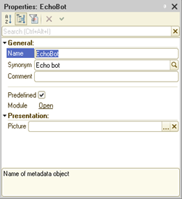
Fig. 517. Echo bot properties
Place the following text in the object module for the created bot:
Procedure CollaborationSystemMessageProcessing(Message, AdditionalParameters)
Response = CollaborationSystem.CreateMessage(Message.Conversation);
Response.Text = "echo" + Chars.LF + ">" + StrConcat(StrSplit(Message.Text, Chars.LF), Chars.LF + ">");
Response.Write();
EndProcedureWhen you start the client application, the bot and the corresponding collaboration system user will be automatically created in the collaboration system. This will happen as the predefined bot was created.
If you send a message to the Echo bot, it will respond with a text that begins with echo. The next lines (in quote mode) will display the text that was sent to the bot.
Echo bot and messenger
As mentioned earlier, a 1C:Enterprise bot can participate in conversations initiated from instant messaging systems (messengers). For an object of the CollaborationSystemBot type to process messages from a messenger, take the following actions:
-
Create a bot.
-
Integrate 1C:Enterprise and a messenger.
-
In the integration settings, specify the collaboration system user who represents the bot as the default conversation participant.
Other operations are similar to the operations with a messenger. The only feature is that one of the users or the only user who receives a message from the messenger will be a collaboration system user who represents a 1C:Enterprise bot.
If you add a collaboration system user of a previously created "Echo bot" to an existing integration with an instant messaging system, a response to each message of an external user will be generated as a given question. We do not recommend that you do it for an integration that deals with some real needs of external users.
29.4.6.3.4. Processing messages from the collaboration system
General information
In general, messages are received from the collaboration system and processed as follows:
-
Platform creates a network connection with the collaboration system when executing the ProcessBots() method of the collaboration system manager. This connection is held for 2 minutes. Every time the ProcessBots() method is called, the timeout starts from the moment the method is called. If there is no method call within 2 minutes, the network connection is closed and the interaction with the collaboration system is interrupted. This behavior does not depend on the infobase mode (file or client/server) used for the collaboration system operations. In this regard, we recommend that you call the ExecuteProcessing() method using a scheduled job that must run once a minute.
-
Several background jobs process messages received from the collaboration system. Their behavior depends on whether you use file or client/server infobase mode. For more information, read below in this chapter. To learn more about file mode, read below in this chapter.
-
Once the collaboration system notifies the platform of a new message, the following background jobs start:
-
Background job for receiving messages runs in response to a collaboration system notification. The background job receives a message, places it in the infobase message queue, notifies the collaboration system of the message, and terminates.
-
The next step is to start the background job for processing the message queue. This background job analyzes the message queue and starts background jobs to process received messages. When started, the background jobs are passed the ID of the message being processed. It is also specified on whose behalf and in which data area the background job must run. Having processed the whole queue, the background job closes.
-
Finally, run the background job to process the received message. This background job processes a particular message. It runs on behalf of a particular user and in a particular data area. This background job calls the bot object module handler. This handler processes the collaboration system message.
-
These background jobs:
-
Provide similar operation procedures in file and client/server modes.
-
Optimize latency when receiving messages from the collaboration system.
-
Ensure the background job for processing a particular message is executed in a particular data area and on behalf of a particular user with minimal overheads.
-
Lower overheads on receiving messages from the collaboration system.
File mode
Each background job for processing messages always processes one message and terminates. If there is no message to process, no messages are waited for. Note that in file mode, background jobs always run sequentially. It is provided by one client application instance. A new message is processed as follows:
-
When the platform receives a new message via an established network connection, it starts the background job for receiving messages. This background job runs with the highest priority. In other words, no matter how many background jobs are waiting to be executed when a message is received from the collaboration system, the background job for receiving messages is always started after the current background job (if any) is completed.
-
The background job for receiving messages receives one message. The message is written to the database message queue. The background job for processing received messages is started. In fact, it is scheduled to be started. The background job for receiving messages is completed.
-
Background job for processing the message queue receives one message from the queue. The following parameters for processing this message are determined: the username and password on whose behalf the message will be processed, and the parameters of the data area within which the message will be processed. Background job for processing received messages is then scheduled to run. The received message is passed to this background job. The background job is started with the predefined parameters. The background job for processing the message queue then analyzes whether there are unprocessed messages in the local queue or not. If there are some messages, the background job for processing the message queue schedules its restart. After all the above actions are completed, the background job for processing the queue is completed.
-
The background job for processing received messages calls the bot message handler. If a message is received successfully, it is marked as processed in the queue. If the code in 1C:Enterprise language terminates abnormally, there will be one more attempt to process the message. Once these actions are completed, the background job is completed.
Client/server mode
In client/server mode, all three background jobs for managing messages are always started. However, the background job for processing received messages does not terminate after the processing but "falls asleep" for 20 seconds. If you need to process a new message from the collaboration system within these 20 seconds, it will be processed pretty fast as the server cluster does not spend time on creating a new background job session. If a new message is received more than 20 seconds after the previous message, the background job is restarted. A new message is processed as follows:
-
When the platform receives a new message via an established network connection, it passes control to the background job for receiving messages. This background job receives all the messages from the collaboration system, writes them to the database message queue, and notifies the background job for processing received messages.
-
The background job for processing the message queue takes control after it receives a new message. For each of the received messages, the parameters for starting the background job for processing received messages are determined. Then the ID of the message to be imported is passed to the background job for processing received messages.
-
Background job for processing received messages calls the handler for receiving a collaboration system message. This handler is located in the bot object module. If a message is received successfully, it is marked as processed in the queue. If the code in 1C:Enterprise language terminates abnormally, there will be one more attempt to process the message. Once these actions are completed, the background job is completed, considering the features described at the beginning of this section.
Thus, the key difference between file mode and client/server mode is basically the way the background jobs work. In file mode, only one background job runs at a time and background jobs are executed sequentially. In client/server mode, they can run simultaneously.
29.4.7. Shared use
In the collaboration system, you can combine several applications registered in the collaboration system into a single space. In the applications are combined, users of all combined applications become the users of the collaboration system. When combining applications, the exchange of the messages between applications becomes possible. Only the owner of the subscriber of all combined applications can combine applications. The shared use is supported:
-
By the 1cDialog.com service.
-
By the 1C:Collaboration server product.
To combine applications, you can use the standard function of the 1C:Enterprise system (when using the 1cDialog.com service) or implement the necessary code in 1C:Enterprise language (when using the 1C:Collaboration server instance).
The geographically distributed organization, i.e. a chain of stores and the central office of the chain, is an example of situation when such application combining is necessary. Each store and central office has its own infobase. At the central office you can deploy an instance of the 1C:Collaboration server or use the 1cDialog.com service. Databases are registered in the selected service (each store and the central office). Then the resulting applications are combined. The result is a single information space where users of all databases can communicate in real time.
To combine applications, you should use the CollaborationSystemApplicationLinks object. The list of applications to be combined can be set using the Applications property of this object. This property can be filled using the GetSubscriberApplications() function call. This method should be called when operating on behalf of the user who owns the subscriber.
In addition to the list of combined applications, the CollaborationSystemApplicationLinks object allows you to specify how to match the collaboration system users of combined applications:
-
By name (the Name value). Collaboration system users with the same Name property are considered the same users.
-
By full name (the FullName value). Collaboration system users with the same FullName property are considered the same users.
-
By mapping key (the MatchingKey value). Collaboration system users with the same MatchingKey property are considered the same users. In this way you can perform a selective matching of the application users. The users matched between different applications should be specified using the MatchingKey property. In this case, users with the same keys are transparent for the combined applications, and other users are available only within the scope of "their" collaboration system applications.
The user matching method is selected using the UserMatching property.
Finally, the ConversationContextMatching property of the CollaborationSystemApplicationLinks object allows you to specify that objects having the same identifier in different applications are considered the same within the combined application information space. So, if the conversation contexts are mapped within the distributed information system, one document can be accessed from different applications (infobases).
After combining several applications, they begin to function according to the "all with all" scheme. It means that each of the combined applications can interact with any other combined application. At the same time, the collaboration system does not support the following scheme: Application1 is merged with Application2, and Application2 is merged with Application3, but Application3 cannot interact with Application1.
To cancel an application combination, use the CancelSubscriberApplicationLinks() method. Cancel shared use in the same way you set a map: create a list of applications you no longer want to use together (at least two), and call the CancelSubscriberApplicationLinks() method.
Using the CollaborationApplicationSharing() method, you can get a list of shared applications and sharing options. You should take into account that shared applications are returned in pairs.
29.5. Integration with various systems
29.5.1. General information
The collaboration system supports integration with various systems external to the collaboration server and 1C:Enterprise. These include: instant messaging systems, systems that can only call an HTTP service, and websites where you can install the client of a collaboration system conversation.
An instant messaging system is client/server software designed to exchange different messages between users of these systems. The client application is installed on the user's computer or other device. This application is most often referred to as a messenger or by the system name. In this chapter, the term "messenger" is used. A web application can also be a client application. As a rule, all interaction is done via a centralized server or servers of the instant messaging system. Client applications connect to "their" server. Currently, the most popular systems are VKontakte, Telegram, WhatsApp, Viber, and other.
In the collaboration system, you can establish interaction between a 1C:Enterprise application and one of the supported messengers. This interaction can be characterized as interactive and two-way. This means that the interaction basically involves a dialogue between people, and both sides actively participate in this interaction. Active participation means the ability to create messages in a conversation.
In addition to such interaction, there are other interaction schemes. For example, there is an executive system where some events take place. The application must receive information that an event has occurred and then perform some actions. You can implement such interaction scheme in different ways:
-
Call the API methods of the executive system.
-
Implement Internet services in the application that will be called by the executive system.
-
Offer the executive system to use webhooks. This feature is a URL on the collaboration system server where you need to send a POST request with a specially formatted request body. Having received the request, the collaboration system server starts calling the associated 1C:Enterprise features. Use this method to implement machine and one-way interaction between the executive system and the application. 1C:Enterprise can receive messages only from an external source.
If 1C:Enterprise serves an online store, you might need to implement a chat on your website. Users can write to this chat and get answers from a company employee. It is desirable that 1C:Enterprise users do not have to use another system to respond to website users. This interaction is similar to integration with a messenger but with a different client application.
To learn more about different integration process options, read below in this chapter.
29.5.2. External systems
29.5.2.1. Operating with external systems
To integrate an external system with the application:
-
In an external system, perform the actions necessary for interaction with a third-party software. For example, create a bot or community, customize the software, and so on.
-
In the application, create a new integration between the collaboration system and the external system. You can do it using the standard function or programmatically.
Further, the external system object that represents an integration (a bot, a community, and so on) of the external system and the collaboration system will be called the integration user. In other words, a person will text the interaction user to write a message that will first get to the collaboration system and then to the application.
In the integrated system, the interaction will look as follows:
-
External system user finds the integration user associated with the application. You can search for the user in any way supported by the external system (by name, by QR code, and so on).
-
Then the user writes a message to the found integration user.
-
External system passes the message to the collaboration system.
-
Upon receiving an incoming message, the collaboration system server:
-
Creates a new collaboration system user for each new external system user. The user is marked as external. Information about the user is filled based on the data received from the external system.
-
Creates an out-of-context group displayed conversation (if there is no created one) for this user. This conversation gets a special mark that this is a conversation with the "external" world. The conversation title has the name of an external user or a messenger group chat. The conversation title shows the external system where the conversation was started. The title type depends on whether the external system integration user is texted directly or added to a group. It depends on the used external system.
-
For the created conversation, a user list is created. This list includes: the user who started the conversation and all users specified when the integration was created. The external user is displayed with the corresponding mark.
-
Received message is added to the created conversation. The external user becomes the message author. In the collaboration system, notifications are generated according to the standard rules. Notifications are not created for external users.
-
-
Message sent from the collaboration system to the external system will be written on behalf of the integration user as they are named in the external system. The external user of the collaboration system (the one who started the conversation) will be a recipient.
So messages from external users will be personalized in the collaboration system up to the way the user is named in the external system. Messages sent from the application to the external system will be anonymous. So the message author will be the integration user, not the actual message author. That is why it will be impossible to identify the actual application user who wrote a message in the external system.
If you use external systems, keep in mind that:
-
Each external system can have a list of restrictions.
-
In general, integration with external systems supports file operations, but each external system has its own specifics. For more information, see the collaboration server documentation.
29.5.2.2. Technical features of integration
29.5.2.2.1. Receiving a list of available external systems
A list of external systems that can be integrated with 1C:Enterprise depends on the collaboration server. You can change the list of external systems supported by the collaboration server within one full version of 1C:Enterprise. Do not rely on the fact that the list of supported external systems does not change and depends on the 1C:Enterprise version.
To get a list of available external systems, use the GetExternalSystemTypes() function of the collaboration system manager. Each external system will have its text name. The external system type received from the list will be further used in different methods upon integration creation.
29.5.2.2.2. Information about external systems
Once you have chosen an external system for integration, get information about this external system. Use the GetExternalSystemDescription() function of the collaboration system manager. The result of the call will be an object of the CollaborationSystemExternalSystemDescription type. The object contains the external system name (the Type property) and the list of parameters required to connect to the external system (the ParametersDescription property).
Each parameter is represented by the CollaborationSystemExternalSystemParameterDescription object. Each parameter has a name (the Name property) and a flag specifying that this parameter is required (the IsRequired property). The type of any external system parameter will be String. The set of parameters depends on the corresponding integration module of the collaboration system.
29.5.2.2.3. Integration parameters
General information
In this section, you can find a brief description of the parameters of various types of collaboration system integrations.
Telegram
| Parameter | Description |
|---|---|
| Token | Token required to use the Telegram API. Returned by the BotFather bot when you register the bot for integration. The token must be unique among all infobases registered in the used collaboration server. In other words, one Telegram bot cannot be connected to different infobases of the same collaboration server. |
VKontakte
| Parameter | Description |
|---|---|
| groupID | VKontakte group ID generated when you create a VKontakte group. |
| Token | Access key required for the collaboration system to use the VKontakte API. |
| Parameter | Description |
|---|---|
| Channel | Chat title in WhatsApp. |
| Token | Access token received from the service owner. It is required for the collaboration system to use the WhatsApp API. |
Website chat
| Parameter | Description |
|---|---|
| allowVideoconferences | Possible values: allowed, allowedToWebChatOnly, and disallowed. Default value: allowed. The allowed value allows you to make video calls to and from the chat. The allowedToWebChatOnly value allows you to make video calls to the chat but prohibits making video calls from the chat. The disallowed value prohibits making video calls to and from the chat. If video calls are unavailable on the collaboration system server or the chat is connected over HTTP protocol, the parameter value is considered disallowed, regardless of what value is set. |
| colorTheme | Possible values: auto, light, and dark. Default value: auto. The color scheme of the chat window. By default, the theme is the same as in the web browser. |
| defaultApplicationUserCameraState | Possible values: on and off. Default value: on. The parameter turns on or off the camera of the client device when a video call starts. |
| displayUserPictures | Possible values: true and false. Default value: true. Allows displaying user images in the chat. |
| languageCode | Required parameter. Chat localization language including internal messages. It is set by a 2- or 4-letter ISO code. You can view the detailed list in the standard data processor of collaboration system management. |
| mobileButtonOrientation | Possible values: leftBottom and rightBottom. Default value: rightBottom. Specifies the position of the chat button in the mobile version: bottom left or top left. |
| orientation | Possible values: left, bottom, and right. Default value: bottom. Specifies the chat orientation. |
| orientationPadding | Possible values: 0, 50, 100. Default value: 100. Specifies the vertical position of the chat. |
| signKey | Signature key used to match the chat user and the collaboration system. For how to use the parameter, see Chat interface. |
| titleBackColor | Default value: #FBEDE9. Allows you to specify the background color of the chat title. |
| titleText | Default value: empty string. Sets the text to display in the chat title. |
| titleTextColor | Default value: #333333. Allows you to specify the color of the chat title characters. |
The underlined parameter in the table is a required parameter.
29.5.2.2.4. Creating an integration and its properties
If you know the external system type and parameters, you can create an integration. To do this, use the CollaborationSystem.CreateIntegration() method. Then, fill in all parameters of the integration you are creating and save this object. The integration is described by an object of the CollaborationSystemIntegration type. When you create integration, specify the following properties:
-
ExternalSystemType. String that contains the name of the external system (messenger) with which the integration is being created. The property value must be the same as one of the values received after calling the GetExternalSystemTypes() function.
-
Key. Value that allows you to identify the integration being created within the infobase.
-
Use. Indicates that the integration being created will be used by the collaboration system.
-
ExternalSystemParameters. Contains a map where each KeyAndValue pair has information about one external system parameter. Specify the required parameters in any case. Whether to fill other parameters depends on the external system used.
-
Presentation. String that describes the integration to be created and is a human-readable text. This text is not an integration user presentation in the messenger.
-
Participants. List of the collaboration system users who will receive notifications of new messages in the conversation being created. Conversation participants can be both real system users (specific individuals) and bots implemented in the application. The bot can be the only participant in the conversation by default. The bot can connect other users after analyzing the initial message of the external system user. To find out how to create bots in 1C:Enterprise, see Collaboration system bots. To find out how to connect bots to integrate with an external system, see Echo bot and messenger.
-
ID. Value of the CollaborationSystemID type that is created when a new integration is written to the infobase. The ID is created by the collaboration system server.
The integration is created the first time you save the CollaborationSystemIntegration object using the Write() method. Once the integration is written, some properties of this object are filled with values that show the capabilities of the created integration.
The MessageEditingAvailable property specifies whether you can edit messages placed in conversations related to this integration. The property value depends on the integration type and cannot be changed by the developer. If this property is set to False, you cannot change an already existing message. If you call the Write() method, an exception is thrown.
The VideoconferencesAvailable property specifies whether the users of this integration can make video calls. The property value depends on the integration type and cannot be changed by the developer. If this property is set to True, the integration user can make video calls. For chats on websites (the WebChat external system type), this property is set to True only if the allowVideoconferences integration parameter is set to true.
The EndpointURL property contains a URL to be provided to the external system if necessary:
-
If you use a webhook, the value of this property is the address to which the external system will send a POST request.
-
If you use a chat, specify the value of this property in the text of the website client. This allows the website to load the chat.
29.5.2.3. WhatsApp message templates
You can interact with WhatsApp only if you have a business account. To create business accounts, contact the authorized service owners. 1C:Enterprise-based systems support the Devino Telecom service owner (https://www.devinotele.com/ru/).
Integration within a business account imposes some restrictions:
-
You can give an arbitrary response to a user's question within 24 hours from the last user message in the chat. We will call this interval the "arbitrary response period".
-
Once this window is closed, you can only send template messages.
-
To create template messages, use the web interface provided by the service owner Template messages must be approved in WhatsApp.
-
You cannot edit messages sent to a messenger chat.
-
Knowing the user phone number, 1C:Enterprise can be the first to start interaction. Only a template phrase can be used as a message. An example of such action will be given further in this section.
Besides these specifics, 1C:Enterprise imposes its own restrictions on interactions:
- Commands in messages are not supported.
Although message templates are created on the service owner's side, 1C:Enterprise provides an API that simplifies the operations with these templates.
Firstly, the collaboration system manager allows you to get the end time of the arbitrary response period. To do this, use the GetAnswerAvailabilityEndTime()/GetAnswerAvailabilityEndTimeAsync() method. This method returns the end time of the arbitrary response period in the time zone of the current computer. If the method is used for other integration types, the return value is Undefined.
Secondly, the system allows you to get templates that will be used to generate responses. To do this, use the GetMessageTemplates()/GetMessageTemplatesAsync() method of the collaboration system manager. The first time this method is called, the collaboration system server accesses the service owner, receives approved templates, and stores them in its database. Then these templates are passed to 1C:Enterprise. The collaboration system server regularly updates the list of approved templates. So templates are not stored in 1C:Enterprise (it is not required).
Message templates are returned as an array of objects of the CollaborationSystemMessageTemplate type. Let's take a closer look at this object. This object has a certain set of properties. All properties are read-only:
| Property | Description |
|---|---|
| ID | Value of the CollaborationSystemMessageTemplateID type. This value allows you to distinguish one message template from another. |
| Name | Template name as set by the service owner. |
| LanguageCode | Code of the language in which the template is set. The language code is set on the service owner's side. You can have templates of the same message in different languages. The code is set as a string. |
| Text | String that is a message template. Within this template, you can use parameters called placeholders. In the template body, they are presented as double braces with a placeholder number. The numbers must start with 1 and must not have gaps in the numbering. The string can look as follows: Good afternoon, {{1}}! You have placed order {{2}}. To track it, you can follow the link: {{3}}. This template contains three parameters with numbers from 1 to 3. |
| Presentation | String that can contain a template presentation understandable to the 1C:Enterprise user. |
| PlaceholdersPresentations | Fixed array where each array element contains a text description of each parameter. You can use these presentations for the message dialog box. For the template from the Text property description, placeholder presentations may be as follows: · Username. For parameter number 1. · Order number. For parameter number 2. · Order card URL. For parameter number 3. The parameter number is mapped to the array element by index calculated as "parameter number 1". |
You can remember the specific template ID and, if necessary, get this template using the GetMessageTemplate()/GetMessageTemplateAsync() method and specifying the required template ID.
When you generate a template collaboration system message to be sent to the WhatsApp integration:
-
Get the desired message template.
-
Create a collaboration system message for the required integration.
-
Specify the MessageTemplate property in the message. To do this, use the message template ID. If this property is specified, the following message properties are ignored when writing a message: Text, Attachments, Data, and Actions.
-
Specify the MessageTemplatePlaceholdersValues message property. This property contains an array of values that will replace the parameters in the template. The replacement is handled directly by the WhatsApp server. For a saved message, this property contains the parameters specified when the message was created.
When the Write() message method is called, a message is sent to the WhatsApp system servers. On these servers, values are substituted, and the message is published in the messenger chat.
To specify presentations of a template and placeholders, use the SetMessageTemplatePresentation()/SetMessageTemplatePresentationAsync() collaboration system method. In the method, specify the template ID and the presentation of the template (the formal TemplatePresentation parameter) and the placeholders (the formal PlaceholdersPresentations parameter). Placeholder presentations are specified as an array. The presentations are stored by the collaboration system servers. The next time the message template is received, all previously specified presentations will be saved.
If interactive user actions are required to generate a template message, you can use the 1C:Enterprise dialog box for that or create another dialog box using configuration tools.
To generate the dialog box, first create the CollaborationSystemMessageTemplateChoiceProcessing event handler of the application module. The handler of this event gets control when the user click s Send template message. In the formal Conversation parameter, the handler receives the ID of the collaboration system conversation where the template message will be created. The StandardProcessing parameter is responsible for displaying a standard dialog box for sending a template message. To preview the message text with replaced placeholders in the dialog box to be created, use the GetTextWithPlaceholders() method of the CollaborationSystemMessageTemplate object.
To start the conversation first, knowing the user phone number, you can use the following code:
// Create a conversation with an external ID,
// so privileged mode is required
SetPrivilegedMode(True);
Conversation = CollaborationSystem.CreateConversation();
Conversation.Integration = IntegrationID;
Conversation.ExternalID = UserPhone;
Conversation.Write();
Message = CollaborationSystem.CreateMessage(Conversation.ID);
Message.MessageTemplate = MessageTemplateID;
Message.MessageTemplatePlaceholdersValues.Add(PlaceholderValue);
Message.Write();The following variables are used in this example:
-
IntegrationID. Value of the CollaborationSystemIntegrationID type. The value can be obtained from the ID property of the CollaborationSystemIntegration object that describes WhatsApp integration.
-
UserPhone. A String type value. The value contains the user number in international format, without the leading "+" character, for example, 78881234567.
-
MessageTemplateID. CollaborationSystemMessageTemplateID type. ID of the message template that will be displayed to the WhatsApp user.
-
PlaceholderValue. Arbitrary type. The value that is used to generate the resulting message.
29.5.3. Actions in external systems to create integrations
29.5.3.1. General information
In this section, you can find out what you need to do in an external system so that the collaboration system can interact with this external system.
29.5.3.2. Telegram
Note. Note. This is the current description of external system operations.
To integrate the collaboration system with Telegram, create a bot in the messenger that will represent the collaboration system. To do this, follow these steps:
-
Find the BotFather bot in Telegram or follow the link https://telegram.me/botfather).
-
Read the greeting text and then click Start to start communicating with the bot in the chat (in Telegram).
-
Enter the /newbot command to create a new bot or choose the appropriate hyperlink in the command list.
-
Enter the bot name in response to the bot request. The entered text will be a presentation of the bot being created in Telegram.
-
Enter the bot ID in response to the bot request. This name must:
-
End with the bot suffix.
-
Be unique in Telegram.
- Telegram will create a bot and send a token. This is required for an application external to Telegram to use the HTTP API of Telegram. Save this value. You will need it to create integration in the collaboration system. It is recommended that you treat this key as confidential information.
After you create the bot in Telegram, create an integration in the infobase. To do this, open the standard Collaboration system management data processor, and take the following steps:
-
Click Integrations.
-
Add a new integration.
-
Specify the Telegram bot presentation in the collaboration system (the Name field).
-
In the External system type field, select Telegram.
-
Allow integration (select the Use checkbox).
-
In the parameters, specify the token that was sent by the BotFather bot when you created your bot as a value of the token parameter.
-
After that, specify the users that will be the default participants of the group conversation in the collaboration system (the Default conversation members table). If you do not specify the users, no one can see messages from Telegram.
-
Click OK to create integration and connect the collaboration system to Telegram.
29.5.3.3. VKontakte
Note. Note. The description of operating with the web interface is given as of the time of writing the documentation.
To integrate the collaboration system with VKontakte, the user performing actions in the VKontakte web interface must have the community administrator rights. To create an integration, get a VKontakte group ID and a token. To do this, take the following steps in the VKontakte web interface:
-
On the VKontakte website (https://vk.com), go to the page of managing the selected community, or create a new community.
-
Go to Manage – Settings – API usage – Access tokens.
-
On this page, click Create token. When you create a token, select the following rights:
-
Allow access to community management.
-
Allow access to community messages.
-
Allow access to documents.
-
Click Create to create an access token. Save the created access token. You will need it to create an integration in the collaboration system. It is recommended that you treat this key as confidential information.
-
Go to Manage – Settings – API usage – Callback API. On this page, get the ID of the created group. For this, find text of the {"type": "confirmation", "group_id": 123456789} type on the page. In this text, 123456789 is the group ID that you need to remember.
-
Go to Manage – Settings – Messages. On this page, enable Community messages and click Save.
Once you have taken the required actions, create an integration in the infobase. To do this, open the standard Collaboration system management data processor, and take the following steps:
-
Click Integrations.
-
Add a new integration.
-
Specify the VKontakte community presentation in the collaboration system (the Name field).
-
In the External system type field, select VK.
-
Allow integration (select the Use checkbox).
-
In the Parameters table, specify the integration parameters:
-
In groupID, specify the VKontakte group ID.
-
In token, specify the VKontakte group access token.
-
After that, specify the users that will be the default participants of the group conversation in the collaboration system (the Default conversation members table). If you do not specify the users, no one can see messages from the VKontakte group.
-
Click OK to create integration and connect the collaboration system to VKontakte.
29.5.3.4. WhatsApp
Note. Note. The description of operating with the web interface is given as of the time of writing the documentation.
To integrate the collaboration system with WhatsApp, conclude a contract with the WhatsApp Business API provider, Devino Telecom company. For more information on how to conclude a contract and receive necessary data, go to https://v8.1c.ru/static/instruktsiya-po-podklyucheniyu-k-whatsapp-business-api/.
Once you have taken the required actions in your Devino Telecom account, create an integration in the infobase. To do this, open the standard Collaboration system management data processor, and take the following steps:
-
Click Integrations.
-
Add a new integration.
-
Specify the WhatsApp channel presentation in the Name field of the collaboration system.
-
In the External system type field, select WHATSAPP_DEVINO.
-
Allow integration (select the Use checkbox).
-
In the Parameters table, specify the integration parameters:
-
In the channel parameter, specify the name of the channel to be used for communication.
-
In the token parameter, specify the token (access key) received from Devino Telecom.
-
After that, specify the users that will be the default participants of the group conversation in the collaboration system (the Default conversation members table). If you do not specify the users, no one can see messages from WhatsApp.
-
Click OK to create an integration and connect the collaboration system to WhatsApp.
-
After configuring the integration, transfer the value of theConnection point URL field (the field is located below the integration list) to your Devino Telecom manager.
29.5.4. Webhooks
29.5.4.1. Using webhooks
As mentioned earlier, if you use webhooks, integration is one-way. Messages are sent from the external system to the collaboration system, and then to the application.
The user who will represent the system that sends messages to the application will be called an integration user. So that the external system can use a webhook, it must be provided with the endpoint URL. To get it, use the CollaborationSystemIntegration.EndpointURL() method. Use this address when you set up the system that will send messages.
Once a message from the external system gets to the endpoint, perform the following actions:
-
Parse the message body.
-
Create an integration user if there is no created one.
The integration user name is:
-
Username passed in the createUser message.
-
Integration instance name if no user (message author) is specified in the external system message.
-
Create a collaboration system conversation if there is no created one.
-
Conversation participants are:
-
Integration user.
-
Users that were specified as default participants upon integration setup.
-
-
If you want messages to get into a pre-created conversation with the selected participants, you need to:
-
Pre-create a conversation using 1C:Enterprise language.
-
Pass the created conversation ID to an external system so that this system uses this ID in its messages. To get a string presentation of the conversation ID, use the String() function whose parameter is an object of the CollaborationSystemConversation.ID type.
-
-
-
Message whose author is an integration user is added to the conversation. This message depends on the external system message.
29.5.4.2. Supported commands
29.5.4.2.1. General information
The command is a POST request of an external system. The request must meet the following requirements:
-
Request body is generated in UFT-8 without BOM.
-
Request body is a JSON document.
-
Request body generally looks as follows:
{
"command" : {
"param1": value1, ... "paramN": valueN
}
}If the command allows HTML text, the following formatting options are supported:
-
Supported elements: a, b, big, font, i, li, ol, s, small, span, strike, strong, u, and ul.
-
style element attribute: background-color, color, font-family, font-size, font-style, font-weight, or text-decoration.
The command result is displayed as a return code:
-
200 OK. Command is completed successfully.
-
404 No active integration. Integration is not found or not active.
-
409 Conflict. When you call the create… command for an already existing object.
-
500 <Error text>. Error occurred when processing the command.
For more information about the command formats, see below.
29.5.4.2.2. createConversation
Description:
Creates a new conversation.Syntax:
{
"createConversation":
{
"extConversationId":
"1", "title":
"Conversation title", "extUserId":
"1", "members": [
"1"
]
}
}
Parameters:
- extConversationId. External ID of the conversation to be created.-
title. Title of the conversation to be created (as a string).
-
extUserId. External ID of the user on whose behalf the conversation is created.
If not specified, a collaboration system user with the same name as the integration name will be created and added to the conversation. In this case, all requests related to this conversation must not include the extUserId, members, addMembers, and removeMembers parameters.
Optional parameter.
- members. Array of external IDs of users who are conversation participants from the external system.
Optional parameter.
29.5.4.2.3. createMessage
Description:
Creates a new message in the conversation.Syntax:
{
"createMessage": {
"extId":
"1", "text":
"Message text", "textFormat":
"text/plain", "extUserId":
"1", "extConversationId":
"1", "data":
"", "dataType":
""
}
}
Parameters:
- data. Arbitrary data attached to the message.Optional parameter.
- dataType. MIME type that describes the data specified in the data parameter.
Optional parameter.
-
extConversationId. External ID of the conversation where the message is being created.
-
extId. External ID of the message to be created.
-
extUserId. External ID of the message author.
If not specified, a collaboration system user with the same name as the integration name will be created and added to the conversation. In this case, all requests related to this conversation must not include the extUserId, members, addMembers, and removeMembers parameters.
Optional parameter.
-
text. Message text.
-
textFormat. Message text format. Possible values: text/plain, text/html. The default value is text/plain.
Optional parameter.
When creating a message using this method, the developer can program the transfer of the following files:
-
Pictures. The actual picture is passed by the data property value in the Base64 format. In the dataType property, specify the correct MIME type for the picture to pass.
-
Any binary data. The data is passed by the data property value in the Base64 format. Set the dataType property to application/octet-stream.
-
The 1C:Enterprise value that supports XDTO serialization. The data is passed by the data property value in JSON format. Set the dataType property to application/json+xdto.
-
Any string. The data is located in the data property. In the dataType property, specify the correct MIME type value.
When generating the CollaborationSystemMessage object based on the createMessage command, the Data and StringDataFormat properties are filled in as follows:
-
If the dataType parameter contains the image/* MIME type:
-
The Data property contains a value of the Picture type generated based on the value of the data parameter.
-
The StringDataFormat property contains Undefined.
-
-
If the dataType parameter contains the application/octet-stream MIME type:
-
The Data property contains a value of the BinaryData type generated based on the value of the data field.
-
The StringDataFormat property contains Undefined.
-
-
If the message data format is application/json+xdto:
-
The Data property contains a value which is the result of the XDTO deserialization of a string from the data parameter.
-
The StringDataFormat property contains Undefined.
-
-
In all other cases:
-
The Data property contains the data parameter value.
-
The StringDataFormat property contains the dataType parameter value.
-
29.5.4.2.4. createUser
Description:
Creates an integration user in the collaboration system.Syntax:
{
"createUser" : {
"extUserId": , "name": , "fullName": , "picture":
}
}
Parameters:
- extUserId. External ID of an external user.-
name. Short name of an external user (as a string).
-
fullName. Full name of an external user (as a string). It can be an empty string.
-
picture. User picture as a string in Base64 format. Optional parameter.
29.5.4.2.5. updateConversation
Description:
Changes the conversation parameters. Use it to change the conversation title, and add or delete conversation users.Syntax:
{
"updateConversation":
{
"extConversationId":
"1", "title":
"New conversation title", "extUserId":
"5", "addMembers": [
"5"
], "removeMembers":
[
"1"
]
}
}
Parameters:
- extConversationId. External ID of the conversation being changed.- title. Conversation title.
Optional parameter.
- extUserId. External ID of the user on whose behalf the conversation is being changed.
If not specified, a collaboration system user with the same name as the integration name will be created and added to the conversation. In this case, all requests related to this conversation must not include the extUserId, members, addMembers, and removeMembers parameters.
Optional user.
- addMembers. Array of external IDs of users to be added to the conversation participants.
Optional parameter.
- removeMembers. Array of external IDs of users to be removed from the conversation participants.
Optional parameter.
29.5.4.2.6. updateMessage
Description:
Updates an existing message.Syntax:
{
"updateMessage": {
"extId":
"1", "text":
"Message text", "textFormat":
"text/plain", "extUserId":
"1", "extConversationId":
"1"
}
}
Parameters:
- extId. External ID of the message being changed.-
text. Message text.
-
textFormat. Message text format. Possible values: text/plain, text/html.
Optional parameter. The default value is text/plain.
- extUserId. External ID of the message author.
If not specified, a collaboration system user with the same name as the integration name will be created and added to the conversation. In this case, all requests related to this conversation must not include the extUserId, members, addMembers, and removeMembers parameters.
Optional parameter.
- extConversationId. External ID of the conversation where the message is being changed.
29.5.4.2.7. updateUser
Description:
Updates the parameters of an integration user in the collaboration system.Syntax:
{
"updateUser" : {
"extUserId": , "name": , "fullName": , "picture":
}
}
Parameters:
- extUserId. External ID of an external user.-
name. New short name of an external user (as a string). Optional parameter.
-
fullName. New full name of an external user (as a string). Optional parameter.
-
picture. New user picture as a string in Base64 format. Optional parameter.
29.5.5. Website chat
29.5.5.1. General information
This integration method allows a user of a certain website to communicate with a company that uses this website for its activities. This can be an online store, a showcase with product examples, and other.
To implement such integration:
-
Customize both client and server of the website so that the user can start a chat conversation on this website. If necessary, the website code can use the chat API for some actions.
-
Create the required integration type in 1C:Enterprise.
-
Implement the required interaction with the chat in 1C:Enterprise language if necessary. If the chat is used only in messenger mode (only for interactive text messaging), no additional actions are required.
29.5.5.2. Chat interface
To connect the chat to the website, insert the following code snippet into the website code:
<script src="<URL точки
подключения>" async></script>You can get the endpoint URL either when creating an integration (in the standard data processor for binary data storage management) or using the EndpointURL() method of the CollaborationSystemIntegration type.
After importing the chat interface, the CollaborationSystemWebChat1CE object of the CollaborationSystemWebChat1CEClass type becomes available in the global context of the website. You can use this object to interact with the chat.
The CollaborationSystemWebChat1CE object provides the following methods:
open()
Description:
Expands the chat window.Return value:
void.
close()
Description:
Collapses the chat window.Return value:
void.
setContactInfo(<contactInfo>)
Description:
Sets the user's contact information.Parameters:
contactInfo required
Object.
An object that contains values of the user contact data fields. The object has the following properties:
-
name – String type – contains the username.
-
fullName – String type – contains the full username.
-
email – String type – contains the user's email address.
-
phone – String type – contains the user's phone number.
Return value:
void.
getContactInfo()
Description:
Returns the contact information submitted by the user in the presentation form.Return value:
Promise<Object>. The promise execution result is an Object type value. It contains the following properties:
-
name – String type – contains the username.
-
fullName – String type – contains the full username.
-
email – String type – contains the user's email address.
-
phone – String type – contains the user's phone number.
setMatchingKeyToken(<matchingKeyToken>)
Description:
Sets a token with the key for matching a collaboration system user and a website user.Parameters:
matchingKeyToken required
String.
A token with the key for matching a collaboration system user and a website user. The token can be signed (JWS) using the signKey signature key created in the integration parameters, or not signed (JWT). This mapping key will be available through the ExternalSystemUserID property of the CollaborationSystemUser type.
Return value:
void.
logout()
Description:
Terminates the session for the current user in the chat.Return value:
Promise<void>. The promise execution result is a void type value.
isVideoconferenceEnabled()
Description:
Returns information on the availability of video calls.Return value:
Promise<Boolean>. The promise execution result is a Boolean type value:
-
true. Video calls are available.
-
false. Video calls are unavailable.
startVideoconference()
Description:
Starts a video call from a website user to a 1C:Enterprise system user.Return value:
Promise<Boolean>. The promise execution result is a Boolean type value:
-
true. Video call has started.
-
false. Video call was canceled.
sendMessage(<message>)
Description:
Sends the message text.Parameters:
Message required
Object.
A message to send to the chat. The object has the following properties:
-
text – String type - a message text.
-
textFormat - String type – a message type: text/plain or text/html.
Return value:
void.
addListener(<eventType>, <eventListener>)
Description:
Adds the <event> event handler.Parameters:
eventType required
String. The name of the chat event (described below).
eventListener required
Function. Contains a link to the event handler method.
Return value:
void.
removeListener(<eventType>, <eventListener>)
Description:
Removes the <event> event handler.Parameters:
eventType required
String. The name of the chat event (described below).
eventListener required
Function. Contains a link to the event handler method.
Return value:
void.
The CollaborationSystemWebChat1CE object allows you to handle the following chat events:
| Event | Description |
|---|---|
| close | Called when a chat is closed (collapsed). |
| initialized | Called after a chat is fully initialized and ready for use. |
| open | Called when a chat is open (expanded). |
| videoconferenceend | Called when a video call ends. |
| videoconferencestart | Called when a video call starts. |
Let's focus on mapping website users and collaboration system users. As noted earlier, the collaboration system always runs on behalf of a user. So any user who connects to the collaboration system must have their digital personification in the collaboration system. However, the user of the website where the chat is deployed and the collaboration system user usually do not know anything about each other.
Upon integration, you can:
-
Do not perform explicit mapping. In this case, the website user is "recognized" by the chat through the web browser data storage for some time. When they sign in from another computer or after a long period of time, a new collaboration system user is created. You do not need to do anything in this case.
-
Map users. In this case, you need to customize not only the client but also the server of the website. Briefly, the mapping scheme is as follows: the website software passes the UUID of the user currently logged into the website to the collaboration server. The collaboration server uses this ID to find its "own" user and sends conversation messages with this user to the website. Let's take a closer look at this scheme.
The website where the chat is deployed must pass the collaboration system some information to identify which website user is entering the chat. To do this, the website must generate a token in JWT or JWS (JSON Web Signature) format.
JWS is actually a signed JWT token. First generate a token whose payload contains the following claims:
-
sub. This claim must contain the website user UUID as a string. The CollaborationSystemUser.ExternalSystemUserID property will later send this value to 1C:Enterprise.
-
iat. This claim contains the JWT creation time according to the server time of the website into which the chat is being integrated.
JWT must be generated on the website server. Now you need to pass this token to the collaboration system chat. The chat will then pass this information to the collaboration server. To do this, use the setMatchingKeyToken() chat method. The collaboration server extracts the payload from the token and maps the website user with the collaboration system user. Then the collaboration server sends the conversation for the specified user to the website. If the website user changes (for example, the current user signs out and another user signs in), the website must generate another token for a new user and reset the mapping key. After that, the chat is updated.
You can use the above scheme if the signKey parameter is not specified in the integration settings.
The considered method has an unpleasant feature related to the security of integration and user data. If we assume that the website client is unreliable, an attacker can specify an arbitrary website user ID in the JWT claim and get access to someone else's data.
To avoid it, specify the signKey parameter in the integration settings. In this case, the collaboration server will expect a JWS token instead of a JWT token in the parameters of the setMatchingKeyToken() method. You also need to customize the website server so that after the necessary JWT is generated, the website server signs this token (generates JWS) using the key specified in the signKey integration parameter. Specify this key manually in the server code of the website. JWS must be generated using the libraries for operations with tokens of the programming language used to develop the website server.
As a result of these customizations, the client will not be able to change the JWT payload without violating the signature. The rest of the scheme remains the same: the setMatchingKeyToken() method transfers JWS to the chat, and the chat passes the token to the collaboration server. In this case, before you search for a user by information from the token payload, the collaboration server will verify the token signature. Further operations are allowed only if the passed token was not changed.
See also:
- JSON Web Signature: https://datatracker.ietf.org/doc/html/rfc7515.
29.6. Data dump and transfer
29.6.1. General information
You can use the functionality for saving and restoring data to transfer information between different collaboration servers. For example, you can transfer information from 1C:Dialog to your collaboration server and back. This functionality does not enable regular user data backup to save data in case of failures. To back up the database of the server and the external file storage, we recommend that you use standard tools of the PostgreSQL DBMS and the used storage.
For migration purposes, use the 1C:Enterprise API. With it, you can dump and restore data and use some service functions.
You can dump data either to a file in the file system or to a storage that you can access over Amazon S3 protocol (hereinafter referred to as the "storage").
By default, the collaboration system server allows you to store no more than 5 data dump files at the same time. The number of stored dump files is set up on the collaboration server and cannot be changed in 1C:Enterprise.
29.6.2. Data dump
To dump data, use the BeginCreateDataDump()/BeginCreateDataDumpAsync() methods. The parameter is a description of the data backup to create. After the method is executed, the system starts creating a dump file. The return value is a data dump ID (the CollaborationSystemDataDumpID type).
Data dump might take a long time. To reduce this time, you can get a dump description by its ID. To do it, use the GetDataDump()/GetDataDumpAsync() methods. These methods will generate the CollaborationSystemDataDump object. With the Status property of this object, you can monitor the current data dump state. The dump will be created when the CollaborationSystemDataDump.Status property becomes equal to CollaborationSystemDataDumpStatus.Done.
Besides the data dump execution status, the CollaborationSystemDataDump object gives you access to the following data:
-
ID. Data dump ID.
-
CreationDate. Date and time when the data dump is created or registered.
-
Description. Arbitrary data dump description.
-
Status. Data dump status.
-
RestorationStatus. Status of restoring data from the data dump. If the restore has not been performed or has not completed yet, the value is Undefined.
-
DownloadAvailable. Specifies that you can load a data dump file as a file.
After the data dump is created, you might need to get this backup as a file. To do it:
-
Check that you can get the data dump as a file using the CollaborationSystemDataDump.DownloadAvailable property.
-
Get a temporary link to the data dump file using the GetDataDumpAddress()/GetDataDumpAddressAsync() methods. If the data dump is created in the storage, the link has a limited lifetime, which is set up in the storage. If the data dump is created as a file, the method returns a path on the file system of the collaboration system server.
-
Save the file available by the link.
29.6.3. Data restore
The main data restore scenario is to restore data from a dump that is available "right here and right now". In other words, it is a data dump that is already located in the dump list and on the same collaboration system server. To restore data from such dump, get a backup ID and use the BeginRestoreFromDataDump() or BeginRestoreFromDataDumpAsync() method. For more information, see below.
Another restore data scenario is to use a data dump file stored "independently" of the collaboration system server. For example, the server is installed on a new computer, but the dump from the previous server is available in a file. To restore data on the collaboration server:
-
Provide the collaboration server with a file containing the data dump to restore. You can do it using one of the following methods:
-
Upload the data dump file using the client application. The dump file will be registered automatically.
-
Place the data on the computer where the collaboration system server is deployed (to speed up the restore process) or in the storage available for the collaboration system server.
Register the data dump file.
- Restore data from the registered backup.
To load a file using a client application, use the LoadDataDump()/LoadDataDumpAsync() methods. The LoadDataDumpAsync() method uses a path to the file but does not allow any interactive actions in the file selection dialog box. To select a file manually, use the LoadDataDumpAsync() method. To specify dialog box parameters, use a parameter of the PutFilesDialogParameters type. Once the file is uploaded, you will receive a data dump ID.
If you cannot upload the data dump file using the client application, you can provide the dump file for the collaboration server using the file system or S3 storage. After that, register the dump file on the collaboration server to get a data dump ID and to show the server where the file with the backup is located. To register the dump file, use the RegisterDataDump()/RegisterDataDumpAsync() methods.
After you receive the ID, you can restore data from the data dump. To do this, use the BeginRestoreFromDataDump()/BeginRestoreFromDataDumpAsync() methods. To check the restore status, use the CollaborationSystemDataDump.RestorationStatus property.
If you need to restore data from a dump created on the same collaboration system server, you can skip the steps to upload and register the file. In this case, you need to select the required dump, get its ID, and restore data.
29.6.4. Data transfer
Data is transferred between two different collaboration system servers as follows:
-
Data is dumped on the collaboration server that is a data source.
-
Created dump is exported to a file.
-
The dump file is transferred to the collaboration server that is a data destination.
-
Data is restored from the received file.
29.6.5. Other features
To manage data dumps, you might need to use not only methods to dump and restore data, but also various auxiliary functions. You can find more information about these functions later in this section.
When you select a dump to restore, you need to know which data dumps are available right now. To get a list of dumps registered for this collaboration server subscriber, use the GetDataDumps()/GetDataDumpsAsync() methods. After you execute these methods, you will receive an array with objects of the CollaborationSystemDataDump type.
You can specify a description for a data dump. It is an arbitrary text string that indicates when or why this data dump is performed. To specify a description, use either the respective parameter in the creation and dump methods or the SetDataDumpDescription()/SetDataDumpDescriptionAsync() methods.
If you no longer need a data dump, delete it from the backup list. To do this, use the DeleteDataDump()/DeleteDataDumpAsync() methods. When you delete a data dump, the file is not physically deleted from the hard drive or the storage.
29.7. Administration
For more information about the collaboration system administration, see the help for the standard Collaboration system management function.
Documentation on deploying and administering the collaboration server is available on the ITS portal (https://its.1c.ru/db/csdoc).
29.8. Security in the collaboration system
When using the collaboration system, remember that the collaboration system database contains as confidential information as the 1C:Enterprise infobase to which the collaboration system is connected. So, when you use the database and grant access to it, comply with the same requirements as for the 1C:Enterprise infobase.
However, collaboration system specifics impose additional access requirements. They include:
-
We strongly do not recommend you to enable shared use of your infobase and another infobase if it is unknown to you or you are doubtful about its reliability.
-
We strongly do not recommend you to give an unused code for infobase registration in the collaboration system to third parties. This situation might happen when a malicious user starts registering shared infobase use and asks the subscriber administrator to provide the confirmation code. In the collaboration system, a registration code is used the same way you use a one-time code to confirm a bank transaction, for example, to make a purchase online.
-
If third-party infobases connect to the collaboration system of your infobase, we do not recommend you to map users by name (it will be done automatically). In this case, it is recommended to map users by mapping key. Note that you will need to map each user manually. You can simplify such mapping using 1C:Enterprise language.
If you ignore these recommendations, collaboration system data might become available to malicious users. Let us consider an example where a malicious user gets access to collaboration system data.
Source data: there is an infobase (IB1) connected to the collaboration system. This infobase has an administrator. The administrator registered the infobase in the collaboration system, so they became an infobase subscriber administrator. Another infobase (IB2) is owned by a malicious user.
Malicious user's actions: the malicious user asks the administrator to enable shared use of the applications (IB1 and IB2). The administrator registers shared application use for some reason, for example, they know the other user, ignore consequences, and so on. In IB2, the malicious user creates a user whose name matches the name of a trusted user in IB1.
Result: when the malicious user signs in to IB2 on behalf of the trusted user, they get full access to all trusted user's messages that were received and sent in the collaboration system in IB1.
Recommendations:
-
If you need to enable shared use of two infobases, we recommend that you use one of the following methods:
-
Administrator has full administrative access to the infobase to connect.
-
Map infobase users by mapping keys. We do not recommend that you map infobase users by names.
-
If you think that the infobase copy might have become available to malicious users, re-register the infobase in the collaboration system. To do that, use the UnregisterInfoBase() and RegisterInfoBase() methods. You can use the methods both synchronously and asynchronously.
-
To disable shared use of the collaboration system, use the CancelSubscriberApplicationLinks() method. Pass a list of applications that you want to stop using shared with your application to the method. To get the list of shared use, use the GetSubscriberApplicationLinks() method.
Chapter 30. Configuration extension
30.1. General information
30.1.1. Terms and definitions
The configuration extension feature is a special tool for customizing extended configurations without changing these configurations and without disabling support.
The following terms are used to talk about the configuration extension feature:
-
Extended configuration is the main configuration of an infobase for which the extension is applied.
-
Configuration extension is a set of metadata objects attached to an extended configuration. The extension can include both adopted and native metadata objects.
-
Native object is a self-sufficient metadata object that can be in an extended configuration and a configuration extension.
-
Adopted object is a native object of an extended configuration added to the configuration extension.
-
Extended object is a native object for which some parameters (properties, forms, and so on) are changed in the adopted object.
-
Extension object is an adopted object that has been modified relative to an extended object. If an adopted object contains only controlled properties, it does not make the adopted object an extended one.
-
Resulting object is a native object plus the merge of all extension objects (if there are several extensions). If there are no extension objects for a native object, it becomes the resulting object with "no changes". In the configuration that the user operates with, all objects are resulting, regardless of the availability and number of installed extensions.
-
Extension property is the adopted object property that changes the same-name property of the extended object.
-
Controlled property is the adopted object property whose value is checked when the extension is attached to an extended configuration. The extension will not be attached (in 1C:Enterprise mode) if the controlled property value in the extension and the controlled property value in the extended configuration mismatch.
-
Checked property is the analog of the controlled property. The difference is in the result. If the controlled property is mismatched, you cannot attach the extension. However, if the checked property is mismatched, you will see a mismatch warning. In the second case, the extension will be attached and continue working.
-
Mutable property is an adopted object property, whose value in the resulting object will be changed by configuration extensions.
-
Data extension is extendibility of the stored data structure in an extended configuration using adopted and native extension objects.
The adopted object property cannot be both controlled and mutable at the same time.
30.1.2. Brief feature description
The main purpose of the configuration extension is to customize an application during implementation (or in the "cloud") to the client needs. However, disabling the customizable configuration support is not required. As a result, updating a typical supported application remains simple, with the need to make improvements. When developing an extension, you should understand some features of the configuration extension functioning. Thus, you can change an extended configuration at any time, for example, as a result of an update. In this case, the extension developer cannot affect the possibility or impossibility of updating in any way. You should also consider the fact that more than one extension can be running in the system and the author of each extension (in general) does not know how another extension functions.
Objects placed in the configuration extension can change the behavior of existing objects of the extended configuration without changing the structure of data stored in the infobase. Objects in the configuration extension can supplement the structure of storing extended configuration objects (add attributes) and create native extension objects that will store their data in the extended configuration infobase.
Extended configuration objects and extension objects are matched by an object name. It means that a change in the object name in the extended configuration will result in the impossibility to attach the extension to such configuration. A similar situation (impossibility to attach the extension) arises when an adopted object name changes in the extension, while the extended object name in the extended configuration remains unchanged. However, the platform offers tools to make it easier to search for such problems, which will be described later in this chapter.
Each extension has its own purpose (the Configuration extension purpose extension property). The configuration extension purpose describes the purpose for which this extension is created. An extension can have one of the following purposes:
-
Patch. This extension corrects application errors. Such extensions are supposed to use potentially "dangerous" extension features, for example, applying a method extension using the Around annotation. Patch is intended for a specific application version. When the next version of this solution is released, the author of the extension must analyze the applicability of the created extensions in the new version. Multiple extensions with this purpose are allowed, but it is necessary to ensure that there are no conflicts between such extensions, for example, several such extensions must not extend the same method with different purposes. Such extensions can ignore extensions with another purpose.
-
Adaptation. This extension is designed to adapt an application to the requirements of a particular client. In such extensions, it is recommended that you do not use potentially "dangerous" features, that is, those features that can result in conflict of extensions when they function together or that depend on the order in which extensions are attached. However, careful use of "dangerous" features is allowed, provided that the author of the extension takes full responsibility for ensuring the correct operation of the resulting configuration in new application versions, and taking into account extensions that have the Patch purpose. It is assumed that, at each moment, there is a minimum number of such extensions in the infobase. If you cannot include the entire set of changes into one extension, it is recommended that you split extensions with the Adjustment purpose into the largest blocks of the extended application.
-
Add-on. This extension is intended to implement new features of applications that are minimally bound to a specific application version. An example of such extension can be creation of a new report set absent in the extended application. It is assumed that such extensions should work correctly in case of updating an extended application. At the same time, an extension with the Add-on purpose must not consider the possible presence of extensions with a different purpose in its operation. It is assumed that there can be an arbitrary number of such extensions.
If an extension is applied to a distributed infobase, you can specify its scope: the entire infobase or a data area.
The extension is created in Designer, stored in the infobase, and can be saved to a file. To add (attach) the extension saved in the file to the application of a specific client, Designer is not required. You can apply an extension using a special standard function: Advanced tools – Standard – Manage configuration extensions. You can also use tools of the application with API provided by the platform. You can apply the extension (interactively or from 1C:Enterprise language) in the following cases:
-
In unsafe mode (see Safe mode).
-
If the security profile under which the session is running allows access to the extension being applied.
30.1.3. Specifics and limitations
The configuration extension does not support creation of the following native objects:
-
Common attributes that are separators
-
Settings storages
-
Languages
Extension of the following objects is not supported:
-
If an object cannot be a native extension object, its extension is also not supported.
-
Addition of attributes and tables is not supported for:
-
Chart of characteristic types
-
Chart of accounts
-
Chart of calculation types
-
-
Changing the structure of registers of all types is not supported. Only extending the list of recorders is supported.
Extension documents (native and adopted) can generate records in native extension registers. In other words, extension documents can act as recorders for native extension registers.
Aggregates are not supported for native accumulation registers.
Noted the following controlled properties:
-
Exchange plan components.
-
Predefined items for catalogs, charts of characteristic types, charts of accounts, and charts of calculation types.
When extending data, keep in mind the following specifics and restrictions:
-
For more information on how the system behaves upon enabled separation, see Configuration extension.
-
You cannot apply the same extension in the way that it would be available in more than one instance within one infobase (or data area). Names of extensions and all extension objects in the resulting configuration must be unique.
-
After attaching a configuration extension that extends data, no background restructuring is supported by the infobase.
-
Testing and patching only process the data structures of the extended configuration.
-
You can use the extension in the base configuration only if the extension is signed with the same base configuration key. This is only allowed for error fixing extensions (patches) that are supplied by the configuration provider. In the base configuration, you can manage extensions in Designer: operations that do not concern base version limitations. However, the extensions are available for viewing only (no editing).
-
In the mobile client with offline support, you can use extensions. However, you cannot include extensions into the standalone configuration.
-
Types of external data processor or report attributes (tables and so on) cannot include types of extension objects attached to the infobase.
30.2. Managing extensions
30.2.1. In Designer mode
30.2.1.1. General information
Use the Configuration extensions dialog box to manage extensions in the Designer. To open this dialog box, click Configuration – Configuration extensions. Using this dialog box, you can create a new extension, delete the existing one, open the extension configuration, save the extension to a file, and perform other operations.
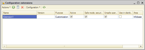
Fig. 518. Managing extensions in Designer
In general, you can access the commands for working with the configuration extension in the following ways:
-
Use the command bar commands of the Configuration extensions window.
-
Using the context menu of the selected extension in the Configuration extensions window.
-
Click Actions – Configuration in the window with a configuration extension.
The commands presented in these menus have the same meaning as those used for the main configuration. For more information, see Managing configurations.
Besides standard commands, theConfiguration extensions dialog box gives you access to the following special commands: Configuration – Check applicability and Actions – Check applicability for all. These commands will allow you to check the applicability of the current or all extensions in the current infobase before actually launching the application with the installed extensions. For example, you can import the extension from the file and check applicability. If the extension is not applicable in the current infobase, a list of aplicability issues. They will be displayed in Designer message window.
The extension applicability check checks all installed active extensions similarly to the check upon the client application stratup. The extension check also checks the following:
-
If the controlled extension properties match the values of the same properties of the extended configuration.
-
If the extended configuration contains all adopted objects present in the extension.
-
If the current extension will not have any conflicts (for example, by configuration object names and internal IDs):
- With an extended configuration if the command is called in the extension metadata tree (Actions
-
Configuration - Check applicability).
- With an extended configuration and all extensions applied before the current one if the command is called in the Configuration extensions dialog box (Configuration - Check applicability).
-
For extension methods with the&ChangeAndValidate annotation, checks whether the text of the extended method matches in the configuration and in the extension. This check does not lock the extension. If this check is not passed, the extension will be applied, but the method with the applicability error will not be extended.
The check list in both cases can differ depending on 1C:Enterprise platform version.
30.2.1.2. Creating an extension
When you create an extension, specify its name and synonym, and the prefix of the names of methods and objects to be created in the extension. This prefix will be automatically added to new reports, data processors, and subsystems that are created in the extension, as well as to event handlers that are created in the extension forms. You can see the prefix in the Name prefix configuration extension property.
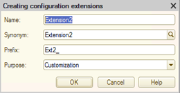
Fig. 519. New extension
When creating an extension, the following properties are automatically copied from the extended configuration: Default run mode, Use purposes, Main language, Interface compatibility mode, and Compatibility mode. The same properties are marked as controlled.
When you create an extension, you automatically create a role whose name is generated from the extension prefix and the DefaultRole word. For an extension prefixed with Ext1_, the automatically created role name will be Ext1_DefaultRole. Access to the native extension objects is automatically enabled in the created role. The new role is automatically set as value of the DefaultRoles property of the extension.
See also:
-
Extension properties (see Extension properties).
-
Access rights and extension (see Access rights).
30.2.1.3. Saving extensions to files
To install an extension to an application, you will need a configuration extenion file. To do this, select the required extension in the list of extensions in Designer and click Configuration – Save configuration to a file in the command bar of the Configuration extensions dialog box or the context menu of this window.
This will generate the file with the .cfe extension. This file will need to be applied to the application. For more information on the standard extension management function, see its help.
30.2.2. In 1C:Enterprise mode
To manage extensions in 1C:Enterprise mode, use the Configuration extensions management standard function. For more information on the standard function, see its help.
30.2.3. Deleting extensions
Interactive deletion of extensions (in Designer or in a client application) distinguishes between deletion of an extension that does not extend data and an extension that extends data. In the first case, you will see a standard confirmation question before uninstalling the extension.
In the second case, the deletion is performed in two steps. Firstly, clear the Active checkbox to disable the extension. Then, delete the extension from the infobase.
Deleting an extension from 1C:Enterprise language does not require additional control from the system (the ConfigurationExtension.Delete() method). However, the developer can perform all the necessary checks independently. To check if the extension is active, use the ConfigurationExtension.Active property. To check whether the extension extends data or not, use the ConfigurationExtension.ModifiesDataStructure() method.
30.3. Extension operations
30.3.1. Creating adopted objects
To adopt an object, use the Add to extension command of the configuration object context menu. After executing this command, an adopted object is created in the extension. When you create an adopted object, all parent objects are also adopted if they have not yet been adopted in this extension. Subordinate objects are not adopted. Let's explain the behavior with examples.
Suppose that the extended configuration contains the Goods catalog represented by a structure in fig. 520.
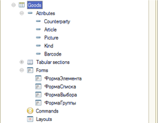
Fig. 520. Goods catalog structure
If you add the catalog to the extension, no subordinate objects will be added, as you can see on fig. 521.
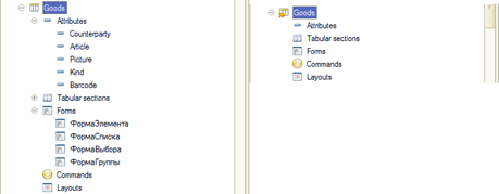
Fig. 521. After adding an object
Now, if you add the Goods catalog form (for example, an item form) when the catalog is already adopted, only the form will be adopted. If a form is adopted for an object that is not in the extension, the object itself and its form will be adopted. All the form items will also be adopted.
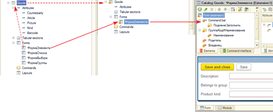
Fig. 522. After adding an object with parents
As you can see (fig. 522), only the added ItemForm form is adopted.
When you adopt a union type, the behavior depends on the characteristics of this type:
-
If a union type can include the Arbitrary type, then any union type for such attribute will be adopted as a union type consisting of a single Arbitrary type.
-
If a union type cannot include the Arbitrary type, then such union type will be adopted according to the following rules:
-
If a union type includes only primitive types, then all the types that form a union type will be adopted.
-
If a union type includes at least one reference type (CatalogRef, DocumentRef, and so on), then this type will be adopted as a simple AnyRef type.
-
However, it will be different if you add, for example, the main form attribute to the extension.
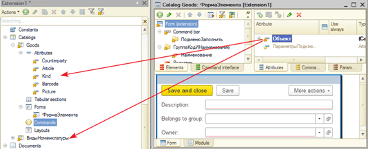
Fig. 523. Added an object with links
As the figure shows, all the Goods catalog attributes and all configuration objects specified as the catalog attribute types are added to the extension after adding the Object form attribute (the CatalogRef.Goods type).
When you adopt a parameterized command, the command parameter and the configuration object that determines the parameter type are not adopted. If necessary, independently adopt a configuration object (or objects, if the type is union) that determines the command parameter type and then specify this object as the parameter type of the adopted command.
30.3.2. Operations with adopted objects
Operations with an adopted object have some specifics.
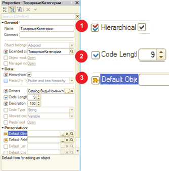
Fig. 524. Adopted object properties
An adopted object has only the properties which can be set as controlled, checked, or mutable ones. The option to set a property attribute is the second feature of the adopted object property panel. Various object property features are displayed differently in the property panel for the adopted object (fig. 524):
-
Controlled property. An extension will not be applicable if these properties are mismatched in the extension and the extended configuration. The following controlled properties are specified for the Goods catalog: Hierarchical and Available code length.
-
Property to check. A mismatch of such properties between the extension and the extended configuration will generate property mismatch warnings, but will not prevent the extension from being applied. The figure shows the following checked properties for the Goods catalog: Code length, Description length, and Code type.
-
Property to modify. You can see that the Main form property is marked as mutable one.
In the resulting object, the mutable property is recieved from the extension. If several extensions are applied to the infobase (or data area), the modifiable property will receive the value from the extension specified last in the list of extensions (see In 1C:Enterprise mode).
If the mutable property value is not specified, the system behaves the same as it does with the unspecified property value in the standard configuration (withour extensions). Thus, for example, if the Main report form configuration property is specified as modifiable, and the form itself is not specified, then the form automatically generated by 1C:Enterprise will be the main report form.
Keep in mind that the Name configuration object property is always a controlled attribute. If at the time the extension was created, the catalog had the Goods name in the extended configuration, and then it was renamed to Products, then the extension will stop operating until the Products name is also set for the adopted catalog in the extension. The same is true for the values of other controlled properties.
The issue of renamed extended configuration objects can make the extension support very difficult. To simplify the solution of this issue, the system offers to track the object correspondence not only by name, but also by internal ID of the configuration object type. To enable this feature, use the Support mapping to extended configuration objects by internal IDs extension property. It is enabled for new extensions automatically. If the feature is enabled, then the Extended configuration object property, which is automatically set to the controlled status, is filled in for each adopted configuration object (including the subordinated ones). When you rename an extended object, the extension will not be applied because the name of the object being a controlled property has changed.
However, in Designer, you can check the extension applicability. The test results will indicate the problem of the absence of the object with the previous name, and the system will offer several solutions (which can be applied to several selected lines in the applicability window). Depending on the situation, you can do different actions:
-
Rename and save match. The object is given the name of the object from the extended configuration with the internal ID of the type earlier saved in the Extended configuration object property if such object exists and the metadata types match.
-
Save name and change match. The internal ID of the extended configuration object with the same name as that of the adopted object is set for the Extended configuration object property.
-
Select match. The internal ID of the manually selected configuration object type is set for the Extended configuration object property.
-
Disable check. The Extended configuration object property is disabled.
-
Clear match. The Extended configuration object property internal value is set for the object. A property with such a value is not updated when the extension is saved.
-
Set value from configuration object. The extended object property value is set for the property.
-
Delete object. The object is deleted from the extension.
If several issues are selected for solution, then only those variants that are applicable to all selected issues will be offered for selection.
To comment on extension objects, use the Comment property of an extension object. The property is not multilingual. The comment is not used in the extension application process.
30.3.3. Creating native objects
You can create both adopted and native objects in the extension. Creating and editing native extension objects is no different from similar actions in an extended configuration. The uniqueness of native object names is checked:
-
When applying extensions: among extended configuration names and all extensions.
-
When developing an extension: among extended configuration names and the extension where the native object is created.
If, for example, there is a SearchInData data processor in an extended configuration, then no data processor with the same name can exist in any extension.
When creating a native object, this object gets the prefix that is set when the extension is created.
30.3.4. Blocking extensions
Since the list of extensions is the same for both access from Designer and access from 1C:Enterprise, the system does not allow you to perform mutually exclusive actions. In other words, if a window with an extension is open in Designer, it cannot be removed from the list of extensions in 1C:Enterprise mode. An extension, while writing to the infobase in 1C:Enterprise mode, in Designer is unavailable for any operations with it.
30.3.5. Shared extension development
Extensions can be developed using the configuration repository. Each extension is considered a separate configuration and a separate configuration repository is created for it. You cannot:
-
Store extensions in the same configuration repository as the extended configuration.
-
Store multiple extensions in a single configuration repository.
-
Apply an extended configuration to the extension repository and vice versa.
In general, operations with a configuration repository for an extension are no different from operations with a configuration repository for an extended configuration. The developer is provided with the ability to capture objects, place them into storage, generate reports on the storage, compare objects from the main configuration and the storage of the extension, and so on.
To access the extension operation commands, click Configuration – Configuration repository in the Configuration extensions window.
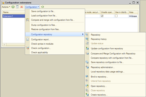
Fig. 525. Accessing commands for operating the configuration repository for extension
In the window with the extension metadata tree, commands for working with the storage are available in the context menu, similar to the main configuration tree.
See also:
- Configuration repository (see Distributed configuration development).
30.4. Extension objects
30.4.1. Extension properties
The configuration extension has a set of properties similar to the properties of the extended configuration. There are also special properties that only the configuration extension has or whose behavior differs from the behavior in the extended configuration. For a description of the Configuration extension purpose and Name prefix properties, see the brief feature description. The Maintain the mapping of extended configuration objects by inner IDs property is intended to make it easier for an extension developer to find issues that arise when an object in an extended configuration is renamed. For more information, see Operations with adopted objects.
To describe an extension, capabilities similar to an extended configuration are provided. For this, the extension has a set of properties:
-
Brief information and Detailed information allow you to specify an extension description.
-
Copyright allows you to specify information about the extension developer.
-
Vendor information address allows you to specify an URL where you can find more detailed information about the extension vendor.
-
Configuration information address allows you to specify an URL where you can find more detailed information about this extension.
You can also replace the following images of the main configuration: the main section picture, the logo, and the splash. Note the following features of this replacement:
-
Images from the configuration are completely replaced with images from the extension.
-
If several extensions replace the images, then one image will be used for each property. Such image will be an image from the last applied extension.
With the configuration extension, you can change the appearance of an extended configuration. For this, you can extend the Default style property. At the same time, you can both extend existing styles and style elements, and create your own styles and style elements in the extension. When extending style elements, you can change only the color value, but not the appearance of the style element.
The Default roles property allows you to specify the roles that will determine the availability of extension objects if there are no users in the extended configuration. The property is similar to the Default roles property of the extended configuration. The following set of restrictions are applied to the role added as the default extension role:
-
The role should not be adopted. Only a native role of the extension can act as the default role.
-
The role cannot grant access to adopted objects of the extension. The default extension role controls access only to the native extension objects.
The Configuration extension compatibility mode property is similar in purpose to the Compatibility mode property of the extended configuration. This property controls the capabilities that the system provides in the configuration extension. If a capability is used when editing an extension that is incompatible with the set value of the Configuration extension compatibility mode property, the infobase configuration will not be saved, and when attempting to perform this operation, a diagnostic message will be displayed explaining the reason for the impossibility to perform the operation. For details on the system operation in a particular version compatibility mode, see Extension compatibility mode specifics.
See also:
-
Brief feature description (see Brief feature description).
-
Default extended configuration roles (see Specifying general properties).
-
Extended configuration compatibility mode (see Specifying compatibility properties).
30.4.2. Modules
30.4.2.1. General information
With 1C:Enterprise, you an extend almost any module related to the managed application. Extending global server modules is not possible. Also keep in mind that extending a privileged common module will run in non-privileged mode (unless otherwise allowed by the security profile). In addition, you can create native common modules that cannot be privileged and global server ones. Operations with native common module in an extension are no different from operations with a common module in a regular configuration.
Operations with an extended module have significant peculiarities that will be covered in this section.
When you develop an extending module, keep in mind that this module will be in the same namespace as the extended module. In this regard, you can use the extended context (variables and methods) directly from the extending module. It is also worth noting that export methods and variables created in the extension are automatically included in the public context of the extended module.
In the extending module, you can:
-
Create native methods and variables (if the extended module allows it).
-
Assign native handlers to events that are not handled in the extended configuration.
-
Intercept any extended module method (including event handler methods), with the possibility to:
-
Completely replace the original method with the native one.
-
Create methods that will be called before or after an extended method.
-
Creating a native method or variable in an extending module is no different from creating a method or variable in an extended configuration, when not using extensions. However, when you create native methods or variables, it is recommended that you prefix their names so that the method or variable attribution to this or that extension is uniquely identified, as well as avoid a name conflict with an extended configuration.
In an extension, you cannot extend the module body and variable area, but you can define your own variables and write your own module body. The body of the extension module will be executed after the module of the extended configuration.
Interception of extended configuration methods (including the assignment of handlers) is implemented using a special annotation feature (see Annotations). There are several ways to intercept a method call, which allows you to implement almost any scheme for executing extensible and extending program code.
In general, an annotated method from an extension module is as follows:
&Annotation("MethodName")
Procedure Prefix_Name()
// method text
EndProcedureIn this example, Annotation is a possible annotation, MethodName is the name of a method to be extended, and PrefixName is the name of an extending method. Prefix is the extension prefix to be specified for all the extension methods. Both a procedure and a function can be extended. The name of the extending method must follow the usual rules for naming procedures and functions. In particular, it must be unique.
If the extended method contains any parameters, then:
-
All extending methods must have exactly the same description as the extended method, up to the Value keywords in method parameter descriptions.
-
Parameter values are shared between all extending methods from all extensions and the extended method itself. This means that if any extending method changes the value of a parameter, all the methods that get control after this method will receive the modified value of this parameter.
-
It does not make sense to specify default values for the parameters of the extended method in the extending method. Default values will be determined from the description of the extended method.
Also note that if an event handler is extended, the extending method will run before the "extended" event subscriptions (see Event subscriptions).
If the module is extended, then before executing the resulting program code (the extended configuration and all connected extensions), the following actions are performed:
-
Perform a syntax check for the extended configuration module. If an error occurs during the check, the user receives an error message and the current action is terminated.
-
Sequentially perform a syntax check for extending modules from all the applied extensions. If an error occurs during the check (for example, an extending module uses a method missing in the extended configuration), the user receives an error message and the current action is terminated.
-
Check the applicability of extending modules: the extended method is searched for each extending method, name mapping and parameters are checked. If the applicability check fails, a specific method extension using a particular extension is not applied, and a warning message is displayed to the user.
-
If all checks are successful, all modules are compiled and the object that contains these modules is ready for use.
From the above sequence of actions, two conclusions follow:
-
If a syntax check detects errors for modules that are executed upon the application startup (an application module, a session module), these errors will not allow you to start the application.
-
If a syntax check detects errors upon object initialization (for example, when attempting to open a catalog form), the object will be unavailable for use, but the application will not be terminated. The check is performed upon each attempt to use a configuration object.
30.4.2.2. Extension methods
30.4.2.2.1. Execution before the extended method (Before annotation)
If a method is annotated in this way, it means that the extension method will be executed first, and then the extended method will run.
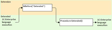
Fig. 526. "Before" execution scheme
30.4.2.2.2. Execution after the extended method (After annotation)
If a method is annotated in this way, it means that the extended method will be executed first, and then the extension method will run.
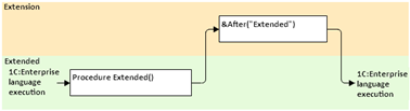
Fig. 527. "After" execution scheme
30.4.2.2.3. Framing an extended method (Before and After annotations)
If the extended module creates extended methods that are annotated with Before and After, this means that the method annotated with Before will be called first, then the extended method, and then the extension method annotated with After.

Fig. 528. "Before" and "After" execution scheme
30.4.2.2.4. Method replacement (Around annotation)
Intercepting a method call implies a situation when a method created in an extension completely replaces the extended method. In other words, calling the extended configuration method will execute the extension method. The name of the replaced method is specified as a parameter of the annotation. It is recommended that you use this method only when it is not possible to use other methods of extending methods.
Only this method of extension can be used for extended functions.
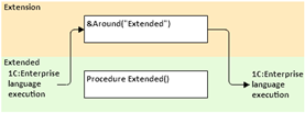
Fig. 529. "Around" execution scheme
To be able to modify the result of an extended method, use the ProceedWithCall() global context method. The actual parameters passed to the extended method should be specified as method parameters.
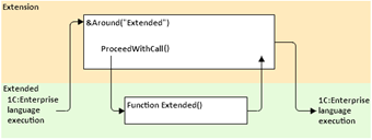
Fig. 530. "Around" execution scheme with ProceedWithCall()
The initial version of the text will be as follows:
&Around("Extended")
Procedure Ext1_Extending(Param1, Param2)
// method text
ProceedWithCall(Param1, Param2);
// method text
EndProcedure30.4.2.2.5. Method spot modification in extension (ChangeAndValidate annotation)
This extension method allows spot modification of the extended module text. The entire module is copied to the extension during adoption. Then, use the #Insert … #EndInsert and #Delete … #EndDelete preprocessor commands to mark text fragments to be added to the extended module and, accordingly, to be deleted from it.
Consider an example. Let's suppose we have a method of exponentiation by simple multiplication. When writing the method, the configuration developer made a mistake and wrote the addition operation instead of multiplication. The result is the following method:
Function Exponentiation(Basis, Exponent) Export
Result = 1;
For Index = 1 By Exponent Do
Result = Result + Basis;
EndDo;
Return Result;
EndFunctionWe detected the mistake on the spot. To fix the error, you can use the ChangeAndValidate annotation. The corrected method in the extension will look as follows:
ChangeAndValidate("Exponentiation")
Function Ext1_Exponentiation(Basis, Exponent)
Result = 1;
For Index = 1 By Exponent Do
#Delete
Result = Result + Basis;
#EndDelete
#Insert
Result = Result * Basis;
#EndInsert
EndDo;
Return Result;
EndFunctionAs soon as the configuration developer corrects the error (and the extended configuration is updated), the extension stops running with troubleshooting of the following type:
Extension1:
Normal: An error occurred when applying the "Extension1
CommonModule.CommonModule1.Module" module. The module text for the
Exponentiation method has changed.The applicability check ignores spaces and tabs at the beginning and at the end of each method string and empty strings (or strings containing only spaces and tabs) in the method body.
If the extension applicability check is performed in the Designer, the result of the check will be an error message and the possibility to restore mapping to configuration method.
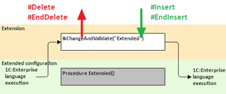
Fig. 531. Applicability error for the ChangeAndValidate annotation
To restore, click the hyperlink in the Action column. As a result, the trilateral module merging form will appear. The merging will include:
-
Original method text that was in the extended configuration. The file will be named MethodNameRESTORED.
-
Method text from the extension (with preprocessor directives). The file will be named ExtensionPrefixMethodName.
-
Method text that is currently in the extended configuration. The file will be named NameMethod.
The result of the merging will be placed in the extension. If the configuration is not configured to use an external program for trilateral merging, it will be impossible to restore the compliance with the configuration method. Specify the external program required for merging in the "Merge using an external program" mode property in the Designer parameter settings dialog box (Main menu – Service – Parameters – Comparison/merging – Modules group – Supported configuration update group). This property should not be set to the Not used value.
When developing a method with the ChangeAndValidate annotation, the syntax check (in the Designer) will ignore all errors of the "variable is not defined" type in all areas of the method except the #Insert … #EndInsert area. This will reduce the number of adoptions when developing methods of spot modification of the configuration.
Now let's take a closer look at how this method of extension works.
The method is completely copied to the extension during adoption, but marked with an annotation. Then, mark the code to be deleted from the extension with the #Delete ... EndDelete preprocessor directives (you cannot just remove the "incorrect" code from the module in the extension). It will allow the system to control the equivalence between the extended method and the method in the extension. Place the code to insert into the extended method inside the #Insert … #EndInsert preprocessor directives (it is not enough to simply insert the "correct" code into the appropriate places in the method).
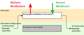
Fig. 532. "ChangeAndValidate" execution scheme
From the point of view of the configuration, we can say that the method extended with the ChangeAndValidate annotation fully replaces the extended configuration method. The remaining directives will be called relative to the corrected method. So, if another extension is used in the configuration and the same method (in the example above, it is Exponentiation()) is extended using the Around annotation (and the ProceedWithCall() method), the system will extend the method resulting from the modification of the extended method from the extension using the ChangeAndValidate annotation.
It follows that each configuration method can be extended using the ChangeAndValidate annotation exactly once. If one more extension extended by the same method with the ChangeAndValidate annotation is attached to the configuration, this extension will fail the applicability test.
See also:
- Setting up comparison/merging parameters (see Comparison/merging).
30.4.2.3. Module editing
In general, editing a module in an extension does not differ much from editing a module in an extended configuration or a module in a configuration where there are no extensions at all (for more information, see Editing modules). The main differences include the process of adopting a method from any module of the extended configuration.
To add a method to an extension, place the cursor in the required method (including the line with the name of the method) and select the Add to extension command. If one extension is opened in Designer when this command is executed, then this extension will be used. In all other cases, you will be prompted to select from the extensions that have been added to this infobase.
Upon executing the Add to extension command, the following happens:
-
If the object from whose module the method is added is absent in the selected extension, this object is automatically added to the extension.
-
If a method is extended from a module other than the form module:
-
The developer is offered to select an annotation for the method (Before, After, Around, or ChangeAndValidate). In this case, the method extensions that already exist in the extension are highlighted in bold.
-
If an existing method is selected in the extension, the transition to this method is performed. In this case, you can adjust the method declaration if it has become different from the extended method.
-
If a nonexistent extension method is chosen, a new method will be created in the extension, which will be preceded by the appropriate annotation.
-
The Before and After annotations are unavailable for functions.
-
The following annotations are unavailable for a procedure:
-
The Around and ChangeAndValidate annotations if there already are methods with the Before or After annotations.
-
Another annotation if there already is a method with the Around annotation.
-
-
-
If a method is extended from a form module:
-
If the extended method is a handler for one event or command, you are prompted to choose how to perform the selected method: as an extension for an event/command handler or as an extension of a standard method.
-
If the extended method is a handler for multiple events or commands, a warning will be generated stating that this method cannot be extended as an event/command handler, and it will be extended only as a standard method. You will then be prompted to choose how to extend the method.
-
For a standard method that is not an event handler, the method will be extended using annotations.
-
Note that if an extended method is framed by preprocessor commands, these commands will not be transferred to the extension.
When checking the conformity of the extended method and the extension method descriptions, the following characteristics of the methods are verified:
-
The number of parameters and the flag of passing parameters "by value" (the Value keyword).
-
A method is a procedure or a function. If the method definition changes from a procedure to a function, and before that the procedure was extended using the Before/After annotations, the annotation will be replaced with the Around annotation.
-
If there are several methods with the same name in the extension module, but which are framed with different preprocessor commands, then the first method from the list of such methods will be updated first in the extension.
Another feature of editing a module in an extension is that it is possible to go to the extended method directly from the extension. To do this, place the cursor on the name of the extended method in the annotation, and then use the standard Go to definition editor command.
30.4.2.4. Interaction of several extensions
When developing extensions, you should proceed from the following assumptions:
-
Develop an extension as a standalone product, not relying on the presence or absence of other extensions.
-
You can attach more than one extension that extends the same extended configuration object at the same time.
-
The order of module execution in the resulting configuration is determined by the order in which the extensions are registered in the infobase of the extended system. The extension that was last registered is used first.
-
An unhandled exception that is thrown in any extension (or an extended configuration) interrupts the execution of the entire extension method chain and is distributed in an extended configuration.
When considering the interaction of extensions and an extended configuration, an example of two extensions (Extension1 and Extension2) registered in the extended system in the specified order will be used. In this case, the earlier the extension is registered, the fewer extensions are between this extension and the extended configuration. So, Extension1 will extend the directly extended configuration, and Extension2 will extend the configuration that is the combination of Extension1 and the original extended configuration. Thus, the extended configuration is at the very bottom of this layered structure, from where the execution of 1C:Enterprise language always begins.
Next, we will consider several examples of how the resulting configuration operates with different extension methods.
Example 1
If both extensions frame the extended method in the same way (Before and After annotations), the execution scheme of the 1C:Enterprise language would appear as follows:
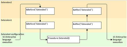
Fig. 533. Interaction scheme. Example 1
When attempting to call the Extended() method (in the main configuration), 1C:Enterprise language will be executed in the following order:
-
The method annotated Before("Extended") from Extension2 will be called.
-
Then, the method annotated Before("Extended") from Extension1 will be called.
-
Then the Extended() method from the extended configuration will be called.
-
Then, in reverse order (relative to the list of extensions, that is, Extension1 and Extension2), the methods marked with the After("Extended") annotations will be called.
First, the application calls extension methods that the developer marked as to be called before executing the extended method. Then it executes the extended method itself. Finally, the application calls methods that the developer marked as to be called after executing the extended method.
Example 2
If the extended method is fully intercepted in each extension, the execution scheme will look like this:
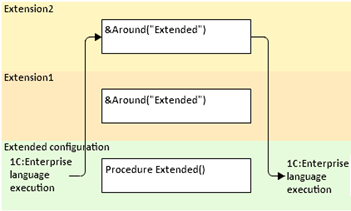
Fig. 534. Interaction scheme. Example 2
It happened because the method marked with the Around annotation completely replaces the extended method. Note that if you change the registration order of extensions in this example (the first one being Extension2 and the last one being Extension1), only the Extension1 method will be executed.
Due to such behavior of the "replacing" extension method, it is recommended that you avoid situations when an extended configuration method is extended with a replacement (the Around annotation) in more than one extension running at the same time. In other words, if in the Document1 document module of the extension, the Posting event handler is replaced, then it is recommended that you avoid situations when at least one more extension running in the infobase, which somehow intercepts the Posting event handler in the Document1 document. However, if the replacing extension method contains an unconditional call of the ProceedWithCall() method, several extensions with this extension method can exist at the same time.
30.4.2.5. Security profile and extension
The fact that an extension is successfully attached to an extended configuration does not mean that all the extension methods that are in the extension will be executed. You can change the performance of extension methods with the settings of the security profile.
If the application runs in a file mode or in a client/server mode without security profiles, then when connecting the extension:
-
In normal 1C:Enterprise language execution mode, you can extend both client and server methods. No restriction on the location of methods.
-
In safe 1C:Enterprise language execution mode, only client methods and server form handlers that are set via the property panel will be extended. The extension will not be applied to other server methods (annotated server methods of form modules and server common modules).
The ability to extend server common modules in a client/server mode is regulated by the security profile.
30.4.3. Forms
30.4.3.1. General information
Only form items are adopted when a form is adopted. Form attributes, commands, and parameters are displayed in the extension form editor, but they are not adopted. An adopted form looks exactly like this form looks in the extended configuration at the time it is added to the extension. The adopted form module contains no methods. Designer "saves" the form in the extension when the form is added. Further below, this form will be called saved.
Until the developer changes the properties of the adopted form items, an item representation is determined by the extended configuration. To change item properties in the adopted form, no extra actions needed. To change the properties of a form attribute, command, or parameter, add the relative item to the extension (similar to any other configuration item).
Form components are updated the following way:
-
If an attribute, parameter, or command is not added to the extension, changes of these components in the extended configuration are automatically displayed in the extension.
-
Attributes, parameters, and commands added to the extended configuration are automatically displayed in the extension.
-
If form item properties are changed in the extended configuration, such changes will be displayed in the extension only after the saved form update. In this case, the resulting form (in 1C:Enterprise mode) will be generated considering all changes in the extended configuration.
-
Attributes, parameters, and commands deleted from the extended configuration will be automatically deleted from the extension without waiting for the saved form update. If the deleted form component is added to the extension, it will remain in the extension (until the saved form is updated), but it will be absent from the resulting form (in 1C:Enterprise mode).
-
If properties of any form object added to the extension are changed, the system will perform a three-way comparison to get a resulting object. For more information, see Building the resulting form.
30.4.3.2. Form editor
The form editor displays the extension of the form being edited. Extension name is displayed in square brackets in the form editor title.
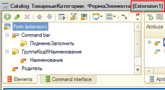
Fig. 535. Extension name display
Click Update form extension on the form editor command bar if you want to transfer changes and additions in the extended configuration after creating the form extension to the extension.
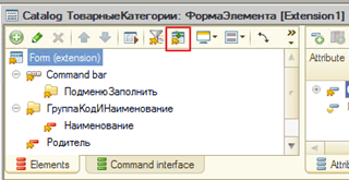
Fig. 536. Update form extension
For the description of actions that will be performed on the form components after executing the Update form extension command, see General information.
Click Show only changed items on the form editor command bar to hide form items whose properties remained unchanged (in relation to the extended form).
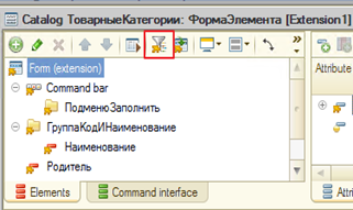
Fig. 537. Show only changed items
If you click the button, the form item list will show only the form items whose properties are changed in the extension form. If this button is released, all form items are displayed.
If the composition of form items is changed in the extended form, this fact will be detected in the extension form editor, and the user will be prompted to update the form in the extension.

Fig. 538. Update form in extension
Such a prompt will appear both upon first opening the extension form editor and during operation (if the extended configuration form is changed in its window). A similar offer will be made if the form item structure is changed in the extension itself.
The display of form components also helps determine the state of the form component.
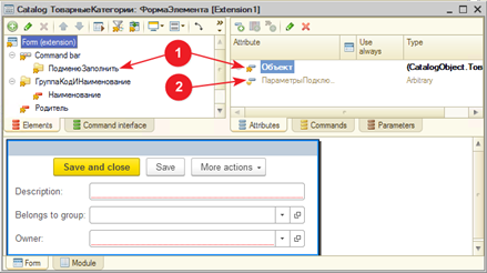
Fig. 539. Component statuses
fig. 539 shows the different states of the form components. The numbers on the drawing mean the following:
-
Form components adopted into the extension. Form items are always adopted. Attributes, commands, and parameters must be adopted as needed.
-
Form components not adopted into the extension. These components act as "references" to the components of the extended form. To change the property values of such components, add them to the extension first.
For form items adopted into an extension, you can select only properties that changed in the extension. For this purpose, there is a Show only changed button in the property panel of the adopted form item.
Fig. 540. Show only changed form item properties
When the button is pressed, the properties panel shows only those properties of the form item that have been changed in the extension. If a form item is not covered by the extension, this button is unavailable in the command bar.
Form attributes, commands, and parameters can be both added to the extension and "removed" from it. To "delete", press the Del button on the relative form component. In this case, the component status will change to that shown by number 2 in fig. 539. In this case, all changes made in the extension will be lost. After the "deletion", the behavior returns to the behavior set for this component in the extended configuration. This behavior does not cover form items. Deleting adopted form items and returning form items to the settings "as in the extended configuration" are not supported.
To remove an item from the resulting form, set the Enabled property to False (clear the checkbox) for such item in the extension.
30.4.3.3. Form modules
Extending a form module is somewhat different from extending any other module. This section covers the module extension features in the form module.
The first feature is that you should create handlers in an extending form using the property panel of the relative form item (form, item, or command). Trying to create a handler, the Designer will clarify when the created handler should be called and how it will be created.
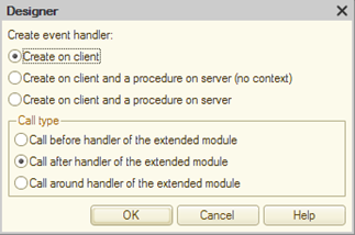
Fig. 541. Handler extension
At the same time, next to the name of the extending handler in the property palette, a picture will appear that indicate the type of extension. Also, if the Before or After extension type is selected, another input field will be automatically displayed to specify a paired extending method. If an extending method with the Before extension type is created, another field will be created for the extending method with the After extension type, and vice versa. For a replacement handler (with the Around extension type), no similar behavior will occur.

Fig. 542. Handler designations
If you need to change the type of the extending handler, delete the existing handler and recreate it.
In the code of the event handler with the After extension type, it is prohibited to change the values of the Cancel (for all events with such a formal parameter), Execute (for the DragStart event), and CancelEdit (for the OnEditEnd event) parameters. In handlers with the Before extension type, handlers in the following extensions and a handler in extended form will not be called in the following cases:
-
setting Fail parameter to True;
-
setting Execution parameter to False (for DragStart event);
-
Set the CancelEdit parameter to True (for the OnEditEnd event handlers).
The next feature is that the managed form editor creates extending handlers without using annotations.
See also:
- Extending non-form modules (see Modules).
30.4.3.4. Building the resulting form
In 1C:Enterprise mode, the resulting object is generated by combining the extended object and all extending objects. The combining process is as follows:
-
The extended configuration is combined with the first (in order of registration) extension.
-
The combining is repeated for each subsequent registered extension, where the result of the previous combining operation is used as the extended configuration. In terms of each next combining operation, the result of the previous combining operation will be considered an extended object.
In the process of combining each component (item, attribute, parameter, or command) of the managed form, changes in the extended and extending forms are analyzed relative to the saved one. Based on the analysis results, a decision is made about which add-in will be displayed in the resulting form:
-
If there are no changes, the component is taken from the extended object.
-
If there is a change only in the extended form, the component is taken from the extended form.
-
If there is a change only in the extending form, the component is taken from the extending form.
-
If there is a change in both the extended form and the extending form, the component is taken from the extending form.
The mapping of client application form components is performed by the name of the corresponding item.
The above mode is not applied:
-
To conditional appearance. In this case, conditional appearance items are combined from the extended form and all the extending forms similar to merging configurations.
-
To generate the command interface of the resulting form, add command interface elements from the extending form to the command interface of the extended form. In this case, it is possible that the form will contain several commands with the same presentation, since they are generated by the commands from different extensions, but with the same presentation.
When determining the order of the resulting managed form items, the system first determines whether the items can be arranged without placement conflicts. If it is possible, then the order of the resulting form items is determined as follows:
-
Form items added to the top of the list (whether in the extension or in the extended configuration) will remain at the top of the list regardless of the order of the remaining items. Form items from the extensions will be placed first (in the order of appearance), followed by the ones from the extended configuration.
-
Form items added to the bottom of the list (whether in the extension or in the extended configuration) will remain at the bottom of the list regardless of the order of the remaining items. Form items from the extended configuration will be placed first, followed by the ones from the extensions (in the order of appearance).
-
You can also place other form items next to an extended form item. To do this, in the extension, create a group to place the item of the extended form and those items to be located next to it. Then, when changing the location of the original item in the extended form, the whole group where this item was placed will be located in the resulting form in the new location.
If the order cannot be defined without conflicts, the following algorithm is used:
-
The source is the list of extension items in the order that is set in the extension.
-
To determine the position of an item added in the extended configuration, a search is performed for an existing item in the saved configuration located before the added item(in the order of the extended configuration):
-
In accordance with the order of the items in the extension, it is determined which item is next (the existing one or the one added by the extension):
-
If the existing item, the main configuration item is added after the found one.
-
If an item or items are added by the extension, then the extended configuration item is added after them.
-
-
If multiple items were added to the extended configuration, subsequent items are added after the previous ones, even if the previous ones have already been added by the extension.
-
If the item after which the items were added is not found in the extension (for example, it has been deleted), then the previous existing one is searched for in the order of the main configuration. If the search reaches the top of the item list, then the new item (or group of new items) is added to the top of the resulting list, but after the new extension items added to the top of the list.
-
-
New extended configuration items added to the top of the list are added immediately after the new items of the extension added to the top of the list.
-
New extended configuration items added to the bottom of the list are added before the new items of the extension added to the bottom of the list.
-
If, when adding, it turns out that the item has already been added by the extension, then this item is skipped.
-
Items that were deleted in the main configuration compared to the saved version are deleted.
30.4.4. Form command interface
The form command interface is supplemented with extension command interfaces. Commands added to the form command interface manually will be displayed after the extended configuration commands (in 1C:Enterprise mode). The consequence is that several commands with the same presentation can simultaneously exist in the resulting form.
Deleting an extended configuration command is not possible.
Keep in mind that in the form editor in Designer, the developer will not see command interface fragments that are provided by the extended configuration.
30.4.5. Object forms
For configuration objects, you can change the main and auxiliary forms of adopted configuration objects. To do this, in the extension, create a form that will replace the existing form of the configuration object, then mark the configuration property that describes the replaced form as a modified attribute and specify the new form in this attribute. To change the configuration properties associated with forms (Main report form, Main search form, and other properties), there is no need to adopt the root item of the configuration tree. It is enough to use the properties of the extension root item.
30.4.6. Subsystems
Subsystem can be either an adopted or a native extension object.
A native subsystem of the extension can include both native extension objects and adopted objects.
Configuration objects that were added to the structure of the adopted subsystem in the extended configuration cannot be removed from this subsystem. But other objects can be added to the structure of the adopted subsystem: both native and adopted (relative to the extension). For an adopted subsystem, you can create native subordinate subsystems.
For adopted objects, it is possible to change the subsystem picture by changing the modifiable Picture attribute.
30.4.7. Access rights
30.4.7.1. General information
Note. Important. The following behavior is relevant only if the Configuration extension compatibility mode extension property is set to Version 8.3.14 and later (including Do not use in version 8.3.14).
Using the configuration extension, it is possible to extend an existing role, as well as to create your own role in the extension.
In the simplest case, when roles are set neither in the extended configuration nor in the extension, the user can access all objects of the main configuration and all extension objects. The absence of roles is a kind of degenerated situation for an extension because a role granting rights to all native extension objects is created automatically when you create an extension.
When an extension is attached to an infobase, you can select the Force default roles for all users checkbox. This checkbox operates as follows:
-
If the checkbox is selected and the DefaultRoles property is set, then the minimum set of rights will be defined by the roles specified in the DefaultRoles property. In this case, the administrator can extend the set of roles of a certain user with other extension roles (not included in the default extension roles).
-
If the checkbox is cleared and the DefaultRoles property is set in the extension, then the minimum set of rights will be defined by the roles specified in the DefaultRoles property only if there are no users in the configuration to which the extension is attached.
-
In all other cases, the rights to the extension objects will be defined by the system administrator, who must provide each user with access to the extension objects (using Designer or other tools)
Note that if the Force default roles for all users property is set when the extension is attached it will be impossible to deprive the users of the rights granted by the default roles. To set the Force default roles for all users property, you must have the configuration extension administration right.
If there are no native roles in the extension, the accessibility of the extension objects can be managed using the extended configuration roles.
The accessibility of the native extension objects in the resulting configuration is determined by the status of the Set rights for new objects property in the extended configuration role. It means that the resulting configuration considers all native extension objects as its new objects. Thus, the native extension objects will be accessible in the native roles in which the Set rights for new objects role property is set.
The Set rights for attributes and tables by default role checkbox of the extended configuration ensures that attributes and tables are available in native extension objects. In roles where the checkbox is selected, native extension objects will contain all rights to attributes and tables.
Based on the above information, we can define the following general scheme for working with access rights:
-
Adopt a role only when you need to change access rights (or data access restrictions) relative to the extended configuration.
-
In an extension without native roles, access to the extension object is defined by the extended configuration role settings.
-
Native extension roles define the rights for native and adopted extension objects. A native extension role cannot change the rights to extended configuration objects that are not added to the extension.
Operations with adopted and native roles will be covered in the subsequent sections.
See also:
-
Setting up user access rights.
-
Access rights.
30.4.7.2. Adopted roles
30.4.7.2.1. General information
For an adopted role, you can change the access rights specified for the extended configuration objects. You can change not only the access rights themselves, but also data access restrictions. You can also create and use data access restriction templates in an adopted role object. An adopted role does not provide the option to change access rights that are set for the root configuration object (administrative rights, the option to use a particular client application, and so on).
In an adopted role, all rights, by default, correspond to the rights from the extended configuration. This corresponds to a special checkbox value in the rights setting. However, you can set or reset any right. Thus, using an adopted role, you can both extend and narrow the user rights.
The data access restrictions specified in the extension will only be used if the rights in the adopted role are explicitly specified for the access right. In this case, the data access restrictions from the extension will completely replace the data access restrictions from the extended configuration (for the given right and role). If the access right is adopted from the extended configuration, the data access restrictions specified in the extension will not be used.
30.4.7.2.2. Editing
When you edit an adopted role, you can set the "third state" for the access right: use the value from the extended role.
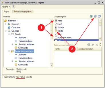
Fig. 543. Adopted role editor
The rights changed in the extensions are marked with number 1 and the rights set by the extended role are marked with number 2 in this figure.
An adopted role provides the ability to manage automatic rights assignment only for the extension's own objects. For this, use the Set rights for new native objects checkbox.
The Set rights for attributes and tables by default property of the extended role is responsible for the rights to attributes and tables of extension objects. To enable the option to set independent rights to subordinate configuration objects in the extended role, select the Independent rights for subordinate objects checkbox of the extended role. In other words, the rights to attributes and tables, as well as the option to set independent rights to subordinate attributes depend on the extended role settings.
30.4.7.3. Native roles
A native role does not allow you to set access rights that are bound to the root configuration item (administrative rights, use of client applications, use of exclusive mode, and so on). Native extension roles can be added to infobase users both interactively and using 1C:Enterprise language. When an extension is deleted, all of its native roles are removed from the lists of user roles.
A user whose roles are supplemented by the extension are viewed in the Designer with a special icon.
The native role that is automatically created when you create an extension can be arbitrarily renamed or deleted. If an extension prefix is changed, the automatically created role remaining is suggested if the following conditions are met:
-
The role name is formed as <ExtensionPrefix>DefaultRole.
-
The role with such (as above) name is set in the DefaultRoles extension property.
-
The extension is missing the <ExtensionNewPrefix>DefaultRole role.
Actually, it is offered to replace the <ExtensionOldPrefix>DefaultRole role name with <ExtensionNewPrefix>DefaultRole. The system imposes no restrictions on modification of an automatically created native role.
To edit a native extension role, use a separate editor. Its appearance and options are similar to that of the extended configuration role editor. However, it has some differences both in the structure of edited rights (due to the extension specifics) and in the role checkbox behavior.
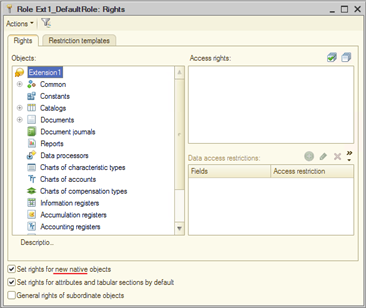
Fig. 544. Native role editor
The Set rights for new native objects checkbox is applied only to native extension objects.
The Set rights for attributes and tables by default checkbox provides (if selected) full rights to attributes and tables for both native extension objects and extended configuration objects. This checkbox also grants rights to attributes and tables added to the resulting configuration by other extensions.
The Independent rights of subordinate objects checkbox operates exactly the same as the same checkbox in the configuration role.
When an extension becomes inactive (as a result of detection of applicability issues), the native extension role continues to be available in the InfoBaseUser.Roles collection as a normal configuration object. Such a role can be added or removed from the list of roles of any user of the infobase. However, the AccessRight() function for such a role will always return False. If roles are received for a user from another data area (see Data separation feature), all roles added by extensions become invisible (they cannot be received, but they are not deleted when the user is saved).
When developing extensions that do not contain adopted objects, it is recommended that you adhere to the following guidelines for managing access rights to extension objects:
-
If the extension is small and does not involve role-based access the extension sections, an automatically created default role is enough. This role will grant access to all extension objects.
-
If the extension assumes role-based access to the extension sections (for example, an extension for generating and sending reports, where all users can generate a report but the responsible user must send it), it is recommended that you specify the rights for most users in the default role(s). The administrator must explicitly specify the role of the responsible user (who will send reports).
-
if the extension is attached with the Use default roles for all users checkbox selected, pay special attention to the rights granted by the roles included in the DefaultRoles extension properties. This is because all infobase users will get access in accordance with the rights of the default role(s).
-
If you need to grant rights to certain extension objects selectively, not to all users, it is recommended that you:
-
Create a separate role for such extension objects.
-
Do not specify this role in the DefaultRole structure.
-
Exclude access to "private" extension objects from the roles specified in the DefaultRoles property.
-
See also:
- Creating an extension.
30.4.7.4. Extending user rights and security profiles
Changing access rights for objects of an extended configuration depends on the infobase mode (see Operating modes):
-
If the extension is connected in safe mode in the file version, the ability to extend access rights to the native objects of the extended configuration is not supported. You can only restrict access rights.
-
In client/server mode, changing access rights is regulated by the presence of a security profile and its settings:
-
If the application operates without using a security profile, then role extension is not allowed.
-
If the application operates using a security profile, then access rights can be restricted in any case, and access rights can be extended only if the security profile is configured accordingly.
-
If the checkbox for access rights extension is selected in the properties of the security profile (in the Full access is allowed group), then you can extend access rights for any object of the extended configuration.
If this checkbox is cleared, then you cannot extend access rights. If the Roles that restrict the extension of access rights security profile property is filled in (roles are separated with a semicolon ";"), then the system operates as follows: a role from the configuration extension can extend the access right only if an extended access right is set in at least one of the roles from the Roles that restrict the extension of access rights security profile property. It is not necessary for the roles listed in the security profile property to be used for users of the application infobase. An example of this behavior will be discussed below.
- For native extension objects, access rights are granted in accordance with the settings of native or adopted extension roles, without collaborating with the security profile. This behavior is independent of the security profile settings.
Let's look at an example of the access right extension. Suppose there is an Invoice document in the configuration. In the extension, you need to extend the Read access right. To do this, use the SellerExtension extension role. The extended configuration also contains the SellerTemplate1 and SellerTemplate2 roles. The Roles that restrict the extension of access rights security profile property contains both roles: SellerTemplate1 and SellerTemplate2.
Example 1
In the extended configuration, the Read right for the Invoice document is specified as follows:
-
SellerTemplate1. The Read right is allowed.
-
SellerTemplate2. The Read right is prohibited.
In this case, the process works as follows: at least one of the roles specified in the Roles that restrict extension of access rights property has the Read right allowed (this is the SellerTemplate1 role). This means that a role from the SellerExtension extension can grant the Read right to the Invoice document.
Example 2
In the extended configuration, the Read right for the Invoice document is specified as follows:
-
SellerTemplate1. The Read right is prohibited.
-
SellerTemplate2. The Read right is prohibited.
In this case, the process works as follows: none of the roles from the list of roles specified in the Roles that restrict extension of access rights property provides the Read right. This means that a role from the SellerExtension extension can't grant the Read right to the Invoice document.
In other words, the algorithm that determines whether access rights can be extended from an extension is as follows: the state of required access right from all the roles listed in the Roles that restrict the extension of access rights property is combined "by OR". The result of addition "by AND" is combined with the right from the extension role.
30.4.8. Reports and data processors
Creating a new report or data processor does not differ from that in a configuration that does not contain extensions (see Reports and data processors). At the same time, you can extend existing forms of reports or data processors in the configuration you're extending. To do it, adopt the required object (see Creating adopted objects).
To create object attributes, tables, and table attributes is possible for an adopted object. Operation with these objects does not differ from that in a configuration that does not contain extensions.
For the Report adopted object, it is possible to override the main data composition schema. To do this, add a report to the extension, then mark the Main data composition schema property as changeable (see Operations with adopted objects), and then create the data composition schema for the report. If you need to change (rather than recreate) the data composition schema of an adopted report, it is recommended that you copy the data composition schema from the main configuration to the extension, specify this schema as the main one in the adopted report, and then upgrade this schema. Adopt objects included in the data composition schema manually.
30.4.9. XDTO packages
An XDTO package can be either an adopted or a native extension object.
You can adopt not only the entire package, but also some part of this package if the entire XDTO package is not required for the normal operation of the extension. If an adopted item already exists in the extension, the user is prompted to update it.
The following properties are transferred when adopting:
-
All set item properties, including list and aggregate properties.
-
All set properties of the created parent items, except for list and aggregate properties.
The Namespace URI package property will be obtained from the extension when connecting the extension. If an XDTO package is extended by multiple extensions, the Namespace URI property of the extended object will be determined by the last extension in the list. The same behavior will be with the XDTO package: the structure will be completely obtained from the extension. If a package is expanded in several extensions, the package structure will be determined by the last extension in the list.
The package structure and the Namespace URI property must either be simultaneously modified in the extension, or one item of the package can be modified while the other is controlled.
30.4.10. Web services
The adopted Web service has the ability to expand the list of XDTO packages whose types can be used as return value types for web service operations and operation parameter types (the XDTO packages property). When extensions are connected, the XDTO packages property of the extended web service is supplemented with a list of packages from the modified identically named property of the adopted web service.
You can publish a native extension web service in two ways:
-
Unconditional permission to use any web service from any connected extension. To do this, when publishing, use the checkbox of the Publish the web services extension by default publish dialog box or the similar publishExtensionsByDefault attribute of the ws element of the default.vrd file.
-
Manually specify extension web services that can be used in the default.vrd file, in the point element.
Web services from extensions can be accessed using either the Name value of the web service property or the Publishing file name value of the web service property. If there are several web services in extensions with the same values of the Publication file name property, then when the web service is accessed using the value of this property, the first found web service will be used.
30.4.11. HTTP services
When an extension is attached to the infobase, it checks the uniqueness of the value of the Root URL property of native HTTP services of the extension. Extensions that have HTTP services whose value of the Root URL property violates uniqueness are not attached.
30.4.12. Predefined items
You can create predefined items for all native extension objects if the selected native configuration object supports this feature. You can also adopt predefined items to the extension. For an adopted predefined item, you can specify whether this item is controlled or verifiable. To specify it, use the predefined item list form of an adopted configuration object. If a new predefined item is created for the adopted object in the extension, set the modified flag for the Predefined property of the adopted object.
When you adopt a specific predefined item to the extension, the following information is transferred to the extension:
-
The name, code, and description of the predefined item.
-
The hierarchy of subordination in the event that a subordinate item is created in a hierarchical object (catalog and so on).
-
The type of the predefined item (for a chart of characteristic types). Types that are missing from a chart of characteristic types of an adopted object are removed from the item type during transfer.
-
Type and flag of off-balance (for a chart of accounts).
When attaching an extension, it checks:
-
Match of the name, code, and description of the item.
-
Match of the parent of the predefined item (for a hierarchical configuration object).
-
Item type (for a chart of characteristic types).
-
Account type (for a chart of accounts).
-
Flag of an off-balance account (for a chart of accounts).
-
Components of the account flags (for a chart of accounts).
-
Exact match of the components of the account extra dimension settings (for a chart of accounts).
30.4.13. Spreadsheet document
When editing an adopted spreadsheet document, some options are provided to make editing the spreadsheet document easier. To access these features, click Main menu – Table – Extension (and the corresponding button of the spreadsheet document editing command bar).
The Extension method command allows you to specify how the spreadsheet document will be expanded: by merging the extended table and the table from the extension (the Merge method) or the extension table will completely replace the expanded spreadsheet document (the Replace method).
The Show changes command allows you to highlight areas of a spreadsheet document with color.
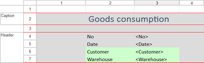
Fig. 545. Displaying spreadsheet document changes
In the spreadsheet document shown in the drawing, cells of the extended spreadsheet document that were not modified in the extension are displayed with a gray background color. Cells that were added in the extension are highlighted with a green background color. For the spreadsheet document cells whose properties have been changed in the extension, the current background color of the spreadsheet document is used.
In the document shown in fig. 545, the following changes can be noted:
-
In rows 11 and 12, cells are added in column 4 (display of the SKU column in the table of the Goods consumption document).
-
In column 6, cells are added in rows 1-4 and rows 9-10. This was a consequence of adding the column with the item.
-
In the cell located in column 2 of row 12, the value of some cell properties is changed, so the cell is displayed with a background color other than gray.
To see the differences in the values of cell properties, there is a special button on the command bar of the cell properties palette.

Fig. 546. Cell property changes
The Show only changed items button is available only in those cells of the adopted spreadsheet document in which the cell properties are changed. When you click this button, the property palette starts displaying only the changed properties. Thus, in the example in fig. 546, you can see that in the cell, which is located in column 2 of row 12, the horizontal alignment is changed. The remaining properties of this cell are unchanged.
Using the Show saved table command, you can see the extended spreadsheet document that marks the areas that are deleted in the spreadsheet document located in the extension. These areas are marked with a red background color. This spreadsheet document is displayed in read-only mode.
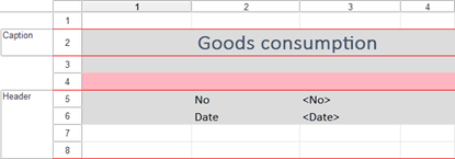
Fig. 547. Deleted cells
It is clear that in the expanded spreadsheet document between the Header and GoodsHeader areas, there were two rows: 9 and 10. However, one row (numbered 10) has been removed in the extension.
The Show result command displays a table (in view-only mode), which is a spreadsheet document that will result from applying the extension that contains the extended spreadsheet document.
The Update table extension command allows you to update an extended spreadsheet document if it is modified in the extended configuration.
30.4.14. Exchange plans
In an extension, you can to manage the controllability of the components of the exchange plan. To do this, set the value check flag when the extension is attached for the Components property of the exchange plan. You can also adopt a specific item of the components of the exchange plan in the extension. In this case, the following is transferred to the extension:
-
Fag of participation of the configuration object in the exchange plan.
-
State of auto-registration of changes.
For an adopted exchange plan, you can add attributes, tables, table attributes, forms, commands, and templates. An adopted exchange plan can include both native extension objects and objects from the extended configuration (which were not previously part of this exchange plan). You cannot exclude extended configuration objects from an exchange plan. In other words, an extension cannot reduce the amount of information passed by the exchange plan.
When attaching an extension, it checks:
-
Match of the flag of participation of the configuration object in the exchange plan.
-
Match of auto-registration of changes.
In an extension, you can create a native exchange plan. Such exchange plan will have the following features:
-
A native extension exchange plan cannot participate in a distributed infobase.
-
The system does not provide tools to automatically synchronize the components of extensions between data exchange nodes. This synchronization must be performed separately.
30.4.15. Catalogs
Catalogs can be both adopted and native. In adopted catalogs, you can add attributes, tables, and table attributes.
30.4.16. Documents and journals
Documents can be either adopted or native. In adopted documents, you can add attributes, tables, and table attributes. For native extension documents, number generators and sequences are not supported.
A document can act as a recorder only for the register that is in the same "part" of the application as the document itself. In other words, a document from an extension can act as a recorder for native and adopted extension registers and cannot act as a recorder for native registers of an extended configuration. And the other way around, a native configuration document cannot be a recorder for a native extension register.
An extension document (both native and adopted) can act as a recorder for any adopted extension register, except for a turnover accumulation register with the aggregate mode enabled.
Document journal creation is supported in the extension. The journal can contain both native extension documents and adopted documents from the extended configuration.
See also:
- Aggregates of turnover accumulation registers (see Turnover accumulation register aggregates).
30.4.17. Enumerations
An enumeration can be adopted or native. It is possible to create new values in an adopted enumeration.
Note the following features:
-
If the infobase uses values from an extending object and the extension is not connected, such values are displayed similarly to references to non-existent objects. The presentation is restored after the extension attachment.
-
When an extension is removed from an infobase, references to enumeration values from the extending object will be cleared and replaced with an empty reference with the extended enumeration type.
-
It might happen that the same references to an enumeration value from different extensions have different meanings. It is possible if you rename a native enumeration value in a copy-created extension. In this case, recording such a value in shared data would lead to a logical issue for the user of the application. For example, an enumeration value with internal ID ID1 will have the Airplane presentation in one extension and the Steamship presentation in another extension. Obviously, it will be difficult for the user to understand what the given enumeration value means. Two features follow from this:
-
It is not recommended that you save native values for adopted enumerations in copy-created extensions. It is recommended that you create all native values manually.
-
It is not recommended that you specify native values of adopted enumerations of extensions which scope is set as "Data separation" in shared data.
-
-
If an attempt is made to install a configuration extension that uses the enumeration value ID equal to the ID of the enumeration value of the extended configuration or another extension, then the infobase cannot be restructured.
-
If the internal ID of the enumeration in the extended configuration is the same as the internal ID of the enumeration of the extension, then:
-
The infobase restructuring is not locked.
-
The extension that contains a conflicting enumeration value is not attached.
-
To restore the functionality of an infobase or area, delete the conflicting enumeration value in the extension and upload a new version to the infobase. Existing references to the enumeration value from the extension will be allowed by the enumeration value from the extended configuration.
30.4.18. Session parameters
Session parameters can be both adopted and native. Native extension session parameters can be used in data access restriction texts.
Initializing and operating native extension session parameters do not differ from initializing and operating extended configuration session parameters.
See also:
- Session parameters (see Session parameters).
30.4.19. Functional options and functional option parameters
Functional options (and functional option parameters) can be either adopted or native. Native functional options supported by the extension can include both native and adopted extension objects.
Functional option values can be stored both in native and adopted extension objects. An adopted functional option can be extended by using both adopted and native extension objects.
See also:
- Functional options and functional option parameters (see Functional options and functional option parameters).
30.4.20. Filter criteria
Filter criteria can be either adopted or native. The extension filter criteria (both native and adopted) can include attributes of native extension objects and adopted configuration objects added in the extension.
See also:
- Filter criteria (see Filter criteria).
30.4.21. Event subscriptions
Subscriptions can be either adopted or native. For native subscriptions, you can specify general types of objects, such as all catalogs or all documents. If you need to create a native subscription to an event of the extended configuration object, adopt this object to the extension.
You can specify both native and adopted extension objects as the event source for adopted subscriptions. Adopted subscriptions only support adding new objects to an event source.
See also:
- Event subscriptions (see Event subscriptions).
30.4.22. Types in adopted objects
Adopted objects allow changing the Type property for the following objects:
-
Constants
-
Session parameters
-
Common attributes that are not separators
-
Attributes and table attributes for the following configuration objects:
-
Exchange plans
-
Catalogs
-
Documents
-
Reports
-
Data processors
-
Charts of characteristic types
-
Charts of accounts
-
Charts of calculation types
-
Business processes
-
Tasks
-
-
Type collections
-
Characteristic type of the chart of characteristic types.
-
Parameter type for common commands and configuration object commands.
-
Accounting flag and extra dimension accounting flags for the chart of accounts.
-
Task addressing attributes
-
Document sequence dimensions
-
Dimensions, resources, and attributes for the following configuration objects:
-
Information registers
-
Accumulation registers
-
Accounting registers
-
Calculation registers
-
Adopted objects do not allow extending the Type property for the following objects:
-
Common attributes that are separators
-
Attributes with types of external data sources
When you extend the Type attribute property, the resulting type is generated so that you can store both extended configuration values and extension values without any losses. In most cases, the resulting type is a union type. This behavior leads to the following distinctive feature: for attributes to be saved to the database, a resulting type cannot contain types that cannot be included in union types (ValueStorage, UUID, and so on).
An attribute type (the Type property) can contain all native and adopted extension types, including type collections, characteristics, and union types such as CatalogRef, DocumentRef, and so on. Union types such as CatalogRef, DocumentRef, and others cannot be included in a type set of a type collection and a chart of characteristic types.
The AllRefsType() method returns a description of types which includes not only the types of the extended configuration, but also all corresponding types of extensions connected at the moment of calling the method.
30.4.23. Type collections
Type collections can be either adopted or native. Type descriptions are changed according to the standard scheme for native and adopted configuration objects.
See also:
- Type collections (see Type collections).
30.4.24. Integration services
Integration services can be either adopted or native. Adopted integration services allow adding new channels and modifying the integration service module.
See also:
- Integration services (see Integration services).
30.4.25. Common attributes
Common attributes can only be adopted extension attributes. You can adopt both a regular common attribute and a common attribute that is a separator.
If an adopted common attribute is not a separator, you can change its types. Changing the structure of separator types is not supported, but it is possible to control the separator type control mode.
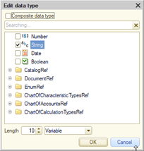
Fig. 548. Separator type control
If the adopted common attribute is a separator, then it is possible to separate the native extension objects with the adopted separator. To do it, add a native extension object to the adopted separator. You cannot specify an automatic method of inclusion in the separator for a native extension object. If a native object is a part of a separator, such extension object will always be separated by the selected separator.
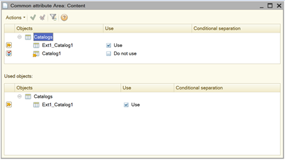
Fig.549 Common attribute components
It is also possible to control whether a particular object of the extended configuration is included (or not included) in the separator. To check whether a main configuration object is a part of the separator:
-
Adopt the separator.
-
Adopt the required object.
-
Set the control method in the Action when a configuration extension is applied column.
-
Specify the state being checked:
-
To check whether an object is a part of a separator, in the Use column, specify Use.
-
To check whether an object is not a part of a separator, in the Use column, specify Do not use.
-
At fig. 549, it is visible that:
-
The Area separator is extended by the Ext1_Catalog1 catalog.
-
To successfully attach the extension, the Area separator must not include the Catalog1 object of the extended configuration.
See also:
- Data separation feature (see Data separation feature).
30.4.26. Configuration object properties
In adopted catalogs, exchange plans, charts of characteristic types, charts of accounts and calculation plans the following is allowed:
- Increase the value of the Code length property. The result will be the maximum value from the connected extensions.
For adopted catalogs and charts of calculation types, it is possible to change the value of the Code type property. If the values of the Code type property in the extended configuration and the extension are different (for the same object), then the String type will be selected as the resulting value of this property. This choice is conditioned by the fact that values of this type can store both numeric and string codes of objects.
- Increase the value of the Description length property. The result will be the maximum value from the connected extensions. This feature is also available for adopted tasks.
For adopted documents, business processes, tasks, and number generators, the following is allowed:
-
Increase the Number length property. The result will be the maximum value from the connected extensions.
-
Define the value of the Number type property. If the values of the Number type property in the extended configuration and the extension are different (for the same object), then the String type will be selected as the resulting value of this property. This choice is conditioned by the fact that values of this type can store both numeric and string numbers of objects.
-
We allow you to set the value of the Number string type, Periodicity and Check for uniqueness properties. The result will be the value from the last connected extension.
When numbering parameters are changed by multiple extensions (or changes in extensions conflict with either the extended configuration or other extensions), the resulting settings are chosen to prevent data loss both when installing the extension and when updating the extended configuration.
In an extension, it is possible to override (extend) the following localizable attributes of configuration objects:
-
Title
-
Format
-
Editing format
-
Tooltip
-
Command tooltip
-
Extended presentation
-
List presentation
-
Extended list presentation
-
Object presentation
-
Extended object presentation
-
Record presentation
-
Extended record presentation
When several extensions that extend the same localizable attribute (from those listed above) are installed, the value obtained from the most recently applied extension will be used.
30.4.27. Templates
Adopted templates can be modified in an extension.
If a template is a spreadsheet document, the application will use the rules for generating resulting spreadsheet documents, see Spreadsheet document. For other types of templates, the template from the most recently applied extension will be used.
30.4.28. Numerators
Number generators can be either adopted or native. Any number generators can be assigned to any documents. When setting a new number generator or modifying an adopted one, the application follows the same collision resolution rules that are applied when changing numbering parameters of the respective object (see Configuration object properties).
30.4.29. Scheduled jobs
Scheduled jobs can be either adopted or native. An adopted scheduled job does not allow modification of its parameters.
If an extension contains a native scheduled job, in the distributed infobase, this job will be executed as follows:
-
For an extension applied with the Data area scope: the scheduled job is executed only in the data area to which the extension is connected, including all extensions connected to this data area.
-
For an extension applied with the Infobase scope: scheduled jobs behave similarly to the scheduled jobs of the extended configuration (see Scheduled jobs). The execution will be performed including all extensions available in this case.
30.4.30. External data sources
External data sources can be adopted or native.
When extending an external data source, the properties of the extended object are completely obtained from the extension (including the Type property). If one external data source is extended by multiple extensions, the property of the object to extend will be defined by the last extension in the list.
See also:
- External data sources (see External data sources).
30.4.31. Business processes and tasks
Business processes and tasks can be native or adopted. Adopted objects can be extended:
-
Business processes: with attributes and object table attributes.
-
Tasks: with addressing attributes, attributes, and object table attributes.
The extension allows you to change a business process route map and tasks that are used to advance the business process. For tasks, you can change properties related to the task addressing. For addressing attributes, you can change the addressing dimension.
All properties that can be changed in the BusinessProcess and Task objects are replaced with values from the extension (including the route map) in the resulting configuration. If one business process or task is changed by several extensions, the property of the object to extend will be defined by the last extension in the list.
In the business process route map editor, you can adopt a separate map item using the corresponding command of the item context menu. The map item is adopted together with outgoing links. Incoming links are adopted together with the items that are the sources of these links. To adopt the entire route map, select all the map items and adopt them. A map item will not be adopted if it already exists in the extension. To update the route map, perform a similar operation. Only those map items that do not yet exist in the route map located in the extension will be transferred to the extension.
When editing a route map in an extension, note that the following route map components can be used from both an extended configuration and an extension:
-
Event handlers of route map items.
-
Addressing attributes.
-
Predefined addressing value items.
See also:
- Business processes and tasks (see Business processes and tasks).
30.5. Extension and distributed infobase
You can use a configuration extension in a distributed infobase. In this case, the extension will be passed between the nodes of the distributed infobase using exchange messages, thereby ensuring a single set of extensions within the distributed system.
To indicate that an exchange plan can pass extensions, select the Enable configuration extensions checkbox for this exchange plan. This checkbox can be selected only for exchange plans that participate in a distributed infobase.
At the same time, each extension connected to the infobase has the Used in distributed infobase property. Setting this property means that the extension will migrate to subordinate infobases. The option to change this property is not related to the actual presence in the infobase of exchange plans included in the distributed infobase.
The ConfigurationExtension object has the MasterNode property, which allows you to determine that the extension was added to the current node (the property has the Undefined value) or received using the data exchange feature (contains a link to the master node of the distributed infobase).
Creating the initial image and exchange message
When you create an initial image of a peripheral infobase that supports passing configuration extensions, all extensions that are attached with the Shows whether the extension is used in a distributed infobase checkbox selected are passed to it. Creating the initial image will not be possible if in the session from which the initial image is being created:
-
There are unattached extensions with the Shows whether the extension is used in a distributed infobase checkbox.
-
There are extensions that change data for which the Shows whether the extension is used in a distributed infobase checkbox is selected and which are not active.
-
There are extensions that change data for which the Shows whether the extension is used in a distributed infobase checkbox is not selected.
-
There are extensions with the Shows whether the extension is used in a distributed infobase checkbox for which new extension versions are loaded.
At the time of generation of the exchange message, the same requirements are imposed on the session from which the generation is performed as in the generation of the initial image.
Managing extensions
In the peripheral node of the distributed infobase, you cannot edit the properties of extensions and delete extensions that are added to the master node. These actions are prohibited both interactively and using the methods of 1C:Enterprise language. A flag that the extension is received using the data exchange feature is displayed in the interface of the standard Configuration extensions management function.
When starting a session, extensions are applied in the following order:
-
Extensions added by the master node in the same order in which they are applied in the master node.
-
Extensions added to the current node in their order.
If a distributed infobase node receives a message that the Shows whether the extension is used in a distributed infobase checkbox for the extension is cleared, then such extension is deleted.
If an infobase has extensions that were received using distributed infobase exchange messages, then in such infobase, using the MasterNode() method of the exchange plan manager, there you can install only that node from which the extensions were received or disable the infobase from the distributed system (set the Undefined value). In particular, this means that without removing extensions, you cannot switch an infobase from one distributed infobase to another by changing the master node.
See also:
-
Distributed infobase (see Distributed infobases).
-
Initial image of a distributed infobase node (see Initial image of a distributed infobase node).
-
Data exchange message (see Data exchange message in a distributed infobase).
30.6. Security profiles
When you attach an extension to an application, you can specify whether the extension will run in safe mode or not. To do this:
-
Explicitly indicate the Safe mode checkbox. In this case, the extension will run in safe mode (see Safe mode) or unsafe mode (depending on the checkbox state).
-
By specifying the name of the security profile under which the extension will be executed. This feature is only available if the application is used in a client/server mode.
Specifying a security profile upon connection indicates that the operation mode of the extension is determined by the settings of the specified security profile. In the security profile, specify access to the extension in the settings of the External modules item.
If the security profile does not allow unsafe use of external modules, and the extension requires such use, then you can add the extension to the list of exceptions. To get the checksum value of the extension to be added to the list of exceptions, use the dialog boxes for extensions or the API for operation with the extensions. Enter the resulting checksum value into the appropriate field in the cluster administration console.
When attaching an extension, it checks whether it is possible to enable unsafe mode (if required). If the current extension does not meet the requirements of the specified security profile, the extension is not attached and an error is generated.
To change the safe mode settings when connecting an extension, the user performing these settings must have the Administration right (in addition to the ConfigurationExtensionsAdministration right, which allows performing other actions with extensions).
30.7. Attaching extensions and time of their operation
30.7.1. General information
An extension is attached to a user session before calling the SessionParametersSetting event handler and remains attached until the session ends. Updating an extension (using administration tools) does not update the extension in existing sessions. Existing sessions will continue to run with the "version" of the extension that was available when the session started. In order for the user session to start managing the new "version" of the extension, restart the session.
If the configuration extension uses a data extension, then the creation of new tables (for storing the extension data) in the infobase is performed:
-
In Designer, when restructuring the infobase.
-
In 1C Enterprise mode, when adding or updating an extension. The change in the database structure is performed during the execution of the Write() method of the ConfigurationExtension object.
When deleting an extension, the procedure is the same, but instead of creating tables, they are deleted.
The order of attaching extensions depends on the purpose of the extension and its scope. Extensions are attached in the following order:
-
Patch
-
Customization
-
Add-on
Within each purpose, extensions with the Infobase scope are attached first, and then extensions with the Data area scope are attached. If there are several extensions with the same purpose and scope, the order of attaching such extensions is generally not defined.
When attempting to connect extensions, each extension is sequentially checked for compliance of the controlled attributes between the extension and the configuration of the infobase. If at least one controlled attribute does not pass the check, an error message is displayed to the user, and this extension is not connected. When checking properties with multiple values (union type, common attribute components), the value from the extension is controlled for occurrence. All values that are in the extension must be in the extended configuration. However, some components of the extended configuration may not be a part of the controlled property. As a result, all extension objects stop participating in the formation of the resulting configuration.
If problems are detected while connecting extensions, a dialog box appears informing the user about which extensions caused issues. A detailed issue list is accessible via the Information for technical support hyperlink available in this dialog box.
In addition to interactive check, the 1C:Enterprise platform provides the ability to perform the check from 1C:Enterprise language code. You can perform a check for a specific extension using the ConfigurationExtension.CheckCanApply() method. You can also check all extensions that are currently attached. To do this, use the ConfigurationExtensions.CheckCanApplyAll() method.
30.7.2. Operations at mismatch of data structures in configuration and infobase
If not all extensions that extend data are attached at the session start, the application can read the extended configuration data of successfully attached extensions without errors. When attempting to write an object whose data is supplemented with a disabled extension, the behavior depends on the used object:
Catalogs, documents, and exchange plans
You can create new objects, delete existing objects, and record changes in existing objects. When you create objects, disabled extension fields are filled with default values. Field values from disabled extensions are saved to objects to be modified. When you copy an object, field values from disabled extensions are not copied to a new object.
Tables
When you edit table rows (programmatically or interactively) and change the row order, data is saved to disabled extension fields. When you create rows, disabled extension fields are filled with default values. When you copy rows, field values from disabled extensions are not copied to a new row.Registers
Registers for which the list of recorders is extended with an inactive extension support writing a record set only for recorders provided by the extended configuration. Reading is supported for any record set. However, in such record set, a recorder provided by an inactive extension is presented by the Undefined value. As a result, you cannot change or delete such record set.Attribute types
When a type of an application attribute (dimension, resource, and so on) is modified with a disabled extension:-
When reading an object with this attribute, values stored in the infobase are converted to configuration types ignoring inactive extensions. Values are converted according to the TypeDescription.AdjustValue() method. References to inactive extension objects are pre-converted to the Undefined values.
-
When writing an object with this attribute, only changed values are updated (programmatically or interactively). Infobase fields that are not changed in an object to be written can save values that are set for active configuration extensions. A value to be written is adjusted to configuration types ignoring inactive extensions.
-
When copying an object with such attributes: values of attributes modified by an inactive extension are copied to the new object with their values converted to match the type of the extended configuration without considering inactive extensions.
-
While executing a query, values stored in the infobase are used in expressions, filter conditions, groupings, and upon ordering.
When specifying an object in conditions and groupings, links to objects from inactive extensions are considered filled. When used in conditions, these references are not compared to the Undefined and NULL values. In other cases, these references are converted to Undefined.
A call to attributes of references (dot-separated) to objects from inactive extensions returns NULL.
When reading the query result into 1C:Enterprise language objects, values are converted to configuration types ignoring inactive extensions.
Behavior specifics
When the user starts a session in an area with a data extension and then switches to a data area with other extensions or updates/adds an extension that changes the infobase structure, they still cannot read or write tables modified in the initial area.
See also:
-
General extension information (see General information).
-
Separating configuration extensions (see Configuration extension separation).
-
Separators and configuration extension (see Configuration extension).
30.8. Operating with extensions from 1C:Enterprise language
If you need to implement native extension tools, use a specialized API. Its methods are available if the current user has the ConfigurationExtensionsAdministration right. The current session must run in unsafe mode if the Write() method of the ConfigurationExtension object is used.
The API is provided through the configuration extension manager, which is represented by the ConfigurationExtensions global context property. Detailed description of the methods is provided in the Syntax Assistant.
There are two methods to connect the extension:
Method 1
Ext1 = ConfigurationExtensions.Create()
Ext1.Write(New BinaryData(ExtensionFilePath))In this case, the extension is recorded into the infobase.
Method 2
Ext1
= ConfigurationExtensions.Create(New BinaryData(ExtensionFilePath));In this case, the extension is not written to the infobase until the Write() method is used. This method can be used when it is necessary to perform some checks before writing the extension to the infobase, for example, to check that the extension does not change the data structure.
Such a check will look like the following:
Ext1 = ConfigurationExtensions.Create(New BinaryData(ExtensionFilePath));
If Ext1.ModifiesDataStructure() Then
// the extension changes the
data structure
Raise "Cannot apply
such extension";
Else
// the extension does not
change the data structure
Ext1.Write();
EndIf;To check if extensions have been changed during the current session, use the ConfigurationExtensionsChanged() method. This method is similar to the ConfigurationChanged() method, which allows you to check that the main configuration differs from the infobase configuration.
Using the 1C:Enterprise language, you can check whether a configuration object is extended in the current session. To do this, use the <Metadata object>.ChangedByConfigurationExtensions() configuration object method. This method will return the True value if in the current session the selected configuration object is modified by extensions in one of the following ways:
-
Configuration object property is modified.
-
Added a new child object of the configuration object (form, template, command, etc.).
-
A property of one of the child objects is modified.
Using the <Metadata object >.ConfigurationExtension() method, you can determine which configuration or extended configuration extension the configuration object belongs to.
Chapter 31. Debugging and testing applications
31.1. General information
Debugging is a phase in the application development process. It involves finding, localizing, and eliminating application errors.
Debugging can include using a Debugger (see Debugger), performance measurement results, mapping server calls (see Server call history), and simulating delays when calling the server (see Server call delay simulation). You can also run the automated testing scenario (see Automated testing of applications). In this case, testing refers to the process of testing the software designed to identify situations where the application behavior does not comply with the specifications.
This chapter describes platform tools that can be used for application debugging and testing.
31.2. Debugger
31.2.1. General information
Debugger is a tool you can use to easily develop and debug modules in 1C:Enterprise. With Debugger, you can do the following:
-
Debug module execution in both file mode and client/server modes and background jobs.
-
Execute modules step-by-step (see Step-by-step execution).
-
Set breakpoints (see Breakpoint).
-
Interrupt and resume module execution.
-
Debug multiple modules at the same time.
-
Calculate expressions for variable status analysis (see "Expression" window).
-
Change variable values during the debugging process (see Variable value change).
-
View the call stack of procedures and functions (see Call stack).
-
Interrupt upon errors.
-
Edit the module during the debugging process.
You can debug using two protocols: over TCP/IP and HTTP. The capabilities provided by both debug protocols are fairly close. The following text applies equally to both protocols, unless any particular features or limitations explicitly specified.
The Debugger involves a debug item. Debug item is the context of 1C:Enterprise language with the following parameters:
-
User name to run the code in 1C:Enterprise language.
-
Debug item type.
-
Session number used.
-
Network name of the computer, on which the code in 1C:Enterprise language is executed (for the TCP/IP debug protocol).
-
IP port number, through which the Debugger controls the debug item (for the TCP/IP debug protocol).
-
Infobase name (for the HTTP debug protocol).
Note. Note. If there are several workflows in the cluster in the client/server mode, and the session was reassigned to another workflow while debugging the code of the web client or server, debugging becomes impossible.
Types of debug items include:
-
COM connection. 1C:Enterprise language code executed through an external connection.
-
HTTP service. 1C:Enterprise language code executed when calling HTTP service methods.
-
WebSocket. 1C:Enterprise language code executed when calling WebSocket client event handlers.
-
Web service. 1C:Enterprise language code executed when calling web service methods.
-
Standalone server (standalone mobile client)*. 1C:Enterprise language code executed on a mobile device, on the standalone server of the mobile client.
-
Web client. 1C:Enterprise language code executed in the web client.
-
Client (mobile application)*. 1C:Enterprise language code executed in the client application on a mobile device.
-
Mobile client*. 1C:Enterprise language code executed in the mobile client.
-
Server (mobile application)*. 1C:Enterprise language code executed on a mobile device, in the application on the mobile platform, on the server, or in file mode.
-
Server (file mode). 1C:Enterprise language code executed on the server in file mode.
-
Server. 1C:Enterprise language code executed on the server.
-
Standard OData interface. 1C:Enterprise language code executed when you access an infobase via the standard OData interface.
-
Thick client. 1C:Enterprise language code executed in the thick client.
-
Thin client. 1C:Enterprise language code executed in the thin client.
-
Background job (mobile application)*. 1C:Enterprise language code executed in a background job (in file mode) on a mobile device.
-
Background job (file mode). 1C:Enterprise language code executed in a background job (in file mode).
-
Background job. 1C:Enterprise language code executed in a background job.
Debug items marked with an asterisk "*" are used only if the HTTP debug protocol is applied.
During debugging, to indicate the system component addresses, both symbolic addresses (for example, pc-name) and IP addresses (for example, 192.168.1.1) can be used. 1C:Enterprise subsystems convert symbolic names to IP addresses, for example, to get the Debugger IP address, which is specified using a symbolic name. For this purpose, specialized services of the operating systems (DNS) are used. It is desirable that there are no ambiguities while resolving symbolic names.
Depending on the debug protocol used, 1C:Enterprise organizes the system components interactions in different ways. No matter what protocol is used, some ports of the protocol underlying the Debugger operations are used. If necessary for debugging ports are not allowed on the computer (the ports are "closed"), then debugging is unavailable. The following might happen:
-
Longer startup time of the client application.
-
1C:Enterprise server workflow (rphost) slows down if the server is running in debug mode (debug key).
The following ports are used when running the Debugger:
-
When you use the TCP/IP debug protocol: 1560-1591 (default). The range of ports can be changed. Ports are used on both Debugger side and the debug item side.
-
When you use the HTTP debug protocol: the debug server port that is explicitly specified at startup. When working in the client/server mode, the debug server uses port 1550 (by default). When working in the file mode, the port is assigned explicitly or selected by the Designer from the port range 1560-1591 (by default). The range of ports can be changed. The port is used only on the computer where the debug server is running.
When using the TCP/ IP debug protocol, the port range can be changed using the system component settings or configuration files (debugcfg.xml). Ports used (single or range) must be enabled for use ("open") on computers that are involved in the debugging process. For the TCP/IP debug protocol, these are all the computers involved in debugging, and for the HTTP debug protocol, this is the debug server computer.
31.2.2. Using Debugger
31.2.2.1. TCP/IP debug protocol
31.2.2.1.1. How it works
To debug 1C:Enterprise language code, run the application that executes the code in the debug mode. Debug mode requires the TCP/IP network protocol support enabled on the computer.
If 1C:Enterprise is not launched, select Debug – Start Debugging to start debugging. Designer launches the client application in debug mode.
If debug mode is enabled or debugging is set to begin upon startup in the Designer settings. You can open them by selecting Tools – Options –1C:Enterprise startup tab. You can also launch debugging in the run mode by selecting Tools – 1C:Enterprise. If you want to debug the code executed by a specific user, then in the settings form you can specify the user under which the debug mode is started.
The Debugger and debug items use IP address 127.0.0.1 when searching for each other. To ensure stable operation of the data transport service, it is necessary to determine the correspondence of the address 127.0.0.1 to symbolic name localhost. For this purpose, write the following mapping to the file C:/Windows/system32/drivers/etc/hosts
127.0.0.1
localhost31.2.2.1.2. Application setup in debug mode
General information
In this section, it is assumed that the Designer is configured for debugging using the TCP/ IP debug protocol. You can set up Designer in the Designer settings dialog box (see Debugging). Later we do not remind to set it up.
Debugging client applications
To set the debug mode, you can use the following startup options:
-
In the Designer mode, in the settings form (Tools – Options) on 1C:Enterprise startup – Additional tab, select the Enable debugging mode checkbox and then attach the debug item. You can also select Begin debugging on startup. In this case, connection is established automatically at 1C:Enterprise startup. In this case, the TCP/IP protocol must be used for debugging (the Tools – Settings dialog box, the Debug tab, Debug protocol property must be set to TCP/IP debugging).
-
Open the infobase in 1C:Enterprise mode with the /debug –tcp command-line option (debug mode).
-
If the client application is running, set debug mode in the settings form (open via the Tools – Options menu). For this purpose, the Debug in the current session property should be set to Enabled (TCP/IP protocol). Note that you cannot change this property value after you have applied these settings.
Debugging server code (including standalone server)
standalone server)In the debug mode, the configuration objects are loaded as needed, and not at the system startup as in the normal server operation mode. This speeds up the startup process of 1C:Enterprise when changing the configuration, so it accelerates the development process.
You should also keep in mind that the system performance is lower in the debugging mode than in the normal mode. So, it is not recommended to use the debug mode of the server for real user operations.
Server as an application
If the 1C:Enterprise server runs in an application mode (in any OS), you should stop the server and restart it to include the -debug parameter in the command line settings.
ragent
/debug <other command line settings>Server as a Windows service
If the server runs as a Windows service, you need to do the following:
- Stop the 1C:Enterprise server.
ragent
/stop- Re-register a server agent as the Windows service to include the -debug parameter to the list of ragent command settings.
ragent
/instsrvc /debug <other command line settings>- Start the 1C:Enterprise server.
ragent
/startServer as a Linux service
To transfer the 1C:Enterprise server working as a Linux service into debug mode:
- Stop the 1C:Enterprise server.
systemctl stop
srvc1v8-A.B.C.D@instanceName- In the srvc1v8-A.B.C.D@instanceName configuration service file, set the value of the SRV1CV8_DEBUG parameter to -debug.
SRV1CV8_DEBUG=-debug-
Save the configuration file.
-
Start the 1C:Enterprise server.
systemctl start
srvc1v8-A.B.C.D@instanceNameThe command line examples above in this section use the following notations:
-
A.B.C.D is a full number of the installed 1C:Enterprise version.
-
instanceName. Name of a 1C:Enterprise service instance.
Standalone server
To enable debug mode in a standalone server, use the --debug command or the debug section of the standalone server configuration file. If the standalone server is running without debug mode, stop the standalone server, change the startup command line (or configuration file), and start the standalone server again.
ibsrv <current command line
options> --debug=tcpTo manage debugging in the standalone server configuration file, use the debug section of the following kind:
debug:
type: tcpSee also:
-
Running server agent on Linux.
-
Running server agent on Windows.
-
Debugging in the standalone server.
-
Server cluster configuration file on Linux.
-
Standalone server configuration file.
Debugging external connection
To enable debug mode for an external connection, use the settings located in xml file comcntrcfg.xml, which is located in the 1C:Enterprise system configuration files directory. If the file cannot be found, the application runs in the standard mode.
Sample of comcntrcfg.xml file:
<config
xmlns="http://v8.1c.ru/v8/comcntrcfg">
<debugconfig
debug="true" protocol="tcp"
debuggerURL="tcp://localhost:1560"/>
</config>If the debuggerURL attribute is set for the debug item, then Designer should be available at the specified URL when accessing the external connection. Otherwise, the external connection will be suspended and the system will wait for the Designer availability. At the same time, to continue working in the Designer mode, you should attach the required debug item.
Debugging web service, HTTP service, and access via the standard OData interface
To indicate that the service needs to be started in debug mode (only for the file mode of the infobase), use the settings that are located in the default.vrd file, which should be located in the virtual application directory. You need to specify the debug item in this file. If you don't do it, the Web service cannot be debugged.
Sample of the debug item from default.vrd file:
<debug
enable="true" protocol="tcp"
url="tcp://localhost"/>If the url attribute is set for the debug item, then Designer should be available at the specified URL when accessing the service. Otherwise, the service will be suspended and the system will wait for the Designer availability. At the same time, to continue working in the Designer mode, you should attach the required debug item.
To debug a service in the client/server infobase, enable debug mode on the server using the debug command-line option.
Note. Note. To debug an HTTP service and to operate with standard OData interface, it is not recommended to use the Microsoft Internet Explorer 9.0 web browser, because there are URL coding errors in this web browser.
Debugging web client
To set the debug mode, you can use the following startup options:
-
In the Designer mode, in the settings form (menu Tools – Options) on 1C:Enterprise startup – Additional tab, select the Enable debugging mode checkbox and then attach the debug item. You can also select the Begin debugging on startup checkbox. In this case, connection will be established automatically at 1C:Enterprise startup.
-
Open the infobase in the 1C:Enterprise mode by using the debug command-line option (debug mode):
[http://localhost/demo?debug](http://localhost/demo?debug)=tcp- Open the infobase in the 1C:Enterprise mode by using the debug command-line options debug and debuggerurl="IP-address":
[http://localhost/demo?debug](http://localhost/demo?debug)=tcp&debuggerurl="127.0.0.1"- IP address is the debugger address. If the Debugger located at 127.0.0.1 is launched, it will automatically attach the debug items (the Debugger must be run at the specified address).
To enable the debugging of the server file mode of the infobase, you can use two methods:
-
Start debugging directly from the Designer as described above. In this case, debugging of the server file mode on the computer with the web client starts automatically.
-
Enable debug mode using default.vrd file. It should be located in the virtual application directory. You need to specify the debug item in this file. If you don't do it, the Web service cannot be debugged.
Sample of the debug item from default.vrd file:
<debug
enable="true" protocol="tcp"
url="tcp://192.168.0.30"/>You should also keep in mind that the system performance is lower in the debugging mode than in the normal mode. So it is not recommended to use the debugging mode of the server file mode for real user operations.
When debugging a web client, you need to remember the following:
-
You cannot interactively enable the debugging mode.
-
Automatic search of debugging objects on remote computers is not supported when debugging a web client for the file mode infobase.
-
Designer activation from the web client is not supported during debugging.
-
Debugging external reports and data processors is not supported.
-
In case of forced termination of the web client from the Debugger, the process of the web browser that started when the web client was started from Designer is terminated. However, if the web client starts in the tab of an already running web browser, then the forced closing of the tab does not occur and a dialog box opens in the debug web client window with information indicating that the web client is terminated at the request of debugger.
Note. Note. To debug a web client (including client program code) in the client/server mode, the 1C:Enterprise server should be launched in the debug mode (debug key).
Note. Note. It is not recommended that you use web client debug in low-speed communication channels.
Debugging external data processor (report)
To debug an external report (data processor), the following conditions must be met:
-
External data processor (report) is opened in the client application from a specific file mode location.
-
Designer, which serves the debug item with debugged external data processor (report), has access to the external data processor (report) file that is opened by the client application.
If these conditions are not met, debugging the external data processor (report) will be impossible. In particular, debugging of external data processors (reports) located in the infobase are not supported. In this case, it is recommended to extract the external data processor (report) from the infobase for the time of debugging.
31.2.2.1.3. Attaching debug items
To debug a module, the debug item should be attached. To manage an attachment, select Debug – Attachment. The debug item selection dialog will be displayed. The list includes only those debug items, for which the following conditions are met:
-
Debugger and the debug item have the same infobase ID:
-
For the file mode of infobase, it is generated at the first access to the database using the client application (including the Designer access). At the next first access the ID will be re-generated. The "first access" is not an absolute first access at the moment of creating the infobase, but the first call after the infobase has no more connections left.
-
For the infobase in the client/server mode, the infobase ID in 1C:Enterprise server cluster is used.
-
-
The application must have the debug option enabled (for the server – the debug checkbox, for the client application – the corresponding command line parameter, or the property of the client application settings dialog box, or a correctly configured configuration file).
Debug items can be attached throughout the time interval of the session, within which a specific background job, Web service, or external connection is running. This interval can be very short, and in this case you can configure the debug items automatic connection.
Note. Note. When a debug item is attached, the infobase users list should include users, which can be authenticated both in the Designer and in the debug item.
Usually the list contains one line that refers to the configuration running in the 1C:Enterprise mode. If several 1C:Enterprise applications are running with this configuration, the list may contain several lines.
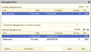
Fig. 550. Attaching debug items
If the Search for debug items on remote computer checkbox is selected, enter a computer name or a network address in the box to the right of the checkbox or select it from the list of previously entered names. The debug items found on the remote computer will be added to the available debug items list. The list of attached debug items contains the items already attached to the Debugger.
When you click Attach, the selected debug item is attached to the Debugger. In the attachment window, this is displayed by the transfer of the debug item from the list of available debug items to the list of attached debug items.
To exclude a debug item, you need to specify it in the list of attached items and click Detach. For a detached debug item, debugging is no longer performed. In particular, this means that the breakpoints set in detached debug items do not function during walkthrough of them. In the attachment window, this is displayed by moving the debug item from the list of attached items to the list of available items. You can re-attach to it.
To close the debug item, click Finish. To stop at the execution point, click Stop.
To open a range setup dialog box, click Options. Specify the port range to search for debug items. The search is performed on the current computer or on the specified computer.
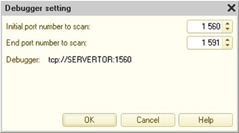
Fig. 551. Setting up Debugger
The Debugger field of the dialog box contains the current Debugger settings. You can use them, for example, in a command line during the client application startup as the /debuggerurl command-line option parameter or in an XML file containing debug settings for external connection or Web service.
To set auto-attachment for debug items on the 1C:Enterprise server running in the debug mode, use the Automatic attachment dialog box and select the required debug item types.
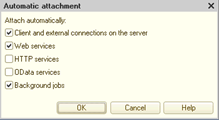
Fig. 552. Auto-connection settings
The specified settings for automatic connection are valid only for the client/server infobase, except for Background jobs, which can be used to automatically connect background jobs, both in the client/server and in the file modes of infobase. If it is necessary to debug various services (WEB-, HTTP– and OData-) in the file mode of infobase, then debugging should be configured in the publishing dialog box on the web server.
Auto-connection of a background job run by the client application or a web server extension is indirectly managed in this dialog box. Background jobs can only be debugged if certain conditions are met:
-
For thin or thick client:
-
Allow debugging in the client application.
-
Allow auto-connection to background jobs in the auto-connection settings dialog box.
-
-
For web server:
-
Allow debugging for the infobase in the publication file (default.vrd).
-
Allow auto-connection to background jobs in the auto-connection settings dialog box.
-
31.2.2.1.4. Additional port range settings
If all ports for connection within the standard range are occupied, you can specify additional range. This range can be specified in debugcfg.xml file located in the configuration files directory, on the computer where the Designer and debugged client application are located, or where an external connection is established. If a port range is changed on the computer with the debugged application, these ports should be set for the Designer where debugging takes place (if the debugged application and the Designer are located on different computers). If the file is not found, then ports from the standard range (1560-1591) are used for communication. Debug items on the server use the same ports as the server processes: rmngr and rphost. Additional port ranges for debug items on the server are not required.
Example:
<config
xmlns="http://v8.1c.ru/v8/debugcfg">
<debugports range="1540:1550"/>
</config>31.2.2.2. HTTP debug protocol
31.2.2.2.1. How it works
To debug 1C:Enterprise language code, run the application that executes the code in the debug mode. Debug mode requires TCP/IP network protocol support enabled on the computer and HTTP protocol operation is not blocked (various proxy servers, firewalls, and other).
When using the HTTP debug protocol, a special debug server (dbgs) is used for debugging. Debug server acts as the debugging process coordinator:
-
Stores lists of debug items available for use and lists of attached debug items.
-
Translates debug control commands to debug item commands (stop, continue execution, and other).
-
Stores a list of users who can debug. It also stores the user rights to perform some actions during debugging.
The general debugging procedure using a debug server can be represented as follows:
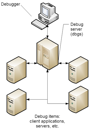
Fig. 553. General operation procedure
There is no direct information transfer between the Debugger and debug items. All interaction is organized through the debug server. A message queue is organized on the debug server, through which the debugger and debug items transmit information to each other.
Both the debugger and debug items interact with the debug server using the HTTP protocol. It does not matter where the debug item is located.
Interaction with the debug server is initiated by the debugger and debug items. During operation, two connections are established between the debug server and each process party (debug items and debugger). One connection is used by the debug item to report its status to debug server (a breakpoint is reached, step is completed, and other). Another connection is used by the debug item or debugger to find out whether the information appears for it on the debug server. And if it is there, to receive this information.
Thus, there is a one-way interaction. Information is transmitted all the time from the debug server to the debugger and to the debug items. It should be understood that if the debug item is not running in debug mode, the debug server will not be able to establish a connection with it. In particular, this means that it is impossible to debug the code on the 1C:Enterprise server if the server is not running in debug mode.
The debug server can handle debugging of an arbitrary number of debug items from different infobases. Debugger and debug items on the debug server are compared on the basis of the infobase name. These names are different and depend on the use case of the infobase:
-
Client/server mode. The infobase name is used as defined in the 1C:Enterprise server cluster.
-
File mode. Predefined name DefAlias is used, you cannot change it. So, in case of a file infobase, the debug server should be used for concurrent work only with the debugger and debug items from one file infobase. Upon the file infobase Designer startup, the debug server for the used infobase automatically starts, too. When you start the client application from the Designer, it is passed the address of the debug server running for this infobase. Thus, when two Designers work with two file infobases, two debug servers will be used, each for its own infobase. At the same time, when launching a client application not from the Designer, you must manually specify the correct debug server address in the command line of the client application (if debugging is needed).
In Designer, you can customize the infobase name used by the Debugger to register on the debug server (see Debugging). This feature is used in cases when one infobase is open in the Designer, but debugging is required for debug items from another server infobase with a known name on a known debug server.
Let us consider what happens when a breakpoint is encountered when using a debug server. After the debug server received a message stating that a particular debug item stopped at a breakpoint, it sends a message stating that all connected debug items should stop. Each debug item executes this command before starting the execution of the next "own" code line in 1C:Enterprise language. Attached debug items stop asynchronously. The debug items of the current session (these are the client application and the server servicing this client application) stop synchronously, and it is generally impossible to determine when other debug items stop. After the command is executed in the debugger, for example, take a step, the debug server informs all attached debug items that they can continue to perform their work. At the same time, the specified command is executed in the active debug item, and the "take a step" operation can be represented (with some approximation) as launching the debug item with setting a breakpoint on the next line. Once the active debug item has completed the requested operation, it reports this to the debug server and the process repeats.
Two important facts follow from this description:
-
It is impossible to simultaneously debug various debug items related to the same infobase (client/server mode) or the same debug server (file mode).
-
With a single step in the current debug item, it is impossible to predict (in general case) where the stop will occur in the other attached debug items. As part of this statement, it could be considered that the client and server debug items related to the same session number act as one debug item.
You can specify users who can use the debug server and infobases that can be used for debugging. You can do this when the debug server is used as an external debug server for remote infobases. In this case, a configuration file with the following information is passed to the debug server via the command-line parameters:
-
List of infobases where debugging is possible.
-
List of users (for each infobase) who can connect to the debug server.
-
Permissions of each user. That is, what a user can do during application debugging.
When a new user is connected, the debug server requires the user to specify a username and password as specified in the list of users from the configuration file. Designer executes this query when connecting to the debug server. If the user is authorized in the debug server, they can debug within the permissions specified in the configuration file. Other debug server operations are unchanged.
31.2.2.2.2. Application setup in debug mode
General information
In this section, it is assumed that the Designer is configured for debugging using the TCP/ IP debug protocol. You can set up Designer in the Designer settings dialog box (see Debugging). Later we do not remind to set it up.
Debugging when starting from Designer
In order for the client application to start up from the Designer immediately in debug mode, start the client application by clicking Debug – Start debugging. In this case, the client application will be launched in debug mode, and all necessary components will also be launched with the correct settings or command line settings. This will start the client application that is selected in the Designer settings (see General parameters).
To start a specific application in debug mode without changing the default settings, you can start it by clicking Debug – Start debugging. The menu lists client applications that can be launched in debug mode.
Starting a mobile application debug from Designer is supported only for devices running Android OS. In this case, the device must be attached to the personal computer that is running Designer using a USB cable and in the start settings of the mobile application (see Mobile application), Android Debug Bridge to start the mobile application must be configured. Debugging a mobile application on an iOS device is only possible when the application is launched manually on the mobile device. For more information about debug management on a mobile device, see Debugging mobile application.
Enable debugging in a running client application
In case you need to debug an already running client application without debug mode enabled, you should perform the following steps:
-
Go to Service and settings – Settings and click Parameters. The dialog box to set up the client application parameters opens.
-
Set the Debug in current session property to Debug in current session.
-
In the Debug server property, specify the address of the debug server being used.
-
Click OK. After you enable debugging in the current session, you cannot disable it or change the debug protocol.
Enable debugging in a running client application is not supported when using a web client.
Debugging server code (including standalone server)
In the debug mode, the configuration objects are loaded as needed, and not at the system startup as in the normal server operation mode. This speeds up the startup process of 1C:Enterprise when changing the configuration, so it accelerates the development process.
You should also keep in mind that the system performance is lower in the debugging mode than in the normal mode. So, it is not recommended to use the debug mode of the server for real user operations.
Server as an application
If the 1C:Enterprise server runs in an application mode (in any OS), you should stop the server and restart it to include the -debug parameter in the command line settings.
ragent / debug –http <other command line
settings>If necessary, you should also specify the values of the /debugServerAddr,/debugServerPort, and /debugServerPwd parameters in the server startup command line.
Server as a Windows service
If the server runs as a Windows service, you need to do the following:
- Stop the 1C:Enterprise server.
ragent /stop- Re-register a server agent as the Windows service to include the -debug parameter to the list of ragent command settings.
ragent /instsrvc /debug http <other command line
settings>If necessary, you should also specify the values of the /debugServerAddr, /debugServerPort, and /debugServerPwd parameters in the server registration command line.
- Start the 1C:Enterprise server.
ragent /startServer as a Linux service
To transfer the 1C:Enterprise server working as a Linux service into debug mode:
- Stop the 1C:Enterprise server.
systemctl stop
srvc1v8-A.B.C.D@instanceName- In the srvc1v8-A.B.C.D@instanceName configuration service file, set the value of the SRV1CV8_DEBUG parameter to -debug -http.
SRV1CV8_DEBUG=-debug
-http-
Save the configuration file.
-
Start the 1C:Enterprise server.
systemctl start
srvc1v8-A.B.C.D@instanceNameThe command line examples above in this section use the following notations:
-
A.B.C.D is a full number of the installed 1C:Enterprise version.
-
instanceName. Name of a 1C:Enterprise service instance.
Standalone server
To enable debug mode in a standalone server, use the --debug command or the debug section of the standalone server configuration file.
ibsrv <current
command line options> --debug=httpTo manage debugging in the standalone server configuration file, use the debug section of the following kind:
debug:
type: httpWith these settings, the standalone server debug server will use the default network port (1550). To change the value, use either the --debug-port command or the port parameter of the debug section of the configuration file.
See also:
-
Running server agent on Linux.
-
Running server agent on Windows.
-
Debugging in the standalone server.
-
Server cluster configuration file on Linux.
-
Standalone server configuration file.
Debugging external connection
To enable debug mode for an external connection, use the settings located in xml file comcntrcfg.xml, which is located in the 1C:Enterprise system configuration files directory. If the file cannot be found, the application runs in the standard mode.
Sample of comcntrcfg.xml file:
<config
xmlns="http://v8.1c.ru/v8/comcntrcfg">
<debugconfig
debug="true" protocol="http" debuggerURL="http://pc
name:1561"/>
</config>If the debuggerURL attribute is specified for the debug item, then the debug server should be available at the specified address when the external connection is used. Otherwise, the external connection will work in ordinary mode and it will not be possible to debug it.
Debugging web service, HTTP service and access via the standard OData interface
OData interfaceTo indicate that the service needs to be started in debug mode (only for the file mode of the infobase), use the settings that are located in the default.vrd file, which should be located in the virtual application directory. You need to specify the debug item in this file. If you don't do it, the Web service cannot be debugged.
Sample of the debug item from default.vrd file:
<debug enable="true"
protocol="http" url="http://pc name:1561"/>If the debuggerURL attribute is specified for the debug item, then the debug server should be available at the specified address when using the service. If at the moment of launching the application, the debug server will be unavailable, debugging will be impossible, and the platform will work as usual.
To debug a service in the client/server infobase, enable debug mode on the server using the /debug command-line option.
Note. Note. To debug an HTTP service and to operate with standard OData interface, it is not recommended that you use the Microsoft Internet Explorer 9.0 web browser, because there are URL coding errors in this web browser.
Debugging web client
If the web client is started not from Designer, then to debug the client, the following actions should be performed:
-
Determine the address of the debug server with which the debugger will interact. To find out how to do it, see Getting the debugger address.
-
Open the infobase in 1C:Enterprise mode, indicating the need for debugging:
[http://localhost/demo?debug=http,attach&debuggerURL="addr](http://localhost/demo?debug=http,attach&debuggerURL=%22addr)"addr value is acquired on the previous step.
- In this case, the debugging of the server application code will be unavailable.
To enable the debugging of the server file mode of the infobase, you can use two methods:
-
Start debugging right from Designer (see Debugging when starting from Designer).
-
Enable debug mode using default.vrd file. It should be located in the virtual application directory. You need to specify the debug item in this file. If you don't do it, the Web service cannot be debugged.
Sample of the debug item from default.vrd file:
<debug enable="true"
protocol="http" url="http://pc name:1561"/>You should also keep in mind that the system performance is lower in the debugging mode than in the normal mode. So it is not recommended to use the debugging mode of the server file mode for real user operations.
When debugging a web client, you need to remember the following:
-
You cannot interactively enable the debugging mode.
-
Automatic search of debugging objects on remote computers is not supported when debugging a web client for the file mode infobase.
-
Designer activation from the web client is not supported during debugging.
-
Debugging external reports and data processors is not supported.
-
In case of forced termination of the web client from the Debugger, the process of the web browser that started when the web client was started from Designer is terminated. However, if the web client starts in the tab of an already running web browser, then the forced closing of the tab does not occur and a dialog box opens in the debug web client window with information indicating that the web client is terminated at the request of debugger.
Note. Note. To debug a web client (including client program code) in the client/server mode, the 1C:Enterprise server should be launched in the debug mode (debug key).
Note. Note. It is not recommended that you use web client debug in low-speed communication channels.
Debugging external data processor (report)
To debug an external report (data processor), the following conditions must be met:
-
External data processor (report) is opened in the client application from a specific file mode location.
-
Designer, which serves the debug item with debugged external data processor (report), has access to the external data processor (report) file that is opened by the client application.
If these conditions are not met, debugging the external data processor (report) will be impossible. In particular, debugging of external data processors (reports) located in the infobase are not supported. In this case, it is recommended to extract the external data processor (report) from the infobase for the time of debugging.
Debugging mobile application
Debugging when starting from Designer
To start debugging from Designer, only the developer platform can be used.
Starting a mobile application debug from Designer is supported only for devices running Android OS. In this case, the device must be attached to the personal computer that is running Designer using a USB cable and in the start settings of the mobile application (see Mobile application), Android Debug Bridge to start the mobile application must be configured. In this case, the address of Designer, where the debugging starts from, is used as the debug server address.
Debugging permission flag and the debugger address specified in the infobase property of the same name are ignored.
Debugging when publishing on a web server
To start debugging from Designer, only the developer platform can be used.
The first start of the mobile application is performed on the mobile device manually. When started for the first time, the mobile application uses the properties of the infobase to determine the status of debugging. If the Restart from Designer property is set in the infobase settings, then the debug state upon restart will be determined by how this restart was initiated in Designer. The mobile application will be restarted in debug mode if the restart is initiated from Designer using the Start Debug command. In other cases, the restarted mobile application will not be available for debugging.
Note. Note. Selecting the Restart from Designer property in the infobase settings actually allows debugging of the mobile application. This feature should be used carefully, when debugging mobile applications with real confidential data in order to avoid unauthorized access to such data.
Debugging permission flag and the debugger address specified in the infobase property of the same name are ignored (except for the first start of mobile application).
Debugging assembled mobile application
To start debugging from Designer, only the assembled mobile application can be used.
The mobile application can be started only on the mobile device itself. Debug status is determined by the settings of the used infobase.
Setting up debugging permission and debug server address
To configure the debugging control settings, open the list of infobases, find the required base in the list and perform the following actions in the properties of this infobase:
-
Enable the Debug enabled radio button.
-
Set the debug server address in the Debug address field. Receive the address of the debug server in Designer, in the Debug server property of the Debugger settings dialog box. It is available when executing the following command: Main menu – Debug – Attachment – Settings.
You should keep in mind that the debug settings specified in the infobase properties can be ignored in some operation modes (described above in this section).
Debugging offline mobile application
No debugging of all components of an offline mobile application can be performed. You can either debug those running on the mobile device or interacting with the main server. When you debug the standalone application part, attach the following debug items: client (mobile application) and server (mobile application). Whenever primary application components are debugged, make sure the following debug items are enabled: mobile client and server.
To switch in between these modes, use an infobase setting parameter on the mobile device.
Actions performed before debugging is started are similar to those typical of mobile application or application debugging on a personal computer.
31.2.2.2.3. Attaching debug items
To debug a module, the debug item should be attached. To manage an attachment, select Debug – Attachment. The debug item selection dialog will be displayed. The Available debug items list contains debug items registered on the debug server used for the infobase specified in the settings (see Debugging) of this Debugger (Designer):
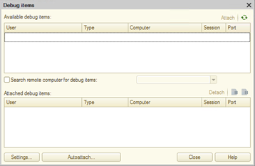
Fig. 554. Debug items
The following is excluded from the Available debug items list:
-
Attached debug items (displayed in the Attached debug items list).
-
The debug items that do not match the filter set at the top right part of the window. Filter is intended only for the visual limitation of the list. Debug items that do not match the filter are still available for use and, after turning off the filter, will instantly appear in the available debug items list.
When you click Attach, the selected debug item is attached to the Debugger. In the attachment window, this is displayed by the transfer of the debug item from the list of available debug items to the list of attached debug items.
To exclude a debug item, you need to specify it in the list of attached items and click Detach. In the attachment window, this is displayed by moving the debug item from the list of attached items to the list of available items. You can re-attach to it. Moreover, breakpoints set in detached debug items will not "work" when passing through them.
To close the debug item, click Finish. To stop at the execution point, click Stop.
To open a dialog box with information about the debug server being used, click Settings. In the opened dialog box, the debug server address and the name of the infobase will be displayed.
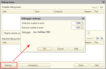
Fig. 555. Debug server information
To automatically attach debug items to the current debugger, you can use the Auto attach dialog box and configure the required filters in it.
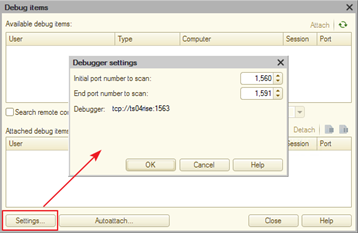
Fig. 556. Filter debugging items for automatic attachment
On the left part of the dialog box (Types of debug items), you can specify which types of debug items will automatically attach to the current debugger straight after registration on the used debug server. You can select several types of debug items. If the type of debug item is marked as the Background Job, this means that as soon as the 1C:Enterprise server, which is running in debug mode, starts the background job, it will automatically be attached to the current debugger.
On the right part of the dialog box, you can specify an additional filter of debug items (Filters of debug items). The additional filter of debug items, in addition to specifying types of debug items, also includes the filter by users, as well as by the values of separators.
A debug item will be automatically attached to Debugger if it matches one of the enabled filters. This debug item matches the filter by item type, runs on behalf of the specified or one of the specified users, and the separators are set to the specified values.
The filter that is configured in the Automatic attachment of Debug Items on the debug server dialog box, combines a filter by debug type and by debug item filters "by OR". So the debug item will be automatically attached if it matches one of the set debug types OR matches one of the enabled filters.
The values set in this dialog box start working immediately and until the next change of settings.
A common list is used to filter available debug items.
31.2.2.2.4. Debug server
General information
Debug server (dbgs) is an application that acts as an intermediary between the debugger and various debug items (see How it works).
The debug server can be started in several ways:
-
From Designer, when debugging an application in file mode.
-
From server cluster, if debugging mode is enabled for the cluster.
-
From application developer, if it is necessary to implement complex debugging scenarios. In this case, you can also register the debug server as an operating system service (for Windows OS) or start it as a "demon" (for Linux OS).
In case the debug server is started by other components of the 1C:Enterprise, all the necessary settings of the debug server are automatically configured by these components.
Getting the debugger address
To retrieve the address of debug server for interacting with the Designer debugger, you need to perform the following steps:
-
Open the dialog box for attaching debug items: Main menu – Debug – Attach.
-
Click Settings.
-
Copy information from the Debug Server: line.
Test the debug server performance
The debug server performance can be tested as follows:
-
Retrieve the address of the debug server, for example, in Designer.
-
Enter the obtained address in the address bar of any web browser.
-
The debug server is functioning normally if the web browser displays the following information:
1C:Enterprise 8.3 Debug Server (8.3.7.1140) © '1C'
1996 2015 - it works!31.2.3. Breakpoint
31.2.3.1. General information
A breakpoint is a place in the program module where module execution stops and control is taken by the Debugger.
The current breakpoint, break locations and breakpoint statuses are shown in the left column of the module text, with special marks.
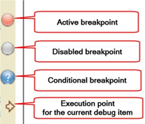
Fig. 557. Breakpoint types
The following objects are numbered in fig. 557:
-
Breakpoint without any parameters.
-
Disabled breakpoint (with any parameter state).
-
Breakpoint with specified trigger conditions.
-
Unconditional breakpoint with specified actions.
-
Breakpoint for which both trigger conditions and action are specified.
-
Pointer to the current execution string.
You can set breakpoints in any module line at any time during debugging. The only exception is that it is impossible to set a breakpoint for a module text that was added after the last save and was not saved. If the line with a breakpoint does not contain any operators (for example, an empty line) or contains non-executable text (for example, procedure or function header or variable definition), or is a continuation of the operator started on previous lines, the breakpoint position is automatically adjusted. Breakpoint position is marked with a special character in the left column of the module window. Different characters are used for different breakpoints (see fig. 557).
The mouse can also be used to set or remove breakpoints. To do this, double-click in the grey area of the line where you want to set the breakpoint. To remove an enabled breakpoint, double-click it. To enable a disabled breakpoint, double-click it.
Use the following commands of the Debug menu in the Designer main menu to manage breakpoints.
| Command | Description |
|---|---|
| Breakpoint | Sets or removes a breakpoint on the line where the cursor is set. |
| Breakpoint with parameters | Sets a breakpoint and opens the dialog box for adding a break condition – a logical expression. If the condition has been added, a dialog box opens to edit the condition. If a breakpoint has been set on this line, a dialog box opens for setting a breakpoint condition for the breakpoint with the condition. Execution stops at the specified breakpoint only if all the breakpoint conditions are met. |
| Stop on error | If an error occurs, the debugger stops execution and proceeds to the module line that caused the error. You can specify what text must be included in the error message so that execution stops when the error occurs. |
| Disable breakpoint | Enables or disables the breakpoint. The command is available if the current line has a breakpoint. |
| Remove all breakpoints | Removes all previously set breakpoints in all modules. |
| Disable all breakpoints | Disables all previously set breakpoints in all modules without deleting them. |
| Breakpoint list | View and manage breakpoints. |
| Move a breakpoint up | Moves the current breakpoint up one string. |
| Move a breakpoint down | Moves the current breakpoint up one string. |
| Cut a breakpoint | Copies the breakpoint characteristics to the clipboard and removes the breakpoint in the current string. |
| Copy a breakpoint | Copies the breakpoint characteristics to the clipboard. |
| Paste a breakpoint | Creates a breakpoint in the current string with parameters that correspond to the breakpoint parameters in the clipboard. |
31.2.3.2. Breakpoint parameters
You can create a breakpoint with parameters using the Breakpoint parameters dialog box.
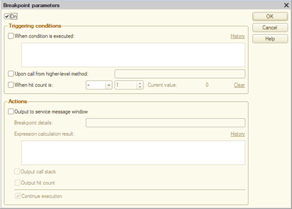
Fig. 558. Breakpoint parameters
Using this dialog box, you can manage the following main breakpoint parameters:
-
Whether the breakpoint is enabled or disabled (the Enabled checkbox).
-
Under what conditions the breakpoint will be triggered (the Triggering conditions parameter group).
-
What will happen when the breakpoint is triggered (the Actions parameter group).
If the breakpoint parameters are set as on fig. 558, this corresponds to an unconditional breakpoint, which causes execution to unconditionally stop when it hits this point.
If you clear the Enabled checkbox at any breakpoint, the breakpoint becomes disabled. In this case, Designer will retain all the breakpoint parameters, but the breakpoint will never cause execution to stop. For a breakpoint to have an impact on executing 1C:Enterprise language code, it must be active (the Enabled checkbox is selected).
To describe a breakpoint, the term "hit" will be used. This term is used in the situation when all the conditions specified for the breakpoint triggered, which led to the need to stop at the breakpoint.
Let's have a look at possible breakpoint conditions. There are several possible triggering conditions. If several conditions are specified, they are combined by "AND": for a breakpoint to be triggered, all the specified conditions must be met.
The When condition is executed condition allows you to specify an expression in 1C:Enterprise language. The condition will be met if the expression returns True. Designer remembers the last 15 conditions. To access the history of expressions, click History above the upper right edge of the expression input field.
The Upon call from higher-level method condition allows you to specify a name of a method that the call stack must contain to trigger the breakpoint. You can use regular expressions to specify the method name. The ICU dialect is used. Using this condition, you can trigger a breakpoint only when a method with a breakpoint is called indirectly from a defined method and does not trigger when called from any other method in the application. It is important that the method name is checked by the whole stack in this debug item, not only at the level from which the method with the breakpoint was called. It means that if a breakpoint with such condition is set in server code, the check is performed starting from the first method called on the server and is not performed on the client.
With the When hit count is condition, you can specify the number of breakpoint hits and a condition for this number that must trigger the breakpoint. Possible conditions: equal, greater than or equal to, less than or equal to, and multiple of. The value is specified in the corresponding field. The current hit counter is displayed to the right of the condition. To clear this value, click Clear to the right of the current hit count. The current hit counter is also cleared in the following cases:
-
When a disabled breakpoint is enabled.
-
When debugging is restarted, hit counters are cleared for all breakpoints.
After you set the conditions for triggering a breakpoint, you can specify what the debugger must do if the breakpoint is triggered. By default (if no actions are selected in the Actions group), the execution is stopped.
Select the Output to service message window checkbox to record breakpoint hits in the debug protocol. If you specify a breakpoint name in the Breakpoint details field, when a breakpoint is hit, its name will be displayed in the message window along with internal data: a module name, a module line, a client name, and server parameters.
If you specify an expression in the Expression calculation result field, when a breakpoint is hit, the calculation result of the specified expression will be displayed in the message window. The result is output as a string presentation of the expression evaluation result. To title the result, specify the required title before the expression according to the rules for generating an expression to get a string. For example, when a breakpoint is hit and you need to display the result of 22 expression with the "22=" title, put the "22=" + (22) expression in the Expression calculation result field. In the upper right corner of the Expression calculation result field, you can find the History hyperlink. Using this hyperlink, you can access the 15 most recently edited expressions.
If the expression cannot be evaluated, a standard error message is displayed in the message window indicating that the expression cannot be evaluated.
If the Output call stack checkbox is selected, when a breakpoint is hit, a call stack of 1C:Enterprise language will be displayed in the message window. It allows you to find out how the application got to this application area. The stack is displayed from a method where the triggered breakpoint is located up to the first method called by a platform when performing the operation.
When you output a stack, one line describes one method. The line looks as follows: ModuleName, MethodName(ParametersList), LineNumber, where:
-
ModuleName. Full name of the module with the method.
-
MethodName. Name of the method in the module from which the call was made.
-
ParametersList. Actual parameter values used when calling the method. Each parameter is described by the Name=Value pair. Primitive types are output as actual values, complex types are displayed as type names.
-
LineNumber. Number of the module line with the method call location.
For example, consider the following stack:
ManagedApplicationModule.ShowValues(Value
= Array), 2
ManagedApplicationModule.OnPasteFromClipboard(Value
= Array), 32In this stack, you can see that the breakpoint is in the second line of the ShowValue() method of the application module. This method is called from the OnPasteFromClipboard() method of the application module. The call code is located on module line 32.
Select the Output hit count checkbox to find out how many times 1C:Enterprise language execution hit the breakpoint.
Select the Continue execution checkbox to manage debugger actions when the breakpoint is hit. If the checkbox is cleared, the breakpoint works as follows: if the conditions listed in the Triggering conditions group are met, code execution in 1C:Enterprise language stops and the result of the actions specified in the Actions group for the breakpoint is displayed in the message window.
If the Continue execution checkbox is selected and the conditions specified for the breakpoint are met, the results of all these actions will be displayed in the message window and execution will continue without stopping. Thus, to analyze complex errors, you can place breakpoints in the code being debugged with parameters that are configured to display a debug protocol in the message window but not to stop execution. You can then reproduce the error and analyze the resulting debug protocol.
You can "click" all debug protocol strings displayed in the message window. You will be navigated to the method (and module) whose reference was specified in the message.
When the breakpoint is triggered, the following information is displayed in the message window:
BreakpointDetails ModuleName, LineNumber[(TriggerCount)] (Type: [User](SessionNumber), Computer: Port)In this description:
-
BreakpointDetails is one of the following:
-
If only breakpoint details are specified, the specified details are displayed.
-
If only an expression to calculate is specified, the expression calculation result is displayed.
-
If both details and an expression are specified, breakpoint details are displayed, followed by the ":" character and the expression calculation result.
-
Otherwise, the Breakpoint triggered text is displayed.
-
-
ModuleName. Full name of the module where a breakpoint triggered.
-
LineNumber. Line number in the ModuleName where a breakpoint is located.
-
HitCount. It is displayed if the Output hit count checkbox is selected.
-
Type. Debug item presentation.
-
User. Name of the user on whose behalf the session is running (if users are specified in the infobase).
-
SessionNumber. Number of the infobase session where a breakpoint triggered.
-
Computer:Port. Name of the computer and a number of the network port where the infobase session to debug is located. You can find the debug item details in the Type field.
See also:
- Regular expressions
31.2.3.3. Breakpoint list
Set breakpoints are saved when the configuration is closed. To view the list of breakpoints, open the configuration and click Debug – Breakpoint list.
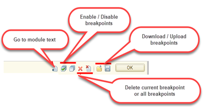
Fig. 559. Breakpoint list
In fig. 559, the following buttons are numbered:
-
Click the button to open the Breakpoint parameters dialog box.
-
Click the button to go to the module line with the current breakpoint. This button opens the corresponding configuration module.
-
These buttons enable or disable all breakpoints in the application at once. If you want to enable or disable several breakpoints, select them (click and press Ctrl), and select or clear the Enabled checkbox in one of the selected lines.
-
This button deletes the current breakpoint. To enable or disable the breakpoint, select or clear the checkbox in the Enabled column of the breakpoint list.
-
Use this button to delete all breakpoints in the application.
-
With these buttons, you can save breakpoint settings to the XML file and import breakpoints from the XML file.
Select or clear the checkbox in the Enabled column to manage the state of the selected breakpoint. If the checkbox is selected, the debugger will process the parameters of this breakpoint while it runs. Otherwise, the breakpoint will be ignored.
TheTriggering conditions and Actions columns contain a brief description of the respective breakpoint parameters. In the breakpoint list window, press ENTER or 2 (fig. 559) to navigate to the module line with the breakpoint. In the breakpoint list window, press F2 or 1 (fig. 559) to open the dialog box where you can edit breakpoint parameters.
The breakpoint list window can be displayed in different modes.
31.2.4. Step-by-step execution
In the step-by-step execution mode, the debug item completes each command and waits for a debugger command to continue execution.
When the first debug item is attached, the system adds debug management commands to the Debug menu.
There are several options for each step of module execution. Use the following commands from the Debug menu to select an option.
| Command | Description |
|---|---|
| Step In | If the next executable module operator is a function or procedure call, it is incrementally executed, otherwise the debugger proceeds to the next operator. |
| Step over | If the next executable module operator is a function or procedure call, it is executed completely (not step by step), and the debugger proceeds to the next operator. |
| Step Out | Interrupt incremental execution of a function or procedure and stop at the first operator after it is called |
| Go to cursor | Interrupt step-by-step module execution, execute all statements up to the line where the cursor is set |
| Continue | Break the step-by-step module execution and continue free execution |
When you debug applications, keep in mind that if there is the Execute() operator in the program code to debug, then:
-
Step-by-step execution of the program code passed as an operator parameter (including procedure and function calls) is not supported.
-
Interruption of program code execution using breakpoints located inside procedures and functions and called from the program code passed as the Execute() operator parameter is supported.
If you debug multiple debug items, then there is a number of features of incremental implementation:
-
If you stop a debug item, other debug items are also stopped when you execute the code.
-
If you select Continue, it resumes execution of all debug items.
-
If you select Step Over, it proceeds to the next line for all debug items.
-
If you select Step In (if the executable module operator calls a function or a procedure), it proceeds to the first operator in the call, while the Step Over command is performed for other debug items.
If you debug the client/server mode and the code is sequentially executed on the client and on the server (client and server debug items are attached), then:
-
If you select Step In (if the executable module operator calls a function or a procedure on the server), it proceeds to the first operator in the call.
-
If you select Step Out or Step Over for the last executable operator (if the executable module operator calls a function or a procedure executed on the server and called from the module executed in the client application), it proceeds to the next executable operator in the call.
The current debug item can be selected in a special Debug Items toolbar. The toolbar has the only selection field displaying the current debug item. The selection field is only accessible when the Debugger controls one of the attached debug items (for example, after the breakpoint is triggered). The list of debug items only contains items that are currently controlled by the debugger, including the current debug item.
Use the immediate window and the Expression dialog box to get values for the relevant expressions (see "Expression" window). Call stack can be used to trace the sequence of call procedures and functions.
If a step-by-step process is performed, the call stack and variable values (in the immediate window and the Expression dialog box) are displayed for the current debug item. When you change the debug item, it also changes the call stack and variable values.
Note. NOTE. If the client and server debug items are attached, and the transition is made from the client to the server, then no calculations are made at the client levels of the call stack. These levels are highlighted in gray in the call stack window.
If you need to continue the module execution, select Debug – Continue debugging to enable free module execution for the attached debug items (up to the next breakpoint). If a client application is attached for debugging, it is activated automatically.
To interrupt the entire debugging process (except for background jobs), remove all breakpoints from all modules and run the Debug – Continue debugging command, if a breakpoint has been triggered. To interrupt debugging and terminate the operation of the attached debug items, use the Debug – Finish command. In the latter case BeforeExit() and OnExit() procedures are not executed.
You can edit the current configuration and save changes during debugging.
Note. NOTE. Although during the debugging process it is possible to edit the module being debugged, the debugger does not compile the changed code debugging is continued for the database configuration code (at the moment when debugger is started or attached). To debug the changes made to the configuration, you should update the database configuration.
If exclusive mode is set in 1C:Enterprise mode, you will not be able to save the current configuration until the exclusive mode is removed.
If a file infobase is in the state of stepping through 1C:Enterprise language code or is at a breakpoint, and there is an open transaction (explicit or implicit), executing some operations (for example, an attempt to lock objects in the configuration repository) may cause an error: Configuration repository operation failed. (Error while collecting information for the configuration repository) Lock conflict during the transaction. Could not lock FILES table. It is recommended that you shut down the client application before retrying. To perform the operation during which an error occurred, you should continue 1C:Enterprise language code execution until the transaction is completed.
Table of key combinations for debugger operations can be retrieved in Help when using the application.
31.2.5. Debugging external data processors (reports)
To debug external data processor (report) modules, you have to open the external data processor file in Designer using the File – Open item.
In the future, you can work with external data processor (report) modules in Debugger just like with any other module.
31.2.6. Debug management
Debug – Restart command stops configuration execution and restarts it in 1C:Enterprise mode. If configuration has been modified, the screen prompts you to update the database configuration.
Debug – Finish command stops module execution and terminates the operation of the current debug item.
Debug – Stop command stops module execution on the current operator. This command can be used to start module debugging from the next executable string. This command is useful for module "cycling" analysis.
Debug – Stop on error command opens the stop on error settings dialog box.
Select the Stop on error checkbox to stop debugging if an error occurs during execution. When debugging stops due to an error, you will see the Runtime error warning and information about the location and cause of the error.
If Stop on errors containing text checkbox is selected, then debugging is stopped in the place of an error (if the error message contains the substring indicated in the table field). If this checkbox is not selected, debugging stops on an error regardless of the error message text. At the same time the specified substring is considered only if you select the checkbox next to it.
At the place of error, the current execution point of the current debug item is set, and the debug item where the error occurred becomes the current one. Viewing expression and variable values is used to determine the cause of the error. The error message text at such stop will be placed in the message window. To go to the error location, double-click the error text or press ENTER.
31.2.7. "Expression" window
During the step-by-step execution, Expressions can be calculated using the Expression window. This window is displayed by selecting the Debug – Calculate expression item.
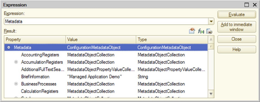
Fig. 560. Calculate expression
Add the expression in the 1C:Enterprise language into the Expression field of this window. You can add the expression "manually" or select it from a list of previously added expressions.
If the cursor in module window was placed over an expression or an expression was selected when calling the Expression window, the expression is automatically inserted into the Expression field.
Click Calculate to calculate an expression. The expression calculation result will be displayed in the Value field. Note that expressions are calculated in a real system, so various side effects are possible. For example, if the calculated expression analyzes the presence of some item in the infobase, and creates the necessary item in its absence, such expression will be executed "along the way" of creation only once. This is due to the fact that after the first execution, the necessary item will be created in the real infobase.
The Include in immediate window button adds the expression entered into the immediate window. This may be used to trace the change of calculation result of the expression in the process of module debugging. In this case, the expression is placed into a new line of the immediate window. If there is no immediate window on screen, it opens.
If an expression has a String type or is a collection of values or an array, the tools panel button Show Value in separate window becomes available.
For the convenience of viewing long strings, the View Expression value window is displayed. This window contains a control of Label type that displays the line value for viewing.
For the convenience of viewing a collection of values or an array, a window containing a table field is opened, columns in this window correspond to attribute names and rows contain attribute values. The window also shows the number of items in a collection and the first column indicates the index of each collection item.
If a specific value is also a collection of values or an array or a row, you can view these values in a separate window (as shown on fig. 561). To do this, select the required value in the context menu and select the Display value in separate window item or press F2.
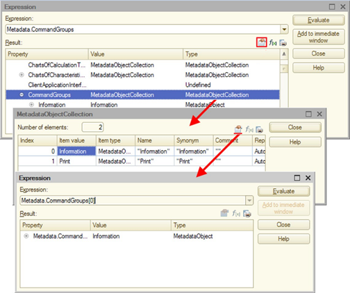
Fig. 561. Display values
For a string, a window is displayed with the string expression value in a multiline field. You can copy this expression to the clipboard.
The contents of the calculation result table field can be exported to a text or a spreadsheet document using the Output list button. If the calculated value is represented as a tree, you can only export data from the opened strings of this tree.
The current value of the expression can also be viewed by moving the cursor over the expression. The current value is displayed as a short tooltip next to the variable. Viewing is possible if the value has a textual representation. This way can also be used to view the value of the property. If the property is represented as <Object>.[<Object>.…]<Property> (for example, Controls.CommandBar.Buttons.Get.Enabled), to view the value, hover the cursor over such text. The value is displayed if the text does not contain parentheses or square brackets. You can also view the value of the array element whose index is explicitly specified as a number or variable with the value determined at the time of viewing. To do this, you need to select the array ID and index.
When hovering the mouse pointer over a single object, a selected object, or a group of objects in the text of the <Object>.[<Object>. ...] <Property> type, its type is shown. For example, if selecting Controls.CommandBar1 in Controls.CommandBar1.Buttons.Get.Enabled text, the CommandBar type will be displayed.
31.2.8. Immediate window
Immediate window is a specific window that displays calculation results for variables and formulas that have been entered into it during debugging. Call of immediate window on screen is performed by selecting the Debug – Immediate window menu item, available when debugging.
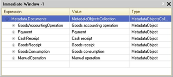
Fig. 562. Immediate window
Immediate window is a four-page form. Each page of the form contains a table box to add variables and formulas whose calculations results should be controlled. Formulas can include arithmetical expressions and expressions with 1C:Enterprise language functions as well as the module functions of the managed application and common modules.
Each formula is entered in the first table column, in a new row. The result of the formula is displayed in the Value column. The Type column displays the type of expression. If the formula is incorrect, you will see the following error message instead of the result: Syntax errors detected!
Immediate window and calculation results are managed using the context menu commands.
The calculation result can be copied to the clipboard by selecting Copy result of the second column context menu.
For some data types (see the previous section) it is possible to view the values in a separate window.
Immediate window can also be output to a spreadsheet or text document.
If the formula data source changes, you have to recalculate the result. To recalculate a single value, right-click a formula and click Recalculate. To recalculate all values, right-click anywhere in the immediate window and click Recalculate All.
The immediate window has two modes for page selection. In the first mode, select pages using the tabs located at the bottom. In the second mode, select pages using the context menu. You may select the mode by checking or unchecking the Tabs option in the context menu.
To clear the line in the immediate window, select the line and press Del.
The immediate window may be displayed in different modes. After debugging is complete, the window closes automatically.
31.2.9. "Local variables" window
During debugging, it is possible to open a special window that contains a list of local variables of the current method, where the current execution line of the 1C:Enterprise language is located. The window is called up by selecting the menu item Debug – Local variables, which is available during debugging.
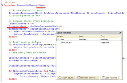
Fig. 563. Local variables window
The local variables window contains the parameters of the method being debugged and all local variables used in the method at the current level of the call stack (by default, at the top of the call stack). At the very beginning, the variables are in the uninitialized state. As they are assigned any values, these values appear in the local variables window. The order of the variables in this window is undefined. You cannot edit the Variable column in this window. The rows composition in this window is not available for editing.
Switching on the call stack, changing the debug item, as well as updating the window contents will be made automatically after each action performed during debugging.
The calculation result can be copied to the clipboard by selecting Copy result of the second column context menu.
For some data types (see the previous section) it is possible to view the values in a separate window.
Immediate window can also be output to a spreadsheet or text document.
The local variables window can be displayed in various modes. After debugging is complete, the window closes automatically.
31.2.10. Variable value change
When the debugger stopped at a breakpoint, it is possible to change the values of variables and properties of objects available for writing. You can access the change function from the expressions window (see "Expression" window), immediate window (see Immediate window), and the local variables window (see "Local variables" window). In the expressions window, to change the value of a variable, hover the mouse pointer over this variable and click f(x). In the immediate window or the local variables window, select Set new value as an expression in the context menu of a specific variable. The term "variable" refers to not only the value of an ordinary variable, but also the property of the collection (arbitrary nesting).
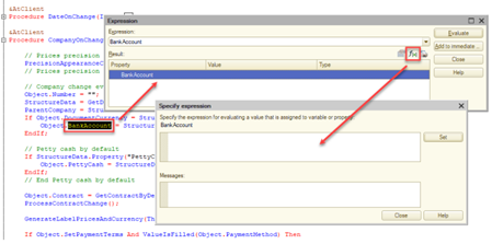
Fig. 564. Variable value change
After calling the value change function, a special window is displayed for entering the expression. In the upper part of the window, enter the expression which value will be set to the variable. Name of the variable is represented by the header of the expression input field. In the example in fig. 564 it is proposed to change the value of the variable Course.
In the expression input window, you can enter constant values of various types, as well as any expressions that are correct in the 1C:Enterprise language. There is a context help in the expression input window that displays the context of the debugger current method.
After clicking the Install button, the installation result will be displayed at the bottom of the expression input window. This could be a phrase The value was successfully changed, or an error message if there is one.
The variable value can be changed directly in the window where the variable value is displayed. To do this, double-click the left mouse button on the text in the Value column. Please remember, that in this way you can only set the value of primitive types.
It must be clearly understood, that the possibility of changing the values of variables during debugging can lead to various unpredictable consequences in the operation of the information system. So, if in the process of debugging, for an object recorded to the database (for example, in the BeforeWrite() handler), you can set the property values that cannot be there during actual system operation. However, these incorrect values will be written to the database. At that, other system algorithms may not work correctly. In this regard, you should cautiously use the option of changing the variable values and object properties during debugging.
31.2.11. Call stack
Call stack shows the sequence of procedure and function calls that led to the currently debugged module line.
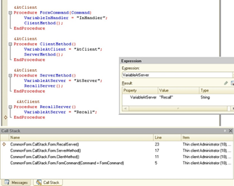
Fig. 565. Call stack
The window shows:
-
Executable method. The Name column.
-
Module line number. The Line column.
-
Debug item where the module is located. The Item column.
The first column of the window can have two icons:
-
The yellow arrow indicates the top of the call stack.
-
The green arrow (to the left of the CommonForm.CallStack.Form.ServerMethod() line) indicates a method in whose context variables are calculated in the Expression window and the Immediate window. If the top of the call stack matches the current context, the green arrow is not shown. To change the context and to set the cursor position to the row indicated in the Row column, double-click the required row in the Call Stack window.
In the example shown in fig. 565, the VariableOnServer variable has the OnServer value, since the debugger is switched to the ServerMethod() method context (as indicated by the green arrow next to CommonForm.CallStack.Form.ServerMethod()).
If you switch the context to the top of the stack (double click the row with the yellow arrow), the value of the VariableOnServer variable is set to Recall, because the context switches.
Some rows in the Call Stack window are shown in grey (the last two rows in fig. 565). This means that you can switch to a module line, but you cannot evaluate expressions in the context of the called method. Thus, those stack items are selected that are "located" on the client, and the top of the stack is "located" on the server.
31.2.12. Debugging protected modules
If the module line calls a procedure or a function located in a protected module (see Configuration modules access restriction), and you use the Step in command at the first attempt to go to the selected procedure or function, the debugger prompts you to enter a password.
If you enter the password correctly, the debugger opens the protected module and control passes to the first line of the called procedure or function. When you address to the protected module again in this session, no password is requested.
If you cancel the password entering, the debugger skips the protected code (but still executes it) and proceeds to the first code line following the protected module. Similarly, the command Step Out is executed.
The procedures and functions names are always specified in the call stack. If the protected module has not yet opened, then the first time you attempt to go to the selected protected module procedure, the debugger asks for an access password. Upon subsequent transitions to a protected module from the call stack, the password is not required (in the current session).
31.3. Runtime errors
31.3.1. General information
You can catch and process some errors (recoverable errors) and cannot catch some other errors (non-recoverable errors), but can display any error to the user. We recommend that you do not disable the display of errors as it results in masking issues instead of solving them.
This section describes how you can:
-
Get error information, analyze the exception stack, and identify exception category from the list.
-
Configure error message texts and generate error reports.
-
Catch any error messages to display error information and generate an error report.
See also:
-
Exceptions in 1C:Enterprise language (see Operations with exceptions).
-
Recoverable and non-recoverable error (see Using explicit transaction call).
31.3.2. Displaying errors
Runtime errors, which occur during the application runtime, are displayed depending on whether the error is recoverable or not, as well as on debug and technician mode states.
If a recoverable error is detected, a dialog box that contains error details and the OK button is displayed. If a non-recoverable error is detected, a dialog box that contains the Exit and Restart buttons is displayed.
In addition to text and buttons, the error dialog box might contain the Generate error report hyperlink in the lower right corner. Whether the hyperlink is displayed or not depends on the error category.
The error dialog box displays a text whose content for the same error depends on the technician and debug modes. If the client application is running with disabled debug and technician modes, the dialog box displays the error presentation for a user. This presentation depends on the error category. If technician mode is enabled, the dialog box displays a detailed error text.
For example, if the "Division by 0" error is detected with disabled debug and technician modes, it is displayed as follows:
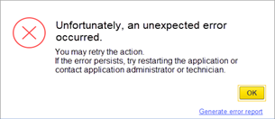
Fig. 566. Error with disabled debug and technician modes
If technician mode is enabled, the same error is displayed in a different way: the dialog box text contains the actual error message without additional processing:
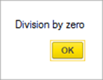
Fig. 567. Error in disabled debug mode
If the client application is running in debug mode, or the mobile version of 1C:Enterprise platform for developers is used, the error report contains the actual error message without additional processing. Besides, the dialog box contains the Detailed button.
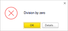
Fig. 568. Error in enabled debug mode
If you click Detailed, the dialog box opens:
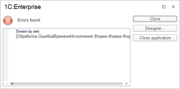
Fig. 569. Error details
This dialog box contains all available error information, including the call stack. You can also close the system (click Log out) and go to Designer to the string where the error occurred. To open Designer, click Designer.
If the error is network-related, the notification dialog box looks slightly differently:
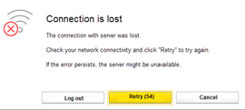
Fig. 570. Connection is lost
In this dialog box, you can repeat the action or log out. The operation will be repeated every minute. There is a counter on the Retry button. If you click Cancel, the standard network error dialog box opens instead of the connection error dialog box:
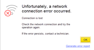
Fig. 571. Network error
If a network error occurs when accessing the infobase upon direct connection to the server cluster or connection over HTTP, and you can retry the uncompleted action, the system checks whether the server cluster is available every 10 seconds. Once the cluster becomes available again, the error message window closes, and the user receives the notification:

Fig. 572. Notification of restoring connection
After the user receives this notification, they can completely repeat the interrupted operation.
31.3.3. Error information
If an error is recoverable, you can handle it using the Try ... Except statement. When you catch an error using the Try ... Except operator, you can use several methods to get the error report:
-
ErrorInfo(). Use this function to get the ErrorInfo object that describes the current error.
-
ErrorProcessing.BriefErrorDescription(). Use it to get a brief error description. As a rule, this is the text that the platform returned as a description of the first error in the stack. The text is without details and represented as a module name, a line number, and text in 1C:Enterprise language that caused the error.
-
ErrorProcessing.DetailErrorDescription(). Use it to get a detailed error description. Generally, this is a text that contains information about the current error and all the errors that caused the current one. This information will contain error details, as well as technical details such as module name, line number, and text in 1C:Enterprise language. The initial error will be at the end of the text. The current error will be at the beginning of the text with error presentation.
-
ErrorProcessing.ErrorDescriptionForUser(). Use it to get only an error description without recommendations and in the way the user sees it. In fact, this is a brief error presentation that does not contain any information that may seem difficult to understand. For example, the error presentation will not contain a reference to SDBL or an object whose method was not found.
-
ErrorProcessing.ErrorMessageForUser(). Use it to get an error description as the user sees it in the error display dialog box. This message includes an error presentation and some optional recommendations.
Let's take a closer look at the ErrorInfo object. To get this object, use the ErrorInfo() function in the exception handler only. The object contains the following properties:
-
Description. Text error presentation generated by the platform.
-
Code. Contains a string that can be used to identify an exception (error) generated by the application code.
-
Cause. Object of the ErrorInfo type that describes the error that caused this error. Use this property to learn more about the exception stack and get the entire causal relationship for the error.
-
ModuleName contains a full name of the module in 1C:Enterprise language where the error occurred, which is described by this object. A module line number and a particular 1C:Enterprise language string are in the LineNumber and InitialString properties, respectively.
-
AdditionalInformation. A string that contains additional information that can be specified for an exception.
To classify errors, use the ErrorInfo.IsErrorOfCategory() method. To set error categories, use the ErrorCategory system enumeration. To filter exceptions generated in 1C:Enterprise language by the Raise operator, use the ErrorCategory.ExceptionRaisedFromScript category.
Keep in mind that the categories will expand over time. In other words, next platform versions may have a category of errors that the current version does not have. Don't forget that an error may later belong to a different category.
See also:
- Exceptions (see Operations with exceptions).
31.3.4. Error display processing
To catch errors, use the Try ... Except operator. In this case, the application developer who implemented the exception handling informs the user about errors. If the error is not caught, the developer can still take control before the error message is shown to the user.
To gain such control, implement the ErrorDisplayProcessing event handler in the application module. The handler is called when an uncaught exception is thrown, but before the user sees the error window. In the handler, the application developer can perform some additional error-related actions. They can modify the error message text, send the error report to some service that aggregates error logs within the network, and so on. The event handler runs on the client application side. So when errors of some categories occur (for example, a network error or session deletion), you cannot access the server (for example, to get a form). So, we recommend that you ensure only client objects and methods of 1C:Enterprise language are available in the ErrorDisplayProcessing event handler, which do not result in an explicit or implicit server call. In such cases, to display information to the user, use the ShowMessageBox() or ShowNotificationToUser() method. If you call the ErrorDisplayProcessing event to process a non-recoverable error, use the ErrorProcessing.ShowErrorInfo() method and client methods of the ErrorReport object to display the error.
Let's take a look at parameters of the ErrorDisplayProcessing event handler:
-
ErrorInfo. ErrorInfo object that contains all available information about the error whose message is planned to be shown to the user.
-
SessionTerminationRequired. Indicates that information about a non-recoverable exception will be displayed (the parameter is set to True), and the system will be terminated after the handler termination is displayed.
-
StandardProcessing. If this parameter is set to True, then, after the event handler is completed, the standard error message form will be shown.
If an unhandled exception is thrown inside the ErrorDisplayProcessing event handler, the handler will be completed. The further behavior depends on whether debugging is enabled in the client application:
-
Debug mode is disabled. The user will be shown a standard dialog box with information about the error that led to the ErrorDisplayProcessing event handler.
-
Debug mode is enabled. The user will be shown a standard dialog box with information about the uncaught error.
Let's take a look at the whole process of error processing in the ErrorDisplayProcessing event handler. Having gained control in the event handler, you can determine the severity of the error by the SessionTerminationRequired parameter. If this parameter is set to True, the handler code is the last application code that will be executed before the client application is closed.
If you are in this handler, it means that information about this error has already been written to the platform event log. Since the server call is most likely unavailable, you cannot use the platform event log to record some additional information. However, you can use any external logging tool. To access it, use client tools of any client application. Keep in mind that a network error may prevent you from using external tools.
Now let's find out how the error message is shown to the user. If you want the platform to decide on the message, set the StandardProcessing parameter to True before you leave the handler. If you want to generate the error text on your own and show it, set the StandardProcessing parameter to False and generate an error presentation.
To generate the error description, use two concepts:
-
Error presentation is a text that is generated based only on the ErrorInfo object. The text contains only the information available from the exception stack.
-
Message to the user is a text that contains the error presentation and some instructions for the user. The message to the user is generated based on custom templates. To learn how to customize templates, see another section.
Basically, if you have the ErrorInfo object, you can generate an arbitrary error presentation. However, we do not recommend that you do this. We recommend that you show the error text generated by the platform. You can generate the message to the user quite arbitrarily. For example, you can choose not to include the error presentation there.
So, use the ErrorProcessing.ErrorDescriptionForUser() function to get the error presentation text. The ErrorProcessing.ErrorMessageForUser() function returns an error message that you can immediately show to the user.
Now you have everything you need to display the error. Let's decide how to display it. In the simplest scenario, you can show a standard dialog box generated by the ShowMessageBox() method. However, this dialog box appearance differs from the one shown by the platform automatically. Moreover, you cannot send an error report. So, we recommend that you display the error using the ErrorProcessing.ShowErrorInfo() method.
If everything is correct, the error will be shown in the following window:
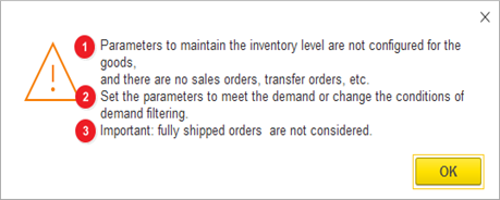
Fig. 573. Form with an error
In the form, the numbers indicate the following objects:
-
"Error presentation for a user".
-
The fragment of the message to the user that contains instructions for the user. The ErrorProcessing.ErrorMessageForUser() function returns strings 1 and 2 as a single string.
-
The value of the AdditionalInformation parameter of the ErrorProcessing.ShowErrorInfo() method.
-
This hyperlink will be displayed if the GenerateErrorReport parameter of the ErrorProcessing.ShowErrorInfo() method is set to True.
The dialog box displayed in fig. 573 is created by a very simple event handler ErrorDisplayProcessing:
Procedure ErrorDisplayProcessing(ErrorInfo, SessionTerminationRequired, StandardProcessing)
StandardProcessing = False;
ErrorProcessing.ShowErrorInfo(ErrorInfo, ErrorMessageDisplayVariant.ErrorMessageForUser, "Additional information is
displayed here", True);
EndProcedureSee also:
-
Recoverable and non-recoverable error (see Using explicit transaction call).
-
Setting up error message templates (see Setting up error processing).
-
Error report.
31.3.5. Infobase access error
Errors that occur upon signing in to the client application are very difficult for an ordinary user to understand. Generally, such errors are caused by:
-
Technical problems with the network. For example, the user cannot connect to a server or an infobase.
-
Infobase maintenance. Such errors include exclusive infobase lock, session start lock, denied access from the external session management service, licensing error, and so on.
As a rule, texts of these errors do not provide any useful information to most users. However, they can be very useful for technicians. This section describes how to create error messages that contain clear and simple instructions for users.
Error messages are generated by the system and depend on the error category. For detailed setup of error messages, use the standard Management of error processing settings function or a similar feature available from 1C:Enterprise language.
On the platform, you can also set up several additional characteristics for such errors. To do it, use the ErrorOnStartupProcessingSettings object. You can do the following:
-
To set up additional text to be displayed in the dialog box with the application sign-in error, use the HelpText property. The text can be a regular string or a value of the FormattedString type.
-
To set the URL to follow to access help information, for example, the list of frequently asked questions (FAQ), use the HelpURL property. If this property contains a value, the connection error form displays the Need Help? button. Click the hyperlink to follow it. The URL must contain a protocol. For example, https://example.com or http://example.com.
-
To set the HTTP service address to which you can send a GET request to get additional information about the issue, use the ErrorOnStartupProcessingServiceAddress property. The description of this service will be given below.
-
To specify additional information to be transferred in the request header to the processing service of startup errors, use the AdditionalRequestInformation property.
After all the required properties of the configured object are filled, send it to 1C:Enterprise platform. To do this, use the ErrorProcessing.SetErrorOnStartupProcessingSettings()method. To get current settings, use the ErrorProcessing.GetErrorOnStartupProcessingSettings() method.
Now let us review how to use the HTTP service of startup error processing. Use this HTTP service to display information to the user if an error is detected when they sign in to the application. If the service address is configured, 1C:Enterprise platform sends a GET request to the service address after the error is detected. The request will have the following headers filled:
| Title | Description |
|---|---|
| errorDescr | Full text of detected error |
| appName | Client application name |
| appVersion | Client application version |
| clientID | Client ID |
| additionalInfo | Additional information that is filled from the ErrorOnStartupProcessingSettings.AdditionalRequestInformation property |
HTTP service must analyze the request and return the json file of the following structure:
{
userMessage:string
userMessageEndTime:string
}In this file:
-
userMessage is a message text that will be shown to the user.
-
userMessageEndTime is the time after which the text will not be displayed in the form with an error. Time check is performed in the client application and based on the client computer time. Date and time are generated according to ISO 8601.
If the request returns correct data, and the date and time on the client computer allow it, the received information is displayed in the UserMessage property of the error window.
Note that to specify values of the HelpText and HelpURL properties, you can also use the StartupErrorHelpTex and StartupErrorHelpURL properties (respectively) of the v8i file.
Let us review possible setup options of sign-in error processing. If users use a shared infobase list, the easiest way to resolve sign-in errors is to update the infobase list file. To do this, specify the StartupErrorHelpText and StartupErrorHelpURL parameters for each infobase. This method will not allow you to use the error processing service, but you do not need to use the configuration to implement it.
Another option is to use the standard Management of error processing settings function to configure all sign-in error processing parameters. However, you will need to sign in as an administrator to each infobase where you want to configure sign-in errors.
The last option is to configure sign-in error processing parameters from the configuration code using the ErrorOnStartupProcessingSettings object. This is the most flexible way as it allows you to apply various conditional settings to the error processing subsystem. At the same time, you will need to make changes in the configuration code. To do this, you might need to disable configuration support.
In the simplest case, you can limit the sign-in error processing service to configuring the web server to return a fixed file. Setup is performed in a certain way so that when a GET request is sent to the service address, the info.json file is returned in the format described above. This file can be changed manually by the administrator or using any automation tools.
See also:
- v8i file format description.
31.3.6. Error report
31.3.6.1. General information
Technical support personnel always have a challenging task to solve as they need to collect comprehensive information about the environment where an error occurred. The user may not always provide the required information correctly, and support personnel may not know what information to request at the time of the request. To simplify obtaining error information and system information as much as possible, the 1C:Enterprise platform provides the application developer with a special tool called an error report.
The error report is the ErrorReport object of 1C:Enterprise. Use it to:
-
Get as much information as possible.
-
Present this information in machine-readable form (in a certain format).
-
Attach the required files (crash dump files and so on).
-
Create an archive with this information.
-
If an error report is generated in the client application, display a dialog box where you can specify additional details before creating an archive with error details.
-
Save it to hard drive or send it to the Error Reporting Service at the specified address. Error registration service is an HTTP service.
The information that will be sent to the user can be divided into two parts: automatically collected information and additional information. Automatically collected information is received when you create the ErrorReport object. You can place additional information in the ErrorReport.AdditionalData property. As the error report is in a JSON file, all additional data must support JSON serialization. If additional data does not support JSON serialization, it will be ignored and not included in the report.
The system can send the error report automatically or interactively. The interactive way is unavailable if an error occurs in a server cluster and cannot be shown to the user. For example, an error occurred in a scheduled job that cannot be shown to the user, so the error report can only be sent automatically. To determine the method of sending, use the SendReportOnClient and SendReportOnServer parameters of the error processing settings. You can also implement automatic report sending from 1C:Enterprise language (the ErrorReport.Send() method). If you set up automatic error report sending, the report data will include all parameters for which the Send value is selected in the settings. When error sending is configured, the error message form will look as follows:
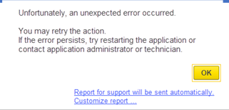
Fig. 574. Error message with configured automatic sending
Note. Tip. When you perform actions (for example, automated testing or some scheduled operations) that do not require sending configuration error reports to the error registration service, we recommend that you disable the automatic report error sending for the user on whose behalf these actions are performed.
The report will be sent after clicking OK. You can also send the report after you open the error report form. To access it, click the hyperlink. You can send the report if the error registration service is specified in the settings and this service is available from the client application.
There is a special form for the error report. There are several ways to open this form:
-
From the dialog box with the error message (click Generate error report or Error report will be sent automatically. Customize report...).
-
Using the ErrorReport.Save() method with interactive mode enabled. Interactive mode is ignored when you use it on the server side.
-
Using the ErrorReport.Send() method with interactive mode enabled. Interactive mode is ignored when you use it on the server side.
There is a special form for interactive report generation.
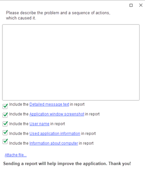
Fig. 575. Error report form
In the error report form, users can provide a free-form error description. For this, use the Please describe the problem and a sequence of actions, which caused it field. The text written in this field will be included in the errorInfo.userDescription report field. You can also specify what additional information you want to attach to the report (in the order of the checkboxes in fig. 575):
-
Detailed error text (the errorInfo.appErrorInfo property in the report).
-
Screenshots of application windows at the time of the error (the screenshot property in the report).
-
Name of the user who works in the configuration (the clientInfo.userName property in the report).
-
Information about the application used (the configInfo property in the report).
-
Some general information about the operating system on the client computer (the clientInfo.sysInfo property in the report).
-
If a crash dump is generated as a result of an error, you can specify whether it must be included in the report (the dump property in the report).
-
If required, click Attach file to attach any file to the report that can help in investigating the error (the additionalFiles property in the report).
-
To attach additional data, use 1C:Enterprise language.
31.3.6.2. report.json file format
Automatically collected information is located in the report.json file that has the following format:
-
time. Time the error was generated in JavaScript format.
-
id. Unique error report ID.
-
clientInfo. If an error is detected on the client, a structure with the client application information. If an error is detected on the server, a structure with the working process information.
-
platformType. 1C:Enterprise platform type. The value is the value of the SystemInfo.PlatformType property.
-
appVersion. Client application version (as a string) from the SystemInfo.AppVersion property.
-
appName. Client application name as the ApplicationName() method returns. On the server, you can also specify the following values:
-
BackgroundJob. For a background job.
-
HTTPServiceConnection. For an HTTP server session.
-
-
systemInfo. Structure with the operating system information.
-
osVersion. String with the operating system name (similar to the SystemInfo.OSVersion property).
-
fullRAM. Full RAM.
-
freeRAM. Free RAM.
-
processor. String with the processor description (from the SystemInfo.Processor property).
-
useragent. user-agent information of the current web browser (from the SystemInfo.UserAgentInformation property).
-
clientID. Current client application ID. The field contains the SystemInfo.ClientID property value. The client application can be a client application if the error occurs on the client, or a working process if the error occurs on the server.
-
-
-
sessionInfo. Information about the current session:
-
userName. Username.
-
dataSeparation. Separator values of the current session, similar to the Z parameter of the command line for starting the client application (see Using ).
-
platformInterfaceLanguageCode. String with the interface language code.
-
configurationInterfaceLanguageCode. String with the configuration language code for the current user.
-
localeCode. String with the session locale code (the return value of the CurrentLocaleCode() method).
-
-
infoBaseInfo. Infobase information.
- localeCode. String with the infobase locale code (the return value of the InfoBaseLocaleCode() method).
-
serverInfo. Structure that contains server cluster information.
-
platformType. 1C:Enterprise platform type. The value is the value of the SystemInfo.PlatformType property.
-
appVersion. Server cluster version (as a string) from the SystemInfo.AppVersion property.
-
dbms. Type of the DBMS the server cluster works with. For the file mode, this property value is DBEng8.
-
-
configInfo. Structure that describes the configuration information:
-
name. Short configuration name.
-
description. String with the configuration information. This string includes a full configuration name, version, address, vendor name, and delivery address. This information is displayed in the About window, in the Configuration: field.
-
version. Configuration version.
-
compatibilityMode. Configuration compatibility mode. The value is a string of the CompatibilityMode system enumeration value. The DontUse value will be replaced with the value of the version used in the accepted format.
-
hash. Configuration hash in MD5 format.
-
changeEnabled. Shows whether the configuration can be changed.
-
extentions. Extensions attached to the configuration. The extensions are listed in an array. Each element of this array is an array of two elements:
-
String with an extension name.
-
String with an extension hash.
-
-
disabledExtentions. A list of disabled configuration extensions. The extensions are listed in an array. Each element of this array is an array of two elements:
-
String with an extension name.
-
String with an extension hash.
-
-
-
errorInfo. A structure with an error description (ErrorReport.ErrorInfo):
-
userDescription. Error description text written by the user (ErrorReport.Description). Missing if the error report is generated on the server.
-
systemErrorInfo. Error information related to 1C:Enterprise.
-
clientStack. Text of the client application stack. Missing if the error report is generated on the server.
-
clientStackHash. Hash of the client application stack text in MD5 format. Missing if the error report is generated on the server.
-
serverStack. Server cluster stack text.
-
serverStackHash. Hash of the server cluster stack text in MD5 format.
-
systemCrash. Indicates that the error report is generated as a result of a client application crash.
-
-
applicationErrorInfo. Information about the error related to the application.
-
errors. Array of descriptions of all errors. The array consists of arrays. Each of the arrays consist of two elements:
-
String with an error text.
-
Array of error category strings. Array values are the ErrorCategory system enumeration values.
-
-
stack. Array with 1C:Enterprise language call stack at the time of the error. The array consists of arrays. Each of the arrays consist of three elements:
-
Module name (string).
-
Module line number (number).
-
Source text from the module line (string).
-
-
stackHash. Hash of 1C:Enterprise language stack text in MD5 format.
-
-
-
screenshot. Screenshot file. Missing if the error report is generated on the server.
- file. Screenshot file name. The file must be in an archive with the specified name.
-
additionalData. Additional data serialized to JSON. Received from the ErrorReport.AdditionalData property.
-
additionalFiles. Array of names of the files attached additionally. The files are placed in the archive with the names specified in this array. Received from the ErrorReport.AdditionalFiles property.
-
dump. Crash dump information:
-
type. Dump type. It is similar to the value of the type attribute of the dump element of the logcfg.xml file.
-
file. Dump file name. The file must be in an archive with the specified name.
-
reasonForNoDump. Reason why the dump file is not generated. Values:
-
genericFailure. Dump file creation error.
-
userRefused. User refused to generate client application dumps.
-
insufficientResources. There are not enough resources to generate dumps (only for the server cluster).
-
-
Notes about error report generation:
-
You can send abnormal termination reports only on computers running Windows.
-
Error reports, including abnormal termination reports, are sent from the same environment where the process with an error was running. It can be a client application process or a working process of a server cluster.
-
To successfully send an error report, the application that sends the error report (client application or working process of a server) must have access to the error registration service (the ErrorProcessingSettings.ErrorProcessingServiceAddress property value).
-
To successfully send an abnormal termination report, the dumper utility must have access to the error registration service (the ErrorProcessingSettings.ErrorProcessingServiceAddress property value) or the platform error registration service (https://pult.1c.com).
-
In case of abnormal termination, the error report will contain a minimum dump (type = 0) if there are not enough free resources:
-
Free RAM is less than the amount of RAM allocated to the failed process.
-
Total processor load exceeds 50%.
-
The fields in the report.json file are not required and depend on what error processing settings are specified for the user.
If you need to get the report.json file for analysis, use the ErrorReport.GetReportText() function. After you call it, you get a string, which is the contents of this file. The standard JSON reading mechanisms provided by the platform are quite suitable for reading.
See also:
-
JSON format.
-
Error registration service (see Error registration service).
-
Prohibiting the display of the error dialog box when an unrecoverable error occurs.
31.3.7. Setting up error processing
To set up error processing, use the ErrorProcessingSettings object. You can set up error processing for all users at once or for a particular user. To set up error processing for all users, use the ErrorProcessing.GetCommonSettings() and ErrorProcessing.SetCommonSettings() methods. To set up error processing for a particular user, use the ErrorProcessing.GetUserSettings() and ErrorProcessing.SetUserSettings() methods. In both cases, the error processing settings are the same. Different settings define the system behavior depending on whether an error occurs in the client application or in the server application. As a rule, the only difference is in the suffix: AtClient for an error in the client application or AtServer for an error in the server application. Hereinafter such settings will not be described separately except for some cases.
The following settings are available:
-
ErrorProcessingServiceAddress. Use it to specify the service that will be used for automatic error registration (see Error registration service).
-
MessageDisplayVariant. Use it to configure the error message appearance:
-
StandardErrorMessageForUser. In this case, the result of the ErrorProcessing.ErrorMessageForUser() method is displayed.
-
BriefErrorDescription. In this case, the result of the ErrorProcessing.BriefErrorDescription() method is displayed.
-
DetailErrorDescription. In this case, the result of the ErrorProcessing.DetailErrorDescription() method is displayed.
-
Auto. In the error processing settings, it is interpreted as follows:
-
In version 8.3.16 and earlier compatibility mode: as the BriefErrorDescription value.
-
In other cases: as the ErrorMessageForUser value.
-
-
-
IncludeUserNameInReportOnClient, IncludeUserNameInReportOnServer. Includes the current username in the error report.
-
IncludeSystemInfoInReportOnClient. Includes system information about the client computer in the error report.
-
IncludeWindowsScreenshotInReportOnClient. Includes application screenshots in the error report.
-
IncludeDetailErrorDescriptionInReportOnClient, IncludeDetailErrorDescriptionInReportOnServer. Includes a detailed error text in the error report.
-
IncludeInfobaseInformationInReportOnClient, IncludeInfobaseInformationInReportOnServer. Includes infobase information (configuration, extensions, and server) in the error report.
-
AdditionalReportInformation. Use it to specify arbitrary additional information that will be added to the report. If there is an empty string in the settings for the user, the parameter value will be received from the general settings. This string may contain the name/code of the infobase and/or area, or any other information specified by the developer.
-
SendReportOnClient. Automatically sends an application error report to the service whose address is specified in the ErrorProcessingServiceAddress property.
-
SendReportOnServer. Automatically sends an application error report to the service whose address is specified in the ErrorProcessingServiceAddress property. The setting is intended for errors that cannot be processed in the client application.
-
SendCrashReportOnClient, SendCrashReportOnServer. Automatically sends an error report when the client application is abnormally terminated to the service specified in the ErrorProcessingServiceAddress property.
-
SendCrashReportOnClientToPlatformErrorRegistrationService, SendCrashReportOnServerToPlatformErrorRegistrationService. Automatically sends an error report when the client application is abnormally terminated to 1C:Remote service: https://pult.1c.com/pult/platform/errors. To disable interaction with this service, specify the ErrorReportingMode.DontSend value in this property.
-
ErrorMessagesTexts. Use it to set error text templates.
Use the ErrorMessagesTexts property to set an error presentation for the user. This property is a collection of elements of the KeyAndValue type. The value of the ErrorCategory type is the key. The value of the ErrorMessageTexts type is the key. An object of the ErrorMessagesTexts type does not have its own constructor. You can receive it only from the error processing settings.
Use the ErrorMessagesTexts object to specify the following texts:
-
Text for a recoverable error (the RestartNotRequiredErrorText object property).
-
Text for a non-recoverable error (the RestartRequiredErrorText object property).
The message text must include user-friendly information. It may have one or more standard error presentations. The standard error presentation is an error presentation that is generated by the corresponding platform method. So you cannot change the error text generated by the platform. You can change the text that the user will see.
Consider the example: assume that for all the errors called by the Raise operator, you need to display text Unexpected error. Contact the configuration developer., and not to display the error text itself. First of all, let's decide on how the error displayed by the platform will look like if you write the code of the Raise "Error from 1C:Enterprise language"; kind in 1C:Enterprise language:
Fig. 576. Default message
If you execute the following code in 1C:Enterprise language:
Settings = ErrorProcessing.GetUserSettings();
Settings.ErrorMessagesTexts.Clear();
Text = New ErrorMessageTexts("Unexpected error. Call the developers by internal phone
1234!", "");
Settings.ErrorMessagesTexts.Insert(ErrorCategory.ExceptionRaisedFromScript, Text);
ErrorProcessing.SetUserSettings(Settings);and restart the client application, then the same exception will look as follows:
Fig. 577. New error message
However, in addition to the replacement of the whole message text, you may need a combination of the standard platform error message text and an additional text. For this, the platform provides several parameters that you can insert in the message text:
| Parameter name | Description |
|---|---|
| BriefErrorDescription | Contains the result of the ErrorProcessing.BriefErrorDescription() method. |
| DetailErrorDescription | Contains the result of the ErrorProcessing.DetailErrorDescription() method. |
| ErrorDescriptionForUser | Contains the result of the ErrorProcessing.ErrorDescriptionForUser() method. |
| StandardErrorMessageForUser | Contains the result of the ErrorProcessing.ErrorMessageForUser() method. When the system generates a message, it uses the standard platform template, and not the text that is currently set in the error processing settings. |
The parameter text is placed in the message text in square brackets []. So, if you want to add the full error text to the message, use the following code:
Settings = ErrorProcessing.GetUserSettings();
Settings.ErrorMessagesTexts.Clear();
Text = New ErrorMessageTexts("Unexpected error. Call the developers by internal phone
1234!" + Symbols.LF + "[DetailErrorDescription]", "");
Settings.ErrorMessagesTexts.Insert(ErrorCategory.ExceptionRaisedFromScript, Text);
ErrorProcessing.SetUserSettings(Settings);After you execute this code and restart the client application, the error text will look as follows:
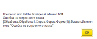
Fig. 578. Error message with platform text
You cannot always set up the behavior of the error processing system when you develop an application. For example, you may want to add contact details of a particular company's support personnel to error texts. Obviously, the application developer knows neither about your idea nor the contact details of this support. So, in the platform, you can configure error messages in 1C:Enterprise mode. To do this, use the standard Management of error processing settings function.
31.3.8. Error registration service
31.3.8.1. General information
To register error reports, publish an HTTP service that the platform will interact with when you need to send an error report. The service must implement a certain interface expected by 1C:Enterprise. You can find the interface in this section.
31.3.8.2. GetInfo method
Description
HTTP method: POST.
Ensures that 1C:Enterprise platform gets instructed on what to do with an error in this configuration.
Parameters
Request bodyinput
Contains a request in JSON format. Error report values are passed to the request. The correspondence of request properties and error report properties is shown in the following table:
| Request field | Error report field |
|---|---|
| appName | clientInfo.appName |
| appStackHash | errorInfo.applicationErrorInfo.stackHash |
| appVersion | clientInfo.appVersion |
| clientID | clientInfo.clientID |
| clientStackHash | errorInfo.systemErrorInfo.clientStackHash |
| configHash | configInfo.hash |
| configName | configInfo.name |
| configurationInterfaceLanguageCode | sessionInfo.configurationInterfaceLanguageCode |
| configVersion | configInfo.version |
| errorCategories | Array that contains unique error categories from the errorInfo.errors list |
| platformInterfaceLanguageCode | sessionInfo.platformInterfaceLanguageCode |
| platformType | clientInfo.platformType |
| reportID | id |
| serverStackHash | errorInfo.systemErrorInfo.serverStackHash |
| systemCrash | errorInfo.systemErrorInfo.systemCrash |
Return value
Request bodyoutput
Contains a response in JSON format with actions to be executed by 1C:Enterprise:
- needSendReport. The error must be sent to the registration service.
Boolean.
- userMessage. Text that will be shown to the user as additional error information. We recommend that you return the text in a user-friendly language. You can receive localization information from a request received in the getInfo method.
If you want the user to send a report on a specific error to the error registration service, use this property to show the user a recommendation that motivates them to send an error report.
String.
- dumpType. Dump type to be attached to the error report. It is similar to the value of the type attribute of thedump item of the logcfg.xml file. The client application will analyze this field if the response is generated for a request related to a client application crash (the systemCrash request field is set to true). If the response does not contain this field, the dump file will not be sent.
Number.
31.3.8.3. PushReport method
Description
HTTP method: POST.
An error report is being sent to the error registration service.
Parameters
Request bodyinput
The body contains a report file for support as an archive.
Return value
No.
31.4. Performance snapshot
31.4.1. General information
Performance snapshot can be used to evaluate performance of the entire configuration or its part that is running within a debug item of any type. You may measure the use frequency for specific code sections and speed of their execution, specify the code that was executed on the server or on the client, and indicate the code lines that have initiated server calls. If there are several methods to solve a problem, you may implement them all, and then choose the fastest one.
Please remember that the comparison should be made under the same conditions. For example, if during the task performance using one of the compared methods, the computer processor was performing some other task, this may affect the accuracy of the comparison. There are other, less obvious reasons why the measurement conditions are different. So, when you compare two methods with similar performance, it is recommended to perform several snapshots for each method to estimate and average the random scatter.
Use the Debug – Performance snapshot command to measure performance. When you select this command again, the measurement stops and the measurement results window opens. Enabling and disabling the performance measuring affect all debug items currently attached to the debugger.
31.4.2. Available action options
If you need to measure the configuration performance, including the system startup section, you must first run the Debug – Performance snapshot command, and then start 1C:Enterprise. The time elapsed between the start of measurement and the start of system operation is not considered in the measurement results.
If you do not want to include the startup section in the snapshot, first launch 1C:Enterprise and prepare it for execution of the required section. Then switch to the Designer and start the performance snapshot.
If you need to include in the measurement the section that is executed at the 1C:Enterprise shut down, then regardless of whether Option 1 or 2 was used to start the snapshot, you should shut down the program and then switch to the Designer mode. In this case, you do not need to stop the measuring manually. Once the measurement results are ready, they are displayed on the screen.
If no measurement is required for the section executed at the 1C:Enterprise shut down, then the performance snapshot should be stopped to view the measurement results. For example, to analyze the procedure for any document, you need to start the program, open the document and fill it, switch to the Designer mode, start the performance snapshot, switch to the 1C:Enterprise mode, post the document, switch to the Designer mode and finish the performance snapshot.
31.4.3. Measurement results
Measurement results are references to specific module lines that specify the frequency and length of the execution. They are displayed as a table field with the following columns:
-
Module. Contains the module name.
-
Line number. Module line number.
-
String. Module line text.
-
Usage count. Number of calls of this string during the measurement.
-
Time (net). Total runtime (in seconds) for this string during the measurement.
-
%(Time) (net). Percentage of the total runtime for this line to the total snapshot time (total snapshot time equals the sum of all time intervals of executing the configuration code). In this case, 100% is the execution of code on the client.
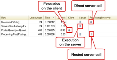
Fig. 579. Performance snapshot icons
-
Client. The icon (numbered as 1 in fig. 579) marks the code lines running on the client.
-
Standalone server. The icon (numbered as 3 in fig. 579) marks the code lines running on the standalone server of the mobile client with standalone mode. The column associated with the standalone server and the Standalone server filter checkbox will be available only if you are debugging a mobile client with standalone mode enabled.
-
Server. The icon (numbered as 3 in fig. 579) marks the code lines running on the server.
-
Processing by server. The icons mark the code lines that initiate a server call:
-
The server call at the platform level, or directly called procedures/functions executed on the server (numbered as 2 in fig. 579).
-
The local call to the procedure/function executed on the client, within which the server was called at the platform level, or directly called procedures/functions executed on the server (numbered as 4 in fig. 579).
-
Runtime for each string in the performance snapshot is made up of runtime of string operators ("net time") and call time of the procedure (function), if there are any in the string. Select the Track execution time for procedures and functions checkbox to choose whether to show the full time (as a sum of the call time and the net time) or the net time.
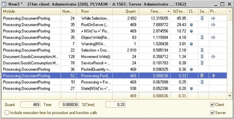
Fig. 580. Measurement results
If a string contains at least one procedure (function) call, the runtime includes runtime of string operators and call time of the procedure (function).
If the checkbox is selected, the procedure (function) call time is included in the total execution time.
If this checkbox is cleared, the measurement result includes only the code line execution time, but not the execution time of the procedure (function) that is called in this line. In this case, the total runtime of this line (in the Time column) does not reflect the actual time spent by the system to process this line. Please remember that execution of called procedure (function) may be time-consuming, and in this case this time is not included in the result ("net time"). The checkbox is selected by default and its state is saved between the sessions. If the state change, the time columns headers will change.
In the lower right corner of the form with the measurement results (see fig. 580), you can select checkboxes to display the performance measurement results:
-
Select the Client checkbox to display the results of code execution measurement on the client.
-
Select the Standalone server checkbox to display the results of code execution measurement on the standalone server of the mobile client with standalone mode.
-
Select the Server checkbox to display the results of code execution measurement on the server.
-
Select or clear the checkboxes to display the desired combination of performance measurement results.
The checkboxes are shown if server infobase is being debugged. The checkboxes are available if you are debugging a server debug item.
If there are several open windows with the performance measurement results, when you hover the mouse pointer over the results column, you can see a tooltip with the URL of the file which data is shown in this column.
If you double-click in the column with the performance measurement results in the module editor, you will move to the corresponding line in the file with the performance measurement results.
In addition to the special window, the measurement results can also be viewed in the module source code window. If a performance snapshot window is open in the debugger, a column appears in the module windows showing the number of calls for the current string and the percentage of its work to the total time.
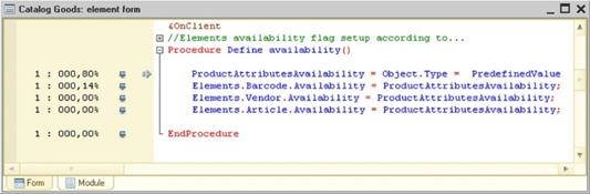
Fig. 581. Measurement results in module text
The icons show the code execution on the client or server, as well as server calls (similarly to the measurement results window), description of icons (see fig. 579).
Double-click a line in the measurement results window to switch to the corresponding line in module window.
If several snapshots are opened at the same time, the module text windows contain the corresponding number of columns.
Closing the measurement results window removes columns with the number of calls and a percentage of working time from the modules.
31.4.4. Sorting measurement results
Measurement results can be sorted by any column in the report.
You can sort by clicking on the header of one of the columns. Click the Module or Line headers to sort by line number, Usage count by the number of line calls, Time or %(Time) by operating time. If the code execution performance was measured on the client and on any server, you can also sort measurement results by these columns.
31.4.5. Selective sum-up of measurement results
Cumulative performance or combined characteristic may be useful for analyzing the measurement results. If several lines are selected in the results window, their summaries (total number of calls, total working time in seconds and percentages) are displayed at the bottom of the window.
Select the Track execution time for procedures and functions checkbox to select one of two methods for roughly tracking nesting levels when summarizing. If this module contains both a line that calls a certain procedure and text lines of the procedure, do not select both as it will result in double counting of the execution time. If you still need to select them (for example, when it would take too much effort to track these items), you clear this checkbox to avoid duplicate counting. If all the called procedures are external to the module, it is better to select this checkbox. Then the total runtime includes the runtime of these procedures providing more accurate results.
31.4.6. Performance snapshot for client/server infobases
When the performance snapshot is produced, the results for the 1C:Enterprise language code executed for the same connection number on both client and server are summarized. In this case, the results indicate which code lines were run on the client and which ones on the server. They also show which lines called procedures or functions executed on the server as well as platform system calls (for example, the Execute operator for a query, or database object record operator) on the server.
When you view the results, you can specify what you want to display in the measurement: measurement for the client, measurement for the server, or measurement for the client and server together. The mode is selected using checkboxes in the lower right corner of the window with the performance snapshot results.
For server calls, the time to make the server call on the server is taken into account. The entire procedure can be compared to execution time of nested procedure and function calls for a client application.
31.4.7. Saving results
Measurement results can be saved in a file using the File – Save and File – Save as commands. Select directory and specify file name in a standard save dialog box. The result file has an extension *.pff.
You can open a file with the measurement using the File – Open file command. To filter measurement files, use the Performance Measurement (*.pff) filter.
31.5. Server call delay simulation
You can use the tool to simulate the application operation under the conditions of significant time delays arising during interaction with the server.
Note. Note. The tool can be enabled only in the thin client or in the thick client managed application mode.
The tool provides simulation of time delays arising in the following cases:
-
Server call delay: specified in seconds for each server call.
-
Delay in sending data to the server: specified in seconds per 1 KB (1024 bytes) of data sent to the server.
-
Delay in receiving data from the server: specified in seconds per 1 KB (1024 bytes) of data received from the server.
You can enable this functionality in Designer settings (see General parameters) as well as using the command line key /SimulateServerCallDelay [-CallXXXX] [-SendYYYY] [-ReceiveZZZZ], where:
-
Call. Parameter indicating the server call delay in seconds. It is equal to 1.45 seconds unless other value is specified.
-
Send. Parameter indicating the delay in seconds per 1 Kb of data sent to the server. It is equal to 0.45 seconds unless other value is specified.
-
Receive. Parameter indicating the delay in seconds per 1 Kb of data received from the server. It is equal to 0.15 seconds unless other value is specified.
Example:
/SimulateServerCallDelay Call2.1
Send1.3 Receive1.2Note. Note. The maximum delay value can be set to 9.99 seconds. 0 means that this delay does not apply.
Server call delay simulation can also be enabled in the 1C:Enterprise mode. To do this, use the Tools – Options dialog box. Configuration of the server call delay simulation in the 1C:Enterprise mode is only valid in the current session and is not saved.
31.6. Server call history
You can use this functionality to debug the client/server system and assess the amount of data transferred between the client and the server.
You can enable the mode in Designer settings (see Additional parameters) or by using the /DisplayPerformance command line key. You can also enable displaying of performance indicators in 1C:Enterprise mode by selecting the Show performance indicators checkbox in the Tools – Options dialog box. The functionality is disabled by default.
If the mode is enabled, 1C:Enterprise displays performance indicators in the performance indicator panel at the bottom of the main application window.
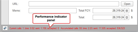
Fig. 582. Performance indicators panel
If the delay simulation mode is enabled when a server is called, the picture in the window showing server calls will look like this:
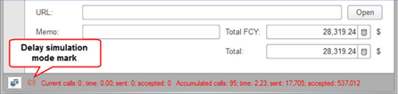
Fig. 583. Server calls in slow connection simulation mode
If you have not yet opened or have already closed the main application window, but the application code is running, then the performance indicators window looks like this:

Fig. 584. Server calls
If the server delay simulation mode is enabled, the performance indicators window looks like this:

Fig. 585. Server call delay simulation
When you change the data displayed in the server call window, it is displayed in red.
By default, the window consists of the Current calls and Accumulated calls counters:
-
Current calls shows the state of server calls since the mechanism was started or since the last user action, after which there were no other user actions for 0.2 seconds.
-
Accumulated calls shows the state of server calls since the mechanism was started or was last forced to be reset from the context menu.
Performance indicators settings can be configured using the Performance indicator settings dialog box. You can open this dialog box by clicking the button in the performance indicator bar and selecting Settings in the menu.
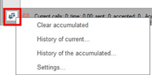
Fig. 586. Settings menu
You can specify the following parameters in the settings dialog box:
-
Periodicity group. Indicates the period for displaying the counter values.
-
Indicators group. Defines which indicators are to be displayed in counters.
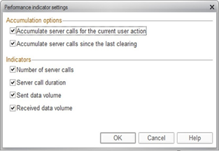
Fig. 587. Performance indicators settings
The context menu of this window contains the following commands:
-
Clear accumulated. Clears the accumulated calls counter.
-
History of current. Opens the history for the current calls counter.
-
History of accumulated. Opens the history for the accumulated calls counter.
The settings are common for all users and all infobases of the computer. Setup of server calls window display in the 1C:Enterprise mode is only valid in the current session and is not preserved.
Keep in mind the following functionality specifics:
-
When working in the file mode (if directly connected to the infobase), the amount of data is displayed without compression, since compression is not applied in this case.
-
When working in client/server or the file mode with a connection through a web server using the SDC traffic compression mode, the indicator values may be affected by the sequence of actions, since compression is performed using the previous transmitted data.
In the web client, this functionality has several specifics:
-
Only synchronous calls are taken into account.
-
The amount of data transferred is displayed in characters, not bytes. Measurement results can be used to compare various call options in the web client, but it is not recommended to use the results to compare the amount of transferred data for different client types.
-
Performance indicators are not displayed until the main application window opens, while the values of the indicators accumulate. After the main application window is displayed, you can see the results of web client startup.
-
The window with indicators has a larger size than on other clients, and is not displayed over the other windows.
31.7. Automated testing of applications
31.7.1. General information
Automated testing is a simulation of interactive user actions and verification of the results of these actions.
Note. Note. Automated testing is only supported for managed applications.
The automated testing scenario is a program powered by 1C:Enterprise language. The scenario describes a sequence of actions and validation of their results. There are special objects in the 1C:Enterprise language that can be used to simulate interactive actions in the application being tested and provide access to the logical model of the client application interface and managed form items. You can apply one test scenario to any client application under test.
Two systems are involved in the testing: the test manager and the test client. The testing manager provides:
-
Establish a connection with the test client to run a test scenario (test connection).
-
Execute the test scenario.
-
Evaluation of test results (if required).
The testing client provides:
-
Execute test scenario commands passed from the test manager.
-
Transfer of data required for test results evaluation to the testing manager.
The test manager can be a thick or thin client. A test client can be a thick client, a thin client, a web client, a mobile client, or an application on a mobile platform. One test manager can be connected to multiple test clients at the same time. One test client can be connected to one test manager. For interaction between the test manager and the test client, a direct TCP/IP connection is used via a specific port. This port must be "open". The testing manager and the testing client, that is a web client, interact using the 1C:Enterprise server (for client/server mode of tested application) or a web server (for file mode). Always use a web server for the interaction of the test manager and the test client that is a mobile client or an application on a mobile platform. Testing does not require any changes to the tested application.
The automated testing mechanism does not allow receiving and managing information about the structure of window objects for the system windows of a web browser. So, it is necessary to avoid actions in the web client that could result in such windows, since this will make it impossible to automatically continue the test. An example of such action is an attempt to enter text in an input field with automatic filling. In this case, a built-in dialog box will be displayed in the thin client, and a system dialog box will be displayed in the web client. So, when planning a test, keep this feature in mind and create the test accordingly.
The test scenario can be stored either in the application under test or in a separate application. The scheme of interaction between the test manager and the test client does not change.
Note that the test manager and the executing test scenario do not have direct access to the application under test. The test scenario has access to all features of the application where the scenario is running (test manager) and access to the logical model of the interface and forms of the application under test (test client).
Running a client application in testing client mode does not affect performance and other client application settings, however, it allows any test manager to connect to it, knowing the name (or IP address) of the computer and the port, through which the interaction takes place.
The application also can be used to save interactive user actions to an .xml format file. You will be able to use this file later for automated testing. For such recording, use a special startup mode of the application under test. Managing the recording of interactive actions is also available from 1C:Enterprise language.
31.7.2. Testing system start-up
31.7.2.1. General information
To run the test scenario, start both the test manager and the test client. Startup order is arbitrary. It is important that by the time you start the test scenario, the test client is running and available at the address used to connect the test manager.
Starting is possible both from the command line (this method will be discussed below) and from Designer. The application that you start from Designer can be either a test manager or a test client, depending on the settings specified in the Designer settings dialog box (see Setting Designer parameters). The mobile client can only act as the test client.
31.7.2.2. Testing client start-up
To start the test client, use the TestClient command of the command line for starting the client application. You can also specify the number of the TCP port to be used for testing manager and testing client interactions. For this, use theTPort parameter of the TestClient command. If there is no specified value for this parameter, 1538 is used. Specify this parameter if you have multiple test clients running on a single computer.
Thus, the startup line of the client application that should act as a testing client, is as follows:
1cv8c
ENTERPRISE /IBName "Test Application" /TestClient -Tport 1843In this example, the thin client (1cv8c) will be a test client for the Test Application infobase. It will use the 1843 TCP port to interact with the test manager.
If the client application is running as a test client, Test client will be displayed in the title of the main application window. Similar text will also be displayed in the About window. In 1C:Enterprise language, you can check that a client application is running as a test client using the CurrentSessionIsTested() global context method. If the method returns True, the client application is running as a test client and is ready to execute the test manager commands.
To connect to a test client that is a thin or thick client, you need two parameters: the IP address or computer name where the test client is running, and the TCP port number to be used for interaction.
If you start a web client or a mobile client, the situation is slightly more complicated. In addition to the TestClient command, specify another command-line parameter: TestClientID=<ID>. It contains a UUID of the client application under test. To unambiguously specify the test client, in the case of a web or mobile client, you need the following parameters:
-
Address of the web server where the tested application is deployed. You do not have to know the infobase address.
-
ID of a specific instance of the application under test running on the web/mobile client.
-
TCP port number to be used by the web server to transfer data between the manager and the testing client.
Since a single web server can serve multiple infobases and multiple connections to one infobase, including for testing, instruct the web server which TCP ports must be used to interact with the test manager. To do this, use the testcfg.xml file located in 1C:Enterprise settings directory that serves the test client published on the web server.
If the test client is a mobile application created for the mobile platform, the TULR parameter of the TestClient command is added to the command line for starting the test client. The TURL parameter value indicates the publication URL of an infobase running in test manager mode. Specify the TestClientID parameter for a mobile application if several test clients are running simultaneously (similar to the web client).
You can test the mobile client using automated testing tools on your automated testing tools. To do this, follow the steps:
-
Start the test manager on your personal computer.
-
Start the test client on the mobile client running under Android in the emulator.
-
Run the test client in the mobile client under the test manager running on your personal computer.
This will require a code in 1C:Enterprise language that will start the test client in the emulator. Add this code to a configuration that creates the required infrastructure for testing and starting test scenarios. To start the mobile client in test client mode, use the following code:
PathToAndroidSDK = "<Path to the root directory of Android SDK>";
ApplicationID = "<ID of the application to start>";
PublicationURL = "http://host/test";
Command = PathToAndroidSDK + "/platform-tools/adb.exe shell am broadcast –-user
current –n " + ApplicationID + "/com.e1c.mobile.Starter –a
com.e1c.mobile.START_CMD –es cmd '/WS "+ PublicationURL + "
/TestClient'";
Await
RunAppAsync(Command);See also:
-
Client application startup command line.
-
testcfg.xml file.
31.7.2.3. Testing manager start-up
To run the test scenario, start the client application in test manager mode. Use the TestManager command-line key to run the client application. You cannot use the web client as a test manager.
Thus, the startup line of the client application that should act as a testing client, is as follows:
1cv8c ENTERPRISE /IBName
"Test Manager" /TestManagerIf the client application is started as a test manager, the Test manager text will be displayed in the title of the main application window. Similar text will also be displayed in the About window.
31.7.2.4. Starting in interactive action log record mode
The client application is started in the mode that allows you to record interactive actions, either using theUILogRecorder command line key or using the appropriate command of Designer menu: Service – Start to record the user actions log.
You can also specify the IP port number to be used by the testing manager to control recording of the interactive action log. For this, use the TPort parameter of the UILogRecorder command. If there is no specified value for this parameter, 1538 is used. You can also select the location where the system will save the log file. To do this, use the File parameter of the UILogRecorder command. If this parameter is not specified, after the file is recorded, the client application opens a text document window containing the saved log.
Thus, the startup line of the client application, which should allow to generate a log of interactive actions, looks as follows:
1cv8c
ENTERPRISE /IBName "Test Manager" /UILogRecorderWith this launch, an appropriate command bar is added to the upper right corner of the main window of the client application that controls the journal entry.
Fig. 588. Testing command bar
Numbers refer to the following:
- The button to start recording the user action log.
If you click the only available button on this panel, the recording of user actions will begin. The panel will also change its type (all buttons will become available).
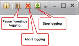
Fig. 589. Testing command bar during recording
Numbers refer to the following:
-
The button to temporarily stop/continue recording the user action log.
-
The button to stop recording the user action log. The action log written up to the time you clicked the button will be lost.
-
Finish recoding user actions. After you finish the recording, the list of actions will be written to a file (if the File parameter is specified) or a text document window with the list of actions will be opened.
If a mobile client acts as a client application, note the following features:
-
The developer's mobile client always runs in user action log record mode. To manage the recoding of user actions, click Service and settings – Log user actions.
-
For the UILogRecorder command specified in the command line for starting the mobile client, only the File parameter is available. The file with the recorded scenario will be on the device where it was recorded. The TPort parameter is not used in the mobile client.
31.7.3. Capabilities
In terms of the test scenario, the application under test is a set of objects that is used to simulate interactive actions in the application under test and provides access to the logical model of the client application interface and managed form items:
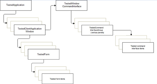
Fig. 590. The scheme of the tested application
If any object of the application under test has subordinate objects, you can:
-
Get a list of the objects subordinate to the current one using the GetChildObjects() method.
-
Get an object that is the parent of the current one using the GetParent() method.
-
Find one or more objects with the specified type, name, and title. To do this, use the GetObject(), FindObject(), and FindObjects() methods.
When operating with a collection of objects that are acquired using the GetChildObjects() method, it is recommended to use the FindObject() or FindObjects() methods instead of referring to a collection item by index.
Many test objects allow you to perform the same-type actions, for example:
-
Activate the object. Activate() method.
-
Get the item availability. CurrentEnable() method.
-
Be able to change data in an item. CurrentReadOnly() method.
The presented objects will be discussed in detail in the section below.
TestedApplication
Provides the following capabilities:
-
Connect to the application under test.
-
Disconnect from the application under test.
-
Get an active window.
-
Get a list of windows of the application under test.
-
Get the current error information.
-
Get the home page of the application under test.
-
Find an object with the specified parameters in the hierarchy of subordinate objects.
-
Wait until an object with the specified parameters appears on the screen.
-
Get and clear the accumulated performance indicators of the application under test.
-
Get the command interface of the application under test.
-
Simulate operations with the file selection dialog box.
-
Manage logging of interactive user actions in the application under test.
-
Get and set the maximum time of any test client operation.
The TestedApplication object can expect the occurrence of an event in the application under test without eternal loops. For this, use the WaitForCondition() method. Once per second, the method calls a function that checks the expected condition. If the required condition has come, the WaitForCondition() method completes ahead of schedule and returns True. If the required condition has not come after some time (which is a parameter of the WaitForCondition() method), the WaitForCondition() method returns False.
TestedClientApplicationWindow
Describes the client application window and provides methods for window management:
-
Get a collection of subordinate objects for the window.
-
Search for an object with specified parameters in the subordinate object hierarchy for the client application window.
-
Determine that this window under test describes the home page (desktop).
-
Get the command interface of the client application under test.
-
Operate with user messages.
-
Close the form under test.
-
Get the form URL.
-
Run a command using a navigation link.
TestedWindowCommandInterface
Describes the command interface for the application form under test. It has several subordinate objects TestedCommandInterfaceGroup objects:
-
Sections panel (if it contains sections).
-
Navigation panel (except for Taxi interface).
-
Actions panel (except for Taxi interface).
-
Current section functions panel.
-
Open items panel.
-
Toolbar.
-
Favorites panel.
-
History panel.
-
Functions menu (except for Forms in separate windows interface).
For auxiliary windows, the command interface of the form only has the form navigation panel. When opening forms in tabs, theTestedWindowCommandInterface object, related to the main application window, does not allow getting information about subordinate groups and items of the command interface.
TestedCommandInterfaceGroup
This object describes the command interface group and allows you to get a collection of subordinate objects for the group as well as search for an object with specified parameters in the subordinate items hierarchy.
TestedCommandInterfaceGroup can consist of two types of items:
-
TestedCommandInterfaceGroup.
-
TestedCommandInterfaceButton.
TestedCommandInterfaceButton
Describes a command of the command interface and can be used to simulate a button click.
TestedForm
Describes the form of the application under test and provides methods for form management:
-
Get a collection of subordinate objects for the form.
-
Find an object with specified parameters in the subordinate object hierarchy of the form.
-
Get the current active item of the form.
-
Get the default button.
-
Get the modified flag.
-
Get the command bar of the form.
-
Select from the list or from the menu, get a choice list presentation.
-
Change the current form item to the next/previous item based on the form item tab order (the item list in the managed form editor).
TestedFormField
This object describes the form input field and provides methods for managing this form item:
-
Get a collection of subordinate objects of the form field.
-
Find an object with specified parameters in the subordinate object hierarchy for the form field.
-
Define the form item appearance.
-
Can be used to simulate interactive actions for the following types of managed form fields:
-
Input field
-
Label field
-
Picture field
-
Radio button field
-
Checkbox field
-
Indicator field
-
Slider field
-
Calendar field
-
Text document field
-
Formatted document field
-
Spreadsheet document field.
-
HTML document field.
-
-
No simulation of interactive actions is available for the following types of managed form fields:
-
Geographical schema field
-
Chart fields (of any type)
-
Graphical schema fields
-
-
If the object is associated with an input field, the following options are provided:
-
Get the text editable in the input field.
-
Simulate clicking the Clear button.
-
Simulate clicking the Select button.
-
Simulate clicking the Open button.
-
Check the display of the input field header.
-
Simulate opening the selection list.
-
Simulate selecting a row from the selection list.
-
Simulate creating a new item from the selection list.
-
Cancel editing the line in the input field.
-
Simulate pressing the increment/decrement buttons.
-
Simulate clicking a hyperlink located in a formatted string displayed by the form field.
-
Get the displayed text for some input field kinds.
-
For dropdown list:
-
Open the list.
-
Wait for list generation.
-
Close the list.
-
Make a selection from the dropdown list.
-
-
-
If the object is associated with a checkbox field, you can:
- Simulate toggling.
-
If the object is associated with a radio button field, the following options are provided:
-
Stimulate selecting a radio button value.
-
Get a presentation of all values of the radio button selection list.
-
-
If the object is associated with a calendar field, the following options are provided:
-
Simulate setting the selected date.
-
Simulate selecting the date.
-
Simulate forward and backward operations (by month and year).
-
-
If the object is associated with a spreadsheet document field, the following options are provided:
-
Get the address of the current area.
-
Get the text of the current area.
-
Simulate the start of editing the current area.
-
Simulate the end of editing the current area.
-
Simulate a selection from the spreadsheet document drill-down menu.
-
Getting the current editing mode for a spreadsheet document.
-
-
If the object is associated with an HTML document input field, you can:
-
Set the displayed HTML document.
-
Get the document displayed in the HTML document field.
-
Simulate clicking a hyperlink located in an HTML document.
-
-
If the object is associated with a spreadsheet document input field, HTML document, text document, or formatted document, you cave save a document to a file.
TestedFormTable
Describes the form table and provides methods for managing this form item:
-
Get the active table item.
-
Get the table cell text.
-
Navigate through table rows and columns.
-
Select a row.
-
Add, remove, or copy a row.
-
Get the current table edit mode.
-
Change the deletion mark for a row.
-
Select and receive selected rows.
-
Change the table sort order.
-
Navigate through hierarchical list levels.
-
Collapse or expand a node for hierarchical lists.
-
Check the state of the hierarchical list node (whether it is collapsed or expanded) and expandability of the current row in the hierarchical list.
In the mobile client, to edit a table row, use an edit form. If you edit a form table row while testing, the edit form is opened automatically when you start editing the row. When you finish editing the row, the edit form is closed automatically.
TestedFormButton
Describes the form button and allows you to stimulate clicking it and check the mark state.
TestedFormGroup
Describes a group of form items and provides methods for the group management.
-
Expand group.
-
Collapse group.
-
Allows you to check whether the group is collapsed (for a collapsible or popup group).
-
Get the current group page.
In the mobile client, when you activate an item inside an automatically collapsible group, such group is expanded automatically.
TestedFormDecoration
Describes the form decoration and allows you to stimulate clicking a hyperlink (including the one placed in a formatted string) or a picture.
TestedFormItemAddition
You can get objects of this type as subordinate objects for items of the TestedFormTable type form. Use the form item add-on under test to access the following form item add-ons:
-
Search string display.
-
View status display.
-
Search management display.
Use this object to perform the following actions with a form item add-on (some actions depend on the add-on kind):
-
Get the add-on kind.
-
Get the tooltip text.
-
Get and set visibility.
-
Get the view state.
-
Get the item availability.
-
Get the data presentation displayed by the item.
-
If the add-on kind is a search string, you can:
-
Activate the item.
-
Perform interactive actions with the item (enter text, get edit text, cancel editing, or clear).
-
-
If the add-on kind is a view state, you can:
-
Get texts of items displayed by the add-on.
-
Click any item of the view state.
-
Delete the view state item.
-
31.7.4. Sample testing scenario
Here is a simple example of creating a new item in the Goods catalog in a configuration. Make sure the main form of the item contains a field with the Name header and the Save and close button.
// Connect to the application under test
TestedApplication = New TestedApplication("localhost");
TestedApplication.Connect();
// Find main window
MainTestedApplicaitonWindow = TestedApplication.FindObject(Type("TestedClientApplicationWindow"));
MainTestedApplicaitonWindow.Activate();
// Run a command of item creation in the Goods Catalog
MainTestedApplicaitonWindow.ExecuteCommand("e1cib/command/Catalog.Goods.Create");
TestedApplication.WaitForObjectDisplayed(Type("TestedForm"), "Good*");
TestedForm = TestedApplication.FindObject(Type("TestedForm"), "Good*");
TestedForm.Activate();
// Set a name for a new item
FormElement = TestedForm.FindObject(Type("TestedFormField"). "Name");
FormElement.Activate();
FormElement.InputText("New item");
// Save item
FormElement = TestedForm.FindObject(Type("TestedFormButton"), "Save and
close");
FormElement.Click();31.7.5. Service features
31.7.5.1. User action log entry
You can run a client application in the mode that supports logging interactive actions. You can later save this log to a file. For the mode details, see Starting in interactive action log record mode.
31.7.5.2. Converting the user action log into an automated testing scenario
You can convert a saved user action log into the 1C:Enterprise language code to use afterwards.
Using this tool, you can do the following:
-
Convert both a log file (for example, a file saved earlier) and the text entered manually (in the log format).
-
Specify the 1C:Enterprise language option for the resulting code written in 1C:Enterprise language.
-
Add code to implement the connection to the test client.
-
Specify whether long sequences of actions should be split into procedures, each working with a single test application window.
The resulting code can be used, for example, for multiple automatic execution of the converted set of actions.
Chapter 32. Add-ins
32.1. General information
1C:Enterprise is an extensible application. To extend its functionality, use add-ins.
The application uses two technologies for creating add-ins:
-
Using Native API.
-
Using COM technology.
This allows you to create add-ins for:
-
Linux, macOS, and Windows operating systems.
-
Web clients running in Google Chrome, Microsoft Internet Explorer, Mozilla Firefox, and Safari web browsers.
-
Mobile applications running on Android, iOS, and Windows mobile operating systems.
Add-ins designed for a web client or mobile application environment must be packed in a ZIP archive with an appropriate structure. This file can also be used on the 1C:Enterprise server and in other clients.
When you attach an add-in, you can specify its attachment type in the AttachmentType parameter of the AttachAddIn() method. The parameter specifies how the add-in will be loaded and used. This parameter can take values of the AddInAttachmentType (system enumeration) type. The system supports the following attachment types:
-
NotIsolated. Add-in is loaded and executed in the same operating system process where 1C:Enterprise language code is executed. In this case, abnormal termination of the add-in will result in abnormal termination of the entire process that uses this add-in. Abnormal termination of a process using an add-in means that all sessions served by the terminated process will also be terminated. In the documentation, this attachment mode will be referred to as non-isolated.
-
Isolated. Add-in is loaded into a separate operating system process that is not related to the process where 1C:Enterprise language code is executed. Such process will be further referred to as a "host process". If an add-in running in the host process is abnormally terminated, the process running 1C:Enterprise language code (client session) will not be affected. Only the host process will be abnormally terminated. In the documentation, this attachment mode will be referred to as isolated.
If the add-in is attached in isolated mode, a host process is created. If you cannot create the host process (for example, because you have no rights to create a separate process), the add-in will be attached in non-isolated mode. So, the system performance will stay the same. However, if the add-in does not support non-isolated attachment, it cannot be attached. Hence, the system will not operate smoothly.
To run an add-in in the host process, this add-in must be created or customized considering some of the add-in technology features specified on the ITS portal. Note that when you attach an add-in and specify only the object ID (the AttachAddIn() method with one parameter), the add-in is always attached in non-isolated mode.
Successful add-in attachment normally depends on two factors: attachment types the add-in supports and, if no attachment type is specified, the current configuration compatibility mode:
-
Attachment type in the AttachAddIn() method is not specified:
-
If version 8.3.20 or earlier compatibility mode is enabled in the configuration, the add-in is attached in non-isolated mode.
-
Otherwise, the add-in is attached:
-
On the client: in non-isolated mode.
-
On the server: in isolated mode.
-
-
-
If the add-in supports the attachment type, it is attached. Otherwise, an exception is thrown. For example, version 8.3.19 compatibility mode is enabled in the configuration, the add-in supports only the isolated attachment mode, and the AttachAddIn() method is called without specifying the attachment type. In this case, an exception is thrown and the add-in is not attached.
To correctly process possible abnormal terminations of add-ins running in host processes, perform a number of actions. To process abnormal add-in terminations, use the following event handlers:
-
AddInDetachmentOnErrorProcessing() in the application module.
-
AddInDetachmentOnError() in the form module.
Control is passed to these handlers when an add-in is abnormally terminated and after 1C:Enterprise language code is executed. In the event handler, you can identify the terminated add-in, as well as reattach and initialize it. Note that if an isolated add-in is attached and initialized on the server, its abnormal termination cannot be processed on the server. It can be processed only on the client by the event handlers described above.
When an add-in that is packed in a ZIP archive is used, to specify the add-in parameters (name of the file to be installed, type, architecture and web browser to be used), a specific manifest file generated by the add-in developer is used. Add-ins obtained from a configuration or an infobase are saved when received and used upon subsequent connection (using the InstallAddIn(), AttachAddIn(), or AttachAddInAsync() method) without re-obtaining (the add-in used on the server is only saved for the working process lifetime of the server). The add-in is cached. Data changes will be tracked for add-ins that were attached from data in the infobase. Data is checked when you attach the add-in but not more than every second. If data was changed since the last add-in attachment, add-in cache will be cleared for this add-in. As a result, the add-in will be extracted from data again upon the next add-in attachment. For metadata objects that do not have a record version, the cache will be cleared when data is accessed but no more than every second.
When operating add-ins created using Native API, follow the procedure:
-
The interface implements a command that installs the add-in on the user's computer (the InstallAddIn() global context method). This operation is required in thin and web clients.
-
The add-in is attached using the AttachAddIn() method. Keep in mind that an attempt to attach a non-installed add-in causes an error.
-
Create an add-in object using the wizard (the New() statement) where a string ID generated by certain rules acts as a name.
-
An attached add-in is used in compliance with the provided API.
-
To process an abnormal termination of an isolated add-in, it is recommended that you attach a handler that is called upon abnormal add-in termination.
Note. Tip. Do not combine codes for add-in installation and attachment. Installation is considered a one-time event and re-installation will throw an interactive exception.
Note. Note. Add-ins that are designed using COM technology with theLoadAddIn() and AttachAddIn() methods are attached and add-in objects are registered "for the user". If "for user" registration fails, an attempt is made to perform "for computer" registration.
If an add-in is attached using theAttachAddIn() method, the parameter in the New() operator (of the name of the type being created) is generated from the following parts:
-
Text Addin..
-
Name specified as the Name parameter of the AttachAddIn() method.
-
Name of the object implemented in the add-in.
If the Timer object is implemented in the add-in and the add-in is attached with the AttachAddIn(URL, "MyName"); code line, specify the New("AddIn.MyName.Timer") ID to create an object from the add-in.
See also:
- For more add-in technology details, see http://its.1c.ru/db/metod8dev#content:3221:hdoc (in Russian)
32.2. Thin and thick client specifics
When operating in thick and thin clients, you can use add-ins developed with COM technologies as well as add-ins developed with Native API technologies (as separated files stored on hard drive or appropriate ZIP archives).
To update an add-in, re-install the add-in using the InstallAddIn() method.
Add-ins are installed in the %APPDATA%/1C/1Cv8/ExtCompT directory. Add-in installation directory is not treated as cache and is not cleared when 1C:Enterprise is called using the /ClearCache command line key. Using the InstallAddIn() method is required in thin client.
32.3. Web client specifics
In a web client, you can use add-ins developed with Native API or COM technology and add-ins packed in an appropriate ZIP archive. Add-ins developed with COM technology can be used only if the web client runs Windows. When installing the add-in file, the user permission for extension installation is asked. When you attach an add-in in the web client, the AttachmentType parameter value of the AttachAddIn() method is ignored. Add-in attachment mode depends on your web browser:
-
Google Chrome: Isolated.
-
Microsoft Internet Explorer: Non-isolated.
-
Mozilla Firefox: Isolated.
-
Safari: Non-isolated.
To use add-ins in web client, you need to set up the web browser.
Each add-in is installed as a separate web browser extension. This extension is a distribution package designed for a particular kind of browser. Depending on the web browser used, add-ins are installed to different directories:
-
Google Chrome. Current user profile directory created by the web browser.
-
Microsoft Internet Explorer. To the %ALLUSERSPROFILE%/1C/1CEWebExt directory.
-
Mozilla Firefox. Current user profile directory created by the web browser.
-
Safari. Defined by the add-in developer.
Depending on the web browser used, use the following tools to delete add-ins:
-
Google Chrome. Use the web browser extension management feature.
-
Microsoft Internet Explorer. Use the add/remove programs feature in the control panel.
-
Mozilla Firefox. Use the web browser extensions feature.
-
Safari. Use a standard method.
Note. WARNING. Attachment of add-ins from files stored in the hard drive is not supported in web client for safety reasons.
Keep in mind that operations with COM objects are available only in Microsoft Internet Explorer and Windows OS. Also, the COMSafeArray type is not supported. The feature to call methods of COM objects that operate with values of this type is not supported as well.
To update add-ins, perform one of the following operations:
-
Remove the add-in as described above and re-install it using the InstallAddIn() method.
-
Edit the name of an add-in object in its source text and manifest file (changing the name of the file with the add-in is not required) and re-install it using the InstallAddIn() method.
When using add-ins in the configuration, follow certain rules and recommendations. Following these rules is required to successfully install add-ins on all supported web browsers.
- Do not use these types of statements:
If Not AttachAddIn() Then
InstallAddIn()
EndIf;-
Installation of add-ins or platform extensions (file system extension and cryptography extension) must be interactive. The application user decides on installation. The installation dialog box must specify the add-in purpose and what will not operate if it you do not install it.
-
It is recommended that you integrate the add-in installation into the execution process of the application action. Example:
-
The user used the Send report command.
-
To do this, the application requires an add-in to be installed.
-
The application checks whether the add-in is installed or not.
-
If the add-in is not installed, the user will be informed that the add-in must be installed to send the report. The user will also see two buttons: to install the add-in and to continue sending the report.
-
Then the user sequentially performs two interactive actions:
-
Installs the add-in.
-
Continues sending the report.
-
-
The application must have implemented tools for the user to install add-ins and platform extensions at any time. Actions related to add-ins and platform extensions installation do not have to be performed during the execution of any action.
32.4. Server specifics
On 1C:Enterprise server, you can only use add-ins developed with Native API technologies, which can be either separate files or files packaged in appropriate ZIP archives.
To attach an add-in, use the AttachAddIn() method (without using the InstallAddIn() method that is unavailable on the server).
On the server, it is advisable to attach an add-in right before using it. Moreover, add-ins used on the server must support all architectures and platforms. This is because server code can be generally performed in various working processes (at different points in time) that can be used on various computers. Computers can have different architectures as well as different operating systems.
The add-in file is saved by the working process until restarted, so the add-in re-attachment (before restarting the working process or switching to another working process) takes less time than the first attachment.
If the add-in is attached in isolated mode, its abnormal termination causes server call termination. Control returns to the client where the add-in error notification handler is triggered.
See also:
- Add-in overview (see General information).
32.5. Mobile application specifics
In a mobile application, you can use only add-ins developed with Native API technology, which can be either separate files or appropriate ZIP archives.
For more information on how to use add-ins in a mobile application, see Add-ins.
32.6. Asynchronous add-in operations
32.6.1. Via callback
Using add-ins via callback in asynchronous mode has several specific features:
-
Add-ins are attached by the asynchronous BeginAttachingAddIn() method.
-
To access add-in properties, use the following asynchronous methods: BeginInstallation<PropertyName>() and BeginGetting<PropertyName>().
-
Instead of calling an add-in method, use asynchronous methods: StartCall<MethodName>().
The Start… () methods are automatically added by the platform to the existing properties and methods of the add-in. There is no need to separately process the add-in itself to support operations in asynchronous mode, but it is necessary to recompile the existing add-in to support asynchronous operations.
For the StartCall...() method, specify the notification description parameter first. The remaining parameters match the parameter set of the original add-in method.
When using Google Chrome and Mozilla Firefox, only asynchronous attachment and use of add-ins are supported, while other web browsers can use both synchronous and asynchronous operation. This is determined by the Synchronous call usage mode for platform extensions and add-ins configuration property (see Specifying compatibility properties).
See also:
- Asynchronous operations via callback (see Asynchrony via callback).
32.6.2. Via promises
Using add-ins via promises in asynchronous mode has several specific features:
-
Add-ins are installed by the asynchronous InstallAddInAsync() function.
-
Add-ins are attached by the asynchronous AttachAddInAsync() method.
-
To create an add-in object, use the global context method: CreateAddInObjectAsync(). The type name is generated the same way as for the New() wizard (see General information).
-
To access add-in properties, use the following asynchronous methods: Get<PropertyName>Async() and Install<PropertyName>Async().
-
Instead of calling an add-in method, use asynchronous methods: <MethodName>Async().
All asynchronous methods are automatically added to the actual add-in interface. There is no need to separately process the add-in itself to support operations in asynchronous mode, but it is necessary to recompile the existing add-in to support asynchronous operations.
The promise result returned by the <MethodName>Async() method will be a value of the special AddInAsyncCallResult type. A value of this type will contain the add-in operation result in the AddInAsyncCallResult.Value property and all add-in parameters including the ones changed during the method call. These parameters will be located in the AddInAsyncCallResult.Parameters property.
When using Google Chrome and Mozilla Firefox, only asynchronous attachment and use of add-ins are supported, while other web browsers can use both synchronous and asynchronous operation. This is determined by the Synchronous call usage mode for platform extensions and add-ins configuration property (see Specifying compatibility properties).
See also:
- Asynchronous operations via promises (see Asynchrony via promises).
32.7. Examples of add-in use
32.7.1. Native API technology
Native API add-ins can be attached both in client applications and on 1C:Enterprise application server.
When an add-in is operating on the server, the AttachAddIn() call needs to be executed every time before creating an add-in instance, since in general, it cannot be predicted on which server the call will be made (it can be Windows, Linux, 32-bit or 64-bit OS).
32.7.1.1. Add-in installation on the client
InstallAddIn("CommonTemplate.BarcodeScannerDriver");32.7.1.2. Loading from file on hard drive
The add-in file must be located on the user's computer and be available in the search path (PATH environment variable) of the operating system.
SysInfo = New SystemInfo;
If SysInfo.PlatformType = PlatformType.Windows_x86 Then
AttachAddIn("AddInCPP.dll", "MyName", AddInType.Native);
ElsIf SysInfo.PlatformType = PlatformType.Windows_x86_64 Then
AttachAddIn("AddInCPP64.dll", "MyName", AddInType.Native);
ElsIf SysInfo.PlatformType = PlatformType.Linux_x86 Then
AttachAddIn("libAddInCPP.so", "MyName", AddInType.Native);
Else
AttachAddIn("libAddInCPP64.so", "MyName", AddInType.Native);
EndIf;
AddInObject
= New("AddIn.MyName.ComponentExtension");Note. Note. Please note the parameter generation in the New command.
32.7.1.3. Load add-in from template
SysInfo = New SystemInfo;
If SysInfo.PlatformType = PlatformType.Windows_x86 Then
AttachAddIn("DataProcessor.AddIn.Template.AddInWindows32", "MyName", AddInType.Native);
ElsIf SysInfo.PlatformType = PlatformType.Windows_x86_64 Then
AttachAddIn("DataProcessor. AddIn.Template.AddInWindows64", "MyName", AddInType.Native);
ElsIf SysInfo.PlatformType = PlatformType.Linux_x86 Then
AttachAddIn("DataProcessor.AddIn.Template.AddInLinux32", "MyName", AddInType.Native);
Else
AttachAddIn("DataProcessor. AddIn.Template.AddInLinux64", "MyName", AddInType.Native);
EndIf;
AddInObject
= New("AddIn.MyName.ComponentExtension");Note. Note. Please note the parameter generation in the New command.
32.7.1.4. Loading from infobase
The infobase must contain the AddIns catalog and attributes for the specified names of the ValueStorage type with add-in files.
Variable Ref;
SysInfo = New SystemInfo;
If SysInfo.PlatformType = PlatformType.Windows_x86 Then
Ref = GetURL(Catalogs.AddIns.FindByCode("000000001"), "AddInWindows32");
ElsIf SysInfo.PlatformType = PlatformType.Windows_x86_64 Then
Ref = GetURL(Catalogs.AddIns.FindByCode("000000001"), "AddInWindows64");
ElsIf SysInfo.PlatformType = PlatformType.Linux_x86 Then
Ref = GetURL(Catalogs.AddIns.FindByCode("000000001"), "AddInLinux32");
Else
Ref = GetURL(Catalogs.AddIns.FindByCode("000000001"), "AddInLinux64");
EndIf;
AttachAddIn(Ref,"MyName", AddInType.Native);
AddInObject
= New("AddIn.MyName.ComponentExtension");Note. Note. Please note the parameter generation in the New command.
In these examples of operating Native API add-ins, you can also attach add-ins developed using COM technology only for Windows OS.
32.7.1.5. Attaching add-ins from ZIP archives
The configuration must contain the common BarcodeScannerDriver template of the BinaryData type. This template stores a specially structured ZIP archive that contains add-ins for all supported operating systems, browsers, and processor architectures.
AttachAddIn("CommonTemplate.BarcodeScannerDriver", "Scanner");
AddIn
= New("AddIn.Scanner.BarcodeScanner");Note. Note. Please note the parameter generation in the New command.
32.7.1.6. Attaching add-ins in isolated mode
The configuration must contain the common AddIn template of the BinaryData type. This template stores a specially structured ZIP archive that contains add-ins for all supported operating systems, browsers, and processor architectures. An add-in to be attached must support the isolated attachment mode. Otherwise, an exception is thrown.
AttachAddIn("CommonTemplate.AddIn", "AddIn", , AddInAttachmentType.Isolated);
AddIn
= New("AddIn.AddIn.BarcodeReader");Note. Note. Please note the parameter generation in the New command.
32.7.2. COM technology
32.7.2.1. Load add-in
LoadAddIn("MyComponent.dll");
AddIn
= New("AddIn.ComponentExtension");32.7.2.2. Attach add-in
AttachAddIn("AddIn.MyObject");
AddIn
= New("AddIn.ComponentExtension");Note. Note. The LoadAddIn() command is used for compatibility with previous 1C:Enterprise versions.
Chapter 33. Specifics of cross-platform application development
33.1. General information
This topic contains recommendations for developing applications running on Windows and Linux.
33.2. File mode features
When operating with files on Linux, note that file and directory names are case-sensitive. For example, files with file.txt and File.txt names are different files that can be located in the same directory.
There is no concept of hard drives in Linux that is widely used in Windows. Linux has a root file system ("/"). Other file systems located on other media (hard drives and articles, flash drives, ISO files, and so on) can be mounted at any place in the root file system. The most frequently used (but not mandatory!) locations of external media mounting are /mnt or /media mounting points (directories). When mounting external media, they can be mounted as /media/<section label> or /media/<Device ID>. Automatic external media mounting is not guaranteed.
There is no letter assignment to hard drives in Linux. This can cause the following problems:
-
Application uses explicitly defined paths implemented for Windows only.
-
Application uses path check tools that verify hard drive letter assignment as well.
-
When you specify a path starting with a root directory, note that in Linux this path determines the directory or file location, but in Windows it does not. For example, /temp/file.txt (or /temp/file.txt in Linux) path specifies file location and name in Linux: the file.txt file located in the temp directory of the root file system. For Windows, it is not that simple. This path means that file.txt file is located in temp directory of the current hard drive root directory. The current hard drive can be different for two startups of the same client application with the same infobase.
When you develop applications, consider that different path separators are used in Windows and Linux. Windows uses "/" (backslash), and Linux uses "/" (slash). When operating with 1C:Enterprise language methods, there is no need to consider this difference as they operate correctly with any separator. However, if it is required to pass the path to an external application, you should specify the path separators used in OS that 1C:Enterprise operates with. To receive path separator information, use the GetPathSeparator(), GetClientPathSeparator(), and GetServerPathSeparator() functions.
In addition to different path separators, file masks are also processed differently in Windows and Linux. For example, the . mask indicates all files in Windows and all files containing "." in their name in Linux. This difference can cause unexpected behavior of the FindFiles(),DeleteFiles() 1C:Enterprise language methods and the FileDialog object. See how to specify file masks in different operating systems in Syntax Assistant for the FindFiles() and DeleteFiles() functions. To receive a file mask describing all files, use the GetAllFilesMask(), GetClientAllFilesMask() and GetServerAllFilesMask() functions.
Another feature of Linux is that it does not support access to network resources using UNC notation. In this case, the address looks as follows: //server/folder/folder/file.ext. Therefore, if you need to use any external network resource, you must first mount it to the root file system. You should keep in mind, that every mounting can be performed to a different mounting point (different directory) can be used. You can also use appropriate applications, for example, smbclient, to access external network resources. Note that such applications will not necessarily be installed in the used Linux copy.
Detailed information about Linux file application and operations with it is available in operating system documentation or internet resources.
33.3. Operating with external devices
External devices are named (and accessed) differently in different operating systems. For example, sequential ports in Windows are named COM1, COM2, and so on. In Linux, depending on a distribution package and device, ports can be named /dev/ttyS0, /dev/ttyS1 and so on, or /dev/ttyUSB0, /dev/ttyUSB1, and so on. Note this feature when developing add-ins operating with the device as well as developing add-ins setting dialog box. For example, a list of ports that can be specified in data processor should be directly received from add-in that is set up using an appropriate method.
33.4. Rights limitations
In Linux, it is not customary to operate on behalf of a super-user account (root). For a regular user, only the home directory and, as a rule, the temporary files directory are always available for recording. The remaining part of the file system can be used only either in read-only mode or is unavailable (the entire application or just certain directories). When you develop, keep in mind what access the user running 1C:Enterprise will have to directories that return global context methods:
-
DocumentsDir(). Read and write access.
-
BinDir(). Read access.
-
TempFilesDir(). Read and write access.
-
UserDataWorkDir(). Read and write access.
To access external devices, a user can be required to join a specialized group or groups. For more information, see the used OS documentation.
33.5. Fonts
We recommend that you use style fonts without specified typeface upon application development. If required, use fonts included in Microsoft Core Fonts (http://sourceforge.net/projects/corefonts/). Do not use other fonts in applications, as they can be missing in some used OS, and the application appearance would be distorted.
33.6. COM, OLE and ActiveDocument tools
These tools are unavailable in Linux and macOS. Use alternative tools for integration, such as file exchange in XML format or web services.
For add-ins implemented using COM technologies, we recommend you to refactor them using NativeAPI.
Chapter 34. Other mechanisms
34.1. Solving systems of linear equations
34.1.1. General information
System of linear equations (SLE abbreviation can be used) is a system of equations in which each equation is a first-degree algebraic equation (linear equation). Variables coefficients, free terms, and unknown variables are deemed to be real numbers. SLEs are used in various economic tasks, such as calculating the cost price of manufactured products.
Note. Note. A description of methods for solving systems of linear equations and their features is beyond the scope of this documentation. A description of various methods for solving systems of linear equations should be found in relevant educational materials.
1C:Enterprise uses two algorithms to solve systems of linear equations: iterative and direct solution. A number of optimizations developed by 1C Company are used to choose a certain mechanism.
Let's take a look at the implemented mechanism based on a simple system of linear equations:
(1) X1 + X2 = 5
(2)
2*X1
+ 3*X2
= 13The numbers in brackets determined the equation number.
To solve this system, the SystemOfLinearEquationsCalculation object will be used. Two tables are used as the input data:
-
The table containing the values of the free coefficients of the system of linear equations.
-
The table containing the values of variables coefficients of the system of linear equations.
These tables can be obtained either "manually", by filing in the value table, or based on a database query. In the current example, the data will be prepared in value tables. The equations are numbered from top to bottom, and the variables in the system are numbered from left to right.
Let's prepare the table of free coefficients:
NodeData = New ValueTable;
NodeData.Columns.Add("EquationNumber");
NodeData.Columns.Add("FreeCoefficient");
String = NodeData.Add();
String.EquationNumber = 1;
String.FreeCoefficient = 5;
String = NodeData.Add();
String.EquationNumber = 2;
String.FreeCoefficient
= 13;Let's prepare a table of coefficients for variables:
RelationData = New ValueTable;
RelationData.Columns.Add("EquationNumber");
RelationData.Columns.Add("VariableNumber");
RelationData.Columns.Add("Coefficient");
String = RelationData.Add();
String.EquationNumber = 1;
String.VariableNumber = 1;
String.Coefficient = 1;
String = RelationData.Add();
String.EquationNumber = 1;
String.VariableNumber = 2;
String.Coefficient = 1;
String = RelationData.Add();
String.EquationNumber = 2;
String.VariableNumber = 1;
String.Coefficient = 2;
String = RelationData.Add();
String.EquationNumber = 2;
String.VariableNumber = 2;
String.Coefficient
= 3;Now it is necessary to transfer the generated tables with coefficients to the calculation mechanism. To do this, fill in the NodeDataSource property (table of free coefficients) and the RelationDataSource property (table of coefficients):
Solver.NodeDataSource = NodeData;
Solver.RelationDataSource = RelationData;Now specify the columns holding the numbers of equations and coefficients in the transferred sources. For the table of free coefficients, specify only the column holding the numbers of equations (using the EquationsInNodesColumn property). For the table of coefficients with variables, specify where the numbers of equations (the EquationsInRelationsColumn property) and the numbers of variables (the VariablesInRelationsColumn) are located:
Solver.EquationsInRelationsColumn = "EquationNumber";
Solver.VariablesInRelationsColumn = "VariableNumber";
Solver.EquationsInNodesColumn
= "EquationNumber";The last step is to create a description of the system of equations to be solved. Use the SystemOfLinearEquationsCalculation.SystemsDescription property. For each system to be added, specify the column responsible for the free coefficients of the system and the column responsible for the variable coefficients of the system to be solved:
SystemOfLinearEquationsDescription = Solver.SystemsDescription.Add();
SystemOfLinearEquationsDescription.FactorsInNodesColumn = "FreeCoefficient";
SystemOfLinearEquationsDescription.FactorsInRelationsColumn
= "Coefficient";Now all parameters are set and the given system of equations can be solved:
Result
= Solver.SolveSystemsOfLinearEquations();Solving the system of linear equations will result in a value table consisting of two columns:
-
The NodeNumber column contains the number of the variable of the system of linear equations.
-
The Solution1 column contains the solution value for each variable.
For the example used, the solution will be as follows: X1 = 2, X2 = 3.
Example resulting text:
Solver = New SystemOfLinearEquationsCalculation;
NodeData = New ValueTable;
NodeData.Columns.Add("EquationNumber");
NodeData.Columns.Add("FreeCoefficient");
String = NodeData.Add();
String.EquationNumber = 1;
String.FreeCoefficient = 5;
String = NodeData.Add();
String.EquationNumber = 2;
String.FreeCoefficient = 13;
RelationData = New ValueTable;
RelationData.Columns.Add("EquationNumber");
RelationData.Columns.Add("VariableNumber");
RelationData.Columns.Add("Coefficient");
String = RelationData.Add();
String.EquationNumber = 1;
String.VariableNumber = 1;
String.Coefficient = 1;
String = RelationData.Add();
String.EquationNumber = 1;
String.VariableNumber = 2;
String.Coefficient = 1;
String = RelationData.Add();
String.EquationNumber = 2;
String.VariableNumber = 1;
String.Coefficient = 2;
String = RelationData.Add();
String.EquationNumber = 2;
String.VariableNumber = 2;
String.Coefficient = 3;
Solver.NodeDataSource = NodeData;
Solver.RelationDataSource = RelationData;
SystemOfLinearEquationsDescription = Solver.SystemsDescription.Add();
SystemOfLinearEquationsDescription.FactorsInNodesColumn = "FreeCoefficient";
SystemOfLinearEquationsDescription.FactorsInRelationsColumn = "Coefficient";
Solver.EquationsInRelationsColumn = "EquationNumber";
Solver.VariablesInRelationsColumn = "VariableNumber";
Solver.EquationsInNodesColumn = "EquationNumber";
Result
= Solver.SolveSystemsOfLinearEquations();Let's consider how multiple systems of linear equations can be solved simultaneously.
To solve several systems of linear equations simultaneously, bring the systems to the same number of variables and the number of equations. In the simplest case, this is solved by generating missing equations or entering variables with zero coefficients into the equations. Thus, before solving several systems, we need a single numbering of both the equations and their variables.
Then it is necessary to correctly generate the input data for the mechanism for solving systems of linear equations. As noted earlier, the table of free coefficients (the SystemOfLinearEquationsCalculation.NodeDataSource property) and the table of system variable coefficients (the SystemOfLinearEquationsCalculation.RelationDataSource property) are the input to the solution system. For each additional system, a new column is added to each data source. The names of the columns responsible for the coefficients of one system in each source are specified using the SystemOfLinearEquationsCalculation.SystemsDescription property.
Let's consider an example of two systems of linear equations:
(1) 2*X1 + 3*X2
= 10 4*X1 + 15*X2
= 40
(2) 3*X1 + 2*X2
= 15 5*X1 + 3*X2 = 10There are two systems of two equations, each with two variables. To specify free coefficients, generate the following table:
| EquationNumber | FC1 | FC2 |
|---|---|---|
| 1 | 10 | 40 |
| 2 | 15 | 10 |
In the example above, the value table column for free coefficients is called FreeCoefficient. However, now there is more than one system and we cannot specify two columns in the value table with the same name. Therefore, the columns will be called FC1 and FC2.
The table of variable coefficients for systems of linear equations will look similar:
| EquationNumber | VariableNumber | C1 | C2 |
|---|---|---|---|
| 1 | 1 | 2 | 4 |
| 1 | 2 | 3 | 15 |
| 2 | 1 | 3 | 5 |
| 2 | 2 | 2 | 3 |
Now, instead of the Coefficient name, the columns will be named by "numbers" of the systems of linear equations: C1 (for the first system of linear equations) and C2 (for the second system of linear equations).
The system indication to the names of the columns containing the numbers of equations and variables is left unchanged:
Solver.EquationsInRelationsColumn = "EquationNumber";
Solver.VariablesInRelationsColumn = "VariableNumber";
Solver.EquationsInNodesColumn
= "EquationNumber";But the system of linear equations description will somewhat change. Now, the description of two systems will be instead of the description of one system:
SystemOfLinearEquationsDescription = Solver.SystemsDescription.Add();
SystemOfLinearEquationsDescription.FactorsInNodesColumn = "FC1";
SystemOfLinearEquationsDescription.FactorsInRelationsColumn = "C1";
SystemOfLinearEquationsDescription = Solver.SystemsDescription.Add();
SystemOfLinearEquationsDescription.FactorsInNodesColumn = "FC2";
SystemOfLinearEquationsDescription.FactorsInRelationsColumn
= "C2";Formally, each system of linear equations is defined by the names of the columns of free coefficients and variable coefficients in the tables input to the mechanism for solving systems of linear equations. Therefore, when solving several systems that differ only in free coefficients, there is no need to repeat the coefficients of the variables for each system. In this case, it will be enough to create columns only for unique parameters, which are free coefficients. Based on the formal description of the system of linear equations (from the point of view of the solution mechanism), in the example considered, two systems of linear equations can be defined if the coefficients for the variables and free coefficients from different systems are combined. It is evident that such combination is meaningful only if it useful.
Solving the system of linear equations will result in a value table consisting of two columns:
-
The NodeNumber column contains the number of the variable of the system of linear equations.
-
The Solution1 column contains the solution value for each variable from the first system.
-
The Solution2 column contains the solution value for each variable from the second system.
It is also worth noting when several systems of linear equations are recommended to be solved with one call, and when they should be solved with different calls. If several systems of linear equations have the same dimension and obvious dependence on the coefficients, then it is recommended that solve several systems of linear equations in one call. For example, when you solve three systems with the following forecast variants: pessimistic, realistic, and optimistic. If systems of linear equations have no evident relation (just two different systems), they are recommended to be solved separately. Such difference is explained by the fact that the platform analyzes the transferred systems and presupposes their similarity. Based on the performed analysis, some internal optimizations are carried out. If the systems are not related, wrong decisions can be made.
Let's consider some parameters of the SystemOfLinearEquationsCalculation object:
- The AdequateAccuracy property is the maximum solution error. It is calculated as the difference between the left and right sides of each equation in the solved system when substituting the current solution. The job of excessive accuracy will lead to a significant increase in solution time. To obtain an accurate i-th digit after the decimal point in the result, it is recommended that set the accuracy to the 10-(i+1) value. Thus, to obtain an accurate 5th digit, set the AdequateAccuracy property to 10-6.
It is recommended that when changing the desired solution accuracy, first change the AdequateAccuracy property. If no result is achieved, the reason may be the insufficient number of iterations used for solving. In this case, you can increase the IterationCount property value.
-
The IterationCount property determines the number of iterations to be used by the iteration algorithm to solve a system of linear equations. This setting is secondary as compared to the AdequateAccuracy property. It is recommended that you choose the minimum possible value to obtain the required solution accuracy in the result (the AdequateAccuracy property). It is pointless to increase the value above the required value because the algorithm will stop calculating after reaching the adequate accuracy.
-
The ComputationalResourcesUsage property allows you to set how many computing threads will participate in solving the system of linear equations. The default value ensures the maximal use of available computing power. The value of this property must not exceed the number of available processor cores (including cores available as a result of using hyper-threading technology). It is recommended that you change this property only if it is required to decrease the number of computing threads of the mechanism as compared to the default value.
If all processor resources can't be allocated for the systems of linear equations solving but only one computing thread is clearly not enough then it is recommended to set the number equal to the number of simultaneously solved systems (in this case each system will be computed independently) or divisible by it (in this case the number of threads equal to the multiplicity factor will be solving each system) as ComputationalResourcesUsage property value. In this case, the resulting value must not exceed the total number of processor cores.
As mentioned at the beginning of the section, systems of linear equations are solved using two algorithms: iterative and direct solution. Each of these algorithms has its advantages and disadvantages:
-
Iteration algorithm:
-
The operation speed depends on the required accuracy of the solution. It is both an advantage and disadvantage of this algorithm. It is an advantage because it allows limiting the required accuracy instead of solving with excessive accuracy (for this subject field). It is a disadvantage because the unjustified increase in the accuracy can either fatally affect the solving speed or disallow any solution at all.
-
Algorithm advantages:
- Works faster in large matrixes (asymptotics O(n2)).
-
Algorithm disadvantages:
-
Higher accuracy may require a considerable number of iterations (the computation will take longer as the result).
-
There are theoretical limitations on the algorithm convergence.
-
-
-
Direct algorithm:
-
Algorithm advantages:
-
Guaranteed accurate solution (limited by the accuracy of mathematical calculations of the computer processor).
-
Works faster in small matrixes.
-
-
Algorithm disadvantages:
- Works considerably slower in large matrixes (asymptotics O(n3)).
-
The SystemOfLinearEquationsCalculation.AlgorithmSelectionBorder property determines which algorithm will be prioritized after performing a preliminary analysis of the systems of linear equations that are passed for solution in one call. The smaller the value, the higher the probability of using the iteration algorithm is. The higher the value, the higher the probability of using the direct algorithm is. It's important to understand that by shifting the priority towards one or another algorithm, not only the positive but also the negative aspects of the algorithm towards which the choice is shifted are enhanced. The default value provides the rational balance of mechanism operation and it shall be changed only in the case of a very good understanding of the general scheme of operation and the consequences of the decision made.
34.1.2. Graph cohesion components
If the task to solve can be modeled using a graph, then it may be necessary to decompose the resulting graph. Faster solving is a decomposition purpose. It can be done by operating the notion "graph cohesion components". The platform allows you to select the following cohesion components (represented by the ConnectedComponentsOfSystemOfLinearEquationsCalculationGettingMethod enumeration):
-
WeaklyConnectedComponents. Weakly connected components are maximally included graph components (subgraphs), such that there is a path from any component (subgraph) vertex to another vertex of this component (subgraph). The orientation of graph edges is ignored (directed edges are treated as undirected).
-
StronglyConnectedComponents. Strongly connected components are maximally included graph components (subgraphs), such that there is a path from any component (subgraph) vertex to another vertex of this component (subgraph). The path is constructed taking edge orientations into account.
-
StronglyConnectedComponentsWithNoInnerConnectionRequired. This term means cohesion components, guaranteeing that there is no path from A to B and from B to A simultaneously for any two vertices A and B from any two different components. For any two vertices A and B from the same add-in, there are no guarantees regarding the existence of paths between them. In this variant, the system calculates the connected components that are the most optimal to analyze and debug mechanisms for solving systems of linear equations.
Let's consider the examples of distinguishing the components with different cohesion. There is a system of equations:
(0) X0 + 5*X1
= 1
(1) 6*X0 + 2*X1 + X2 = 1
(2) 3*X2 = 1
(3)
4*X3
= 1This system can be represented by the following graph:
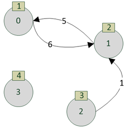
Fig. 591. Initial graph
If we get weakly connected add-ins for this graph, two add-ins will be identified:
-
Component 1: {0, 1, 2}.
-
Component 2: {3}.
Or in a graphical form:
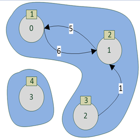
Fig. 592. Low cohesion components
If we get strongly connected add-ins for this graph, three add-ins will be identified:
-
Component 1: {0,1}.
-
Component 2: {3}.
-
Component 3: {2}.
Or in a graphical form:
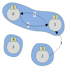
Fig. 593. High cohesion components
The selection of the high and low cohesion components does not depend on the order in which the equations and coefficients of the variables are specified. The distinguishing of high cohesion components without any requirement of a connection within the components depends on the order in which the equation and variable definitions are input to the mechanism for solving systems of linear equations. Thus, if the equations and coefficients are set in the natural order (top to bottom, left to right), then three components will be distinguished (similar to the distinguishing of high cohesion components):
-
Component 1: {0, 1}.
-
Component 2: {2}.
-
Component 3: {3}.
This is shown graphically in fig. 593.
But if you bring the equation (2) parameters formation to the beginning, the distinguishing of high cohesion components that do not require cohesions within components will result in two components similar to the distinguishing of low cohesion components:
-
Component 1: {0, 1, 2}.
-
Component 2: {3}.
This is shown graphically in fig. 592.
In 1C:Enterprise language, the above will look as follows:
Solver = New SystemOfLinearEquationsCalculation;
NodeData = New ValueTable;
NodeData.Columns.Add("EquationNumber");
NodeData.Columns.Add("FreeCoefficient");
String = NodeData.Add();
String.EquationNumber = 0;
String.FreeCoefficient = 1;
String = NodeData.Add();
String.EquationNumber = 1;
String.FreeCoefficient = 1;
String = NodeData.Add();
String.EquationNumber = 2;
String.FreeCoefficient = 1;
String = NodeData.Add();
String.EquationNumber = 3;
String.FreeCoefficient = 1;
RelationData = New ValueTable;
RelationData.Columns.Add("EquationNumber");
RelationData.Columns.Add("VariableNumber");
RelationData.Columns.Add("Coefficient");
String = RelationData.Add();
String.EquationNumber = 0;
String.VariableNumber = 0;
String.Coefficient = 1;
String = RelationData.Add();
String.EquationNumber = 0;
String.VariableNumber = 1;
String.CoefficientNumber = 5;
String = RelationData.Add();
String.EquationNumber = 1;
String.VariableNumber = 0;
String.Coefficient = 6;
String = RelationData.Add();
String.EquationNumber = 1;
String.VariableNumber = 1;
String.Coefficient = 2;
String = RelationData.Add();
String.EquationNumber = 1;
String.VariableNumber = 2;
String.Coefficient = 1;
String = RelationData.Add();
String.EquationNumber = 2;
String.VariableNumber = 2;
String.Coefficient = 3;
String = RelationData.Add();
String.EquationNumber = 3;
String.VariableNumber = 3;
String.Coefficient = 4;
Solver.RelationDataSource = RelationData;
Solver.EquationsInRelationsColumn = "EquationNumber";
Solver.VariablesInRelationsColumn = "VariableNumber";
SystemOfLinearEquationsDescription = Solver.SystemsDescription.Add();
SystemOfLinearEquationsDescription.FactorsInRelationsColumn = "Coefficient";
LowCohesion = Solver.GetConnectedComponents(ConnectedComponentsOfSystemOfLinearEquationsCalculationGettingMethod.WeaklyConnectedComponents);
HighCohesion = Solver.GetConnectedComponents(ConnectedComponentsOfSystemOfLinearEquationsCalculationGettingMethod.StronglyConnectedComponents);
HighCohesionWithoutRequirement
= Solver.GetConnectedComponents(ConnectedComponentsOfSystemOfLinearEquationsCalculationGettingMethod.StronglyConnectedComponentsWithNoInnerConnectionRequired);As a result of running this example, the variables will have the following values:
-
LowCohesion. Value table that contains low cohesion components.
-
HighCohesion. Value table that contains high cohesion components.
-
HighCohesionWithoutRequirement. Value table that contains high cohesion components without any requirement of a connection within the components. This variant will identify components similarly to high cohesion components.
If the example is modified, namely:
- strings:
String = NodeData.Add();
String.EquationNumber = 2;
String.FreeCoefficient
= 1;shift right after the string:
NodeData.Columns.Add("FreeCoefficient");- strings:
String = RelationData.Add();
String.EquationNumber = 2;
String.VariableNumber = 2;
String.Coefficient
= 3;shift right after the string:
RelationData.Columns.Add("Coefficient");then, after the example execution, the HighCohesionWithoutRequirement table will contain the components similar to the low cohesion components.
34.1.3. Recommendations for using the cohesion component search feature
The following scenarios for using the cohesion component search mechanism are recommended.
Using search for low cohesion components
The simplest algorithm that divides a system of linear equations into completely unconnected parts. Each of these parts can be:
-
Changed without affecting the solution of other parts of the system of linear equations.
-
Solved independently from other parts of the system of linear equations.
-
Subjected to any additional processing without affecting the solution of other parts of the system of linear equations.
It is not recommended that you separately and independently solve any parts of the system of linear equations if they are small (for example, it is more efficient to solve 100 parts of the system with 10 equations together than separately).
We recommend that you search for low cohesion components when an iterative solution of the system of linear equations is necessary. Solve some part of the system of linear equations, subject the source system to additional processing, and solve the changed system. In this case, the following method is recommended:
-
Separate low cohesion components.
-
Find the components containing the changed part of the system of linear equations (these components will be called "changed"). The remaining components will be called "unchanged". Then follow these steps:
-
Solve the changed and unchanged parts independently.
-
Change the components as required.
-
Solve the changed components again.
-
Unite the solutions of the unchanged components and the resulting solution of the changed components to obtain the general solution of the source system of linear equations.
-
Using search for high cohesion components
It is recommended that use the mechanism when the use of the mechanism for finding low cohesion components did not bring the expected result: too few low cohesion components were selected (or only one component was selected).
High cohesion components are more "dense" subgraphs of the source graph.
It is recommended that you try to build high cohesion components, manually or automatically analyze what connections exist in the source graph between the selected high cohesion components, and attempt to remove them by one of the following ways:
-
Edit source data.
-
Change the model according to which the system of linear equations was formed.
-
Temporarily delete these edges according to the following scenario:
-
Temporarily delete the edges connecting the high cohesion components.
-
Calculate low cohesion components. If all edges connecting two high cohesion components are removed, during further building of low cohesion components, these components will form low ones. It means if you remove all paths between the high cohesion components, the high and low cohesion components will look the same later on.
-
The required calculation is performed according to one of the scenarios specified in the "Using search for low cohesion components".
-
Return the temporarily deleted edges to the source graph.
-
Additionally process relaxation for the system of linear equations solution. The relaxation is necessary because the temporarily deleted edges may (and most probably will) change the system of linear equations final solution. For more efficient and simple relaxation, it is also recommended that you test the stability of the solutions of the system of linear equations parts separated using search for low cohesion components.
-
Using the search for components from the system of linear equations calculation
This mechanism, first of all, is intended for effective debugging and deeper understanding of the operation of the mechanism for calculating systems of linear equations. Use it in cases of manual analysis of systems of linear equations. The components that this mechanism builds (for any vertex of a component, there is no path to any vertex of any other component) depend on the numbering order of the vertices, but allow you to iteratively analyze the system of equations, starting from the components numbered 0 and moving farther along the components because the component numbered 0 is guaranteed not to be connected to subsequent components oriented by edge.
This method is recommended for use in the following situations:
-
The system of linear equations is very large, but the user wants to understand the main connections: which vertices have the greatest impact on other vertices. To do this, it is necessary to iterate through the cohesion components, analyzing which vertices are included in the equations with the largest coefficients. Based on the results of this analysis, you can analyze the solution stability. Slightly change the coefficients at the key vertices and see how much the final solution of the system of linear equations changes.
-
Manual calculation result check. Analysis of situations when there is an overflow of values in the solution of the system of linear equation, or when there is no vertex in the solution. This might happen when some coefficients of the system of linear equations are not specified or specified incorrectly.
34.2. Integration with 1C:Analytics
34.2.1. General information
The analytics system is a separate 1C:Enterprise add-in you can use to visualize and interactively analyze 1C:Enterprise infobase data. The 1C:Enterprise implements "visible" and "invisible" (for the user) parts that are necessary for users to be able to use the analytics system. The "visible" parts include a standard function that allows you to integrate the analytics system and 1C:Enterprise platform, and a client application menu item you can use to open the 1C:Analytics interface. Another "visible" part is a checkbox for setting up infobase publishing on the web server. The "invisible" part includes an API that allows 1C:Enterprise to interact with the analytics system. All data exchange is performed via this API.
In order for the user to be able to use the analytics system, the following steps must be completed:
-
Publish the 1C:Enterprise infobase on the web server. When you publish it, select the Publish the Analytics checkbox.
-
Using the standard function of the 1C:Enterprise, the address of the 1C:Analytics server is specified in the required infobase.
-
The required users will get the AnalyticsSystemClient access right (see Access rights description).
-
For users who have been granted this right, a command to run the client part of the analytics system becomes available in the client application interface.
1C:Analytics installation and setup are not covered in this documentation. In addition to the client application menu command, you can access the analytics system using the address generated as follows: http://host/base/ans. Let's consider the address components in more detail:
-
http://host/base. Standard URL used to access the infobase using the web client. If separators are present, specifying separator values using the Z parameter of the command-line for the client application startup is not supported.
-
ans. Indicates that the analytics system client is being called.
http://host/base/ans/data will be used to allow the analytics system to access the infobase data. To get both URLs, publish the infobase with the Publish the Analytics checkbox selected.
Users are authenticated by 1C:Enterprise. If the user uses the analytics system URL of the http://host/base/ans type, the web client authentication dialog box is used. If you start the analytics system from a client application, authentication data is transferred from the 1C:Enterprise client application.
34.2.2. Application programming interface
To interact with the analytics system from 1C:Enterprise language, use the AnalyticsSystem global context property. For simplicity, the AnalyticsSystem method prefix will be omitted in the documentation. It is evident that such omissions are unacceptable in examples and real applications.
From 1C:Enterprise language, you can:
-
Set and get the 1C:Analytics server address. To do this, use the SetAnalyticsSystemServerAddress() and GetAnalyticsSystemServerAddress() methods.
-
Navigate to the analytics system object. To do this, use the Open()method.
34.3. Regional settings
Regional settings are a set of parameters that defines some user interface settings such as language, country, time zone, date and time format, presentation of Boolean values, and so on. In the 1C:Enterprise, regional settings can be defined either for the entire infobase or for a specific user session.
Regional settings of the infobase can be performed interactively (using the dialog box in the Designer) and using the 1C:Enterprise language. To change regional session settings, use 1C:Enterprise language. In this section, you can read about operations with regional settings using 1C:Enterprise language.
In 1C:Enterprise, regional settings are described by the InfoBaseRegionalSettings object. To get the regional infobase settings, use the GetInfoBaseRegionalSettings() global context method. To change the current infobase settings, use the SetInfoBaseRegionalSettings() global context method. To change regional infobase settings, the user executing the method must have the Administration access right.
In general, the InfoBaseRegionalSettings object properties correspond to the Regional infobase settings dialog box fields. Let's take a look at these properties:
-
LocaleCode. One of the available locale codes. To get available locale codes, use the GetAvailableLocaleCodes() global context method. Setting the localization code determines the default values for the settings of generating the presentation of values of the Number, Date, Boolean types, if the settings are not specified explicitly.
-
UseCurrentSessionSettings. If the property is set to True, the regional settings of the session in which the presentation is generated are used to generate the presentation of values of the Number, Date, and Boolean type. If the property is set to False, the values set as infobase settings will be used to generate the presentation. The GetInfoBaseRegionalSettings() method is used to get such values.
-
NumbersDecimalSeparator. One-character string to be used to separate the integer and decimal parts when getting a presentation of the Number type data. If the string is empty, the current session setting will be used.
-
NumbersDigitGroupSeparator. One-character string to be used to separate the digit groups when getting a presentation of the Number type data. If the string is empty, the current session setting will be used.
-
NumbersDigitGroupFormat. Sequence of characters that defines the rules for grouping digits in number presentation. The description of the format string is given in the description of the Regional infobase settings dialog box. If the string is empty, the current session setting will be used.
-
NegativeNumberPresentationSets. Presentation of negative numbers. Value presentations are enclosed in parentheses in the Regional infobase settings dialog box:
| A property value | Presentation and example | Description of behavior |
|---|---|---|
| -1 | Auto | Use the current session setting. |
| 0 | (1.1) | Number in parentheses. |
| 1 | -1.1 | Minus sign before the number (no space). |
| 2 | - 1.1 | Minus sign before the number. Minus is separated from the number by a space. |
| 3 | 1.1- | Minus sign after the number (no space). |
| 4 | 1,1 – | Minus sign after the number. Minus is separated from the number by a space. |
-
BooleanFalsePresentation. Sets the False value presentation. If the string is empty, the current session setting will be used.
-
BooleanTruePresentation. Sets the True value presentation. If the string is empty, the current session setting will be used.
-
DatePresentationFormat. Specifies the date format. The description of the format string is given in the description of the Regional infobase settings dialog box. If the string is empty, the current session setting will be used.
-
TimePresentationFormat. Sets the time presentation format. The description of the format string is given in the description of the Regional infobase settings dialog box. If the string is empty, the current session setting will be used.
-
FirstDayOfWeek. Defines the day of the week that is considered the beginning of the week. The description of the features of determining the first day of the week is given in the description of the Regional infobase settings dialog box. If the value of this property is 0, the day of the week's start is determined in accordance with the localization code of the infobase.
In addition to the properties that describe the generation method of values presentation, the InfoBaseRegionalSettings object allows you to obtain a presentation of a value of a particular type, formatted in accordance with the settings specified in this object:
-
Presentation(). Generates an arbitrary value presentation.
-
TimePresentation(). Generates time presentation string with no date specified.
-
DatePresentation(). Generates a date presentation string with no time specified.
-
GetFirstDayOfWeek(). Returns the number of the first day of the week.
To get the regional settings of the current session, use the GetSessionRegionalSettings() global context method. The method returns the regional settings as the SessionRegionalSettings object. The properties of this object are similar to the properties of the InfoBaseRegionalSettings object, but consider the language features of the current session. In particular, the SessionRegionalSettings object considers the following changes:
-
The interface language, which can be changed using the /L command of the startup command line of the client application. The system interface language can only include a value from the list of 1C:Enterprise interface languages. To access the interface language code, use the SessionRegionalSettings.InterfaceLanguageCode property.
-
The locale language, which can be changed using the /VL command of the startup command line of the client application. To access the locale language code, use the SessionRegionalSettings.LocaleCode property.
Regional session settings are generated before you start the session. You cannot change them while the session is running. So, the SessionRegionalSettings object is read-only.
See also:
-
Access rights (see Access rights description).
-
Regional infobase settings dialog box.
34.4. Activating software licenses
1C:Enterprise platform provides an API you can use to implement a dialog box for obtaining software licenses. To access this dialog box, open Designer and click Main menu – Tools – License acquisition. To access this API, use the LicenseAcquisition global context property. The license acquisition manager is available through this property. Therefore, calling the API methods will look as follows: LicenseAcquisition.CalledMethodName(). For simplicity, the name of the global context property will be omitted in the following text. Obviously, this simplification is not applicable in 1C:Enterprise language code.
This section assumes that the reader understands what the licensing system of "1C:Enterprise" is, knows about different license types, and comprehends their differences.
To activate a software license, follow these steps:
-
Get software license parameters.
-
Get license owner data.
-
Determine the physical object to which the activated license will be bound.
-
Generate a request for a license.
-
Get (activate) a license.
Let us consider the above in detail.
There are two forms of software licenses: regular and developer license. By regular licenses, we mean all software licenses described in the corresponding section (client, server, PROF, CORP, and so on). Since the regular license and the developer license have a number of differences in installation data, the following table will list these differences:
| Regular | For developers | |
|---|---|---|
| License parameters | License parameters are listed in a special form included with the software license distribution package. This form requires the distribution package number and the PIN that will be used for activation. | License parameters include username and password to a confirmed account on the [developer](https://developer.1c.ru) portal. |
| License owner data | Entered when activating the license and can be either company data or individual data. | License owner can be only an individual whose data is automatically obtained from the [developer](https://developer.1c.ru) portal in the amount provided by the portal. |
| Option of blinding a license upon activation | Computer or dongle. | Computer only. |
The developer portal in the table implies one of the websites: https://developer.1c.ru or https://1c-dn.com.
It should also be noted that license activation for developers is not supported everywhere. To make sure the developer license can be activated at a given location and point in time, use the GetDeveloperLicenseUsageAvailability() method. The developer license can only be activated if this method returns True. Note that when implementing a developer license activation from 1C:Enterprise language, the user must agree to the 1C license agreement before activation. To get this agreement, call the GetDeveloperLicenseAgreement() method. Actual activation of a developer license implies that the user has read and agreed to the license text. The DeveloperPortal method parameter indirectly influences the returned License Agreement language:
-
developer.1c.ru. Text in Russian.
-
1c-dn.com. Text in English.
-
Empty string.
Let's look at the actual process of activating a license from the 1C:Enterprise language. The first step is to use the license owner parameters to complete the request for a license. The request for a license uses the LicenseAcquisitionRequest object. Let's briefly review its properties:
-
Filling in the object properties depends on which license is planned to be activated:
-
Developer license: only the AccountName and AccountPassword properties must be filled in. The other properties must not be filled in. The developer gets their AccountName and AccountPassword properties after the registration at the developer portal. It is recommended that you specify the following properties for developers when activating the license:
- DeveloperPortal. Portal where you need to get a license. Possible values: an empty line (default value), developer.1c.ru, or 1c-dn.com. The value is not used when you activate the license. It is used in a license acquisition dialog box (in Designer or standard client application function) to display the developer portal URL.
-
When activating "regular" licenses, all other properties must be filled in, except for the AccountName and AccountPassword properties. These properties include:
-
RegistrationNumber. Registration number of the software license to be activated.
-
PIN. PIN to activate the software license. No software license was activated using this PIN. The PIN is specified without separators.
-
OldPin. When you re-obtain a software license using a backup PIN (for example, when key binding parameters are changed), enter the PIN used to activate the software license you want to update. The PIN is specified without separators.
-
Parameters describing the individual or legal entity that is the owner of the software license being activated.
-
-
-
ForAllUsers. Specifies whether the file with an activated license will be placed in the current user directory or in the directory for all users.
-
LicenseFileName. Name of the file where the information of the activated software license and human-readable information will be placed after the activation process is successfully completed.
-
FingerprintParameters. Specifies which hardware the software license will be bound to upon activation. You can bind it to computer parameters (the LicenseAcquisitionComputerFingerprintParameters object) or HASP dongle (the LicenseAcquisitionKeyFingerprintParameters object).
As mentioned earlier, the developer license can only be bound to the computer parameters.
-
AgentAddress. Address of the 1C:Enterprise server agent. Specified when the software license is activated not for the current computer, but for the computer on which the 1C:Enterprise server cluster is deployed.
-
Port. Number of the IP port served by the 1C:Enterprise server agent. The server agent address is specified in the AgentAddress field.
-
RequestTime. Date and time when the license request was created. If the LicenseFileName property is not specified, the date and time of receiving the license are used to form the name of the file with the activated software license.
The created license request will be used in the following steps. If you do not want to enter the entire array of necessary information in the future again, save the request using the SaveLicenseAcquisitionRequest() method. You can reuse the saved data both using the LoadLicenseAcquisitionRequest() method and in the dialog box for Designer license acquisition (the data will be loaded automatically).
There are two methods available to get the equipment parameters to which a software license may be bound:
- GetComputerFingerprintParameters(). This method allows you to get the current computer parameters or the parameters of the computer where the server cluster is deployed. In this case, the cluster parameters are passed as method parameters. The method returns the LicenseAcquisitionComputerFingerprintParameters object, which contains the key hardware parameters. The hardware parameter list depends on the operating system of the computer for which the binding parameters are obtained.
If you obtain the binding parameters for the computer where the server cluster is deployed, the versions of the client application and the cluster must be equal.
- GetAvailableKeys(). This method returns an array of LicenseAcquisitionKeyFingerprintParameters objects that contains a list of HASP dongles. They are available when you call the method on the current computer. Note that the availability of a particular dongle may change over time. Therefore, we recommend that you use either the local dongles of the computer on which the license is being installed or the dongles available in the current local network with at least one license available to verify the binding.
Once all the necessary data is collected, make sure the license can be activated and save the file with the activated license to the required place in the file system. To do this, use the GetLicenseAcquisitionAvailability()method. This method will use the AgentAddress, Port, and ForAllUsers properties of the LicenseAcquisitionRequest object. The method checks that the computer with the server agent or the current computer has the ability to save the license file to the local user directory or to the all users directory. If it is impossible to acquire the license, the object describing the verification result passes ErrorDescription, which can be displayed to the user. It is also possible that as a result of executing the GetLicenseAcquisitionAvailability() method, the value of the GetLicenseAcquisitionAvailability.Available property will be set to True, but the GetLicenseAcquisitionAvailability.ErrorDescription property will also be filled in. For example, when an incorrect file name is specified in the LicenseAcquisitionRequest.LicenseFileName property.
After you completed all the preparations, you can activate the license. To do it, you can:
-
The easiest way is to obtain the license automatically. Use the AcquireLicenseAutomatically() method. If successful, the activated license will be saved with the name specified in the LicenseAcquisitionRequest.LicenseFileName property.
-
The next way is to acquire the license over the phone. Several methods are used for this:
-
CreateLicenseAcquisitionRequestByPhone(). The method generates a sequence of numbers that you need to report to the Licensing Center over the phone. Then it will be necessary to provide the checksum of the generated sequence to verify that the data was transferred to the Licensing Center without loss or distortion. To generate a checksum of the generated sequence, use the GenerateLicenseAcquisitionCodeStringChecksum() method. In response to the transferred information, the Licensing Center will provide its own sequence of digits.
-
AcquireLicenseByPhone(). Pass the license request and the Licensing Center response received in the previous step to this method.
-
The last way to activate a license is to use media. Activating a license this way is similar to activating a license by phone. Two methods are also used:
-
CreateLicenseAcquisitionRequestOnStorageDevice(). The method generates a sequence of characters that you need to send to the Licensing Center by email or on any other storage medium. In response to this, the Licensing Center will provide its own sequence of digits.
-
AcquireLicenseFromStorageDevice(). Pass the license request and the Licensing Center response received in the previous step to this method. The Licensing Center response must be read from the file as one string. For example, you can use the TextDocument object for that.
Finally, let's take a look at auxiliary functions you can use to implement various service operations. To get various Licensing Center parameters, use the following methods:
-
LicensingCenterAddress(). The method returns the URL of the Licensing Center website. By navigating the received URL, you can get a license on electronic media.
-
LicensingCenterEmail(). Returns the Licensing Center email address. Using the received address, you can get a license on electronic media.
-
LicensingCenterPresentation(). The method generates a text presentation of the used Licensing Center. It can be used to generate the header of the dialog box for receiving licenses.
-
LicensingCenterPhoneNumber(). The method returns a phone number that can be used to receive a license by phone.
-
GetLicensingCenterAvailability(). Shows whether the Licensing Center is available from the current computer.
When receiving characteristics of the Licensing Center, it's necessary to specify the country code for which the characteristic is required. For these methods, the following rule applies for specifying the parameter describing the country:
-
Empty string. The Licensing Center is determined in accordance with the infobase locale code.
-
kk, kk_KZ. The Kazakh Licensing Center is used.
-
ru, ru_RU. The Russian Licensing Center is used.
-
uk, uk_UA. The Ukrainian Licensing Center is used.
If a developer wants to implement their own license activation dialog box, they might need to specify the country where the license owner is located. A two-letter code of this country will then be specified in the LicenseAcquisitionRequest.Country property. To match country codes in the license request with country codes of the Licensing Center, use the GetAvailableCountries() method.
Thus, you can write code in 1C:Enterprise language that describes the automatic acquisition of the 1C:Enterprise software license. Note that this is a demo code, not a complete tool.
Procedure ActivateLicenseAtServer()
FingerprintParameters = LicenseAcquisition.GetComputerFingerprintParameters();
ActivationRequest = New LicenseAcquisitionRequest;
ActivationRequest.ForAllUsers
= True;
ActivationRequest.RequestTime
= CurrentSessionDate();
ActivationRequest.RegistrationNumber
= "8123456789";
ActivationRequest.PIN = "123456789098765";
ActivationRequest.FingerprintParameters
= FingerprintParameters;
ActivationRequest.Company = "License owner";
ActivationRequest.LastName = "LastName";
ActivationRequest.Name = "Name";
ActivationRequest.MiddleName
= "MiddleName";
ActivationRequest.Email = "email@email@example.com";
ActivationRequest.Country = "RU";
ActivationRequest.City = "Moscow";
ActivationRequest.Street = "Red Square";
ActivationRequest.House = "1";
ActivationRequest.LicenseFileName
= "License file-" + Format(ActivationRequest.RequestTime, "DF=yyyyMMddHHmmss");
LicensingCenterAvailability
= LicenseAcquisition.GetLicensingCenterAvailability();
If LicensingCenterAvailability.Available Then
AcquisitionAvailability = LicenseAcquisition.GetLicenseAcquisitionAvailability(ActivationRequest);
If AcquisitionAvailability.Available Then
LicenseAcquisition.AcquireLicenseAutomatically(ActivationRequest);
Else
Raise
AcquisitionAvailability.ErrorDescription;
EndIf;
Else
Raise
LicensingCenterAvailability.ErrorDescription;
EndIf;
EndProcedureSee also:
-
License types.
-
"1C:Enterprise" licensing system
-
Software licenses.
-
Key parameters.
34.5. Notification of the client application from the server side
When developing information systems, there may be a need to notify the client application that some action has been completed on the server side. If the action is not an explicit call to server code from the client application code, then the interaction system can be used for such notification. This method requires the connection of the infobase to the collaboration system. If the only feature of the collaboration system being used is the notification of the client application from the server, this may be inconvenient for the developer.
1C:Enterprise provides the ability to notify the client application from server-side code without requiring the use of the collaboration system. For this purpose, the system has implemented a client notification manager, which is accessible using the ClientNotifications global-level context property. Calling API methods will look as follows: ClientNotifications.CalledMethodName(). For simplicity, the name of the global context property will be omitted in the following text. Obviously, this simplification is not applicable in 1C:Enterprise language code.
The general logic of using notifications is very simple:
-
The server application performs some background jobs that must notify the client part of the application about the results of its work.
-
To do this, the background job must use the SendNotification() method.
-
The client part must subscribe to receive notifications using the AttachHandler() method. If the handler is not connected, notifications cannot be processed.
-
After you no longer need to process notifications, you must disable the notification handler (one or all) using the DetachHandler() method.
To send a notification to the client application, you should use the SendNotification() method, which is available on the server side or the thick client. The method has the following parameters:
-
Key is a String type value that will allow to uniquely determine which notification handler will be called. If the Undefined value is passed as a parameter when calling the method, then such a notification will be processed only by those handlers that were registered for the key with the Undefined value.
-
Data is a value of an arbitrary type, which allows transferring any data to the client application. Any value that can be passed to the client side upon completion of a client/server call can be transferred.
-
Recipients is an array of numeric values. Using this parameter, you can send a notification to specific sessions, the numbers of which are listed in the array. For example, you can send a notification only to sessions of a specific user. The numbers of the recipient sessions can be retrieved from the InfoBaseSession.SessionNumber property, and you can find out that this is the session of the required user using the InfoBaseSession.User property. If you need to get the number of the session that started the background job, use the BackgroundJob.ParentSessionNumber property. If the client application did not start the background job (for example, the background job was generated by a scheduled job), this property will be set to 0.
In terms of notification delivery, it is necessary to distinguish between the described service and the mechanisms of the collaboration system. The collaboration system allows sending a message to the user(s) of the infobase regardless of whether the user is currently working with the infobase or not. Client application notifications are sent to an infobase session(s), which must expect incoming notifications (subscribe to notification processing). The system will attempt to deliver notifications to all sessions for which information is available at the time the notification is sent. When sent, the notification is written to a special storage, where it will remain until it is received by the recipient or until it is deleted. Successful execution of the SendNotification() method means that the notification was saved to the storage. The notification is deleted from the storage after the 1C:Enterprise system loses information about the session for which the notification was intended. Maintenance of the notification storage (delivery of notifications and storage cleanup) is performed by:
-
In the client/server mode of the infobase, a special cluster service.
-
In a file infobase with direct access: any client application connected to this infobase.
-
In the file mode of the infobase with access via a web server, a web server extension that services the publication.
After sending a message, it is necessary to receive this message on the client side and process it. To do this, a notification handler must be connected on the client side. For this, the AttachHandler() method is used, which has the following parameters:
-
Key is a String type value. Allows to "subscribe" to a specific category of notifications only. Unique parameter value is understood under "category" term, for example, the CurrencyRates value will mean all notifications related to exchange rates. If the value of this parameter is Undefined, then this handler will be called for any notifications.
-
Handler. It contains a value of the NotificationDetails type. The method, whose name is used when creating the object, will be called when a notification is received.
Use the DetachHandler() method, if the client application no longer needs to process a particular category of notifications. The key value that was used when connecting the handler is passed as a parameter. In this case, the handler "subscribed" to this key value will be disabled. If the Undefined value is passed as a parameter, all handlers in this client application will be disabled. The handler will also be disabled if the form in whose module the notification handler was connected is closed.
Using notifications looks like the following code:
// handler connection (client application module)
Procedure OnStart()
Handler = New NotifyDescription("NotificationHandler", HandlersMethods);
ClientNotifications.AttachHandler(Undefined, Handler);
EndProcedure
// disabling all handlers (client application module)
Procedure OnExit()
ClientNotifications.DetachHandler();
EndProcedure
// handler method (HandlersMethods common module)
Procedure NotificationHandler(Data, AdditionalParameters) Export
Message("Data = "
+ Data);
EndProcedure
// send notification (background job)
Data = New Map;
Data.Insert(WorkWithCurrencies.GetCurrencyByCode(CurrencyCode), ExchRateValue);
ClientNotifications.SendNotification("CurrencyRates", Data);34.6. Users, authentication and 1C:Enterprise language
34.6.1. General information
1C:Enterprise can provide simultaneous work with application data for any number of users. Each application user is described by some characteristics (name, password, available types of authentication, and so on) and access rights that are inherent to this user. User management can be performed both interactively, using the Designer tools, and using the 1C:Enterprise language (will be discussed in this section).
The InfoBaseUser object is intended for working directly with the infobase users, and the infobase user manager is intended for working with all users (creation, obtaining the current user, selecting users by certain criteria). To access manager, use the InfobaseUsers global context property. A call to any manager method looks like InfobaseUsers.Method().
The infobase contains a certain set of parameters that determine what the user passwords will be and what will happen with these passwords in various situations. For this purpose, 1C:Enterprise provides a manager of additional authentication settings. A manager has a certain set of properties and methods, as well as a set of objects that are used by the manager. To access the properties and methods of the additional authentication settings manager, use the AdditionalAuthenticationSettings global context property. The call looks like AdditionalAuthenticationSettings.Property or AdditionalAuthenticationSettings.Method.
For simplicity, the prefixes of a particular manager (InfobaseUsers or AdditionalAuthenticationSettings) will be omitted in the documentation. It is evident that such omissions are unacceptable in examples and real applications.
34.6.2. Managing users
1C:Enterprise platform provides the ability to manage users from the 1C:Enterprise language:
-
Create a new user.
-
Get a user specified by name or UUID.
-
Get a list of infobase users.
Let's have a closer look at these operations. It should be understood that different operations require different access rights. The documentation will not explicitly specify the required rights for each operation. Syntax Assistant contains the necessary information.
To create a user, use the CreateUser() method of the infobase user manager. The method will return an object of the InfoBaseUser type, which does not contain any data. Next, the user parameters need to be filled in, and the object saved to the infobase.
IBUser = InfobaseUsers.CreateUser();
IBUser.Name = "User";
IBUser.FullName = "User created from the 1C:Enterprise language";
IBUser.StandardAuthentication
= True;
IBUser.CannotChangePassword
= False;
IBUser.ShowInList = False;
IBUser.Write();As a result, a user with the User name will be created in the infobase, with enabled 1C:Enterprise authentication and a missing set of roles. To specify the roles available to the user, use the Roles property of the InfoBaseUser object. The value of this property is the UserRoles collection, to which you can add the required roles and remove roles that the user no longer requires.
Note. Note. If the Write() method is executed during an active transaction, then after the transaction is completed, obtaining the user using the FindByName(), FindByUUID(), GetUsers() methods of the InfoBaseUsersManager object in all sessions of this infobase will return the recorded state of the user. But the result of executing the CurrentUser() method in all sessions, including the current one, will return the user state at the time the corresponding session started.
User ability to perform a particular authentication method is determined by the set of Authentication... properties of the user itself, and the availability of a particular client application is determined by the set of access rights of this user (and is determined by the user's access rights).
The UserMatchingKeys property is required to specify key values for different OpenID Connect authentication providers or access tokens, by which the user of the 1C:Enterprise infobase and the user of the provider (or access token) will be compared. The value from this property will be used if the matchingKey value is specified for the authenticationUserPropertyName provider parameter when configuring OpenID Connect authentication in the default.vrd file.
The AssignmentRuleKey property allows you to group users to assign user connections to specific production servers. In the server cluster, use the functionality assignment rules which will enable this assignment.
The PasswordDoesNotSatisfyRequirements property is set if, during authentication, it is determined that the user's password does not satisfy the password policy requirements of the user or the infobase. When a user password is changed, this property is set to False. The property is not writable because it is a derived value from the user password and password policy.
The DataSeparation property is intended for use if the infobase uses a data separation mechanism.
If you need to get details of a user, you can use the following methods:
-
CurrentUser(), returns the details of the user under whose identity the current session is running. This is "we ourselves".
-
FindByName(), returns the user whose name is specified by the method parameter. If the username is not specified, the "default user" is returned.
-
FindByUUID(), returns the user whose UUID is specified by the method parameter (InfoBaseUser.UUID).
To get details of all infobase users (or data area), use the GetUsers() method, which will return an array of objects of the InfoBaseUser type that are available to the current user with the current access rights. If you need to select only those users who match a certain criterion, you must do this yourself: first, retrieve the list of all users, and then use the 1C:Enterprise language to select the ones you need.
34.6.3. Saving authentication
To configure the authentication saving mechanism from the 1C:Enterprise language, use the additional authentication settings manager, which provides the GetAuthenticationAutoSaveSettings() and SetAuthenticationAutoSaveSettings() methods. These methods work with an object of the AuthenticationAutoSaveSettings type.
This object provides the following set of properties:
| Property | Description |
|---|---|
| SavedAuthenticationLifetime | This property describes how long the token that stores the authentication parameters will be valid. Number. |
| AllowSaving | Enables/disables saving successful authentication for the current infobase (the Remember checkbox in the authentication dialog box). Boolean. |
| SaveByDefault | Specifies the default value for the Remember checkbox if saving successful authentication is enabled for the infobase. Boolean. |
To enable the ability to save successful authentication for the infobase, use code of the following type:
AuthenticationAutoSaveSettings
= AdditionalAuthenticationSettings.GetAuthenticationAutoSaveSettings);
AuthenticationAutoSaveSettings.AllowSave
= True;
AuthenticationAutoSaveSettings.SaveByDefault
= True;
AuthenticationAutoSaveSettings
= 56000;
AdditionalAuthenticationSettings.SetAuthenticationAutoSaveSettings(AuthenticationAutoSaveSettings);See also:
- Infobase parameters.
34.6.4. Password policy
34.6.4.1. General information
To assign different policies (set of requirements) to different users, use software tools for policy operations. These operations are based on the UserPasswordPolicy object. It contains properties that are identical to properties of the dialog box to edit infobase parameters. Besides, the UserPasswordPolicy object has the Name property that allows you to specify a unique name for a policy. With this object, you can also use the Write() and Delete() methods to perform the same-name operations.
To access the policy operation tool, use the UserPasswordPolicies global context property. This property gives you access to the manager of the user password policy. With this manager, you can use password policies of the current infobase and check whether the password complies with a certain policy. To call a manager method, use a command of the UserPasswordPolicies.Method() type. Let us take a closer look at the manager capabilities:
-
GetPolicies(). Returns an array of objects of the UserPasswordPolicy type that contains a list of saved policies.
-
FindByName(). Finds a user password policy with a specified name. Each policy has a unique name.
-
CreatePolicy(). Creates a new object of the UserPasswordPolicy type.
-
CheckPasswordComplianceWithPolicy(). Checks whether the password specified as a method parameter complies with the password policy.
Let us take a look at what the CheckPasswordComplianceWithPolicy() method does. The method receives a password to check as a required parameter with the Password name. If other parameters are not specified, the password is checked for compliance with the password policy set for the entire infobase. If the Policy parameter is set along with the password, the password is checked for compliance with the password policy specified in the parameter. If the InfoBaseUser parameter is also specified, the method checks the password reuse restriction by the user password history if password reuse check is enabled in the password policy used for checking (the infobase or specified in the Policy parameter).
As a result, the method returns the PasswordPolicyComplianceCheckResult system enumeration array. If the array is empty, the password meets the existing requirements. In general, there can be several reasons why a password does not comply with the policy. That is why, the method result is an array with all the reasons for password non-compliance with the policy. A system enumeration includes the following values:
| Value | Description |
|---|---|
| DoesNotSatisfyMinLengthRequirements | The password length is shorter than the minimum user password length (the Minimum password length/PasswordMinLength parameter). |
| DoesNotSatisfyReuseLimitRequirements | The password matches one of the recent user passwords. You can specify the number of passwords to check in the policy settings (the Deny password reuse among recent ones/PasswordReuseLimit parameter). |
| DoesNotSatisfyCompromiseCheckRequirements | The password was found in the password blacklist or in the password check service (the Password compromise check/ PasswordCompromiseCheck parameter). |
| DoesNotSatisfyComplexityRequirements | The password does not pass the password complexity check (the Password complexity check/PasswordStrengthCheck parameter). |
To specify a password policy different from the infobase policy for a certain user:
-
Create a new password policy with required settings. Save the policy in the infobase.
-
Find a user by name or UUID.
-
Set the created policy name to the PasswordPolicyName property of the InfoBaseUser object.
-
Save the user in the infobase.
To set a password policy for multiple users, follow the above algorithm for each user.
34.6.4.2. Setting a password change date
An object that describes an infobase user has some properties related to user password policies. Such properties include:
-
PasswordSettingDate. If the user has the Administration right, this property allows them to find out password change date and time. Otherwise, this property contains an empty date.
-
WritablePasswordSettingDate. This property allows you to specify password change date and time.
Let us take a look at how you can set a value for the PasswordSettingDate property:
-
The WritablePasswordSettingDate property is changed:
-
Data is written on behalf of a user with the Administration right:
- The PasswordSettingDate property is set to the WritablePasswordSettingDate property value.
-
Data is written on behalf of a user without the Administration right. A new user is created or data is changed for a user who executes the code in 1C:Enterprise language:
- If the password is changed or a new user is written, the PasswordSettingDate property receives a date and time when the InfoBaseUser object was written as a value.
-
-
The WritablePasswordSettingDate property is not changed:
- If the password is changed, the PasswordSettingDate property receives a date and time when the InfoBaseUser object was written as a value.
Note that the PasswordSettingDate property will not change if one of the following properties is changed before the InfoBaseUser object is written: Password, StoredPasswordValue, or WritablePasswordSettingDate. To get an actual password change date after the object is written, receive the object from the user list again (reread the user information).
34.6.4.3. Setting user password
To set a user password, you can use the following properties of the InfoBaseUser object:
-
Password. Allows you to specify a new user password. The property is write-only.
-
StoredPasswordValue. Contains a user password hash. This property is available for writing and reading. Note that you cannot recover the password value by the hash. You can use the property when you need to copy the current user list and set passwords to another infobase.
If the Password and StoredPasswordValue properties are set when the InfoBaseUser object is written, the Password property value will be written to the infobase, and the StoredPasswordValue property value will be ignored and filled with a hash function value from the Password property. If only the StoredPasswordValue property is changed when the InfoBaseUser object is written, this value will be written to the infobase.
To automatically generate user passwords (for example, to create users in bulk before launching the system), you can use the RandomPasswordGenerator object. This object allows you to generate random passwords using 1C:Enterprise language.
User = InfoBaseUsers.FindByName(UserName);
Generator = New RandomPasswordGenerator();
NewPassword = Generator.RandomPassword();
User.Password = NewPassword;
User.Write();The option shown in the example uses the password requirements specified in the infobase settings. The default password length is 7 characters, but if a longer value is specified in the infobase settings, it is used. To specify the exact length of the generated password (without using the infobase settings), you can use the PasswordLength parameter of the RandomPassword() method. If the MemorablePassword parameter of the same method is set to True, the generated password will look more like an ordinary word and will be more convenient to remember. For exanple, Anefeg3. If the MemorablePassword parameter is set to False, the password will be just a random sequence of letters and numbers. For exanple, JCcQGW3.
There are two methods for operations with the stored password value: EvaluateStoredUserPasswordValue() and CheckUserPasswordComplianceWithStoredValue(). The first method allows you to get the value of the stored password value. This method might be useful when the user parameters are set outside the infobase where this user needs to be created. The parameters of the user to create will (or can) be transferred over open or weakly secure communication channels. To avoid transferring the password specified by the user as plain text, you can transfer the value obtained using the EvaluateStoredUserPasswordValue() method, and assign this value to the StoredPasswordValue property of the new user in the target infobase. Remember that sequential calls of the EvaluateStoredUserPasswordValue() method for the same password may lead to generating different hashes for some hashing algorithms. This behavior is normal.
The CheckUserPasswordComplianceWithStoredValue() method allows you to check that a password specified in the method parameter in plain text corresponds to the stored password value. The stored password value can be specified as a string with the stored password value or by the InfoBaseUser object. If the infobase user is specified, the system will check whether the password of the specified user is actually transferred. It will also be checked that the password matches the current password complexity settings.
Another property related to the user password is the PasswordHashAlgorithmType property. This property contains a value of the UserPasswordHashAlgorithmType type: The user password hashing algorithm is set in the infobase parameters. The property value is derived from the password and cannot be set forcibly.
The stored value of a specific user password changes during user authentication if the type of password hashing algorithm in the infobase differs from the current type of the user hashing algorithm, as well as when changing the password. Thus, if the password hashing algorithm changes for the infobase, and the hashing algorithm of a particular user differs from the current infobase algorithm, it means that since the hashing algorithm change, the user has not authenticated in the infobase.
34.6.4.4. Changing infobase password requirements
requirementsYou can apply a password policy both for the entire infobase and for specific users. If you need to change password policy parameters for the infobase, you can use the following 1C:Enterprise language methods:
-
Action if password doesn't meet requirements: GetActionOnUserPasswordRequirementsViolationOnAuthentication()/SetActionOnUserPasswordRequirementsViolationOnAuthentication().
-
Deny password reuse among recent ones. GetUserPasswordReuseLimit()/SetUserPasswordReuseLimit().
-
Maximum user password lifetime. GetUserPasswordMaxEffectivePeriod()/SetUserPasswordMaxEffectivePeriod().
-
Minimum password length. GetUserPasswordMinLength()/SetUserPasswordMinLength().
-
Minimum user password lifetime. GetUserPasswordMinEffectivePeriod()/SetUserPasswordMinEffectivePeriod().
-
Password compromise check. GetUserPasswordCompromiseCheck()/SetUserPasswordCompromiseCheck().
-
Password complexity check. GetUserPasswordStrengthCheck()/SetUserPasswordStrengthCheck().
-
Password expiration notification period. GetUserPasswordExpirationNotificationPeriod()/SetUserPasswordExpirationNotificationPeriod().
34.6.5. Password recovery
To ensure the user password recovery work, set up this feature first, then enable it, and finally, ensure that each infobase user has the correct email address. You can perform all the above actions both manually (using the appropriate administration tools) and using 1C:Enterprise language.
You can recover password one of the following ways:
-
Use a website that the user will go to and perform a certain set of actions there. The entire password recovery logic must be implemented using the website the user will go to. The parameters of the data area for which the authentication dialog box is opened will be added to this hyperlink before navigation. Data area parameters are set in the same way as the Z command-line option of the client application startup. The resulting URL will be as follows: URL?Z= "separator values".
-
Use an email address and a new password confirmation code.
For OpenID authentication, the password is changed on the side of the authentication provider because it performs authentication. Once the password is changed, the user navigates to the provider authentication form. In this case, the password recovery method depends on capabilities provided by the OpenID provider used.
To configure the user password recovery feature, use the UserPasswordRecoverySettings object. This object is used by the GetPasswordRecoverySettings() and SetPasswordRecoverySettings() methods of the additional authentication settings manager.
The UserPasswordRecoverySettings object has the following properties:
| Property | Description |
|---|---|
| SMTPServerAddress | Sets the address of the SMTP server which will be used for sending emails. |
| VerificationCodeLength | Sets the length of the confirmation code for setting a new password. |
| VerificationCodeRefreshRequestLockDuration | Interval between two consecutive requests to change a password verification code. |
| Title | Text to be specified in the message header (the Subject field). |
| SenderName | Sender name. Text to be displayed in the email message as the email author (the From field). |
| UseSSL | Specifies whether it is necessary to use SSL connection to connect to the SMTP server. |
| MaxUnsuccessfulVerificationCodeValidationAttemptsCount | Specifies how many times the user can make mistakes when entering the confirmation code. Once the maximum number of attempts is exceeded, the received code becomes invalid. The user will need to request a new password recovery code. |
| PasswordRecoveryURL | Specifies the URL to navigate to if password recovery by URL is selected. |
| HelpURL | Specifies the URL to navigate to if the ShowHelpHyperlink property is set to True. |
| ShowHelpHyperlink | Specifies whether to display the URL in the authentication dialog box. |
| SMTPPassword | Sets the password of the user who connects to the SMTP server. |
| SMTPUser | Sets the name of the user who connects to the SMTP server. |
| SMTPPort | Sets the number of the network port that the SMTP server uses. |
| PasswordRecoveryMethod | Allows you to specify how the user password will be recovered. This property can take values with the InfoBaseUserPasswordRecoveryMethod system enumeration type: · No. The infobase does not use user password recovery. · GotoURL. The URL is used for password recovery. · SendVerificationCodeByStandardService. To recover the password, the 1C email service is used. In this case, you cannot change the email sender, subject, format, and content. Emails will always be sent from <recoverypassword@1c.com > <recoverypassword@1c.com> · SendVerificationCodeBySetParameters. The email service whose parameters are specified in the properties of the UserPasswordRecoverySettings object is used for password recovery. |
| VerificationCodeEffectivePeriod | Specifies the lifetime of the password change verification code. After expiration, the received code becomes invalid. The user will need to request a new password recovery code. |
| HTMLMessageText | HTML text, which is a template for an email with a password recovery code. The default text is <html><head></head> <body>Hello &UserPresentation, <div><br></div> <div>We've received the password reset request from &ApplicationPresentation.</div> <div><br></div> <div>Please, enter the <b>&VerificationCode</b> to reset your password.</div> <div><br></div> <div>If you didn't request password reset, contact your administrator.</div></body></html> The following variables can be used in an email: § ApplicationPeresentation. Presentation of the configuration used in the current infobase. § UserName. Username. § UserPresentation. Full user name. § VerificationCode. Confirmation code to change the password. The names of variables in the email must start with &. |
The simplest example of setting up password recovery is given below:
PasswordRecoverySettings = New PasswordsRecoverySettings();
PasswordRecoverySettings.PasswordRecoveryMethod = InfoBaseUserPasswordRecoveryMethod.SendVerificationCodeByStandardService;
AdditionalAuthenticationSettings.SetPasswordRecoverySettings(PasswordRecoverySettings);34.6.6. Setting up email authentication
To enable email authentication:
-
Configure the authentication feature.
-
Enable the feature.
-
Allow users to use this feature. To do this, for each user who will use authentication:
-
Enable email authentication.
-
Ensure that a unique email address is specified.
-
You can perform all the above actions both manually (using the appropriate administration tools) and using 1C:Enterprise language.
To configure and enable email authentication, use the EmailAuthenticationSettings object. This object is used by the GetEmailAuthenticationSettings() and SetEmailAuthenticationSettings() methods of the additional authentication settings manager.
The EmailAuthenticationSettings object has the following properties:
| Property | Description |
|---|---|
| SMTPServerAddress | Sets the address of the SMTP server which will be used for sending emails. |
| VerificationCodeAlphabet | Contains a set of characters from which the verification code is generated. The string can be empty or contain from 10 to 256 various characters. If the string is empty, the alphabet consists of decimal digits from 0 to 9 (including). |
| VerificationCodeLength | Sets the length of the confirmation code for setting a new password. |
| VerificationCodeRefreshRequestLockDuration | The interval between two consecutive requests for authentication verification code. |
| Title | Text to be specified in the message header (the Subject field). |
| SenderName | Sender name. Text to be displayed in the email message as the email author (the From field). |
| UseSSL | Specifies whether it is necessary to use SSL connection to connect to the SMTP server. |
| MaxUnsuccessfulVerificationCodeValidationAttemptsCount | Specifies how many times the user can make mistakes when entering the confirmation code. Once the maximum number of attempts is exceeded, the received code becomes invalid. The user will need to request a new password recovery code. |
| SMTPPassword | Sets the password of the user who connects to the SMTP server. |
| SMTPUser | Sets the name of the user who connects to the SMTP server. |
| SMTPPort | Sets the number of the network port that the SMTP server uses. |
| EmailAuthenticationMethod | Allows you to specify how the authentication verification code request will be performed. This property can take values with the EmailAuthenticationMethod system enumeration type: · No. Email authentication is not used in the infobase. · SendVerificationCodeByStandardService. To request the authentication verification code, the 1C email service is used. In this case, you cannot change the email sender, subject, format, and content. Emails will always be sent from <authentication@1c.com> with the Login verification code subject. · SendVerificationCodeBySetParameters. The email service whose parameters are specified in the properties of the EmailAuthenticationSettings object is used to request the authentication verification code. |
| VerificationCodeEffectivePeriod | Determines the validity period of the sent authentication verification code. If expired, request a new authentication verification code. |
| HTMLMessageText | HTML text, which is a template for an email with an authentication verification code. The default text is <html><head></head> <body>Hello &UserPresentation, <div><br></div> <div>We received an authentication request from &ApplicationPresentation.</div> <div><br></div> <div>Please, enter code <b>&VerificationCode</b> to sign in.</div> <div><br></div> <div>Your username: &UserName.</div> <div><br></div> <div>If you didn't request email authentication, contact your administrator.</div></body></html> The following variables can be used in an email: § ApplicationPeresentation. Presentation of the configuration used in the current infobase. § UserName. Username. § UserPresentation. Full user name. § VerificationCode. Authentication verification code. The names of variables in the email must start with &. |
The simplest example of setting up email authentication is given below:
AuthenticationSettings = New EmailAuthenticationSettings();
AuthenticationSettings.EmailAuthenticationMethod = AuthenticationSettings.SendVerificationCodeByStandardService;
AuthenticationSettings.VerificationCodeLength = 8;
AdditionalAuthenticationSettings.SetEmailAuthenticationSettings(AuthenticationSettings);See also:
- Creating new infobase users.
34.6.7. Operations with the password compromise check list
To operate with password compromise check settings, there is a set of properties and methods for the additional authentication settings manager, as well as objects that are used with these properties and methods.
To use the password compromise check feature, you need to set it up and enable it. To set up the feature, use the PasswordCompromiseCheckSettings object. The properties of this object correspond to the following interactive tool settings:
| Property | Description |
|---|---|
| PasswordCompromiseCheckServiceURL | If external password compromise check service is enabled, specify the address of this service in this line. String. |
| IgnorePasswordCompromiseCheckServiceErrors | If external password compromise check service is enabled, in this property, you can set that the service error will be interpreted as a lack of service (True) or an error (False). Boolean. |
| UseSpecifiedPasswordCompromiseCheckList | Enable/disable the custom list of banned passwords. Boolean. |
| UsePasswordCompromiseCheckService | Enable/disable the REST password compromise check service. Boolean. |
| UseStandardPasswordCompromiseCheckList | Enable/disable the embedded password compromise check list. Boolean. |
| PasswordCompromiseCheckServiceRequestTimeout | If external password compromise check service is enabled, specify the service access timeout in this property. Number. |
To set and receive the password compromise check settings, use the methods of the additional authentication settings manager: GetPasswordCompromiseCheckSettings() and SetPasswordCompromiseCheckSettings(). Thus, the password compromise check settings may look like this:
CheckSettings = AdditionalAuthenticationSettings.GetPasswordCompromiseCheckSettings();
CheckSettings.PasswordCompromiseCheckServiceURL
= "https://api.pwnedpasswords.com/range/";
CheckSettings.UsePasswordCompromiseCheckService
= True
AdditionalAuthenticationSettings.SetPasswordCompromiseCheckSettings(CheckSettings);In this example, the current tool settings are obtained, and the need to use an external REST password compromise check service and the service address are specified in these settings. When calling the service, information about the platform version like 1C:Enterprise 8.3 (A.B.C.D), where A.B.C.D is the full version number, is placed in the user-agent request header.
To check any password for compromise, use the CheckPasswordCompromise() global context method. The method parameter is a password value in plain text, and the result is a Boolean type value.
If, when configuring the password compromise check tool, you selected a custom list of banned passwords (the PasswordCompromiseCheckSettings.UseSpecifiedPasswordCompromiseCheckList property is set to True), to work with this list, use the manager of the password compromise check list, which is available through the AdditionalAuthenticationSettings.PasswordCompromiseCheckList property. Let's take a closer look at the interface of this manager.
You can fully set or expanded the list of passwords with passwords specified in plain text. To do it, use the SetListFromPasswords() and AddToListFromPasswords() manager methods. However, it is not always possible to get the original spelling of passwords. For example, if you want to prohibit using all the passwords that are currently set by users, you cannot get the original passwords 1C:Enterprise language. You can only get the stored value (hash) of the user's current password from 1C:Enterprise language. In this case, use the SetListFromPasswordsStoredValues() and AddToListFromPasswordsStoredValues() methods. The stored password values are an SHA-1 hash encoded according to the Base64 standard. You can set a list of banned passwords from various data sources (arrays, strings, files, or threads).
To find out how many values are there in the custom list, use the GetPasswordsStoredValuesCount() method. You can use the return value as a reference value: the list cannot exceed 100,000 values.
To get the current list of stored password values (for banned passwords), use the GetPasswordsStoredValuesList() method. You can use the resulting value to transfer to another infobase or to back up the list.
To prohibit using very simple passwords in the infobase, you can use a list similar to the one shown in the following example:
UnwantedPasswordsList = New Array();
UnwantedPasswordsList.Add("qwerty");
UnwantedPasswordsList.Add("12345");
UnwantedPasswordsList.Add("password");
AdditionalAuthenticationSettings.PasswordCompromiseCheckList.SetListFromPasswords(UnwantedPasswordsList);
CheckSettings = AdditionalAuthenticationSettings.GetPasswordCompromiseCheckSettings();
CheckSettings.UseSpecifiedPasswordCompromiseCheckList
= True;
AdditionalAuthenticationSettings.SetPasswordCompromiseCheckSettings(CheckSettings);Chapter 35. Development tools
35.1. Form editor
35.1.1. Editor description
The form editor allows you to perform all actions to create and modify a form. The form editor is a group of several related editors for the following objects:
-
Attributes: the Attributes tab
-
Commands: the Commands tab
-
Items: the Items tab
-
Parameters: the Parameters tab
-
Module: the Module tab
-
Command interface: the Command interface tab
At the bottom of the window, you can see a form in preview mode.
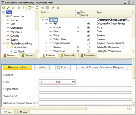
Fig. 594. Form editor
Multiple selection is available in the editors. In this case, only those properties that are present in all selected objects are shown in the property palette. Changes made in the property palette are applied to all selected objects.
To add form items, drag a form attribute to the item panel. The form item name will be similar to the attribute name. A path to the attribute will be set as form item data. You can change the item name later. The system automatically determines both the form item to display the attribute and its type if possible. Commands (both form commands and global commands) are added to the form in the same way. If the form attribute or the command is placed on the form, it has special grey marker to the right of its name.
If you add a form item by dragging it from another form, its Data property is not transferred. For all items transferred in this way, restore the correct paths to the data.
When you select a form item on the Items tab, the selected item is automatically highlighted in the preview window. If you select an item in the preview window, this item is automatically selected in the form item tree on the Items tab.
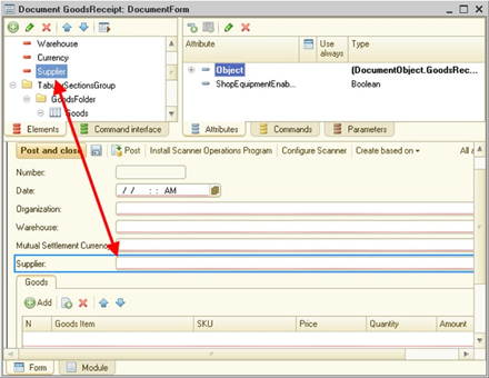
Fig. 595. Link between editors
You can select form items both in the item editor or in the preview window. The features available in the preview window are almost the same as in the item list. In particular, you can use item context menus, open the property window, drag items, and so on. If you select an item in the preview window, a border appears around the item. The border color depends on the item.
| Border color | Description |
|---|---|
| Blue | Highlights standard items |
| Orange | Highlights automatically created buttons and command bar submenus. Indicates that no settings (properties, position) can be made for this item |
| Gray | Highlights a parent item if the selected item cannot be highlighted in the preview window. For example, if you select the input field context menu in the item list, the input field is highlighted in gray in the preview window |
| Green | It is used when dragging items, displays an item to which you drag another item (for example, a table or a form group), and shows where the dragged item will be placed |
Clicking the window title in the preview window is similar to selecting the Form item on the Items tab. The opened context menu is also similar to the context menu of the Form item.
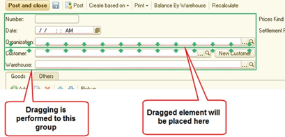
Fig. 596. Indicates dragging
To select a parent item (for example, a group that includes this field) for another item, click a subordinate item two times. This selection will work if the interval between clicks ranges from 1 to 2 seconds. If the time is shorter, the system may interpret the clicks as a double click. If the time is longer, it may treat them as separate actions. If several items are selected at the moment of the first click, the parent item is not selected.
To quickly navigate to related objects, use the Go to command. This command is located in the object context menu, in editors of items, command interface fragments, attributes, commands, and in the preview window. Using this command, you can, for example, quickly navigate from a form item (highlighted in the item list or in the preview window) to a form attribute displayed by this item. If you can navigate to several objects, a window with a prompt to select the desired object is opened.
Also the form editor allows you to quickly create (or navigate to) event handlers of a form item using the Events submenu of the item context menu.
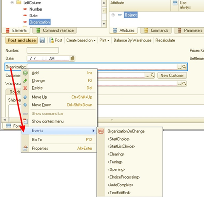
Fig. 597. "Events" menu
This menu includes all events available in the property window of a given form item. If the menu contains an event name in angle brackets, it means that the event handler is not defined. For example, for the Clear event of the Organization item in fig. 597. To create a handler, select the desired event. You will be navigated to the form module editor, and the necessary handler will be created.
If an event handler is already created for the event, the selection of the respective item in the Events submenu navigates you to the existing event handler in the form editor. For example, the OrganisationWhenChange() handler in fig. 597.
For a button, the Event submenu is not generated. The command to navigate to the handler of the respective command is located directly in the item context menu.
If you create a client handler, the system offers several options to do it:
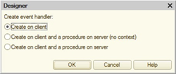
Fig. 598. Creating a client handler
The first option (Create on client) involves creating only a client event handler. The option Create on client and procedure on the server without context implies the creation of a client event handler, a non-contextual server procedure and a procedure call from the client handler. The last option differs from the previous one in that the server procedure is created as contextual. If in some client event handler it is not recommended to use contextual server calls (information about it is available in the Syntax Assistant), then the use of the latter option (with the contextual server procedure) is not possible. Deleting an event handler does not delete the server procedure (if it was created when creating the event handler).
When deleting an attribute (from the form attribute list), the system displays the following question: Do you want to delete the related items? If the answer is negative, the Data property is cleared for the related form items. If the answer is positive, form items related to the attribute to delete are deleted as well. If the item link with this attribute is not the main one (footer data, data displayed in the group header, and so on), then this item is not deleted, but the link with the attribute to delete is cleared. No matter what answer to the question about deletion is, commands of the form command interface related to the attribute to delete will be deleted.
If you delete form commands, you are also prompted to delete related items. If the answer is negative, form items are not deleted, but the Command item property is cleared. If the answer is positive, the buttons associated with the deleted command are deleted as well.
When designing forms, you need to see how the form is displayed in the desired interfaces (Taxi, version 8.2, mobile device). This can be done directly in the form editor.
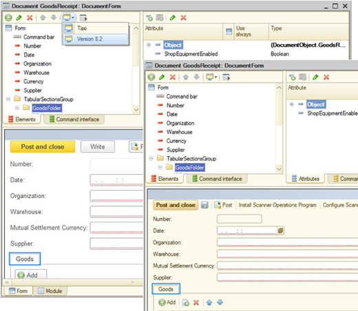
Fig. 599. Switching the interface mode
In fig. 599, you can see an example of how the display changes when the interface mode changes from the Taxi interface (upper left part of the figure) to the version 8.2 interface (middle part of the figure) and to the mobile device interface (right lower part of the figure). However, note that when the form is tested in theTaxi interface, some items are displayed in the version 8.2 interface.
Menu items that are displayed when clicking Interface option depend on the value of the Interface compatibility mode property. If this property does not allow you to use the Taxi interface, the Personal computer (Taxi) item is unavailable in the menu. Otherwise, the menu displays all three interface options as shown in fig. 599.
In special cases, you need to develop forms for which you can select the display scale (see Forms). If the form itself has the Scaling mode property set to Auto, the form editor allows you to select the scale to display the form preview.
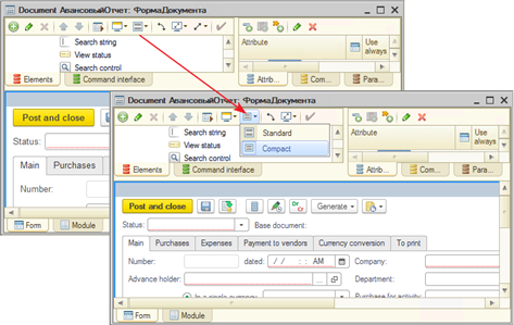
Fig. 600. Switching the scale mode
If the form should be used only in the Taxi interface and the compact display mode is not used, you can check in the form editor the form look if the custom scale is set.
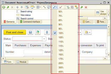
Fig. 601. Selecting a form scale
Changing the scale results in a corresponding change in the form in the preview window. To change the actual form scale, use the Scale form property.
Since 1C:Enterprise forms can be displayed on devices with different resolutions, during the development process you need to check how the form under development will look like in a certain resolution. To do this, the editor has the ability to quickly select the resolution for which the system places items in the form preview panel.
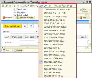
Fig. 602. Selecting the preview panel resolution
After a resolution is selected, the form is rebuilt as if the selected resolution is set in the preview panel. Physical dimensions of the form are not changed. The current monitor (where the form editor is displayed) is displayed on the first line of the menu and starts with the line Current monitor.
Applications can run on devices which screens can change their orientation (portrait or landscape orientation) during operation. To check the form look when changing the screen orientation the form editor allows to quickly emulate this operation.
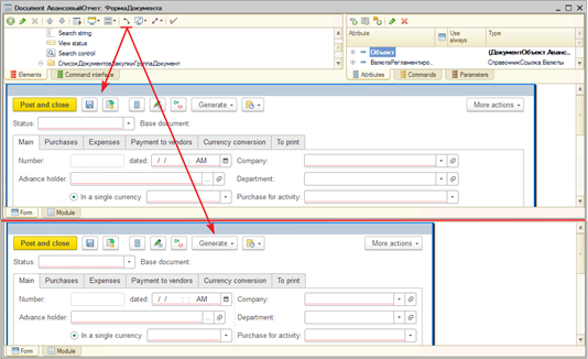
Fig. 603. Selecting a screen orientation
In fig. 603, you can see an example of how the form is displayed in resolution 1024x768 in landscape (upper part of the picture) and portrait (lower part of the picture) orientation.
When developing an application for a mobile device, it is necessary to preview the developed form look on a mobile device. To do this, click Interface option to select the Mobile device (Taxi) display mode.
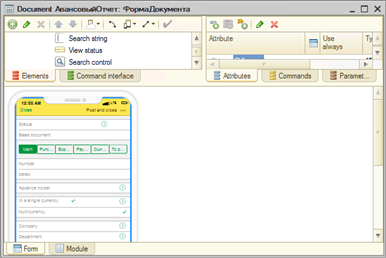
Fig. 604. Mobile devices
For the mobile device, you can select the orientation: portrait or landscape.
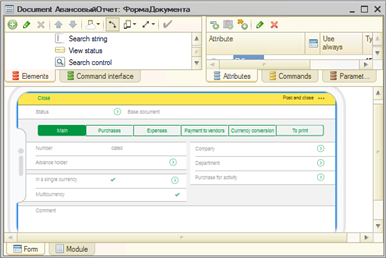
Fig. 605. Changing a mobile device orientation
In this sense the behavior of the editor is the same as for any other interface option.
The form editor also allows to select the display mode of the mobile device in the preview window. To do this, click Fit to window.
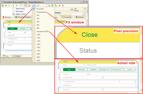
Fig. 606. Preview size
You can choose one of the several previewing options:
-
Fit window. The system scales the display to fit the mobile device screen into the preview window without the need to scroll it.
-
Actual size. The device size in the preview window matches the geometric dimensions of the target mobile device. To achieve the closest match, the display scale in the operating system should match the real DPI value of the monitor used.
-
Pixel precision. Each pixel of the preview window on the developer's PC is mapped to a pixel on the mobile device display.
-
Select any of the available form scale options.
If setting item properties when developing a form results in errors that can lead to issues with placing form items, you can display these errors using a special button.
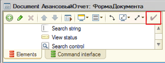
Fig. 607. Showing placement errors
To open the form for verification, press Ctrl + R. The form opens in a separate window. If the Mobile device mode is selected in the form editor, the form verification is unavailable.
When renaming or deleting an attribute, a parameter, or a form item, the system searches for the occurrences of the object to rename (delete) in the form module and in the entire configuration (if it is allowed in Designer settings, see Overall).
35.1.2. Role-based form customization
In the form editor, you can perform role-based customization of form behavior.
This feature is provided for the following properties:
-
View. Form attribute property. The absence of the view feature excludes the attribute from the form data (the attribute is not passed from the server). The user cannot change this setting.
-
Edit. Form attribute property. With the absence of edit feature the form element associated with the attribute is available only for viewing. Regardless of the state of this property, edit is unavailable if view of the form attribute is not available. The user cannot change this setting.
-
User visibility. Form item property. Specifies the default visibility of a form item. The user can individually change this property in the form settings editor.
-
Usage. Form command property. If a command usage is disabled, then all associated buttons are not present in the command interface. The user cannot change this setting.
Editors of all the above properties look and operate the same. Let us take a look at how you can use the editor, for example, on the View property.
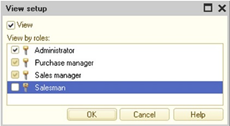
Fig. 608. Editing the "View" property of the form attribute
The View property (in the upper part of the editor window) defines the view state for each role, with its checkbox in the "third" state (the checkbox background is gray). Then, view states for all available roles are added "by OR". The result determines the final View property for the editable object.
35.2. Text editor
The 1C:Enterprise text editor provides all the basic text editing functions. The text editor provides operations with text blocks, search and replace functions, and highlight of syntax elements of program modules in color.
In 1C:Enterprise, the text editor is used in two modes: to edit text documents and as part of a form editor to edit text modules.
This chapter describes the features of the text editor when editing the texts of the modules.
Since all text editors in the Microsoft Windows operate similarly, this section describes the specific features of the 1C:Enterprise text editor.
Note. Note. The text editor does not allow you to enter characters that are invalid in XML version 1.0 (http://www.w3.org/TR/xml/). When you try to enter such character, it is simply ignored. When such characters are inserted from the clipboard, they are skipped and do not appear in the inserted text.
For the list of keyboard shortcuts available in the text editor, see the application help.
35.2.1. Editing modules
Modules are edited during creation the configuration object form, as well as in the development of modules (application module, external connection module, common modules, application object modules).
When a form is created, the text editor operates as an integral part of the form editor. To call it click on the Module tab in the form editor window; otherwise, the text editor is called in a separate window. To open a managed application module, an external connection module, a session module, and a ordinary application module, right-click the configuration name (the topmost line of the configuration tree) and select the appropriate item in the context menu.
To edit an object module, select the object and select the Open object module item in the context menu.
To edit the manager module (if the object has such module), select the object and select the Open manager module item in the context menu.
To edit the command module, double-click the command or select the Open command module item in the context menu of the command.
To edit a common module in the Configuration window, in the General – Common modules branch, select the required module and select the Open module item in the context menu.
You can edit modules the same way you edit text documents. You can use all the text editor features.
This section describes the specific modes of the text editor available when editing modules.
35.2.1.1. Syntax highlighting
To easily edit module texts, you can use the text editor function to highlight 1C:Enterprise language items, such as keywords, constants (not of configuration objects) of various types, operators, comments, and so on. You can set colors for different syntax structure types in the Parameters window. To open it, click Service – Parameters (for information about settings of the text editor parameters, see Modules).
Built-in function names are not highlighted (the color matches the ID color).
In the general case, when a text editor is called to edit the text of a module, this function is automatically enabled. However, in some cases, the module text may be located in an external text file. Then, when opening such a file, Designer does not recognize the module and considers it as a plain text document. In this case, when editing text, highlighting the syntax structures by color and automatic formatting the text of the module are unavailable. You can indicate to Designer that the editable text is a module, not a text document. To do it, use the Text – 1C:Enterprise language menu item as a switch.
When it is turned on (a check mark appears in the menu to the left of 1C:Enterprise language text), the text editor reads the module text loaded into it and highlights the found syntax structures with color.
Fig. 609. Color highlighting is enabled
If this mode is enabled when editing a plain text document, the test is displayed using font set for the module text in the Designer (the menu item Tools Options, the Texts tab, the Font attribute).
By setting the parameters of the 1C:Enterprise you can turn off the mode of highlighting syntax structures. In this case the choice of the 1C:Enterprise language item does not enable highlighting of the module syntax, but only the module font and tab positions are set.
If syntax highlighting is turned off, the colors of the operating system are used to display text.
35.2.1.2. Grouping
When modules or text documents are viewed in the 1C:Enterprise language mode, some syntax structures are automatically combined into groups. These structures include If … Then … EndIf, While … Do … EndDo, Procedure … EndProcedure and so on.
The text groups improve code readability and make it much easier to copy or move syntactic structures as separate text units.
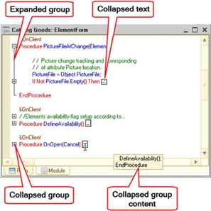
Fig. 610. Groupings in the text editor
You can collapse and expand a group with the mouse. To do this, simply click the left mouse button on the group marker.
If you press Ctrl at the same time, you also collapse and expand subordinate groups (conditions, loops, and so on).
To display collapsed text, hover the cursor over the marker as shown in fig. 610. If the text of the group is large enough, then only its beginning is displayed.
During the development, it may be necessary to group the module fragments. For example, you may need to select logically related procedures and functions, or select fragments of an algorithm within a single procedure or function. To do this, use preprocessor command #Region … #EndRegion.
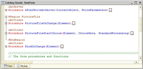
Fig. 611. Line grouping
All lines bounded by preprocessor directives can be collapsed in the module editor (like other 1C:Enterprise language constructs). Each region must have its own name formed according to the rules of the 1C:Enterprise language. In the example shown in fig. 611, the name of the region is ImageFile. Regions can be nested, but cannot intersect with other syntactic constructs of the language. The following are correct and incorrect examples of the use of regions:
// Correct use of
region
#Region Correct
…
#If Client Then
…
#EndIf
…
#EndRegion
// Nested regions
#Region CalculationAlgorithm
…
#Region Step1
…
#EndRegion
…
#Region Step2
…
#EndRegion
…
#EndRegion
// Incorrect use of
region
#Region Incorrect
…
#If Client Then
…
#EndRegion
…
#EndIf
// Incorrect use of region
#Region Incorrect
Procedure GetData()
…
#EndRegion
…
EndProcedureA region can be described by a comment before the region (#Region). This comment can also be grouped.
Using keyboard commands, you can easily manage the status of groups.
| Keys | Description |
|---|---|
| Ctrl + Num- | Collapses the group (the cursor can be anywhere in the group) |
| Ctrl + Num+ | Expands the group (the cursor should be in the first line of the group) |
| Ctrl + Shift + Num- | Collapses all groups |
| Ctrl + Shift + Num+ | Expands all groups |
| Ctrl + Shift + R | Renews groupings |
When coding a module at the time the developer completes a syntactic structure, the groups are automatically created for all syntactic structures of any nesting level. Updating groupings is performed using the menu item Text – Grouping – Update grouping or automatically when saving the code according to the group display setting.
The first level is the description of procedures, functions and regions, the second level is the syntax structures nested only in the body of a procedure or function, but not in the body of other syntactic structures. The mode of the group display can be customized. About setting the mode, see Setting group parameters.
35.2.1.3. Using bookmarks
When coding a module, the developer can mark any text line to be able to go to the marked fragment quickly later. This mark is called bookmark.
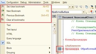
Fig. 612. Bookmarks in text
To set a bookmark, use the command Text – Set / Clear bookmark. The bookmark is marked with a color mark in the column to the left of the module text.
It is also possible to go to the next bookmark (the Text – Next bookmark command) or previous bookmark (the Text – Previous bookmark command), and also to delete all bookmarks set (Text – Clear all bookmarks).
A list of all the bookmarks set can be seen in a specific list using the Edit – Bookmark list command.
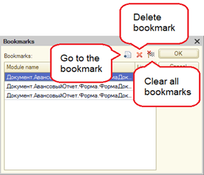
Fig. 613. List of bookmarks
Using this list, you can go directly to the desired bookmark, and delete specific bookmark or all bookmarks at once. Please note that you can go to a bookmark only using a special button. When you press OK, it does not navigate you to the marked bookmark.
Note that the system saves the bookmark list between sessions when you edit documents and use Designer.
35.2.1.4. Formatting modules
1C:Enterprise text editor includes a number of modes that facilitate the module development.
35.2.1.4.1. Formatting syntax structures
The best practice to write modules is to use the syntax indentation, that is, to highlight 1C:Enterprise language control structures with leading spaces (tabs). See an example of the module fragment below.
Procedure NextElement(Catalog, Selection)
While True Do
If Selection.Next() = False Then
Selection = Catalog.Select();
Continue;
Else
Break;
EndIf;
If Selection.IsFolder Then
Continue;
EndIf;
Return;
EndDo;
EndProcedureIn this fragment, the module lines located inside the structure operators If ... Then ... EndIf and While ... Do ... EndDo, are shifted to the right to emphasize their "nesting". Module text formatted using syntax indentation is easier to read and easier to debug.
1C:Enterprise text editor provides functions for automatic formatting of 1C:Enterprise language control structures. To set up automatic formatting in the system settings mode (the Tools – Options item of the main menu in Designer, the Modules tab), you can select one of two types of indentation.
The syntax indentation performs automatic formatting of the module text, shifting the text located inside control structures of the type If ... Then ... EndIf and While ... Do ... EndDo and similar to the right. To shift test the necessary number of tabs are added to the beginning of the lines.
"Ordinary" indentation automatically aligns the line text to the left border of the previous line.
If auto-indent is disabled, no additional characters are added to the text.
In addition to automatic formatting of the module text, you can also format already entered text during the coding. To do this, select the block of text that you want to format, and select the menu item Text – Block – Format. The test editor analyzes and formats the text by shifting the content of each syntactic construction to the right with the standard tab indent, regardless of the original indents (leading spaces). Tabs are set into blank lines in accordance with the syntax.
A text block can also be shifted as a whole to a tab position to the right or to the left. To do this, select the text block and use the Text – Block – Shift right (Text – Block – Shift left) command.
1C:Enterprise text editor automatically removes spaces at the ends of lines. This is done when writing a module.
35.2.1.4.2. Inserting/deleting comment marks
When debugging modules, you might often need to "disable" some module lines temporarily so that they are not executed when the system runs. For this, convert such lines into comments. To do it, add the "//" comment mark to the beginning of the lines. Later, to "enable" the commented lines again, the comment mark is deleted.
To disable (and later enable) large module fragments, you can automatically set comment marks for all lines of the selected block or for the current line (you do not need to select it).
To do this, select the block of text or set the cursor to the desired line and select the Text – Block – Add comment (Text – Block –Delete comment) menu item.
When deleting a comment, if there are several comment marks in the beginning of the line, then only one mark is deleted.
35.2.1.4.3. Inserting/deleting line break characters
When writing string constant values, use the "|" line break character.
The text editor allows you to easily add or remove this character in the selected lines.
To insert/delete the line break character for all lines of a selected block or for the current line (you do not need to select it), specify a region and click Text – Block – Insert line break or Text – Block – Delete line break.
The line break character is inserted into the first significant (not a space or a tab) position of each line.
35.2.1.5. Navigating to module procedures and functions
If a module contains a lot of procedure and function descriptions, you can use the procedure search mode available in 1C:Enterprise text editor.
Click Text – Procedures and functions to open a window with a list of all procedures and functions of the editable module.
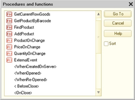
Fig. 614. Procedure and function list
The names of the procedures and functions are listed in the order in which they appear in the module. If the Sort checkbox is checked, the list is sorted alphabetically.
Names of procedures and functions already placed on the form are marked by icon to the left of the name.
To navigate to the desired procedure or function, select its name in the list and click Go to.
The list of procedures and functions shows the names of events, which handler procedure is not yet created, in angle brackets. The created procedures and functions are marked by icon before the name (P() and F(x), respectively). The composition of the events that can be processed is determined by the type of object and the type of the form, as well as by the composition of the controls located in the form. When you select such line, a predefined procedure text is added to the module, and a link to this procedure is added to the respective event of the Events category.
Note. Important. Creating event handler procedures defined by the system for a particular module must be performed in the property palette for the corresponding form in the Events property category, or using the Procedures and functions window, or from the field in the Procedures and functions list. With simple copying event handler procedures from other modules, the event handlers for this form will not be initiated by the system, and the copied procedures will not be called to handle events.
When you move the cursor to the module line, the name of the current procedure or function is displayed in the procedure selection field of the Module toolbar (the Procedures and functions command). Using this list, you can also navigate to the desired procedure or function.
To go to a procedure, a function, or a variable, just hover the cursor over their name and press F12. Such navigation is possible only for procedures, functions and variables located in the same module, or to exported procedures, functions and variables of the application module, common modules and object modules. To return to the point from which you navigated to the definition, press Ctrl
- "-" (next to the "=" key).
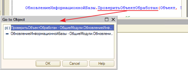
Fig. 615. Go to the definition
If the entered expression consists of parts defined in different places of the configuration, a list of such objects is displayed before the transition to select desired destination. You can go to the definition of a variable, to the definition of a metadata object with type of the current expression, or to the definition of a procedure or function used in the expression (for example, in a object module with type of this expression).
For example, for the expression Dir.FindByCode(), where Dir is defined as the Currencies catalog, pressing the F12 key displays a list of navigation to the definition of the variable Dir and to the definition of the metadata object Catalogs – Currencies in the configuration objects tree.
It is possible to search for places where a variable, procedure or function is used. The search is performed across the entire configuration. To perform such search, place the cursor "inside" the name you want to find and call the Find usage command of the text editor context menu (or press Alt + F12).

Fig. 616. Find usage
After the search is completed, a window opens with search results. From this window you can go to the corresponding module by double-clicking the desired line.
The first character in the search results describes the accuracy of the definition of each found usage. The "i" character means that the usage is completely and unambiguously defined. The "!" character means that the usage of a variable, a procedure, or a function is not clearly defined.
35.2.1.6. Context help for module text input
1C:Enterprise text editor provides a tool for context input of expressions using system objects, their properties, methods, procedures and functions, object names defined in the configuration, also variables, procedures, and functions defined in common modules, application modules, and form modules. The list includes predefined items of catalogs, charts of accounts, charts of characteristic types, and charts of calculation types.
The context help list can include text templates and keywords.
Note. Note. The text context help is not supported by the system for text documents with the 1C:Enterprise language property set.
Items are entered from the list displayed as a context menu at the current cursor position (considering how close the screen borders are located).
To call the list, press Ctrl + <Space key> or Ctrl + M when entering an expression. The list will also be called automatically after you enter a dot "." after the expression, which is an object with properties and/or methods (when context help is enabled, see Context tooltip settings).
The list content depends on the module execution context and the text entered previously. See "General language description" in the 1C:Enterprise language help.
At the initial stage, when the text has not yet been entered or only the initial characters of the expression have been entered, the list content is determined by the execution context.
The list is presented in the form of text lines sorted alphabetically.
If when list is opened a text fragment is entered, then the list is positioned on the first line, the name of which includes the entered or selected text as much as possible (from the beginning of the name). If the typed text is not contained in the lines of the list, then the list is positioned on the line in which the typed text is most represented.
With the list open, you can continue typing. In this case, the list is sequentially positioned on lines that match the typed text.
The list can be viewed in a standard way. When you press Enter, the selected line content is transferred to the module replacing the selected or typed text.
Note. Note. When a text is transferred to the module, the method parameters are not inserted and the context of the client application is used.
In the left part of the lines there are icons indicating the type of object and the type of its location.
| Icon | Object |
|---|---|
| line (black) | · Global context property · System value sets · Enumerations |
| line (green) | · Object properties of universal value collections · Interface object properties · Applied object attributes · Predefined items |
| line (blue) | Module variables to export |
| line (red) | Local module variables |
| P() (black) | Global context procedures |
| P() (green) | Procedures of interface and applied objects |
| P() (blue) | Procedures to export of other modules |
| P() (red) | Local module procedures |
| F() (black) | Global context functions |
| F() (green) | Functions of interface and applied objects |
| F() (blue) | Functions to export of other modules |
| F() (red) | Local module functions |
| Colored lines | Keywords (If, Do, Try, and so on) |
| Picture of templates | Text template |
Text templates are only included in the list if they have the auto-replacement string specified.
When you enter a text or select it from the list, if the text forms an expression with properties or methods available, once you type "." (dot), the list of available properties and methods for this expression is displayed automatically.
For example, when you enter "Catalogs.", a list is displayed containing names of all catalogs described in this configuration. After selecting a specific catalog and entering a dot ".", the list is displayed again, However, now it contains names of procedures and functions for this catalog, and predefined catalog items. When choosing a method that returns a value of a certain type, which in turn has properties and methods, the context input can be continued (you must enter the opening and closing brackets at the end of the name). The context help list contains only a possible set determined by the type of the entered expression.
For module variables, you can also use the context help feature. When declaring variables, note the following feature: to ensure that explicitly declared variables are included in the context help, each variable must be marked by its ownVar operator (see Statements and syntax structures). Otherwise, the context help displays only the first variable from each Var operator. The following example displays all declared variables:
Var TemplateName;
Var HideDiscount;
Var MutualSettlementsBalance;In the following example, the tooltip displays only one variable, which is TemplateName:
Var TemplateName, HideDiscount, MutualSettlementsBalance;You can use the context help when entering the New operator and for variables created using the New operator.
You can use the context help when entering various keywords (for example, If, For, Do, and so on). Keywords are included in list called in the standard way by pressing Ctrl + <Space key> (Ctrl + M) at any stage of typing words.
You can customize the display of the keyword list (see Context tooltip settings).
If for any variable or method, this list consists of only one line, then pressing Ctrl + <Space key> (Ctrl + M) immediately insert this line.
Context help also allows you to display a list of method parameters and its type. Parameters are displayed for both global context objects and 1C:Enterprise language objects, as well as for application methods, which description meets certain requirements. For 1C:Enterprise language operators, the context help for parameters is not displayed. Parameters are displayed after you enter "(" or "," (you can customize it; for more information, see Context tooltip settings) or after you press Ctrl + Shift + <Space key> (Ctrl + Shift + M) after the "(" character of a procedure or function call.
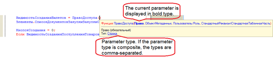
Fig. 617. Context help for parameters
If a method has several syntax options, the first option in the order is displayed. However, before the syntax description, you will see the up and down arrows allowing you to switch between various options. You can also switch between options, pressing Ctrl + <Up arrow> and Ctrl + <Down arrow>.
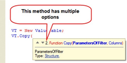
Fig. 618. Several syntax options in the context help for parameters
Under the parameter description, the type of value that can be passed to this parameter is displayed. If the value can be of several types, these types are listed separated by commas. The type name is a hyperlink that you can click to open the Syntax Assistant (see Syntax Assistant) with the information about the type. The context hint for parameters is closed after entering the ")" symbol or pressing the Esc key when the window of the context hint for parameters is opened.
In order to the context hint shows the description of the parameters and their types for the methods of the application, a comment must be placed before the method according to certain rules. In general, the description of a procedure or function consists of the following sections:
-
Description. Contains a brief description of the purpose and/or principles of a procedure or a function. It can be the only section for functions without parameters.
-
Parameters. Describes parameters of a procedure or a function. If there are no parameters, the section is skipped.
-
Return value. Describes a type and content of the function return value. This procedure is unavailable for procedures.
-
Example. Contains an example of how to use a procedure or a function.
An overall format of a comment is as follows:
= [<HeaderSection>]
[<ParametersSection>]
[<ReturnValueSection>]
[<ExampleSection>]
<NewRow> = Beginning of module line
<Name> = 1C:Enterprise language ID
<Type> = <Name> | <Name>"."<Name>
<TypesList> = <Type>{","<Type>}
<TextLine> = Arbitrary text without line break
<Text> = <TextLine> {<NewLine> <TextLine>}
<HeaderSection> = [<Text>]
<ParametersSection> = <NewString>
("Parameters:") {<ParameterDescription>
{<TypeDescription>} }
<ParameterDescription> = <NewString>
<Name> [" " <TypesList>] " " [<Text>]
<TypeDescription> = <NewString> "
" <TypesList>] " " [<Text>]
<ReturnValueSection> = <NewString>
("Returns:") <ValueDescription>
<ValueDescription> = <NewString>
[<TypesList> " "] [<Text>]
<ExampleSection> = <NewString>
("Sample:") <NewString> <Text>As a result, a comment before a procedure or a function designed in accordance with the described format causes the method parameter context help to correctly show the help for the application method.
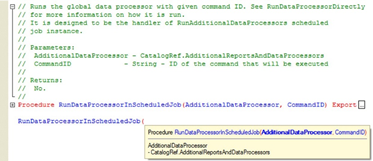
Fig. 619. Context help for application method parameters
So, the context help feature of 1C:Enterprise text editor provides a method to quickly and correctly type module texts.
35.2.1.7. Refactoring tools
35.2.1.7.1. General information
Refactoring is the process to review 1C:Enterprise language code to improve the code readability and its general internal structure, maintaining its initial meaning and behavior. Designer offers several built-in tools that can help with the refactoring of the application. These tools can be accessed in the Refactoring submenu of the context menu of the 1C:Enterprise language text editor or in the Text menu of the Designer main menu in the same name submenu.
Now we consider the refactoring tools in more detail. We will use the following terms:
-
Block is a line set between the following keywords: Then…EndIf, Then…Else, Then…ElseIf, Do…EndDo, Try…Exception, Exception…EndTry, Procedure…EndProcedure, Function…EndFunction;
-
Terminal call is the last statement executed by 1C:Enterprise language method:
-
It is located before the EndProcedure, EndFunction, or Return keyword.
-
It is the last statement in the recursive-last block of the method statements.
-
-
Asynchronous method is a method that can be used in call chains using notification handlers.
35.2.1.7.2. Extract fragment
This command converts the selected syntactically complete fragment of code into a separate procedure or function. The type of extracted fragment depends on the final scopes of the variables of the parent method and the structure of the fragment.
If the extracted fragment can act as a source in an assignment operator, the fragment is extracted as a function. In addition a function can be extracted based on a fragment initializing a single variable, which is used in the rest of the parent method. In other cases, the fragment is extracted as a procedure.
If the variables of the extracted fragment are used in the remaining part of the parent method, these variables are passed to the extracted method as parameters, with their preliminary initialization or declaration (if necessary).
If the parent method (from which the fragment is extracted) is preceded by a compilation directive (see Compilation directives), the extracted method is also preceded by the same compilation directive.
The code of the new method is placed immediately after the code of the parent method (from which the fragment is extracted) and is formatted properly (see Formatting syntax structures).
35.2.1.7.3. Rename
This command allows you to change the name of a variable or a method. If the reference to the export renamed variable or method cannot be determined unambiguously, the renaming is not performed and a list of the use of the variable or method is displayed.
For export variables and methods of the form module, the tool analyzes if the identifier within the whole configuration is unique and if there are no its synonyms among the methods and properties of the platform. If these conditions are met, the user is offered to replace the identifier globally in all places of its possible use.
Renaming a method parameter does not change the name of this parameter in the comments, including the description of the method (created in any way).
When renaming methods, the application additionally checks the method name is transferred as a string literal:
-
Into object constructors:
-
Action
-
NotifyDescription
-
-
Into global context methods:
-
SetAction()
-
AttachDataChangeHandler()
-
DetachIdleHandler()
-
AttachIdleHandler()
-
AttachNotificationHandler()
-
When you rename a handler method in a form module, it automatically replaces the reference to the renamed handler in the respective form item properties and commands. When you rename a handler method from the form item or command property palette, all calls to the given handler (if any) are automatically renamed in the program code.
35.2.1.7.4. Create method description
The command creates a comment before declaring a method. The comment will be used for context help when entering a module text (see Context help for module text input).
35.2.1.7.5. Create notification handler
This command simplifies the use of asynchronous 1C:Enterprise language methods (see Synchronous and asynchronous operations). The command becomes available after the method name and the opening parenthesis are entered (the cursor must be placed on the method name). The further behavior of the command is equivalent to the behavior of the refactoring command Convert call, with the exception of renaming the method to which the refactoring command is applied. If the method already passes object of the type NotifyDescription, the user is asked to confirm the command execution to continue.
35.2.1.7.6. Using legacy synchronous calls
General information
In this section, you can read about refactoring commands that allow you to rework the application code to use asynchronous calls instead of synchronous calls (see Synchronous and asynchronous operations).
Convert call
The command replaces trivial and simple cases when synchronous methods are used with similar asynchronous methods (see Synchronous and asynchronous operations).
A case is considered trivial if its transformation affects only one method and does not require operations other than selecting this fragment. The modal call is considered trivial in the presence of the following conditions:
-
The call is located in a procedure that is not called from other procedures and functions, with the exception of recursive-terminal calls. In the analysis for terminality, the belonging of the calling methods may be uncertain. If this is not observed, the case may be simple or require conversion to an asynchronous procedure (see Convert to asynchronous procedure).
-
The call is located outside the cycle blocks, except for the case of the Abort or Return statements following on the same nesting level.
-
The call is outside the exception catch blocks.
-
The nesting level of a modal call does not exceed 2, with the exception of the recursive-last block statements. You can reduce the nesting level of a modal call using the fragment extraction command (see Extract fragment). If the extracted fragment contains the Return operator, then you should extract such fragment using the command for extraction fragment into asynchronous procedure (seeExtract to asynchronous procedure).
-
After the modal dialog box is called, procedure parameters do not change either in the procedure or in one of the nested calls.
A case is considered simple if it does not satisfy only the first triviality condition and requires only to convert a procedure or a function with a synchronous call into an asynchronous form. When such synchronous call is found and such conversion is possible, the system automatically offers to convert it into an asynchronous procedure (see Extract to asynchronous procedure).
A conversion result can be:
-
Initial procedure when a synchronous call is replaced with an asynchronous call.
-
Notification handler procedure. If a synchronous call is the last statement of the parent block, the user decides whether to create an empty procedure.
-
Fragment-ending. A common code for the initial procedure and the notification handler procedure when the call to the synchronous method is not included in a single sequence of code execution.
If the case does not meet one or more requirements, the user can perform partial conversion: the maximum syntactically correct code snippet is extracted to the notification handler procedure and an exception is thrown after the asynchronous method call. A comment is added to the module code with a description of the reasons for non-compliance.
Convert to asynchronous procedure
The command is used to convert a method to a form that allows to use this method in asynchronous calls. The conversion affects all already existing call sequences involving the selected method, but the methods that are called from the converted method are not changed. This command should be used when it is necessary to convert modal calls (one or several) within a function or procedure called from other methods. After executing this command, convert the modal call into its blocking variant using the modal call conversion command (see Convert call).
Conversion of methods that alter their reference parameters is not supported in order to prevent hard to find logical errors. In addition, the system does not support conversion of call sequences containing a direct call to the procedures for handling events of forms and metadata objects because the list of their formal parameters is strictly fixed. If the conversion involves multiple modules, the user is asked for additional confirmation.
Let us consider an example of conversion a call to an asynchronous form.
Note. Note. This example is only to demonstrate the conversion process and is not an example of any real activity.
Suppose a form module contains the following call chain:
&AtClient
Var ProcedureCalled;
&AtClient
Var FunctionCalled;
&AtClient
Procedure FormCommand
(Command)
ProcedureCalled = False;
FunctionCalled = False;
CallProcedure();
EndProcedure
&AtClient
Procedure CallProcedure()
Result = CallFunction();
ProcedureCalled = True;
EndProcedure
&AtClient
Function CallFunction()
ShowDialogBox();
FunctionCalled = True;
Return True;
EndFunction
&AtClient
Procedure ShowDialogBox()
DoMessageBox("Warning!");
EndProcedureConvert the ShowDialogBox() method.
The call chain starts when from the form command handler (procedure FormCommand()) the procedure Procedure1() is called. The actions performed in the CallProcedure() and CallFunction() methods in this example simply demonstrate the presence of some program code after calling another procedure.
The call chain looks as follows: FormCommand() -> ExecuteProcedure() -> ExecuteFunction() -> ShowDialogBox().
As a modal dialog box is called at the very "bottom" of the call stack, the entire method call chain must be converted to asynchronous format. The DoMessageBox() method can be replaced with an asynchronous analog, and for other procedures this analog will be created by the system.
We perform the conversion of the ShowDialogBox() method and refuse the suggestion to create empty notification handlers. The result is the following code:
&AtClient
Var ProcedureCalled;
&AtClient
Var FunctionCalled;
&AtClient
Procedure FormCommand
(Command)
ProcedureCalled = False;
FunctionCalled = False;
CallProcedure(Undefined);
EndProcedure
&AtClient
Procedure CallProcedure(Val Notification)
Result = Undefined;
CallFunction(New NotifyDescription("CallProcedureFinal", ThisObject, New Structure("Notification", Notification)));
EndProcedure
&AtClient
Procedure CallProcedureFinal(Result1, AdditionalParameters) Export
Notification = AdditionalParameters.Notification;
Result = Result1;
ProcedureCalled = True;
RunCallback(Notification);
EndProcedure
&AtClient
Procedure CallFunction(Val Notification)
ShowDialogBox(New NotifyDescription("CallFunctionFinal", ThisObject, New Structure("Notification", Notification)));
EndProcedure
&AtClient
Procedure CallFunctionFinal(Result, AdditionalParameters) Export
Notification = AdditionalParameters.Notification;
FunctionCalled = True;
RunCallback(Notification, True);
Return;
EndProcedure
&AtClient
Procedure ShowDialogBox(Val Notification)
DoMessageBox("Warning!");
RunCallback(Notification);
EndProcedureDuring the conversion, the call of the DoMessageBox() modal call in the ShowDialogBox() method was not changed as modal call replacement is not in the scope of the described command. It should be noted that all converted methods now receive a notification description as an input parameter. Now the call chain looks as follows: FormCommand() -> ExecuteProcedure() -> ExecuteFunction() -> ShowDialogBox() -> ExecuteFunctionEnd() -> ExecuteProcedureEnd(). The methods with the suffix Final are called by sending notifications.
Extract to asynchronous procedure
This command converts the selected syntactically complete fragment of code into a separate procedure or function, converting in addition the selected method to asynchronous form.
Find module calls
The command lists the use of legacy synchronous methods in the current module.
Convert module calls
The command converts all trivial (seeConvert call) use cases of legacy synchronous calls into their asynchronous versions (see Different approaches to modality). Conversion is performed within the current module.
Analysis of legacy synchronous configuration calls
This command (Main menu – Configuration – Refactoring – Analysis of legacy synchronous configuration calls) look through the all configuration to search for legacy synchronous calls and to analyze the possibility of their conversion. If conversion is impossible, the system indicates the reason.
During the analysis of legacy synchronous calls, the following features of the application are taken into account:
-
All modules that can be executed on the client application side are analyzed.
-
The analysis of modules that cannot be executed on the client application side is not performed:
-
Web service modules
-
HTTP service modules
-
Common modules that can only be executed on the server side
-
Common modules that can only be executed via external connection
-
-
Procedures and functions preceded by the following compilation directives are analyzed (see Compilation directives):
-
&AtClient
-
&AnClientAtServer
-
&AnClientAtServerNoContex
-
-
Text fragments of procedures and functions that are enclosed in the following preprocessor instructions are analyzed (see Preprocessor commands):
-
Client
-
ThinClient
-
WebClient
-
ThickClientManagedApplication
-
ThickClientOrdinaryApplication
-
The Display methods of objects whose type cannot be defined checkbox tells the system that the search results should include methods that are synchronous, but it is impossible to unambiguously determine the object for which they are called.
If the Convert modal calls that are found checkbox is selected in the search settings dialog box, only trivial synchronous calls are converted (see Convert call) and the operation results are displayed.
35.2.1.8. Module syntax check
You can check the module being edited for compliance with 1C:Enterprise script syntax. To check the syntax, click Text – Check syntax.
Syntax check is performed in the following order:
-
Common modules
-
Managed application module
-
Object module
-
Form module
Modules are checked if the module was not yet checked or was modified.
When checking a specific module, only those modules that are in the list before this module are checked. For example, when checking an application module, only common modules are checked. An external connection module is checked only when it is edited.
If there are errors, their list is displayed in a message window specifying the full address of the location and the description of the error. If you move the cursor over an error message, the pointer turns into a magnifying glass. To navigate to the module line that caused the error, double-click the error message. If the module containing the error is not open, it is opened automatically.
If no errors are detected, a message about the absence of errors in the module is displayed in the message window.
You can enable the automatic verification of the module in the configuration mode of Designer (Tools – Options, the Modules tab, the Check tab, the Check automatically attribute). In this case, if the module has been changed, then at closing the module window or at saving the configuration as a whole, the syntax check of the module is performed. The automatic check mode is convenient when debugging any configuration element.
For full syntactic control of all configuration modules in one pass, select the item Configuration – Module check.
When fixing errors in modules, you can get a tooltip for 1C:Enterprise language. To do it, call Syntax Assistant and find a description of the desired language element (see Syntax Assistant).
A hint on a specific language element (operator, procedure, function, property, method) can be obtained by placing the cursor in the module on this language element and pressing Ctrl + F1 key shortcut. Syntax Assistant displays the description for the selected element of the 1C:Enterprise language.
35.2.1.9. Configuration modules access restriction
For some modules you can set an access password. The main password purpose is to protect copyright for configuration developers.
When setting a password, the following restrictions are applied:
-
Managed application module is not protected.
-
Form modules are not protected.
-
Command modules are not protected.
-
Modules that include preprocessor directives are not protected.
-
Client common modules operating in managed mode (thin client, web client, and managed mode of the thick client) are not protected.
35.2.1.9.1. Setting access passwords
To set a password, open the required module and select the command Text – Set password. The item is available if the module is opened for writing.
If the module contains preprocessor directives, the program displays a warning: Protected module must not contain preprocessor directives. Continue? If you click the No button, the password is not set. If you press the Yes button, the password setting becomes possible, and it is assumed that in this process the directives are deleted. If the directives are not removed, then in 1C:Enterprise mode the methods of such a common module will be unavailable (error Object method <Method name> not found).
Dialog box for entering the password is displayed.
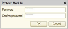
Fig. 620. Setting a module password
You need to enter a password and repeat it. To set the password, click OK, to cancel it, click Cancel.
35.2.1.9.2. Opening protected modules
If an access password is set for the module, then when you try to open the module, a password input dialog is displayed.
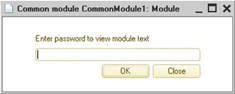
Fig. 621. Opening a module with the set password
If the entered password is correct, the module opens. If the entered password is wrong, the warning Incorrect password is displayed and the module does not open.
35.2.1.9.3. Changing passwords
To change a password, open the required module and select the Text – Set password command. Dialog box for entering the password is displayed. You should enter the old password. If the entered password is correct, the dialog box for entering a new password is displayed (see Setting access passwords).
To remove the password, you need to clear the password fields and, without entering the password values, click the OK button.
35.2.2. Editing text templates
If the Text Document is selected as the template type in the template designer, the text editor is opened in the text template input mode.
Text template editing mode is also available for text documents with the Text template extension set.
35.2.2.1. Text template format
The whole text of the template is divided into areas. Areas must follow each other and cannot intersect or be included in each other. In the template text the areas are highlighted as follows:
#Area XXXXX
#EndOfAreaWhere XXXXX is an area name.
You do not need to specify the end of the area. The declaration of the area beginning means the end of the previous area.
To store area options in several languages, you can specify a language code after an area name.
#Area Header1 RU
#EndOfArea
#Area Header1 EN
#EndOfAreaIf the language code is not specified for some variant of the area, then this variant of the area is returned when the language code that is not specified in any variant of the area descriptions is passed to the GetArea() method.
Each area consists of service and text parts.
#Area XXXXX
[service part]
[text part]
#EndOfArea35.2.2.2. Area service part
The service part of area has no explicit boundaries. It includes all the lines from the beginning of the area that start with the special character "#". The service part describes the text template fields used within the area. If service part is not necessary, it may be absent.
The control structures of the text template are highlighted in color.
35.2.2.2.1. Service area structure
The service part of the area consists of declarations of some common parameters of the area and descriptions of the field formats included in the area. All descriptions made in the service part of the area are valid only within the region. If the field format is described in a certain area and this field is found in another area without a format description, the default format is used for it in that another area.
At the beginning of the service part of the area, the keyword of the common area #ReplaceChar A B may follow. It is used to replace characters within the lines of the area:
-
A is a character to replace.
-
B is a character replacing the A character.
The characters must be enclosed in single quotes.
For example, if you write #ReplaceChar "@" "#", then inside the lines the "@" characters not in the field names will be replaced with "#".
It makes sense to use this keyword in cases where the design of the lines of the template should include the # character (its direct use would indicate that the text is a service text).
35.2.2.2.2. Field descriptions
The replacement description is followed by a description of the field formats used in the area.
To create a field, use the #Field FFFF keyword, where FFFF is a name of the field whose format is described.
Then the following lines contain keywords to describe the field. The field description is active until the beginning of the next field description.
#Align {Left | Right | Center | Justify} indicates the alignment of the field within its character space.
#Field OperationMode
#Align Justify#Format <Format string> specifies the format string for the field output.
#Field Date1
#Format "DF=dd.MM.yy"
#Field Tm1
#Format "ND=4; NFD=0; NDS=."#Block <Parameter> indicates that the space reserved for the field must be filled with the "#" characters. If <Parameter> = True and the contents of the field does not fit in the allotted space, the rest space is filled.
#Field ReportSummary
#Format "ND=18; NFD=2; NDS=."
#Block True35.2.2.3. Area text part
The text part of the area consists of the lines of the text template. It begins after the last line of the service part of the area, and continues to the area end. Inside the text template lines, you can specify a field name: [FFFF].
The number of spaces reserved for the field corresponds to the number of spaces indicated by the brackets (including brackets). If the field size is one character, one bracket is allowed. Example:
![Name ]! [Code ]! [Description ] !If the field name is shifted to the left bracket, it is considered that the field has left alignment, and if the name is shifted to right bracket, then the right alignment assumed. If there are spaces to the left and right of the field name, it is centered within the character space of the field.
If the field name is greater than the character space allocated for the field, the field name is indicated using the Fields keyword.
Example:
#Field Number
#Format "ND=3; NFD=0"
#Field Code
#Format "ND=5; NFD=0"
#Field Remark
#Format "ND=1"
![ ]! [ Code]![ Description ]! [! #Fields Number RemarkParameters in the Fields keyword are specified only for fields with names not indicated in the body of the template in brackets.
35.2.2.3.1. Auto-wrap
If the text does not fit in the allocated field size, it may be necessary to use automatic text wrap to a new line. For this purpose, you can use the indication of the location of the field in the template in curly and angle brackets:
-
{FFFF}. The field area is limited by curly brackets. They show that the auto-wrap of text stored in the FFFF field is possible onto this line, and indicate the area for the text that does not fit in the field FFFF before. In this case, even if the line does not need to display any of the fields, the line is still displayed.
-
<FFFF>. The field area is limited by angle brackets. They show that auto-wrap of text stored in the FFFF field is possible, and indicate the area for the text that does not fit on the previous line in the FFFF field. In this case, if all the fields present in the line are indicated in angle brackets, but none of them are required for text output, the line is not displayed. If, when output text from a field to a line in which the field is placed in angle brackets, this text still does not fit, that line is duplicated until all the text from this field is displayed.
Example:
![ YY]! [XX ]![ ZZ]!
! ! {XX }! !
! ! <XX >! !This example indicates that field XX is placed on the first line. The second line contains the part of the XX field that does not fit in the first line. The third line contains part of the XX field, which does not fit in the first and in the second line. If there is no text in the XX field for the third line, it is not displayed at all; and if this text remains, the third line is displayed up to the end of the text from the XX field.
35.2.2.4. Text template keyword description
Area
Description:
Indicates the beginning of the template area. If the previous area is not finished, then the end of the previous area.Syntax:
#Area <Language code>Parameters:
<Field name>Required
Specifies the name of the area to receive it by the GetArea() method of a text document.<Language code>Optional
Specifies the language code of the area. If you intend to use the configuration in several languages, then you can specify several areas with the same name in the text template. In this case each area should contain a language code. If the language code is not specified, this area is selected when the area is requested with a language code not specified in the description of the areas.EndOfArea
Description:
Indicates the explicit end of the template area.Syntax:
#EndOfAreaReplaceChar
Description:
Allows replacing characters within area lines.Syntax:
#ReplaceChar <Char to replace> <Replacing char>Parameters:
<Char to replace>Required
Indicates the character in single quotes to be replaced.<Replacing char>Required
Specifies character to replace <Char to replace>.Field
Description:
Specifies the field for which you want to specify formatting keywords.Syntax:
#Field <Field name>Parameters:
<Field name>Required
Field name.Align
Description:
Specifies alignment when displaying the field contents.Syntax:
#Align <Align parameter>Parameters:
<Align parameter>Required
Field alignment value. Can take the following values:-
Left
-
Right
-
Center
-
Justify
Format
Description:
Specifies the output format of the field.Syntax:
#Format <Format string>Parameters:
<Format string>Required
Defines the format for representing the field value.Example:
"DF=dd.MM.yy"Block
Description:
If the parameter value is True, filling mode is set. The "#" character is displayed in the entire allocated space in a field if its value does not fit into the space.Syntax:
#Block <Parameter>Parameters:
<Parameter>Optional
Determines whether the field must be filled. Possible values:
-
True
-
False
Fields
Description:
Specifies a list of fields which names cannot be specified at their place.Syntax:
#Fields <Field name 1> <Field name 2> … <Field name N>Parameters:
<Field name>Required
Field name. It is necessary to specify all field names that are not listed in the text of the template area.35.2.2.5. Invoice print example
Let us suppose that the configuration object Document called Invoice has a template with name PrintText in the list of text-type templates:
#Area Header RU
Invoice # [DocumentNumber ]
From: [From ]
To: [To ]
================================================= | N| Description |
Price |Qty| Amount |
#Area Line RU
#Field Price
#Format "ND=10; NFD=2; NDS=."
#Field Qty
#Align Right
#Format "ND=4; NFD=0; NDS=."
#Field Amount
#Format "ND=12; NFD=2; NDS=."
| + + + + |
|[]|[Description ]|[
Price]|[ ]|[ Amount]|#Fields Number Qty
| |<Description
>| | | |
#Area Footer RU
#Field TotalQty
#Align Right
#Format "ND=4; NFD=0; NDS=."
#Field TotalAmount
#Align Right
#Format "ND=12; NFD=2; NDS=."
================================================= Total: [ ] [TotalAmount] #Fields TotalQty
CEO: [CEO ]This template contains the following areas:
-
Header. Required to output the report header.
-
Line. Required to output the table.
-
Footer. Required to output totals.
The document form contains the Print button. Pressing it triggers the Click() event. The handler procedure of this event is placed in the form module.
Procedure PrintToText(Button)
TextDoc = New TextDocument();
PrintText(TextDoc);
TextDoc.Show();
EndProcedureThe procedure creates the text document TextDoc and calls the procedure PrintText(TextDoc), which fills the text document based on the invoice data. The procedure is located in the document module. After filling out the document, it is displayed on the screen.
Text of the PrintText() procedure:
Procedure PrintText(TextDoc) Export
// Get the template
Template = GetTemplate("PrintText");
// Set language code
Template.TemplateLanguageCode = "RU";
// Header
Area = Template.GetArea("Header");
Area.Parameters.DocumentNumber = Number;
Area.Parameters.From = Format(Date,"DF=dd.MM.yyyy");
Area.Parameters.To = Counterparty;
TextDoc.Output(Area);
// Processing the table part "Components"
LineTotal = New Structure("TotalQty, TotalAmount",0,0);
For Each LineComponent In Components Do
Area = Template.GetArea("Line");
Area.Parameters.Number = LineComponent.LineNumber;
Area.Parameters.Description = LineComponent.Products;
Area.Parameters.Qty = LineComponent.Quantity;
Area.Parameters.Price = LineComponent.Price;
Area.Parameters.Amount = LineComponent.Amount;
TextDoc.Output(Area);
LineTotal.TotalQty = LineTotal.TotalQty + LineComponent.Quantity;
LineTotal.TotalAmount = LineTotal.TotalAmount + LineComponent.Amount;
EndDo;
// Footer
Area = Template.GetArea("Footer");
Area.Parameters.Fill(LineTotal);
IR = InformationRegisters.Responsibles;
Area.Parameters.Director = IR.GetLast(Date).Director;
TextDoc.Output(Area);
EndProcedure35.2.3. Editing template texts
In addition to the features of the module text editor, the template text editor allows you to create and edit existing templates (for more information, see Text templates).
35.2.4. Query text editor
In this mode, the text editor in addition to the basic features has a number of additional features.
The syntax of the query language is highlighted in color. For the description of language structures, see Query language or the "Queries" section in the 1C:Enterprise language help.
Commands for setting and removing comments are added to the list of available text editor commands.
In 1C:Enterprise mode, users with administrative rights can call the query designer.
In addition to the query text, the query text can be edited for a text document with the Query language extension installed; and for a text document field with the Query Language extension installed.
35.3. Configuration command interface editor
The configuration command interface editor allows you to customize the initial order of sections in the sections panel and the initial section visibility for different roles.
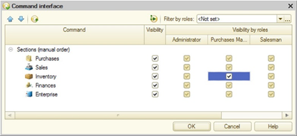
Fig. 622. Configuration command interface editor
In the Command column you can set the order of the sections.
The Visibility and Visibility by roles columns set the default visibility of the commands for opening subsystems.
35.3.1. General rules for setting visibility
The table field contains the general visibility control column (the Visibility column) and as many columns as there are roles defined in the configuration.
Initially, the order in which the commands are displayed and their visibility settings are set by the system. The user can still set up visibility for all commands as well as for specific commands selected by roles to which these commands are available.
You can set the object visibility in the command interface using several methods:
-
Edit the Visibility column. In this case command visibility is set for all roles. The command visibility for a particular role is defined by the Visibility column if a special visibility checkbox status is selected for the role. See the Sales subsystem visibility in fig. 622.
-
Select a visibility value (set or cleared) for a particular role. It will indicate that the command is visible or hidden by default (depending on the checkbox status) for the role. Common status (the Visibility column) is ignored in this case. In fig. 622, the Goods inventory section visibility for the Administrator role is disabled (although the common visibility box is checked) and the command to go to the Enterprise subsystem for the Sales manager role is visible by default (although the default visibility for this section is disabled).
Visibility status can be changed for multiple commands in the list.
To show only visible commands in the Command list press the Hide invisible by default button.
35.3.2. Filter by roles
In the Filter by roles field you can specify several roles that will define the current display of the command list. Only commands available to these roles will be included in the list. To disable filtering, select Not set. Use the selection list to enable one of the latest filters quickly.
35.4. Setting up the home page work area
35.4.1. Using the home page work area editor
Use this editor to set up a general layout of forms on the start page, as well as the list of forms that can be displayed on the start page.
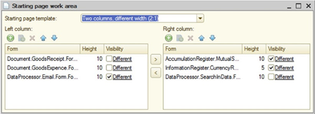
Fig. 623. "Home page work area" editor
The user can select a general layout of forms on the Start page in the Start page template field:
-
One column. Forms will be displayed in a single column.
-
Two columns of equal width. Forms will be displayed in two columns of equal width.
-
Two columns of different widths (2:1). Forms will be displayed in two columns, and the left column is twice as wide as the right one.
After the required forms have been selected, the user can specify their sequence order on the start page and height for each form (Height column).
The visibility editor is similar to other role-based property editors (see Role-based form customization).
When developing the interface of the start page, special attention should be paid to ensure that this interface contains the most important forms. These are forms that are most frequently used by users with a particular set of roles.
Please remember that forms that cannot be viewed by the user due to insufficient rights are not displayed on the start page regardless of the Visibility column status.
35.4.2. Software
You can also configure the composition and layout of forms on the start page (desktop) from 1C:Enterprise script. To perform configuration, you should use the methods GetForms() and SetForms() of the object HomePageSettings. Thus, it is possible to get the current status of start page (desktop) of the client application, modify the content as needed and set up it again.
Settings for the composition and layout of forms on the start page (desktop) are stored in the standard system settings storage. Settings key: General/HomePageSettings. To change the settings, first read them from the storage:
HomePageSettings
= SystemSettingsStorage. Download("General/HomePageSettings);Then the settings of homepage (desktop) can be modified and added back to the storage:
SystemSettingsStorage.Save("General/HomePageSettings", "", HomePageSettings);After saving the new forms composition, you need to rebuild the interface of the client application by calling the RefreshInterface() method.
Among the various uses of the mechanism, there are several basic scenarios:
-
Prompt the user to add a new form to the start page (desktop). This can be done using the program code that is called from the event handler OnStart. After changing the settings of the start page (desktop), you need to update the interface to make the changes available.
-
For some users, it is necessary to maintain a fixed set of forms, which is determined not at the configuration stage, but by some data from the information base. In this case, it is recommended to customize the start page (desktop) in the event handlerSessionParametersSetting of session module. In this case, you do not need to call the RefreshInterface() method, since the settings of start page (desktop) are being read after the execution of this handler.
-
Change forms on the start page (desktop) for all infobase users one time. In this case, it is recommended to write a program module that will go over the start page (desktop) settings for all users and make the necessary changes. Please remember, that the changes of interface made in such way are available to the user on the next login only.
Let us consider an example when you need to forcibly add the following forms to the home page every time you start the application: a list form of the Goods directory and a standard full-text search form (SearchForm). To show an example, find a common module with Server and Server Call checkboxes selected. Let the name of the common module is SetupInterface. The common module must include the following procedure:
Procedure StandardStartPage() Export
HomePage = New HomePageSettings;
Forms = New HomePageForms;
Forms.LeftColumn.Add("Catalog.Goods.ListForm");
Forms.RightColumn.Add("SearchForm");
HomePage.SetForms(Forms);
SystemSettingsStorage.Save(General/HomePageSettings", "", HomePage);EndProcedure
The managed application module must include the OnStart event handler:
Procedure OnStart()
WorkWithInterface.SimpleHomePage();
RefreshInterface();
EndProcedureAs a result, regardless of the settings of start page (desktop) configured by the user in the previous session, each new session will start with fixed configuration of the start page (desktop).
When configuring the settings of start page (desktop), you can specify both the full names of the forms of configuration objects (for example, Directory.Products.Form.FormName) and the standard form names (for example, Directory.Products.ListForm). Please remember that the start page (desktop) program settings to not modify the template of the home area (desktop). Upon the program setup, use the start page (desktop) template that is selected when setting up the start page (desktop) using the respective editor (see Using the home page work area editor).
35.5. Main section command interface editor
The editor is used to set up commands in each command bar, their display order and visibility of command interface items based on roles.
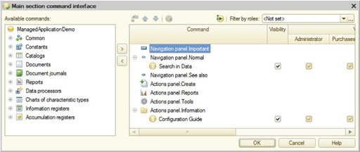
Fig. 624. "Main section command interface" editor
There are two table fields in the editor. The right one is used to edit the command interface, while the left one contains a hierarchical list of available configuration commands that can be added to the main section interface. Commands on the Available commands list meet the following criteria:
-
They have no parameters.
-
The group that is specified for the command belongs to the navigation panel or actions panel.
The Command column of the interface editor table field displays a structure of commands grouped by actions panel groups (Important, Normal, See also), navigation panel groups (Create, Reports,Service), and command groups defined in the Common – Command groups metadata tree branch. The table field contains the Command overall visibility column. The system also adds commands visibility columns for each role defined in the configuration.
To select a command, expand the appropriate branch in the available commands table and select the command. To move the command to the command interface, select it and click Add command to main section (alternatively, press Enter or double-click the command line). The selected command is moved to the panel and group defined for the command during setup of the current metadata object (Group property), the command of which is being moved. If the Add command to the main section button is not available, the selected command cannot be moved to the main section. For example, the Use standard commands property is not set for the enumeration.
Initially, command display order in the desktop command interface and their visibility settings are set up by the system. The user can set up visibility for all commands as well as for specific commands selected by roles to which these commands are available.
Use the Move command button to move commands between groups. Commands can also be dragged to the required position within groups of a single panel. To set up command order in a group, use up and down buttons.
Pressing the Set default properties button replaces the command visibility settings and group membership to the system default settings.
If the configuration has no subsystem, the editor looks different:
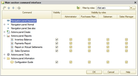
Fig. 625. No subsystems
In this case, all system commands are available on the desktop, and the user only has to set their default availability.
For general rules of visibility management, see General rules for setting visibility. For the description of filter by roles, see Filter by roles.
35.6. Command interface editor
The command interface editor enables you to set up commands in each command bar, their display order and visibility of command interface items based on roles.
The table field in the first (left) column displays the full list of commands grouped by groups (such as the Important, Normal, See also, Reports, Service, and other system groups, and groups defined in the Command groups metadata tree branch) of actions and navigation panels. The command list is followed by a column that manages the general command visibility.
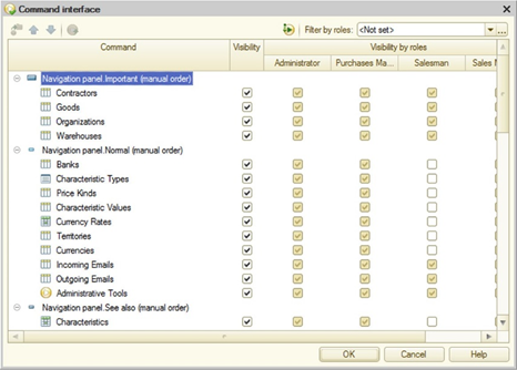
Fig. 626. Command interface editor
The system sets up the command order automatically. If you need to manually set up the command display order in groups, use the navigation buttons or drag commands. In this case, the line Manual command order is displayed next to the group. To undo the order changes, select Restore automatic command order in the context menu.
Use the Move command button to move commands between groups. Commands can also be dragged to the required position within groups of a single panel. To set up command order in a group, use up and down buttons.
Pressing the Set default properties button replaces the command visibility settings and group membership to the system default settings.
For general rules of visibility management, see General rules for setting visibility. For the description of filter by roles, see Filter by roles.
35.7. "All subsystems" editor
The All subsystem editor is designed to facilitate the solution of the following tasks:
-
Edit the command interface for any subsystem.
-
Set contents and properties for any subsystem.
-
Set up the subsystem order.
-
Edit subsystems.
Note. Note. The subsystem command interface editor can also be opened from the Command interface subsystem property using the Open link.
The Subsystems list defines the order of subsystems in the configuration tree. This order does not affect the order of the subsystems in the sections panel.
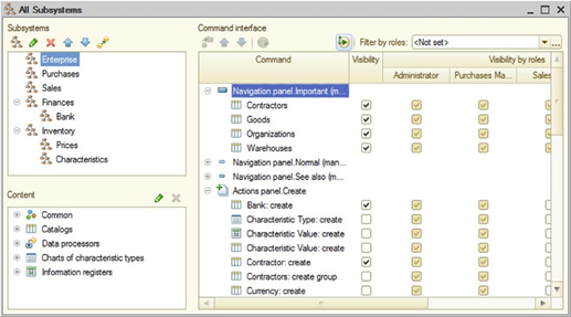
Fig. 627. "All subsystems" editor
To set up subsystem order in the sections panel, go to the desired element in the Subsystems list and perform the editing (subsystem order set up and relocation).
To edit subsystem properties, use the properties palette or subsystem editor (select subsystems and click the Edit current element button).
To move a subsystem (together with subordinate subsystems), select it and click the Move Subsystem button. In the object selection window that appears, specify the subsystem where the current subsystem will be moved. Transfer to subsystems included in the current subsystem is not allowed.
For general rules of visibility management, see General rules for setting visibility. For the description of filter by roles, see Filter by roles.
35.7.1. Subsystem content setup
The subsystem list is followed by the hierarchical Content list that is used to define metadata for the current subsystem. Note that the displayed content does not include metadata of subordinate subsystems if no metadata is defined in these subsystems.
To modify the content, click Edit subsystem components. It opens the object selection window with the metadata tree. The checked objects are included in the subsystem.
In the selection window, specify the objects that are to be included in the subsystem contents. Pressing the OK button closes the selection window and generates the subsystem contents.
35.7.2. Subsystem command interface setup
Subsystem command interface is configured in the table field located to the right of the subsystems and subsystem commands lists.
For general rules of visibility management, see General rules for setting visibility. For the description of filter by roles, see Filter by roles.
35.8. Query wizard
The query wizard enables you to create a query text in the module and edit an existing query.
To call the query wizard, open a module, select a procedure to add the query to, click the part of the procedure where the query code is or must be located, and select Text – Query – Wizard.
If there is no query, the following question is displayed: Query text not found. Create new? Click Yes to open the Query Builder window. If the query is being edited, the Query Wizard window with the current query data is opened.
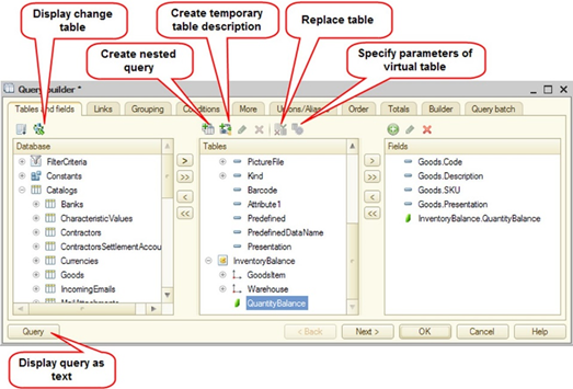
Fig. 628. Query wizard in the output form wizard
In fig. 628, the following buttons are numbered:
-
The Query button allows you to obtain the query in text format, in a separate window.
-
The Sort list button allows you to sort the list of objects alphabetically. To undo the sorting, click the button again.
-
The Show change tables button allows you to show the tables of changes for configuration objects in the list of objects as separate <ObjectName>.Changes branches. To hide the branches, click the button again.
-
The Show tables and fields of extended configuration button is available when the query wizard is opened from the configuration extension. When the button is click ed, the Database list contains objects of the extended configuration and objects of the current extension. If you click the button again, only extension objects will be listed.
The query editor opened from the extension allows you to open and edit a query that uses objects from the extending configuration, that are not added to the extension.
-
The Create nested query button opens a new query wizard where you should create a nested query. In the new query wizard, create the required query and click OK. This adds the nested query to the Tables list.
-
The Temporary table button allows you to create a temporary table. More information about this feature is provided below.
-
The Replace table button opens a dialog box where you can replace one query table with another. This will attempt to save all selected fields and correct table names.
-
The Virtual table parameters button allows you to open a dialog box for editing virtual table parameters if the cursor is on a virtual table in the Tables list.
To use the created temporary table, click Create temporary table description (see fig. 628). In the displayed form, add the table name and names of the required fields and, if necessary, specify the field value type.
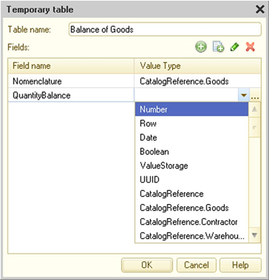
Fig. 629. Temporary table description
Using the Next> buttons in the query wizard, work your way through the tabs and select the necessary source data, specify groups and conditions, set the desired order and describe the resulting data. The wizard will generate a form and template in the appropriate branches. You can open a window with text generated on the basis of the specified query data at any time using the Query button.
To correct the data, use the <Back button.
On the Tables and Fields tab, select the required objects and drag them to the Tables and Fields sections.
To specify additional criteria, you can use the custom expression generation mode in the query. To do so, select Add from the Fields list in the context menu. The Custom expression window appears on the screen.
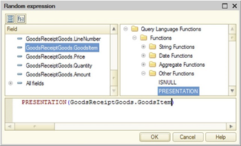
Fig. 630. Custom expression wizard
The expression text is generated in the bottom field. Alternatively, you can type the expression using the keyboard. You can drag the desired fields from the fields list and select the desired query language functions from the list by dragging them to the expression text box.
If several tables are specified, the Links tab is added to the query wizard form.
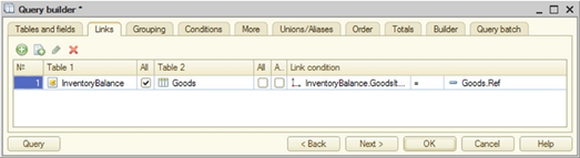
Fig. 631. Defining link conditions for tables
The Links tab enables you to specify the criteria for the links between the table fields. Click Add to add a new criterion and select one of the tables from the Table1 column; from the Table2 column select the table, the fields of which are linked with the first table fields. Controls that are used to create table link criteria are located below the criteria list.
On the Grouping tab, if required, select the attributes for grouping (see Grouping query results).
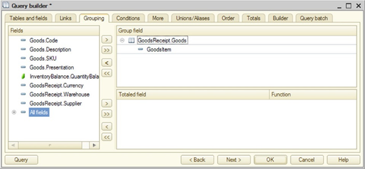
Fig. 632. Query result grouping
Specify conditions for source data filtering on the Conditions tab, if required (see Filtering query results).
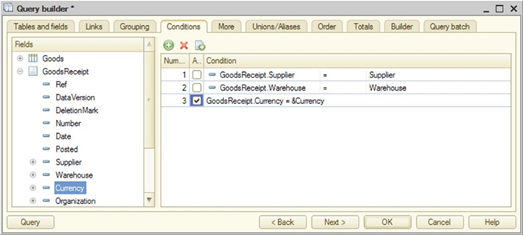
Fig. 633. Query conditions
For each selected field, choose condition type (for a custom condition, check the box in the Arbitrary column). If the box is not checked, select condition type and specify parameter description. If Arbitrary checkbox is selected, you can use the custom expression generation window (see above.)
Click the More tab to specify additional criteria for generating the data set.
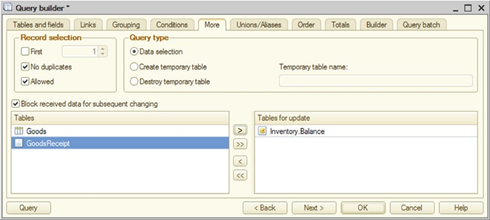
Fig. 634. Additional query parameters
On the tab, you can specify the number of records to select, whether to select only available records, and exclude duplicate rows. You can also specify what to do with the resulting data set: use it as a dataset, create a temporary table from the data set (see Creating temporary tables), supplement an existing temporary table with the created data set (see Adding data to temporary tables), or delete the temporary table. When operating with a temporary table, specify the name of the temporary table in the corresponding field. If you delete a temporary table, the wizard will significantly "simplify" its structure: only the current tab and the Query batch tab will remain.
If you selected to create a temporary table on the More tab, then on the appeared Index tab, you can specify which indexes will be created for this temporary table (see Indexing temporary tables).
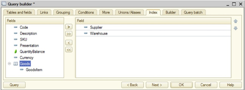
Fig. 635. Temporary table index
The rightmost column contains a list of fields included in the current index, which is selected in the leftmost column. Index names are predefined and cannot be changed. However, in the list of indexes, you can specify a flag indicating that this index will contain only unique records (the Uniqueness column). The middle column contains the fields of the indexed table that are not yet included in the current index. If only one index has been created for the temporary table, the INDEX BY clause will be used for it. If there are multiple indexes, the INDEX BY SETS clause will be used.
On the Unions/Aliases tab, add filed aliases, if required.
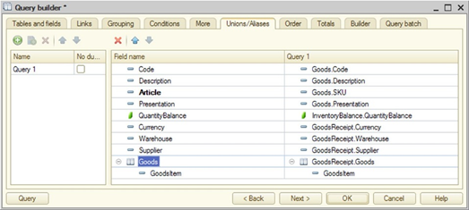
Fig. 636. Query unions/aliases
The table shows the mapping between the selected fields and source data. Field names and mappings can be changed. To change the name, select the field and press Enter, then add a new field name. To change the mapping, select the desired row in the Query column and press Enter. Select the desired value in the drop-down list.
If you want to select only unique values, check the box in the No duplicates column.
Aliases for fields that have been changed by the user, loaded from the query text or assigned mandatory aliases by the wizard at the alias generation step are displayed in bold.
On the Order tab, if required, specify the result output order (see Ordering of query results).
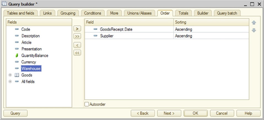
Fig. 637. Customizing the query result ordering
As shown in fig. 637, the output order for the data sorted by date is set, and the data is sorted by Vendor within a single date.
On the Totals tab, if required, specify which fields should be subtotaled and whether overalls should be generated (see Calculating query totals).
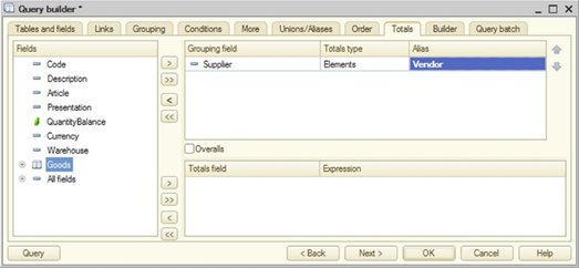
Fig. 638. Setting totals for a query result
If you press the >> button located next to the group fields, all reference fields are added to the group fields. If you press the >> button located next to the totaled fields, all numerical type fields are added to the list of totaled fields.
The report builder settings are provided in the Builder tab. Select tables and fields, specify conditions, order of presentation, and describe the total data.
-
Use the Tables tab to edit settings of virtual table report builder and mark optional tables. To edit virtual table settings, select the table and call the Virtual table settings command. After the dialog box opens, add the table settings required for the report builder. To mark an optional table, clear the Required checkbox against the table name. For optional tables you can also specify a group number. Optional tables with matching group numbers and adjacent link listing are combined into one optional group. Optional tables with different group numbers are distributed into different groups.
-
Use the Fields tab to select fields that the report builder uses as available fields in the report output.
-
Use the Conditions tab to select fields that the report builder uses as available fields for filtering.
-
Use the Order tab to select fields that the report builder uses as available fields to sort the results.
-
Use the Totals tab to select fields that the report builder uses as available fields for report grouping.
Use the Query batch tab to create a sequence of batch queries when using batch queries. You can edit and configure each query in the same window, and all the previous tabs can be used to switch between the queries being configured.
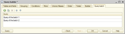
Fig. 639. Query batch
Clicking OK in the program module generates query text. If the wizard attempts to open invalid query text, the cursor is automatically placed in the query line containing the error and a troubleshooting message is displayed.
Depending on the source of the query wizard call (the data composition system, a query with a processing result, and so on), the wizard form can have new tabs that are described in the description of the tool where the query wizard is called from.
35.9. Query wizard with result processing
The wizard generates program code for processing query results. This wizard helps you create the following query result processing options:
-
Simple query result iteration
-
Output query results to a spreadsheet document
-
Output query results to a chart
To call the wizard, right-click the module editor and then click Query wizard with result processing.
When called, the wizard searches in the current line for the code that could have been created by the wizard. If such code is found, the wizard imports the found code (including template names and so on).
The query wizard window differs from the query editor described above.
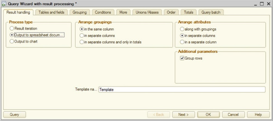
Fig. 640. Query wizard with result processing
In the wizard opened in this mode:
-
On the Processing result tab, you can select the query result processing type:
-
Iterate the result
-
Output to a spreadsheet document
-
Output to a chart
-
-
For the Iterate the result and Output to a chart query result processing types, the wizard form does not allow configuring any output parameters.
After clicking OK, program code is generated that will be inserted into the current module position. If the wizard has been called for the existing code, the old code is replaced.
If the results output to a spreadsheet document, a template is created in the metadata object, the object or form module of which has called the document. It is also modified when the wizard is called again. This template is removed if the wizard was previously used to create a spreadsheet document and is now called to generate another method of query results processing. If the wizard is called in a common module, a common template is created.
Note. Note. If the configuration editing mode is set for modes of managed application startup, the command to call the output forms generator is unavailable in the menu of metadata objects.
35.10. Register record wizard
Use the register records wizard for documents.
To launch the register record wizard, go to the Records tab in the document editing window, specify the list of registers that will be affected by the document and press the Register records wizard button. If a list of records for at least one register is defined for the selected document, this item is available in the context menu.
When launched the wizard asks the user to select a register for which the Posting() procedure is generated and opens the wizard window.
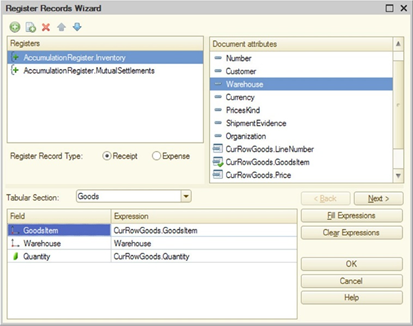
Fig. 641. Register record wizard
Initially, the list contains only the specified register. You can modify the list by adding registers from the list of registers marked on the Records tab of the document editing window.
For each register, specify preliminary settings depending on the register type: for balance accumulation registers, specify a register record type; for accounting registers that do not support correspondence, specify a correspondence type and an account; for accounting registers supporting correspondence, specify debit and credit accounts.
If the document has tables and their data must affect the register status, a table is included in the Table selection list.
Then, the attribute formulas are made for each register, according to the details of the document.
You should add to the list the formulas defining how to calculate the register records for the selected document attributes.
These formulas can be created "manually" as follows. The formula is added to the Formula column for each register attribute selected in the list. Formula can be manually entered or edited in this box. The wizard does not verify the formulas accuracy.
You can also add the corresponding attribute data in the formula by double-clicking in the list of the document attributes. The wizard does not check the matching of selected attribute types.
If at least one type belongs both to the attribute register and to the register dimension/ resource and their names match, Autofill mode can be used for these subordinate objects. When you click Fill expressions, the editable attribute name is added to the Expression column.
The wizard creates a Posting() procedure in the object module. At the beginning of the procedure, the wizard displays the following warning: This fragment was built by the wizard. All manually made changes will be lost next time you use the wizard.
35.11. Print wizard
The print wizard is designed to create a template with specified named areas and print procedures for a configuration object.
The print wizard works with the following configuration objects:
-
Catalogs
-
Documents
-
Document journals
-
Charts of characteristic types
-
Charts of accounts
-
Charts of calculations
-
Exchange plans
Basic techniques for working with the print wizard are discussed below on the example of working with the catalog. For other configuration object types, there may be some differences in working with the wizard.
To start up the print wizard point to the desired object in the Configuration window. Select Wizards – Print Wizard in the context menu.
Because the result of the print wizard operation is a print procedure located in an object manager module, the wizard begins by checking the accessibility of that module. If the object module has restricted access, a password dialog box appears. After you enter the password, the wizard window appears.
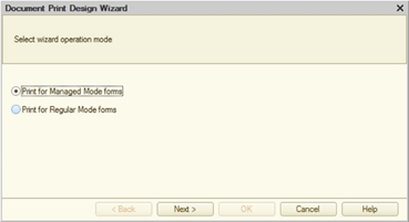
Fig. 642. Selecting an operation mode
First, the wizard prompts to select the startup option for which the print module is to be generated.
Then it asks the user to create a new print command or modify an existing command. Name must be specified for a new command. The default command name is Print. The specified name is subsequently used as:
-
Object command name
-
Command module server method name
-
Method name in an object manager that implements the print procedure
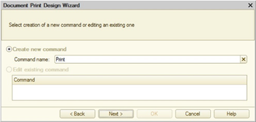
Fig. 643. Creating the print command
If the user chooses to edit an existing command, the following texts are replaced in the command module: CommandProcessing() handler, server method with the command name (Print() in this case), object manager module method with the command name and template.
After you press the Next > button, the wizard switches to selection of header attributes. Create the attribute list using the transfer buttons.
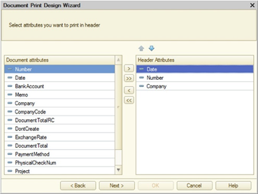
Fig. 644. Selecting header attributes
If the configuration object has tabular sections, then after the Next > button is pressed the wizard switches to selecting attributes of the next tabular section. The print list is generated the same way as the header attribute list.
If the configuration object has tabular sections, then after the Next > button is pressed the wizard switches to selecting attributes of the footer.
Then the user should select the group for the created command and specify certain parameters of the generated document.
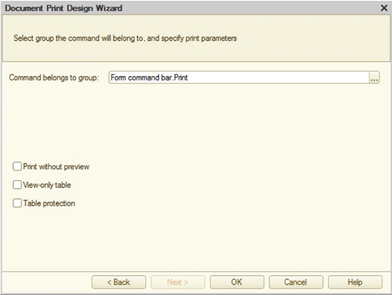
Fig. 645. Print wizard settings
Clicking OK closes the print wizard.
The wizard does the following:
-
Creates the Template template with a print form for the selected object (a form name matches the created command name).
-
Creates a command for the selected object. The command prepares a spreadsheet document and calls the server procedure (with the command name) that fills the transferred spreadsheet document.
-
Generates a procedure in the manager module of the selected object. Procedure parameters allow you to print several objects (a list) at once. The created command is assigned rights similar to the View right for the object that initiates wizard call.
35.12. Generation settings wizard
The Generation settings wizard makes it easier to develop a procedure to be used to generate a new object.
This wizard can be used for the following objects:
-
Catalogs
-
Documents
-
Charts of characteristic types
-
Charts of accounts
-
Charts of calculation types
-
Exchange plans
-
Business processes
-
Tasks
To launch the wizard point to the desired object in the Configuration window. Select Wizards – Generation settings wizard in the context menu. If Generate mode is defined for the selected configuration object, this item is available in the context menu.
When you start it, the Generation settings wizard window is opened.
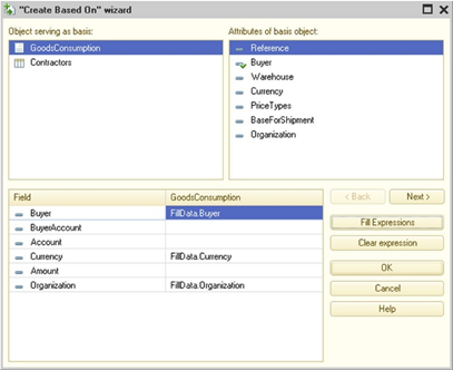
Fig. 646. Generation settings wizard
In the upper part you can see a list of base objects and a list of attributes for the base object selected in the first list.
The lower part displays a list of attributes for the resulting object. The object attribute list must be supplemented with expressions to specify how the document attributes are filled from the selected attributes for the base object.
These formulas can be created "manually" as follows. An expression is defined in the attribute entry Formula text box for the attribute of the object selected in the list. Formula can be manually entered or edited in this box. The wizard does not verify the formulas accuracy.
By double clicking in the list of attributes of the base object you can also insert correctly represented data of the corresponding attribute in the attribute Formula text box. The wizard does not check the matching of selected attribute types.
You can also combine these two methods: when being added to the input field, data from the list of base object attributes does not replace the entire information in the field but only the selected characters.
Clicking Auto fill expressions after request and confirmation creates filling formulas for base object attributes. Auto-filling does not change the previously filled formulas. Document attributes are matched with base object attributes according to the attribute names, IDs and types.
Clicking Clear formulas after request and confirmation clears all formulas created both automatically and manually.
When formulas are created for a base object selected from the base object list, they are retained in memory when a different base object is selected. So without ending the wizard session, you can create "Create-on-basis" procedures for several base documents. You can also resume editing the procedure for any base object by selecting it in the list again.
To end your wizard session use the OK or Cancel buttons (with and without saving your changes, respectively).
The wizard creates the Filling() procedure in the object module. At the beginning of the procedure, the wizard displays the following warning: This fragment was built by the wizard. All manually made changes will be lost next time you use the wizard.
The next time the wizard is used, all formulas previously generated for any base document appear in the document attribute list when the corresponding base document is selected in the base document list. The wizard opens formulas generated in its previous session to view and edit both automatically using the Fill formulas button and manually. Moreover, it also considers formulas entered manually into the document module if they are added to the procedure it generates. The wizard does not verify the formulas accuracy. For example, if filling with two different base document attributes is specified for a document attribute, the wizard selects one for display (by alphabet). This is the one that remains in the module after the wizard results are updated. The second line corresponding to the same attribute is deleted.
35.13. Configuration object form wizard
The Form wizard is launched whenever a new form is added to any configuration object that can include a subordinate Form type object. This special wizard is used to select the form type and set the configuration object attributes. The wizards have a great deal in common, despite substantial differences between the types of objects for which forms are created. Therefore, the use of form wizards will be shown using the document form wizard as an example.
When creating a new form object, the screen displays the form wizard.
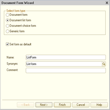
Fig. 647. Form wizard
The selections available under Select form type depend on the type of object for which the form is being created. The following forms can be created for the Document configuration object:
-
Document form
-
Document list form
-
Document choice form
-
Generic form (empty form)
The number of forms for each type is unlimited. If the object has multiple forms of the same type, you can choose one of them as the default form. When you open an object without specifying explicitly which form to call, the default form opens. To set a form as the default, select the Set form as default checkbox. You can later change the default form selection on the Forms tab in the object edit dialog box.
Selecting the Generic form type does not result in creation of a main attribute. In this case, the form behaves in a standard way. Selecting another form type results in creation of a main attribute and sets a different form type behavior. These exceptions are defined in objects known as form extensions (see descriptions of relevant object in the 1C:Enterprise script help).
Form type selection determines the main attribute type and consequently the entire form behavior, including the available toolbar commands.
Specify the form name, synonym and comment.
The functions of the command bars are determined by the action source and type of the form main attribute.
When the Finish button is pressed, the wizard automatically places the controls in the form and opens it for editing.
If form attributes have to be changed, click the Next > button. The composition of attributes depends on the form main attribute.
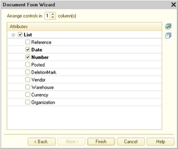
Fig. 648. Selecting form attributes
At this step, select attributes to place on the form. Selections are made in the Attributes column by checking the box to the left of the entry.
Note. IMPORTANT. The form wizard does not include non-displayable attribute types (such as ValueStorage) in the list.
35.13.1. Constant form wizard features
Each constant can have its own editing form. To create this form, click Create constant form in the context menu of the respective constant.
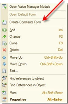
Fig. 649. Creating a constant edit form
Executing this command opens the common form wizard that lists all system constants as data, and the current constant is the only selected attribute (by default).
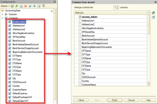
Fig. 650. Selecting editable constants
The same form is automatically generated by the system if the Main form constant property is blank and the Use standard commands constant property is set.
To create an editing form for multiple constants, create a common Constant form first and then select constants to edit on the attribute selection page.
Constant forms are included in the command interface of the subsystems that include the constant (if the Use standard commands property is set for the constant) and the common constant editing form (if the Use standard commands property is set for the common form).
If an editing form is created for the constant with the Use standard commands property set, the common form wizard clears the Use standard commands property for the form. So, constant editing forms are only included in the command interfaces of the subsystems that include the constant.
35.14. Template wizard
Use the template wizard to create configuration object templates and common templates.
The wizard window appears when you select Actions – Add if the branch of the subordinate Templates or Common templates object is selected.
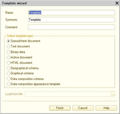
Fig. 651. Template wizard
Specify the name, a synonym and a comment and choose the template type
The Spreadsheet document type assumes you use the standard 1C:Enterprise method to create and use spreadsheet document templates.
Text document template type assumes the use of text documents specially prepared as templates. For a text document, the Extension property means the Text template.
Selecting the Binary data type means that the configuration developer knows how to work with this type of object.
The Active document type enables you to use the OLE Active document technology. If you press Finish, the wizard searches for available Active document types and offers to select one of those it finds.
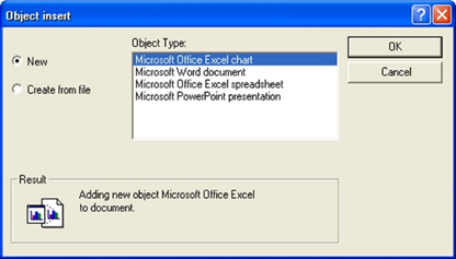
Fig. 652. Active document insertion
You can select a ready Active document and use it as a basis for template creation (load template prototype from a file). If you selected a file, the type of which is not on the list of supported Active documents, the wizard displays a warning.
Selected document is saved to the configuration. Working with the template, you must use properties and methods provided by the selected platform.
If you select the HTML document type, the HTML template editor opens. This mode supports all the HTML editor features. In addition, the HTML template editor allows you to use pictures from the picture library, from a file, from a collection file, or from "internal" pictures. Internal images are pictures that are already selected from a file and stored "inside" the template.
To add a picture to a template, select Elements – Picture...
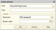
Fig. 653. Inserting a picture
To select a picture, click the selection button. Select the required picture in the window that opens.
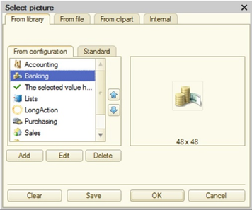
Fig. 654. Selecting a picture
Select the Geographical schema type to create templates using documents prepared with the geographical schema editor.
If the Graphical schema type is selected, you can use graphical schemas prepared in the graphical schema editor or download schemas from files and use them as templates.
The Data composition schema type opens the data composition schema wizard.
Select the Data composition appearance template type to open the appearance template wizard window (see Appearance template).
Select the Add-ins type allows you to import add-in into ZIP archive. The archive should include the files of external components and a special manifest. You can use an add-in imported this way both in an ordinary application and in a mobile application.
35.15. Format string wizard
Use the format string wizard to write expressions using numeric, date, and logical expression presentations.
To open the wizard, hover the cursor over the required module text area and click Text – Format string wizard. For a new string, the editor displays the following message: Format string not found. Create new format string? Clicking Yes displays the wizard window.
You can also call the wizard from the Format and Edit format properties of a form item. In this case, click the selection button in the appropriate property.
Window tabs correspond to the data type of the format string to be generated in the window.
Controls for selecting a presentation format are located on three tabs according to data types:
-
Number
-
Date
-
Logical values
Language (Country) field (L parameter) defines information presentation based on the regional settings. Values specified in the following tabs take precedence over country settings.
Select the Number tab for numbers.
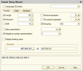
Fig. 655. Format string wizard for numbers
Length field (ND parameter) specifies the total number of decimal places (for the integer and fractional parts). Precision field (NFD parameter) states the number of decimal places in the fractional part.
Shift field (NS parameter) specifies the digit shift. If the field value is positive, the number is divided by 10 to the appropriate degree. If the field value is negative, the field value is multiplied.
Decimal separator field (NDS parameter) specifies the decimal separator.
Digit Group Separator field (NGS parameter) specifies the group separator. When separator is set to an empty string, non-breaking space is used as a separator.
Grouping field (NG parameter) specifies the option for grouping digits in the integer part of a number.
Zero presentation field (NZ parameter) is used to select how zero values are represented. This parameter can be used in a format string, but it is not used for text boxes.
Negative number representation field (NN parameter) specifies how negative numbers are represented.
Leading zeros are displayed when Display leading zeros (NLZ parameter) is selected.
Note. Tip. The bottom part of the wizard window displays format string results (Example group) and the format string itself.
Select the Date tab to set the date.
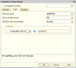
Fig. 656. Format string wizard for dates
The date presentation option is selected in the Date format field (DF parameter). It is recommended to use this format in the case when you need to get exactly one or the other date format, regardless of the localization parameters. For example, for the format string DF = yyyy-MM-dd, the date presentation always looks like 2015-12-01.
The local date presentation option is selected in the Local Date Format field (DLF parameter). No selection of DD parameter value is allowed for text boxes. It is recommended to use this date presentation option when you need to take into account the current localization parameters. Localization parameters can be specified both directly in the format string and can be generated from the regional settings of the infobase.
Example:
Format('20151201', "L=ru;DLF=D") = 01.12.2015
Format('20151201', "L=en_US;DLF=D") = 12/1/2015
Format('20151201', "L=ru;DLF=DV") = 01.12.2015 0:00:00
Format('20151201', "L=en_US;DLF=DV") = 12/1/2015 12:00:00 AMThe blank date representation option is selected in the Blank Date Representation field (DE parameter). This parameter can be used in a format string, but it is not used for text boxes.
Note. Tip. The bottom part of the wizard window displays format string results (Example group) and the format string itself.
For Boolean type data, select the Boolean tab.
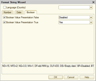
Fig. 657. Format string wizard for logical values
If a value is not selected, default settings are used.
For details on format string parameters see description of the FormatString parameter for the Format() method in the 1C:Enterprise script description.
If the format string wizard is used, the generated format string is inserted into the text (or text box) when clicking OK .
Note. Tip. In the text editor, you can hover the cursor over the format string and edit it by selectingText – Format string wizard in the menu.
35.16. Wizard for strings in different languages
Use this wizard to edit strings in all configuration languages and other languages, if their codes are included in the edited set, but not in the configuration.
The wizard produces the following string:
<language_code1> = <String_1>; <language_code2> = <String_2>;…It is convenient to use the wizard to create the InitialString parameter for the global context function NStr().
To open the wizard, hover the cursor over the required module area and select Text – Multilingual string wizard. The editor analyzes the module text where the cursor is located and, if the construct is found, opens the wizard window. If the construct is not found, the wizard informs the user about it.
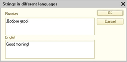
Fig. 658 Wizard for strings in different languages
The wizard window contains as many text boxes as there are languages in the configuration.
Add a text and click OK. The wizard produces the following string:
ru = 'Доброе утро!'; en = 'Good
Morning!'35.17. Spreadsheet document editor
The Spreadsheet editor in 1C:Enterprise allows you to create various print forms and forms for viewing and adding information in spreadsheet documents.
For a table of shortcuts for the spreadsheet editor, see the help in the application.
35.17.1. What is a spreadsheet document in 1C:Enterprise
Although you can use 1C:Enterprise spreadsheets to add, process, and display information like in standard spreadsheets (using spreadsheet documents in a form), they are mainly used to view processed information, for example, a description of a report print form. Program modules in the 1C:Enterprise language are used to process information and store it on the spreadsheet for most configuration objects.
The 1C:Enterprise spreadsheet editor is used to work with spreadsheet documents and print form templates.
Generated spreadsheet documents can be saved to disk in various formats. If a document is saved in MXL format, you can view it later in the file manager that is available at: http://v8.1c.ru/metod/fileworkshop.htm. It is not recommended to include OLE objects in a saved spreadsheet document if it is to be used in a web client or other that Windows operating systems.
Templates are stored in the configuration. There are common templates, which are located in the Common – Templates branch. For example, templates of standard payment documents printed based on different documents. Also, there are templates for specific configuration objects, for example, a fixed asset card. A configuration object may have several print form templates.
Spreadsheet documents may also be placed in a form. For this purpose, use the Spreadsheet document field control. In this mode other controls can be inserted into a spreadsheet document.
Templates and spreadsheet documents in terms of work practices are almost the same.
Spreadsheet documents (files and templates) may be compared and merged.
35.17.2. Templates
You can use an add-in imported this way both in an ordinary application and in a mobile application (see Template wizard).
35.17.2.1. Designing templates
Designing a template involves creating its components and building blocks (named areas) that constitute an output form, that is a report. Since nearly all business documents have a rectangular structure, it is best to create templates for these documents in an editor that supports rectangular elements.
This feature is provided in the 1C:Enterprise spreadsheet editor. While creating a template, you can do the following: enter a text into spreadsheet document cells, specify formatting parameters (for the entire cell), adjust row height and column width, add drawings (lines, rectangles, pictures, OLE objects, charts, and other graphical objects). You can also customize the appearance for the entire spreadsheet document or separate cells and cell groups.
When creating a report template, follow these guidelines.
Basically, every report has a header with the name of the report and source building parameters. To generate such data, a named area should be created, which is often called the Header. If a report contains a tabular section, the header usually contains column names.
Create named areas (in the example in fig. 659, it is Row) to output information to a table. It is normally impossible to know the number of spreadsheet rows in a template in advance; however, the structure of information is always the same. Therefore, the same areas should be used for each row description, when creating a report. Various parameters (in the example, these are Account, Name, Price, Amount, and so on) must be assigned to cells to output specific information. When displaying the next row, the contents of each output row are assigned to these parameters, and then the generated area is included in the report. This procedure is repeated until all information on the spreadsheet is output.
Normally, the report ends with the output of resulting data and details of the responsible persons. This data is usually located in the area called Footer.
The final template is a combination of rectangular areas. Each area displays a completed report part: a title area (displays a name, a date, and so on), a table header area, and other areas.
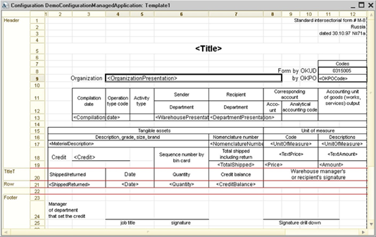
Fig. 659. Sample template
Reports are generated as follows:
-
Reports are initially created as blank spreadsheet documents. Note that a template is not directly linked with the finished report. A template is a wizard or a set of areas used by the module to generate reports.
-
When the report algorithm is processed, named areas are extracted from the template in the required order, translated (parameters are replaced with values), and copied to a spreadsheet document of the report. Report generation language tools allow you to expand reports both horizontally and vertically.
35.17.2.2. Template cell properties
Specifying template properties
Template properties are shown if the Template property is set in the spreadsheet document properties.
Fill. The Fill property items specify what kind of information is added to a cell. The property is shown if the Contains value property is not set in the Values properties. The items do not change the cell appearance, but are used only during template processing, when generating a finished spreadsheet document.
The items of this list have the following meaning:
| Data format | Note |
|---|---|
| Text | Information in a cell is a text, and when generating a spreadsheet document, it will be transferred from the template to the finished spreadsheet document without changes. The text is contained in Text property and can be either text or a formatted string. |
| Parameter | Cell information is a parameter whose name is specified in the Parameter property. The Text property will be ignored. |
| Template | Information in the cell is a text that includes parameter names enclosed in square brackets. When a spreadsheet document is generated, the variables will be calculated and included in the text. The space given in the text for displaying parameter values is determined by the length of these values. Template sample: CEO: [CEO]. The template line text is located in the Text property and can be either text or a formatted string. |
The information in the cell of the finished spreadsheet document is converted to the String or FormattedString type (if formatted strings were used to generate the resulting value).
Parameter. A parameter name to output cell contents. The property is shown if the Contains value property is set in the Values properties or when the FillType property of the Template properties is set to Parameter. If a formatted string is substituted as the parameter value, the base format for the substituted value in the resulting string is determined by filling type (the FillType property value). Generation of the parameter remains the same:
-
Parameter. The basic value formatting is determined by the cell formatting.
-
Template where the template is a regular string. The basic value formatting is determined by the cell formatting.
-
Template where the template is a formatted string. In this case, the basic value formatting is the formatting of the "[" character in the name of the parameter to be replaced.
Details parameter. Specifies a parameter name for cell value drilldown processing. Use this property when the resulting spreadsheet document is located on a form (the Spreadsheet document field control).
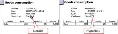
Fig. 660. Cursor types in a spreadsheet document
When you open a finished spreadsheet document in the Read only mode and hover the mouse over a cell with the Details parameter property filled, the mouse pointer might look as shown in fig. 660. A cursor of the Hyperlink type is only displayed if the Hyperlink property is set for a link cell. This means that you can drill down to the details of a spreadsheet document data. Now, if you double-click this cell (or make it active and press Enter, or simply click it if it is a hyperlink), the field value will be displayed:
-
String, Number, Date, and Enumeration values will be opened for viewing.
-
For Document values, a corresponding document will be opened for viewing and editing.
-
If a value is a catalog item, this item is opened for viewing and editing in a dialog box. If editing in the list feature is turned on in the catalog properties, a catalog list form will be opened and the spreadsheet field pointer will be moved to the required catalog item.
This drilldown processing is called standard and does not require any additional settings.
If you need a special drilldown processing, specify a name of the procedure that handles the event occurring when you select a cell with drilldown in the spreadsheet document properties in the Events category for the Details processing event. In the form module, in the body of this procedure, describe the drilldown processing.
Consider the example below. A form and PrintTemplate template have been created for a report. The template includes named areas Title, Header, GoodsHeader, and Goods. The Goods area contains a cell with the Details parameter. The form contains the Table form element associated with the Spreadsheet form attribute of the SpreadsheetDocument type. The Details processing property in the Events category refers to the cell selection processing procedure ResultDetailProcessing() located in the report module.
To generate a spreadsheet document, a following exemplary scheme is used:
Spreadsheet.ShowGrid = False;
Spreadsheet.ShowHeaders
= False;
Spreadsheet.Protection
= True;
Spreadsheet.ReadOnly = True;
Template = Documents.GoodsConsumption.GetTemplate("PrintTemplate");
// Title
Area = Template.GetArea("Title");
Spreadsheet.Output(Area);
// Header
Header = Template.GetArea("Header");
Header.Parameters.Fill(ThisObject);
Spreadsheet.Put(Header);
// Goods
Area = Template.GetArea("GoodsHeader");
Spreadsheet.Output(Area);
GoodsArea = Template.GetArea("Goods");
For Each CurRowGoods
From Goods Do
GoodsArea.Parameters.Fill(CurRowGoods);
Spreadsheet.Output(GoodsArea);
EndDo;Example of procedure that processes drilldown selections:
Procedure ResultDetailProcessing(Item, Details, StandardProcessing)
StandardProcessing = False;
DetailsType = TypeOf(Details);
If DetailsType = Type("CatalogRef.Products") Then
ReportFormName = "ReportForm1";
Else
ReportFormName = "ReportForm2";
EndIf;
ReportForm = DataProcessorObject.GetForm(ReportFormName);
ReportForm.RunReport(Details, PeriodFrom, PeriodTo);
ReportForm.Open();
EndProcedureReportForm1 and ReportForm2 are forms developed specifically for detailed reports. Usually these forms contain a spreadsheet document field where the result is output.
Details usage. Defines an area where the drilldown mechanism is used. If you select a cell, you can drill down only to the specified cell; if you select a row, you can drill down to any cell in the current row. If you select Do not use and specify a drilldown, it becomes invalid: the cursor does not change its appearance (see fig. 660) and the selection in a cell is not processed.
Specifying value properties
Contains value. If this option is set, a cell contains a value. Setting this property affects the properties of other categories.
Value type. Cell value type. For spreadsheet documents, this list contains the Number, String, Date, and Boolean types. For the Spreadsheet document field form control, the list also contains types defined for the current configuration, including documents, catalogs, enumerations, and other in addition to primitive types. The Arbitrary data type may be added as well. This data type may be determined using 1C:Enterprise script tools during the form filling.
Control. A control is selected for editing cell contents. The list of possible values depends on the selected content type. For example, if Number data type is selected, Text box or Checkbox may be used as an editor. A row with the editor type Text box or Checkbox is added to the object list (Cells, Spreadsheet Document) for the specified editor type. Contents of the properties palette for this object depends on the type of selected control.
Format. Sets a format string to be used when displaying a value. If the display format is not configured, it is selected from the infobase regional settings.
Editing format. Sets a format string to be used to display a value when editing. If the display format is not configured, it is selected from the infobase regional settings.
You can enter the format manually or using the format string editor (see Format string wizard).
Note. Note. When a spreadsheet document is edited in thin client, the following cell properties are unavailable: Contains value, Value type, Control, and Editing format.
35.17.3. Spreadsheet document in data input mode
Another way to build a report is to add data into the designated cells of a spreadsheet document placed into a form element.
During the input process, this data is processed by procedures written in 1C:Enterprise script located in the form module. Calculation results can be used to calculate values for other spreadsheet document cells.
After you enter data, you can print a report and save it for future use.
The overall procedure for working with a spreadsheet document in the data input mode looks as follows:
-
Generate a Spreadsheet document template that will be used for data input.
-
Generate a form containing the Spreadsheet document field for data input.
-
Generate the Spreadsheet document form item handlers to process user-entered data (if necessary).
Let us review the steps listed above using an example of how to generate a goods delivery form based on the GoodsDelivery document. The target form is shown in fig. 661. In this form, the underlined fields must be filled by the user. Delivery date field value is automatically calculated by summing up the Issue date and Delivery period values. Issue date is the document date.

Fig. 661. Delivery form
35.17.3.1. Preparing spreadsheet documents
To represent a table box in the data input mode, a Spreadsheet document template must be created (with the DeliveryForm name). The generated template is then to be opened, and its Template property is to be set to False.
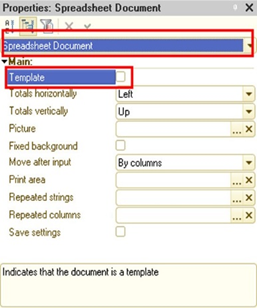
Fig. 662. Spreadsheet document properties
Then the required structure must be created for the document to be generated.
Create the required fields:
-
Delivery address. Merge several cells and define the following properties:
-
Name: DeliveryAddress;
-
Protection: False;
-
Contains value: True;
-
Value type: String;
-
Control: Input field.
-
-
Delivery time. Define the following properties for the cell:
-
Name: DeliveryTime;
-
Protection: False;
-
Contains value: True;
-
Value type: Number, length: 3, precision: 0, non-negative;
-
Control: Input field.
-
-
Delivery date. Define the following properties for the cell:
-
Name: DeliveryDate;
-
Protection: False;
-
Contains value: True;
-
Value type: Date, date content: Date;
-
Control: Input field.
-
-
Document date. Define the following properties for the cell:
-
Name: DocumentDate;
-
Protection: True;
-
Contains value: True;
-
Value type: Date, date content: Date;
-
Control: Input field;
-
Format: DLF=DD.
-
The result should be the following spreadsheet document:
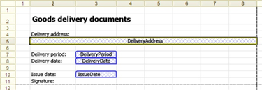
Fig. 663. Finished template
The Show named cells mode is enabled for the template (select Table – Names – Show named cells in the menu).
Note. Note. Properties that can be set for the text box in the template are neither saved nor used by the system to generate text boxes in spreadsheet documents in the data input mode.
35.17.3.2. Preparing forms for data input
After the spreadsheet document template has been finished, generate the form to be used for data input and implement a procedure to call it from the document.
Create ExecuteDelivery command with the following code in the document:
&AtClient
Procedure ExecuteDelivery(Command)
DeliveryParameters = New Structure("DocumentDate", Object.Date);
OpenFormModal("Document.GoodsDelivery.Form.DeliveryExecution", DeliveryParameters);
EndProcedureThe command should be placed in the form.
Now you need to create a form to be used for data input.
To do this, create the custom DeliveryExecution form in the GoodsDelivery document. Create the following form items:
-
DocumentDate form parameter of the Date type
-
DocumentDate form parameter of the Date type
-
SpreadsheetDocument form attribute of the SpreadsheetDocument type
-
SpreadsheetDocument form item related to the SpreadsheetDocument form attribute
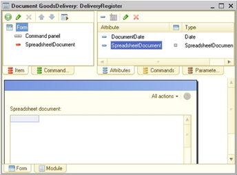
Fig. 664. "GoodsDelivery" form
Then implement the following handlers in the form:
&AtServer
Procedure OnCreateAtServer(Cancel, StandardProcessing)
// Save document formatting date
DocumentDate = Parameters.DocumentDate;
// Set finished template
SpreadsheetDocument = Documents.GoodsDelivery.GetTemplate("DeliveryForm");
// Set document creation date in a spreadsheet document field
SpreadsheetDocument.Area("IssueDate").Value = DocumentDate;
EndProcedure
&AtClient
Procedure OnOpen(Cancel)
// Activate spreadsheet document area
Items.SpreadsheetDocument.CurrentArea = SpreadsheetDocument.Area("DeliveryAddress");
EndProcedureAs a result, the following form filled with data is acquired:
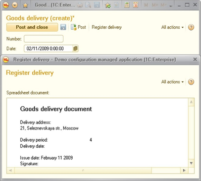
Fig. 665. Delivery form
35.17.3.3. Implementing a response to spreadsheet document cell changes
The acquired form has no automatic recalculation for Delivery period and Delivery date fields, if they are changed.
To make this recalculation possible, you shall implement the corresponding event processing for the form attribute associated with the spreadsheet document.
You need to add the OnChangeAreaContent handler for the SpreadsheetDocument form item. The handler should contain the following program code:
&AtClient
Procedure SpreadsheetDocumentOnChangeAreaContent(Item, Area)
SecondsInDay = 24 * 60 * 60;
If Area.Name = "DeliveryDate" Then
SpreadsheetDocument.Area("IssueDate").Value = (SpreadsheetDocument.Area("DeliveryDate").Value - BegOfDay(DocumentDate)) / SecondsInDay;
ElsIf Area.Name = "DeliveryTime" Then
SpreadsheetDocument.Area("DeliveryDate").Value = BegOfDay(DocumentDate) + SpreadsheetDocument.Area("DeliveryTime").Value * SecondsInDay;
EndIf
EndProcedureNow the spreadsheet document has obtained the desired interactivity.
35.18. Flowchart editor
Flowchart is a schematic presentation of the sequence of actions for a business process. It is a special case of the graphical schema.
The main difference between a flowchart and a graphical schema is a special processing of special schema items (start point, end point, actions, conditions, and so on).
Flowchart is also an instruction for the application on business process actions execution sequence, an illustration for the user of this actions structure and a tool used to display the current state of a business process (description of theGetFlowchart() method is available in the 1C:Enterprise language help).
Flowchart is represented by a rectangular screen area that contains different items, for example, start point, end point, decorations, connecting lines, and so on.
35.18.1. Editing flowcharts
To edit the flowchart, in the business process edit window on the Other tab press the Flowchart button.
Flowchart editing is done by placing various map items on the flowchart, editing their properties and joining them using the connecting lines.
Flowchart is edited with a mouse or a keyboard. You can perform some operations only with a mouse, for example, join flowchart items using connecting lines. When a flowchart is opened, the Inserting flowchart items toolbar buttons and the Flowchart upper level menu item become available on-screen.
Flowchart properties are configured using the property palette (see Property palette).
35.18.2. Flowchart items
35.18.2.1. Design recommendations
The best approach for drawing flowcharts is using the vertical orientation of the map. The flowchart assumes vertical arrangement (top to bottom). For example, when adding the Activity item flowchart (hereinafter referred to as " an item" in this section), it is created with an outgoing connecting line directed downwards.
When creating labels, it is desirable to use identical fonts. Using a different font is an additional way of attracting attention (for example, in a decoration header highlighting a group of items).
Use the flowchart editor to place various items into flowcharts, to specify their size and level borders, and so on.
To simplify item placing, flowchart editor provides various service tools. These include the use of a grid and performing various actions on an item group (leveling, flowchart distribution, size setting, and so on).
As an additional feature, you can use the individual item design. Using the Design category features, you can customize text and background colors, text font, use pictures, tooltips and other design techniques. Property content depends on the item type.
35.18.2.2. Graphical schema item order
Unlike the regular graphical schemas, certain types of items in the flowchart retain the order characteristic of the item type, even after the order changes. Precisely:
-
Decorations are always located in the background (below). It means that you can change the order of decorations only relative to each other, and they will always be lower relative to other items.
-
Following the decorations (above them) are the connecting lines.
-
On the very top, all other items are located (visualizing points of the business process). This way, items constituting the logic of the flowchart are always placed above the decorations and decorative connecting lines in drawing order.
35.18.2.3. Using connecting lines
A flowchart is used to describe business process sequences. It is defined by linking items using the Connecting line item. Connecting lines must always be connected to certain points in the business process and cannot exist by themselves. Connecting lines cannot be deleted, unless this feature is provided by the point in the business process (for example, splitting point and switch point).
You can link all items used for visualization of business process points, that is all items except Decoration, Connecting line, and Decorative line items. By default, most items used for visualization of business process points are inserted into the flowchart with one outgoing line that cannot be detached or deleted. It can only be moved to a different port. Port is an item area where a line can be connected. This is usually the middle of the side of a rectangle that contains the item. On the schema, a free port is indicated by a blue cross.
To operate with the Connecting line flowchart item, you need to select it by clicking on any segment (interval) on the connecting line or by using the Tab (Shift + Tab) key.
If the end of the line is not connected to an item, the rectangle at the end of the line is colored in red and the arrow has a contour and is not filled inside. To connect, use the mouse to grab the end of the connection line (gray or red rectangle) and drag it to the port area of any item, drop it there. After this, the connecting line is automatically rebuilt. You can also reconnect the connecting line (by connecting it to a different item). The following restriction is applied: you cannot directly loop one item on the other (point1 à point2 and point2 à point1) if none of them is an item of the Condition point or Switch point flowchart.
When inserting an item into the flowchart, an attempt to connect the free ports of this item to nearby non-connected lines is automatically made. When moving or resizing an item, there is an automatic attempt to connect the free ports of this item to the closest available (unconnected) lines and to the outgoing lines of this items, with the line end not connected to free ports of other items located in close proximity.
Decorative line item is used to connect decorations and flowchart points. Any number of decorative lines can be placed in the flowchart.
35.18.2.4. Flowchart correctness check
The flowchart is checked for correctness when selecting Flowchart – Check item and automatically when saving the flowchart. The following incorrect situations are checked:
-
Looping
-
Detected unconnected lines
-
Detected route points that are not a starting point and have no incoming lines at the same time
-
Flowchart that does not have a starting point
-
Detected route points without a path to the end point
-
Flowchart where some lines that did not enter the merge point left the corresponding split point
-
Flowchart where parallelized branches (coming out from the split point) enter the same route points (before merge point)
-
Flowchart with loops that do not contain a single Action point, Nested business process point or Processing point point type. A loop is a unique looped route point sequence
-
Flowchart where a route point of the Condition point or Switch point type has no event handler (ConditionCheck() or Switch() respectively)
35.18.3. Flowchart items
This section describes all types of flowchart items that are listed in an alphabetical order.
Items behavior is configured in the properties palette by setting and selecting values. Some item properties are shared by all or most items. Individual properties of each item are given in 1C:Enterprise script help.
35.18.3.1. Common flowchart item properties
There are many properties that are shared by all or most item types. Usually these properties have a common purpose and can be edited in a uniform manner. You will find a description of these properties below. For more information on editing the unique properties of items, see the sections dedicated to individual item types.
Only the properties that distinguish the flowchart items different from graphical schema items are described.
For easy description, the properties are grouped by category of the properties palette.
Some properties that are described later in this document might be unavailable for specific items.
35.18.3.1.1. Specifying general properties
Task description is a description of the task to generate in points of the Activities or Nested business process point type.
35.18.3.1.2. Specifying event properties
This category properties determine the business process points behavior for specific actions. For example, for interactive activation, task creation, condition check (for the Condition point items), and so on.
When working with items, most actions can initiate the launch of procedures related to these actions. 1C:Enterprise script describes the event handling in the body of each procedure.
Fig. 666. Creating an event handler
To start creating a procedure responsible for handling an event, click a special button on the property palette located to the right of the attribute with the event name in the Events property category (see fig. 666).
Procedures are created in a business process module that feature is editable map of the route.
When working with a business process, upon the occurrence of an event, the program execution control is passed on to the procedure associated with this event.
For a list of flowchart events or items along with conditions that invoke them, see the relevant object description in the 1C:Enterprise script help.
35.18.3.2. Connecting line
Connecting line flowchart item is used to connect flowchart items visualizing business process points, for example, the Start point, Activity, Condition point, and other items. Connecting line item is automatically rearranged when you change the item positions. You cannot modify the connecting line creation algorithm.
Connecting line is inserted automatically when you insert other flowchart items and cannot exist on its own. You can insert additional connecting lines only in the Splitting point and Switch flowchart items.
When drawing a line, an application attempts to create the shortest path consisting of vertical and horizontal line segments that do not cross other schema items.
35.18.3.3. Activities
The Activity flowchart item displays a business process point used to generate and execute tasks.
35.18.3.3.1. Specifying addressing properties
Explanation. It is a string that additionally describes the activity addressing. It is used when addressing attributes are inserted by 1C:Enterprise script and are not set in advance at the design stage of the flowchart.
Group. If this property is set to True, the tasks for this business process point are assigned to all group (department) members. Otherwise, one task is assigned to the entire group, for example, Sales Department, and only one person (the first who undertakes it) executes this task.
Addressing attributes. The number of these properties is equal to the number of addressing attributes for a task selected in the Task property of the business process. You can use the property palette to select one of the predefined values whose type is specified in the task addressing attribute, for example, from the Departments or Performers catalogs.
35.18.3.4. Splitting points
The Splitting point flowchart item represents a business process point where the work-flow is split into several parallel threads. By default, it is placed is a flowchart with three outgoing connecting lines.
To add an outgoing line to this item, right-click it and then click Add outgoing connecting line. To delete an outgoing line, right-click the line and click Delete. You cannot delete the only remaining outgoing line.
35.18.3.5. Condition points
The Condition point flowchart item is a business process point that has two possible exit points based on a logical condition.
By default, Condition point is inserted into a graphical schema with two outgoing connecting lines from the left side and from the right side. The right thread is a process branch when returning the True value of the ConditionCheck()handler. You can swap the condition branches. To do so, drag a rectangle at the beginning of the Condition point line to the opposite side of the Condition point item.
35.18.3.6. End points
The End point flowchart item represents the end point of a business process. A flowchart can have several items of this type.
35.18.3.7. Start points
The Start Point item represents the business process start point. If a business process has several points of the Start point type, specify the required start point when you run the process. The Start point item cannot contain connecting lines.
35.18.3.8. Joins
The Join flowchart item represents a business process point of joining of parallel execution paths that begin at splitting point. Until the task execution for all parallel paths reaches the join point, no transition to the point following the join is executed. One join point always corresponds to one splitting point (but not vice versa, since there can be splitting points without join points). You do not have to specify explicitly which Join item corresponds to the Splitting point item. It is determined automatically.
35.18.3.9. Sub-business process points
The Sub-business process point flowchart item represents a business process point where a business subprocess starts to execute. Execution of the main (parent) process resumes only after the subprocess is complete.
35.18.3.9.1. Specifying data properties
Business process is a reference to a business subprocess.
35.18.3.10. Data processor points
The Data processor point flowchart item represents a business process point that is executed in automated mode and has no destination.
35.18.3.11. Switches
Switch flowchart item represents a business process point with several exits (options), only one of which is selected based on the Option return parameter value of the SwitchProcessing() handler.
35.18.4. Modules
Flowcharts do not have their own modules. Event handlers are added to a business process object module.
35.19. Image editor
35.19.1. General information
Designer offers an editing tool for images and image collections.
Pictures are stored in the Common – Common images branch or in the files on the local hard drive.
To create a new image, use the Actions – Add command in the Common – Common images branch and then open the created blank image for editing.
To edit an image, select it in the Common – Common images branch, click Actions – Change in the menu, and then click Edit in the opened dialog box. If an image is stored in a format other than PNG, the user will be prompted to convert the image to PNG format upon its opening. If you decline to convert the format, the image cannot be edited.
Images of the formats WMF, EMF and SVG cannot be edited.
To create a new image located in a file on the local drive, select File – New and select Image in the editor type selection window. Edit the blank picture and save it by selecting File – Save or File – Save as...
To edit an image stored in a file on the local hard drive, select File – Open in the menu and then select the file from the list.
You can use the editor in two modes to edit an image or an image collection. The difference between an image and image collection is conditional. Image collection is an image consisting of image items of the same size. Any image can be represented as an image collection. Use the image collection to store and edit images of similar use, like icons, button pictures, and so on. The image editing mode is a default mode of the editor.
Editing techniques do not depend on the selected image type (see Editing images). Features of image collection operating, see Image collections.
35.19.2. Editing images
After selecting (or creating) an image, you can edit it using the image editor.
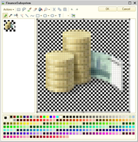
Fig. 667. Image editor
The editor window consists of a toolbar, two fields for editing (the preview field on the left and the field for editing with an enlarged image on the right) and a color palette to select colors from.
The picture can be edited in both fields. You can perform the editing using the mouse. First you need to choose a tool or a shape to draw (pencil, brush, airbrush, line, rectangle or ellipse) and a color using the color palette.
The status bar shows the current position of cursor and the size of the area, as well as the scale.
Images represent a rectangular area consisting of points (pixels), which can be resized by dragging the bottom or right border marker, or the marker of the bottom right corner. Images can also be resized using Image Settings (see below).
Editing process comes to indicating a specific color for each pixel in the image. The number of colors is defined by the image resolution. The higher the resolution, the more colors you can use.
Note. IMPORTANT. Using 24-bit resolution for large images results in an increase of the configuration size.
Colors in the color palette are selected separately for each mouse button. The selected color is indicated by a double frame.
The color composition can be changed. To do so, double-click the color you want to change. Select the color you need from color swatches or create a new color.
The image size can be changed. To do so, drag a marker at the side or corner of the image.
The pixel grid is designed to ease image editing. The grid is shown as a broken line. To setup the display of the grid Actions – Grid. This opens the following dialog box.
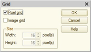
Fig. 668. Grid settings
If Pixel grid checkbox is selected, the pixel grid is displayed.
If Image grid checkbox is selected, it is assumed that the image is a collection of images of the same size (about editing the collection (see section below)). In this case, fields for specifying the collection item size become active. Besides the pixel grid, the collection grid consisting of thin solid lines is displayed in the edit field. In this case, editing mode does not change.
If Image grid checkbox is selected, resizing an image is a multiple of the cell size. If this checkbox is cleared, the image is resized within accuracy of pixel.
Various tools and set of shapes are used for drawing. The set and use of tools are similar to the standard tools set in Paint in Microsoft Windows. Table of shortcuts available in the image editor (see Help menu).
However, there are some differences. By using the Scale button the image of the edit field can be scaled in the range from 1:1 to 20:1 with six selection levels. Click the button to select the next scale level. If the 20:1 scale is reached, pressing the button again selects a 1:1 scale. The required scale can be selected directly by pressing the scale selection button (with a small triangle pointed downward).
If you click the Scale button and move the mouse pointer to any of the image areas, a frame appears. This frame indicates the image area to be displayed when the user clicks on the mouse.
You can also change the scale by holding down the Ctrl key and scrolling your mouse scroll.
Shape buttons (rectangle, rounded rectangle and ellipse) also have selection buttons, by pressing which you can select the shape type (simple, outlined and filled, or filled).
Click Image settings to open the following dialog box:
Fig. 669. Image settings
The image dimensions and resolution (the maximum number of colors used) are set in this dialog box. Alpha-channel cannot be used for images with the resolution 1, 4 or 8 bit/pixel. Only one transparent color can be used. You can use alpha-channel if the resolution is higher than 8 bit/pixel.
Note. Note. It is not recommended to use alpha-channel for images larger than 40,000 pixels (for example, an image with 200x200 pixels). The web client operating in Microsoft Internet Explorer 6.0 does not support the correct display of these images. This rule does not apply to image collections with the items smaller than the specified limits.
The image editor supports standard clipboard commands. Use Ctrl + V to paste an image, Ctrl + C to copy it and Ctrl + X to cut (copy and delete). If an image dimensions exceed the current dimensions, the editor prompts to change it.
There is a multi-purpose button in the toolbar that changes its purpose depending on the selected tool or shape. It is located in the second row on the right, in front of the Image settings button. When the line, curve, rectangle, or ellipse shape is selected, this button indicates thickness of the line used to draw the shape, in pixels. Click the button to consistently change the thickness (five levels). When you click the selection button, you will see a drop-down menu where you can select the desired thickness of the line for drawing the shape. This button sets the size of the airbrush, the size and shape of a brush, and the eraser size. When a selection or text tool is active, this button can be used to set the transparency mode.
Click the Text button to start entering text. The following dialog box opens:
Fig. 670. Text entry dialog box
Add text in the multiline text field. The font, size and other attributes are set using the Font button. The font selection is made from the list of system fonts or from the styles defined in the configuration.
Click Color replacement to replace the color selected by the mouse pointer (indicated by a pixel) with the color set for this mouse button. So, you can quickly change the drawing color using two colors at once on each mouse button.
35.19.3. Image collections
Image collection is an image consisting of individual items (images) of the same size. These items form a rectangular matrix, and each cell of this matrix represents a separate image.
Image collections are designed to simplify the selection of necessary images for controls, column headers, and so on. Using the collection guarantees the choice of images of the same size for the same type of use.
Image editor enables you to create and edit image collections. Select Collection mode to enable the collection edit mode. Selecting this item, you break the image in the preview field into cells. To edit an image item, double-click the cell. The image item will be displayed in the edit field. Editing techniques are described in the section above.
The following buttons are added to the toolbar: Add column and Add row. By clicking these buttons, you can add a new column or a row respectively.
You can change the image size only in the Image settings dialog box only (resize markers are not available).
Fig. 671. Collection settings
The image size in items (cells) is set in the Image settings item group. The cell size in pixels (dots) is set in the Collection settings item group. To configure collection settings, use manifest file attributes of the image with options (see Image manifest).
Image collection can also be edited as a normal image. To do it, it is recommended that you pre-configure displaying the grid by images (see Editing images).
35.20. HTML document editor
35.20.1. General information
This editor offers the major features for editing HTML documents. It can also be used to edit help content for configuration objects.
Fig. 672. HTML document editor
The editor consists of three tabs:
-
Edit. Edit documents in visual mode.
-
Text. Edit documents with HTML markup language. The editor functionality matches the text editor functionality (see Text editor).
-
Preview. Preview the created document but without editing.
35.20.2. Visual editing
35.20.2.1. Formatting text in HTML documents
You can format HTML document text, that is, set its style (font, size, layout, indents, alignment, and so on).
When you copy text from other text editors, such as Microsoft Word, the original text formatting is retained.
35.20.2.2. Inserting and editing tables
You can add tables to HTML documents. To insert a table, click Table – Insert table. In the dialog box that opens, specify the number of rows and columns.
You can add more rows and columns later.
To edit a table (insert and/or delete rows, columns and cells), use the commands from the Table menu of the Designer main menu.
| Menu item | Action |
|---|---|
| Insert row | Add a row above the current one. |
| Delete Row | Delete the current row |
| Insert Column | Insert a column to the right of the current one. |
| Delete Column | Delete the current column |
| Insert Cell | Insert a cell to the left of the current one. Shift the next cells to the right. |
| Delete cell | Delete the current cell. Shift the next cells to the left |
| Merge Cells | Merge the current cell and the cell to the right. The cell contents are also merged. To merge more than two cells, repeat this command as many times as required. |
| Split Cell | Split the current cell into two cells |
Tables can be nested. To add a nested table create a new table in a cell of the existing table.
35.20.2.3. Adding pictures to HTML documents
You can add pictures to HTML documents.
To add a picture, on the main menu, click Element – Picture. In the dialog box that is opened, specify the picture address (a file name and a path) or select a picture file. In the Text field, add alternative text for the image. This text is displayed when you move the pointer over the image.
If necessary, specify image alignment (position in the document) in the Alignment attributes group.
| Alignment value | Description |
|---|---|
| Not specified | Add a picture inside the text, at the pointer position. |
| Left | Add a picture to a new line, aligned with the left document border. |
| Right | Add a picture to a new line, aligned with the right document border. |
| Bottom | Add a picture inside the text, text aligned with the picture bottom. |
| Middle | Add a picture inside the text, text aligned with the picture center. |
| Top | Add a picture inside the text, text aligned with the picture top. |
To add a border, specify its width in the Border dialog box. If the width is 0 or is not specified, the border is not displayed. To insert an image press OK. You can edit the image attributes in the image properties palette.
To move a picture, drag it. To do so, select a picture and drag it to the desired place of the document. The Alignment property does not change. If the alignment is set neither to Left nor Right, you can place the picture inside the text. Otherwise, the picture is placed to a new line.
When inserting pictures in SVG format, if an HTML page does not contain an item of the <meta http-equiv="X-UA-Compatible" content="IE=*"/> type, then an item with the content="IE=Egde" text is added to the page. This item disables the Microsoft Internet Explorer compatibility mode (by default, the page is rendered in compatibility mode with Microsoft Internet Explorer version 7). After adding such an element, the web browser reloads the page without compatibility mode (the current cursor position is lost).
If your computer has Microsoft Internet Explorer version lower than 9, the SVG format image will not be displayed in the HTML editor.
To copy a picture, use the standard operating system tools (the clipboard or dragging while holding down Ctrl).
Picture can be positioned anywhere in the HTML-document (text, spreadsheet, or label).
35.20.2.4. Adding labels
Label is a special HTML document object. It represents the area where you can add some text, table, picture, or other labels. When you view a label, included objects are continuously scrolled from right to left.
To insert a label, click Element – Label.
To resize a label, select it and drag its marker.
You can add labels to a text and tables.
35.20.2.5. Adding hyperlinks
Links are used to create a hyperlink in HTML documents.
To add a hyperlink, select a text or a picture object and then, on the main menu, click Element – Link. This opens the hyperlink properties dialog box.
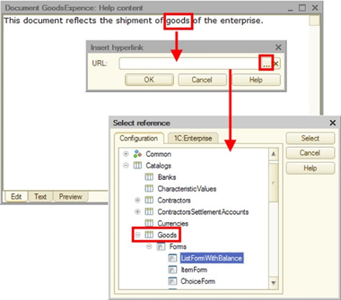
Fig. 673. Adding a hyperlink
The Address attribute should specify:
-
The hyperlink address.
-
Reference to help information on the configuration object.
-
Reference to the system help section. If Managed application is selected as the configuration editing mode, only those help sections associated with managed application are displayed (together with the column that describes availability of this section in the web client). If Managed application and ordinary application is selected as the configuration editing mode, all help sections are displayed with the information about the section availability in managed application, web client and ordinary application.
-
Tab name (preceded by the "#" character).
To create a link, click OK.
By default, hyperlinks appear blue with a blue underline. Blue border is added to a picture.
35.20.2.6. Adding bookmarks
Bookmarks are used to create cross-references in HTML documents. To do this, select a text or a picture object and go to Elements – Bookmark. Dialog box for entering the bookmark name appears on the screen. The formatting of the selected object is not changed.
Bookmarks are used to organize internal links.
35.20.2.7. Adding horizontal lines
Horizontal lines serve as separators.
35.20.3. Editing HTML document source code
Features of the HTML document editor listed on the Edit tab are limited. You can edit HTML document source code on the Text tab.
Please remember that manual encoding changes using thecharset attribute of the META tag do not affect the editor behavior. When saving the HTML document, it will be written in UTF-8 encoding with the unchanged charset tag. When reading the document, the charset tag will be set to utf-8.
35.20.4. Previewing HTML documents
To preview the HTML document after editing, go to the Preview tab and test the document objects.
35.21. Configuration localization
Configuration localization means translating 1C:Enterprise system string values into languages specified in the Common – Languages branch of the configuration tree. String values can include names of interface items, names (synonyms) of objects, reference information, module texts, and so on.
The most difficult part of this work is finding the places where the text is to be added in the required language. That is why, you can use this mode even when only one language is set.
To start searching, use the Edit – Edit interface texts command.
The following dialog box opens:
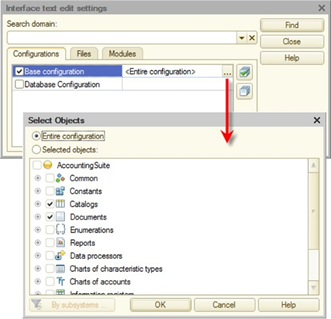
Fig. 674. Editing interface texts
On the Configurations tab, select configuration objects for editing interface texts.
The configuration list includes all open configuration windows (in addition to the basic configuration, these can include database configuration, configuration files, repository and vendor configurations).
You can select Entire configuration line to create a full list of configuration objects containing interface properties. You can perform search only amid specific objects, if you select this object in the selection field.
Use the Files tab to select text and spreadsheet documents as well as external data processors stored in files.
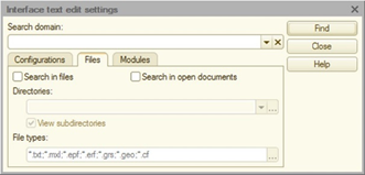
Fig. 675. Setting up search in files
On the Modules tab select the Search in the "NStr" functions in the modules if you want to determine where the NStr() operator is used in the modules. When selecting this checkbox, please remember that the NStr() operator is processed without parsing. So, the NStr() operators in the comments will also be processed. If the lines in different languages include line breaks, the comment mark (//) before such ("added") lines will not be added.
To remember the search parameters (list of configuration objects, files and open documents), specify a name for the current settings in the Search scope attribute. If you reopen the search window in the list of scopes, select the desired one and perform a search.
Select the objects you need and click Find. This opens the following window:
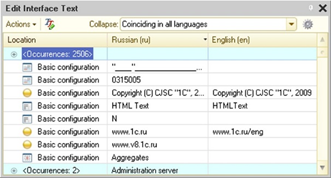
Fig. 676. Search results window
The window contains a table box, the first column of which shows the location of the text found. Other columns are usually used for the specified languages. The table box can have more columns than the number of languages specified. Additional columns appear when new Language objects are created in the configuration process and then deleted, or their language code is changed. When the language code is deleted or changed, Designer does not reset the interface text for these languages.
Table box content is sorted by one of the columns. Click the column header to change the sorting. Click the header again to change the sorting direction.
Text can be edited directly in cells. To do this, select a cell and press Enter. Text box opens in the edit mode. Add the text you need and press Enter again. The modified text is shown in red.
For quick access to the interface text for a specific object, double-click the required line in the Location column. A form with this text is displayed. You can also view and replace the found text in the property palette. If the text has been modified outside the editing window, you can refresh the table field.
Above the table field, you can find controls for performing actions and setting up the window.
Use the Collapse selection field to specify the text collapse mode for different languages. If the value None is selected, the text is not collapsed. If Matching in sorting language is selected, then all items with the same text in a sorting column are collapsed. The first column contains the group icon (+). Click the icon to expand the group. The first column will show the text <Occurrences N> (where N is the number of item occurrences). If other columns of this group have different text values, then the cell in these columns will contain <Different values> text.
If Matching in all languages is selected, all items with the same text are collapsed.
You can perform group text replacement for collapsed rows. To do so, add the text into the appropriate language cell, as if it would be one string. The added text replaces the text at once in all the lines belonging to the group.
Use Actions – New search to open the setup window to customize configuration sections to be searched.
Use Actions – Copy texts to copy all texts in one language to a different language. It is recommended to use this operation when words and phrases in different languages are basically the same.
Use Actions – Clear texts to clear all texts in the specified language.
Use Actions – Fill texts to translate synonyms, headers, tooltips, and interface texts in real time using a mapping file. This represents a spreadsheet document with several columns (according to the number of languages used).
First row of each column must contain a language code, for example, en or lv. Other rows contain mapping samples. No ordering (sorting) requirements are applied. Rows can be duplicated.
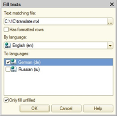
Fig. 677. Filling texts
After selecting the mapping file, specify the default language (By language) and the languages for which translation is required (To languages). Selecting Fill blank only checkbox locks the overwriting of already translated strings.
Key language and languages for filling are selected from the languages that were found during interface text search. All languages selected for filling must be defined in the mapping file (it should contain columns with headers corresponding to these languages codes).
Note. Note. If strings in only one language are found when you open the Edit interface text window, the Fill texts command will be unavailable.
Click OK to fill the interface text. The texts are filled not only according to the key language mapping but also according to all language mappings that are present in the mapping file.
This can be used to specify a one-to-many correspondence between strings (so that identical strings are translated to the same language differently). To do so, in a two-language configuration add a third auxiliary language for commenting user interface texts and write different comments for the key language homonyms. For example, Account word may have different comments in Russian: "financial account" and "invoice". You can use it to map the first word with "Account" and the second word with "Invoice".
Use Actions – Export to spreadsheet to export the table field content to a spreadsheet document. Executing the command displays only unique strings.
Use Actions – Settings to set up a table field view mode and editor opening mode for group replacement.
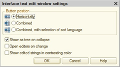
Fig. 678. Customizing interface text editing window
The Column position group is used to select a mode for column arrangement:
-
Horizontally. As it is shown in fig. 678.
-
Combined. Columns are arranged one below the other.
-
Combined, with selection of sort language. Columns are arranged as follows: a column with the sort language is placed to the right of the Location column and columns with other languages are placed one below the other further to the right. When you click the header of a column, this column is sorted, and it is located to the right of the Location column. The column used for sorting replaces the selected column. If there are only two languages, the columns simply change places.
If the Show as tree on collapse option is checked, you can access collapsed rows, and collapsed groups are shown as a tree.
It is recommended not to check the Open editors on group replacement option if there are many occurrences.
If Show edited strings in different color checkbox is selected, the modified text in the strings will be shown in a different color.
35.22. Centralized configuration verification
To verify a configuration, click Configuration – Configuration verification. This opens the following window:
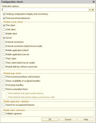
Fig. 679. Configuration check
Let us consider how configuration is verified in more detail. Any application code in 1C:Enterprise is executed in some environment. This environment is characterized by a certain set of defined preprocessor commands (see Preprocessor commands) and a set of available objects. Respectively, when the configuration is checked, Designer defines preprocessor commands for every checked item and performs a validation. Note that if a client application is tested in the client/server mode, the entire application code is checked on the client side. On the server side, only common modules available for calling from the client application are checked. If a common module exists in the application being tested and is delivered without source texts, then during the configuration check all method calls of this general module will be marked as a possible error. To execute checks using this dialog box, you can use the /CheckConfig command of the command line for Designer batch startup.
Since there are a lot of operating modes, validations are divided into two groups:
-
Validations available for forced and automatic check when configuration is edited. You can select these modes on the Modules – Check tab of the Designer settings dialog box (see Setting module check parameters).
-
Complete list of validations that can be called at the central configuration check (the mode is being described).
For each module syntax check mode to be specified in the dialog box, the following objects will be described:
-
Preprocessor commands that will be defined if you select this check mode.
-
Control features (if any).
-
The /CheckConfig command parameter that will allow you to execute a similar check.
Besides, there will be a description for check modes that are not related to module syntax check but allow executing various auxiliary checks. For these check modes, the /CheckConfig command parameters, which you can use for command line check, will also be specified.
See also:
- The /CheckConfig command of the command line for Designer batch startup.
General parameters
Verifying configuration integrity and consistency
It is a standard check that is usually performed before updating the database.This check deletes incorrect data that could have been added to the configuration after editing the previous versions of the system./CheckConfig command parameter: ConfigLogIntegrity.
Search for invalid references
Search references to deleted objects. The search is performed in the entire configuration, including forms, templates, interfaces, and so on. It also searches for incorrect references to predefined data for charts of accounts (if the Extra Dimension Types property is set for the chart of accounts) and charts of calculation types./CheckConfig command parameter: IncorrectReferences.
Module syntax check
Thin client
Verifies the module compilation while checking the Thin client environment in the managed application mode (executed in the file mode).The following preprocessor commands are defined: Client, AtClient, and ThinClient.
/CheckConfig command parameter: ThinClient.
Web client
Verifies the module compilation while checking the Web client environment in the managed application mode (executed in the file mode).The following preprocessor commands are defined: Client, AtClient, and WebClient.
/CheckConfig command parameter: WebClient.
Mobile client
Verifies the module compilation in the Mobile client environment check mode.The following preprocessor commands are defined: Client, AtClient, and MobileClient.
/CheckConfig command parameter: MobileClient.
Mobile client (in standalone mode) and mobile standalone server
Verifies the module compilation for an offline configuration. Two checks are performed with different preprocessor commands:
-
First check: Client, AtClient, and MobileClient.
-
Second check: Server, AtServer, and MobileStandaloneServer.
/CheckConfig command parameter: MobileClientStandalone.
Server
Verifies the module compilation in the 1C:Enterprise server environment check mode.
The following preprocessor commands are defined: Server and AtServer.
/CheckConfig command parameter: Server.
External connection
Verifies the module compilation in the external connection environment check mode (executed in the file mode).
The following preprocessor commands are defined: ExternalConnection and Server.
/CheckConfig command parameter: ExternalConnection.
External connection (client/server mode)
Verifies the module compilation in the external connection environment check mode (executed in the client/server mode).
The following preprocessor commands are defined: ExternalConnection.
/CheckConfig command parameter: ExternalConnectionServer.
Mobile application client
Verifies the module compilation in the client application environment check mode executed on the mobile platform.The following preprocessor commands are defined: Client, AtClient, and MobileAppClient.
/CheckConfig command parameter: MobileAppClient.
Mobile application server
Verifies the module compilation in the client application environment check mode executed on the mobile platform.The following preprocessor commands are defined: Server, AtServer, and MobileAppServer.
/CheckConfig command parameter: MobileAppServer.
Thick client
Verifies the module compilation while checking the managed client environment (executed in the file mode).If the Use ordinary forms in managed application configuration property is set to False, the ordinary form modules are not checked when you select this test.
The following preprocessor commands are defined: Client, AtClient, ThickClientManagedApplication, Server, and AtServer.
/CheckConfig command parameter: ThickClientManagedApplication.
Thick client (client/server mode)
Verifies the module compilation while checking the managed client environment (executed in the client/server mode).
If the Use ordinary forms in managed application configuration property is set to False, the ordinary form modules are not checked when you select this test.
The following preprocessor commands are defined: Client, AtClient, and ThickClientManagedApplication.
/CheckConfig command parameter: ThickClientServerManagedApplication.
Module distribution without source text
If the configuration distribution settings for some modules specify distribution without source text, the capability to generate module images is checked./CheckConfig command parameter: DistributiveModules.
Logical module check
Search for unused procedures and functionsSearch for local (not exported) procedures and functions that are never referenced, Including unused event handlers.
The form module procedure or function is considered used if its name can be found in the "ProcedureName" form (including double quotes). In other words, it is considered used if it is a parameter of any method, for example, an event handler assignment.
/CheckConfig command parameter: UnreferenceProcedures.
Check availability of assigned handlers
Checks availability of event handlers for interface, forms, controls, and flowchart items./CheckConfig command parameter: HandlersExistence.
Search for empty handlers
Search for event handlers that perform no actions. Such handlers can impact the system performance./CheckConfig command parameter: EmptyHandlers.
Extended check
For a restricted set of types, calls of object methods and properties are checked "over the period". Also, a check is conducted to determine whether the settings specified by a string are correct for a limited number of methods. Messages that are formed as a result of the extended module check do not contain the line numbers with the detected problems./CheckConfig command parameter: ExtendedModulesCheck.
Search for modality use
This checkbox is only available if extended configuration verification is enabled. In this mode Designer searches in modules for methods to open modal dialog boxes. The Modality use mode configuration property does not affect the verification mechanism. If you select this checkbox, errors are generated even if the Modality use mode property is set to Use or Use with warning./CheckConfig command parameter: CheckUseModality, but only together with the ExtendedModulesCheck parameter.
Search for use of synchronous calls
This checkbox is only available if extended configuration verification is enabled. In this mode, Designer searches in modules for code fragments in 1C:Enterprise language that use synchronous calls. The Synchronous calls to platform extensions and external components use mode configuration property does not affect the verification mechanism. If you select this checkbox, errors are generated even if the Modality use mode property is set to Use or Use with warning.
For more information about synchronous call features, see Analysis of legacy synchronous configuration calls.
/CheckConfig command parameter: CheckUseSynchronousCalls, but only together with the ExtendedModulesCheck parameter.
Mobile application validation
Search for unsupported features
The check in this mode shows that:-
Configuration objects that are not implemented for the mobile platform are available.
-
Exchange plans with the Distributed infobase property set are available.
-
Configuration objects that are not supported by the mobile platform are used:
-
In the Type properties of configuration object attributes, constants, and session parameters
-
In the Command parameter type property of the Command object
-
In the Type property of attributes and form attribute columns
-
-
Non-managed forms are available.
-
Form items that are not supported by the mobile platform are available. This check is not performed for forms whose Use purposes property does not include mobile devices.
-
Home page consists of no more than one form.
/CheckConfig command parameter: UnsupportedFunctional.
Mobile client validation
Signature verification
Verifies digital signature of the configuration for the mobile client.
/CheckConfig command parameter: MobileClientDigiSign.
You can save the selected settings composition for further use. To do that, specify the name for the set of settings in the Verification settings field. To switch to a previously saved assortment of settings, select a name in this field.
All error messages are displayed in the message window. To terminate the configuration check, press Ctrl + Break or Ctrl + Alt + E.
Note. Note. Interrupting a configuration check can be processed with a delay at the initial stage of the check.
When the configuration connected to the repository is being checked, it is recommended to lock the configuration root object in order to avoid errors related to metadata information.
If the Edit configuration for startup modes parameter (see Overall) is set to Managed application and ordinary application, the following parameters are added to the dialog box:
-
Thick client (ordinary application)
-
Thick client (ordinary application, client/server mode).
At that, the dialog box looks like follows:
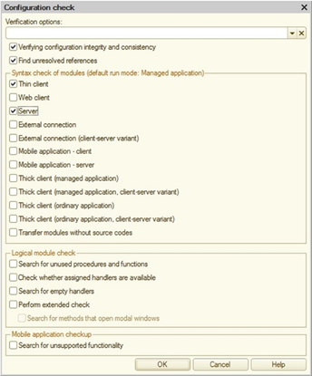
Fig. 680. Configuration check
These tests are described below.
Thick client (ordinary application)
Verifies the module compilation in the external connection environment check mode (executed in the file mode).
If the Use managed forms in ordinary application configuration property is set to False, the managed form modules and command modules are not checked when you select this test. The form module specified in the Default Constants Form property is checked if this test is selected regardless of the Use managed forms in ordinary application property value.
The following preprocessor commands are defined: Client, AtClient, ThickClientOrdinaryApplication, Server, and AtServer.
/CheckConfig command parameter: ThickClientOrdinaryApplication.
Thick client (ordinary application, client/server mode)
Verifies the module compilation while checking the client application environment, executed in the client/server mode.
If the Use managed forms in ordinary application configuration property is set to False, the managed form modules and command modules are not checked when you select this test. The form module specified in theDefault constants form property is checked if this test is selected, regardless of the Use managed forms in ordinary application property value.
The following preprocessor commands are defined:Client, AtClient, and ThickClientOrdinaryApplication.
/CheckConfig command parameter: ThickClientServerOrdinaryApplication.
Chapter 36. Comparing and merging configurations
36.1. General information
You can use the configuration comparing and merging mode to compare two configurations in detail and to merge them. Selective merging based on the comparison results is also possible. Compare and merge of main configuration and configuration extensions are not supported.
You can use the merging mode, for example, when one configuration is developed by several persons at the same time. Sometimes they need to merge the results of their work or merge all results at the end of development.
The configuration comparison and merging mode can also be used to compare two configurations without merging.
Eventually, if you need to upload changes to the source configuration, you should review and evaluate them using compare and merge configurations mode.
This mode compares both common properties of configuration objects such as catalogs, documents and logs, and individual objects and table attributes. The following object forms are compared separately: modules, description texts, and templates. You can view the comparison results in details as well.
36.2. Configuration comparison conditions
When the comparison mode is activated, the program analyzes the configurations and maps the objects.
Objects without a match can be either new or deleted objects or they may be objects from the same category but named differently in different applications. You can configure interactive mapping for these objects (see Mapping objects).
During the automatic mapping, the program analyzes configuration objects with the same names. For example, Catalog.Goods in one configuration and Catalog.Goods in another configuration are considered the same catalog. They are mapped and compared.
Objects with different names are compared by internal IDs assigned by Designer upon their creation. Internal IDs are required to simplify mapping of configuration objects and make it automatic. This situation may occur when the object name changes during configuration development. If object names are different while their internal IDs match, these objects are automatically mapped.
Form mapping is performed in a special way. A form can contain several pages. First forms are analyzed by names, then pages with different names are analyzed by (non-blank) headers, and then pages with different headers are analyzed by pictures. If pages are mapped, their controls are compared and merged. If pages could not be mapped, they are considered different and the result form (after the merge) contains all these pages separately.
Pages that have none of the three properties set (Internal ID, Header and Picture) are merged by pairs in accordance with the selected sequence order.
36.3. Starting the configuration comparison and merging mode
As you can see further below, although compared configurations can be considered as basically equal (when merging, you can give priority to any of them), in a certain aspect the current configuration is considered as the main configuration, and non-damaging changes are introduced to it from the loaded configuration. Based on these considerations, it is recommended to choose which of the two configurations is to be made the main one. The selected configuration becomes the main configuration when 1C:Enterprise starts up in Designer mode.
Before comparing and merging the loaded configuration with the main configuration, you have to save it to a file first (see Saving configurations to files).
To load the second configuration, use the Configuration – Compare and merge with configuration from file... command. The standard Select a configuration file dialog box will appear. Find and open the file of the loaded configuration with the (*.cf) extension in this dialog box.
If the main configuration is blank (the application development has not yet begun), Designer prompts the user to perform the configuration full boot. Upon the user confirmation, it proceeds to full boot of the configuration and the Configuration window opens. Upon cancellation of full boot, the configurations are compared.
Designer status bar displays messages during the process of loading and comparing of the loaded configuration with the main configuration. These messages show configuration objects that are being currently compared. The status bar also displays a comparison progress indicator.
Loading and comparing can take a lot of time. It depends on the size of the compared configurations.
36.4. Comparing configurations
In addition to the basic configuration comparison and merging mode described in the previous section (when one of the compared configurations is always set as the main configuration), Designer can compare two arbitrary configurations (for example, configuration files) or repository configuration (any version) and vendor configuration, and so on.
Configurations to be compared can be selected in the Configuration – Compare configurations menu.
The following dialog box opens:
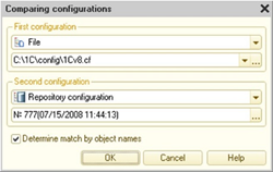
Fig. 681. Comparing configurations
The dialog box contains two sections to select the configurations to be compared. Techniques used in both sections are the same. You can select the following configurations to be compared:
-
Main configuration
-
Vendor configuration (if the current configuration is supported)
-
Database configuration
-
Repository configuration version (if the main configuration is connected to the configuration repository)
-
Configuration extension
-
Configuration extension stored in the database
-
Configuration extension version from the repository (if the configuration extension is connected to the configuration repository)
-
Configuration or configuration extension in a file
If a file is selected as one of the compared configurations, the field is provided in the dialog box to select a configuration file (extension .cf) or extension configuration file (extension .cfe).
If the option chosen for comparison is related to the configuration extension and several extensions are connected to the database, it is necessary to select a specific extension.
If a version of the main configuration or extension is selected for comparison from the repository, select the version of the repository to be compared with.
If the compared configurations are not descendants of each other and therefore they cannot be matched by internal IDs, the Set matching by object names checkbox should be selected. Click OK to start file comparison. Designer will compare the specified configurations and display the result of the comparison in the Compare configurations window. Techniques used in this window are the same as described in the "Comparing and merging configurations" section, with the only difference that in the comparison mode you can only view the selected objects and get a report on the differences.
36.5. "Compare and merge configurations" window
After the comparison procedure is completed, the Merge configurations window is displayed. This window can be used to do the following:
-
Learn which objects in the two configurations are different.
-
Select the objects that require a detailed review of differences.
-
Call the specified objects for viewing and editing.
-
Specify the objects to be merged.
-
Map objects.
-
Set the configuration merging modes (for the entire configuration or for each object).
-
Set the order of subordinate objects (for the entire configuration or for each object).
-
Generate a report on the configuration differences.
-
Initiate the configuration merge procedure.
The window (see fig. 682) contains a table box that consists of three columns if the configurations are not linked with each other. For more information on linked configurations, see Configuration comparison setting. The first column contains a color mark indicating that the merge settings are different from the default settings. The objects with the merge settings different from the default settings are marked in green, and an object, slave objects of which have merge settings different from the default settings, is marked in light green color. The second column contains information about the main configuration (the infobase that is opened in Designer), information about the loaded configuration is in the third column, and the last column is used to set the merging mode and the order of subordinate objects.
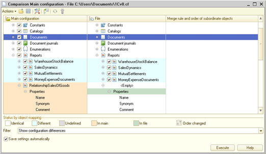
Fig. 682. Comparing and merging configuration
The background color of the lines is an indication of objects difference (matching status). The possible statuses are listed under the tabular field.
Below the status details is the Filter selection field that is used to set the view changes mode. When you open the Merge configurations window, the Show configuration differences filter is set. Selecting other modes allows you to explore differences in configurations or matches.
All operations that are available in this window, except for merging (the Run button), are located in the command panel of the form. The following commands are available:
-
Search for ambiguous references to objects to be deleted. Searches for ambiguous references to objects to be deleted. The results are displayed in a message box (with the possibility of positioning on the property containing the link).
-
Load settings.... The window settings are reset to the default settings, and then the merge settings from the file are loaded. The downloaded file becomes the current one to run the save command and automatically save the settings.
-
Add settings.... The file settings complement the current merge settings set in the window. In this case, the file to add the settings from will not be used to save settings (including automatically).
-
Save settings. Allows you to save to a file the selected objects, the merge properties and modes, and the merge settings for modules, forms and spreadsheet documents. Only those merge settings that are different from the default settings are saved. Saving is available if the current merge settings include settings that differ from the default settings.
-
Save settings as.... It is similar to the Save settings command, but offers to change the file to which the settings will be saved.
-
Set default settings. The current window settings are reset and the default settings are set for the compare/merge window. These settings are applied at the opening of a dialog box.
-
Merge modules. Performs merging of selected non-merged modules, which have been set one of the Merge with priority ... modes.
-
Update. Update comparison tree after changing configuration objects.
-
Set mode for all. Opens the dialog box for setting the merging mode and setting the order (see Subordinate object order setting) for all objects.
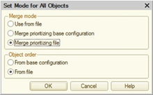
Fig. 683. Setting modes for all objects
-
Mark by subsystems.... Allows you to set the selection by subsystems of the main configuration or file configuration.
-
Comparison report. Allows you to get a report on the comparison of two configurations with the necessary detail level.
-
Settings. Opens the form to set up the compare/merge settings (see Configuration comparison setting).
The Save settings automatically checkbox controls the automatic saving of the compare/merge window settings before the merge starts (by pressing the Run button).
Before closing the compare/merge window, you will be prompted if you want to save the settings to a file if they differ from the default settings and have not been saved.
Note. Note. When the compare/merge configurations window is open, it is not recommended to perform lengthy operations on the configuration, for example, operations with repository, disabling support of the vendor configuration, and so on.
36.6. Configuration comparison setting
36.6.1. General information
Clicking the Settings button opens the Configuration comparison setting dialog box.
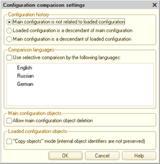
Fig. 684. Configuration comparison setting
In the dialog, the configuration comparison mode is selected. The default mode is comparison of various configurations (not related to each other).
If the configurations are related, you need to select the nature of the connection. When you close the settings dialog box (clicking the OK button), a special text box is added to the Merge configuration window, with the history of object changes shown by special icons.
A special text box is added to the Loaded configuration column if the loaded configuration is a descendant of the main configuration. It is added to the Main configuration column if the main configuration is a descendant of the loaded configuration.
Also, the reference information is added to the window for description of statuses grouped in the Status group on the object history.
If the configuration uses several languages, selective comparison by languages is available. Select the Use selective comparison by languages checkbox and specify one or more languages to be compared.
36.6.2. "Main configuration objects" group
When configurations are being merged, objects of the main configurations can be deleted. By default, this feature is only enabled in the vendor configuration update mode. To enable it in other modes, select the Allow main configuration objects deletion checkbox.
By default, deletion marks for vendor objects are set based on the following rules. If the user has modified a vendor object as compared to the previous version of vendor configuration, the object is not marked for deletion by default. If the object is identical to its previous version, it is marked for deletion. If an object has been marked for deletion (automatically or manually), clicking the Run button results in reference integrity check. If ambiguous references to a deleted object have been found, they are displayed in a separate window. However, unlike the case of ambiguous references resulting from a canceled copying of a vendor configuration object (or any other configuration being merged), you cannot continue merging (and delete the object) in this case.
36.6.3. "Loaded configuration objects" group
By default, upon merging of configurations, the objects unavailable in the main configuration are added to it together with IDs assigned to them in the loaded configuration.
Selecting the Object copying mode... checkbox adds new objects according to the rules that existed in the previous platform versions: when adding objects that did not exist in the main configuration, new IDs are always generated for them.
When you press the OK button, the repeated comparisons based on the selected setting is performed.
36.7. Editing objects
When the Merge configurations window is open in the standard mode (repository is not used and no support is available), you can view and edit objects in the main configuration.
To edit object properties, specify the required object in the column of the main configuration and correct the value in the properties palette. If the edited object is a form, template, interface, or another complex object, it can be opened for editing by selecting the Open form (Template/Interface) command from the context menu. The main configuration objects can also be selected for editing in the Configuration window.
The loaded configuration objects are available for viewing only. The procedure for accessing the loaded configuration objects is similar to the procedure for accessing the main configuration objects.
In case any changes have been made, the Run button becomes unavailable and all objects are assigned the Undefined status (displayed in gray). Click the Refresh button to keep working in the Merge configurations window. Designer re-compares the configurations (considering the changes made) and maps objects.
36.8. Editing features of distributed development and support
In the distributed development mode, you can only edit the main configuration objects locked in the repository using the Merge configuration window.
Objects not allowed for editing can only be viewed. These objects cannot be selected for the merge (no checkbox is available).
A "closed lock" icon to the left of the object icon indicates that no editing is allowed. In addition, the status of the object is displayed under the table field, with a text message prohibiting editing.
The Merge configuration window behaves similarly if the configuration is supported. If a vendor rule prohibiting change is set for a specific object, this object is available only for viewing. These objects can only be compared, and cannot be merged.
36.9. Mapping objects
When configurations are compared, the program automatically maps objects of the two configurations. Since objects are mapped based on their names, the object names can be identical in the configurations being compared. However, the objects may in fact be different. On the other hand, the objects with different names might be the same. In such cases you should map the objects manually.
To cancel mapping, select an object and choose the Clear object mapping command from the context menu. The status of these objects changes to Undefined. Click Refresh when mapping is cleared for all such objects. Designer will re-compare configurations.
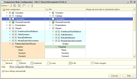
Fig. 685. Compare/Merge configurations main window
For the main configuration, the objects are shown with a beige background (available only in the main configuration). Objects of the loaded configuration have the green background (available only in the loaded configuration).
To map the object, select it and the Map objects item from the context menu. The list of the objects that are available for mapping is displayed. The list includes objects of the same type and objects that have not yet been mapped. Select the object and press OK.
36.10. Comparison and merging features
36.10.1. General information
The merging mode can be set for each object to be merged. There are two types of modes:
-
Retrieve from the loaded configuration (depending on the loaded configuration, the name of the merging mode may differ). If you select this mode, then the configuration object is added (if it is new), or replaced (if it is modified). Moreover, the entire structure of the object, modules, descriptions, forms are migrated. Priority is given to the loaded configuration.
-
Merge with priority .... In this case, the priority of configurations is usually specified when merging. Selecting Merge with priority of main configuration means that only new items should be taken from the loaded configuration, and old ones should be kept.
Selecting the merging mode for some objects (or attributes of objects) may be unavailable, or it may have a limited choice of merging options.
36.10.2. Text documents (including source code)
Texts are merged as follows:
| Text | Priority | Result |
|---|---|---|
| Deleted (available in main configuration, and not available in loadable configuration) | With main priority | Saved in text |
| New (available in loadable configuration and not available in main configuration) | Added | |
| Modified | Added as comments from the loaded configuration, while the main configuration items remain unchanged | |
| Deleted | With loaded priority | Turns into comments |
| New | Added | |
| Modified | Changes in the main configuration are turned into comments. Changes in the loaded configuration are added |
Priority choice for a module with source text can be illustrated as follows.
Text in the main configuration module:
Procedure SpecifyStatus(Item)
// Insert handler contents
Message("Message from the main configuration");
EndProcedureText in the loaded configuration module:
Procedure SpecifyStatus(Item)
// Insert handler contents
Message("Message from the loaded configuration");
EndProcedureResult of merging with the main configuration priority:
Procedure SpecifyStatus(Item)
// Insert handler contents
//{{MRG[ < > ]
Message("Message from the main configuration");
//{{MRG[ < > ]
//{{MRG[ < > ]
// Message("Message from the loaded
configuration");
//{{MRG[ < > ]
EndProcedureResult of merging with the loaded configuration priority:
Procedure SpecifyStatus(Item)
// Insert handler contents
//{{MRG[ < > ]
Message("Message from the loaded configuration");
//{{MRG[ < > ]
//{{MRG[ < > ]
// Message("Message from the main
configuration");
//{{MRG[ < > ]
EndProcedureIf modules are merged using an external program (see Comparison/merging), the result of the merge depends on the external program used.
36.10.3. Managed forms
When managed forms are merged, visualization of differences in the Merge configurations window is not supported, but the results of the form comparison can be displayed in the text format, in a report on object comparison. When comparing forms, mapping is performed according to the following rules:
-
Module texts are compared by procedure names.
-
Form elements are compared by item type and name.
-
Form settings are compared by name.
-
Commands are compared by name.
-
Attributes are compared by name.
-
For the command interface, comparison is performed by command type (automatic or custom) and command name.
The matching items (with the same names) in the main form are to be replaced (the properties, sizes and dimensions) if priority has been set for the loaded configuration. They are left unchanged if priority is set for the main form. Some form item properties can be merged (for example, a selection list, headers in different languages, and so on).
The form merging mode can be configured both for the entire form (both for the form and the form module), for managed and ordinary forms, and for the form and its module separately, for managed forms only:
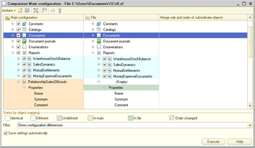
Fig. 686. Form merging setting
To set a single rule for a managed form and its module, you need to use the context menu of the form for which you want to set a rule. In the context menu that opens, select the required item from the Merging mode for subordinate objects submenu.
By clicking on the gear icon in a special column, you can open the module comparing (or merging) window (see Comparing and merging modules). Depending on the Designer settings (see Comparison/merging), either the tool built into Designer, or an external program will be used for this operation. If the gear icon with a green mark is located in this column, this means that the user has configured the merge settings in this module. When you click on such a picture, 1C:Enterprise editor is opened to refine the result of merging with an external program. The editor capabilities in this window are equivalent to the capabilities of the built-in editor when comparing and merging modules (see Comparing and merging modules). If you need to re-configure the merging setup in an external program, then you should use the Show differences in modules command in the context menu. If the gear icon with an exclamation mark is displayed in the column, this means that there are unresolved merge conflicts when performing a merge using an external program (only for the updating of supported configuration).
Some actions that can be performed in the compare and merge configuration window depend on the Designer settings (see Comparison/merging):
-
The context menu command Show differences in modules:
-
Designer settings: Two configurations merge settings
-
External program settings: Merging two files
-
The result is ignored.
-
-
The Show differences in modules irregardless the structure context menu command:
-
Designer settings: Show differences without structure
-
External program settings: Comparing two files
-
The result is ignored.
-
-
The context menu command Module merge settings:
-
Designer settings: Two configurations merge settings
-
External program settings: Merging two files
-
The result is used as the merge result.
-
When calling a command, the tool specified in the corresponding Designer settings will be used, and if any external program is selected as a tool, the command line specified in the corresponding external program settings will be used to perform the action. If the built-in Designer tool is used for the selected action, then editing the result of merging is unavailable when performing the comparison.
36.10.4. Comparing predefined data
When predefined data are compared, their items are mapped only by internal IDs.
Upon creation of a predefined item, it is assigned a unique ID (within a metadata object). This ID remains intact during any migration of the predefined data between configurations when the configurations are merged or copied. This way the ID behavior is different from that of the corresponding ID of the metadata object. So, if you create predefined data items with the same name in two configurations, these items are considered different during comparison. The only way to obtain identical predefined data in two configurations is to merge or copy. If the merging must result in the creation of several predefined elements with the same name in the resulting configuration, a numeric suffix is added to the element from the non-priority configuration (the predefined element name is changed). A diagnostic message will be displayed in the message window.
When a database configuration is updated, predefined items are mapped with existing database objects. Internal ID immutability ensures correct connection between the predefined data element and its mapped database object during migrations between configurations. Replacement of mapped objects will be made in accordance with the choice of priority configuration.
Due to the fact that mapping is performed on internal IDs, predefined data for hierarchical structures can merge, even if they are at different levels of the hierarchy. The result of the merge (the level of the hierarchy where the merge item is) depends on the configurations priority.
36.10.5. Comparing configuration extensions
The compare and merge extension operation is supported for:
-
Configuration extensions saved in a file (*.cfe).
-
Configuration extensions saved in the infobase.
Any options of comparison and merging of the main configuration and configuration extension are not supported.
There is an option to manually map objects of the compared extensions.
When comparing adopted objects, both the values of the objects and controllability property are considered. Differences in the object values and differences in controllability are included in the comparison report. At the same time, if you compare native and adopted objects, then only the object value is checked, without controllability option.
When merging properties of objects, the following features should be considered:
-
The Object type property is displayed, but is not available for customization.
-
For objects with a controllability flag set, the merge is performed as follows:
-
For the "native adopted" pair, values are merged and the controllability flag is not used.
-
For the "adopted native" pair, values are merged and the controllability flag is not changed.
-
For the "adopted – adopted" pair, values are merged and the controllability flag is obtained from the configuration being merged with.
-
-
The saved form is considered a single object, and any actions with it depend on the merging mode:
-
The merge is performed with the priority of the configuration extension. The saved form does not change.
-
The merge is performed with the file priority. The saved form is retrieved from the file.
-
36.10.6. Data types
For attribute types, including the type components in a chart of characteristic types and the components of the type being defined, you can specify both the automatic merging mode for the type components, and use the manual setting of the merge rules. When specifying a merge with priority, the merge is performed as follows:
-
If at least in one configuration the attribute has a union type specified, then the result is the merge of the union type. The resulting type contains types from both configurations. Rules for the type qualifiers merge are described further in this section.
-
If the object has a simple (not union) type in both configurations, then the result is the type from the priority configuration.
-
If in one of the type configurations consists of a type that cannot be part of a union type, the type will be entirely taken from the priority configuration.
When merging two identical types that differ only in qualifiers, the following rules are applied:
-
For the Date type, the qualifiers from the priority configuration are used.
-
For the String type, the following rule is used:
-
If both qualifiers have a fixed string length, then the resulting qualifier has the maximum length.
-
If both qualifiers have a variable string length, the resulting qualifier has the maximum length.
-
If one of the types is a string of unlimited length, then the resulting type is acquired from the priority configuration.
-
In other cases, the resulting qualifier is acquired from the priority configuration.
-
-
For the Number type:
-
If both qualifiers accuracy value coincides, and the value of the Non-negative property is the same, then the resulting qualifier has the maximum length value.
-
In other cases, the resulting qualifier is acquired from the priority configuration.
-
When comparing and merging various types, you can control the merge manually. To do this, click the gear icon for the selected type.
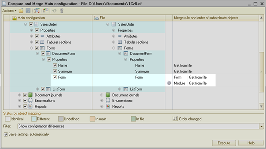
Fig. 687. Opening the type merge settings
Then, the types merge setup dialog opens. This dialog displays information on the types to be merged.
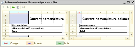
Fig. 688. Type merging setting
You can specify a filter for the displayed list (the Filter field). The result of merging for each type is displayed under the list of the merged types. To see the result of merging, move the cursor to the corresponding line in the dialog.
36.10.7. Exchange plans, subsystems, and functional options
When merging configurations, the resulting contents of exchange plans, subsystems and functional options is formed by merging the contents of these merge objects.
Upon merging, the autoregistration flag of an exchange plan contents element is acquired from the priority configuration.
If you need to manually configure the merge of the contents of exchange plans, subsystems or functional options, you should click the gear button for the desired Contents property.
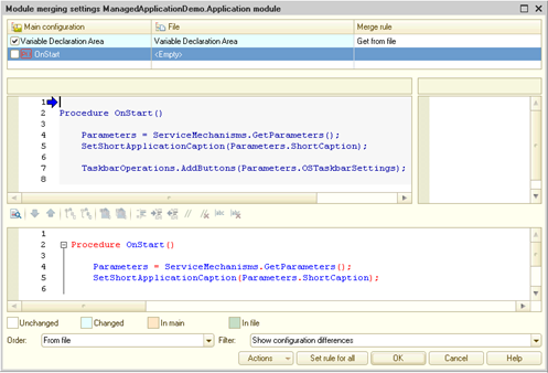
Fig. 689. Opening the content merging setting
After clicking, the merge contents dialog opens.
Fig. 690. Content merging setting
You can customize the information display using the Filter field. The merging setup result for each row in the list can be seen under the list, by placing the cursor on the desired row.
36.10.8. Other objects
For objects with the property values specified in the properties palette (for example, Synonym, Comment), the dependence of the merge results on priority and availability of values is shown in the table below:
| Value in default | Value in loaded | Configuration priority | Result (the value is selected from...) |
|---|---|---|---|
| Specified | Specified | Main configuration priority | Main |
| Specified | Not specified | Main | |
| Not specified | Specified | Loaded | |
| Specified | Specified | Loaded configuration priority | Loaded |
| Specified | Not specified | Main | |
| Not specified | Specified | Loaded |
If an object property can represent the result of a union value of objects of two configurations (for example, the Generated based on property), the result is determined by a simple merge or selected from the loaded configuration.
If the configuration uses several languages and the setting specifies the mode of selective comparison by languages, then comparing and merging such objects is performed considering the languages specified in the language settings.
Templates are merged as follows: the resulting template consists of the templates of the main and loadable configurations separated by a highlighted yellow line. First, the priority configuration template is in the final template, and then another template through the separator. The final merge should be done manually after comparison.
Note. Note. The Template type property is not shown in the Merge configurations window. When merging, this property is merged in the same way as the Template property.
When comparing reference information, two HTML texts are compared not by character, but excluding service tags editor HTML documents.
36.11. Subordinate object order setting
For types of objects that can have an unlimited number of subordinate objects (for example, Attributes, Forms, Templates, Tables and other subordinate objects of catalogs and documents), in some cases the order of objects in every such group is important.
If Designer has mapped objects within a group while merging configurations, but they have different order in the configurations, you can specify the required order in the Merging mode and subordinate object order column.
To specify the order, select any subordinate object and select an ordering option in the third column: Order from main configuration or Order from file.
The selected order is applied to all subordinate objects of this type.
If subordinate objects for the selected object are changed and listed in a different order, you can select only the order in the third column. You can specify the merging mode in the top-level object using the context menu. For example, there are several subordinate objects in both configurations of the Forms type for the Bill document. These forms and their order have been changed. To choose the merging mode, select a higher-level object (Forms or Bill) and choose the required merging mode in the context menu.
36.12. Viewing differences
Before merging configurations, it is useful to review the specific differences of their objects.
For this purpose, you can use the properties palette. Open the properties palette and choose the required object of the main or loaded configuration. You can open forms or templates for viewing. If they are compared with a standard configuration file which is not a distribution file (see Configuration distribution and support), you can make corrections to the loaded configuration data in addition to viewing. If corrections have been made, after the merge is completed, Designer prompts to save all the changes made in the loaded configuration.
To view differences between modules, select Show module differences without structure from the context menu.
Selecting this item opens the Difference between window. If the compared texts are large, it may take several seconds before the window opens. For more details, see Comparing files.
For selective comparison of modules, the Merge modules mode is used (see below).
Select Show template differences from the template context menu to view differences between templates.
This displays the compare window.
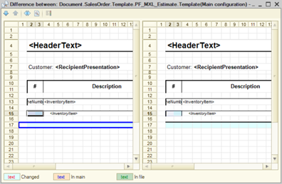
Fig. 691. Merging templates
Spreadsheet documents are compared by cells. In the case of various cells (any properties except the Details parameter), then the difference is shown in color. The color legend is shown at the bottom of the compare window.
The Show help topic differences context menu command must be used to view the differences in the help topics. The window of the following type will be opened in this case:
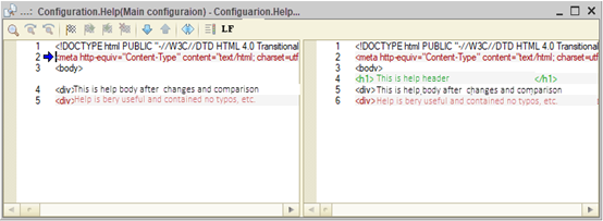
Fig. 692. Comparing help
The dialog opened by the Comparison viewing parameters setting command of the form command panel is intended for setting the colors of comparison results representation.
36.13. Comparing and merging modules
When merging configurations, you can configure the merging process of procedures and functions of any module: application module, common modules, object modules, and form modules.
To do this, in the Merge configuration window, select the line corresponding to the modules being merged, and click the gear icon in the special column. If an external program to perform the module comparing is selected in the Designer settings (see Comparison/merging), it is launched when you click on the gear icon. This external program defines the operations available in this case. You should familiarize yourself with them in the documentation for this external program.
The Module merging settings window is displayed.
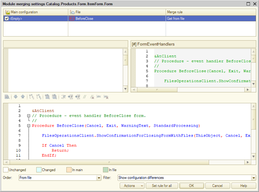
Fig. 693. Module merging setting
The top part of the window contains a table that is similar to the table in the Merge configurations window. The only difference is the fact that the column content is generated from the names of module parts: variable declaration section, procedures and functions section, and initialization section (followed by objects). Any of these sections can be missing. The result of merging under the current rules is displayed in the bottom of the form.
The table field contents corresponds to the set filter (Filter attribute)
In the first column, for objects that are not identical, mark those that you want merged. You can customize the merge settings for the selected objects.
The comparison is performed separately for each section, for mapped objects only. Mapping by name is performed automatically as the initial step.
You can clear any mapping of procedures or functions. To clear mapping, right-click the object row and select Clear object mapping in the context menu.
If in the compared modules you need to compare the objects with changed names, you should perform manual mapping of the objects. To perform manual mapping, right-click any of the objects to be mapped, and then click Map objects.
In fig. 694, you can see that the AddCharacteristics() method has a different content in the main configuration and in the configuration from the file. The result of merging is displayed in the bottom of the form.
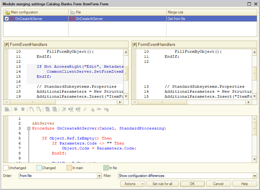
Fig. 694. Merging modules
The text of the selected method, resulting from the merge is shown in the window bottom part. You can edit the resulting text directly while configuring the merge settings. The method text will be loaded into the main configuration, considering the changes made during the configuration process.
When working with the module merge window, to facilitate the work, some auxiliary features are available:
-
The line numbers are displayed for each module (main configuration, configuration from file, and the merge result).
-
If the cursor points to the column with the row number, pressing the left mouse button causes the system to attempt to display the specified row in each of the three modules.
-
Context help is available in the text editor (with the merge result). The context is generated by the main configuration (before merging) and the current (merged) module.
-
Some commonly used commands are available in the text editor command panel with the merge result, such as working with blocks, indent change, setting and removing the comment feature, and so on.
Setting the objects order in the module is determined in accordance with the value of the Order attribute.
To view the result of the module comparison without accounting structure, click the Actions – Show differences in modules without structure. The Differences between window is displayed.
To view the preliminary result of merging the modules, select the Actions – Display merge result.
After the mapping, setting the order and merging mode, click OK to save the module merge settings. Click Cancel to cancel.
After completing the module merging procedure, the Custom settings appears in the Merging mode column and the order of subordinate objects in the Merge configurations window. If you select another mode in the list of merging modes, the customization is lost.
The modules are merged according to the customization performed only for the entire configuration.
36.14. Selecting objects and starting the merging
The list of objects to be merged is generated by checking the box to the left of the icon of a main configuration object. Selecting or clearing checkbox for a top level object sets or clears a mark for all subordinate objects. A check mark indicates that these objects of two configurations will be merged.
The mark of the object takes the Undefined state, if for some of the subordinate objects the mark is set, and for the others it is cleared.
When you open the Merge configuration window, Designer includes all valid objects in the list of merged objects.
When you click the Run button, Designer analyzes the configuration data by the set marks. If no reasons are found to prevent the merging, it proceeds to the merge. The merged configuration is saved automatically.
Upon selective merging of objects that refer to other objects not included in the list of merged objects, Designer displays a list of ambiguous references. An example of an ambiguous reference is the object with the attribute representing a link to another object of the loaded configuration that is not included in the list of merged objects.
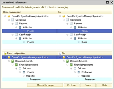
Fig. 695. Ambiguous references
The window contains two table fields. The upper field contains a hierarchical list of all found objects that are linked with the selected objects in the Merge configuration window. The lower field contains a hierarchical list of the objects that use the object specified in the top list.
Use this window to examine links between the selected objects and to decide whether it is necessary to include these objects in the list of merged objects.
Use the Mark all for merge button to select all objects that are necessary for a full merge. When you click this button, the window closes and all required objects in the Merge configuration window are marked.
Pressing the Continue button results in merging of selected objects only, irregardless ambiguous references. In this case, the specialist performing the merge is responsible for the merge result.
36.15. Loading configurations from files
If the entire configuration needs to be replaced while running 1C:Enterprise, you need to load the new configuration from file.
Use the Configuration – Load configuration from file command of the main menu to load changes.
Find and open a new configuration file (1Cv8.cf by default) in the standard file open dialog.
If the current configuration is not empty, the following message is displayed: Configuration is not empty. Loading a modified configuration will replace it. Continue? If you click Yes, it will launch the process of analyzing the differences between the old and the new configuration structures and performing necessary transformations. You will be prompted to update the database configuration.
You can also load a configuration from file to create a new configuration based on the loaded configuration.
Chapter 37. Distributed configuration development
37.1. General information
Configuration development by a team may be carried out sequentially: developers agree on modification of configuration objects, make changes, and then integrate the results. This mode is associated with a risk of accidental changes to various objects. So, it is necessary to understand all modification processes and relationships between objects. In this case, the configuration merging should be performed by a specialist who can effectively steer the direction of development effort.
This chapter explains how to reduce errors probability, increase performance, and simplify the development process through distributed configuration development.
Distributed development environment is simultaneous work of a team of users (developers) on reconfiguration (modification of the configuration), where the object modification can be made only by the developer, which has previously locked the object. In this chapter, the term "configuration" means both the main infobase configuration and any configuration extension connected to the infobase which is being developed (see Configuration extension).
For the distributed development environment, a repository is created, where Designer stores the configuration. Developers are granted access to the configuration repository: either within a local network or using remote access through a web server. An administrator is assigned to the repository, who creates a list of users with an access to the repository. Administrative rights can also be assigned to other users.
In the distributed development environment, the configuration is considered as a set of read-only objects. In order to make changes to an object, the developer has to lock it first. The object can be locked only by one user at a time. The user can lock an arbitrary number of objects not locked by other users.
Techniques for working with locked configuration objects do not differ from those used in the normal mode. The user can edit the properties of the locked object, add and remove subordinate objects.
To add objects, it is required that the object to which they are subordinate be locked. For example, to add a constant, you need to lock the root configuration object. To add an attribute or object form, the object itself has to be locked.
To delete an unlocked object, you should lock the object itself and the object to which it is subordinate, and all its subordinate objects.
After working with locked objects, the result of their modification can be stored in the repository. On the other hand, if any of the unlocked objects have been modified, you can retrieve the updated objects immediately after adding them into the configuration repository by the author of the changes.
Results of working with the repository can be viewed in the repository history. You can open configuration versions stored in the repository to view and compare with the current configuration, database configuration, and various repository versions.
Configuration objects are closely interrelated. So, the configuration repository maintains metadata integrity when objects are locked or stored in the repository.
In this way, the distributed development environment ensures synchronization of configuration modifications by the developer team.
37.2. Repository administration
37.2.1. Creating repositories
Configuration repository is created to share access to configuration objects. To create a repository, select Configuration – Configuration repository – Create repository. The following dialog box opens:
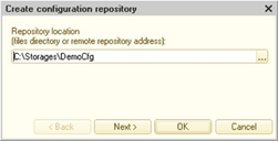
Fig. 696. Creating a configuration repository
Specify the repository location directory in the Repository directory field. No other configuration repository should be registered to the specified directory. Click Next.
The next step is to specify the password policy for this repository: the minimum password length and whether it is required to check the complexity of the password. Click Next.
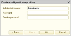
Fig. 697. Assigning repository administrator
Specify the repository administrator name and access password. The Generate password hyperlink will allow you to create a password that satisfies the specified password policy. If a password policy is not specified on the previous page, a 7-character password will be generated. You can also use the password view buttons in the Password and Confirm password fields. The repository administrator creates a list of users who have access to the configuration repository.
After pressing OK, Designer analyzes the data, generates the objects structure, and records the data in the specified directory. This process can take some time (depending on the configuration size). Upon completion of creation of the configuration repository, Designer prompts the user to connect to the repository.
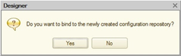
Fig. 698. Connect to repository?
If a configuration repository is registered at the specified address, Designer displays a warning that the repository cannot be created.
When creating a configuration repository, it should be remembered that the repository created for the configuration and the repository created to extend the configuration are incompatible with each other. You cannot connect to the configuration repository for working with the extension and vice versa.
The configuration repository is created in a format version 8.3.8 with a page size of 8,912 bytes. To change the repository database format or page size, use the cnvdbfl utility program. The file of the configuration repository database is named 1cv8ddb.1CD. It should be remembered that Designer version 8.3.7 and higher cannot be connected to the configuration repository created by 1C:Enterprise version 8.3.10 or lower. In this case, it is necessary to perform configuration repository conversion.
37.2.2. Connecting to repository
To connect to the configuration repository, selectConfiguration – Configuration repository – Connect to repository. Before connecting, Designer warns that the current configuration will be replaced by a configuration from the repository and asks for confirmation of the connection.
Upon confirming, the connection dialog box is displayed:
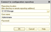
Fig. 699. Connecting to configuration repository
You should enter the location of the repository, username and password to access the repository if they are set. If no one is registered with the specified username, the following warning is displayed: Authentication error! Verify whether the entered username and password are correct. When choosing a repository location, it should be remembered that the configuration repository cannot be used for a configuration extension and vice versa.
For each user, only one configuration can be connected to this repository. Therefore, Designer first verifies the registration of the connection for this user.
If the username was registered and the infobase for this user has not yet been connected to the configuration repository, then the connection is establishing. The configuration from the repository replaces the configuration of the current infobase, and information about the configuration and its location is recorded in the repository for this user.
If there is currently an open configuration associated with the specified user, Designer displays an authentication warning.
If there is no open infobase for this user but the location data does not match the connection data (for example, the configuration is in a different directory or connection is made from another workplace), then Designer displays the following message: Configuration bound to this configuration repository already exists for this user. Continue? Pressing Yes establishes a new connection, and configuration from the repository replaces the current configuration. New connection is established between the current configuration and the repository for this user. In this case, the previous connection will be lost (the infobase that was previously connected to the repository will no longer be able to connect to this user without reconnecting).
After completion of the connection procedure, the configuration window opens.
Not all combinations of compatibility mode of configuration repository and of 1C:Enterprise versions connecting to the repository are compatible:
| Version 8.3.2 and earlier: | Version 8.3.3 – 8.3.5 | |
|---|---|---|
| Version 8.3.5 or higher | Yes | Yes |
| Version 8.3.4 | Yes | Restricted |
| Version 8.3.3 | Yes | Restricted |
| Version 8.3.2 and lower: | Yes |
Compatibility modes are listed in the columns, and the lines indicate the version numbers of Designer that attempts to connect to the configuration repository. The Yes value in the cell means that a certain version of Designer can connect to the repository with the specified compatibility mode. The Restricted value means that only Designers versions 8.3.3 and 8.3.4 can work with the repository without restrictions. If Designer versions 8.3.5 and 8.3.4 simultaneously connect to a repository that is in compatibility mode Version 8.3.3 – 8.3.5, Designer version 8.3.4 cannot store modified objects in the repository.
Also remember that if the configuration repository is created using 1C:Enterprise platform version 8.3.10 or later, then Designer version 8.3.7 or earlier cannot connect to it. If this is necessary, you can convert the configuration repository file to the format version 8.2.14 using the cnvdbfl utility program.
37.2.3. Connecting to repository
If the infobase is already connected to the repository, then parameters to access this repository are requested upon its opening. If after the first connection the parameters did not change, then you need to confirm the connection to the configuration repository. If the location of the configuration repository has changed (without changing the other access parameters), you should specify the new location of the repository in the connection dialog box. Once connected, a configuration window opens.
If, upon connecting to the configuration repository, you specify a username or a password incorrectly or specify the name of a user that is currently being connected to this repository, the following message is displayed: Authentication error! Verify whether the entered username and password are correct.
If you specify another user when connecting to the repository, then the connection will result in the error Existing connection user is different from the current one. In this case (when changing the user, on whose behalf you are working with the repository), you should disconnect from the configuration repository and reconnect with the new user.
If an attempt is made to connect to the configuration repository for the currently open configuration, Designer displays an error message indicating the user name.
If the location of the infobase connected to the repository has changed, a warning will be displayed Location of the infobase has changed. Continue? If the answer is positive, the new location of the infobase is saved in the repository and the connection will be established. If the answer is negative, the connection to the repository will not be established. In this case, to try again to connect to the configuration repository, use the Configure – Configuration repository – Open repository command.
If two infobases are connected to the same configuration repository on behalf of one repository user, then work with configuration repository will be possible only for the developer who has established the connection last. For the first developer, an error will be displayed The infobase is not associated with the configuration repository. In this case, the first developer needs to connect to the repository on behalf of another repository user.
37.2.4. Configuration window
The configuration window connected to the repository is somewhat different from the configuration window not connected to the repository:
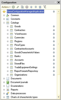
Fig. 700. Configuration connected to the repository
The status of configuration objects is displayed by special icons placed along the right border of the Configuration window. Object and subordinate object icons differ in size (they are smaller for the subordinate objects) and appearance (the subordinate object have an image of a tree branch).
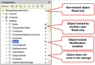
Fig. 701. Objects icons
Possible object states are depicted in fig. 701.
If an object is locked by another user (see fig. 701), then this object can only be modified by the user who locked this object. The metadata object hint that appears above the icon of the object current state in the configuration repository contains the name of the user who locked the object, the date of locking the object by the user, the name of the computer from which the user connected to the configuration repository, and the location of the information base.
Objects created by the user and not yet added to the repository and objects deleted from the repository but still available in the local configuration are indicated by a red mark.
37.2.5. Maintaining a list of repository users
To create a new repository user, select the Configuration – Configuration repository – Repository administration menu item and on the Users tab, select Actions – Add. The window for editing user information is displayed. On the General tab, enter the user name and password to access the repository.
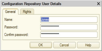
Fig. 702. Repository user parameters
The user rights are specified in the Rights tab.
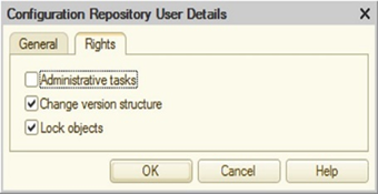
Fig. 703. Repository user rights
Administrative functions. Users have rights to create, delete and disable users, unlock, change the repository compatibility mode and perform optimization procedure.
Changing the version list. Users have the rights to perform a rollback and reduce the version history (see Repository history).
Lock objects. Users have rights to lock and change the repository configuration. If the right is not set, the repository objects are read-only.
37.2.6. Cache versions of the repository
To speed up work with the configuration repository, two cache versions are used. One cache is local. It is located on the side of the computer that is running Designer connected to the repository. The other cache is global. It is located on the computer where the repository directory is located. The cache is designed to speed up some operations on working with the repository. Versions are included in the cache as a result of the following operations:
-
Connecting to the repository.
-
Opening a configuration version in the repository.
-
Comparing configuration versions in the repository.
-
Saving the configuration version in the repository.
-
When the selective comparison is performed of the following configuration objects:
-
Forms (when working through the repository server).
-
Access rights (when working with the configuration repository located on a network resource or through the repository server).
-
Command interfaces (when working with the configuration repository located on a network resource or through the repository server).
-
When it is needed to perform any of the above operations, the system sequentially analyzes the local and global version caches. If the search did not lead to a positive result, the required version is retrieved directly from the repository.
Location and volume of caches are managed using the repository administration dialog box or configuration files.
37.2.7. Configuration repository administration
To administer the configuration repository, use a special window called up by the menu item Main menu – Configuration – Configuration repository – Repository administration.
This will display a window (see fig. 704).
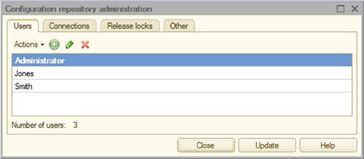
Fig. 704. Repository administration
The Users tab contains the user list configuration developers management controls (hereinafter in this chapter referred to as users). All users can change their own settings (username, password), except for changing rights. Bold font identifies those users who are currently connected to the repository. In fig. 704, the user is Administrator.
The right column of the list displays information about whether the repository user has a password set (picture of a closed lock) or not set (yellow circle with an exclamation mark). Also, under the list, summary information on users is displayed: the total number of users and the number of users without a password. The column and summary information is displayed only to the repository administrator.
Note. WARNING! Adding, deleting, and changing rights are available only to users with administrative rights.
The Connections tab displays the list of users connected to the repository.
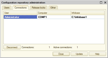
Fig. 705. Connected users
To disconnect any of the specified users that are not currently working with the repository, click Disable.
Note. WARNING! The Disable button is available to users with administrative rights.
On the Unlock tab, objects for the specified user are unlocked.
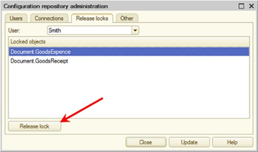
Fig. 706. Unlocking objects
At the same time, the user who locked the objects loses the ability to store changes to these objects in the repository.
Note. WARNING! This button is available to users with administrative rights.
The Other tab contains the settings that control the operation of the repository.
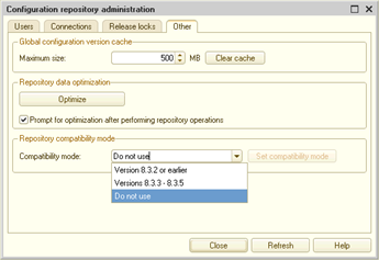
Fig. 707. Repository parameters
The group of the Global cache of configuration versions parameters is used to set the size of the global cache of configuration versions. The cache clearing algorithm is the same as the versions local cache clearing algorithm. The Clear cache button results in a full cache clear.
The group of settings Repository compatibility mode controls the repository format and the way it interacts with the repository server.
The following table shows which system versions can work with the repository with one or another compatibility mode set:
| Compatibility mode | Implemented in version | Can work |
|---|---|---|
| Version 8.3.2 and lower: | 8.3.3 | Any version |
| Version 8.3.3 – 8.3.5 | 8.3.6 | Version 8.3.3 and higher: |
| Do not use | 8.3.6 and later |
If the Compatibility mode property is set to Version 8.3.2 and lower, then any versions of 1C:Enterprise can work with the repository. If this property is set to Version 8.3.3 – 8.3.5 and later (includingDo not use), after you click Install, the repository will be converted to an optimized format. After optimization, working with the repository will be faster (including when using the repository server). Compatibility mode can be changed by a user with administrative rights only.
Note. WARNING! Converting repository might take some time.
If necessary, you can convert the configuration repository back to a format appropriate for use by any versions of 1C:Enterprise. To do this, set the Compatibility Mode property to Version 8.3.2 and lower and press the Install button. In addition, you may need to perform the conversion of the repository file itself. Such an operation may be required if the configuration repository was created in 1C:Enterprise version 8.3.10 and higher. For conversion, you must use the cnvdbfl utility program.
For the new configuration repository, the Compatibility mode property is set to Not to use, and the repository database file is created in the version 8.3.8 format.
With the Password policy group, you can set up the requirements for passwords of repository users. These requirements extend to newly created users and when the password for an already created repository user is changed. If the user is not a repository administrator, this group is displayed but cannot be edited.
The Repository data optimization group allows you to optimize repository that is not in compatibility mode with version 8.3.2. As a result of optimization, the speed of work with the repository will be increased. Optimization should be performed only after the system has prompted to do this.
For a user with administrative rights, a recommendation to perform optimization may be included after an operation with the repository (adding objects, rolling back versions, merging versions). For this purpose, the Suggest optimization after the operations with the repository checkbox is intended on the Other tab of the repository administration dialog box. In this case, after completion of the operation with the repository, the user may be shown the dialog box:
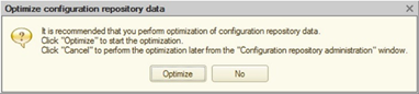
Fig. 708. Suggestion to optimize repository
If the user (repository administrator) refuses to perform optimization immediately after the recommendation appears, then optimization can be performed later. In this case, go to the repository administration dialog box and click the Optimize button on the Others tab. The button should be pressed if the recommendation to perform optimization is displayed to the right of it. Repository optimization might take some time.
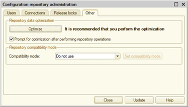
Fig. 709. Optimization is recommended
During the optimization, it is not recommended to work with repository.
Optimization can also be performed using the command line parameter of Designer start /ConfigurationRepositoryOptimizeData.
To configure the local repository data settings, use a dialog box. To access the dialog box, click Main menu – Configuration – Configuration repository – Local repository data usage settings.
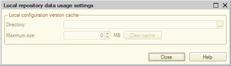
Fig. 710. Local repository data usage setting
Characteristics of the local version cache is specified in this dialog box, and you can also perform optimization of the repository containing the information about development objects.
A local cache is generated when the configuration repository is located on a network drive or is operated using the repository server. The Directory property is used to specify a directory on the local file system where the cache will be located. By default, the cache is located in the directory:
-
On Windows: %APPDATA%/1C/1Cv8/<Infobase UUID>/cfgrepo/cache.
-
On Linux: ~/.1cv8/1C/1cv8/<Infobase UUID>/cfgrepo/cache.
The Maximum size value determines the size of the local cache in megabytes. The default value is 500 Mb. If during operation the local cache size exceeds the set size, the oldest versions of 50% of the cache size will be automatically deleted. TheClear cache button completely clears the local cache.
Thecfgrepo.conf file is used to manage parameters of local version cache.
37.2.8. Repository backup
Depending on the compatibility mode of the repository, the backup is performed differently.
Note. WARNING! During the execution of backup configuration repository, there should be no connection to it.
To perform a backup, you must copy the following files:
-
If the Compatibility mode property is equal to Version 8.3.2 or earlier, copy only the 1Cv8ddb.1CD file.
-
If the Compatibility mode property is not equal to Version 8.3.2 or earlier, copy the 1Cv8ddb.1CD file and the entire data directory located in the same directory as the 1Cv8ddb.1CD file.
37.3. Operating configuration repository
It is convenient to use the Configuration repository window to perform locking, retrieving and adding objects to the repository, as well as other actions with the repository objects. To open it, click Configuration – Configuration repository – Repository.
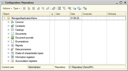
Fig. 711. Configuration repository
The Configuration repository window consists of a toolbar and a table box, the first column of which shows the hierarchical structure of repository objects or a list of objects, depending on the view mode (View menu).
If the display mode for deleted objects is set (View submenu), then the deleted objects are shown in a lighter font in the list.
In the second column, the state of the locked objects is indicated by icons. The icon with a red check mark indicates the objects locked by the current user. The User column specifies the user who locked the object. The Date column shows the lock date (if the object is currently locked) or the date the object was last updated. The name of the user computer is shown in the Computer column, and the name of the local infobase directory on the user computer is shown in the Infobase column.
Note. WARNING! New objects created by the user (not yet stored in the repository) are not displayed in the repository window.
37.3.1. Repository filter
You can customize the objects displaying in the Object column of the Configuration repository window. To call the filter, click Actions – Filter. This opens the following window:
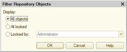
Fig. 712. Filtering repository objects
The names of controls are self-explaining.
It is also possible to quickly filter only those objects that are locked in the repository by the current user.
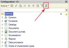
Fig. 713. Filtering locked objects
To do this, click Actions – Locked objects or click a special button on the command bar of the Configuration window. The button is displayed only if the configuration is connected to the configuration repository. The command reexecution disables the filtering. The filtering works in conjunction with the filtering by subsystems (see Subsystems) and search by the configuration tree (see Configuration object tree).
37.3.2. Locking repository objects
Locking a repository object is intended for the editing purpose. The locked object becomes inaccessible for other users (read-only mode and retrieving the modified object for use are available).
To lock an object, select it in the Configuration repository window (you can select multiple objects) and click Actions – Lock in repository...
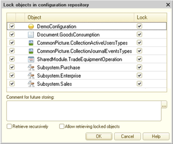
Fig. 714. Locking objects in repository
If the object is linked with other objects, these objects will also be included in the list. In this case, the selected object is shown in bold. Locking the selected object is possible only if these objects are retrieved from the repository.
The list also includes those objects that are not directly linked with the selected object, but are indirectly related.
To retrieve these objects, check the box in the first column of the list. If you also want to lock the objects, select the checkbox in the Lock column. If not all objects required for acquisition are marked for acquisition, Designer displays a message To perform the operation, the following objects are required and lists the required objects. In this case, the locking is not made.
If objects contain subordinate objects which you want to lock, select the Run recursively checkbox.
If you want to retrieve data of the locked objects, select the Allow to retrieve locked checkbox.
Note. WARNING! If the Allow to retrieve locked checkbox is selected, changes made to the locked objects and objects retrieved again will be lost.
After locking, the specified objects will be marked with a special icon.
Upon locking, you can add a comment in advance. This comment can be used when adding an object to the repository (see Storing objects in repository). To do this, add text to the Comment for subsequent posting field or select a comment from the list of previously added comments (button ... in the right part of the field). This list contains the last 20 comments that were added when locking or placing objects.
To add new objects to the configuration, you need to lock the parent object. For example, to create a new directory, lock the root configuration object. To create a new form or directory attribute, lock the directory object.
After locking the parent object, you can create subordinate objects. Then all new and locked parent objects need to be added to the repository.
37.3.3. Storing objects in repository
The modified object can be stored in the repository, so other users are able to update this object in their configurations. To do this, click Actions – Store in repository. The following dialog box opens:
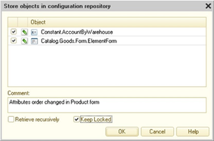
Fig. 715. Storing objects to the repository
You need to select checkboxes for those objects that will be stored in the repository.
To describe the changes made, add them to the Comment multiline text box. If a comment was added when locking an object (objects) in the repository (see Locking repository objects) or was previously used when adding an object into the repository, you can select this comment for reuse from the list of recent comments. To open the list, click the "..." button located to the right of the Comment: field. This list contains the last 20 comments that were added when adding or locking objects.
Fig. 716. List of recent comments
If objects contain subordinate objects which you want to add into the repository, select the Run recursively checkbox.
If you want the specified objects to remain locked, select the Keep locked checkbox.
If objects attached to other configuration objects are added to the repository, a full list of such objects is displayed in the dialog box.
In order to add new objects into the repository, select an object in the Configuration window and select Add into repository... in the context menu. The window for adding objects into the repository is displayed.
In addition to this object, other objects linked with this object may be included in the list. In the list of objects, the selected object is indicated in bold. You cannot add an object into the repository without adding (updating) these objects.
37.3.4. Retrieving objects from repository
To retrieve objects modified by other users, specify the required objects in the list of repository objects and click Actions – Get from repository. The following dialog box opens:
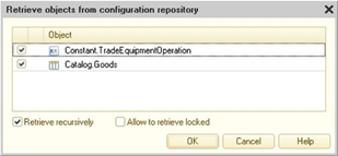
Fig. 717. Retrieving objects from repository
In the rows of the list of objects, you need to check the boxes for those objects that have to be retrieved from the repository.
If the objects contain subordinate objects and you need to retrieve them, select the Retrieve recursively checkbox.
If the selected object is locked already, checking the Retrieve locked box results in the loss of changes made to this object. In this case, the object data is restored with data from the repository.
37.3.5. Unlocking objects
If you do not want to save the changes made to the repository object or you need to provide this object for modification to another user, you can release this object. To do this, click Actions – Unlock in repository.
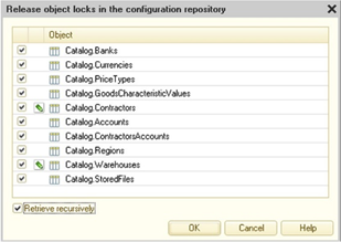
Fig. 718. Unlock objects
In the second column of the list, an icon shows the difference of the object in the configuration and repository. If there is no icon, then the objects do match.
If objects contain subordinate objects and you want to unlock them, select the Run recursively checkbox.
After unlocking, the objects will be retrieved from the repository.
37.3.6. Updating status of repository objects
If you need to update information about objects stored in the repository, run the Update status command. This command updates the information on the locking or unlocking, as well as emergence of new objects throughout the repository.
37.3.7. Comparing repository with current configuration
At any time, you can compare the current configuration with the repository. To do this, click Configuration – Configuration repository – Compare/merge configuration with repository. A comparison window is displayed (see Comparing configurations).
37.3.8. Comparing a repository object with a current configuration object
Sometimes you need to make a comparison of a specific object in the repository and in the current configuration. To do this, in the Repository configuration window, select an object and click Actions – Compare with configuration object.
The following question is displayed: Show configuration comparison results? If the answer is positive, the configurations comparison window is displayed, and configurations are compared. Row with the selected object is activated in the comparison window, and the report settings dialog box is displayed. If the answer is negative, the configuration comparison window is not displayed and no comparison is made.
If compatibility mode with version 8.3.2 is disabled in the repository, you can perform selective comparison of two configuration objects without comparing the whole configuration. In this case, only those objects versions are available for selective comparison that were added in the repository using 1C:Enterprise version 8.2.9 and higher. For selective comparison, use the Perform selective comparison with the repository object, Perform selective comparison with the configuration object, or Perform selective comparison of object versions context menu command depending on where you want to make the comparison: a configuration tree, a repository tree, or a repository history window. When the selective comparison is chosen from the configuration tree, the comparison with the object latest version located in the configuration repository will be performed. If the selective comparison is unavailable, the platform will report this using a diagnostic message.
Selective comparison is available for the following configuration objects: modules, templates, pictures, WS references, schedules, register aggregates, exchange plan contents, styles, home page work area, flowcharts, forms (without form modules), form modules, help, predefined items, command interface sections, and role rights.
37.3.9. Saving repository as configuration
To save the repository as a configuration, click Configuration – Configuration repository – Save repository configuration to file.
37.3.10. Disconnecting from repository
To disconnect from the repository, click Configuration – Configuration repository – Disconnect from repository.
37.3.11. Repository history
The distributed configuration development system maintains a history of configuration objects data changes. The results of adding objects are logged in the history.
You can view each object change and compare it with the current state, compare configuration versions, as well as retrieve a configuration of the specified version from the repository.
To open the repository history window, click Configuration – Repository – Repository history.
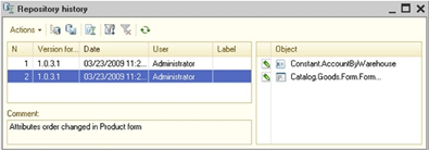
Fig. 719. Repository history
Chronological list of configuration versions is displayed In the table field located in the left part of the window.
Below the list of versions, there is a field to display comments on the selected version.
The list of objects that have been changed, added, or deleted in the selected version appears in the table field located in the right part of the window.
Multiple selections are allowed in the version list. In this case, comments of all selected versions are shown in the Comment field. A list of all objects in these versions is shown in the list of objects.
You can open and view each object from the list in the Repository history window, view change history for this object and compare it with the current configuration object. These actions are performed using the context menu of the list of objects.
37.3.11.1. Working with the repository version
Each version of the configuration repository can be opened for viewing, loaded in place of the current version, compared with the current configuration version or saved to disk. You can also compare the version of the configuration repository with the configuration stored in the file. All the actions are performed using the Actions menu in the Repository history window.
You can use a special report to display information on the repository history. To create the report, in the Repository history window, click Actions – Repository history report. The report settings window will be displayed.
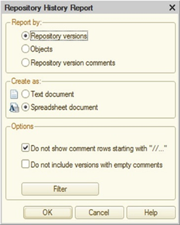
Fig. 720. Repository history report parameters
Select the type of grouping information in the report in the Report by group. In each group, the information is sorted alphabetically.
To group information by version numbers, select By repository versions. To group information by objects, select By development objects. To group information by comments in the repository history, select By repository version comments.
Select the report view type (text or spreadsheet document) in the Show as group.
Additional report settings can be specified in the Options group.
To exclude comment lines starting with "//", select the appropriate checkbox.
To specify objects, for which you want to create a report, and the date range, click the Filter button. In the window that opens, set the filter criteria.
Click OK to start the report generation process.
37.3.11.2. Returning to previous versions
If already published versions in the configuration repository become unnecessary, you can return to the repository version that you need. To do this, in the list of versions, select the one you want to return to and click Actions – Roll back to version. The following warning is displayed: Information about the rolled-back versions will be permanently deleted. Continue? If the answer is positive, a rollback is performed, and all versions stored in the configuration repository after the specified one are deleted.
If a very large number of versions (several thousand) is selected for rollback, then while returning to the previous version a shortage of RAM error may occur and the operation will be interrupted. In this case, it is recommended to perform a rollback operation in smaller portions of several hundred versions.
37.3.11.3. Deleting versions
Should early configuration versions become unnecessary, they can be deleted from the repository. To do this, in the list of versions, select the one up to which you want to delete versions and click Actions – Delete old versions. A warning question is displayed on the screen with a description of the action to perform and a confirmation request. If the answer is positive, all versions stored in the configuration repository before the specified one are deleted.
If a very large number of versions (several thousand) is selected for rollback, then while deleting versions a shortage of RAM error may occur and the operation will be interrupted. In this case, it is recommended to delete versions in smaller portions of several hundred versions.
37.3.11.4. Merging versions
You can merge several consecutive versions of the repository. To do this, select the versions to be merged in the Repository history window (as you select them, a summary statement combining all comments for the selected versions appears in the Comment section, and all objects on which any actions were performed in these versions are displayed in the list of objects) and click Actions – Merge versions. A warning question is displayed on the screen with a description of the action to perform and a confirmation request. If the answer is positive, the versions will be merged, and one version will be generated in the repository history, including the consolidated changes of all versions selected for merging.
37.3.11.5. Tagging versions
Each configuration version can be tagged in the Repository history window. To do this, select the required version and select Change in the context menu. This opens the following dialog box.
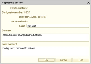
Fig. 721. Repository version
You need to add the tag value. As you enter the first character, the Tag comment field becomes available with the text describing the tag. Tags primarily serve to mark completion of certain logical stages or actions (for example, a new configuration version release, preparation for distribution, and so on).
37.3.11.6. Filter
The dialog box for filtering the Repository history list is different from the standard one.
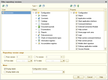
Fig. 722. Filtering versions
Version can be filtered within a time range, range of repository versions (or combination of version and date), by a specified list of repository users who have added versions, by specific configuration objects and by a specific configuration version. You can also set filtering by specific properties of configuration objects. To do this, use the property tree in the filtering settings window. In the example in fig. 722, for all the selected catalogs (AddressShortNames, Banks, PITDeductions in the Object tree), the application will only display versions where manager modules and object modules (in the Property tree) have been changed for these catalogs. To ease selecting properties, there is a button Mark all properties of selected objects in the command panel of the Property tree. This button selects all properties for configuration objects that are marked in the object tree. You can filter history by the following configuration object properties: modules, templates, pictures, WS references, scheduled job schedules, aggregates for turnover accumulation registers, exchange plan contents, styles, home page work area, flowcharts, forms, help, predefined items, command interface sections, and role rights.
When you select the Object item in the property tree, those versions with the changed properties of the corresponding configuration object, for which selective comparison is not available will be logged in history.
You can also specify whether you want to include tagged versions in the filter result and whether you want to show tagged versions only.
For each selected version in the version list, the left side of the Repository history window contains a list of objects that have been added, changed, or deleted. This list is always complete for the given version (does not depend on the filtering conditions). If the specific configuration objects (not the entire configuration) are indicated in the filtering conditions, then the listed objects that satisfy the filtering condition are shown with a different background color.
37.3.11.7. Comparing repository versions
Sometimes you may need to compare configuration repository versions. To do this, in the Repository history window, select two versions to be compared (hold down the Ctrl key) and click Actions – Compare configuration versions or Actions – Perform selective comparison of object versions. For more information on the selective comparison, see Comparing a repository object with a current configuration object.
The specified configuration versions are compared with each other, and the configurations comparison window is displayed.
37.3.12. Object history
To view the history of an object changes in the list of repository objects or in the Configuration window, select the object and click Actions – Object history or Actions – Custom object history. Each object has its own properties set on which you can view the history.
After selecting the type of view, the history filter dialog box is displayed.
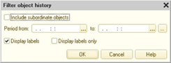
Fig. 723. Filtering object history
You must specify the desired filter parameters and click OK.
The object history window is displayed.
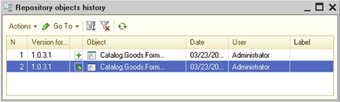
Fig. 724. Object history
Each object change can be viewed and compared with the current state, and the versions can be compared (to do this, select two versions in the list).
You can view comments and tags for each object version similarly to configuration versions (see above), and retrieve the specified configuration version from the repository.
You can filter the object versions list. The filter is applied similarly to the repository history filter described above. In the version filter window, the current object and the respective properties are selected. All properties are selected if you view the whole object history. If you want to view the history selectively, only the specified property is selected.
If you head over to the repository history window, select Repository history from the Go to submenu of the object history window. If you need to open the repository history window and set a filter by the current object, select Repository history by object.
37.3.13. Performing actions with configuration repository without connection
Some actions can be performed without connection.
If the configuration is not connected to a repository, you should establish the connection with the repository first. To do this, select any available item from Configuration – Configuration repository. The connect-to-repository dialog box is displayed.
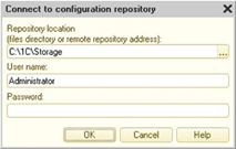
Fig. 725. Connecting to repository
Specify the connection data and click OK.
When you select any of the other available menu items after the connection is established, the connection dialog box is not shown again.
In connected mode, any user actions related to viewing repository data, comparing objects and configurations, as well as full repository administration (for users with administrative rights) are available. Actions related to retrieving objects from the repository are not available.
In connected mode, users with administrative rights can perform any actions related to the repository history.
37.4. Working remotely with configuration repository
37.4.1. General information
Remote work with the configuration repository expands capabilities of distributed configuration development:
-
Configuration repository can be located on a computer running under Windows or Linux.
-
Configuration repository can be accessed by both local network users (over TCP/IP protocol) and Internet users (over HTTP).
For application developers, working remotely with the configuration repository is practically no different from working with the repository located on a shared network resource, except for some features (see Features of remote work with the configuration repository).
Note. Note. Remote work with repository is mainly adapted for high-bandwidth connections. It should be also considered that, when working remotely, the operations with a large data exchange volume, for example, retrieving the full version of the repository, may take significantly longer time.
37.4.2. Architecture overview
37.4.2.1. General information
Remote work with the configuration repository is supported by a special application called configuration repository server. Computer running configuration repository server application (crserver) is also called the configuration repository server. Depending on the access protocol (TCP or HTTP), various patterns may be used for remote communication between the client application and configuration repository. At the same time, concurrent work with configuration repository is supported, both remote and local – as with a shared file resource.
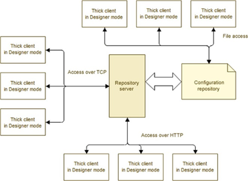
Fig. 726. Remote repository
37.4.2.2. General operational scheme with configuration repository
In general, 1C:Enterprise provides simultaneous operation with the configuration repository using all the repository access protocols: file access, TCP, and HTTP.
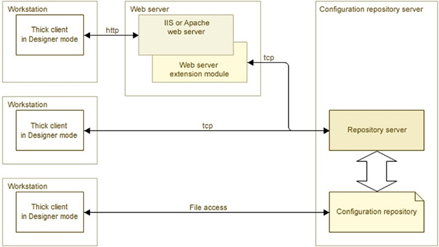
Fig. 727. Interacting with remote repository
Clients can work with different configuration repositories using the same configuration repository server. The only restriction is that all the repositories must be located in the same root directory.
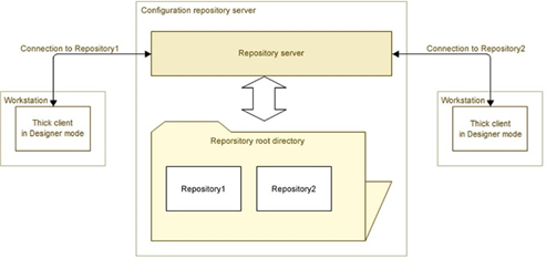
Fig. 728. Location of various repository files
37.4.2.3. Interaction over TCP
When the TCP protocol is used, the client application interacts with the configuration repository server, which in turn interacts directly with the configuration repository itself.
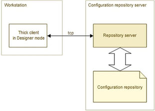
Fig. 729. Interaction over TCP
37.4.2.4. Interaction over HTTP
When HTTP is used, the interaction is executed along the following chain: client application – web server – configuration repository server – configuration repository.
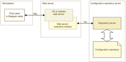
Fig. 730. Interaction over HTTP
37.4.3. Setting up the repository server
After the installation of the configuration repository server, it is necessary to provide the user, on whose behalf the configuration repository server is running with the write and read access to the directory that contains the configuration repository (1Cv8DDB.1CD file and data directory).
37.4.4. Configuring a web server to work with the repository
37.4.4.1. General information
If you plan to work remotely with the repository using the HTTP protocol, then in addition to configuring the configuration repository server, you must configure the web server to work with 1C:Enterprise system and the configuration repository server. Configuration consists of the following actions:
-
Register the web server extension module.
-
Register a virtual application on the web server.
-
Publish the configuration file to work with the repository configuration server.
Note. Note. ISAPI extensions must be supported on the web server.
The publication of the configuration file for working with the configuration repository server comes to placing a file with 1ccr extension in the virtual web server directory. For example, such configuration file can be called repository.1ccr and contain:
<storage
connectString="tcp://RepServ"/>Administrator rights are required to configure a web server.
37.4.4.2. For Microsoft Internet Information Services web server
This section contains settings for the Microsoft Internet Information Services web server (IIS), depending on the version of the web server.
37.4.4.2.1. For IIS versions 5.1, 6.0
You must create a virtual directory. To do this, use the Virtual Directory Wizard from the context menu ofDefault Web Site (Internet Information Services – <Web Server Host Name> – Web Sites – Default Web Site). and then click Create – Virtual directory....
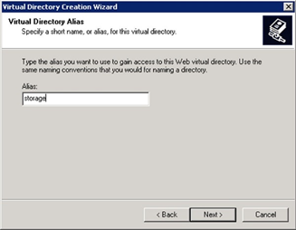
Fig. 731. Setting virtual directory name
The name specified in theAlias field will be used to generate a URL to access the repository. Then you need to specify the path to the folder containing the files of the directory you create.
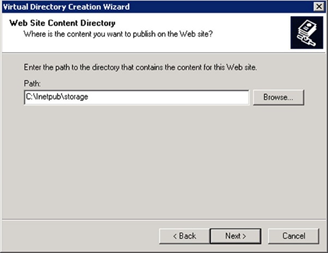
Fig. 732. Specifying directory
As a next step, you need to specify which actions you want to allow when working with the directory. You must specify if there is a possibility to read and run (for example, ISAPI or CGI applications). The rest of the rights should be disabled.
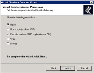
Fig. 733. Setting up permissions
As a next step of the wizard, you must click Finish. This completes the creation of the virtual directory. The next step is to configure the created directory and register the web server extension for it. To do this, open the properties of the created virtual directory and, in the opened dialog box, click Settings.
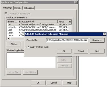
Fig. 734. Registering web server extension
Thewsisapi.dll dynamic library located in the bin directory of the specific version of 1C:Enterprise is an extension of the IIS web server.
Note. Tip. To register a web server extension, use either a short path ("8.3 format") or install "1C:Enterprise" in a directory that does not contain spaces and directory names longer than 8 characters.
An extension (theExtension: field in the dialog box in fig. 734) can be both a specific extension (.1ccr) and a mask of all files (*).
The final step is to restart the web server.
37.4.4.2.2. For IIS 7.0 or later
You need to create a virtual application. To do this, use the Virtual Application Wizard from the context menu of Default Web Site ( – sites – Default WebSite). In the context menu, select Add application ....
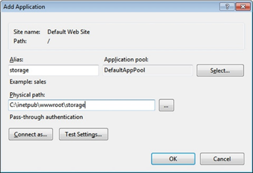
Fig. 735. Creating a virtual application
The name specified in the Alias field will be used to generate a URL to access the repository.
Then add a handler for the .1ccr files. To do this, click <Computer name with web server> – sites – Default Web Site – storage – Handler mappings – Add script mapping….
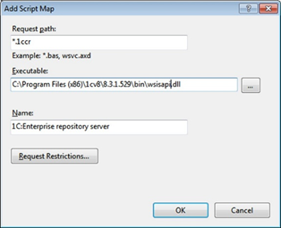
Fig. 736. Adding a handler
The wsisapi.dll dynamic library located in the bin directory of the specific version of 1C:Enterprise is an extension of the IIS web server.
An extension (the Query path: field in the dialog box in fig. 736) can be both a specific extension (.1ccr) and a mask of all files ().
The final step is to restart the web server.
37.4.4.3. For the Apache web server
In order to configure the Apache web server to work with the configuration repository, you must perform the following steps:
-
Enable loading of the web server extension module in the configuration file of the web server (httpd.conf). Depending on the web server version and the operating system, extension modules may have different names:
-
On Windows:
-
On Apache 2.0:wsapch2.dll.
-
On Apache 2.2: wsap22.dll.
-
-
On Linux:
-
On Apache 2.0: wsapch2.so.
-
On Apache 2.2: wsap22.so.
-
-
The web server extension module has the identifier _1cws_module. To load a module, add the following line to the configuration file: LoadModule _1cws_module .
Example on Windows:
LoadModule _1cws_module "C:/Program
Files/1cv8/8.3.1.100/bin/wsap22.dll"Example on Linux:
LoadModule _1cws_module
/opt/1C/v8.2/i386/wsap22.so- Create a virtual directory on the web server through which the configuration repository will be accessed and register a file handler for the virtual application directory. ID of the handler to be registered: 1c-application.
Example of a virtual directory for Windows OS:
Alias "/repos"
"C:/www/repos/"
<Directory "C:/www/repos/">
AllowOverride None
Options None
Order
allow,deny
Allow from all
SetHandler
1c-application
</Directory>Example of a virtual directory for Linux OS:
Alias
"/repos" "/var/1C/www/repos"
<Directory
"/var/1C/www/repos">
AllowOverride None
Options None
Order allow,deny
Allow from all
SetHandler 1c-application
</Directory>- Add the *.1ccr file to the folder with the virtual directory files. In the file, specify the configuration repository server address in the TCP scheme.
Example of .1ccr file:
<?xml
version="1.0" encoding="UTF-8"?>
<repository
connectString="tcp://192.168.0.12"/>- Restart the web server.
37.4.4.4. Configuring a web server for several versions of the configuration repository
You can use configuration repositories that are serviced by different versions of the 1C:Enterprise system. For this, perform the following steps:
-
Create a new instance of the configuration repository server that runs on a port with a unique number. The port must be unique for the computer where the repository server is running.
-
Each repository server must be published in its own virtual application (including a correctly generated 1ccr file).
For web servers, simultaneous operation with different 1C:Enterprise system versions requires specific settings:
-
For IIS Web Server: It is required to create an application pool for each unique version of the repository server.
-
For Apache web server: It is required to create a web server instance for each unique version of the repository server.
The "unique version" means the full 1C:Enterprise version number (4 values separated by "."). To find out how to create a new application pool or a web server instance, see the web server documentation.
Further configuration of web servers is no different from when you publish the default configuration repository. For the IIS web server, configure the application pool with the required version of the repository server. For the Apache web server, configure the web server instance with the required version of the configuration repository server.
37.4.5. Start the repository server
With Windows operating system, the configuration repository server can be started as an application or installed as a service.
With Linux operating system, the configuration repository server can be started as a process or as a daemon.
37.4.5.1. On Windows
The repository server is started from the command line:
crserver.exe -instsrvc
| -rmsrvc -usr <user> -pwd <password>
-start | -stop
-port <port> -d <directory>If you install the repository server as a service, it is named 1C:Enterprise 8 Configuration Repository Server.
Note. WARNING! The command name and value must be space-separated.
| Command | Description |
|---|---|
| -d | The root directory for configuration repositories. The default directory is %LOCALAPPDATA%/1C/1Cv8/. |
| -instsrvc | Register the repository server as a service. |
| -port | The working port of the repository server. The default port is 1542. |
| -pwd | Password of the user on whose behalf the service is registered. |
| -rmsrvc | Unregistering the repository server as a service. |
| -start | Start the repository server service. |
| -stop | Stop the repository server service. |
| -usr | Name of the user on whose behalf the service is registered. This user must have the Log on as a service right. In addition, they must have permissions to read the executable file directory of the corresponding 1C:Enterprise version and full rights to the root directory of the configuration repository (the %LOCALAPPDATA%/1C/1Cv8/ directory or the directory specified in the d parameter). |
37.4.5.2. On Linux
The repository server is started from the command line:
./crserver
-daemon -port <port> -d <directory>Note. WARNING! The command name and value must be space-separated.
| Command | Description |
|---|---|
| -d | The root directory for configuration repositories. The default directory is /home/usr1cv8/.1cv8 or ~/.1cv8. When working with the repository server, an error <FullFileName> too many open files may occur. In this case, you need to increase the maximum number of opened files for the process using the /etc/security/limits.conf file (you need root privileges (root)). For the user, on behalf of which the repository server is started, change the value of the nofile parameter. The value is chosen empirically and depends on the size of the configuration and the number of users working with the repository. It is recommended to use 100,000 as the initial value. If the error persists, then the value of the parameter nofile should be increased. |
| -daemon | Start the server as a daemon. |
| -port | The working port of the repository server. The default port is 1542. |
37.4.6. Connecting to the configuration repository server
Connecting a client to the configuration repository when working remotely is performed in the same way as when working with repository located on a shared network resource. The only difference is in the way of specifying the repository catalog. Depending on the protocol used, the repository directory can be specified in two ways.
For TCP protocol:
tcp: //<repository
server name>/<relative repository path>For HTTP protocol:
<description file
address>/<relative repository path>Example:
tcp://RepServ/MyConfRepOr:
[http://www](http://www).MyCompany.ru/VirtualFolder/storage.1ccr/MyConfRep-
RepServ. Name of the configuration repository server.
-
http://www.MyCompany.ru. Address of the web server where the Web service description file is published.
-
http://www.MyCompany.ru/VirtualFolder/storage.1ccr. For full address of the description file, see the HTTP scheme.
-
MyConfRep. Relative path to the configuration repository.
The relative path is specified from the default directory (%APPDATA%/1C/1Cv8/) if the directory was not specified explicitly, or from the directory specified in the d parameter when starting the repository server. If the relative path to the repository is not specified, a connection to the default repository will be made (maincr directory).
When working with the configuration repository server, the repository server and Designer versions should match. In case of a mismatch between Designer and configuration repository server versions, the work with repository is impossible.
37.4.7. Creating a configuration repository
When you first start the configuration repository server, a default directory will be created on your computer to host the configuration repository. This directory is named maincr. If the d key was not specified when starting the server, the configuration repository will be located in the %APPDATA%/1C/1Cv8/maincr directory by default.
To create a new configuration repository, you need to create the repository from the client application in Designer mode, specifying the required new directory as the repository directory.
To ensure maximum performance, it is recommended to place the configuration repository root directory on the configuration repository server computer. 1C:Enterprise supports the placement of repository directories on network resources available to the repository server, but this option may result in reduced performance.
37.4.8. Features of remote work with the configuration repository
When working remotely with the configuration repository, the status of objects in the repository does not update automatically. To update information about the objects placed in the repository, click Actions – Update statuses.
Active users working with the configuration repository remotely are not highlighted in bold in the list of repository users.
37.5. Recommendations for using repository
To provide a group of developers with information on the changes made, each developer together with the placement of modified configuration objects in the repository compiles a description of the changes made.
To describe the changes, you need to generate a text report comparing the working configuration with the repository configuration (only for configuration objects placed in the repository) and place it in an accessible location.
The administrator of the repository from time to time (period is determined by the work intensity) should backup the repository and reports on changes made by the developers.
It is not recommended to perform group operations with the repository (retrieving objects, placing objects, and so on) and disable configuration support with the configuration comparison window open.
Chapter 38. Configuration distribution and support
38.1. General information
Standard configurations are changed regularly. This may be due to changes in legislation, introduction of new features, or adjustments. So, the support mechanism for these configurations is of great importance for users of typical configurations.
"Distribution", "Configuration support", and "Distribution package" are used to describe the support mechanisms.
Distribution. There are a complete distribution and distribution of updates. Complete distribution represents a configuration file of .cf format, specifically generated. Distribution of updates is an update file of .cfu format.
Support. Configuration support makes it possible to update the configuration using Designer mode and distribution files. The purpose of the support mechanism is to protect the logical integrity of the configuration. The description also uses the "Supported configuration" term.
Distribution kit is a distribution package, which includes the installer for Windows (setup.exe file). Linux (setup file), and macOS (setup.app directory, which represents an installer for operating systems) as well as distribution files compressed in a special archive (1cv8.efd file). The language of the distribution package corresponds to Designer language. Localized distribution resources are located in the distribution directory, in a subdirectory with the name corresponding to the language name.
Designer allows developers of typical configurations to distribute not only new configuration versions, but also to set the support mode for these configurations considering the changes made in user configurations.
38.2. Configuration distribution
38.2.1. Distribution settings
Configuring the distribution is to specify vendor rules for modifying configuration objects by developers supporting end-user configurations.
To set rights, select Configuration – Configuration – Distribution – Distribution settings. The distribution setup dialog box appears.
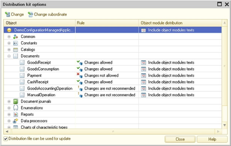
Fig. 737. Distribution settings
In the hierarchical list of configuration objects, the first-level objects are available only.
For each object you should specify the rule of change. To do this, specify the object and click Edit. To change the rules for an object group, select the group and click Edit subordinates.
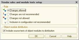
Fig. 738. Vendor rule settings
Multiple selections are allowed in the object tree. In this case, selected objects are configured.
You can specify the following rules:
-
Changes allowed. Any change in the user configuration is allowed.
-
Changes not recommended. Changes in the user configuration are not recommended.
-
Changes prohibited. Changes are completely prohibited. This right does not authorize to modify supported objects. Support cannot be disabled for an object with such a rule. To modify such an object, you need to disable support for the entire configuration.
-
Inclusion in configuration is not recommended. When enabling support by combining with the vendor configuration or when updating a new version of the vendor configuration, an object with such a default rule is not offered for inclusion in the user configuration.
By default, Designer sets the Changes allowed rule.
If only compiled module text is included in the distribution, you need to clear the Include the source code for object modules in distribution checkbox. In this case, the functionality is not broken, but the module text is not available for viewing. Source texts removal is not supported for the following modules:
-
Managed application module
-
Form modules
-
Command modules
-
Modules including preprocessor directives
-
Client general modules operating in a managed mode (thin client, web client, and a managed mode of thick client)
Note. Note. If Include the source code for object modules in distribution checkbox is cleared for the root element configuration, then the regular application, external connection, and session modules will be distributed without source texts.
To customize the distribution file, select the Distribution file can be used for updating checkbox if the distribution file is intended for standard configuration updating. Clear the checkbox when the received distribution file will be used as an intermediate when it is required to make a series of successive updates.
For example, changing the type of attribute with conventional technology can lead to a loss of user-entered data. So, an intermediate version is often used with a new attribute of the required type, while the former attribute remains there. Normally, only the update file is prepared. Special data processor performs data conversion. Then, the next configuration version is used, where the name of the auxiliary attribute of the desired type is replaced with the previous one. The purpose of the second version is the execution of the transition function only, so it cannot be used as a separate update.
After specifying the rights, click Close.
38.2.2. Creating distribution files
To create distribution and update files, select Configuration – Configuration distribution – Create distribution files and configuration updates.
Preliminary, in the Development property category, the Vendor and Version properties should be specified.
Vendor. Configuration vendor name.
Version. Configuration version (line).
Note. Tip. The recommended version number format is <version>. <subversion>. <release>. <build> where each element is a decimal number. This structure simplifies the identification of configuration version during the sequential development and construction of the distribution files (packages).
In the list of templates and configuration updates, configurations are sorted by version numbers taking into account the number structure.
If the configuration or database are modified, Designer requests to save the configuration and update the database configuration.
This will display the distribution generating window.
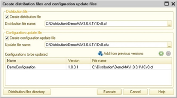
Fig. 739. Generating a distribution package
By clicking File distribution directory, a directory is created that will be used to create new versions of distribution directories. The version directory name is the same as the version number.
To create the distribution file, select the Create distribution file checkbox. In the name field, the default name of the distribution file will be suggested.
To create an update file, select the Create configuration update file checkbox. In the name field, the default name of the distribution file will be suggested.
If the Create configuration update file checkbox is selected, include previous updates in the update file. To do this, run the Add from previous versions command and select distribution files of previous versions.
To generate the specified files, click Run.
The distribution package text files must be prepared in UTF-8 encoding.
Obtained files are passed to developers supporting end-user configurations.
38.2.3. Preparing the distribution package of replicable configurations
To create a distribution package, you must first create a description of the package (stored in a file), and then create a distribution package in accordance with this description.
38.2.3.1. Distribution package description
To create the description of the distribution package, select Configuration – Configuration distribution – Distribution package.
The following dialog box opens:
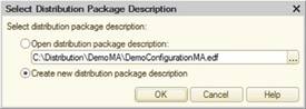
Fig. 740. Selecting a distribution package description
In the dialog box, select the mode description.
Use the radio button to Open package description if you want to modify the existing description. Description file is specified in the input field.
To create a new description, set the Generate a new description radio button.
38.2.3.1.1. Creating a new distribution package description
The window of distribution package creation assistant is displayed.
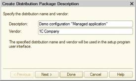
Fig. 741. Distribution package creation assistant
Specify the name of the distribution package and the vendor. Click Next.
In the next step, specify the template parameters.
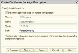
Fig. 742. Creating distribution package description
By default (the Define settings by current configuration checkbox is selected), settings are selected from the corresponding configuration properties. You can modify these settings if the checkbox is cleared.
The Path parameter specifies the directory where the manifest file will be created.
Template parameters are written to the manifest file that is included in the distribution package.
In the next step, specify the template parameters.
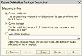
Fig. 743. Setting templates parameters
Specify the template files that should be included in the description of the distribution package. Specify the directory for additional files included in the package. All files in this directory, including subdirectories, will be included in the distribution package description.
To create a description, click Finish. Editing window for the distribution package description is displayed.
38.2.3.1.2. Editing distribution package description
Editing window for the distribution package description opens after creating the description (see the section above) or when choosing the editing mode (see Distribution package description).
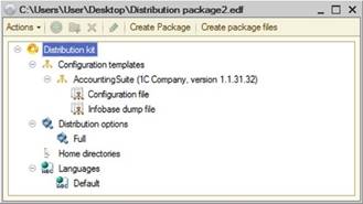
Fig. 744. Distribution package description editor
Use the package description edit window to specify distribution package creation settings.
Description is a tree with four main branches:
-
Configuration templates
-
Distribution package options
-
Home directories
-
Languages
You can add new data, delete unnecessary, and modify existing properties for any branch. Use the Action menu to manage the distribution package description. To edit properties, use the property palette.
Configuration templates
Configuration templates are the main items of the distribution package. The Configuration templates include files and groups of files.They can include files of any type or file sets that match specific masks. They can also include configuration files or dump files created from the current infobase.
Each template is stored in the template directory. Files and file groups are stored in the template directory, their locations based on the manifest file address (file groups are stored as subdirectories).
Only configuration and dump files are included in the manifest file. Other files are located in the configuration template directory.
Templates
To set up the template properties, select a template and specify its properties.Current configuration. If the checkbox is selected, use the current infobase data (Vendor, Name, and Version). If the checkbox is cleared, you can edit these properties:
-
Vendor. The configuration vendor (corresponds to the Vendor configuration property).
-
Name. The configuration name (corresponds to the Name configuration property).
-
Version. The configuration version (corresponds to the Version configuration property).
-
Location of manifest. A relative path to the template manifest file in the template directory.
Files and file groups
To add a file, select a template and click Actions – Add. This opens the file selection dialog box.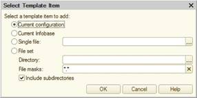
Fig. 745. Adding file to a template
Specify the location of the template item to add to the dialog box.
The file can be located in the current configuration, the current infobase, in a separate file, and represent a set of files of the specified directory selected by the file mask (files of subdirectories can be included).
To configure file properties, select a file and specify its properties:
-
Description. The file name.
-
Data. The file data source (a file, current configuration, or current infobase).
-
Home directory. The home directory for the file reference.
-
File/Directory. The path to the file, absolute or relative to the home directory.
-
Place on support. Enable support for a configuration or dump file.
-
Include in manifest. Include the configuration or dump file in the manifest.
-
Name in template. The name in the template directory. The name is subject to localization to the distribution package languages.
-
Location. The default infobase directory.
-
Name for updates. Use the file name in the template directory to name updates.
To add a group of files, select a template and click Actions – New Group. In the property palette, enter the group name.
If you specify a group in the list and select Actions – Add, a file is added to this group. The number of files in the group is unlimited.
Nested groups are allowed.
Distribution package options
Distribution options are various combinations of distribution package files. Such combinations can be used for different distribution sets. For example, the full distribution package or updates only.
-
Description. The name of the distribution package option.
-
Distribution files. A set of distributed files. By default, the full distribution option that includes all files is created. If the number of options is specified, in the property palette, click Edit to generate the file set. It is necessary to check files that will be included in the selected option.
-
Distribution description file. The description displayed to the user after the product installation.
-
Home directory and Directory. The location of the distribution package and the distribution files. If these directories are specified, they will be filled automatically in the query dialog box.
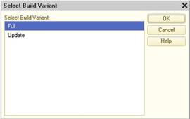
Fig. 746. Construction option
Home directories
Home directories are used to specify distribution file locations that do not depend on a computer.
An environment variable or a directory name can be specified as a home directory. Then the distribution package file name can be specified as a combination of the home directory and the relative path from this directory.
-
Description. A home directory name.
-
Base. This parameter can take two values:
-
Environment variable,
-
Directory.
-
-
Environment variable/Directory. Contains an environment variable name or the absolute address of the directory depending on the Base value.
Languages
Add the languages for localizing template item names.
To have the names displayed correctly, language names must correspond to 1C:Enterprise directory names containing the localized interfaces. One of the languages is the default language. If there is no line in the current platform language available, the line in the default language is used instead:
-
Description. The language name.
-
Resource directory. The current language resources directory name.
38.2.3.2. Creating distribution packages
To create a distribution package, click Actions – Create package archive. This creates a zip-archive of a distribution package for the selected distribution option. The archive will contain 1cv8.efd file (containing configuration files, configuration updates, dump files), support files of the distribution package and files that are used to install the application on each of the supported operating systems:
-
Windows: setup.exe file.
-
Linux: the setup file.
-
macOS: setup.app directory with all the files required for installation. The operating system treats the directory as an installer.
For Linux and macOS executable files, the correct attributes of the executable files are set. So, when unpacking the generated archive on the target operating system, you can immediately run the application installation. However, if you unpack the archive on Windows OS and then copy the files to a disk drive that will be used on Linux OS or macOS, then the attributes of the executable files will be lost.
To create distribution package files, select Actions – Create distribution package files. This creates unpacked distribution files without a setup program based on the selected distribution option.
If the package description has not been saved yet, Designer prompts you to save it.
If more than one option is specified, the option selection dialog box is opened. In the dialog box, select the desired option.
Place update package files in the resource directory specified in the Update directory address property (see Updating configuration).
In addition to licensing with the use of a hardware key that limits the total number of workplaces and does not control the used configurations, it is allowed to use electronic licenses that are issued for a specific workplace and control the use of certain configurations on it that are recorded in the license. Software licenses are issued by 1C Licensing Center and stored on the user's computer.
Note. Note. To create a distribution package configuration distributed under the licensing of the user workplace, the -DigiSign parameter is used for Designer batch run /CreateDistributionFiles and / CreateDistributivePackage. It allows you to specify a file with licensing parameters. The partner may create and distribute configurations supporting the licensing of the user workplace under a separate agreement with 1C company.
38.3. Configuration support
38.3.1. General information
A new version of the configuration can be obtained as a distribution file (new version of configuration distribution file) and / or as an update.
User configurations that can be updated with the received distribution files must be supported.
The object support mode can be changed, having previously disabled full support. The capability of setting user rules (for objects modification) depends on the rules stipulated by vendor and on current locks in the user configuration.
The following features are available for a supported configuration: comparison with distribution, comparison of a new distribution with an earlier one and comparison of the current configuration status with the original one.
If the configuration is supported, objects in the Configuration window are marked with special icons located to the right of the object, along the window border.
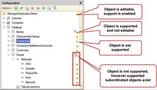
Fig. 747. Support modes icons
Descriptions of icons for various support modes are given on fig. 747.
38.3.2. Setting up configuration support
When a standard configuration is installed, configuration support is automatically enabled.
If the configuration is not supported, use the Configuration – Compare and merge with configuration from file command to enable support and select the distribution file as a file for comparison.
In this case, Designer offers to enable the configuration support. Dialog box with the Possible merge option with enabling support is detected message appears and reports the basic parameters of the vendor configuration. Query for support setup is displayed.
Clicking Yes opens the configuration compare and merge window.
After specifying the merge conditions and modes, click Run. Configurations are analyzed object-by-object to determine compliance of the vendor rules with the merge rules.
If the vendor rules for any objects conflict with the merge rules, a list of these objects is displayed in a separate window. Adjust the settings in the compare window to eliminate all conflicts and repeat the merging attempt. If there are no rule conflicts, configurations are merged and support is enabled for the current configuration.
When setting up support and updating the vendor configuration with the option of changing the vendor configuration enabled, the detailed configuration of default support rules can be performed for objects with different distribution rules.
If the current configuration is connected to the configuration repository, it is required that all configuration objects, which should be taken from the vendor configuration, and the root configuration object are locked in the repository when a configuration is set for support.
38.3.3. Support setting
Configuring support settings represents the setting of user rules for each configuration object.
For support setting, select Configuration – Support – Support setting. The support rules configuration window is displayed.
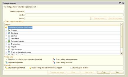
Fig. 748. Support setting
In the top line of the configuration window, Designer reports on the current support status of this configuration.
The configuration name, vendor, and current configuration version are specified below.
The Object support rules settings section contains the object tree, vendor support rules, and user rules for each object.
The vendor support rules cannot be changed. Only user rules can be changed (provided that full support for the configuration has been disabled). You can make multiple selections in the configuration window to configure the same support rules for selected objects. Use the context menu in the support rule columns to change the support rules.
Distribution package may contain data in several languages. Use the support language selection feature to specify the languages that are used in the current configuration. Click Support languages to open the language selection window and specify the languages.
Fig. 749. Selecting configuration support languages
38.3.3.1. Full (automatic) support
If the status bar of the support configuration window displays Configuration is supported, it means that all objects of this configuration are supported and cannot be changed (edited). In this case, the configuration can be updated automatically.
To update the current configuration automatically:
-
Select Configuration – Support – Update configuration.
-
Select a support file.
The update is performed without displaying the Compare and merge window.
Changing user rules for any configuration object is not available in this state, regardless of the vendor support rules.
38.3.3.2. Support with updates
It is often necessary to modify the standard configuration to meet the specific user requirements. In such cases, support of some objects has to be disabled fully (the vendor object is not supported) or partially (the vendor object is editable with the capability of support).
To be able to change user support rules, click Enable modification in the support setup window.
After clicking the button, the following warning is displayed: Changing the mode results in inability to perform a configuration update automatically. Continue? If you click Yes, you are prompted to select support rules for objects with different distribution rules.
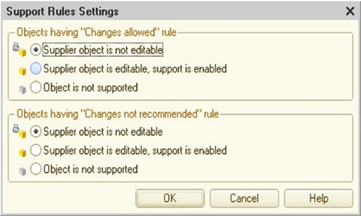
Fig. 750. Support rules settings
After specifying the support rules and clicking OK, the configuration status is changed, and the configuration is supported with the possibility of change. As a result of this setup, all configuration objects will be blocked from accidental changes, regardless of the distribution rules set by the vendor. To make changes to an object, it is necessary to explicitly include the option to change the object or its subordinate objects (see Changing support rules for objects).
If you do not need to change the support mode (actions were wrongly performed), close the configuration without saving.
After the full support is disabled, reinstalling support for the entire configuration is possible only by performing the following actions in sequence:
-
Disable support for the configuration (in the settings window, specify the root configuration object and click Disable support).
-
Select Configuration – Load configuration from file.
-
Select the distribution file.
38.3.3.2.1. Changing support rules for objects
To change the support rules, in the object tree of the support settings window, select the desired object and select Install support rule in the context menu. In the dialog box, select the desired user rule from the three possible:
-
Vendor object is not editable.
-
Vendor object is editable, support is enabled.
-
Support for the vendor object is disabled.
The vendor support rule determines the availability of rules.
If the Changes allowed vendor support rule is set, then the setting of any vendor rule is available.
If the Changes are not recommended provider support rule is set, then installation of any provider rule is also available, but if this rule changes, a warning message will be displayed.
If the Changes disabled vendor support rule is set, the vendor rules can not be installed.
Note. WARNING! After the Support is disabled for the vendor object user rule is set, you cannot bring back the rule Vendor object is not editable.
If the selected object contains subordinate objects, then to change the support rules simultaneously for these objects, select the Install for subordinate objects checkbox (set by default).
Disable support completely. To disable support for all configuration objects, select the Actions – Disable support. The warning is displayed: Disabling support will make it impossible to get updates from the vendor. Continue? To disable support, click Yes. Support for the configuration is completely disabled. If these actions are wrong, close the configuration without saving.
Note. WARNING! Disabling support does not mean that this configuration cannot be updated using the compare and merge method.
38.3.3.2.2. Comparing and merging with the vendor configuration
From the support configuration window, you can make comparing and merging with the original (previous) distribution file. To do this, click Compare, merge. This opens the compare and merge window.
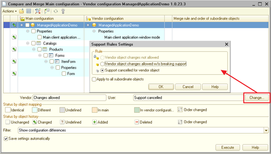
Fig. 751. Comparing and merging with the vendor configuration
For the main comparison and merging methods, see Comparing and merging configurations.
Unlike the standard mode of comparing and merging configurations, a line showing the vendor and user rules has been added to the compare window and the Edit button to change the user rule. In the opened dialog box, you can specify a support rule, indicating it also hierarchically (the Set for subordinate objects checkbox).
When compared with the distribution file, the current configuration is always a descendant of the vendor configuration. So, there is no button to select the configuration settings mode.
38.3.4. Updating configuration
To update supported configuration, select Configuration – Support – Update configuration.
This opens the update assistant.
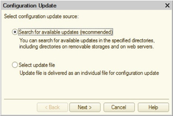
Fig. 752. Update assistant
In the first step, the user can select a separate update file for a configuration update or start searching for possible update files locations.
If a separate update file is selected, this file is selected in the next step.
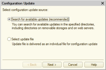
Fig. 753. Selecting an update file
Clicking Finish opens a dialog box with the basic parameters of the current configuration and the vendor configuration (see below).
If the search for individual updates is selected, then after clicking Next>, the update wizard proceeds to selection of possible update locations.
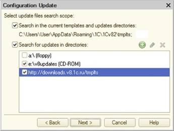
Fig. 754. Update locations
Possible locations are:
-
Current template directory.
-
Removable drives. The v8updates directory is added for CR-ROM drives.
-
Address specified in the configuration as the update directory address.
Searching for updates on the specified directories is performed as follows:
-
For local directories, searching for update files and template list files is performed in specified directories and subdirectories. The template list files found should describe template directories and be in the root of these directories.
-
For remote directories, the template list files are searched only in the specified directories.
If the Update catalog address configuration property specifies a configuration update address, then clicking Next> performs user authentication.
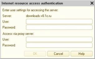
Fig. 755. Internet resource access authentication
Enter the user name and password to gain access to the server hosting the update kit, as well as the name and password to access via the proxy server.
In the third step, the updates are shown, for which the corresponding templates have been found. In the list of these updates, an update that is most likely suitable for the configuration update is shown in bold.
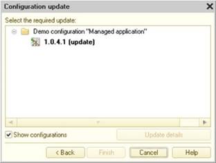
Fig. 756. Selecting an update
If an update located in a remote directory is selected, this update is copied to the current (local) template directory.
Clicking Finish completes the search for an update file.
A dialog box is displayed with the basic parameters of the current configuration and the vendor configuration.
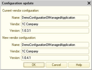
Fig. 757. Update options
A warning should be noted in the bottom of the dialog box to acknowledge that the source of the configuration update file is reliable and does contain an update of the configuration used, without any unwanted modifications (see Unsafe action protection).
To continue, click OK.
Designer compares configurations and opens the Configuration update window.
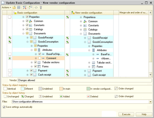
Fig. 758. Updating configuration
For the main comparison and merging methods, see Comparing and merging configurations.
If the use of an external program (see Comparison/merging) is selected in Designer settings, then for program modules the Merge using external program item is added to the list of merge modes. When this mode is selected, the external program capabilities are used to merge modules. If the Automatic three-way merge property is not populated for the selected external program, then interactive three-way merge is used. An interactive three-way merge is also used if the external program could not automatically resolve conflicts when merging is performed.
Some actions that can be performed in the configuration update window depend on Designer settings (seeComparison/merging):
-
TheShow differences in modules context menu command:
-
Designer settings: "Retrieve from ...", "Merge with priority ..." modes
-
External program settings: Merging two files
-
The result is ignored.
-
-
The Show differences in modules irregardless the structure context menu command:
-
Designer settings: Show differences without structure
-
External program settings: Comparing two files
-
The result is ignored.
-
-
Actions performed when the merge mode is specified Retrieve from ... or Merge with priority ...:
-
Designer settings: "Retrieve from ...", "Merge with priority ..." modes
-
External program settings: Trilateral merging
-
The result is used as the merge result.
-
-
When specifying the merge mode Merge using external program, the following actions are performed:
-
Designer settings: "Merge using external program" mode
-
External program settings: Trilateral merging
-
The result is used as the merge result.
-
-
Actions performed after clicking Run:
-
Designer settings: Supported configuration update group
-
External program settings: Automatic trilateral merging or Trilateral merging
-
The result is used as the merge result.
-
When calling a command, the tool specified in the corresponding Designer settings will be used, and if any external program is selected as a tool, the command line specified in the corresponding external program settings will be used to perform the action.
When merging configurations, the modules are merged first. For the Merge using external program mode, launching an external program that supports automatic three-way merge is performed only when conflicts are detected. If the developer did not save the merge result, the module text does not change, and the configuration merge continues. If among all the modules there was at least one unresolved conflict, then after an unsuccessful attempt to merge the modules, the configurations merging stops, and a list of modules that have not been merged appears in the message window. The merge configuration window does not close. The column in the object tree that indicates the merge setup status is updated. The developer should manually merge the non-merged modules and continue to merge configurations by clicking Run.
The following merge rules are used to merge the values of type Type:
-
The Retrieve from file merging mode:
- The type description is replaced with the value from the new provider configuration.
-
The Merge with priority merging mode:
-
To simplify the description of merging values of the Type type, it is assumed that any type is considered a union type, regardless of whether it actually is or can be a part of one.
-
When merging, the following operation is performed for each element of the types being merged:
-
If there is a type available in the old vendor configuration and not provided in the new vendor configuration or in the main configuration, it is not included in the merge results.
-
If there is a type available in the new vendor configuration or in the main configuration and not provided in the old vendor configuration, it is included in the merge results. If the type is available both in the new vendor configuration and in the main configuration, and this type has qualifiers, then the merge rules for qualifiers are used (see Data types).
-
The type is present in all three configurations:
-
At the same time, if the type qualifiers for the object of the old vendor configuration coincide with this type qualifiers in one of the remaining configurations, and the qualifier in the other configuration is different, the merge result includes a different type value (the merge priority is not considered in this case).
-
And while qualifiers differ in all three configurations, the qualifiers from the priority configuration are included in the merge result.
-
For the same types with different qualifiers, use rules for qualifiers described below. That is, if there was a Line(10) in the database, the vendor keep it the same, and in the main configuration it is changed to Line(15), the result is Line(15), regardless of priority.
-
-
If there in one of the configurations in the Type property is a single type not combinable with others, then the Type property of the object is taken entirely from the priority configuration.
-
-
If the merge results in an empty set of types, or other types are added to the non-combinable type, the entire Type property is taken from the priority configuration without merging.
-
Unlike in the usual compare and merge mode, two columns were added to the table field, showing the statuses on the objects history. Description of status icons is given in the lower part of the window. The icons are used to recognize what kind and in what configuration the changes were made.
In order to see the vendor rules, specify an object in the table field. The rule will be shown in the attribute located just below the tabular field.
To analyze the changes made in the configurations, it is convenient to use a special filter, the settings of which are called by the Filter button. This displays the filter settings window.
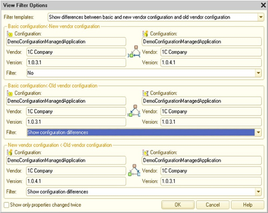
Fig. 759. Preview filters settings
The filter is used to find out the changes in configurations by selecting the objects for comparison and setting the differences display modes.
The main (current) configuration, the new and the old vendor configurations are the objects of comparison. So, the filter settings window has three sections that are similar in attribute details. Each section is intended to configure the comparison mode for any pair of configurations.
With filter settings, you can set differences preview modes across all configurations at once.
To compare easily, you can use a filter template. The template has the most common variants of settings combinations.
The user makes a decision to merge based on change data and support rules.
38.3.5. Template directory description file
When configuration templates (including updates) are located on HTTP (S) or FTP resources, you need to specify a list of configurations located on a particular resource. You can do it using the v8cscdsc.lst template directory description file. This file is located in the root directory of the configuration templates located on HTTP (S) or FTP resources.
This file is used to check for updates on a particular resource while executing the Configuration – Support – Update configuration command.
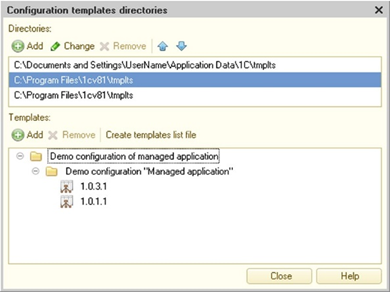
Fig. 760. Creating a template list file
To create and edit the template directory description file, select the item Configuration – Support – Configuration and update templates.
The Directories table contains a list of template directories acquired from the 1CEStart.cfg file. The Templates table lists templates that are available in the selected template directory.
Editing the configuration template directory is to remove template elements from it (or templates together with elements in its entirety) and adding configuration templates to it from other directories.
To add templates to the directory, select the Add command of the Templates table command bar. This opens an assistant to select a directory and template items.
You need to select a directory to add the configuration templates from, and then select items that are missing in the current directory.
To remove templates from the directory, select the Delete command in the Templates table command bar. This opens the deletion dialog box. Next, select the desired deletion method (only the specified items or templates including these items in its entirety) and click OK.
To create a template catalog description file, use the Create template list file command from the Templates table command panel. This must be performed to save the changes made to the template directory description.
After that, move the template catalog (along with the catalog description file) to the required external resource.
The general approach to working with templates located on HTTP (S) or FTP resources is as follows:
-
A directory is created on the local computer disk where the templates published on external resources will be located.
-
All the templates that are to be placed on external resources, are installed in this directory.
-
In Designer, in the Configuration template directories window mentioned above, the directory with templates created at step 1 is added to the Directories list.
-
In the Configuration template directories window, a template catalog description file is created (the Create template list file button). To do this, click on the template directory added in step 3.
-
Then you need to move the template directory (along with the template directory description file) from the local computer directory to HTTP (S) or FTP resource.
Chapter 39. Service features
1C:Enterprise includes many different service features and auxiliary modes. Their description is given in this Chapter.
39.1. Switching between application windows
39.1.1. Window states (window display modes)
39.1.1.1. Setting window display mode
Windows can be arranged on the screen in different modes, such as:
-
MDI. A window is displayed inside the work area.
-
Floating mode. Windows can move freely across the screen (not only within the work area).
-
Docked mode. Windows are "pinned" to the borders of the work area.
-
Auto-hide mode.
To change the window display mode, select the desired mode from the window header context menu.
Floating windows are always displayed over windows in all other modes. If several windows are in the Floating mode, the active window is displayed on top of the other windows.
Windows in the Normal and Floating mode are can be attached to each other. If two windows in the same mode have the Dockable property set (in the context menu of the window header), these windows can be docked to each other. To dock windows in the MDI state, hold down Shift while dragging the windows. You can also dock windows that are already docked to other windows.
If the Dockable option is not applied, you cannot select the Docked or Autohide options.
For windows with the Docked and Autohide options, the Dockable option is always selected and cannot be changed.
The Docked state requires special discussion. In this mode, the window can be:
-
Docked to the Designer window border.
-
Docked to a border of another window with the Docked mode set.
-
Displayed on top of another docked window (stacked windows).
If the Docked mode is set for a window, this window is docked to a border of the work area or to another window in the Docked mode.
To resize a docked window, move the pointer to the free (facing the work area) border and drag it.
If a window is in Floating mode, and its border is dragged close to the work area border or another Docked window, the window borders may change abruptly. If you release the mouse button at this moment, the window docks and its state changes to Docked.
You can change the state of docked windows by dragging them. To move a window, left click and hold the window header and drag the window to another location. This changes the window state to Floating.
There are several ways to dock multiple windows to one side of the Designer window or other window. Windows can be arranged in layers where each window occupies the entire side of the work area of the Designer window or other window. You can arrange windows in a sequence, so that each window is located in a single layer along the border of another window. If there are more than two docked windows, you can arrange some of them to be stacked in layers and the others in a sequence.
To move a docked window on top of another window (create stacked windows), do the following:
-
Drag the window.
-
Move the window so that its header appears on top of the header of another docked window, while the contour of the window being dragged must have the tab contour at the bottom.
-
Release the mouse button.
As a result, the tabs are displayed at the bottom of the docked window. The tab text matches the window header text. Each tab contains a docked window.
Click the tabs to switch between the windows.
Clicking Close in this case closes only the active tab.
To detach stacked windows from each other, drag one of the window tabs away (when a window is ready to be detached, its border changes).
You can change the order of tabs by dragging them within the tab area.
If some windows are docked to each other, you can dock more windows to them by dragging new windows to the tab area instead of the header. When doing so, you can choose a position for the new window tab among the existing tabs.
You can also arrange windows in the Autohide mode. If the Autohide mode is selected, an additional bar appears on the side of the work area. This bar contains window tabs, including a tab for the current window, while the window itself is docked to this side of the work area. The bar location is determined by the position of the Docked window. In this state a window is displayed on the screen while it is active. Once you switch to another window, the previous window is hidden. To display this window, hover the mouse over the window tab (do not click it). Once you move the pointer away, the window is hidden.
For docked windows, in addition to the stacked mode another mode can be set as well. For example, it can be convenient to set the Autohide mode. In this case, an additional line will contain only tab icons. When hovering the mouse pointer over any tab icon, the window is displayed, and its name is shown in the additional line.
39.1.1.2. Restoring default window positions
You can change position, size, and status of windows as described above. At the same time, when closing, the latest display parameters of the window are saved and applied automatically when the window opens again.
To restore the original position, size and status of the window, select the Restore window position command in the context menu of the window header (or window pane header). This will reset the parameters to default values. The window is closed and re-opened with the new display parameters.
39.1.1.3. Selecting window mode for object forms
You can configure the window state mode for applied object forms at the first opening in 1C:Enterprise mode. For this purpose, you can use the Window properties category for each object form.
Window state. Indicates the state of the window at the first opening. If the Normal state is selected, the window state cannot be modified.
Dockable window. Indicates that the window can be attached to other windows.
Window location. If Auto is specified, the window position is determined based on the state and dimensions of the work area. If you specify the Center option, the window is placed in the center of the work area when it is first opened. If Don't overlap owner is selected, location of a subordinate window is determined so that it does not overlap the owner window or control (if the work area has free space). If there is no place to display it, the subordinate window attempts to expose the left part of the owner window provided that 50% of the owner width can be unclosed.
The position of the docked window. It is determined by the position of the window of the form in the docked state relative to the work area.
Change size. Permits or forbids changing the size. The DontChange value does not affect the ability to change the size of a window in the Docked and Autohide modes.
39.1.2. Managing windows
Use the Windows dialog box to manage the open windows. This includes switching to a selected window, saving changes, arranging windows, and closing one, several, or all windows.
To view the list of all open windows, click Windows – All windows. Only the windows with MDI status are included in the list.
If the content of an open window is modified, the window is marked with an asterisk (*) in the list, to the left of the window name.
All the operations available in the dialog box are applied to one or several selected windows. Use the standard item selection methods.
Operations that can be performed with a single window or a group of windows are described in the following table.
| Button | Action | Number of selected windows (condition) |
|---|---|---|
| Activate | Activate the selected window. | One |
| Save | Save the changes for some types of documents that support this operation (for example, text and spreadsheet documents). | Any number |
| Close windows | Close the selected windows. | Any number |
| Arrange | Arrange the selected windows. Horizontal. Arrange the selected windows from left to right. Vertical. Arrange the selected windows from top to bottom. Cascade. Arrange the selected windows in a cascade. | More than one |
| Join | Join two windows. | Joining is allowed |
| Detach | Detach joined windows from each other. | |
| OK | Closes the Windows dialog box. | Any number |
39.1.3. Using "New window" mode
You can use Windows – New window to make a copy of any form editor, text editor, or spreadsheet editor window. This will open a new window instance, an exact copy of the current window, in the work area of the program. Its contents will be identical to the original. The window number will be displayed in the header.
This mode is convenient for viewing, comparing, and editing information in a window. Any changes in any window instance are displayed in all window instances.
We recommend using this mode, if the window is a configuration object form with items distributed across several pages and you need to view these pages at the same time or view the module and form dialog box simultaneously. Similarly, this mode allows you to edit long texts or templates. Also, one window instance can be used to view one part of a text or a template and the other window instance can be used to view the other part.
39.1.4. Service windows
While using Designer, service windows will provide various support information. These windows include:
-
Message window
-
Window with search results from all texts
-
Text templates
-
Syntax Assistant
The first two types of windows are automatically displayed if needed (text templates and Syntax Assistant are displayed upon user request).
The purpose of each window is described in the corresponding sections of this manual. This section will outline the general principles of operations with such windows.
To manage windows, you can use context menus that are opened from the window title bar and within the window. The first menu option is used to manage the window itself (for details, see Window states (window display modes)), while the second menu option operates window contents.
The contents of the message window are not automatically cleared. To clear it, use the Clear command from the context menu.
39.1.5. Closing windows
To close any window, click Close or press Shift + Esc or Ctrl + F4.
39.1.6. Windows navigation history
Windows navigation history is stored during the session. For example, you can use this tool to return to the initial window when navigating to the place where variables, procedures and functions are defined.
While using windows history, you can move back within the history by clicking Windows – Move back. To move forward within the history, click Windows – Move forward.
39.2. Setting Designer parameters
To set up various Designer parameters, use the Tools – Parameters property.
The Parameters window is organized as a card type file. All available parameters are combined in groups. To access controls of a specific group, click on the corresponding window tab.
39.2.1. Overall
This tab contains the only parameter that defines the operation mode and interface for Designer. The parameter is Edit configuration for startup modes.
This parameter can take two values:
-
Managed application. The system hides interface items used for editing properties and objects in the ordinary run mode.
-
Managed application and ordinary application. No interface items are hidden, and the user can edit the configuration in both ordinary and managed mode at the same time.
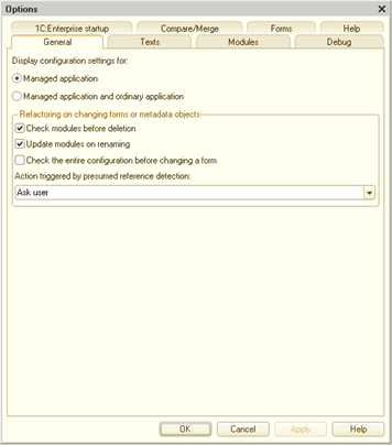
Fig. 761. General parameters
This parameter is stored across the infobase. It allows you to set it up for each particular infobase. By default, the parameter is set to editing mode for managed mode. However, if you load-up the Default run mode configuration with this property set to Ordinary (or this property changes interactively), the parameter is set to editing of managed and ordinary run modes.
Below is a list of Designer UI elements that are hidden when the parameter is set to the managed run mode:
-
Styles metadata tree branch.
-
Interfaces metadata tree branch.
-
Main interface configuration property.
-
Selection of main interface in the user editing dialog box.
-
Form tab in Designer parameters.
-
Default run mode drop-down list on the Modules – Validation tab.
-
Use managed forms in ordinary application configuration property.
-
Use ordinary forms in managed application configuration property.
-
Interfaces tab in metadata editing windows.
-
Open ordinary application module configuration context menu item.
-
Flag of managed form creation in the form wizard.
-
Output form wizard commands.
-
Client (ordinary application) common module property.
-
Additional tab on the Forms tab of the configuration object editing window.
-
Interactive activation processing and Before execute interactively event handlers at a business process route point of the Activity type.
Refactoring if forms or metadata objects are changed group of parameters allows you to set up how the platform will react when making these changes:
-
Check modules before deletion. If the checkbox is selected, the platform will search if an object to be deleted is used somewhere. If the object is used (or might be used), the platform will ask for additional confirmation for deleting and will display the search results.
-
Apply changes to modules if renaming. If the checkbox is selected, the platform will search for the old name of the object, that was used before renaming the configuration object and will apply changes to the code.
-
Check the entire configuration when changing forms. If the checkbox is selected, when renaming or deleting the platform will check if the old name of an attribute, element or managed form parameters is used somewhere. The module form check is done in any case, regardless of the checkbox selection.
The Actions triggered by presumed reference usage parameter allows you to set up refactoring if it is impossible to unambiguously define whether the object to be deleted or renamed is used somewhere:
-
Ask a question. For each case of a presumed reference use, a question will be asked.
-
Continue operation. The required action and replacement for actual usage cases will be performed. Presumed usage cases will be displayed.
-
Cancel operation. In this case, the action will not be performed and the search results of the object reference usage will be displayed.
39.2.2. Texts
Controls in the Texts tab are used to configure the text document editor.
Drag and drop text. In the text editor, you can use drag&drop mode to move and copy text blocks.
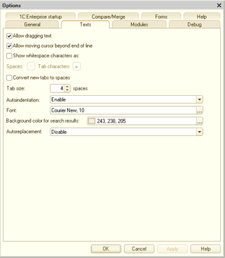
Fig. 762. Text editing parameters
Allow moving cursor beyond the end of lines. If this checkbox is selected, the cursor can be positioned beyond the end of the line. If this checkbox is cleared, the cursor position is limited by the Line break character.
Show spaces and tabs. If this checkbox is selected, the spaces and tab characters will be displayed in the text. Use this option to verify the text formatting. If the Show spaces and tabs property is set, the Space and Tabs properties become available for entering characters that will be used to display spaces and tabs:
-
Space. Specifies the symbol used to display spaces.
-
Tabs. Specifies the symbol used to display tabs.
Replace tabs when typing. If this checkbox is selected, the typed tabulation symbols will be replaced with the number of spaces specified in Tab width property.
Tab width. Maps the tab character to the number of characters when entering text.
Autoindentation. Shows whether an auto indent is added after you type the Line break character (press Enter).
Font. Selecting a font for text input. We recommend using a fixed-width font for module text input (for example, Courier New).
Background color for search results. Allows you to set a background color for search results in text editor.
Auto-replacement. If this property is enabled, the entered text, that corresponds to the text in the Automatically replace string attribute of the template, will be automatically replaced with a template text. If the Enable with tooltip option is selected, the template text is displayed after a short pause while the text to be replaced is being entered. If the Only tooltip option is selected, template text will be displayed after a brief pause, but there will be no text replacement.
To replace input text with a template text, click Space or Enter after typing a string.
39.2.3. Modules
TheModules tab controls are used to configure the color highlighting of module syntax, auto-indentation, tabulation width for modules and to set up grouping. The settings are grouped into sections. Each section is located on a separate tab.
39.2.3.1. Setting editing parameters
The Edit tab is used to set color for highlighting syntax in modules, auto-indentation, and tabulation width for modules.
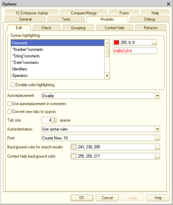
Fig. 763. Module texts editing settings
Syntax highlighting. It's easier to perceive module text if certain syntactic constructs (constants, names, operators, comments, and so on) are highlighted. Color is also used to check whether module text has been entered correctly. If you enter the operator name incorrectly, it will not be highlighted with a required color. You can choose a different color for every construct (constant, name, operator, comment, and so on).
Among syntactic constructs that can be color highlighted, let us individually discuss Current ID, Selected ID, and Block borders.
Color selected for the Current ID construction is used to highlight all uses of any ID, with cursor for text editing "inside". No additional actions are needed for highlighting. You just need to point the cursor on the ID.
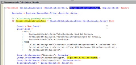
Fig. 764. Current ID
Color selected for the Selected ID construction is used for selecting all uses of an ID, that is fully selected (by double clicking or otherwise).
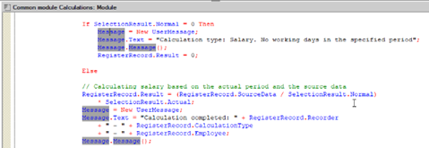
Fig. 765. Selected ID
Note. Tip. If you do not need to automatically select all the IDs with a cursor "inside" of them, you can select a Current ID construction color, that matches the IDs construction. After that, it will be possible to see the uses of any ID by selecting it.
When highlighting IDs, string constants that follow the rules of IDs generation are going to be highlighted as well.
Note. Note. Default colors selected for the Current ID and Selected ID constructions match the background color and need additional setup.
Color selected for the Block borders construction is used for highlighting paired brackets (), (, ], [) and keywords, that are used together, for example Procedure ... EndProcedure, If ... Otherwise ... EndIf, and so on. Highlighting is done only if the cursor is "inside" a keyword or a bracket.
Disable highlighting. If set, module text is displayed as ordinary text and the color highlighting setting is unavailable.
Auto-replacement. If this property is enabled, the entered text that corresponds to the text in the Automatically replace string attribute of the template is automatically replaced with a template text. If the Enable and show tooltips property is enabled, the template text is displayed after a brief pause while the text to be replaced is being entered. If the property is set to Only tooltip, tooltip text is shown after a brief pause when you type the replaceable text.
To replace input text with a template text, click Space or Enter after typing a string. If the Auto-replacement property is set to Disable or Only tooltip, these actions are not performed.
Use auto-replacement in comments. If set, template text is displayed when you enter a text to comments, that matches the template text.
Replace tabs when typing. If this checkbox is selected, the typed tabulation symbols will be replaced with the number of spaces specified in Tab width property.
Tab width. Specifies the number of Space characters equivalent to one tab character.
Autoindentation. Shows whether an auto indent is added after you type the Line break character (press Enter). If Syntax value is selected, module text input is performed according to the current syntactic construction.
Font. Selecting a font for text input. We recommend using a fixed-width font for module text input (for example, Courier New).
Background color for search results. Allows you to set a background color for search results in text editor in 1C:Enterprise language.
Context help background color. Allows you to set a background color for a context help in text editor in 1C:Enterprise language.
39.2.3.2. Setting module check parameters
The Check tab is used to set module check modes.
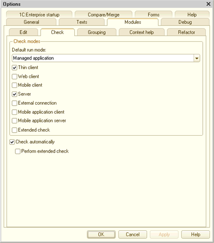
Fig. 766. Setting module syntax check
Module check settings are used to select a suitable environment for compilation. Execution environment includes common modules with a corresponding flag and modules that are used in particular executive modes (managed application module, session module, and so on). If executive environment compilation is successful, the module that initiated syntax check is verified. Moreover, the number of performed check passes (including executive environment compilation) is equal to the number of check marks set in dialog box. Modules that do not exist in the selected check mode are not checked. For example, an ordinary application module will not be checked if you select the Thin client check mode.
The Default run mode parameter allows you to quickly change the module check settings. The drop-down list of this parameter depends on the Edit configuration for startup modes parameter (see Overall). If this parameter is set to Managed application, the Ordinary application mode is missing from the drop-down list, and the Thick client (ordinary application) mode is missing from the list of check modes. If the Edit configuration for startup modes parameter is set to Managed application and ordinary application, all possible options are present in the drop-down list and the list of check modes. When opening the dialog box, the value of the Default run mode parameter always matches the Default run mode configuration property value.
You can set a different set of check modes for each run mode. To do this, specify the required mode in the Default run mode parameter and then set the required set of modes using the checkboxes below in the dialog box. By default, Designer sets the following check modes:
-
Managed application: Thin client and Server.
-
Mobile application: Thin client, Mobile application, Server, and Mobile application client.
-
Ordinary application: Thick client (ordinary application).
After changing the set of checkboxes for the selected mode, save the parameters (click Apply or OK). After changing the Edit configuration for startup modes parameter value (see Overall), Designer will restore the set of check modes that it had when the settings were last saved (for the selected run mode).
The same checks performed using this dialog box can be performed by the /CheckModules command of the Designer batch run command line. You can see parameters of the command below, in description of each check mode.
Depending on the selected mode, there will be checks with the following preprocessor commands:
-
Thin client:
-
Preprocessor commands: Client, AtClient, and ThinClient.
-
/CheckModules command parameter: ThinClient.
-
-
Web client:
-
Preprocessor commands: Client, AtClient, and WebClient.
-
/CheckModules command parameter: WebClient.
-
-
Mobile client:
-
Preprocessor commands: Client, AtClient, and MobileClient.
-
/CheckModules command parameter: MobileClient.
-
-
Mobile client (in standalone mode) and mobile standalone server:
-
The check consists of two steps:
-
First check: Client, AtClient, and MobileClient.
-
Second check: Server, AtServer, and MobileStandaloneServer.
-
-
/CheckModules command parameter: MobileClientStandalone.
-
-
Server:
-
Preprocessor commands: Server and AtServer.
-
/CheckModules command parameter: Server.
-
-
External connection:
-
Preprocessor commands: ExternalConnection.
-
/CheckModules command parameter: ExternalConnection.
-
-
Mobile application client:
-
Preprocessor commands: Client, AtClient, and MobileAppClient.
-
/CheckModules command parameter: MobileAppClient.
-
-
Mobile application server:
-
Preprocessor commands: Server, AtServer, and MobileAppServer.
-
/CheckModules command parameter: MobileAppServer.
-
-
Thick client (ordinary application):
-
Preprocessor commands: Client, AtClient, and ThickClientOrdinaryApplication.
-
/CheckModules command parameter: ThickClientOrdinaryApplication.
-
-
Extended check:
-
Preprocessor commands: not used.
-
/CheckModules command parameter: /ExtendedModulesCheck.
-
If the Check automatically checkbox is selected, module text will be automatically checked for syntax errors (when recording or closing). If the Including extended check checkbox is selected, calls to object properties and methods using a dot are verified for a limited number of types. Also, a check is conducted to determine whether the settings specified by a string are correct for a limited number of methods. For more information on check types, see Centralized configuration verification.
39.2.3.3. Setting group parameters
The Grouping tab is used to set up grouping and folding modes for various syntactic constructs. The table lists syntax types of constructions by lines.
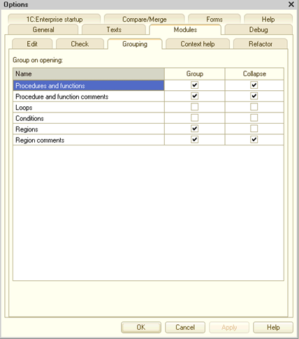
Fig. 767. Setting groupings
Selecting a checkbox in the Group column will cause the syntactic construct to automatically group. Note that only syntax structures of the second nesting level can be grouped.
If the Collapse checkbox is selected, the syntax structure will automatically collapse when a module is opened.
39.2.3.4. Context tooltip settings
The Context tooltip tab is used to specify the settings for opening the context tooltip when module text is being entered.
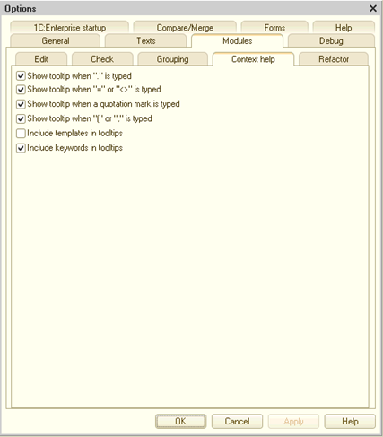
Fig. 768. Setting context tooltip
If the Show tooltip when "." is typed checkbox is selected, a context tooltip is automatically displayed when you type a dot ".".
If the Show tooltip when "=" or "<>" is typed checkbox is selected, a context tooltip is automatically displayed for system enumeration value selection when you type the characters "=" and operator "<>".
Selecting the Show tooltip when a quotation mark is typed checkbox enables the context tooltips for parameters of some methods if the parameter is set by a string.
Selecting the Show tooltip when "(" or "," is typed checkbox enables the context tooltips for parameters of system procedures and functions, including application procedures and functions, with comments designed in a specific way (see
Context help for module text input).
If the Include templates in tooltips list checkbox is selected, templates with auto-replace strings defined are listed.
If the Include keywords in tooltips list checkbox is selected, all keywords (such as If, Procedure, Loop, Return, and so on) are included in the list.
39.2.3.5. Refactoring settings
On the Refactoring tab, you can set up platform behavior when opening legacy synchronous calls search (see Using legacy synchronous calls).
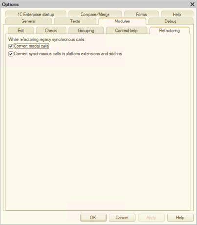
Fig. 769. Refactoring setting
The Convert modal calls checkbox selection defines whether the refactoring feature will process the modal method calls with dialog boxes or not.
The Convert synchronous calls of extensions and add-ins checkbox selection defines whether the refactoring feature will process synchronous operation methods for files, extensions and add-ins.
39.2.4. Debugging
On this tab, you can set up which protocol will be used for application debugging. If you use the HTTP protocol on this tab, the parameters will be set for this protocol.
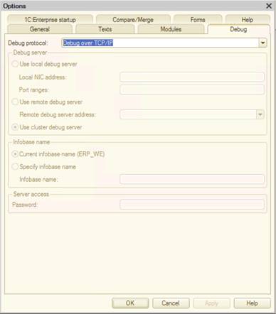
Fig. 770. Debug parameters
In this dialog box, Designer prompts some default values depending on the attached infobase. However, the developer can set up these parameters individually if required.
The Debug server group allows you to specify where the debug server to be used is located.
- Use local debug server. Mainly used to debug using the file mode of the infobase. If several network cards are installed on the computer, specify which network card will be used for debugging. This is done by filling in the IP address of the required network card in the Local NIC address field. In the Port ranges field, you can fill the range of the network ports that will be used for debugging. A port that to be used by the debug server will be selected from the specified port range (ranges). The port range is filled in using the " :" symbol, the ranges are separated using the "," symbol. For example: 1560:1591, 2560:2591, 7700-8000.
In this case, when starting the application to be debugged, a debug server will be started and it will manage the debug in this infobase.
This mode is automatically selected for file mode infobase operations.
-
Use remote debug server. In this case, Designer will try to connect to a remote debug server, its address and port are filled in the Remote debug server address property.
-
Use cluster debug server. In this case, Designer will use the connected debug server deployed in a server cluster, to perform debugging. To enable debug in server cluster, you need to start this cluster in debug mode, using the /debug keyword. In this case, when starting the application to be debugged, a separate debug server won't be started.
This mode is automatically selected when working with client/server mode infobase
Infobase name group is used to specify the name of the infobase, under which the debugger will register on the debug server, specified in Debug server group:
- Default. Will be selected in case Designer uses the file mode of the infobase. In this case, the DefAlias name will be always used.
Current infobase name ("name"). Will be selected in case Designer uses the client/server mode of the infobase. The infobase's name used in server cluster will be used as the infobase name.
- Use specified infobase name. If required, you can fill in a custom name in the infobase name field. This setup might be required when you need to debug the configuration according to data of a different client/server infobase with a similar configuration.
After changing the settings on this page, you will need to restart Designer.
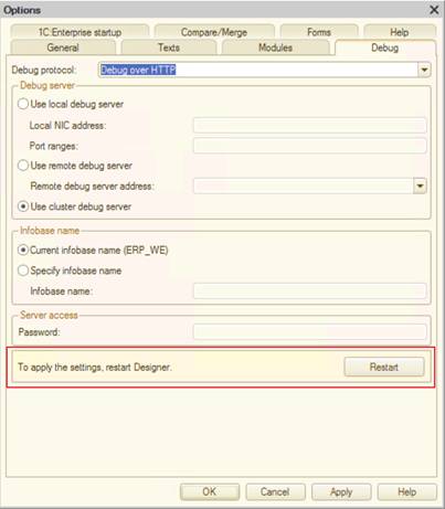
Fig. 771. Restart after changing the debug parameters
39.2.5. 1C:Enterprise startup
39.2.5.1. General parameters
On this tab, you can select the application to be started, and user selection when starting 1C:Enterprise.
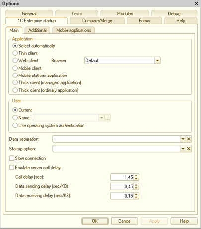
Fig. 772. 1C:Enterprise startup parameters
When starting 1C:Enterprise from Designer, the client to be loaded is specified in Application group.
If the mode is set to Select automatically, the 1C:Enterprise selects the client type depending on the configuration Default run mode and Run mode property of the user that starts the 1C:Enterprise. If configuration properties and user properties are not specifically indicating something, then:
-
If the Default run mode property is set to Ordinary, thick client will be started in ordinary mode.
-
If the Default run mode property is set to Managed application, thin client will be started.
If a specific client type startup is required at 1C:Enterprise startup from Designer, you need to set it manually (items under Select automatically). When specifying the start of the web, you can specify the web browser that will be started:
-
Default web browser
-
Google Chrome,
-
Microsoft Edge,
-
Microsoft Internet Explorer
-
Mozilla Firefox
-
Safari,
-
Yandex Browser
The list of available web browsers depends on the operating system which runs Designer. For example, Safari will only be available when running macOS, and Microsoft Internet Explorer will only be available when running Windows.
When starting the web client from Designer, the platform version with an uploaded earlier infobase is checked. If the versions are different, the user receives a message suggesting to perform the publication again. If the answer is positive, opening the infobase publication dialog box is initiated.
If mobile client is selected as a client application, you can specify its mode: mobile client mode (Standalone mode is set to Do not use) or mobile client in standalone mode ( Standalone mode is set to Use). If Standalone mode is set to Auto, standalone mode will be used, if an application has standalone configuration components duly assigned.
The user that starts the 1C:Enterprise from Designer is defined in User group:
-
Current. User from the user list.
-
Name. A specific user is selected (the /N command-line option analog). The required user can also be selected from the list. To do it, use the "..." button, located on the right side of the field.
-
If the Use operating system authentication checkbox is selected, the user will be selected using the operating system authentication (the /WA command-line option analog).
Data separation. Allows you to specify the separator's values in a way that is used to specify them for the /Z option (for details, see Client application command line). The string specified in this field must match the specifying separators values rule, however, it must not have quotation marks framing the values, when specifying these values in the /Z parameter. For example, if you specify the /Z "-1, +4" option in the command line, specify -1, +4 in the Data separation field. 1C:Enterprise stores different options for separator values input and allows you to switch between them.
Startup parameter. Startup parameter (the /C command-line option analog) that is available for processing through the LaunchParameter global context property.
Low connection speed. Allows you to enable or disable the low connection speed mode at thin client startup. Checkbox selection is saved for the specified infobase. The checkbox is cleared for an infobase with slow connection speed startup mode not set at the base list. If the checkbox is selected, 1C:Enterprise starts using slow connection speed.
For an infobase with a slow connection speed startup mode set in base list, the checkbox is displayed in gray. If the checkbox is cleared, 1C:Enterprise starts using normal speed. The checkbox is an analog of the /O command-line option.
Emulate delay on server calls. The checkbox enables emulation of the thin client operation under the conditions of significant time delays, that are caused by interactions with the server. This feature is turned off by default.
Call delay, sec. Defines the delay duration for each server call by a client application.
Data sending delay (sec/kB). Defines the delay duration when transferring data to the server. Time is indicated by 100 bytes of transferred data.
Data receiving delay (sec/kB). Defines the delay duration when receiving data on the server. Time is indicated by 100 bytes of received data.
Note. Note. Default values allow GPRS connection emulation.
You can also enable the server delay emulation mode in the command line: /EmulateServerCallDelay [-CallXXXX] [-SendYYYY] [-ReceiveZZZZ].
39.2.5.2. Additional parameters
Additional parameters on this tab can be helpful when developing applications (in particular, for debugging).
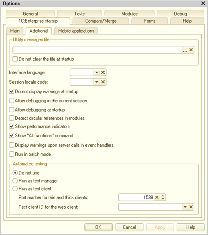
Fig. 773. Additional 1C:Enterprise startup parameters
Service messages file. To save service messages to a file automatically, enter its name in the parameter (same as the /OUT command-line option).
Do not clear file before startup. If this checkbox is selected, during the next startup, messages will be added to the specified file (the /OUT command-line option with the NoTruncate key analog).
Interface language. It is used to specify the national language of the interface (the /L command-line option analog).
Session localization code. It is used to specify the session locale code (the /VL command-line option analog).
Do not display warnings on startup. If this checkbox is selected, the following startup messages are suppressed:
-
Database configuration does not match stored configuration. Continue?
-
Your computer capabilities are inadequate to edit configuration help. To edit HTML documents, install Microsoft Internet Explorer version 6.0 or later.
-
Your computer capabilities are inadequate to edit HTML documents, including help sections. To edit HTML documents, you must install Microsoft Internet Explorer version 6.0 or higher. HTML document editing will be unavailable during this session (parameter passed through the /DisableStartupMessages command-line key analog).
Allow debugging mode. If the checkbox is selected, debugging is available when the application is started in 1C:Enterprise mode (analog of the parameter specified in /debug -tcp or /debug -http command-line option).
Start debugging on startup. If the checkbox is selected, when starting 1C:Enterprise, connection is performed automatically. When using HTTP protocol to debug, this setting is the same as when using the /debug
- http -attach command line key.
Note. Note. If 1C:Enterprise starts from Designer using the Debug – Start debugging menu item, the debugging mode is enabled automatically (regardless of the Enable debugging mode and Start debugging on startup checkboxes).
Check 1C:Enterprise language circular references. If this checkbox is selected, the client application (thin or thick client) will check the circular references when operating with 1C:Enterprise language, when started from Designer. This checkbox is an analog of the command line /EnableCheckScriptCircularRefs key.
Display performance indicators. If this checkbox is selected, a button is added to Favorites and History panel when starting 1C:Enterprise. When clicking the button, a window with current statistics on interaction with 1C:Enterprise server is displayed (analogue of the /DisplayPerformance command line parameter).
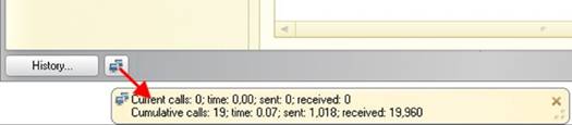
Fig. 774. Display server calls
For more information, see Server call history.
Technician mode displays the Service and settings – Advanced tools menu (see fig. 775) and can be used instead of the /TechnicalSpecialistMode command-line option. This command call displays a form with a list of all applied objects you can use (used in managed mode of thick client as well as thin and web client). The menu command is turned off by default.
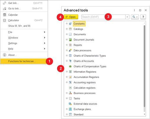
Fig. 775. Using the "Advanced tools" form
If the Advanced tools command display is enabled, follow these steps:
-
Open the Advanced tools form by clicking Service and settings – Advanced tools.
-
The necessary configuration object is selected from the configuration objects tree.
-
As an alternative to step 2, you can select required objects using the search string of the Advanced tools form.
-
The double-click on the selected object of configuration or clicking Open is the last step. The selected form will be opened after this step is performed.
The search string is activated by the Ctrl + F key combination or as of text typing start in the configuration object tree. When the search string is used, the configuration object tree is switched to the flat list (without hierarchy) mode and returns to tree mode when the search is aborted. The search with the help of this mechanism selects the configuration objects and forms which match the search string for display. No other objects will be displayed in the list. To cancel the search, press Ctrl + Q.
The search is performed by representation and uses the following algorithm:
-
Search is carried out by the beginning of the word.
-
If a word contains letters and digits:
-
A sequence which contains letters only is deemed a separate word.
-
A sequence which contains digits only is deemed a separate word.
-
-
In a word consisting of digits, leading zeros can be both significant and insignificant simultaneously.
-
An item is deemed to be found (including if this item contains subordination) if one of the following conditions is met:
-
Item presentation contains all the words you searched for.
-
Item presentation contains at least one searched word and its parents contain the remaining words.
-
Therefore, if all registers whose presentation contains the word "expenses" must be found, you can specify "expenses register" in the search string and get the following result (for Sales management 11.4.3):
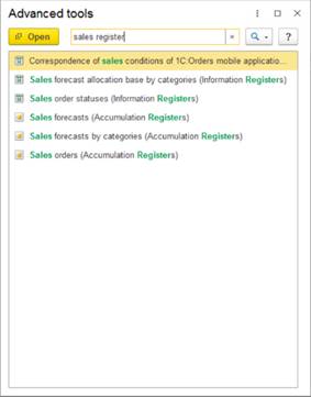
Fig. 776. Search result
To search in the displayed information of the tree (group names and open tree branches), open a usual search window (press Alt + F). In this case, the cursor will be on the first occurrence of the searched string and F3 (go to the next search result) and Shift + F3 (go to the previous search result) can be used to move in the search results.
Note. Note. Forms opened from the Advanced tools window always appear in the auxiliary window of the application.
In the Advanced tools window, you can also find Standard functions used for execution of some standard procedures: viewing the list of active users, deleting marked objects, and so on.
When technician mode is enabled, several features useful for application debugging and maintenance become available:
- You can get a full name of any opened form in the managed application or command interface element. To do this, right-click the form header or command interface element and select Information for technician.
This command is added to the context menu available for the following UI elements:
-
Form header Not supported in system forms
-
Element of open items panel
-
Element of functions menu
-
You can get access to the opened form in Designer. It is possible only if the client application is started in debug mode in addition to the enabled technician mode. In this case, right-click the form or a command interface element and select Open in Designer. The same button will be available in the window that appears after clicking Information for technician.
This command is added to the context menu available for the following UI elements:
-
Form header Not supported in system forms
-
Element of open items panel
-
Element of functions menu
In the context menu, the commands mentioned above look as follows:
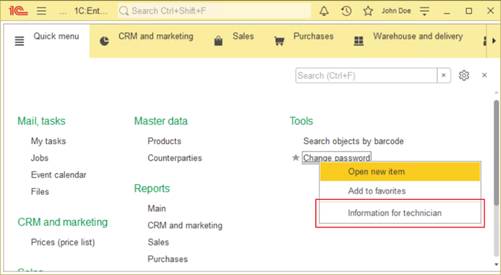
Fig. 777. Special features for technician
The dialog box that displays the full form name looks as follows:
Fig. 778. Information for technician
As already mentioned, the Open in Designer button is available only if the technician mode is enabled in the client application in debug mode.
Check server calls in event handlers. If this checkbox is selected, the /EnableCheckServerCalls command-line startup option is added from Designer to the command line of 1C:Enterprise startup.
Selecting this checkbox in the startup settings is recommended if the application can potentially have handlers of form events, where context server calls are performed. Using them in this kind of handlers is not allowed (see Specific features of using objects, their properties and methods). Breaking this rule can lead to errors in some cases of server calls usage. Mainly problems occur if the form items or its attributes change in such handler while in server call. As a result, unexpected behavior or non-obvious execution time errors may occur.
Run in batch mode. Allows you to start the client application in batch mode from Designer.
The Automated testing group is used to define the role (in terms of automated testing, see Automated testing of applications for details) of started client application when starting from Designer:
-
Do not use. Started client application is not used in automated testing.
-
Start as testing manager. The client application to be started will be used as the testing manager (the TestManager command line key will be used).
-
Start as testing client. The client application to be started will be used as testing client (the TestClient command line key will be used). For interaction with testing manager, the port specified by the Port number for thin and thick client (TPort parameter for TestClient command line key) parameter will be used. For the web client, an ID specified in ID for web client parameter is used (TestClientID command line key) will be used.
39.2.5.3. Mobile application
applicationThis tab is used to set up the parameters required for 1C:Enterprise, in order to operate with Android SDK.
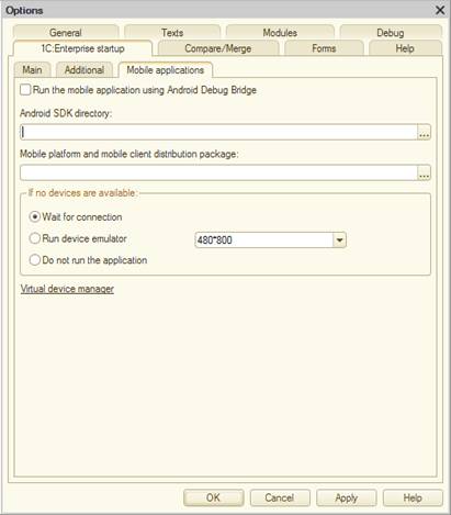
Fig. 779. Mobile application startup parameters.
Use "Android debug bridge" to start a mobile application checkbox defines the method to be used for sending the configuration to the mobile device:
-
If the checkbox is selected, the configuration is sent to the mobile device via Android Debug Bridge (ADB).
-
If the checkbox is cleared, the configuration is sent via a web server.
Android SDK directory. Defines the path to the installed Android SDK. This parameter must be specified before performing any Android Debug Bridge operations.
Mobile platform. Contains a link to the mobile platform archive. This link will be used on the mobile device or emulator. The archive must have an Android directory, with the following files in it:1cem-arm.apk(mobile platform for ARM architecture developer) and 1cem-x86.apk (mobile platform for ARM architecture developer).
The No devices available parameter group defines Designer behavior when no mobile devices are connected to the computer where Designer is operating. Or when an emulator is not started on this computer.
-
Wait for connection. In this case, Designer will wait for a physical device connection or an emulator start. Waiting is performed with no timeout.
-
Start device emulator. In this case, Designer will try to start an emulator specified in the nearby field. Emulator is created using the Android virtual device manager (included in Android SDK).
-
Refuse starting. This will interrupt the performance of the action.
Hyperlink Virtual device manager is used for starting the AVD Manager application from the Android SDK directory.
39.2.6. Comparison/merging
This tab is used to set up the parameters of add-in, that can be used to compare/merge modules.
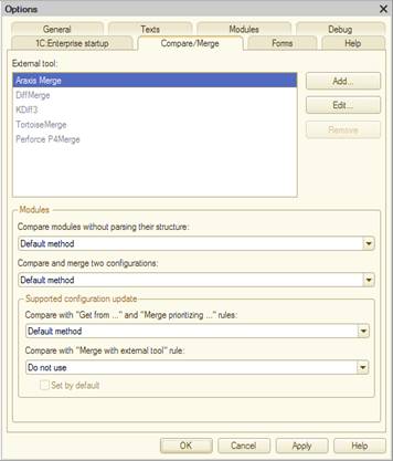
Fig. 780. Setting-up add-ins for comparison/merging
The programs that can be used for comparison/merging of files are listed in the Add-ins list (see Comparing and merging configurations).
The parameters for the following Designer add-ins are set by default:
-
Araxis Merge
-
Operating system in use: Windows
-
Website: http://www.araxis.com/merge/
-
Executable file: compare.exe
-
Supported modes:
-
Comparison of two files
-
Merging two files
-
Trilateral merging
-
-
-
KDiff3:
-
Operating system in use: Windows and Linux
-
Website: http://kdiff3.sourceforge.net/
-
Executable file: kdiff3.exe for Windows and kdiff3 for Linux
-
Supported modes:
-
Comparison of two files
-
Merging two files
-
Trilateral merging
-
Automatic trilateral merging
-
-
-
TortoiseMerge:
-
Operating system in use: Windows
-
Executable file:tortoisemerge.exe
-
Supported modes:
-
Comparison of two files
-
Trilateral merging
-
-
-
Perforce P4Merge:
-
Operating system in use: Windows and Linux
-
Website: http://www.perforce.com/product/components/perforce-visual-merge-and-diff-tools
-
Executable file: p4merge.exe for Windows) and p4merge for Linux
-
Supported modes:
-
Comparison of two files
-
Trilateral merging
-
-
-
DiffMerge:
-
Operating system in use: Windows
-
Website: https://sourcegear.com/diffmerge/
-
Executable file: sgdm.exe
-
Supported modes:
-
Comparison of two files
-
Trilateral merging
-
-
However, to use add-ins, an additional setup is required, you need to specify the path to the executable file.
Modules group is used to specify which mechanism will be used for executing a specific operation:
-
Show differences without structure. It is used to select the functionality that will be used when using a corresponding command in the configuration comparison/merging window. Selecting theOrdinary method item means that the Designer's built-in functionality will be used comparing two files contents. Also, add-ins with specified Path and Compare two files properties will be available for selection.
-
Merging settings when merging two configurations. It is used to select functionality that will be used for merging two configurations. Selecting the Ordinary method item means that the Designer built-in mechanism will be used for merging two files contents. Also, add-ins with specified Path and Merge two files properties, will be available for selection.
Supported configuration update group describes 1C:Enterprise behavior, when updating a supported configuration.
-
"Take from", "Merge with priority" modes. Defines what will be used for interactive merging. Selecting the Ordinary method item means that the Designer built-in mechanism will be used for merging (two-way). Also, add-ins with filled-in Path and Trilateral merging properties, will be available for selection.
-
Merge using add-in mode. It is used to specify which add-in will be used for trilateral merging and allows managing the availability of the Merge using add-in mode in the configuration update settings. Add-ins with Path and Trilateral merging properties filled are available for selection.
If this property is set to Not used, then the Merge using add-in feature disappears from the merging mode settings. When saving Designer settings all merging modes, where the use add-in property is set, are replaced with Take from new vendor configuration mode (if the update main configuration window is open).
If an add-in is specified in this property, and the use by default checkbox is selected, when saving settings the Merge using add-in merging mode is selected.
It is possible to add a native file content comparison utility. To do so, click Add and specify all the parameters in the opened dialog box.
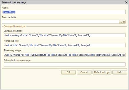
Fig. 781. Add-in settings
The Name field is used to specify the presentation of the comparison program.
Specify the path to the utility in the Executable filefield (seefig. 781). If the path to an executable file is not specified, this add-in is displayed in gray color in the Add-ins list and these programs cannot be selected in other comparison and merging settings. See fig. 780. In fig. 780, DiifMerge, TortoiseMerge, and Perforce P4Merge are displayed in gray color. For the Araxis Merge and KDiff3 programs, a path to the executable file is specified.
In the following fields (Command line group), the command line parameters are defined for the add-in that is used for any operation from Designer:
-
Comparison of two files. Two files contents are interactively compared.
-
Merge two files. Two files contents are interactively merged (with a feature that allows modification of the acquired result).
-
Trilateral merging. Three files contents are interactively merged (with a feature that allows modification of the acquired result).
-
Automatic trilateral merging. Automatic merging of three files contents. Is not performed interactively if there are no conflicts when merging.
The command line parameters that will be passed to the add-in for executing operations are set for each field with an identical name. If an operation is not supported by the utility, the corresponding field is left blank.
When forming the command line you can use the following predefined parameters:
-
%baseCfg. Path to file from the main configuration.
-
%secondCfg. Path to file from the second configuration. The second configuration can be:
-
Configuration from file
-
Vendor configuration (new vendor configuration if updated)
-
Configuration from configuration repository
-
Database configuration
-
-
%oldVendorCfg. Path to file from the previous vendor configuration.
-
%merged. Path to the resulting file (merging result).
-
%baseCfgTitle. Window title for the file from the main configuration.
-
%secondCfgTitle. Window title for the file from the second configuration.
-
%oldVendorCfgTitle. Window title for the file from the previous vendor configuration.
39.2.7. Forms
This tab is used to configure the display parameters of the initial form editor preview window.
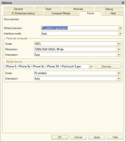
Fig. 782. Preview setting
The Use assignment and Interface parameters determine in which option the preview will open when the form editor is opened. If the Use assignment parameter is set to Application for platform, then the Interface parameter will allow you to select which application interface will be displayed in the form editor preview window. If the Use assignment parameter is set to Application for mobile platform, then the interface cannot be selected and the preview window will always display a preview of the form for the mobile platform.
Personal computer group contains parameters that are relevant for previewing a form intended for use on a personal computer:
-
Scale. Defines the default scale value.
-
Resolution. Defines the default resolution of the preview panel.
-
Rotation. Defines which screen orientation will be used by default:
-
Auto. The horizontal orientation is used.
-
Horizontally, Vertically. Indicates the corresponding orientation of form.
-
Mobile device group contains parameters that are relevant for previewing a form intended for use on a mobile device:
-
Mobile device. Allows you to specify the mobile device that will be used if the interface of the mobile device is selected on the preview panel.
-
Scale option. Allows you to specify the scale option that will be used by default.
-
Rotation. Defines which screen orientation will be used by default:
-
Auto. Uses the orientation that matches the settings of the selected mobile device.
-
Horizontally, Vertically. Indicates the corresponding orientation of form.
-
If a device is missing from the list of existing mobile devices, you can add it for use in the preview. To do it, click Devices list (located right from the drop-down list of mobile devices). This list will display characteristics of mobile devices added by the user themselves. In the selection list (in setting dialog box or in form editor), user devices will be located in the begging of the list in order specified in Additional device description list.
To add a new device, click Add.
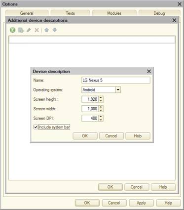
Fig. 783. Device description
In the Device description form, the parameters of the device being added are set:
-
Name. How the device will be displayed in the list.
-
Operating system. Allows you to specify the mobile operating system of your device: iOS, Android, or Windows Runtime.
-
Screen height, Screen width. Indicates the screen resolution of the mobile device for default device orientation.
-
Screen DPI. Indicates the pixel density on the device.
-
Use on-screen buttons. It is used in the preview panel for a more accurate device display.
39.2.8. Help
The tab is used to set up the display type of various help information.
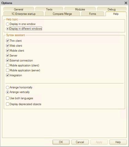
Fig. 784. Help information display settings
Help info can be displayed in one window or split into several independent windows (Display in one window/Display in different windows parameters).
The Syntax Assistant can be arranged horizontally or vertically (Arrange horizontally/Arrange vertically parameters) and use two languages for terms (Use both languages parameter).
The filter of displaying the contents tree and Syntax Assistant index can be set up by object availability for a specific 1C:Enterprise start mode. For example, Syntax Assistant sections can be displayed only for objects available in thin client.
Display deprecated objects checkbox is applied when it is necessary to display the deprecated objects in the Syntax Assistant objects tree. In this case, "object" means any configuration object property, function, procedure, object, and so on. "Deprecated object" means that the object cannot yet be applied or is already not recommended to be used in this compatibility mode. Let us explain the said by examples:
-
StrTemplate() method was added to the platform in version 8.3.6 but this method is not accessible in the mode of compatibility with version 8.3.5. It means that if the Display deprecated objects checkbox is not checked and the configuration compatibility mode is set to Version 8.3.5 (and any preceding version), the StrTemplate() method will not be displayed in the Syntax Assist tree.
-
BackgroundJob.WaitForCompletion() method is announced outdated in the platform of version 8.3.13. It means that if the configuration compatibility mode is set in the value Version 8.3.14 (and subsequent), this method will not be displayed in the Syntax Assist objects tree.
The Syntax Assist tree is rebuilt when the configuration compatibility mode is changed.
This tab can be accessed by using the command bar button in the Syntax Assistant.
39.3. Using calculator
Operations with calculator are described in Calculator section in 1C:Enterprise 8.3 documentation. User Manual.
39.4. Calendar
For description of calendar features, see the Calendar section in 1C:Enterprise 8.3 documentation. User Manual.
39.5. Text templates
You can use Designer to save frequently used text fragments and perform the fast insert operation of cashed fragments in an edited text document or a module.
Text fragment is assigned a conditional combination of characters. That is, a short fragment name called a template. If auto-substitution mode is enabled in Designer parameters, required text fragment is inserted automatically in editor when inputting a template.
Note. IMPORTANT. Auto-substitution mode is enabled separately for modules and text on different tabs of Designer parameters settings.
39.5.1. Template list maintenance
Templates are stored in template files. You can select standard templates shipped with 1C:Enterprise and user templates generated by the user. Standard templates are stored in the bin directory of the installation directory for a particular 1C:Enterprise version. User templates can be stored at any location on the hard drive. The list of attached templates is saved for a 1C:Enterprise language option. You can generate different attached templates sets for different 1C:Enterprise language versions. Standard templates are provided for both 1C:Enterprise language options.
Templates are configured in the Text templates window in a mode that can be called from Service – Text templates.
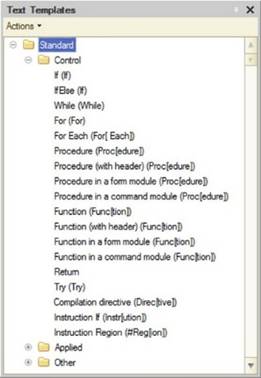
Fig. 785. Text templates
To manage templates, select Actions – Template settings in the Text templates window. The Templates settings is displayed.
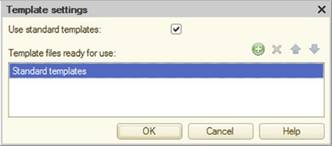
Fig. 786. Template setting
To add standard templates, select the Use standard templates checkbox. Clearing this checkbox disables using of standard templates. Each 1C:Enterprise version uses its own set of standard templates. In addition to standard files, you can attach user templates. To do this, click the Add button on the tools panel of Template settings and select the required template files.
Note. Tip. It is recommended to store user templates in a directory different from the 1C:Enterprise installation directory. For example, you can store templates in a specific subdirectory of the My documents directory.
To rearrange files within the list, use the Move up and Move down buttons.
To delete an unwanted template, select it in the file list and click the Delete button.
39.5.2. Editing a template
To edit an existing template file, use the Actions – Change item. The template editing window containing templates located in the file will be displayed.
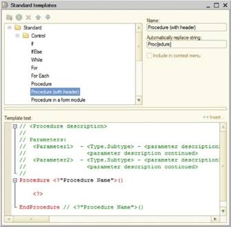
Fig. 787. Template editor
Note. IMPORTANT. Standard templates editing is unavailable. They can only be viewed in the template editor.
In the Name attribute, the template name is displayed as it is shown in the list of templates. In the Automatically replace string attribute, the string sequence is specified, after typing it, Designer allows you to replace it with a template. Replacement is initiated by pressing the Spacebar or Enter key.
Also, when a string is typed, a tooltip containing template text is displayed on the screen as shown on the figure below.
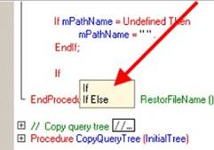
Fig. 788. Using templates
The template editing window contains a tools panel that can be used to create template groups and separate templates, delete unwanted templates and arrange the list. The tree of templates is located in the left part of the window. In the right part, the template group name and the template itself are edited.
For convenience, templates can be grouped into folders. To create a group, use the Add folder command from the context menu or press the appropriate button on the tools panel. Enter a group name in the Name attribute.
To create a template, select a group where it will be located and use the Add command from the context menu or press the appropriate button on the tools panel. Specify the template name in the Name attribute (this name is used to select a template for inserting into edited text). In the Automatically replace string field, you need to specify the initial part of the string and when it is typed, it will be replaced with template text in a text document window (if automatic substitution is on). To use automatic substitution, press Enter or Spacebar key, after entering a sequence of characters. Use the Template text multiline field to enter text that will replace the text specified in the Automatically replace string field or to be saved in document text when a template is selected.
Select the Include in context menu checkbox to make a template available for interactive selection.
A template for insertion in text (module) can be selected from the list of templates in the context menu. Templates are placed in the list if the Include in context menu checkbox is selected.
39.5.2.1. Template controls
Custom query
Description:
Is used to enter any text. When using this template, a dialog box for inputting context-dependent template part is displayed.Syntax:
Parameters:
<Tooltip>
Explanatory label text.
Cursor positioning
Description:
The construct is used to position the cursor to the indicated location after inserting template text.Syntax:
Specific Query
Description:
The construct is used to enter configuration objects, predefined items, and other data.Syntax:
Parameters:
<Tooltip>
Explanatory text in the entry query.
<Keyword>
Type of query.
<Parameter1>...
Query parameters.
Descriptions of specific queries are listed in the following table:
| English option | Description |
|---|---|
| BusinessProcess | Selecting a business process type |
| OptionChoice <Tooltip 1>, <String to insert 1>, …, <Tooltip N>, <String to insert N> | When using this template, a list of strings for selection is displayed. Each string in the list consists of a tooltip and insertion text. Example: "Tooltip 1" – parameter describing the text of the first string in the list "String to insert 1" – parameter or text that will be inserted with selecting the first string |
| TypeChoice | Type selection |
| Document | Document type selection |
| DocumentJournal | Document journal type selection |
| Task | Task type selection |
| EnumValue | Enumeration value selection |
| UserName | Username entry |
| TypeDescriptionConstructor | Type description wizard |
| UserFullName | Full username entry |
| ConfigurationStorageUserName | Entry of full configuration repository username |
| Constant | Constant selection |
| FilterCriterion | Filter criterion selection |
| DataProcessor | Data processor selection |
| Report | Report selection |
| Recalculation | Recalculation selection |
| Enum | Enumeration selection |
| ChartOfCalculationTypes | Chart of calculation types selection |
| ChartOfCharacteristicTypes | Chart of characteristic types selection |
| ExchangePlan | Exchange plan selection |
| ChartOfAccounts | Chart of accounts selection |
| ChartOfCalculationTypesPredefinedData | Selection of predefined data for a chart of calculation types. First, a chart of calculation types is selected and then predefined data value |
| ChartOfCharacteristicTypesPredefinedData | Selection of predefined data for a chart of characteristic types. First, a chart of characteristic types is selected and then predefined data value |
| ChartOfAccountsPredefinedData | Selection of predefined data for a chart of accounts. First, a chart of accounts is selected and then predefined data value |
| MDObjectsSubset | Metadata objects selection. When creating a template, a dialog box opens where you need to select types of metadata objects. When selecting a template, a selection dialog box is displayed, containing all metadata objects of the specified types |
| Seq | Sequence selection |
| AccountingRegister | Accounting register selection |
| AccumulationRegister | Accumulation register selection |
| CalculationRegister | Calculation register selection |
| InformationRegister | Information register selection |
| Catalog | Catalog selection |
| CatalogPredefinedData | Selection of predefined data from the catalog. First, a catalog is selected and then the predefined data value |
| QueryText | The query text is entered using the query wizard |
| DateTime, <Format string> | Entry of the current date in the format specified in the <Format string> parameter |
| FormatString | The format string text is entered using the format string wizard |
39.5.2.2. Template text editor
Structurally, a template can consist of a static (unchangeable) part and a dynamic part, which content is context-dependent and cannot be specified in advance. For example, the If operator of the 1C:Enterprise language has the following structure:
If<?"Condition 1"> Then
ElseIf <?"Condition 2"> Then
EndIf;
<?"Condition...">These are context-dependent template parts.
For versatility of template use, the control directive insertion mechanism is applied. Control directives are inserted into the template text. Control directives are character sequences that initiate execution of some actions when inserting the replacing template text. For example, control directives allow you to request information from the user and to add this information to the text to be inserted.
Control directives can be inserted into the template manually, or interactively, using a specific query.
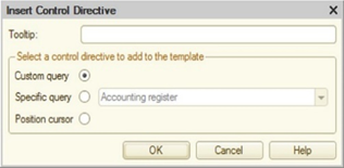
Fig. 789. Control directive insertion
You need to position the cursor in the template area with a variable part and click <->Insert... The Insert control directive dialog box is displayed.
In the Tooltip attribute, user specifies a text line displayed as an explanation to an action performed when a context-dependent part of template is requested. Since a template can contain several control directives that can be entered in a sequence, this text explains the performed actions and the location of the variable part.
Radio button group can be used to select the type of a control directive for insertion into the template.
A custom query is used to enter any text. A control directive of <?"Tooltip text"> type will appear in the template text.
The Custom query control directive is used as follows. If the text to be replaced contains a <?"Tooltip text"> directive, a request with tooltip text and text input field is displayed before the replacement text is inserted. In the input field, you can specify the text to be inserted in the replacement text instead of <?"Tooltip text"> directive. There could be several Custom query type directives in the replacement text and some directives can have the same tooltip text. When inserting a replacement text, a specific text request is provided for each directive. There will be one common query for all identical directives and the text entered in the query will replace all identical directives.
Specific query is used to select configuration objects. To place a type selection of a configuration object into the control directive template using the Insert control directive window, you need to enter the query name in the Tooltip field and select a directive from the list (selection of configuration object, predefined configuration object item or an appropriate directive), for example, Catalog.
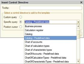
Fig. 790. Specific query
When using this template, a list of possible configuration objects is displayed. The name of a selected object is placed instead of the entered text. Position of the selected string is stored and the list will be positioned on this string when selecting this template again.
The possible values of a specific query include the switch. We will additionally describe it. When a template with this type of a query is formed and OK is clicked, the window of possible values formation list is displayed.
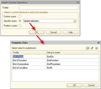
Fig. 791. Data to select
The Tooltip column is used to enter text that will be displayed in the selection list when this template is used. The Insertion string column is used to enter text that will be placed into the text document.
The list can only be edited in the template text. When re-calling the insert directive, a new directive will be added.
After clicking OK, a control directive is inserted into the template text.
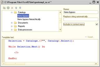
Fig. 792. Template with a control directive
In the template tree (or during automatic substitution), select this template.
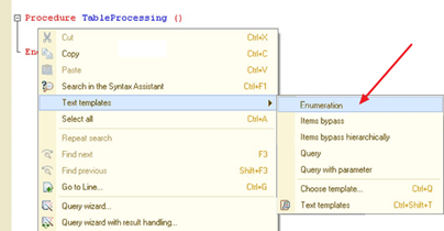
Fig. 793. Context menu
In this case, a catalog type selection query is displayed.
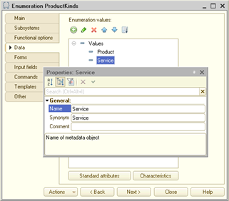
Fig. 794. Enumeration selection
As a result of a selection, the following text is generated:
PredefinedValue("Enumeration.ProductTypes.Product")Position cursor. Is used to position the cursor in the indicated location after inserting template text. The <?> type directive is inserted in the replacement template text. It defines where the cursor must be positioned when entering the replacement text. If there are several directives of this type in the replacement text, the cursor is positioned in the first in order <?> directive place.
When writing a template text, the use of multiple control directives as well as the use of existing templates is allowed.
39.6. Syntax Assistant
39.6.1. General information
Syntax Assistant is a tool that facilitates module development. The main task of the Syntax Assistant is to provide swift tooltips on 1C:Enterprise language to the specialist configuring 1C:Enterprise.
To call the Syntax Assistant, use the Help – Syntax Assistant item.
The Syntax Assistant window is divided into two parts. Window division can be performed vertically or horizontally.
The selected 1C:Enterprise section details are displayed in the bottom (or right) part. The contents of the upper (or left) part are defined by the selected tab.
The window contains three tabs: Content, Index, and Search. The first tab contains a hierarchical list of 1C:Enterprise language items: operators, control directives, procedures and functions, system constants, and so on. The second and third tabs are used for search by names of 1C:Enterprise language items and for custom search by description text correspondingly.
If horizontal arrangement is selected for the Syntax Assistant, tabs on the command bar are replaced with buttons that have the same names.
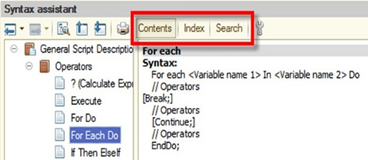
Fig. 795. Horizontal arrangement
The filter of displaying the contents tree and Syntax Assistant index can be set up by object availability for a specific 1C:Enterprise start mode.
39.6.2. Syntax Assistant setting
To find out how to set up Syntax Assistant, see Help.
Command bar buttons of the Syntax Assistant are described on fig. 796.
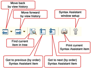
Fig. 796. Description of command bar buttons
39.6.3. "Content" tab of Syntax Assistant
For convenience, all 1C:Enterprise language items are grouped into thematic sections, presented in the form of tree branches, that is displayed in the upper part of the Syntax Assistant window.
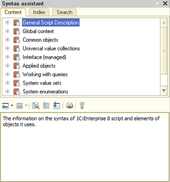
Fig. 797. Syntax Assistant window
Operating methods in the Syntax Assistant window are standard for hierarchical data that is presented as a tree. To quickly expand a branch, press "+", "-" or "" on the numeric keypad. "+" expands one level of the branch, "-" collapses a level, and "" expands all sub-branches of the current branch.
To get description, select the name of a 1C:Enterprise language item in the upper part of the Syntax Assistant window. Item description will be displayed in the lower part of the window. Description can contain links to descriptions of the referenced 1C:Enterprise language items.
The window contains a toolbar that can be used to view the history of previously selected descriptions.
To display the location of an item, description of which is currently displayed in the lower part of the window, in 1C:Enterprise language items structure, click the Find current element in tree button in the toolbar.
39.6.4. Copying 1C:Enterprise language items
The Syntax Assistant has a function that allows you to copy the selected 1C:Enterprise language item to the text editor.
To make a copy, select the name of the desired language item in the tree-type list and use the clipboard. 1C:Enterprise language item instance will be moved to the cursor position in the text editor window.
Instead of using the clipboard for copying, you can also drag and drop instances of 1C:Enterprise items: just drag an item from the Syntax Assistant window to the text editor window.
39.6.5. Searching in Syntax Assistant
Searching in Syntax Assistant can be performed by 1C:Enterprise language item name and by arbitrary description text.
A search by 1C:Enterprise language item name is performed in the Index tab of the Syntax Assistant window. The upper part contains a field to input the required 1C:Enterprise item name and a full list of all item names.
During the name input, the program performs a context search. When searching, with each typed character a transition is made to the first name on the list that begins with the entered character.
To call the context search mode, select the Search item in Syntax Assistant from the context menu of text editor. This will display the Syntax Assistant window, that is opened on the Index tab.
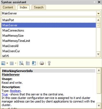
Fig. 798. Syntax Assistant index
If the found (specified) item is used in several objects, the Select section window, that contains a list of entries for the selected item, will open.
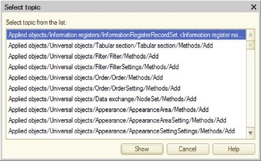
Fig. 799. Select section
Now, if you click Show, the description of the found 1C:Enterprise item selected in the window of entries will be displayed in the Syntax Assistant window.
Note. Tip. If the Select section window contains a lot of lines (see fig. 799), you can press the Ctrl + F key combination and enter the name of the searched object in the search dialog box. This will speed up the search for the required section.
You can search for 1C:Enterprise language item description in the Syntax Assistant while editing a module. To perform a search, position the cursor over the 1C:Enterprise language item for which you want to get a description or select a text block and press Ctrl + F1 key combination. The result of the search with the help of Ctrl + F1 key combination does not depend on the Display deprecated objects checkbox status. It is assumed that the help info is obtained conditionally with the help of the method which is already in the configuration source text.
If the word, on which the cursor is positioned or the selected text block is a 1C:Enterprise language item described in the Syntax Assistant, the Syntax Assistant window containing the description of this item will be immediately displayed.
If a 1C:Enterprise language item is described in several thematic sections of the Syntax Assistant, the Select section window will open first to select the necessary thematic section.
If the selected word or text block is not a 1C:Enterprise language item, the context search window will open in the Syntax Assistant when you press Ctrl + F1. key combination.
The performed search is stored in a list that can be called in the name input field.
To view a section, select it from the list and press the Enter key. Description of the selected section will be shown in the lower field.
TheSearch tab of the Syntax Assistant window is used to search using an arbitrary description text. The upper part contains a search string input field and a field with a list of founded 1C:Enterprise language items descriptions.
To begin the search, start typing text. While typing, the program searches for sections where the entered text is found. You can use any input register, text words are considered wholly (unless the "*" operator is used), with morphology also considered. You can use search operators.
While typing, the program swiftly displays a list of these sections.
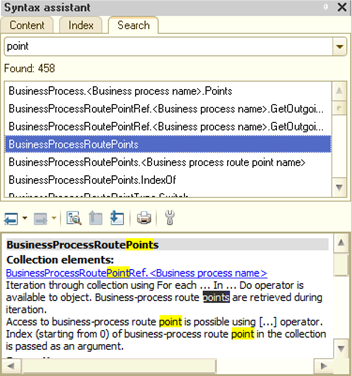
Fig. 800. Searching in Syntax Assistant
When you open a topic, the help system highlights the first occurrence of the search string in that topic.
To view a topic, select it in the list and press Enter. Description of the selected section will be shown in the lower field.
When the section containing description of the 1C:Enterprise language item is found and the Syntax Assistant window is open, use the Find current element in the tree button of the command bar to search for the section in the description tree.
If you selected several pages while viewing, you can use the Go forward and Go back commands to return to previously viewed pages.
39.6.6. Using methodological materials
When viewing a Syntax Assistant article, there is a feature to go to various methodological materials available on the 1C company web resources. For this purpose, there is a Methodical materials hyperlink at the bottom part of the Syntax Assistant article.
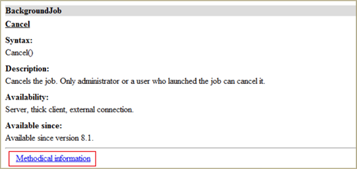
Fig. 801. Methodical information
Clicking this link will open a web browser, which will display an appropriate page with links to additional materials on the studied Syntax Assistant article. To navigate through the links an authorization on the relevant site might be required.
In Windows OS, the link will be opened in Microsoft Internet Explorer and in Linux OS, the web browser used will depend on the system settings.
39.6.7. Versions details
The information on the versions associated with the displayed object is displayed in the bottom section of the Syntax Assist window which displays the information on the property, function, procedure, and so on.
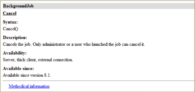
Fig. 802. Versions details
Note. Note. The information on the recommended replacements is displayed for the Syntax Assist objects, which were outdated in version 8.3.14 and subsequent versions. No such information is provided for the objects announced outdated in the preceding versions.
The following set of information is displayed:
-
The platform version as of which release the object was implemented. In this case, if the object implementation version precedes version 8.3.1 then only the first two numbers are displayed as the version details, for example, Accessible from version 8.1. If an object was implemented in version 8.3.1 (and subsequent versions) then more complete details are displayed, for example, Accessible from version 8.3.6. If an object was implemented considering the compatibility mode, this information will be displayed in Syntax Assistant as well: Accessible from version 8.3.6 (in compatibility mode with version 8.3.6 and later).
-
The platform version as of which release the object was announced outdated. If there are recommended replacements for the outdated object then the link to the recommended objects will be displayed in the Syntax Assist window as well.
-
The platform version as of which release the object description was considerably amended. The term "considerable amendment" means any change in the information describing the object functioning. For example, if a list of accessibility is changed for the object, it is a considerable amendment. If any orthographic mistakes are corrected, it is an inconsiderable amendment. The information on such change will be represented by the Description is edited in version 8.3.13 text.
The current configuration compatibility mode determines which platform objects can and cannot be used in this configuration. Syntax Assistant simplifies the decision-making: whether this object can be used in this compatibility mode or not. If the compatibility mode prevents the object use then the reason is displayed in red in the top section of the object details, before the syntax description. There can be two reasons:
-
Object is not accessible yet. It means that the compatibility mode is set to the value for which the desired platform object is not implemented yet.
-
Object is not accessible already. It means that the used object is announced outdated and its use is not recommended. Despite the fact that the deprecated objects remain functional to keep the compatibility (as a rule), the use of replacements is recommended.
39.7. Comparing files
You can compare any two files. To do this, select File – Compare files item. This opens the file selection dialog box.
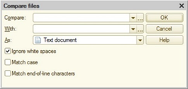
Fig. 803. Comparing files
In the Compare and To fields, specify the names of the files to be compared. File names can be entered manually, selected from the drop-down list or by clicking the (…) selection button, call the standard file opening dialog box and select the file in this dialog box. You can specify any type of source file in the File Type field of the dialog box.
In the As field, specify the file comparison method. You can compare text and spreadsheet documents, external data processor. You can also use the binary comparison, where the files are compared on a binary level. If you choose binary comparison, the comparison returns a message whether the files are identical or different.
If files of different types are specified in the Compare and To fields, the selected files will be interpreted by comparison to the type specified in the As field. Then a comparison is performed and comparison results are displayed.
Click OK to start comparison.
If you select Text document as a comparison type, the selected files are interpreted as text documents for comparison purposes, although the Compare and To fields can contain nontext files. They can have extensions that are not suitable for text files. If one or both of the specified files cannot be interpreted as a text file, a binary comparison is conducted.
39.7.1. Comparing external data processors
When comparing external data processors, a standard procedure of external data processor comparison is conducted (for details, see Comparing and merging external data processors (reports)).
Selecting the Match by object names checkbox will allow matching objects firstly by names and then by internal IDs. If the checkbox is cleared, matching is done by internal IDs.
39.8. Built-in help application
Help content can be used to get information on the 1C:Enterprise operations and on specific objects and modes. You can call it at any time by selecting Help item or by pressing the F1 key. This will open the help information section that corresponds to the mode in which the user is currently operating.
The Contents menu item and the Shift + F1 key combination allows you to access the overall contents of help information where you can get information on operations in Designer mode.
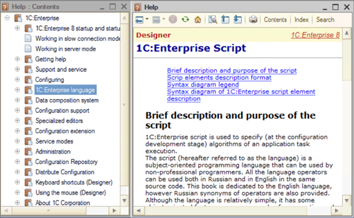
Fig. 804. Help content
Help content contains a description of configuration sections, 1C:Enterprise language, and additional help information.
The toolbar used for navigation and information searching is located in the upper part of the help content window. The help content is displayed below the toolbar.
Appendix 1. URL formats
1.1. URL format description
1.1.1. General information and link types
In this appendix, you can read about URL formats used in 1C:Enterprise. URLs can be external or internal. External links are used outside 1C:Enterprise, while internal links are used internally and can also be added to favorites list and operation history.
A URL consists of several parts:
-
Infobase host address. Describes the infobase location relative to the client application. To receive this part of the link, use the GetInfoBaseURL() method.
-
Internal link. Describes the location of requested information within the infobase.
-
Link parameters. Describes the parameters that specify URL behavior. Parameters might be specified not for all URLs.
There are several types of Internal links:
-
Infobase object.
-
Infobase object attribute.
-
Infobase object table attribute.
-
Infobase register record attribute.
-
Infobase register record.
-
Report.
-
Data processor.
-
Section.
-
Section command.
-
Temporary storage.
-
Collaboration system conversation.
External link is created by adding an internal link to the host address. If a link opens a form or performs navigation in the main window, the following rule is used to create an external link:
<infobase
host address>#<internal link>? <link parameters>These links are references to an infobase object, report, data processor, section and section commands links.
If a link is a resource, an external link is generated as follows:
<infobase
host address>/<internal link>? <link parameters>These links are references to attributes of infobase object or information register record or temporary storage links.
1.1.2. URL parameters
URL parameters are specified in a URL after a question mark "?" that separates a URL and the list of parameters. If a URL has several parameters, they are separated with an ampersand "&". A parameter consists of a parameter name and a parameter value that are separated with an equality sign "=". If a parameter value is an array, then array element values are comma-separated. If a parameter value is a link to an object of a certain type, a type name must be written before the link value. A type name and a link value are colon-separated, for example: DocumentRef.SalesInvoice:a9b000055d49b45e11db8c4c9d5c4223.
URL in the following format: e1cib/data/Catalog.Goods?ref=949b0050569f397311e8bb08fb974c0a represents:
-
Internal URL as it does not contain an infobase address.
-
Link to the Goods catalog item.
-
Link has a parameter with the ref name and the 949b0050569f397311e8bb08fb974c0a value.
If a string contains several parameters with the same name, only the first parameter (moving from left to right) is used. Unknown parameters in URLs are ignored.
Note. Tip. If multiple clients are operating with the infobase, it is not recommended to save external links to infobase objects because this may lead to the inoperability of the link created in one client in another client. For example, an external link created in the web client can be unavailable in thin client "directly" attached to 1C:Enterprise server. It is recommended to save internal links.
A URL allows you to pass the list of parameters to an object to be opened. In this case, use the extdata parameter of a URL. The parameter value is a value ID in the storage with external data of URLs. The way the value received from the storage is interpreted depends on the object that is opened using a URL.
1.1.3. Host address format
Depending on the infobase type, the string describing host address can look differently.
Infobase file mode
If a UNC format is used to define the database file path, host address looks as follows:
e1c:/file/<UNC-path>Example:
// File infobase path
//dbsrvr/bases/mybase
// Host address
e1c:/file/dbsrvr/bases/mybaseIf the file path includes a hard drive letter, host address looks as follows:
e1c:/filev/<Hard drive letter>/Example:
// File infobase path
s:/bases/mybase
// Host address
e1c:/filev/s/bases/mybaseClient/server mode of infobase
For client/server mode of the infobase, link looks as follows:
e1c://server/<server name>/<infobase
name>Example:
// Infobase connection string
srvsr="srv1C";ref="mybase"
// Host address
e1c://server/srv1C/mybaseWhen operating via web server (thin client or web client)
If a web server is used to operate with the infobase, link looks as follows:
http://<host address>/<infobase path>
https://<host address>/<infobase path>Example:
// Infobase connection string
http://localhost/mybase
// Host address
http://localhost/mybaseSeparator values
Regardless of the infobase type, the host address can contain separator values. Add separator values if the reference is generated in the separated infobase. To specify separators, use the Z reference parameter after "?":
<host address>/<infobase
name>[?Z=<separator values>]For the thin client, in the URL, specify all separator values used in the current session. For the web client and the thin client running on the web server, in the URL, specify values for separators for which the checkbox that indicates that a separator value must be set in the infobase address was not selected when publishing on the web server.
See also:
-
Specifying separators.
-
Specifying separators in the default.vrd file.
1.2. Internal links
1.2.1. General information
Common internal link format looks as follows:
<affiliation>/<type>/<path>[?<parameter>=<parameter
value>[&<parameter>=<parameter value>]]Internal link affiliation describes where the object identified by this link is located:
-
e1cib. Information is stored in the infobase.
-
e1ccs. Information is stored on the collaboration system server.
A detailed description of type-dependent link is given below.
1.2.2. Infobase objects links
1.2.2.1. Infobase object link
Format:
e1cib/data/<metadata path>?ref= <link ID>Where:
-
Metadata path is a linked object type, for example, Document.GoodsConsumption.
-
Link ID is an infobase object UUID.
1.2.2.2. Infobase object attribute link
Format:
e1cib/data/<metadata path>.<attribute
name>?ref=<link ID>Where:
-
Metadata path is a linked object type, for example, Document.GoodsConsumption.
-
Attribute name is an infobase object attribute name.
-
Link ID is an infobase object UUID.
1.2.2.3. Link to the infobase object table attribute
Format:
e1cib/data/<metadata path>.<table
name>.<attribute name>?ref=<link ID>&index=<table row
index>Where:
-
Metadata path is a linked object type, for example, Document.GoodsConsumption.
-
Table name is a metadata object table name, for example, Goods.
-
Attribute name is a name of the infobase object table attribute.
-
Link ID is an infobase object UUID.
-
Table row index is a table row index.
1.2.2.4. Infobase register record link
Format:
e1cib/data/<metadata path>?<key field
name>=<value>[&<key field name>=<value>]Where:
-
Metadata path is a linked object type, for example, InformationRegister.ProductBalance.
-
Key field name is a register dimension name. The Period dimension is added to periodic registers.
-
Value is an internal filter value presentation. Filter value is coded according to section 2.2. URL Character Encoding Issues of RFC 1738 standard (https://datatracker.ietf.org/doc/html/rfc1738) using the "%" character and two hexadecimal characters.
1.2.2.5. Link to the infobase register record attribute
Format:
e1cib/data/<metadata path>.<attribute
name>?<key field name>=<value>[&<key field
name>=<value>]Where:
-
Metadata path is a linked object type, for example, InformationRegister.ProductBalance.
-
Attribute name is a register record attribute name.
-
Key field name is a register dimension name. The Period dimension is added to periodic registers.
-
Value is an internal filter value presentation. Filter value is coded according to section 2.2. URL Character Encoding Issues of RFC 1738 standard (https://datatracker.ietf.org/doc/html/rfc1738) using the "%" character and two hexadecimal characters.
1.2.2.6. Report link
Format:
e1cib/app/<metadata path>?vrn=<option
name>&stngs=<storage key>Where:
-
Metadata path is a linked object type, for example, Report.ProductBalance.
-
vrn. Allows you to specify a report option key that is required when opening a report. The parameter value is set as a value of the VariantKey parameter of a report form to be opened. Optional parameter.
-
stngs. Allows you to specify a storage key of external URL data. A value in the storage must be specified in the data composition settings that are set as a value of the Variant parameter of a report form to be opened. Optional parameter.
If a URL contains the vrn and stngs parameters at the same time, the vrn parameter is ignored and only the stngs parameter is used to generate a report.
1.2.2.7. Data processor link
Format:
e1cib/app/<metadata path>Where:
- Metadata path is a linked object type, for example, DataProcessor.OrderGeneration.
1.2.2.8. Section link
Format:
e1cib/navigationpoint/<section
name>Where:
- Section name is a linked first-level subsystem name, for example GoodsSales.
1.2.2.9. Link to the navigation point created by standard command
Format:
e1cib/navigationpoint/<section
name>/<command name>Where:
-
Section name is a linked first-level subsystem name, for example, GoodsSales.
-
Command name is a command name, for example, Catalog.Goods.OpenList.
1.2.2.10. Temporary storage link
Format:
e1cib/tempstorage/<temporary value ID>Where:
- Temporary value ID is a temporary value ID.
1.2.2.11. Link to the external data source table record
Format:
e1cib/data/<metadata
path>?<key field name>=<value>[&<key field
name>=<value>]Where:
-
Metadata path describes external data source table, for example, ExternalDataSource.Receipts.Table.CheckHeaders.
-
Key field name is a table key field name of the external data source.
-
Value is an internal filter value presentation. Filter value is coded according to section 2.2. URL Character Encoding Issues of RFC 1738 standard (https://datatracker.ietf.org/doc/html/rfc1738) using the "%" character and two hexadecimal characters.
1.2.2.12. Links to commands of the global command interface
Format:
e1cib/command/<command
name>?cmdprm=<command parameter>&extdata=<address>Where:
-
Command name is a command name:
-
Standard command: Catalog.Goods.Create.
-
Common command: CommonCommand.ObjectSearch.
-
Command: Catalog.Goods.Command.PrintBarcode.
-
-
cmdprm. Passes the command parameter. If the parameter can have several values (an array), these values must be comma-separated. If a value has a union type, specify the value type first and then the link value after a colon ":". A command for printing several documents may look as follows:
e1cib/command/CommonCommand.PrintInvoice?cmdprm=DocumentRef.SalesInvoice:a9b000055d49b45e11db8c4c9d5c4223,DocumentRef.SalesInvoice:e440000a5d49b45b33de8c4c9d5c4223The parameter is optional.
- exdata. Specifies an address in the external URL data storage. A structure received from the storage is set as the value of the Parameters property of the CommandExecuteParameters command handler parameter. The parameter is optional.
1.2.2.13. Dynamic list links
Format:
e1cib/list/<list name>?stngs=<storage
key>Where:
-
List name is a name of the list to open, for example Catalog.Goods and Documents.GoodsConsumption.
-
stngs. Allows you to specify a storage key of external URL data. A value in the storage must be specified in the dynamic list table settings (the DynamicListTableSettings type) that contain fixed settings (the FixedSettings property), user settings (the UserSettings property), representation mode for hierarchical lists (the TableRepresentation property), and the current row (the CurrentRow property).
If the value of the DynamicListTableSettings.CurrentRow property is Undefined, the current row in a dynamic list to be opened is set according to the following dynamic list properties: RestoreCurrentRow and InitialListView.
Optional parameter.
1.2.2.14. Home page links
Format:
e1cib/navigationpoint/desktopIn version 8.3.2 or later compatibility mode.
Format:
e1cib/navigationpoint/startpageIn versions earlier than 8.3.2 compatibility mode.
1.2.3. Collaboration system object links
1.2.3.1. Conversation link
Format:
e1ccs/data/conv?id=<conversation
ID>Where:
- Conversation ID is a collaboration system conversation UUID.
1.2.3.2. Message link
Format:
e1ccs/data/msg?id=<message
ID>Where:
- Message ID is a collaboration system message UUID.
The obtainment of links to the service and sent messages is not supported.
Appendix 2. Rules of generating standard command texts and automatic form headers
To predefine (or specify) objects presentation in an interface, a set of properties is implemented in metadata properties.
| Object | Extended presentation | Object presentation (records for a register): | Extended object presentation (records for a register) | List presentation | Extended list presentation | Description | Picture |
|---|---|---|---|---|---|---|---|
| Subsystems | + | + | |||||
| Constants | + | + | |||||
| Exchange plans | + | + | + | + | + | ||
| Filter criteria | + | + | + | ||||
| Common forms | + | + | |||||
| Constants | + | + | |||||
| Catalogs | + | + | + | + | + | ||
| Documents | + | + | + | + | + | ||
| Document journals | + | + | + | ||||
| Enumerations | + | + | + | ||||
| Reports | + | + | |||||
| Data processors | + | + | |||||
| Charts of characteristic types | + | + | + | + | + | ||
| Charts of accounts | + | + | + | + | + | ||
| Charts of calculation types | + | + | + | + | + | ||
| Information registers (subordinate) | + | + | + | ||||
| Information registers (independent) | + | + | + | + | + | ||
| Accumulation registers | + | + | + | ||||
| Accounting registers | + | + | + | ||||
| Calculation Registers | + | + | + | ||||
| Business processes | + | + | + | + | + | ||
| Tasks | + | + | + | + | + |
When generating presentation of standard commands (and their tooltips), the application uses the following rules (Property1 à Property2 means that if Property1 is not specified, Property2 is used instead):
-
List opening:
-
Command presentation: List presentation.
-
Command tooltip: Note à Extended list presentation à List presentation.
-
-
New object (record) creation:
-
Command presentation: Object presentation: create or Record presentation: create.
-
Command tooltip: Extended object presentation (Extended record presentation) à Object presentation (Record presentation).
-
-
New group creation:
-
Command presentation: List presentation: create a group.
-
Command tooltip: Extended list presentation à List presentation.
-
-
Navigation to any subordinate list (command of the Go to form navigation panel group):
-
Command presentation: List presentation.
-
Command tooltip: Note à Extended list presentation à List presentation.
-
-
Generate:
-
Command presentation: Object presentation: generate.
-
Command tooltip: Extended object presentation à Object presentation.
-
-
Report or data processor opening:
-
Command presentation: report or data processor presentation.
-
Command tooltip: Note à Extended presentation.
-
-
Common form opening:
-
Command presentation: common form presentation.
-
Command tooltip: Note à Extended presentation.
-
-
Constant editing form opening:
-
Command presentation: constant presentation.
-
Command tooltip: Note à Extended presentation.
-
-
Navigation to subsystem (in sections panel):
-
Command presentation: subsystem presentation.
-
Graphical presentation: Picture à standard picture of sections panel section.
-
Command tooltip: Note.
-
Note. Note. If none of the used (in tooltip and/or presentation generation) properties is specified, text presentation of metadata object is used as it is returned by the Presentation() method.
When you place a command in the actions panel or the form command bar, the following rule is applied: a command group name (preceded by a colon ":") is removed from a command presentation text if this combination completes the command presentation. For example, the standard command to create an item of the Goods catalog that looks as Goods: create will look as Goods in the actions panel. If you create a command presented as My command: generate and place it into the standard Generate group of the form command bar, then the command presentation will be My command. At the same time, if you place this command into the Print group (that is created by the developer) of the form command bar, the command presentation will remain as My command: generate.
Properties associated with objects presentation (see table above) are also used in form headers generation if the Automatic header form property is set to True. In this case, the form header combines the Header form property and an automatically generated header. If this property is set to False, the Header form property is used as a header without any changes.
When automatically generating a form header, 1C:Enterprise follows the following rules:
-
List form header: Extended list presentation à List presentation.
-
Headers for catalog form, chart of accounts, chart of calculation types, exchange plan, chart of characteristic types, tasks:
-
Existing item: text presentation of an object (Extended object presentation à Object presentation). For example:
-
Zinoviev Anton (Employee).
-
70.1 (Account).
-
-
New item: Extended object presentation (Create) à Object presentation (Create).
-
-
Document or business process form header:
-
Existing item: text presentation of an object. For example:
- Invoice No. 12001 dated 05/12/2008 16:15:32.
-
New item: Extended object presentation (Create) à Object presentation (Create).
-
-
Header of the information register record form:
-
Existing record: Extended record presentation à Record presentation.
-
New record: Extended record presentation (Create) à Record presentation (Create).
-
-
Group form header of a catalog or a chart of characteristic types:
-
Existing group: text presentation of an object (Extended list presentation à List presentation).
-
New group: Extended list presentation (Create a group) à List presentation (Create a group).
-
-
Report or data processor form header: Extended presentation.
Note. Note. If none of the properties used in name generation is specified, text presentation of metadata object is used as it is returned by the Presentation() method.
Appendix 3. List of automatically saved settings
The appendix describes settings automatically stored in 1C:Enterprise storage by the platform.
3.1. Storage: report options
Setup: report options
- Object key: full report name.
Example of an object key:
Report.Sales- Setting key: option text ID.
Example of a setting key:
SalesByRegion- Saved value type: DataCompositionSettings.
3.2. Storage: report settings
Setup: report settings
- Object key: text line consisting of a full report name, "/" symbol and option key.
Example of an object key:
Report.Sales/SalesByRegion- Setting key: text ID of a setting.
Example of a setting key:
MyClients- Saved value type: DataCompositionUserSettings.
3.3. Storage: form data
Setup: form field values
- Object key: full form name.
Example of an object key:
Processing.DataExport.Form.DefaultForm- Setting key: text ID of saved values.
Example of a setting key:
ExportToSberbank- Saved value type: Map. Map key is a text path to the saved data attribute and its value is the attribute value.
3.4. Storage: dynamic list settings
Setting: dynamic list settings
- Object key is a line value consisting of full form name and the DynamicList attribute type name.
Example of an object key:
Document.GoodsArrival.Form.ListForm.List-
Setting key: text ID of saved values.
-
Saved value type: DataCompositionUserSettings.
3.5. 1C:Enterprise storage
3.5.1. Form settings
Setup: key of the current form field setting
- Object key is a line value consisting of a full form name and the /CurrentDataSettingsKey text.
Example of an object key:
Processing.DataExport.Form.DefaultForm/CurrentDataSettingsKeyIf the PurposeUseKey property is set for a form, an object key is generated as follows: a full form name, a slash "/", a value of the PurposeUseKey property, and the /CurrentDataSettingsKey string.
Example of an object key:
DataProcessor.DataExport.Form.DefaultForm/ForDiscountChargeForm/CurrentDataSettingsKeyIn this example, the PurposeUseKey property is set to ForDiscountChargeForm.
-
Setting key: blank string.
-
Saved value type: any value containing the current setting key.
Setup: form field values on closing
- Object key is a string value consisting of a full form name and the /CurrentData text.
Example of an object key:
DataProcessor.DataExport.Form.DefaultForm/CurrentDataIf the PurposeUseKey property is set for a form, an object key is generated as follows: a full form name, a slash "/", a value of the PurposeUseKey property, and the /CurrentData string.
Example of an object key:
DataProcessor.DataExport.Form.DefaultForm/ForDiscountChargeForm/CurrentDataIn this example, the PurposeUseKey property is set to ForDiscountChargeForm.
-
Setting key: blank string.
-
Saved value type: Map. Map item key is a text path to saved data attribute and its value is the attribute value.
Setup: form display setting
- Object key is a string value consisting of a full form name and the /FormSettings text.
Example of an object key:
DataProcessor.DataExport.Form.DefaultForm/FormSettingsIf the PurposeUseKey property is set for a form (the property value is not empty), an object key is generated as follows: a full form name, a slash "/", a value of the PurposeUseKey property, and the /FormSettings string.
Example of an object key:
DataProcessor.DataExport.Form.DefaultForm/DefaultOption/FormSettingsIn this example, the PurposeUseKey property is set to DefaultOption.
-
Setting key: blank string.
-
Saved value type: FormSettings. Object with no properties and methods.
Setup: form size, size of controls, separator location, conversation panel state (its size, it is open/closed), and table column width
-
Object key is a string value that consists of a full form name (hereinafter referred to as FullFormName) and a text that depends on the compatibility mode:
-
Version 8.3.17 or earlier:
-
Another interface: FullFormName/WindowSettings.
-
Taxi interface: FullFormName/Taxi/WindowSettings.
-
-
Version 8.3.18 or later:
-
Another interface: FullFormName/ThinClientWindowSettings.
-
Taxi interface:
-
Thin client and thick client: FullFormName/Taxi/ThinClientWindowSettings.
-
Web client: FullFormName/Taxi/WebClientWindowSettings.
-
Mobile client: FullFormName/Taxi/MobileClientWindowSettings.
-
Mobile platform: FullFormName/Taxi/MobilePlatformWindowSettings.
-
-
-
Example of an object key:
DataProcessor.DataExport.Form.DefaultForm/ThinClientWindowSettingsIf you operate with a form for which the WindowOptionsKey property is set, an object key includes the key value: <WindowOptionKeyValue>/WindowSettings*.
For example, if the window option key value is DefaultMode, the above example will look as follows:
DataProcessor.DataExport.Form.DefaultForm/DefaultMode/ThinClientWindowSettings-
Setting key: blank string.
-
Saved value type: WindowSettings. Object with no properties and methods.
Every 20 minutes of the client application operation, the / ThinClientWindowSettings and / WebClientWindowSettings settings are saved for all forms whose settings were changed since the last save.
To remove the settings of any form, perform this operation before the first opening of the form in current session.
Setup: search history in a form table
- Object key: Common/TableSearchHistory/<Form name>.<Table name>.
Example of an object key:
Common/TableSearchHistory/Catalog.Goods.Form.ListForm.List-
Setting key: blank string.
-
Saved value type: TableSearchHistory. Object with no properties and methods.
Setup: history of selecting values in the input field of a managed form
-
Object key: ChoiceHistory string value.
-
Setting key: blank string.
-
Stored value type: ChoiceHistorySettings object. Object with no properties and methods.
3.5.2. Report settings
Setup: key of the current report option
- Object key: text line consisting of a full report name and the /CurrentVariantKey string.
Example of an object key:
Report.Sales/CurrentVariantKeyIf thePurposeUseKey property is set for a form, an object key is generated as follows: a full report name, a slash "/", a value of the PurposeUseKey property, and the /CurrentVariantKey string.
Example of an object key:
Report.Sales/ForDiscountChargeForm/CurrentVariantKeyIn this example, the PurposeUseKey property is set to ForDiscountChargeForm.
-
Setting key: blank string.
-
Saved value type: any value that contains the current option key.
Setup: key of the current report setting
- Object key is a string value consisting of a full report name, report option key as a string and the /CurrentUserSettingsKey text.
Example of an object key:
Report.Sales/SalesByRegion/CurrentUserSettingsKeyIf the PurposeUseKey property is set for a form, an object key is generated as follows: a full report name, a slash "/", a report option key as a string, a slash "/", a value of the PurposeUseKey property, and the /CurrentUserSettingsKey string.
Example of an object key:
Report.Sales/SalesByRegion/ForDiscountCalculationForm/CurrentUserSettingsKeyIn this example, the report option key is set to SalesByRegion and the PurposeUseKey property is set to ForDiscountChargeForm.
-
Setting key: blank string.
-
Saved value type: any value that contains the current option key.
Setup: report option settings on report closing or option changing
- Object key is a line value consisting of a full report name, report option key as a string and the /CurrentUserSettings text.
Example of an object key:
Report.Sales/SalesByRegion/CurrentUserSettingsIf the PurposeUseKey property is set for a form, an object key is generated as follows: a full report name, a slash "/", a report option key as a string, a slash "/", a value of the PurposeUseKey property, and the /CurrentUserSettings string.
Example of an object key:
Report.Sales/SalesByRegion/ForDiscountCalculationForm/CurrentUserSettingsIn this example, the report option key is set to SalesByRegion and the PurposeUseKey property is set to ForDiscountChargeForm.
-
Setting key: blank string.
-
Saved value type: DataCompositionUserSettings.
Setup: result reduction width used for report generation
-
Object key is a text string consisting of a full report name and a string depending on the client application:
-
Thin client and thick client: /ResultReductionWidthThinClient.
-
Web client: /ResultReductionWidthWebClient.
-
Mobile client: /ResultReductionWidthMobileClient.
-
Mobile platform: /ResultReductionWidthMobilePlatform.
-
-
Saved value type: Number.
Setup: report result display mode
-
Object key is a text string consisting of a full report name and a string depending on the client application:
-
Version 8.3.17 or earlier:
- Thin client, thick client, and web client: /ResultViewMode.
-
Version 8.3.18 or later:
-
Thin client, thick client, and web client: /ResultViewModeThinAndWebClient.
-
Mobile client: /ResultViewModeMobileClient.
-
Mobile platform: /ResultViewModeMobilePlatform.
-
-
-
Saved value type: the ReportResultViewMode type value.
3.5.3. Dynamic list settings
Setting: dynamic list settings
- Object key is a string value consisting of a full form name, the DynamicList type attribute name and the /CurrentUserSettings text.
Example of an object key:
Document.GoodsReceipt.Form.ListForm.List/CurrentUserSettingsIf the WindowOptionsKey form property is set for the form, the object key will include the value of this key: <WindowOptionsKeyValue>/CurrentUserSettings.
For example, if the window option key value is DefaultMode, the above example will look as follows:
Document.GoodsReceipt.Form.ListForm.List/DefaultMode/CurrentUserSettings-
Setting key: blank string.
-
Saved value type: DataCompositionUserSettings.
Setting: search bar display settings of a specific dynamic list
- Object key is a string value consisting of a full form name, the DynamicList type attribute name and the /DynamicListViewSettings text.
Example of an object key:
Document.GoodsReceipt.Form.ListForm.List/DynamicListViewSettings-
Setting key: blank string.
-
Saved value type: DynamicListViewSettings.
Setting: search bar display settings of all dynamic lists
- Object key is the Common/DynamicListsViewSettings string value.
Example of an object key:
Common/DynamicListViewSettings-
Setting key: blank string.
-
Saved value type: DynamicListViewSettings.
3.5.4. Client application settings
Setup: client application settings
-
Object key is the Common/ClientSettings string value.
-
Setting key: blank string.
-
Saved value type: Common/ClientSettings. Object with no properties and methods. Contains flags that indicate whether the Advanced tools command is displayed, whether the debug mode is enabled upon startup, whether low speed connection mode is enabled (for web client). It also contains the External flag of the dialog box to get a link.
For Taxi interface in these settings, panel changes relative to content and location specified in Designer are also stored.
Setup: client application interface settings
-
Object key: string value Common/ClientApplicationInterfaceSettings.
-
Setting key: blank string.
-
Stored value: the ClientApplicationInterfaceSettings object. Contains application panel location settings.
Setup: settings for the main application window
-
Object key: string value. Depending on the used compatibility mode:
-
Version 8.3.17 or earlier:
-
Another interface: MainWindow/WindowSettings.
-
Taxi interface: MainWindow/Taxi/WindowSettings.
-
-
Version 8.3.18 or later:
-
Another interface:
-
Thin client and thick client: MainWindow/ThinClientWindowSettings.
-
Web client: MainWindow/Taxi/WebClientWindowSettings.
-
-
Taxi interface:
-
Thin client and thick client: MainWindow/Taxi/ThinClientWindowSettings.
-
Web client: MainWindow/Taxi/WebClientWindowSettings.
-
Mobile client: MainWindow/Taxi/MobileClientWindowSettings.
-
Mobile platform: MainWindow/Taxi/MobilePlatformWindowSettings.
-
-
-
-
Setting key: blank string.
-
Saved value type: WindowSettings. Object with no properties and methods.
Setup: home page (desktop) settings
-
Object key: string value. Depending on the used compatibility mode:
-
Version 8.3.2 or earlier:Common/DesktopSettings.
-
Version 8.3.2 or later:Common/StartPageSettings.
-
Version 8.3.8 or later: Common/HomePageSettings.
-
-
Setting key: blank string.
-
Saved value type: HomePageSettings. Object with no properties and methods.
Setup: desktop separator location
-
Object key: string value. Depending on the used compatibility mode:
-
Version 8.3.2 or earlier: Desktop/WindowSettings.
-
Version 8.3.3 or later:
-
Another interface: StartPage/WindowSettings.
-
Taxi interface: StartPage/Taxi/WindowSettings.
-
-
Version 8.3.8 or later:
-
Another interface: HomePage/WindowSettings.
-
Taxi interface: HomePage/Taxi/WindowSettings.
-
-
Version 8.3.18 or later:
-
Taxi interface:
-
Thin client: HomePage/Taxi/ThinClientWindowSettings.
-
Mobile client: HomePage/Taxi/MobileClientWindowSettings.
-
Mobile platform: HomePage/Taxi/MobilePlatformWindowSettings.
-
-
-
-
Setting key: blank string.
-
Saved value type: WindowSettings. Object with no properties and methods.
Setup: global command interface settings
-
Object key: string value, one of the options:
-
Common/SectionsPanel/CommandInterfaceSettings: sections panel settings.
-
Full name of a command interface fragment and /ActionsPanel/CommandInterfaceSettings: subsystem actions panel settings.
-
Full name of a command interface fragment and /NavigationPanel/CommandInterfaceSettings: subsystem navigation panel settings.
-
Desktop/ActionsPanel/CommandInterfaceSettings: desktop actions panel settingsin compatibility mode with version 8.3.2 or earlier.
-
MainSection/ActionsPanel/CommandInterfaceSettings: desktop actions panel settingsin compatibility mode with versions later than 8.3.2.
-
Desktop/NavigationPanel/CommandInterfaceSettings: desktop navigation panel settings in compatibility mode with version 8.3.2 or earlier.
-
MainSection/NavigationPanel/CommandInterfaceSettings: desktop navigation panel settings in compatibility mode with versions later than 8.3.2.
-
Example of an object key:
Subsystem.Sales/NavigationPanel/CommandInterfaceSettings
Desktop/ActionsPanel/CommandInterfaceSettings-
Setting key: blank string.
-
Saved value type: CommandInterfaceSettings. Object with no properties and methods.
3.5.5. Service settings
Setup: global search history
-
Object key: the Common/GlobalSearchHistory text string.
-
Saved value type: GlobalSearchHistory. Object with no properties and methods.
Setup: search history
-
Object key: the Common/TableSearchParameters string value.
-
Setting key: blank string.
-
Stored value type: value list containing history lines list. The latest items are in the beginning of the list.
Setup: favorites
-
Object key: the Common/UserWorkFavorites string value.
-
Setting key: blank string.
-
Saved value type: UserWorkFavorites.
Setup: help settings
-
Object key: the Common/HelpSettings string value.
-
Setting key: blank string.
-
Stored value type: HelpSettings. Object with no properties and methods.
Setup: color settings of file comparison parameters
-
Object key: the Common/ComparisonSettings string value.
-
Setting key: blank string.
-
Stored value type: ComparisonSettings. Object with no properties and methods.
Setup: spreadsheet document print settings
- Object key is a line value consisting of Common/SpreadsheetDocumentPrintSettings/ and print parameter name.
Example of an object key:
Common/SpreadsheetDocumentPrintSettings/PurchaseInvoice-
Setting key: blank string.
-
Saved value type: SpreadsheetDocumentPrintSettings. Object with no properties and methods.
Setting: settings to print HTML document fields
-
Object key: the Common/HTMLDocumentFieldPrintSettings text string.
-
Setting key: blank string.
-
Type of the value to save: HTMLDocumentFieldPrintSettings. Object with no properties and methods.
Setup: consistency of series objects and colors to be displayed in charts
-
Object key: the Common/ChartColors text string.
-
Kind of object being saved: ValueAppearance.
Setup: state window parameters
-
Object key: string value. Depending on the used compatibility mode:
-
Version 8.3.17 or earlier:
-
Another interface: StateWindow/WindowSettings.
-
Taxi interface: StateWindow/Taxi/WindowSettings.
-
-
Version 8.3.18 or later:
-
Another interface: StateWindow/ThinClientWindowSettings.
-
Taxi interface:
-
Thin client: StateWindow/Taxi/ThinClientWindowSettings.
-
Mobile client: StateWindow/Taxi/MobileClientWindowSettings.
-
Mobile platform: StateWindow/Taxi/MobilePlatformWindowSettings.
-
-
-
-
Setting key: blank string.
-
Saved value type: WindowSettings. Object with no properties and methods.
Setup: notification window parameters
-
Object key: string value. Depending on the used compatibility mode:
-
Version 8.3.17 or earlier:
-
Another interface: NotificationWindow/WindowSettings.
-
Taxi interface: NotificationWindow/Taxi/WindowSettings.
-
-
Version 8.3.18 or later:
-
Another interface: NotificationWindow/ThinClientWindowSettings.
-
Taxi interface:
-
Thin client: NotificationWindow/Taxi/ThinClientWindowSettings.
-
Mobile client: NotificationWindow/Taxi/MobileClientWindowSettings.
-
Mobile platform: NotificationWindow/Taxi/MobilePlatformWindowSettings.
-
-
-
-
Setting key: blank string.
-
Saved value type: WindowSettings. Object with no properties and methods.
3.5.6. Add-in settings
Setup: add-in settings
- Object key: the AddInSettings/<AddInSettingsName> string value. Line value <AddInSettingsName> is defined by the add-in using the RegisterProfileAs() method.
Example of an object key:
AddInSettings/BarCodeScanner-
Setting key: blank string.
-
Stored value type: AddInSettings. Object with no properties and methods.
3.5.7. Other settings
Setup: connection parameters for the standard data processor of server management
-
Object key is the Common/AdministrationServersConnectionsParameters string value.
-
Setting key: blank string.
-
Saved value type: Map. A mapping element key is a connection description. A mapping element value is a Structure where elements with the following keys are expected:
-
Address is a name of a computer where the server cluster administration server is located. It can be specified in symbolic (a computer network name) or dot notation (an IP address).
-
Port is a network port number on the computer specified in the element with the Address key that is used for connection to the server cluster administration server.
-
Appendix 4. Full-text search expressions
You can search by multiple words, use search operators, or search by exact phrases. By default, the search does not include search for synonyms and fuzzy search features. To access these features, use specific search operators.
The following search operators are used in the input string both for the help and Syntax Assistant search and for the FullTextSearch 1C:Enterprise language object:
| Operator | Example of expression | Description |
|---|---|---|
| Space AND & | Business Success Business AND Success Business & Success | Both "Business" and "Success" words must be included |
| OR |, | Business OR Success Business | Success Business, Success | At least one of "Business" and "Success" words must be included |
| NOT ~ | Business NOT Success Business ~ Success | "Business" word must be included, while "Success" word must not be |
| NEAR/[±]n | Example 1: dryer NEAR/3 air Example 2: dryer NEAR/+3 air Example 3: dryer NEAR/-3 air | Searching for data containing specified words in one attribute with morphology considered at the distance of n words between words. The sign determines the relative position of the second word ("+" if the second word comes after the first one, "-" if the second word comes before the first one). If a sign is not specified, data containing specified words that are separated by n words will be found. Their order does not matter. In example 1, data where the "air" word comes before or after the "dryer" word and is separated from it by a maximum of 3 words will be found. In example 2, data where the "air" word comes after the "dryer" word and is separated from it by a maximum of 3 words will be found. In example 3 data where "air" word comes before "dryer" word and is separated from it by a maximum of 3 words will be found |
| NEAR | Posting NEAR document | A simplified version of the previous operator. The query will find data where the words are present in the same attribute and separated by a maximum of 8 words |
| "" | "network administrator" | Search for exact words (similar to "network NEAR/+1 administrator") |
| () | (technology | production) & (cheese | cottage cheese) | Use to specify the order of operators (the number of nesting levels is not limited). |
| * | arch*l arch* & managem* | Search with a wildcard. You can put any number of asterisks "*" in any place of a word. Example: the search for "arch*l" returns "archival" and "archaeological". If the search string with the "*" character is enclosed in quotation marks, the "*" character is considered a regular character and is not interpreted as an "arbitrary character set". For example, the search for "example*" in quotation marks returns example ending with *. |
| #Hashtag #Hasht* | #Order #Order* | Hashtag is searched (#Hashtag) and all hashtags starting from a specific substring (#Hasht*). |
The following operators must be written in capital letters: AND, OR, NOT, NEAR. Unary operators (operators at the beginning of search strings) are not supported. For example, you cannot find all topics that do not contain the search string. All characters in the search field, except for search operators, letters, and digits, are ignored.
When using the 1C:Enterprise language FullTextSearch object keep in mind the following:
| Operator | Example of expression | Description |
|---|---|---|
| * | arch* arch* & managem* | Search with a wildcard. Only one "*" character is supported and it must be at the end of the word. So, the search for "arch*" returns "archive", "archaeology". If the search string with the "*" character is enclosed in quotation marks, the "*" character is considered a regular character and is not interpreted as an "arbitrary character set". For example, the search for "example*" in quotation marks returns example ending with *. |
| ~ | ~System System~2 | Fuzzy search for words with the specified number of differences from the search string (1 if the number is omitted). "~System" query (equivalent to "System~1") finds "systwm" and "sydtem". "System~2" query finds "syttwm" and "suttem". Only for full-text search in data! |
| ! | !red tile | Find synonyms (supports English, Russian, and Ukrainian). "!" should precede the word whose synonyms you want to find. For example, the search for "!red tile" finds "scarlet tile" and "coral tile" as well. |
The following operators must be written in capital letters: AND, OR, NOT, NEAR. Unary operators (operators at the beginning of search strings) are not supported. For example, you cannot find all topics that do not contain the search string.
To search for words matching the search operators, enclose them in double quotation marks. Example: "NEAR".
Appendix 5. Access rights description
In this appendix, you can read about access rights that can be managed when editing roles in 1C:Enterprise. Access rights supported in mobile platform are marked with "*" symbol.
Chapter 40. Manage database copies, database copy content, and update database copies (see Database copies functionality)
40.1. General information
| Access right | Description |
|---|---|
| Automation | Use the automation server. |
| Administration | · Execute administrative actions with the entire infobase and edit the user list (configuration right). DataAdministration right is required. · Set up connection parameters (for external data source). · Display the list of licenses used when operating with the configuration and infobase in the About window. · Remove data areas (including removing all areas at once). · Execute background update of the database configuration on the client side. · Specify security profile name in extension management dialog boxes. · Receive more detailed information when viewing the event log (see Getting event log records). · Manage database copies, database copy content, and update database copies. |
| DataAdministration | This right manages administrative actions with data. These operations include: · View the following events from the event log: Authentication, Authentication error, (the Session group), Access, Access denied (the Access group), Confirmed, and Rejected (the OpenID provider group). · Get event filter values without restrictions. · To view the event log, the EventLog right is required. · Set a time zone for an infobase (data area) by calling the SetInfoBaseTimeZone() method. · Create an initial image for a subordinate node of a distributed infobase by calling the CreateInitialImage() method. · Update objects numbering by calling the RefreshObjectsNumbering() method. · Execute methods of the StandardSettingsStorageManager object if non-current user settings are processed. · Execute the GetInfoBaseRegistrationData/SetInfoBaseRegistrationData() methods. · Manage error processing parameter settings for a non-current user (see Prohibiting the display of the error dialog box when an unrecoverable error occurs. · Setting up error processing). · Creating collaboration system conversations in view-only mode (see Basic features). · Writing and deleting the WebSocketClient object (see Using a WebSocket client). |
| ConfigurationExtensionsAdministration | Manage access to the extension administration interface (both interactive and programmatical) in 1C:Enterprise mode. Extension administration cannot be performed in safe mode. |
| ActiveUsers | View the list of active users. |
| InputByString* | Use input by string mode. |
| WebClient | Start the web client. |
| ExternalConnection | Open external connection. |
| Output* | Print, record, and copy to clipboard. |
| Execute | Execute a task. |
| Insert | Add an object (main). |
| EventLog | View the event log. The event log display completeness is controlled by the Administration and DataAdministration rights. |
| ExclusiveModeTerminationAtSessionStart | Close a session that sets the exclusive mode if this mode allows this action. |
| Update | Save an updated object (main). |
| SessionOSAuthenticationChange | Change OS authentication parameters for an external data source in user settings and session parameters. |
| UpdateDataHistory | Update data history (create a new version or delete the existing version). |
| UpdateDataHistoryOfMissingData | Update data history (create a new version or delete the existing version) for missing data. Missing data is removed data or data that is unavailable due to data access restrictions. |
| UpdateDataHistoryVersionComment | Update a comment to data version. |
| UpdateDataHistorySettings | Update data history settings. |
| StandardAuthenticationChange | Change saved standard authentication parameters (the Standard authentication, Username, and Password properties) of an external data source. |
| SessionStandardAuthenticationChange | Change standard authentication parameters (the Standard authentication, Username, and Password properties) of an external data source for the current session. |
| InteractiveActivate | Activate interactively. |
| InteractiveUndoPosting* | Cancel posting interactively. |
| InteractiveSetDeletionMark* | Mark for deletion interactively. |
| InteractiveSetDeletionMarkPredefinedData* | Mark predefined data for deletion interactively. |
| InteractiveExecute | Execute a task interactively. |
| InteractiveInsert* | Insert interactively. |
| InteractiveChangeOfPosted* | Change a posted document interactively. If the right is not set, the user cannot remove, mark for deletion, repost, or unpost a posted document. The form of such document is opened in view mode. |
| InteractiveOpenExtDataProcessors | Open external data processors interactively. |
| InteractiveOpenExtReports | Open external reports interactively. |
| InteractivePosting* | Post documents interactively. |
| InteractivePostingRegular | Perform backdated posting of a document interactively (using standard form commands). |
| InteractiveClearDeletionMark* | Clear the deletion mark interactively. |
| InteractiveClearDeletionMarkPredefinedData* | Clear the deletion mark from predefined data interactively. |
| InteractiveDelete | Delete objects interactively. |
| InteractiveDeleteMarked | Delete marked objects interactively. |
| InteractiveDeleteMarkedPredefinedData* | Delete marked predefined data interactively. |
| InteractiveDeletePredefinedData | Delete predefined data interactively. |
| InteractiveStart | Start a business process interactively. |
| Use | Use a configuration object. Use an external data source function from 1C:Enterprise language and the query language. |
| AnalyticsSystemClient | Start 1C:Analytics client application from 1C:Enterprise client application interface. |
| ExclusiveMode | Use exclusive mode. |
| UpdateDataBaseConfiguration | Update a database configuration. To perform configuration update or background configuration update on the server, only this right is required, the Administration right is not required. |
| UndoPosting | Cancel document posting. |
| SwitchToDataHistoryVersion | Restore the state of versioned object attributes at the time that corresponds to the selected version. If this right is missing, the Switch to version command is unavailable in object changes history form. |
| Get | Get a value that is not stored in the database. |
| Posting | Post documents. |
| View* | View. In the Select type dialog box, types for which this right is not granted to the current user are unavailable. Use an external data source function in the list of data composition system fields. |
| ViewDataHistory | View data history interactively. If this right is missing, the Change history command of an object form and a list form is unavailable. |
| CollaborationSystemInfoBaseRegistration | Register an infobase in 1C:Dialog. |
| Edit* | Edit. |
| EditDataHistoryVersionComment | Change a data version comment interactively. If this right is missing, the user cannot edit a version comment in the data history version list. |
| MainWindowModeEmbeddedWorkplace | Start the main window of the client application in embedded workplace mode. |
| MainWindowModeKiosk | Start the main window of the client application in kiosk mode. |
| MainWindowModeNormal | Start the main window of the client application in normal mode. |
| MainWindowModeFullscreenWorkplace | Start the main window of the client application in full-screen workplace mode. |
| MainWindowModeWorkplace | Start the main window of the client application in workplace mode. |
| TechnicalSpecialistMode* | Control availability of the Advanced tools command and respective client application setting in the Service and settings menu (main menu). |
| SaveUserData | Enable/disable saving of user settings. If this right is disabled, then: · The History button is unavailable. An attempt to access the history from 1C:Enterprise language throws an exception. Interactive recording operations are not recorded in the history. · In 1C:Enterprise command bar, the command that calls the favorites list is unavailable. In the Get link and Go to link forms, the Add to favorites button is unavailable. If the user attempts to access the favorites, an exception is thrown from 1C:Enterprise language. · Form setup is unavailable (the Change form command is missing). · Commands to set up the sections panel, navigation panel, and home page are unavailable. · In reports, commands to save user settings and report options are unavailable. A prompt to save the changes performed by a user in the current report option is not shown. Changes are not saved. The command for selecting report settings is available only if the report user settings storage is set for the report or configuration. Calling the SetCurrentUserSettings()method results in an exception. · Commands to save and restore form data are unavailable (the Save parameters and Restore parameters commands). These forms are not saved automatically. · Window settings (size and position) are saved only for the duration of the session. · Settings of the main window panel size are saved only for the duration of the session. · When the settings are saved programmatically, an exception is thrown. · Client application settings are saved only for the duration of the session. The Allow debug mode on startup checkbox is not shown (for thin client and thick client). The Enable slow connection mode on startup checkbox is not displayed (for the web client). · Period settings in the list are not saved. The Use this period setting upon opening checkbox is unavailable in the period settings dialog box. |
| Start | Start a business process. |
| ThickClient | Start the thick client. |
| ThinClient | Start the thin client. |
| Delete | Delete an object (main). |
| TotalsControl | Manage accounting register totals and accumulation register totals (set a period until which totals are calculated and recalculate totals). |
| Set | Set a value that is not saved to the database. |
| Read | Read object data from the infobase (main). |
| ReadDataHistory | Read data history records. |
| ReadDataHistoryOfMissingData | Read data history records for missing data. Missing data is removed data or data that is unavailable due to data access restrictions. |
Appendix 6. System behavior specifics in different modes
6.1. Slow connection mode specifics
When operating in slow connection speed mode there are several system behavior features, that are listed below:
-
Home page forms are not displayed automatically. To display the desktop, press the Show Desktop hyperlink located in the top left corner of the desktop working area. In Taxi interface, the home page is displayed instantly.
-
When a form is generated, presentations for form reference data is obtained (no additional calls are made to the server to acquire presentations after opening the form).
-
When a form is generated, "over-the-period" form data values displayed by form items are obtained (no additional calls are made to the server to acquire these values after opening the form).
-
The server is notified about the closure of the form (as well as unlocking the object if it is locked) in the following cases:
-
Receive a form from a server using the OpenForm(), GetForm() methods.
-
Call server (context and out-of-context) form methods.
-
Close 20 forms.
-
System timeout lasts more than 20 seconds.
-
When the following dynamic list commands are executed:
-
Delete an item.
-
Mark an item for deletion.
-
Post or cancel document posting.
-
Move a catalog item to another group.
-
-
-
Settings are only saved if they have been changed. It does not happen immediately after the form is closed but is delayed until you open any form, or accumulate 20 delayed settings to save, or after 20 minutes (when 1C:Enterprise is idle), or when the application is closed.
-
Client application does not receive or display section panel pictures.
-
The input field does not generate a selection list while waiting in string input process.
-
An appropriate data cache is generated for quick selection and input-by-string lists. Cache data is stored for the duration of the session. A maximum of 20 latest lists can be stored for each object type. Cache can store a maximum of 200 lists.
Every 20 minutes cache is cleared of obsolete data related to objects that have changes displayed on the client side in this session.
Repeated selection or input by string with the same parameters without moving to another field operations create a new data query to the server.
- In normal connection speed mode, a dynamic list search (see Search in dynamic list) is performed during input process with a standard delay. In slow connection speed mode, the search is performed after the search string loses the input focus.
6.2. Compatibility mode specifics
6.2.1. Previous versions
A number of system mechanisms have different behavior that depends on the Compatibility mode configuration property. This section lists these possible behavior differences.
-
The Default run mode configuration property cannot be set to Managed application when the Compatibility mode configuration property is set to Version 8.1. These settings are checked when updating the configuration database.
-
In compatibility mode with version 8.1, the Subsystems property of the metadata objects that could belong to subsystems is available from 1C:Enterprise language. Moreover, in compatibility mode with version 8.1 the Components configuration property is available, which is populated with references to objects belonging to the root element of the subsystem tree. When compatibility mode with version 8.1 is turned off, the Components configuration property will be cleared and will become unavailable in the configuration properties panel.
-
In ordinary forms, object filling is similar to Version 8.1. The filling handler is called only upon object generation or calling the Fill() method.
-
The CheckFilling() method is unavailable for metadata objects, automatic checking is not performed.
-
Call for help from the form is performed in the same way as in version 8.1. A dialog box of help section selection is displayed if there is no help information for this form.
-
Document journal tables do not contain the Type virtual field.
-
Infobase table list of the query wizard displays tables and fields for which the current user does not have viewing rights.
-
The data composition system does not check interactive rights for tables.
-
Pictures selected in the picture library and inserted into an external report or processing are converted to external pictures.
-
The Type property of the DataCompositionAvailableField, DataCompositionFilterAvailableField, and DataCompositionAvailableParameter objects is available.
-
The DataVersion property is unavailable for catalogs, documents, charts of characteristic types, charts of accounts, charts of calculation types, exchange plans, business processes and tasks. Access restrictions to data for DataVersion field are checked based on the restrictions set in the Reference field.
-
Setting the InteractiveInsert, InteractiveDelete, InteractiveSetDeletionMark, InteractiveClearDeletionMark, InteractiveDeleteMarked, InteractivePosting, InteractivePostingRegular, InteractiveUndoPosting, InteractiveChangeOfPosted, InteractiveStart, InteractiveActivate, and InteractiveExecute rights is not related to setting the Edit right.
-
When downloading configuration files, ordinary application module is downloaded to Configuration.ApplicationModule.txt file.
-
Formatting of Number, Date and Boolean type values is performed in accordance with the parameters specified in the regional infobase settings.
-
In the color selection dialog box, web colors are ordered by their English names.
-
You can assign any values to Output and PageOrientation spreadsheet document properties. Values of unsuitable type are ignored.
-
You can interactively select the following pictures: DocumentObject, ChartOfCharacteristicTypesObject, ScheduledJobs, CatalogObject, BusinessProcessObject, TaskObject, ChartOfCalculationTypesObject, ExchangePlanObject, ChartOfAccountsObject, InformationRegisterRecord, ChooseFromList, AddListItem, NewFolder, ChangeListItem, SetListItemDeletionMark, DeleteListItemDirectly, and DeleteListItem.
-
Data composition system comparison type Contains counts _, % and [ characters as special characters.
-
CAST operation of the query language returns a fixed-length string (with trailing spaces) when casting to String type.
-
Print parameters settings for separate spreadsheet documents (objects) are not different and are changed simultaneously (even if the print parameters key is the same).
-
A query that has DISTINCT keyword specified and the ORDER BY sentence has an expression specified that is not in the selection list, is considered correct, and an error will not be raised when executing such query.
-
Nested query balance fields in external query are not treated as balance fields and totals for these fields are calculated in the same way as for standard fields.
-
Maximum size of String of Fixed Size metadata attribute is 1024 characters.
-
For new accumulation and accounting registers, the totals splitting flag is not set by default.
-
Presentation of complete module names in technological information (technological log, event log, and so on) is changed. There is no module specification in names.
-
Checking the lock values for correspondence to the type of lock field in the control lock items when the Lock() method is executed is performed only for the first lock value for each item.
-
Changing a synonym in the form and template wizards changes the name, and changing the name will change the synonym, if none of these auto-generated field values has been changed after opening the wizard.
-
The picture editor does not support operations with alpha channel. There is no conversion of pictures to PNG format after the completion of editing.
-
Title of an active table column in a form is highlighted.
-
Pressing Tab or Shift + Tab keys in a form table that contains no rows or with the Row selection mode leads to activation of the next or previous column of the table respectively. The next or previous form item is activated only after you reach the last column of the table.
-
These properties become available for spreadsheet documents: GroupBackColor, GroupTextColor, HeaderBackColor, and HeaderTextColor.
-
If you select a custom border or border color for a form, or a custom button background color for Button, Input field or Slider, the form item is displayed in the selected color and the border does not have rounding.
-
BeforeClose form handler is not called if modal form closes on timeout.
-
When downloading an event log in XML format, the UserName field displays the full username.
-
User with no administrative rights can change the CannotChangePassword property of the InfoBaseUser object.
-
When a template is received, on server and in an external connection the default configuration language is set as the template language.
-
The Data Path property of the data composition template user field is generated in English.
-
When an ordinary form of an information register record is opened, the Period property value is set to match the current data, but only if this property is not filled and the form record is opened from a form list. In all other cases, this property is not filled.
-
Components of tables describing scheduled jobs are changed:
-
Compatibility mode is used. All scheduled jobs are stored in one table.
-
Compatibility mode is not used. Each scheduled job is stored in a separate table.
-
Components of tables storing constants are changed:
-
Compatibility mode is used. One table is used to store constants. The same table is used to register changes.
-
Compatibility mode is not used. Each constant is stored in a separate table. Changes for each constant are also registered in a native table.
-
-
Components of tables storing accumulation register settings are changed:
-
Compatibility mode is used. Accumulation register settings are stored in one table.
-
Compatibility mode is not used. Settings of each register are stored in a separate table.
-
-
Components of tables storing accounting register settings are changed:
-
Compatibility mode is used. Accounting register settings are stored in one table.
-
Compatibility mode is not used. Settings of each register are stored in a separate table.
-
-
Help inclusion for a subsystem in help components was changed:
-
Compatibility mode is used. Subsystem help was shown in help contents if the Include in help contents property was set for any object included in the subsystem, and it was disabled for the subsystem.
-
Compatibility mode is not used. Whether the subsystem help is included in the help depends on the Include in Help components subsystem property status and does not depend on the properties of objects included in the subsystem.
-
-
A number of resources displayed in the chart by the data composition system was changed:
-
Compatibility mode is used. Only one resource (the first one) is displayed in the chart.
-
Compatibility mode is not used. Several resources are displayed in the chart.
-
-
The option to group by data composition system field resources was changed:
-
Compatibility mode is used. Grouping by field resources is not supported.
-
Compatibility mode is not used. Grouping by field resources is available.
-
-
Diagnostics of key values identifying a string displayed for a dynamic list with a set arbitrary query was changed:
-
Compatibility mode is used. Errors occurring when receiving dynamic list data are not displayed.
-
Compatibility mode is not used. If duplicated key values are found in the selection, a warning is shown and data display becomes impossible.
-
-
The binding of Period parameter of the periodic information registers manager method Get() was changed:
-
Compatibility mode is used. The parameter is optional and the method execution result is not defined.
-
Compatibility mode is not used. The option is required.
-
-
System behavior was changed for a scenario when the form item size is determined automatically, if the font size specified in the form item properties is not the default font size:
-
Compatibility mode is used. The item font size is not considered when form item size is calculated.
-
Compatibility mode is not used. The item font size is considered when item size is calculated. Font changes performed using conditional appearance of the form or dynamic list do not affect form item size.
-
-
DataVersion standard attribute text representation was changed:
-
Compatibility mode is used. The attribute is presented as an empty string.
-
Compatibility mode is not used. The attribute is presented as a 12-space string.
-
-
When transferring the value from an attribute to a form item, the updated text in the input field was changed:
-
Compatibility mode is used. Update always takes place, except for the case when AutoComplete event handler sets the same type of value that is set in the value input field. The EditTextUpdate property is ignored.
-
Compatibility mode is not used. Update can be managed with the EditTextUpdate input field property and the UpdateEditText() method of the input field form extension.
-
-
When simultaneously using the SetValue() and the UseFromDataSource() methods of the DataLockItem object:
-
Compatibility mode is used. The value set by the UseFromDataSource() method has priority.
-
Compatibility mode is not used. An exception is thrown.
-
-
Keys of objects designed to store desktop command interface settings were changed:
-
Compatibility mode is used:
-
The Subsystem.desktop/NavigationPanel/CommandInterfaceSettings key is used for navigation panel settings.
-
The Subsystem.desktop/ActionsPanel/CommandInterfaceSettings key is used for actions panel settings.
-
-
Compatibility mode is not used:
-
The Desktop/NavigationPanel/CommandInterfaceSettings key is used for navigation panel settings.
-
The Desktop/ActionsPanel/CommandInterfaceSettings key is used for actions panel settings.
-
-
-
The algorithm for automatic filling of form attribute list that has to be checked was changed:
-
Compatibility mode is used. Attributes disabled by functional options are included in the list of checked attributes.
-
Compatibility mode is not used. Attributes disabled by functional options are not included in the list of checked attributes.
-
-
Reading data for managed form tables linked with dynamic lists, that is executed when the form is opened:
-
Compatibility mode is used. Reading is performed for all tables linked with dynamic lists, including tables that are not visible to the user.
-
Compatibility mode is not used. Reading is performed only for tables displayed to the user when the form is opened.
-
-
Converting the Name in data source property of external data source table field when placing in the SQL query:
-
Compatibility mode is used. The property value is always enclosed in double quotes, no matter what characters are used in the name.
-
Compatibility mode is not used. The property value is enclosed in double quotes only if the field contains special characters and is not enclosed in single quotes.
-
-
Defining the calculated field column type when data composition results are outputted to the collection of values:
-
Compatibility mode is used. The column type is defined automatically based on the calculated field expression.
-
Compatibility mode is not used. The value type specified for the calculated field is set as a column value type. If the value type is not specified, then the type is defined based on the calculated field expression.
-
-
Outputting data composition results to the collection of values in case one data composition field is included in different grouping:
-
Compatibility mode is used. Different grouping fields that are referencing to one data composition field were included in different collection columns.
-
Compatibility mode is not used. Different grouping fields that are referencing to one data composition field were included in different collection columns.
-
With 8.2.16 version
-
Formation of arbitrary representation of data object:
-
Compatibility mode with version 8.2.16 is used. Arbitrary presentations cannot be generated.
-
Compatibility mode is not used. Arbitrary presentations can be generated.
-
-
Output of additional data for hierarchical records:
-
Compatibility mode with version 8.2.16 is used. Data for hierarchical recording is used.
-
Compatibility mode is not used. Data for detailed records is used.
-
With 8.3.2 version
-
Acquiring the value for the functional option, acquisition of which is set to privileged mode:
-
Compatibility mode with version 8.3.2 is used. An error is generated in safe mode when there are no access rights to an object storing the functional option value to be acquired.
-
Compatibility mode is not used. Access rights are not verified.
-
With 8.3.3 version
-
Use ofDefaultRoles feature:
-
Compatibility mode with version 8.3.3 is used. Only one role can be included in the property. When switching to compatibility mode with version 8.3.3, it is checked that only one role is specified in the DefaultRoles property.
-
Compatibility mode is not used. Several roles can be selected.
-
-
Available dynamic list settings that are disabled using functional options:
-
Compatibility mode with version 8.3.3 is used. The settings are not deleted from the available settings list.
-
Compatibility mode is not used. The settings are deleted from the available settings list. In some cases, if there are settings that refer to the fields that are disabled using functional options, an error may be diagnosed field not found.
-
-
Automatic name of the button associated with the Cancel command of the report managed form field extension, report option managed form field, and the settings managed form:
-
Compatibility mode with version 8.3.3 is used. The FormCancel name was assigned to the button.
-
Compatibility mode is not used. The FormCancelEdit name is assigned to the button.
-
With 8.3.4 version
-
Calculation of data composition system expression:
-
Compatibility mode with version 8.3.4. is used. Expressions are calculated with the current user rights.
-
Compatibility mode is used. While calculating an expression, the application switches to safe mode (see Safe mode).
-
-
Dragging in the table of managed form:
-
Compatibility mode with version 8.3.4 is used. Dragging starts from any table cell. If the cell where dragging starts from is available, the system activates the cell first and then dragging. If the cell is unavailable, the current active cell of a managed form table is dragged.
-
Compatibility mode is not used. Dragging can be used from an available cell of a managed form table only.
-
-
Generation of data composition template from predefined templates:
-
Compatibility mode with version 8.3.4 is used. When generating a data composition template from predefined templates, details expressions are copied completely.
-
Compatibility mode is not used. When generating a data composition template from predefined templates, details expressions containing fields unavailable due to functional options are removed.
-
-
Text parameter of data composition system conditional appearance that is defined for the area of use in the fields header:
-
Compatibility mode with version 8.3.4. is used.The parameter is not applied to grouping field headers.
-
Compatibility mode is not used. The parameter is applied to grouping field headers.
-
-
Behavior of GroupPlacement output parameter of data composition system:
-
Compatibility mode with version 8.3.4 is used. Common grouping total is not displayed if the GroupPlacement parameter of the data composition system is set to End or No for a selected grouping.
-
Compatibility mode is not used.The parameter does not affect displaying of common totals.
-
-
Behavior of the template data composition generator for nested reports:
-
Compatibility mode with version 8.3.4 is used. The parent report groupings are not applied in nested total reports.
-
Compatibility mode is not used. Always generates VerticalLevel property for nested reports of data composition system templates. The parent report level containing nested report is added to this property.
-
-
Adding strings to form table:
-
Compatibility mode with version 8.3.4 is used. A table string is automatically removed if it was added on previous string editing completion or when pressing the Down arrow button, and if this string was edited manually after adding completion.
-
Compatibility mode is not used. Table row is automatically removed if it was added upon previous row editing or by clicking Down arrow and if this row was not edited from 1C:Enterprise language or manually after adding it.
-
-
Limit of maximum managed form PurposeUseKey property value length:
-
Compatibility mode with version 8.3.4 is used. No length limit is set.
-
Compatibility mode is not used. Value length of this attribute is limited by 128 characters.
-
-
AdditionalFindMarkedForDeletion(), FindByRef(), and DeleteObjects() method parameters:
-
Compatibility mode with version 8.3.4 is used. Additional parameters are not used. Their usage causes a runtime error.
-
Compatibility mode is not used. Additional parameters are used.
-
-
Automatic generation of form displaying setting key:
-
Compatibility mode with version 8.3.4 is used. Object key is generated as<Full form name>/FormSettings.
-
Compatibility mode is not used. Object key is generated as <Full form name>/<PurposeUseKey>/FormSettings. For more information, see 1C:Enterprise storage.
-
-
Available settings of reports and dynamic lists:
-
Compatibility mode with version 8.3.4 is used. Settings items that contain links to unavailable fields, disabled by functional options or unavailable according to access rights are removed.
-
Compatibility mode is not used. Settings itemsthat contain links to unavailable fields, disabled by functional options unavailable according to access rights or associated with non-existent data composition schema fields are removed.
-
-
Availability of the<Type>Object and DynamicList managed form main attribute:
- Compatibility mode with version 8.3.4 and later is used. In version 8.2, the main <Type>Object form attribute was not disabled even when the corresponding configuration object was disabled by any functional option.
In version 8.3, the main form attribute of the <Type>Object type was disabled when the respective configuration object was disabled by a functional option. All functional options were analyzed.
In previous 1C:Enterprise versions DynamicList main attribute was disabled when the configuration object, specified as main table of dynamic list, was disabled by functional option. All functional options were analyzed.
- Compatibility mode is not used. The main attribute of the managed form with the <Type>Object type (CatalogObject, DocumentObject, and so on) is disabled when the respective configuration object is disabled by a functional option.
The main attribute of the managed form of the DynamicList type will be disabled if the functional option disables the configuration object that is specified as the main table of the dynamic list.
In both cases only functional options without parameters are analyzed.
6.2.2. With version 8.3.5
-
The button of managed form associated with command:
-
Compatibility mode with version 8.3.5 is used. The button is always displayed as available regardless of command availability.
-
Compatibility mode is not used. The button is unavailable if the current user cannot use the command associated with the button.
-
-
Managed form behavior when creating a source of available settings for a dynamic list fails:
-
Compatibility mode with version 8.3.5 is used. When creating a source of available data composition settings for a dynamic list fails, no errors are generated. The managed form continues running as if there is no available fields in the dynamic list data source. As a result, all form items, associated with dynamic list data, are removed from managed form.
-
Compatibility mode is not used. When creating a source of available dynamic list settings fails, an exception is thrown and the form is not created.
-
-
Filling values of independent and shared separators when writing an information register record set:
-
Compatibility mode with version 8.3.5 is used. Values of separators containing information register are always replaced by values of separators set in the current session.
-
Compatibility mode is not used. All default values of independent and shared separators containing information register are replaced by values of separators set in the current session.
-
If a separator value does not match the default value of separator type or is not equal to the value of separator set in the current session, an error is generated.
-
Behavior of system when operating with anxBase object in case of .dbf file operating error:
-
Compatibility mode with version 8.3.5 is used. If an error occurred, dialog boxes were generated.
-
Compatibility mode is not used. If an error occurs, an exception is thrown.
-
-
Idle handler operations (attached by AttachIdleHandler()) on temporary locks (by the Temporary Locks of a command or by the LockApplication() method) client application interface:
-
Compatibility mode with version 8.3.5 is used. Handler operations do not depend on temporary locks of client application.
-
Compatibility mode is not used. Idle handlers are not called.
-
-
Use of the value specified in the enabled parameter of the Text conditional appearance:
-
Compatibility mode with version 8.3.5 is used. It was not applied to predefined template fields of data composition system groupings.
-
Compatibility mode is not used. It is applied to predefined template fields of groupings and data composition system report fields.
-
-
Behavior of the output processor when exporting the data composition result to the value collection if there are columns with duplicated names:
-
Compatibility mode with version 8.3.5 is used. Column uniqueness was not checked and columns were always created.
-
Compatibility mode is not used. Uniqueness of column names in a collection is checked. Columns with duplicated names are not re-created.
-
-
Exporting data composition result to the value collection if there are nested reports:
-
Compatibility mode with version 8.3.5 is used. Export is unavailable. When attempting to export, an exception is generated.
-
Compatibility mode is not used. Export is possible.
-
-
Getting proxy server parameters from environment variables of Linux OS:
-
Compatibility mode with version 8.3.5 is used. Environment variables are not used when creating the InternetProxy object. If proxy server parameters are not specified when creating the HTTPConnection and FTPConnection objects, determination of proxy server parameters from environment variables is attempted when executing object methods.
-
Compatibility mode is not used. When creating the InternetProxy object, http_proxy, https_proxy, ftp_proxy, ftps_proxy, and all_proxy values of OS environment variables are used if the DefaultProxy constructor parameter is set to True and 1C:Enterprise cannot detect the inetcfg.xml file.
-
Methods of the HTTPConnection and FTPConnection objects do not attempt to define proxy server settings, but settings located in the Proxy property of the corresponding object are used.
-
Export of spreadsheet document comments to files of Microsoft Excel 2007-2010 format:
-
Compatibility mode with version 8.3.5 is used. Comments are exported as Excel table pictures.
-
Compatibility mode is not used. Comments are exported as Excel table comments.
-
-
Getting detailed record fields in aggregate functions for hierarchical groupings:
-
Compatibility mode with version 8.3.5 is used. Hierarchical data set fields are used if corresponding fields in this data set are available.
-
Compatibility mode is not used. Detailed data set fields are used. To retrieve hierarchical record values inside aggregate functions, use the EvalExpression() function.
-
-
Substitution of access restriction template parameter specified in comments:
-
Compatibility mode with version 8.3.5 is used. It is replaced with the actual value.
-
Compatibility mode is not used. It is not replaced.
-
-
Use of conditional appearance feature of data composition system for grouping fields and detailed records:
-
Compatibility mode with version 8.3.5 is used. When you set up appearance of a cell where a parent grouping field is displayed, field values retrieved for the parent grouping are used.
-
Compatibility mode is not used. When styling the cell where parent grouping field is displayed, field values retrieved for the current grouping are used.
-
-
Loading the form table extension property for the Period dynamic list and the Display property of the form table associated with dynamic list, when opening a form:
- Compatibility mode with version 8.3.5 is used. Form table extension property for the Period dynamic list is loaded from user settings before event handler execution of the OnCreateAtServer managed form.
The Display property of the form table associated with dynamic list is loaded from client settings when opening a form.
-
Compatibility mode is not used. It is loaded from settings simultaneously with loading of the dynamic list user settings.
-
System behavior when the Cancel parameter is set to True in event handler of the OnOpen managed form:
-
Compatibility mode with version 8.3.5 is used. The OnClose event handler and the notification specified in the CallbackDescriptionOnClose property of managed form:
-
Called in thin client.
-
Not called in web client.
-
-
Compatibility mode is not used. The OnClose event handler is not called as well as the notification set in the CallbackDescriptionOnClose property of the managed form.
-
-
Choice history on input (see Choice history on input) for enumerations:
-
Compatibility mode with version 8.3.5 is used. Choice history is not displayed and not saved.
-
Compatibility mode is not used. Displaying and saving the choice history is managed by the ChoiceHistoryOnInput property.
-
-
Access (in the built-in platform tools) to properties of a method written in 1C:Enterprise language if object properties passed as a method parameter change:
-
Compatibility mode with version 8.3.5 is used. The call is performed using the property number defined at the beginning of the call. If property number changes. The call will not be executed correctly.
-
Compatibility mode is not used. The call is made using the property name. If property name changes. The call will not be executed correctly.
-
-
The behavior of 1C:Enterprise in managed form event handler OnOpen if the Close() method is called for the same form:
-
Compatibility mode with version 8.3.5 is used. In web client, the event handler and notification set in the CallbackDescriptionOnClose property will not be called. In thin client, event handler and notification will be called.
-
Compatibility mode is not used. An event handler and a notification set in the CallbackDescriptionOnClose property will not be called in any client application.
-
6.2.3. With version 8.3.6
-
Behavior of Get() method for the object of ValueStorage type:
-
Compatibility mode with version 8.3.6 is used. Using this method in thin client does not throw an exception. In this case, the undefined value returns. Using this method in a web client generates an exception.
-
Compatibility mode is not used. Using this method in thin client throws an exception.
-
-
Behavior of ValueType() query language function with an Undefined parameter type:
-
Compatibility mode with version 8.3.6 is used. Returns the NULL.
-
Compatibility mode is not used. Returns the Undefined value.
-
-
Behavior of the AccessRight() function to check the rights for the log column:
-
Compatibility mode with version 8.3.6 is used. The rights for attributes included in log columns are not checked. Column has always been considered available.
-
Compatibility mode is not used. Column access right is "added up" from access rights for included attributes. Graph is considered unavailable if at least one attribute included in the column components is unavailable.
-
-
Determining the first day of the week:
-
Compatibility mode with version 8.3.6 is used. The first day of the week is always Monday.
-
Compatibility mode is not used. The first day of the week is set in the First day of the week property in the dialog box of regional infobase settings. The first day of the week is considered when operating with various mechanisms of 1C:Enterprise (including the query language, data composition system, calendar presentation, and so on).
-
-
Components of selection history list:
-
Compatibility mode with version 8.3.6 is used. The last five selected values.
-
Compatibility mode is not used. No more than seven values filtered using an appropriate algorithm (see Choice history on input).
-
-
Object value type, storing the choice history:
-
Compatibility mode with version 8.3.6 is used. The Array object.
-
Compatibility mode is not used. The ChoiceHistorySettings object.
-
-
The Template property of the SpreadsheetDocument object:
-
Compatibility mode with version 8.3.6 is used. A spreadsheet document with the Template property set is always edited in the client application form in the current language.
-
Compatibility mode is not used. A spreadsheet document with the Template property set is edited in the client application form in several languages. Language components, that are used for spreadsheet document editing, are acquired from the spreadsheet document itself.
-
-
Spreadsheet document display language:
-
Compatibility mode with version 8.3.6 is used. In thin client, a spreadsheet document is always displayed and edited in the current language. In web client, the LanguageCode property is used. When editing a spreadsheet document, only the line in current language is set, lines in other languages are lost.
-
Compatibility mode is not used. A spreadsheet document is displayed and edited in the language set using the LanguageCode property. If no property value is set, a spreadsheet document is displayed and edited in the current language. Editing only changes the lines in the specified language, lines in other languages are not changed.
-
-
Export of overall totals in columns of the data composition system table:
-
Compatibility mode with version 8.3.6 is used. In the header of a data composition system table, in the totals column, the titles of the resource fields located in groups were not displayed if table columns were set to grouping templates.
-
Compatibility mode is not used. In overall total columns of data composition system, resource field headers located in groups are displayed if grouping templates are set in table columns.
-
-
Automatic filling of available filter fields if there is nested query in data composition schema set:
-
Compatibility mode with version 8.3.6 is used. Nested query fields are unavailable to set a filter (except for virtual table parameters).
-
Compatibility mode is not used. Fields from the nested query selection list becomes available for filtering, except for fields that are aggregate function parameters in the parent query.
-
-
Type of data set connection in data composition system:
-
Compatibility mode with version 8.3.6 is used. It is replaced with internal connection when you use fields of the data set that is connected with in the filter.
-
Compatibility mode is not used. It is replaced with internal connection if you use the filter containing only fields of the data set that is connected with. Conditions that have no internal connection are added to the RecordsFilter grouping property containing at least one data set, fields of which are used in conditions.
-
-
System behavior if object (document, catalog item, chart of characteristic types, business process or task) number was allocated to transaction and object was not saved in tis transaction:
-
Compatibility mode with version 8.3.6 is used. Allocated number is not reused if autonumbering mode is set to Do not release automatically.
-
Compatibility mode is not used. The number will be reused even if autonumbering mode is set to Do not release automatically, including a situation when the object was not saved in a transaction.
-
The Do not release automatically automatic numbering mode affects only numbers assigned outside the transaction. If the number is assigned outside the transaction and the code is not used (the object was not recorded), the number is not used in the Do not release automatically mode again, but it will be reused in the Release automatically mode.
-
The option to place the NULL value in external data source fields (in terms of data base scheme):
-
Compatibility mode with version 8.3.6 is used. The NULL value can be placed in all external data source fields.
-
Compatibility mode is not used. The NULL value can be placed in table fields (and cube dimensions tables) of external data sources only if the Allow NULL checkbox is set in the metadata field. The NULL value can be placed in all cube table fields of external data sources.
-
6.2.4. With version 8.3.7
-
Total ordering if ordering is specified in data set field of data composition scheme and in data composition settings:
-
Compatibility mode with version 8.3.7 is used. If ordering expression is specified in a data set field of the data composition schema and ordering by this field with the Descending ordering direction is specified in data composition settings, then the ordering direction specified in the ordering expression for this field is replaced with the opposite one.
-
Compatibility mode is not used. If ordering expressions are specified in data set field of data composition scheme, then the ordering direction is always retrieved from the ordering expression when ordering by this field. Ordering direction from this field settings is ignored.
-
-
Use of the cacert.pem file to check server certificates when creating HTTPS/FTPS connection:
-
Compatibility mode with version 8.3.7 is used. The cacert.pem file is used.
-
Compatibility mode is not used. The cacert.pem file is not used. Root certificates list of the used operating system is used.
-
-
Extensions applied when performing a background job:
-
Compatibility mode with version 8.3.7 is used. All extensions registered for the current infobase are applied.
-
Compatibility mode is not used. The same extensions as in the session where the background job starts are applied.
-
-
Behavior of the RepresentableDocumentBatch.Print() method:
-
Compatibility mode with version 8.3.7 is used. Each document is printed in a separate job.
-
Compatibility mode is not used:
-
On Windows:
-
One job for one printer is created.
-
The whole batch is output to one file whose name is requested before output.
-
-
On Linux:
-
If print parameters of all batch documents are the same, the behavior is the same as the behavior on Windows OS.
-
If parameters are different, each document is printed in a separate printer job.
-
-
-
-
Maximum size of data, indexed by full-text search, before the first call of the SetMaxIndexedDataSize() method:
-
Compatibility mode with version 8.3.7 is used. No limit is set.
-
Compatibility mode is not used. Maximum size is 1 MB.
-
-
Use of the Mark negatives conditional appearance property of data composition system:
-
Compatibility mode with version 8.3.7 is used. The property is used only if the Use property is set to True.
-
Compatibility mode is not used. The property is used when the property is set to True and the Use property is set to True too.
-
-
Calculation of the Selection query language construct:
-
Compatibility mode with version 8.3.7 is used. The THEN branches containing a constant expression with the NULL value are ignored in calculation.
-
Compatibility mode is not used. Types of expressions from all the THEN branches are used in type calculation.
-
-
Type of division operation result (in the query language), where the NULL is a divisor:
-
Compatibility mode with version 8.3.7 is used. It is not interpreted as a number and can serve as an operand in an operation, where the number value is not allowed (for example, the And, Or, and Not operations).
-
Compatibility mode is not used. It is interpreted as a number of arbitrary bitness. Such operation result cannot be interpreted as operand in an operation, where number value is not allowed (for example, the And, Or, Not operations).
-
-
Conversion of characters missing in the current font when exporting a spreadsheet document to PDF format:
-
Compatibility mode with version 8.3.7 is used. Characters missing in the current font are displayed as lost characters ("square").
-
Compatibility mode is not used. Font pickup is performed for characters that are not in the current font (see Specifics of some tools).
-
-
Type of query field and type of query parameter in data composition scheme (in the SELECT &Parameter AS a Field query):
-
Compatibility mode with version 8.3.7 is used. The type specified for a parameter of a data composition scheme does not affect a query field type where this parameter is used.
-
Compatibility mode is not used. The type specified for a parameter of a data composition scheme affects a query field type where this parameter is used.
-
-
Use of the Text and Format conditional appearance items in chart template field of data composition system:
-
Compatibility mode with version 8.3.7 is used. Only if the Format conditional appearance was not applied to this field before.
-
Compatibility mode is not used. Despite the previously set Format appearance (including the one taken from the data composition schema). The Text conditional appearance item has a greater priority than the Format conditional appearance item.
-
-
Use of system enumerations field (links to the table of external data source or UUID) in the Group By query operation, when retrieved value is not combined with other types:
-
Compatibility mode with version 8.3.7 is used. In some cases, grouping by such field may not be performed.
-
Compatibility mode is not used. Grouping by such field is always performed.
-
-
Availability on the client side (using the CurrentData table property and the RowData() method) of dynamic list data for which the current user has no View right and the AlwaysUse check box is set:
-
Compatibility mode with version 8.3.7 is used. Data is available and filled with default values of corresponding types.
-
Compatibility mode is not used. Data is missing and access to it is unavailable.
-
-
Dynamic list operation when the current user has no View right for key field of the dynamic list:
-
Compatibility mode with version 8.3.7 is used. In most cases, it operates successfully.
-
Compatibility mode is not used. It causes an access right violation error.
-
-
Availability in the source of available data composition settings for a dynamic list for selecting, sorting, and grouping the following fields: child fields of fields that are aggregate functions of the query language, child fields of fields from other (external) data sources, child fields that are characteristics of table fields.
-
Compatibility mode with version 8.3.7 is used. The settings are available. When setting a filter on such fields, the dynamic list might operate incorrectly by not displaying all or some data.
-
Compatibility mode is not used. The settings are unavailable.
-
-
Searching using the search strings for reference fields, which are aggregate functions of the query language:
-
Compatibility mode with version 8.3.7 is used. Search is attempted. Such attempts might result in errors. If no errors occur, the dynamic list might operate incorrectly by not displaying all or some data.
-
Compatibility mode is not used. Search is not performed.
-
-
Availability of filtering fields of the main table (and their child fields) in a dynamic list with a given arbitrary query and specified main table:
-
Compatibility mode with version 8.3.7 is used. Only fields in query texts and standard fields (Reference and other) of the main table were available for filtering. If unavailable fields with names that match the names of the fields from the main table are placed in the filter, such filtering could be applied successfully.
-
Compatibility mode is not used. It does not depend on the whether these fields are available in the text of the dynamic list query. Fields of the main table are implicitly added to the query text if they are missing from the query text.
-
If the query text set for the dynamic list already has a field whose alias matches the alias of the main table field, this field will be used for filtering no matter whether it really is the main table field.
Fields that have several path options (using different options of the embedded language) are available only on the current option of the embedded language.
6.2.5. With version 8.3.8
-
Path separators for Path and FullNameOfTheFile Object ZipFileEntry:
-
Compatibility mode with version 8.3.8 is used. A slash "/" is always used as a path separator.
-
Compatibility mode is not used. A separator depends on the operating system used.
-
-
Behavior of the Send() method of an InternetMail object in case of errors in sending e-mails via SMTP protocol:
-
Compatibility mode with version 8.3.8 is used. An exception is thrown.
-
Compatibility mode is not used. The Send() method returns the object of the Correspondence type, which describes errors for each mailing address for which the delivery failed.
-
-
Behavior of the GetURL() method if a value is passed as the value of the Object parameter for which the URL cannot be obtained:
-
Compatibility mode with version 8.3.8 is used. Returns an empty string.
-
Compatibility mode is not used. An exception is thrown.
-
-
Temporary tables in temporary table manager after transaction rollback:
-
Compatibility mode with version 8.3.8 is used. All temporary tables created within a transaction are removed. Temporary tables created by this query within transaction cannot be used in file mode query after the transaction rollback. In operating with other database management systems, the use of temporary tables after transaction rollback is unavailable.
-
Compatibility mode is not used. Temporary tables are not removed automatically. Temporary tables created within transaction can be used in a query of file mode database after transaction rollback. When operating with other DBMS, the use of temporary tables after transaction rollback is unavailable.
-
-
Behavior of various DBMS options when passing a values table, in which the String type of more than 1024 characters length or the BinaryData of more than 2048 bytes size is specified for a column, as the In operation parameter of query language:
-
Compatibility mode with version 8.3.8 is used. Whether this query is available depends on the used DBMS.
-
Compatibility mode is not used. When executing this query, an exception is thrown.
-
-
Behavior of various DBMS options when passing a values table, in which the String type of more than 1024 characters length or the BinaryData of more than 2048 bytes size is specified for a column, as the In operation parameter of query language:
-
Compatibility mode with version 8.3.8 is used. Whether this query is available depends on the used DBMS.
-
Compatibility mode is not used. When executing this query, an exception is thrown.
-
-
Aliases generation in query wizard (in Designer and thick client) and in the QuerySchema object (in thick client):
-
Compatibility mode with version 8.3.8 is used. Aliases are generated only for field expressions and fields used for ordering and totals calculation.
-
Compatibility mode is not used. Aliases are generated for all first query fields (among merged) for each batch query.
-
-
Parameter name generation by data composition template composer:
-
Compatibility mode with version 8.3.8 is used. It can assign names existing in the data composition schema to parameters.
-
Compatibility mode is not used. It does not assign names existing in the data composition schema to parameters.
-
-
Setting visibility and group name, when automatically grouping strings/columns in a spreadsheet document:
-
Compatibility mode with version 8.3.8 is used. Visibility and group name from area displayed within grouping is provided.
-
Compatibility mode is not used. Visibility and group name from area displayed within grouping header area is provided.
-
-
Default value of the DuplexPrinting property for spreadsheet document, graphical schema, representable document batch, text document:
-
Compatibility mode with version 8.3.8 is used. The DontUse value.
-
Compatibility mode is not used or compatibility mode with version 8.2.16 and earlier is used. The UsePrinterSettings value.
-
-
Recording or reading an HTML document containing the <?xml string:
-
Compatibility mode with version 8.3.8 is used. It causes an error.
-
Compatibility mode is not used. It is executed correctly.
-
-
Generation of parameters in data composition scheme template, for parameters which names can be in Russian and English:
-
Compatibility mode with version 8.3.8 is used. A parameter was generated with a name in English.
-
Compatibility mode is not used. Names are generated in the same language as the current 1C:Enterprise language option.
-
-
Behavior in the following scenario: entering a text in the input field and clicking a hyperlink located in the decoration while still being in the input field. In the decoration hyperlink clicking handler, a server call is performed:
-
Compatibility mode with version 8.3.8 is used:
-
In thin and thick client applications:
-
For decorations, the URLProcessing event handler is called.
-
The input field displays a value that was available before the text was entered.
-
-
In web client:
-
For decorations, the URLProcessing event handler is called.
-
The input field displays the entered text.
-
-
-
Compatibility mode is not used:
-
For the input field, the OnChange event handler is called.
-
For decorations, the URLProcessing event handler is called.
-
The input field displays a value matching the entered text.
-
-
-
Performing template composition of data composition system, retrieving fields and using filters to fields retrieved by a dot from fields containing aggregate functions that are retrieved from query:
-
Compatibility mode with version 8.3.8 is used. It is performed in the query itself. An incorrect result can be retrieved or the generated query can cause error while executing.
-
Compatibility mode is not used. It is executed using additional data sets automatically generated by the template composer.
-
-
Export of a spreadsheet document to XLS (Microsoft Excel 97) or Microsoft Office OpenXML (Microsoft Excel 2007 – 2010) containing cells with multiline text that is aligned to the cell center and does not fit in the cell entirely:
-
Compatibility mode with version 8.3.8 is used. Cells are not merged additionally.
-
Compatibility mode is not used. Cells are merged additionally. Merging is performed horizontally, to both sides of the original cell, on equal distances sufficient to place all the text of the original cell. Columns containing left and right borders of a rectangle filled with text are split in two.
-
-
Export of a spreadsheet document, containing pictures located in cells, to Microsoft Office OpenXML (Microsoft Word 2007 and earlier) format:
-
Compatibility mode with version 8.3.8 is used. Pictures in the spreadsheet document cells are not exported.
-
Compatibility mode is not used. Pictures in the spreadsheet document cells are exported. There are the following limitations:
-
Only horizontal direction of text is supported in picture cells.
-
If text direction is different from horizontal in such spreadsheet document cell, it is displayed horizontally on export.
-
-
6.2.6. With version 8.3.9
-
Automatic filling of available fields in a dynamic list:
-
Compatibility mode with version 8.3.7 is used. Automatic filling of available fields is enabled for any query.
-
Compatibility mode is not used. Automatic filling of available fields can be disabled using the AutoFillAvailableFields property.
-
-
Usability of SystemFields folder contents as selection fields in a dynamic list:
-
Compatibility mode with version 8.3.9 is used. Folder contents can be used as selection fields.
-
Compatibility mode is not used. Folder contents cannot be used as selection fields.
-
-
Grouping fields setting of a dynamic list the main table for which is not specified or key field that can use a dynamic list is missing in main table:
-
Compatibility mode with version 8.3.9 is used. It is supported but causes errors when retrieving data.
-
Compatibility mode is not used. It is not supported.
-
-
Availability of the DynamicDataRead, MainTable, CustomQuery, and QueryText properties for the DynamicList object in thick client:
-
Compatibility mode with version 8.3.9 is used. The properties are available in thick client. But changing them does not cause any changes in dynamic list operating.
-
Compatibility mode is not used. The properties are unavailable in thick client.
-
-
Assigning a value to a managed form attribute of DynamicList type:
-
Compatibility mode with version 8.3.9 is used. Assigning is supported. Further behavior is undefined.
-
Compatibility mode is not used. It is not supported.
-
-
Passing the DynamicList type value in parameters or return value of client/server call:
-
Compatibility mode with version 8.3.9 is used. Passing is available. Further behavior is undefined.
-
Compatibility mode is not used. It is not supported.
-
-
Retrieving presentations of reference type values that are not displayed on a form or are associated to invisible form items:
-
Compatibility mode with version 8.3.7 is used. Presentations of all reference type values that are passed on client application side are retrieved.
-
Compatibility mode is not used. Capability to retrieve presentations of such fields is regulated by the GetInvisibleFieldPresentations property of the DynamicList managed form attribute.
-
-
Import of a spreadsheet document sheet from a file of Microsoft Office OpenXML (Microsoft Excel 2007 and earlier) format with a missing name:
-
Compatibility mode with version 8.3.9 is used. Such sheet is not imported.
-
Compatibility mode is not used. Such sheet is imported successfully to an area with an automatically generated name.
-
-
Conversion of cell text to a number when exporting a spreadsheet document to XLS (Microsoft Excel 97-2003) and Microsoft Office OpenXML (Microsoft Excel 2007–2010) formats:
-
Compatibility mode with version 8.3.9 is used. Cell text is converted to a number in any horizontal alignment of the cell contents.
-
Compatibility mode is not used. Only if horizontal right alignment is set in the cell. Otherwise, the cell contents are saved as text.
-
-
Name of a common string XML component when exporting a spreadsheet document to a Microsoft Office OpenXML file (Microsoft Excel 2007–2010):
-
Compatibility mode with version 8.3.9 is used. A common string XML component is named SharedStrings.xml (begins with a capital letter).
-
Compatibility mode is not used. A common string XML component is named sharedStrings.xml (begins with a lowercase letter).
-
-
Displaying trendline in marker legend when generating a chart:
-
Compatibility mode with version 8.3.9 is used. A square marker of a color used for displaying corresponding series in a chart is always displayed in the chart legend.
-
Compatibility mode is not used. Series information (a marker) in the chart legend depends on how (string color, string style, a marker) this series is displayed in a chart.
-
-
Selecting a chart series marker (the ChartSeries.Marker property):
-
Compatibility mode with version 8.3.9 is used. Marker selection is based on the series number from the following list: Square, Circle, or Diamond.
-
Compatibility mode is not used. The property is set to Auto. Marker selection is performed automatically.
-
-
Default page size setting in document when printing or exporting to PDF format:
-
Compatibility mode with version 8.3.9 is used. The A4 format is used.
-
Compatibility mode is not used. The PrintSettings object is used for default page size setting. In web client the Default page size setting of the parameter settings dialog box is used.
-
-
If a series number of cryptography certificate begins with an old bit set, then:
-
Compatibility mode with version 8.3.8 is used. Series number is not complemented by a leading zero byte.
-
Compatibility mode is not used. Series number is complemented by a leading zero byte.
-
-
When collapsing a node of a value tree with subordinates displayed in a managed form, the BeforeCollapse event:
-
Compatibility mode with version 8.3.9 is used. The event is generated only for top-level tree items.
-
Compatibility mode is not used. The event is generated for each collapsed node in all hierarchy.
-
-
Calling the AccessRight() method if the checked access right cannot be applied to metadata object:
-
Compatibility mode with version 8.3.9 is used. Returns the True value.
-
Compatibility mode is not used. An exception is thrown.
-
-
The HTTPMethod parameter value when calling the HTTPConnection.CallHTTPMethod() method:
-
Compatibility mode with version 8.3.9 is used. The parameter can have any value.
-
Compatibility mode is not used. A value must comply with RFC 7230 standard (https://tools.ietf.org/html/rfc7230).
-
-
When operating with a query, if the field name is missing in an expression following the temporary table name:
-
Compatibility mode with version 8.3.9 is used. A name of the first field in the temporary table is used as a field name.
-
Compatibility mode is not used. An error occurs when analyzing the query.
-
-
Visibility of data composition scheme parameters, the types of which contain only types disabled for functional options:
-
Compatibility mode with version 8.3.9 is used. Functional options do not affect the visibility of data composition parameters. When loading a report option, the usage check box selected for such data parameters is not deselected. The DataCompositionSettingsComposer.Restore() method does not change the Use property for such parameters.
-
Compatibility mode is not used. Such parameters are generated with disabled visibility. As a result, these parameters cannot be edited by the user, but they are still available from 1C:Enterprise language. Beside that, such parameters are not added to available fields-parameters list. When loading report option, the usage check box is cleared for such parameters. The DataCompositionSettingsComposer.Restore() method disables the Use property for such parameters.
-
-
Capability to set fractional values for the Start and End properties of the GaugeChartQualityBand object:
-
Compatibility mode with version 8.3.9 is used. Properties can have only integer values. When attempting to set fractional values, the actual set value is rounded to integer.
-
Compatibility mode is not used. Properties can have fractional values.
-
-
Setting series/points colors in chart deserialization, when Series settings or Points settings properties are set to False:
-
Compatibility mode with version 8.3.9 is used. Colors are set from the default palette.
-
Compatibility mode is not used. Colors are set after they are loaded from the color palette.
-
-
Actions performed if the Series setting or Points setting check box values are set to False in manual chart editing:
-
Compatibility mode with version 8.3.9 is used. Default values were not set for design parameters of series and points.
-
Compatibility mode is not used. Design parameters of series and points are set to default values, and the chart is redrawn.
-
-
Series/points colors source in thin client, if the Series settings and Points settings check boxes are cleared in the chart:
-
Compatibility mode with version 8.3.9 is used. The default palette.
-
Compatibility mode is not used. The set palette.
-
-
An attempt to change any properties of series or point using 1C:Enterprise language, if the Series settings and Points settings properties are set to False in the chart:
-
Compatibility mode with version 8.3.9 is used. An exception was not thrown. Value is set to series or point.
-
Compatibility mode is not used. An exception is thrown.
-
-
Templates of resources created at the intersection with corresponding predefined grouping headers templates:
-
Compatibility mode with version 8.3.9 is used. Resource templates contain resources.
-
Compatibility mode is not used. Resource templates are created blank.
-
-
All template areas text colors (besides report header) in the "Main" appearance template of data composition used in the Taxi interface:
-
Compatibility mode with version 8.3.9 is used. Gray color is used as a text color.
-
Compatibility mode is not used. The Auto value is used as a text color.
-
-
Behavior of a managed form table, if table docking area is larger than the visible table area:
-
Compatibility mode with version 8.3.9 is used. Table scrolling is unavailable.
-
Compatibility mode is not used. Column docking is automatically disabled.
-
-
Template processing in spreadsheet document cell:
-
Compatibility mode with version 8.3.9 is used. When processing a template in a spreadsheet document cell, the result does not include contents of the template located between the [] section and the [ escape character.
-
Compatibility mode is not used. When template processing in spreadsheet document cell, the result includes contents from the last [] section to the [ escape character.
-
-
Behavior of an input field displaying the Number or String data in selection from a list mode:
-
Compatibility mode with version 8.3.9 is used. When editing the Number value, number qualifiers set for an attribute continue to affect edited text format.
-
Compatibility mode is not used. The limit for the entered string length is removed, and input field displaying such data is automatically stretched by width.
-
-
Text color in spreadsheet document when displaying in the Taxi interface:
-
Compatibility mode with version 8.3.9 is used. Black color is always used as the Auto text color (both for displaying and for printing).
-
Compatibility mode is not used. The Auto text color is:
-
When displaying on the screen: style color of edited text.
-
When printing: black color.
-
-
-
Windows presentation in the SystemInfo.OSVersion property:
-
Compatibility mode with version 8.3.9 is used. The property text does not contain the user presentation of OS name.
-
Compatibility mode is not used. The property text contains user presentation of OS name in addition to technical information (version, build number, and so on).
-
-
Verification of compliance of a subscription event and subscription source type:
-
Compatibility mode with version 8.3.9 is used. Verification of compliance of an event and source type is not performed for event subscriptions.
-
Compatibility mode is not used. Verification is performed before saving configuration. If an event does not comply with the source type, an error occurs and the configuration is not saved.
-
-
Adding a filter condition to a query using the QuerySchemaExpression object wizard:
-
Compatibility mode with version 8.3.9 is used. Filter expression is added incorrectly.
-
Compatibility mode is not used. Filter expression is added with no conversions.
-
-
System behavior when double clicking the managed form table cell, if a hyperlink is displayed in this cell and the OnlyView mode is set for this cell:
-
Compatibility mode with version 8.3.9 is used. Two Selection table events are generated.
-
Compatibility mode is not used. One Selection table event is generated.
-
-
Use of dimension fields data composition system in virtual table parameters of information register when automatically filling the available data-query set fields:
-
Compatibility mode with version 8.3.9 is used. Dimension fields are unavailable for filtering by virtual table parameters.
-
Compatibility mode is not used. Dimension fields are available for filtering by virtual table parameters.
-
-
Location of commands for navigation to associated objects for item forms and groups of hierarchical catalogs and charts of characteristic types:
- Compatibility mode with version 8.3.9 is used. All commands for navigation to subordinate catalogs are located in the navigation panel of an item form. Groups of commands for navigation to subordinate catalogs are not placed in form navigation panel.
For a hierarchical catalog and a chart of characteristic types, all commands for navigation to information registers are located in the navigation panel of item form. In form navigation panel, groups of commands for navigation to information registers are not located.
-
Compatibility mode is not used. In the navigation panel, item forms of a hierarchical catalog or chart of characteristic types are located:
-
Commands for navigation to subordinate catalogs for which items or items and groups subordination is set.
-
Commands of navigation to information registers, a leading dimension type of which is the same as a type of a catalog or a chart of characteristic types and where the Selection of groups and items property is set to Items or Groups and items for this dimension.
-
In navigation panel, forms of a group of hierarchical catalog or chart of characteristic types are located:
- Commands for navigation to subordinate catalogs for which items or items and groups subordination is set.
- Commands of navigation to information registers, a leading dimension type of which is the same as a type of a catalog or a chart of characteristic types and where the Selection of groups and items property is set to Groups or Groups and items for this dimension.-
Enumerations in a dialog box type:
-
Compatibility mode with version 8.3.9 is used. In thin and thick client applications operating in managed application mode, a type selection dialog box and a type description dialog box do not contain enumerations. Enumerations are available in these dialog boxes in web client.
-
Compatibility mode is not used. Enumerations are available in all client applications operating in managed application mode, in a type selection dialog box, and in a type description dialog box.
-
-
System behavior when attempting to create a managed form group from 1C:Enterprise language with incorrect value of the View property:
-
Compatibility mode with version 8.3.9 is used. The system behavior is undefined (including a chance of crash).
-
Compatibility mode is not used. An exception is thrown.
-
-
Controlling the height of a managed form table:
-
Compatibility mode with version 8.3.9 is used. Only the table height can be specified in conditional units. An more accurate control of the form table height is available only in the mobile platform.
-
Compatibility mode is not used. Controlling the height of the managed form table that displays data different from a dynamic list is available. The ItemHeightControlVariant property is used.
-
-
Form behavior if the Cancel parameter is set to True in the OnOpen event handler:
-
Compatibility mode with version 8.3.9 is used. In some scenarios, a form cannot be exported from a memory after handler operation completion. As a result, all resources (temporary storage, locks and so on) associated with it are saved, and set idle handlers operated.
-
Compatibility mode is not used. After the handler is executed, the form is exported from memory, and all related resources (temporary storage, locks, and so on) are released, and set idle handlers stop running.
-
-
Merged cells outputting to spreadsheet document by the processor of data composition result output:
-
Compatibility mode with version 8.3.9 is used. When outputting merged cells, the processor of data composition result output to spreadsheet document in some cases does not change columns width where merged cells are located. As a result, columns can be too small.
-
Compatibility mode is not used. When outputting merged cells, the processor of data composition result output to spreadsheet document changes columns width where merged cells are located in such way that these cells contents take minimum place in height.
-
-
Displaying a managed form table, when the FixingInTable property is set to Left or Right in a table columns group:
-
Compatibility mode with version 8.3.9 is used. Only the docked columns that are located to the left (for the Left value) and to the right (for the Right value) of such a group. Columns included in the group are not docked.
-
Compatibility mode is not used. All columns in the group are docked, as well as all other columns and table groups where docking is specified.
-
-
The list of formal parameters of the DetailProcessing and the AdditionalDetailProcessing spreadsheet document events handlers:
-
Compatibility mode with version 8.3.9 is used. Event handlers have the following parameters: Details and StandardProcessing. If the AdditionalParameters parameter is added to the event handler procedure, the value of this parameter will be Undefined.
-
Compatibility mode is not used. For these handlers, the AdditionalParameters parameter is implemented. If the event is generated by a Gantt chart, then this parameter passes the date on which the drilldown is initiated. In other cases, a blank structure is passed.
-
-
The Use property state for data parameters, disabled by functional options, after loading the report option or after the DataCompositionSettingsComposer.Restore() method calling:
-
Compatibility mode with version 8.3.9 is used. The property is always disabled.
-
Compatibility mode is not used. The property is disabled only if the parameter can be edited by the user.
-
6.2.7. With version 8.3.10
-
Setting the LineSplitter and the ConvertibleSplitterOfLines parameter values of the TextReader object constructor:
-
Compatibility mode with version 8.3.10 is used. If parameter values are not set, an empty string is used as a value. If a type or a value of the passed parameter are invalid, an exception is generated.
-
Compatibility mode is not used. If parameter values are not specified, default values are used:
-
LineSplitter: LF.
-
ConvertibleSplitterOfLines: CR + LF.
-
-
If a type or a value of the passed parameter are invalid, an exception is generated.
-
Usage of the Move() method when operating with an object model of a query scheme:
-
Compatibility mode with version 8.3.10 is used:
-
When performing the method for the QuerySchemaQueryBatch and the QuerySchemaOperators objects, the maximum one of the <Index> and the <New index> parameters is selected, and the item with the largest index moves to the position marked by another index.
-
A collection element is moved to the specified position when executing this method for the following objects: QuerySchemaColumns, QuerySchemaIndexExpressions, QuerySchemaOrderExpressions, and QuerySchemaTotalCalculationFields.
-
-
Compatibility mode is not used. Executing this method for objects listed below moves a collection element by a specified number of positions: QuerySchemaQueryBatch, QuerySchemaOperators, QuerySchemaColumns, QuerySchemaIndexExpressions, QuerySchemaOrderExpressions, and QuerySchemaTotalCalculationFields.
-
-
In mobile platform, when an error is caused while sending notifications associated with access marker obsolescence:
-
Compatibility mode with version 8.3.10 is used. An exception is thrown.
-
Compatibility mode is not used. An error must be processed in the configuration code.
-
-
Chart palette used by default:
-
Compatibility mode with version 8.3.10 is used. The Palette32 palette is used.
-
Compatibility mode is not used. The SoftAdaptive palette is used.
-
-
The ChartPlotArea object property values:
-
Compatibility mode with version 8.3.10 is used. The ScaleColor.Auto value is interpreted as 0xA9A9A9. The BackColor.Auto value is interpreted as 0xFFFFFF.
-
Compatibility mode is not used. The ScaleColor.Auto value is interpreted as 0xDDDDDD. The BackColor.Auto value is interpreted as the EditBackground color.
-
-
If the ScaleLineColor property of the ChartScale object is set to Auto and the ScaleColor property of the ChartPlotArea object is equal to Auto, then the following is used for scale string drawing:
-
Compatibility mode with version 8.3.10 is used. The 0xA9A9A9 color is used.
-
Compatibility mode is not used. The 0x7D7D7D color is used.
-
-
When performing a query containing the MAXIMUM() and the MINIMUM() functions where a parameter is set to UUID or where system enumeration with each other combination or with primitive type values is retrieved:
-
Compatibility mode with version 8.3.10 is used. An error is not diagnosed. Functions result can be incorrect, or performance of a query can cause platform crash.
-
Compatibility mode is not used. An error occurs.
-
-
When performing queries containing the ISNULL or the SELECTION operations applied to the MAXIMUM() and the MINIMUM() functions applied to the UUID values or system enumeration, if primitive type expression or another system enumeration is used in another operand of the ISNULL or SELECTION operation:
-
Compatibility mode with version 8.3.10 is used. Returns Undefined.
-
Compatibility mode is not used. The correct result is displayed.
-
-
Definition of parameter types used in a query of the addition operation and the EQUAL, NOT EQUAL, LESS, GREATER, LESS OR EQUAL, GREATER OR EQUAL comparison operations:
-
Compatibility mode with version 8.3.10 is used. A parameter type is a type of another operation operand including qualifiers.
-
Compatibility mode is not used. Type qualifiers are unlimited. For example, if Number is a type, a number without value size limit is used. If String is a type, a string without size limit is used.
-
-
Use of the Parameters.SearchString parameter in standard processing of the ChoiceDataGetProcessing configuration object manager event:
-
Compatibility mode with version 8.3.10 is used. If the Parameters.SearchString parameter value is set to Undefined, it is the same as specifying a blank string as a search string.
-
Compatibility mode is not used. If the Parameters.SearchString parameter value is set to Undefined, the system behavior is the same as quick choice and returns a list of all items that are in the database for this configuration object.
-
-
Displaying of folder pictures in strings of a table that displays an hierarchical list:
-
Compatibility mode with version 8.3.10 is used. Displaying folder pictures in strings for hierarchical dynamic lists cannot be disabled. Clearing the StringPictureDataPath property of a table displaying a hierarchical dynamic list does not disable folder picture displaying.
-
Compatibility mode is not used. A picture set in the RowPictureDataPath property is displayed as a folder picture. If this property is cleared, a folder picture is not displayed.
-
-
Verification of a user command name for matching with a standard command name in verification of configuration logical integrity:
-
Compatibility mode with version 8.3.10 is used. For commands with names that failed verification, a warning that a command name is the same as a standard command name is generated. Infobase can be updated.
-
Compatibility mode is not used. For commands with names that failed verification, an error with information saying that a command name is the same as a standard command name is generated. Infobase cannot be updated.
-
-
Verification of the right to access processed objects during data full-text search in the enabled privileged mode:
- Compatibility mode with version 8.3.10 is used. Verification of the access rights is performed.
The FullTextSearchList.GetPresentation property does not affect a search result.
Verification of the right to access object fields that are used in object description generation, if the FullTextSearchList.GetDescription property is set to False, is not performed.
- Compatibility mode is not used. Verification of the access rights is not performed.
Verification of the rights to access object fields that are used in presentation generation is always performed.
Verification of the rights to access object fields that are used in object description generation is always performed.
-
Retrieving metadata for the InformationRegisterRecordKey objects:
-
Compatibility mode with version 8.3.10 is used. This feature is not provided.
-
Compatibility mode is not used. The Metadata() method is available.
-
-
Import of the default and the fixed properties for links to global items and attributes when importing the XSD schema to the XDTO batch:
-
Compatibility mode with version 8.3.9 is used. The default and fixed properties that are specified locally are not imported.
-
Compatibility mode is not used. The default and the fixed properties are interpreted regardless of a type of a corresponding item declaration or an attribute. The default and the fixed properties are imported to the By default and the Fixed properties respectively.
-
-
The language of a generated name of a spreadsheet document area:
-
Compatibility mode with version 8.3.10 is used. A name is generated in the current interface language.
-
Compatibility mode is not used. A name is generated in the same language as selected in 1C:Enterprise language option.
-
-
Behavior when assigning a variable value with a common module name on client application side when operating in thin client and web client:
-
Compatibility mode with version 8.3.10 is used. It does not operate and is not diagnosed by the platform. When operating in web client, client application crashes.
-
Compatibility mode is not used. It does not operate, and an error message is generated.
-
-
Use of the PredefinedDataName and the DataVersion fields in a dynamic list:
-
Compatibility mode with version 8.3.10 is used:
-
All comparison types are available.
-
When searching using a search by these fields string, an error is generated.
-
An advanced search allowed the user to specify any search option, but when searching by occurrence or by string beginning, an error was generated.
-
-
Compatibility mode is not used:
-
Only the Equal, Not equal, In list, Not in list, Filled, Not filled types of comparison are available.
-
Searching using a search string by these fields is not supported.
-
Advanced search can be used by an exact match only.
-
-
-
The LabelAngle, ScaleLocation, MaxLabelRows, ScaleMarkLocation, and ScaleLabelLocation charts scale properties:
-
Compatibility mode with version 8.3.10 is used. The properties are not supported and not displayed in the chart property palette.
-
Compatibility mode is not used. The properties are available. Displaying of charts, scales, scale labels and data table drawing can be different from displaying in the enabled compatibility mode.
-
-
The ChartPlotArea object properties:
-
Compatibility mode with version 8.3.10 is used. The following properties are used to create charts: ShowSeriesScaleLabels, ShowPointsScaleLabels, ShowValuesScaleLabels, ShowScaleValueLines, ValueScaleFormat, and LabelsOrientation.
-
Compatibility mode is not used. The following properties are expired and not recommended to use:
-
ShowSeriesScaleLabels. To access, use SeriesScale.ScaleLabelLocation.
-
ShowPointsScaleLabels. To access, use PointsScale.ScaleLabelLocation.
-
ShowValuesScaleLabels. To access, use ValuesScale.ScaleLabelLocation.
-
ShowScaleValueLines. To access, use ValuesScale.GridLinesShowMode.
-
ValueScaleFormat. To access, use ValuesScale.LabelFormat.
-
LabelsOrientation. To access, use PointsScale.LabelOrientation.
-
-
-
The order of iteration of managed form group items, where the Merged property is set to False, in thin client.
-
Compatibility mode with version 8.3.10 is used. This group was ignored and did not affect the iteration order.
-
Compatibility mode is not used. The group is not ignored, and group items are iterated according to group settings (vertical and horizontal).
-
-
Support of the following properties in the ChartAxis stock chart object: MinValueDetectionMethod, MinValue, MaxValueDetectionMethod, and MaxValue:
-
Compatibility mode with version 8.3.10 is used. The properties are not supported.
-
Compatibility mode is not used. The properties are supported.
-
-
Behavior of a data composition system when using nested queries of the Not filled comparison type, that are applied to fields from a nested query of the right part of the left connection, in a query:
-
Compatibility mode with version 8.3.10 is used. A condition is always placed to a nested query if it is available.
-
Compatibility mode is not used. A condition is placed to nested queries located in the right part of the left connection only if this condition cannot be placed to a nested query. Otherwise, a condition is not placed to a nested query.
-
-
Behavior of the query language, if in a SELECTION construct, another SELECTION construct or the ISNULL function is used, and a virtual field and not a virtual field is used in them:
-
Compatibility mode with version 8.3.10 is used. A calculation result might be incorrect, or the program might crash.
-
Compatibility mode is not used. A calculation result is correct.
-
-
When using prohibited characters in the <DirectoryName> parameter of the CreateDirectory() and the BeginCreatingDirectory methods:
-
Compatibility mode with version 8.3.10 is used. A directory is not created. An exception will not be generated.
-
Compatibility mode is not used. An exception will be thrown.
-
-
A location relative to a parent group of another managed form group, for which the HorizontalAlignInGroup property is set to the Center value:
-
Compatibility mode with version 8.3.10 is used. Location is shifted to the left relative to a parent group.
-
Compatibility mode is not used. Location is in the center relative to a parent group.
-
-
Visibility of a managed form items associated with commands of table extensions or a form for a dynamic list that user has no right to access:
-
Compatibility mode with version 8.3.10 is used. The following commands are not hidden if they are added by the developer:
-
Change. If a filter criterion is the main table of a dynamic list.
-
Remove. If an external data source table is the main table of a dynamic list.
-
Commands Output list, Load dynamic list settings, and Save dynamic list settings for any dynamic list.
-
-
Automatically placed commands are not displayed in a form.
-
Compatibility mode is not used. Commands that are unavailable for the user are not displayed regardless of how they are placed in the form.
-
Form table commands depending on different parameters:
-
Compatibility mode with version 8.3.10 is used:
-
If the main table of the dynamic list is the filter criterion or an enumeration, no advanced search commands or list settings control are added.
-
The elements connected with the table or form extension commands for the dynamic list, which are inaccessible due to the table bound properties, are deleted if they are added automatically (by the table or form extensions) and are not deleted if they are added by the application developer. In this case, the commands left (in the second case) execute no actions.
-
If in the process of form creation, it becomes clear that a table displayed in the form is inaccessible then the better part of commands for this table is deleted from the form. Only one command (as a rule it is Update command) remains in the form.
-
-
Compatibility mode is not used:
-
If the main table of the dynamic list is the selection criterion or an enumeration, the advanced search commands and list settings control are added.
-
The elements connected with the table or form extension commands for the dynamic list, which are inaccessible due to the table bound properties, are deleted in any case.
-
If in the process of form creation, it becomes clear that a table displayed in the form is inaccessible then all commands for this table are deleted from the form.
-
-
-
Placing tab characters (separating table columns) in a text document when displaying a managed form table using the command Output list:
-
Compatibility mode with version 8.3.10 is used. It is inserted after the first filled column value.
-
Compatibility mode is not used. It is inserted between all columns.
-
-
Displaying the Date and the Number blank strings when displaying a managed form table using the Output list command:
-
Compatibility mode with version 8.3.10 is used. They can be displayed as a type different from the type displayed on the form.
-
Compatibility mode is not used. They are displayed as the same type as the type displayed on the form.
-
-
Displaying the background of a managed form button and of a command bar button where the ShapeRepresentation property is set to No and the BackColor property is different from Auto:
-
Compatibility mode with version 8.3.10 is used. Background is displayed in the specified color.
-
Compatibility mode is not used. Background is not displayed.
-
-
System behavior when accessing a file name in a ZIP archive (using the ZipFileReader object), if this file name contains the prohibited characters ((>, <, |, ?, *, /,/, :,"):
-
Compatibility mode with version 8.3.10 is used. A file name is cut to the first prohibited character.
-
Compatibility mode is not used. The restricted characters in a file name will be replaced by underscore "_".
-
-
A location of nested tables and charts in a resulting spreadsheet document when data composition system is operating:
-
Compatibility mode with version 8.3.10 is used. Nested charts grouping and table grouping is not applied. A template generator does not create blank templates with a set VerticalLevel property that are located after chart templates. For tables nested in groupings, a blank template is created and the VerticalLevel property is set to 0 for it.
-
Compatibility mode is not used. They are placed in spreadsheet document groupings. Generator of data composition system templates creates blank templates with a set VerticalLevel property, that are located after templates of charts and tables nested in groupings.
-
-
Result of operations of the ThisNode() exchange plan method called for an exchange plan item where ThisNode property is set to True:
-
Compatibility mode with version 8.3.10 is used. It does not always return a link to this item.
-
Compatibility mode is not used. It always returns a link to this item.
-
-
Displaying selected table strings (using the Output list command) in a spreadsheet or a text document:
-
Compatibility mode with version 8.3.10 is used:
-
Strings are displayed in the order they are selected.
-
Some strings are not displayed if a table displays a dynamic list in the Hierarchical list or the Tree mode.
-
-
Compatibility mode is not used:
-
Strings are displayed in the same order they are located in a table.
-
All strings are displayed regardless of a hierarchy level if a table displays a dynamic list in the Hierarchical list or the Tree mode.
-
-
6.2.8. With version 8.3.11
-
A pop-up group in the managed form:
-
Compatibility mode with version 8.3.11 is used. It looks and behaves as a collapsible group.
-
Compatibility mode is not used. It is a pop-up group.
-
-
A standard group width where the width is specified explicitly, but subordinate items do not fit in it and are stretched:
-
Compatibility mode with version 8.3.11 is used. The specified width is set as the minimum for a group, even if it is less than the minimum width of subordinates.
-
Compatibility mode is not used. The minimum group width cannot be less than the minimum width of subordinate items.
-
-
System reaction to filling the Group cube command property and the dimension tables of external data sources when verifying configuration before saving:
-
Compatibility mode with version 8.3.11 is used. The configuration can be saved.
-
Compatibility mode is not used. The configuration cannot be saved. Before saving configuration, fill this property.
-
-
Displaying a spreadsheet document in black and white viewing mode:
-
Compatibility mode with version 8.3.11 is used:
-
Charts are displayed in color.
-
Geographical schema is displayed in color.
-
OLE objects are displayed in color.
-
Pictures of the SVG, EMF, and WMF formats are displayed in color.
-
Pictures of other formats are displayed in shades of grey.
-
-
Compatibility mode is not used:
-
Charts are displayed in black and white mode.
-
Geographical schema is displayed in black and white mode.
-
Pictures and OLE objects are displayed in shades of grey.
-
-
-
Displaying a spreadsheet document in black and white printing mode:
-
Compatibility mode with version 8.3.11 is used:
-
Charts are displayed in color.
-
Geographical schema is displayed in color.
-
OLE objects are displayed in color.
-
Pictures of the SVG, EMF, and WMF formats are displayed in color.
-
Pictures of other formats are displayed in shades of grey.
-
-
Compatibility mode is not used:
-
Charts are printed in black and white mode.
-
Geographical schema is printed in black and white mode.
-
Pictures and OLE objects are printed in shades of gray.
-
-
-
An algorithm of the fill pattern selection in printing a chart in black and white:
-
Compatibility mode with version 8.3.11 is used. It is selected based on the color, without analyzing the usage. 12 fill patterns are available.
-
Compatibility mode is not used. It is selected based on the color. However, if a retrieved pattern is already used in this chart, the next available pattern is used. If all available patterns are used, they will be reused. 27 fill patterns are available.
-
-
Re-specifying a value, where the DeleteFromTempStorage() method is used, as the Address parameter of the PutToTempStorage() method:
-
Compatibility mode with version 8.3.11 is used. It is available only if a form whose UUID is passed as the PutToTempStorage() method call and opened during the following placement to a temporary storage.
-
Compatibility mode is not used. An exception is thrown.
-
-
Behavior of the SwitchInterface() global context method when operating in the managed mode in any client application:
-
Compatibility mode with version 8.3.11 is used. It causes a display of command bars set in the configuration.
-
Compatibility mode is not used. It is ignored. It is not recommended to use standard forms when operating in the managed mode of a client application.
-
-
Result of operating of the CurrentLanguage() global context function when performing on a server, in thick client and in an external connection:
-
Compatibility mode with version 8.3.11 is used. When performing on server, in thick client and in an external connection, returned the Undefined value, if a language not existing in a configuration is specified for the current user.
-
Compatibility mode is not used. It returns an interface language selected for the current user or a default language of a configuration, if the current user is missing, a language is not specified for the current user or a language not existing in a configuration is specified.
-
-
Priority of using conditional appearance items:
-
Compatibility mode with version 8.3.11 is used:
-
The closer a conditional appearance item is located to an area of use, the higher its priority is.
-
Within one list of conditional appearance items, the lower a conditional appearance item is in a list of conditional appearance items, the higher its priority is. The exception is the case when a list of conditional appearances contains appearances with specified and not specified formatted fields and specified filters. In this case, conditional appearances with specified formatted fields are applied first and then conditional appearances with non-specified formatted fields.
-
-
Compatibility mode is not used:
-
The closer a conditional appearance item is located to an area of use, the higher its priority is. For example, if there is a conditional appearance for the whole report, a table, and a table grouping, then a grouping conditional appearance has the highest priority, then a table, and then the whole report.
-
Within one list of conditional appearance items, the lower a conditional appearance item is in a list of conditional appearance items, the higher its priority is.
-
-
-
Generation of a filter presentation string in a data composition system (in reports and dynamic lists):
-
Compatibility mode with version 8.3.11 is used. The qualifier specified for the data composition field for which the selection is performed is not considered.
-
Compatibility mode is not used. The generation considers the qualifier that is specified for the data composition field for which filter is performed.
-
-
Reaction to the "divide by 0" operation in the EvalExpression() DCS function:
-
Compatibility mode with version 8.3.11 is used. An expression calling this function is fully calculated, but the Divide by 0 string is used as a result of the EvalExpression() function operating.
-
Compatibility mode is not used. The EvalExpression() function will return the Division by 0 string.
-
-
A calculated field value in a detailed record of a data composition system in case a blank expression is specified for this field:
-
Compatibility mode with version 8.3.11 is used. An error with a message that a field is not found is generated.
-
Compatibility mode is not used. NULL will be used.
-
-
The Scale property when specifying an absolute font in the font selection dialog box (in the Designer, thin and thick clients):
-
Compatibility mode with version 8.3.11 is used. It is ignored.
-
Compatibility mode is not used. It is included.
-
-
Behavior of data composition system setting composer, if the capability to use a value list is set for a parameter of a data composition system, and a set parameter is an array:
-
Compatibility mode with version 8.3.11 is used. A value list, containing one item with the same value as the default value for a value type specified in a parameter, is placed in a parameter.
-
Compatibility mode is not used. An array is converted to a value list correctly.
-
-
Parameter values and behavior of the OnIntervalEditEnd event handler of a form item displaying Gantt chart:
-
Compatibility mode with version 8.3.11 is used:
-
A copy of a chart interval was passed as the Interval parameter value.
-
Changes made in a passed interval were never saved in a chart.
-
-
Compatibility mode is not used:
-
A chart interval itself is passed as the Interval parameter value.
-
Values edited in a passed interval will be moved to a chart, if the CancelEdit handler parameter is not set to True.
-
If the CancelEdit handler parameter is set to True, values that were before editing start will be set in the Start and the End interval properties, and values from an interval will be copied to other values.
-
-
-
If a query parameter is located in an expression of a query language for which a name was set, or an expression contains a parameter as an independent expression:
-
Compatibility mode with version 8.3.11 is used. This parameter is not placed in an available data parameters list of the data composition system.
-
Compatibility mode is not used. This parameter will be available for usage in data parameters of the data composition system, with a visibility restriction for end user.
-
-
If the UserSettingsKey parameter is specified and the UserSettings parameter is not specified on a report form opening, then:
-
Compatibility mode with version 8.3.11 is used:
-
If user settings are stored in the system settings storage for the current report option, these setting will be loaded.
-
Otherwise, if there are settings with a specified key in a user settings storage, these settings will be loaded.
-
Otherwise, default settings for the current option will be set.
-
-
Compatibility mode is not used:
-
If the report user settings storage contains settings with a specified key, these settings will be loaded.
-
Otherwise, default user settings for the current report option will be loaded.
-
-
-
System behavior if, in a nested query in the right part of the left join, a field is not specified explicitly in the {WHERE} expression, and a different field is used in an external query for a field with the same data composition name:
-
Compatibility mode with version 8.3.11 is used. When using automatic filling of available data set fields, a composer of a data composition template always places a filter in the nested query.
-
Compatibility mode is not used. The composer of the data composition template will not place a filter in a nested query.
-
If previous behavior is required, the developer must explicitly specify the field as available for filtering in the query using the {WHERE} expression.
-
Displaying a template with a blank string after header templates (a report, a table, a grouping, a chart) of a data composition system:
-
Compatibility mode with version 8.3.11 is used. It is displayed in some cases.
-
Compatibility mode is not used. It is not displayed.
-
-
If in data composition system, fields that are child fields-characteristics of tabular sections fields retrieved by using a dot (for example, Link.Goods.Good.[Country of origin]), then in the source of available settings of data composition system for a dynamic list, availability of these fields for filter, sorting and groupings depends on the set compatibility mode:
-
Compatibility mode with version 8.3.11 is used. Fields are available.
-
Compatibility mode is not used. Fields are unavailable.
-
-
Displaying of overall totals vertically in report tables of a data composition system, depending on the ResourcesAutoPosition parameter value of data composition system settings:
-
Compatibility mode with version 8.3.11 is used. Overall totals are not displayed vertically if the ResourcesAutoPosition parameter is set to DontUse.
-
Compatibility mode is not used. It does not affect.
-
-
Dragging of cells and pictures of a spreadsheet document displayed in web client:
-
Compatibility mode with version 8.3.11 is used. Standard dragging processing is not performed.
-
Compatibility mode is not used. Standard dragging processing is performed: cells or pictures are dragged or copied when dragging them with pressed Ctrl.
-
-
Behavior of a query with the UNION sentence when data can contain NULL:
- Compatibility mode with version 8.3.11 is used. A query containing the UNION sentence may not remove duplicated NULL retrieved by the CAST AS Link operation.
The ISNULL() function from the CAST AS Link expression can return an incorrect result.
- Compatibility mode is not used. A query containing the UNION sentence (without the ALL keyword), the CAST AS Link operation will contain one string with the NULL value.
The ISNULL() function from the CAST AS Link expression returns the correct result.
-
System behavior in case the table column associated with a dynamic list is located in the column group with the In cell grouping, a document retrieved by running the Output list command:
-
Compatibility mode with version 8.3.11 is used:
-
In thin client a column name of a form table is used as a header for this column.
-
In web client a column header of a form table is used as a header for this column.
-
-
Compatibility mode is not used. A column header of a managed form table is used as a header for this column.
-
-
Setting a string and column docking in generation of a header template of data composition based on a predefined template:
-
Compatibility mode with version 8.3.11 is used. Docking is never set.
-
Compatibility mode is not used. String and column docking is set if it is required. Column docking (the FixLeft property of the data composition template area cell) is set, if the FixLeft report parameter is set to Auto or is not set. String docking (the FixTop property) is set, if the FixTop report parameter is set to Auto or is not set.
-
6.2.9. With version 8.3.12
-
System behavior when calling the AddRow(), ChangeRow(), CopyRow(), and EndEditRow() methods of the ManagedFormTable object:
-
Compatibility mode is used. The behavior depended on a client application type:
-
In thin client, appropriate actions are performed:
-
In web client, no action is performed.
-
-
Compatibility mode is not used. No action is performed if interactive commands corresponding to these methods are unavailable.
-
-
Behavior when calling a serialized background job depending on the parameters size:
-
Compatibility mode is used. If the size of serialized background job parameters exceeds 2 GB, an exception is thrown.
-
Compatibility mode is not used. If the size of serialized parameters of a background job exceeds 1 GB, an exception is thrown.
-
-
The maximum size of a spreadsheet document page:
-
Compatibility mode is used. No limits. When export and printing a document, problems can arise.
-
Compatibility mode is not used. Any side size (the width and the height) is limited to 5 000 mm max. An attempt to set a value greater than a specified one can cause an exception generation.
-
-
A chart output to a spreadsheet document:
-
Compatibility mode is used. A data composition system output processor does not set an automatic column width calculation for the last column in a cell area that contains a chart.
-
Compatibility mode is not used. A data composition system output processor sets an automatic column width calculation for all cells of a spreadsheet document area that contains a chart.
-
-
Behavior, if the IS NULL query language operator is applied to an expression where a combination of several virtual fields or a combination of a virtual field and an expression that does not contain virtual fields is used:
-
Compatibility mode is used. The result of function operation is always the False value.
-
Compatibility mode is not used. The result of the function operation will be True if an expression result is equal to NULL. Otherwise, it is False.
-
-
The MarkIncomplete property value for a managed form table, when setting the AutoMarkIncomplete property of a managed form table to True:
-
Compatibility mode is used. It was updated only after the table was updated or the current cell was changed.
-
Compatibility mode is not used. It will match an actual table state after 1C:Enterprise language ends its operation.
-
-
Behavior in a calculated field output to a value collection, if in a calculated expression of a data composition system the SELECTION construction is used, where fields with an unknown type are retrieved in sections (for example, if fields are retrieved from a value table and a field type is not specified), and the Undefined value is specified in the ELSE section:
-
Compatibility mode is used. Only the NULL type is specified as a column type.
-
Compatibility mode is not used. The Arbitrary type is specified as column type (type description will not contain any type).
-
-
Behavior of a managed form table when setting a string filter (assignment of a value to the RowFilter property), if there is more than one item in a set filter, and a filter value is equal to Undefined for the first item:
-
Compatibility mode is used. The first filter item is ignored (with the filter value set to Undefined).
-
Compatibility mode is not used. String filter is performed.
-
-
The system behavior if predefined grouping templates are used to display table columns:
-
Compatibility mode is used. Resource field headers cannot be output in an overall totals template if the height of a predefined grouping template is less than the height of an overall total template assumed by a template generator.
-
Compatibility mode is not used. The height of an overall totals template is calculated for displaying headers of all output resources in a template. If the height of the overall totals template assumed by the template generator is greater than the height of the predefined grouping template, the template generator increases the height of the table column grouping templates.
-
-
Behavior of a data composition system filter if a filter with the Filled/NotFilled type of comparison is used in data composition system settings and this filter is applied to a calculated field whose type can be similar to a field of the Characteristic type, or a type defined by a user, or any link type:
-
Compatibility mode is used. The filter ignores types included inCharacteristic, a defined type, or any link.
-
Compatibility mode is not used. The filter will consider types included in Characteristic, a defined type, or any link.
-
-
A type of a temporary table field generated by the INTO query language operator, where NULL can be placed:
-
Compatibility mode is used. It has the NULL type.
-
Compatibility mode is not used. It becomes union. This union type includes the following types: Number with accuracy of 1.0, 1 character long String, DateTime, Boolean, and NULL.
-
-
Applying a form conditional appearance for a dynamic list appearance, if the main table containing groups and items is specified in a dynamic list, then for all columns not related to the main table fields:
-
Compatibility mode is used. Conditional appearance of the form is applied as follows:
-
For columns related to ordinary fields of a non-main table used in a query (not fields where dot syntax is used, expressions, and so on), it is applied if the main table item is displayed in a string.
-
For other columns not related to the main table fields, it is applied if the main table group is displayed in a string.
-
-
Compatibility mode is not used. Conditional appearance of the form is applied regardless of displaying an item or a group of the main table in a string.
-
-
Retrieving a value of a functional option stored in a resource of periodic information registers:
-
Compatibility mode is used. A value is calculated by the logical OR operation among all stored values not limited by slice last. This behavior is occurred, if only the Period parameter is specified when retrieving a functional option value.
-
Compatibility mode is not used. Only a value retrieved from slice last is used. A date specified for the Period functional option parameter or the current date is used as slice date (if the Period parameter is not specified).
-
-
Accessibility of child fields of a union type in user settings of a data composition system.
-
Compatibility mode is used. If the user has no View right for one of a field table of a union type, all child fields of an unavailable type are missing in user settings.
-
Compatibility mode is not used. Child fields of a union type are available in user settings, if user has the View right for at least one table from a union type and a field itself. Child fields become available for selection, can be included in filter, sorting, a conditional appearance and in other places of user settings where available fields are.
-
-
A median calculation in a data analyzing feature, if selection contains an even number of items (including two items):
-
Compatibility mode is used. A median value depended on the number of items in selection:
-
If selection contains more than two values, a median value is the arithmetic mean of two middle selection items.
-
If selection contains exactly two values, a median value is the second item value.
-
-
Compatibility mode is not used. The arithmetic mean of two middle selection items is used as a median.
-
-
System behavior on opening reports forms and dynamic lists, if user settings are missing in a storage:
-
Compatibility mode is used. The following happens:
-
Items with unavailable and missing fields are not removed from the main settings of a dynamic list and settings of a report option that are marked as user settings.
-
Items with unavailable and missing fields are not removed from user settings generated by default.
-
Handlers of the BeforeLoadUserSettingsAtServer and the OnLoadUserSettingsAtServer events are not called.
-
-
When performing the Set default settings command of report forms and dynamic lists, the following behavior is occurred:
- Items with unavailable and missing fields are not removed from the main settings of a dynamic list and settings of a report option that are marked as user settings.
- Items with unavailable and missing fields are not removed from user settings generated by default.
- If the user settings of a dynamic list or a report option were not changed on the client (interactively or from 1C:Enterprise language) since the form was opened, the default settings generated based on the main dynamic list settings or on the current report option settings are saved as user settings when the form was closed.The DataCompositionSettingsComposer.Restore() method invoked with the DataCompositionSettingsRefreshMethod.Full parameter disables the Use check box in the main settings items disconnected with available fields.
-
Compatibility mode is not used. The following actions are performed:
-
Items with unavailable or missing fields are deleted from the main dynamic list settings and report option settings that are marked as user settings.
-
Items with unavailable or missing fields are removed from the user settings generated by default.
-
The BeforeLoadUserSettingsAtServer and OnLoadUserSettingsAtServer event handlers are executed.
-
New UseDefaultSettings parameter for BeforeLoadUserSettingsAtServer and StandardSettingsUsed event handlers.
The Set default settings command of report and dynamic list forms performs the following actions:
- Items with unavailable or missing fields are deleted from the main dynamic list settings and report option settings that are marked as user settings.
- Items with unavailable or missing fields are removed from the user settings generated by default.
- If the user settings of a dynamic list or a report option were not changed on the client (interactively or from 1C:Enterprise language) since the form was opened, the current user settings are deleted from the system storage when the form is closed.The DataCompositionSettingsComposer.Refresh() method called with the DataCompositionSettingsRefreshMethod.Full parameter performs the following actions: clears the Use check box for the main settings items that are no longer linked to available fields, deletes items of user settings and main settings that are marked as user settings but contain fields that are missing from the collection of available fields or unavailable for the current functional options and rights.
-
InternetMail.GetMessagesFlags() method behavior if no message corresponding to the messages sent as the parameter ID is found in the mail:
- Compatibility mode is used. An exception is thrown.
Compatibility mode is not used. An empty mapping is returned.
6.2.10. With version 8.3.13
-
Print of the report containing the diagram:
-
Compatibility method is used. A chart can be "cut" by page breaks.
-
Compatibility method is not used. A whole chart is always printed on one page. Upon printing, the data composition system output processor sets StayWithNext property value to True for the spreadsheet document rows that follow the chart.
-
-
Field alias formation in generation of data composition template:
-
Compatibility mode is used. Default query wizard naming rules are applied to create a field alias.
-
Compatibility mode is not used. The field alias includes the source field alias and the additional information description (representation of field attribute, aggregate function, and so on).
-
-
Use of data composition system of the DBMS query language for the data aggregation:
-
Compatibility mode is used. The DBMS query language is not used for the data generation, except when GROUP BY is offered in the query.
-
Compatibility mode is not used. Upon generation of a data set selection query, the data composition template generator makes an attempt to aggregate the data using the DBMS query language. Query language functions applied to a single field for data aggregation: SUM(), MINIMUM(), and MAXIMUM().
-
-
The possibility to get the help information on the global commands and command interface sections:
-
Compatibility mode is used. The help is displayed as follows:
-
If a section or global command has a help topic, the tooltip for the section in the sections or global command panel contains the Help hyperlink.
-
The functions menu commands have no tooltips.
-
In the web client, section tooltips in the sections panel contains the section synonyms, not the explanations.
-
In the web client, in the current section functions panel, tooltips of lists and objects contains the command synonyms, not the explanations or extended presentations of lists and objects.
-
-
Compatibility mode is not used. The help is displayed as follows:
-
If a section or command interface command has a help topic, its tooltip does not contain the Help hyperlink. The help topics are still available from the help window.
-
In the current section functions panel and the functions menu, lists and configuration objects have tooltips with their explanations or extended presentations.
-
-
-
Interpretation of Auto value in ChoiceFoldersAndItems properties for the form input field displaying the reference-type data:
-
Compatibility mode is used. The Auto value is interpreted as FoldersAndItems.
-
Compatibility mode is not used. The Auto value is interpreted as Items.
-
-
Comparison of various values in the data composition system:
-
Compatibility mode is used. The algorithm output for objects of the same type (including arrays and value tables, excluding objects of primitive type and reference type) is comparison of the object RAM addresses.
-
Compatibility mode is not used. For value comparison rules, see Rules for comparing two values.
-
-
Error arising when one of the operands of "+" operation of the query language exceeds 1,024 characters:
-
Compatibility mode is used. The error text is Incorrect parameters "+".
-
Compatibility mode is not used. The error text is Unlimited length strings are disallowed in "+" operation.
-
-
Dimension of the result of work of SUBSTRING() function of the query language:
-
Compatibility mode is used. The resulting string length was always equal to the third function parameter value. The first parameter value length was ignored.
-
Compatibility mode is not used. The resulting string length equals the third parameter value, but does not exceed the first parameter value.
-
-
System behavior when the form input field containing the modified data is changed:
-
Compatibility mode is used. Setting the Visible property of an input field to False results in the following:
-
If the field is linked to a text value, its value is generated from the field text and then the OnChange event handler is called.
-
If the field is linked to a reference value and a user has not finished filling it, the resulting field state might be inconsistent.
-
-
Compatibility mode is not used. If a form input field contains modified data, and it is not the current form item, an attempt to set its Visible, Enabled, or TextEdit property to False or set its ReadOnly property to True results in the following:
-
TextEditEnd event handler is called.
-
After the TextEditEnd event handler is completed, if the StandardProcessing parameter is set to True:
-
If a valid value is generated from the field text, the OnChange event handler is called.
-
If a valid value cannot be generated from the field text, the input field value is set to the value of the attribute linked to the input field.
-
-
After the TextEditEnd event handler is completed, if the StandardProcessing parameter is set to False and a valid value cannot be generated from the field text, the input field value is set to the value of the attribute linked to the input field.
-
-
If a form input field contains unmodified data and it is not the current form item, an attempt to set its Visible, Enabled or TextEdit property to False or set its ReadOnly property value to True results in closing the drop-down list (if the list was open).
-
Full-text search behavior when "*" wildcard character together with a high-frequency prefix is used:
-
Compatibility mode is used. Search for expressions like "word*" may fail due to exceeding search word threshold error.
-
Compatibility mode is not used. Exceeding the search word threshold is less likely for frequently occurring expressions like "word*".
-
-
Specific features of drawings import from XLS (Microsoft Excel 97), Microsoft Office OpenXML (Microsoft Excel 2007 and older) or ODS (OpenDocument) documents:
-
Compatibility mode is used:
-
For shapes, if the text is blank, the import is not performed. If the text contains only spaces, the import is performed.
-
For pictures, if the text is blank or contains only spaces, the import is performed.
-
-
Compatibility mode is not used. A drawing of the Text type is not created in the target spreadsheet if a shape or picture text in the source spreadsheet is blank or contains only spaces.
-
-
Drawing type to be used in a spreadsheet cell:
-
Compatibility mode is used. For a drawing-comment of a spreadsheet document cell, the DrawingType property value is SpreadsheetDocumentDrawingType.Text.
-
Compatibility mode is not used. For a drawing-comment of a spreadsheet document cell, the DrawingType property value is SpreadsheetDocumentDrawingType.Comment.
-
-
Resource fields export to the grouping template in some cases:
-
Compatibility mode is used. The data composition system template generator does not output resource field groupings to templates if a predefined template is used for the output of the parent grouping and resources are not specified in the selected fields of the parent grouping but are specified in the fields of the child grouping.
-
Compatibility mode is not used. The data composition system template generator outputs resource field groupings to templates even if a predefined template is used for the output of the parent grouping and resources are not specified in the selected fields of the parent grouping but specified in the fields of the child grouping.
-
-
Query behavior if a query selection list does not contain tabular section attributes, but the query contains a comparison of tabular section attributes combined with "AND" operator:
-
Compatibility mode is used. Conditions are applied separately, which might lead to wrong comparison results.
-
Compatibility mode is not used. Conditions are applied together to each table row.
-
-
Use of conditional appearance of the data composition system template generator when it output fields to chart grouping templates:
-
Compatibility mode is used. It applied conditional appearance only to non-resource fields.
-
Compatibility mode is not used. It applies conditional appearance to all fields.
-
As a result, in reports based on data composition schemas the conditional appearance applied to resource fields is also applied to charts.
This might change the look of reports containing charts with resources that have conditional appearance.
-
Text in spreadsheet document cells with "Justify" alignment:
-
Compatibility mode is used. It looks as a text with the "Left" alignment.
-
Compatibility mode is not used. The text is displayed correctly.
-
-
The result of the work of the query language function ValueType(), which is applied to an expression containing IsFolder field:
-
Compatibility mode is used. The function returns an incorrect value. The result is calculated as if the IsFolder field value contains an inverted value.
-
Compatibility mode is not used. The function returns a correct value.
-
-
The result of the work of the query language function ValueType(), which is applied to an expression in which both the virtual field and a primitive type value participate:
-
Compatibility mode is used. The function returns an incorrect value.
-
Compatibility mode is not used. The function returns a correct value.
-
6.2.11. With version 8.3.14
-
Operation of the data composition system with additional characteristics upon getting the characteristic values (for any purpose, for example, sorting or filtering by it):
-
Compatibility mode is used. A characteristic value type is not considered upon getting a characteristic value. Even if a value, which does not match the used characteristic value type, is written in the infobase, it will be used.
-
Compatibility mode is not used. A characteristic value type is considered upon getting a characteristic value. If a value, which does not match the used characteristic value type, is written in the infobase, then NULL will be used instead.
-
-
Adding the commands Generate, Print, Save, and Compact mode to the report form command bar (with enabled automatic filling) depending on whether the property of the report form Report result is set:
-
Compatibility mode is used. The commands are always added to the report form command bar with enabled automatic filling.
-
Compatibility mode is not used. The commands are added to the report form command panel only if Report results report form property is set. If a property of the report form Report result is not set, the commands will not be added to the report form command bar, which is filled in automatically.
-
-
System behavior when processing a query text containing the right joints with the query constructor, query scheme, data composition system, and report builder:
-
Compatibility mode is used. Right joins are replaced automatically with similar left joins. If conversion fails, a join is removed from the query.
-
Compatibility mode is not used. Right joins are not replaced automatically with similar left joins.
-
-
Behavior of composer of data composition system template for calculated fields, data set fields, and calculated resource fields:
-
Compatibility mode is used. Composer of data composition template uses an expression of the calculated field presentation being a resource in detailed, group, and total records.
-
Compatibility mode is not used. Composer of data composition template does not use the presentation expression specified for the calculated field upon generating an expression of group and total records for calculated fields being resources. Thus, the presentation expression for calculated fields being resources will be displayed in the report in detailed records only.
-
-
Query language work with the expressions being the virtual tables parameters:
-
Compatibility mode is used. The query language has no optimized calculations of expressions being virtual table parameters.
-
Compatibility mode is not used. The query language now has optimized calculations of expressions being virtual table parameters. This optimization is similar to optimization of standard query language expressions.
-
-
Determination of used fields by the composer of data composition system template:
-
Compatibility mode is used. Composer of data composition system template considers to be used all fields in conditional appearance item even if this conditional appearance item is not applied to any field. All fields, which are formally used in conditional appearance, are added to the data acquisition query.
-
Compatibility mode is not used. Composer of data composition system template considers to be used only those fields that are used in the conditional appearance item of data composition only when this conditional appearance item is applied at least to one of the displayed fields (also upon applying conditional appearance to all fields). If conditional appearance item is not applied to any field, used fields are considered to be unused and are not added to the resulting query of the data composition template. Fields, which are not used in conditional appearance, are not added to the data acquisition query.
-
-
CASE operation use as the a virtual table constant parameter:
-
Compatibility mode is used. The CASE query language operation is not replaced with a constant and cannot be used in constant parameters of virtual tables. Upon calculating operation CASE in query totals, if the operation operand contains NULL, the operation result is NULL.
-
Compatibility mode is not used. The CASE query language operation will be considered a constant and replaced with a constant if all operation branches contain only constant expressions. So, operation CASE can be used in constant parameters of virtual tables if all branches of operation CASE contain only constant expressions.
-
If an operand of operation CASE contains NULL in query totals, then the operation result will be a value specified in ELSE or NULL if it is absent.
-
The field separated by dot from the temporary table field or nested query availability check by the data composition system:
-
Compatibility mode is used. Availability check does not include checking that the field is not disabled with a functional option. If a temporary table field or a nested query field is available, it is considered that all fields available via "." (dot) are also available.
-
Compatibility mode is not used. Availability check includes checking that the field is not disabled with a functional option.
-
-
Use of query language functions SUBSTRING(), YEAR(), QUARTER(), MONTH(), DAYOFYEAR(), DAY(), WEEK(), WEEKDAY(), HOUR(), MINUTE(), and SECOND() in the constant parameters of virtual tables:
-
Compatibility mode is used. The function is disallowed to be used in the constant parameters of the virtual tables, whatever the function parameter value is.
-
Compatibility mode is not used. The functions are deemed to be constants and are replaced with a constant if all function parameters contain only constant expressions. In the result, these functions can be used in the constant parameters of virtual tables if all function parameters contain only constant expressions.
-
-
Application of conditional appearance to the columns of a data composition system report table:
-
Compatibility mode is used. It is applied only to the title and column total.
-
Compatibility mode is not used. It is applied to the whole column of the report.
-
-
Calculation of the data composition system expression type for the expressions containing the parameters and fields with arbitrary type.
-
Compatibility mode is used. If a value with an arbitrary type is present in a data composition system expression, an arbitrary type is ignored upon calculating the resulting expression time.
-
Compatibility mode is not used. If one of the types in the data composition system expression is arbitrary, then the target expression will be of an arbitrary type.
-
-
Calculation of fields (% common, % in grouping, % in hierarchy group, % in string or series, % in column or dot, % in string or series grouping, % in column or dot grouping, % in string or series hierarchy group, % in column or dot hierarchy group) of the data composition system if the value of the resource from which this field is obtained is 0 in the current grouping:
-
Compatibility mode is used. Values are always divided by a parent grouping value or grand total, except for cases when the resource value in the grouping is equal to NULL. As a result, an exception could be thrown due to division by 0.
-
Compatibility mode is not used. The field value is 0.
-
-
System behavior in case a new value is attributed to Chart.DataSource property:
-
Compatibility mode is used. The chart is not cleared, the selection is not cleared.
-
Compatibility mode is not used. The Clear() method of the Chart object will be called after the attribution. So, after a new value is assigned, the current selection is cleared.
-
6.2.12. With version 8.3.15
-
Menu Additions (Search Control form item) generation:
-
Compatibility mode is enabled. The menu consists of all commands available for the related form table (similarly to autofilling of table command bar). Redundant commands are disabled.
-
Compatibility mode is not used. The menu contains only commands that must be added to this menu: search by current value, advanced search, search history, and cancel search.
-
-
System behavior when you press Enter (or double-click a row) in a row of a table linked to a dynamic list or when you call ChangeRow() form table method, a form table extension:
-
Compatibility mode with version 8.3.10 is used. A form related to this row will be opened irrespective of whether table commands include the Edit command or not.
-
Compatibility mode with versions 8.3.11 – 8.3.15 is used. A form related to this row will be opened, only if a table includes the Edit command.
-
Compatibility mode is not used. A form related to this row will be opened irrespective of whether table commands include the Edit command or not.
-
-
The platform supports XSD schemas containing types, in which attributes are defined via references to global attributes, but overriding such properties as default or fixed ones:
-
Compatibility mode is used. When XDTO model is verified, an error is returned. Such schemas cannot be used.
-
Compatibility mode is not used. They can be used.
-
-
Verification of availability of filter fields in a list of available fields:
-
Compatibility mode is used. No verification is performed.
-
Compatibility mode is not used. Verification is performed. When the first field unavailable for filter is found, an error is generated.
-
-
Use of fields with different expressions for selection and filter as key fields of a dynamic list.
-
Compatibility mode is used. They can be used. In this scenario, certain hardly found errors can be observed in the dynamic list operation.
-
Compatibility mode is not used. They cannot be used.
-
-
Alignment of data set query and data composition schema sorting:
-
Compatibility mode is used. Data composition template composer adds order from the query after the existing data composition schema order.
-
Compatibility mode is not used. Data composition template composer adds order from the query before the existing data composition schema order.
-
-
Kind of a data composition field which is made available due to use of query language aggregate functions SUM() and AVG():
-
Compatibility mode is used. A field kind being a parameter of the specified aggregate functions is used as a field kind.
-
Compatibility mode is not used. A value of indefinite length is used as a field kind.
-
-
Writing records of an independent information register to the infobase without replacing in data import mode (the DataExchange.Import property is set to True):
-
Compatibility mode is used. Records are not checked for uniqueness. This behavior might result in data inconsistency.
-
Compatibility mode is not used. Records are checked for uniqueness.
6.2.13. With version 8.3.16
-
Troubleshooting of queries generating a temporary table from a value table that has a column without a certain value type and this column is included in the temporary table (both directly and as a part of an expression):
-
Compatibility mode is used. An error is not displayed but the behavior might be incorrect.
-
Compatibility mode is not used. An error is displayed.
-
-
Using the View right for the data composition system if queries with unions are used in data composition system queries and the DataCompositionProcessor.Initialize() method is used with the RestrictGettingFieldsByRefByViewRight parameter set to True:
-
Compatibility mode is used. The View right is considered only for the first part of a union.
-
Compatibility mode is not used. The View right is considered for all parts of a union.
-
-
System behavior for the default value of properties with the Item presentation option when exporting an XDTO package to an XML schema:
-
Compatibility mode is used. The default value (or fixed value) is not exported.
-
Compatibility mode is not used. The default value (or fixed value) is exported the same way as values for properties with the Attribute presentation option.
-
-
Reading settings of reports, dynamic lists, and conditional form appearance that contain missing style elements:
-
Compatibility mode is used. An error is generated. Settings cannot be loaded.
-
Compatibility mode is not used. An error is not generated. Missing style elements are replaced with default values of the respective type.
-
-
Operation result of the IN operator (that meets all the following criteria) when using it in a query for file mode or client/server mode (when using Microsoft SQL Server): the IN operator contains a subquery, the IN operator subquery contains the TOP or ORDER BY operations, and the left part of the IN operator and the subquery contain values of different types or the AnyRef type.
-
Compatibility mode is not used. It returns Boolean or NULL.
-
Compatibility mode is used. It always returns Boolean.
-
-
Generating a data query if data composition system settings specify a filter with the Filled or Not filled comparison type for a field that is specified as the SUM() aggregate function in the query:
-
Compatibility mode is not used. In the resulting query, this condition is placed into the HAVING query.
-
Compatibility mode is used. In the resulting query, this condition is placed into the WHERE query.
-
6.2.14. With version 8.3.17
-
Data composition system behavior when the following conditions are set for data composition filter specified on the data set level: Contains, Does not contain, Like, Not like, Begins with, Does not begin with, and a string with the condition contains a double quotation mark ("):
-
Compatibility mode is not used. The data composition system automatically escapes these characters when generating a data composition template.
-
Compatibility mode is used. The data composition system does not escape these characters when generating a data composition template. As a result, such data composition might lead to an error.
-
-
Platform behavior if, upon receiving email messages, a message text has a type that is unknown to 1C:Enterprise:
-
Compatibility mode is not used. The InternetMailText.TextType property is set to InternetMailTextType.CustomText.
-
Compatibility mode is used. The InternetMailText.TextType property is set to InternetMailTextType.PlainText.
-
-
If the ConvertibleSplitterOfLines property of the DataReader object is not set or set to Chars.CR+Chars.LF and a text file being read has consecutive Chars.CR characters between combinations of Chars.CR+Chars.LF, then:
-
Compatibility mode is not used. The ReadChars() method operates as follows:
-
Each pair of Chars.CR+Chars.LF is replaced with Chars.LF.
-
Remaining characters are returned by the method without any changes.
-
-
Compatibility mode is used. The ReadChars() method can break the sequence of characters (for example, rearrange them, delete, and add Chars.CR or Chars.LF).
-
-
Generating missing query field aliases using the query wizard:
-
Compatibility mode is not used. It is generated according to the same schema as the query execution feature.
-
Compatibility mode is used. It is generated according to a schema that differs from the one of the query execution feature.
-
-
Using the Execute() method to call methods of a form to be extended from an extension form:
-
Compatibility mode is not used. Such call is no longer supported. You can call only methods that are available via the ThisObject property.
-
Compatibility mode is used. Such call is possible.
-
-
Applying filter to a data set query containing a union:
-
Compatibility mode is not used. Filter is applied only to union parts where this field is available for filtering if the field to be filtered is available for filtering only and unavailable for selection in all union parts.
-
Compatibility mode is used. Filter is applied to all union parts if the field is available for filtering in at least one union part.
-
-
System behavior when the value of the FullTextSearchList.SearchArea property is an array containing an item that is not a metadata object:
-
Compatibility mode is not used. An exception is thrown.
-
Compatibility mode is used. The check is not executed. However, if you attempt to get the search result (the FullTextSearchList.FirstPart() method), an exception with the unclear text is thrown.
-
-
Attempting to set the DataSource chart property in thin client and web client using 1C:Enterprise language:
-
Compatibility mode is not used. An error occurs.
-
Compatibility mode is used. It depends on the client application:
-
Web client. An error is generated.
-
Thin client. The setting is applied and data is displayed by a chart until the first server call. Upon the first server call, the chart is no longer linked to the data.
-
-
-
Interactive editing of a chart with a set data source:
-
Compatibility mode is not used. It is not supported.
-
Compatibility mode is used. The following happens:
-
Chart values are edited.
-
Values in the data source are not changed.
-
If values in the data source are changed, all manual changes are lost and the chart displays data from the data source.
-
-
-
Result of a query to the SliceLast virtual table of an information register:
-
Compatibility mode is not used. Only register records for which the Active property is set to True are included in the result.
-
Compatibility mode is used. All records are included in the result, regardless of the value of the Active property.
-
-
Behavior when attempting to use a non-existent property or method of an add-in in web client:
-
Compatibility mode is not used. It displays a message about an error that can be caught within Try – Exception. A method call or property call are not executed at all. Behavior in thin client and thick client is the same as behavior in web client.
-
Compatibility mode is used. A call attempt is made in web client. If a method or property is missing, an error is included only in the error handler specified in notification details. An error cannot be caught within Try – Exception.
-
-
Presentation of a calculable data composition field used for grouping after data composition:
-
Compatibility mode is not used. In this group (and its nested groups), a presentation expression of the field (if specified) is used when this field is displayed in the data composition result.
-
Compatibility mode is used. Presentation of a calculable field is displayed only in detailed records.
-
-
Generating data composition system templates that use predefined resource templates:
-
Compatibility mode is not used. A generator of data composition system templates calculates the width (in cells) of each resource template displayed in a column of the data composition system table as the maximum width of all templates that are displayed in this column of the data composition system table (both of generated and predefined templates). So, if predefined templates are specified for group templates and resource templates, then the number of resources specified in data composition settings is not considered for these groups.
-
Compatibility mode is used. A generator of data composition system templates calculates the width (in cells) of each resource template displayed in a column of the data composition system table based on all resources that are displayed in this template (in data composition settings) and on predefined templates. So, if calculated width of a resource template specified for an intersection of a table row/column is greater than width of a predefined template, then width of a template to be generated is equal to the calculated width.
-
6.2.15. With version 8.3.18
-
Behavior of the PredefinedValue() method when a parameter value is a non-existent enumeration value:
-
Compatibility mode is not used. An exception is thrown.
-
Compatibility mode is used. An empty value is returned.
-
-
Checking that a field is not disabled by a functional option when identifying whether child fields used in data composition expressions are available:
-
Compatibility mode is not used. Both the field and all its parent fields are checked.
-
Compatibility mode is used. Only the field is checked. Its parent fields are not checked.
-
-
System behavior if a query that generates a temporary table based on a value table receives a dot-separated field from another expression:
-
Compatibility mode is not used. When executing this query, a query language error is displayed. It is recommended that you analyze texts of queries for temporary table generation to eliminate changes in the behavior.
-
Compatibility mode is used. When performing this query in client/server mode, a runtime error is generated. In file mode, the temporary table value receives an incorrect value.
-
-
Behavior of the GetStringDeclensionsByNumber() method when generating a number with an ending.
-
Compatibility mode is not used:
-
For an ordinal number:
-
If a second-to-last letter in the ending of the received number is a consonant, a two-letter option is generated.
-
If a second-to-last letter in the ending of the received number is a vowel, a one-letter option is generated.
-
-
For a cardinal number: an error of incorrect parameters is generated.
-
-
Compatibility mode is used. Two-letter endings are always returned for ordinal and cardinal numbers.
-
-
Using a conditional appearance item with the In grand total usage area selected for conditional appearance of total resource templates across and down the table in the data composition system:
-
Compatibility mode is not used. The item is used for conditional appearance.
-
Compatibility mode is used. The item is not used for conditional appearance.
-
6.2.16. With version 8.3.19
-
Managing the view of form groups of the Page type using the TitleFont and TitleTextColor group properties.
-
Compatibility mode is not used. The properties are not used.
-
Compatibility mode is used:
-
A value of the TitleFont property of a form group of the Page type defines the page title font. This property for a form group of the Pages type manages the title font for all group pages (whose font is not specified explicitly).
-
A value of the TitleTextColor property of a form group of the Page type defines the page title text color. This property for a form group of the Pages type manages the title text color for all group pages (whose title text color is not specified explicitly).
-
-
-
Behavior of the data composition system where the filter is used with the Contains, Begins with, Like, Does not contain, Does not begin with, Does not match the template comparison types for a query field containing a union. In one part of the union, this field has a string type while in another part, a non-string type is used:
-
Compatibility mode is used. In the union part where the field has a non-string type, no conditions are added to the query.
-
Compatibility mode is not used. In the union part where the field has a non-string type, a false condition is added to the query.
-
-
Line spacing size used when exporting a spreadsheet document to Microsoft Excel and when calculating the height of document rows containing a multiline text, including text with automatic line break:
-
Compatibility mode is used. Line spacing that is equal to spreadsheet document line spacing is used.
-
Compatibility mode is not used. Increased line spacing is used.
-
-
System behavior when accessing properties of the StandardSettingsStorageSelection object if selection is completed or empty:
-
Compatibility mode is used. Behavior differs:
-
If selection is completed, the last read values remain in the object properties.
-
If selection is empty, the object properties contain the Undefined values.
-
-
Compatibility mode is not used. A recoverable error of 1C:Enterprise language is generated.
-
-
Execution result of the MIN() and MAX() query language functions for a column of the Boolean type on PostgreSQL when the column contains values of the Boolean and NULL types:
-
Compatibility mode is used. Function execution result depends on the order of values of the Boolean and NULL type in the selection.
-
Compatibility mode is not used. Execution result does not depend on the order of values of the Boolean and NULL type in the selection.
-
6.2.17. With version 8.3.20
-
Behavior of a multivalue IN operator with a subquery in different DBMS:
-
Compatibility mode is used. For PostgreSQL, Oracle Database, and IBM Db2, a query language expression that contains the multivalue IN operator with a subquery is translated into the DBMS language using the multivalue IN operator. The Microsoft SQL Server DBMS and a file infobase use the EXISTS() operator. As a result, a query language expression can return different values in different DBMS.
-
Compatibility mode is not used. For PostgreSQL, Oracle Database, and IBM Db2, a query language expression that contains the multivalue IN operator with a subquery is translated into the DBMS language using the EXISTS() operator. As a result, a multivalue IN operator with a subquery always returns a Boolean value.
-
-
Sheet name when saving a spreadsheet document in XLS (Microsoft Excel 97) or Microsoft Office OpenXML (Microsoft Excel 2007 or later):
-
Compatibility mode is used. Name of the Microsoft Excel sheet is set as TDSheet in the resulting document.
-
Compatibility mode is not used. Name of the Microsoft Excel sheet is set as Sheet_1 in the resulting document.
-
-
Behavior of the DCS template generator when a field from the tables of this join is used in the data composition settings.
-
Compatibility mode is used. Joins with tables whose fields are used in this join are not considered used.
-
Compatibility mode is not used. Joins with tables whose fields are used in this join are also considered used.
-
-
Behavior of the data composition system when a grouping of the "period field – field that is not a period – period field" kind is specified:
-
Compatibility mode is used. The data composition system adds records from other periods to the report.
-
Compatibility mode is not used. The data composition system does not add records from other periods to the report.
-
-
Display of list templates by the data composition system:
-
Compatibility mode is used. The lower right cell of the template is vertically joined with an empty cell in the row below.
-
Compatibility mode is not used. The lower right cell of the template is not vertically joined with an empty cell in the row below.
-
-
Search and filtering in the dynamic list by a visible field whose type contains a string of unlimited length and any other type except for NULL and Undefined:
-
Compatibility mode is used. Search by this field in the search bar is unavailable (an error is generated). Such field is included in the list of available filter fields, but an error occurs when you apply a filter by it.
-
Compatibility mode is not used. Search by this field is available only in the search bar. Such field is not included in the list of available filter fields.
-
-
Content of order field collection in the data composition settings obtained after calling the GetPerformingDataCompositionSettings() method that extends the form table for a dynamic list if key fields in the dynamic list are specified correctly:
-
Compatibility mode is used. Key dynamic list fields are not added to the end of the order field list. Data sorting performed according to such settings might be unstable.
-
Compatibility mode is not used. Key dynamic list fields are added to the end of the order field list. Data sorting performed according to such settings is always stable.
-
6.2.18. With version 8.3.21
-
The lower bound for an attribute of a hierarchical chart of characteristic types, which belongs only to an item or a group, in an XDTO package describing data types of the current configuration:
-
Compatibility mode is used. Set to 1.
-
Compatibility mode is not used. Set to 0.
-
-
Behavior of the data composition system when one available data composition filter field is generated from several fields by merging fields in a query or getting several fields using dot syntax for different reference types:
-
Compatibility mode is used. The TypeLink, ChoiceForm, ChoiceParameters, and ChoiceParameterLinks properties of this available field are filled from the first field where the respective property is filled.
-
Compatibility mode is not used. The TypeLink and ChoiceForm properties of this available field are filled only if all the fields generating this field have the same values in these properties. Besides, the ChoiceParameters and ChoiceParametersLinks properties of the available field are filled in so that the resulting links and parameters receive only links and parameters that exist in all the fields included in the available field and have matching property values.
-
-
Using the Mark negatives appearance parameter specified in the data set field appearance of the data composition schema, in report templates of the data composition system, and in dynamic list templates:
-
Compatibility mode is used. The NegativeTextColor style color is used in a report template cell of the data composition system and the dynamic list only if the cell contains a text whose first significant character is a hyphen "-". In a data composition template, the MarkNegatives parameter is created in the template field appearance.
-
Compatibility mode is not used. The NegativeTextColor style color is used in a report template cell of the data composition system and the dynamic list if the displayed field contains a negative value. In data composition template in cell appearance, an expression of the data composition system template is created for the TextColor appearance parameter.
-
-
The Text appearance parameter specified in the data set field appearance of the data composition schema:
-
Compatibility mode is used. The parameter is not used in report templates of the data composition system.
-
Compatibility mode is not used. The parameter is used in report templates of the data composition system.
-
-
Automatic column width calculation when displaying the report result in a spreadsheet document is executed as follows:
-
Compatibility mode is not used:
-
For columns of the first displayed row, the size was calculated precisely. Using the graphics library, the system measured the width required for the displayed text and added 10 pixels to this value.
-
For the next 99 displayed rows, the size was calculated approximately. The number of characters in the displayed text was multiplied by the average font character width. After that, a value equal to two average character widths was added to this value.
-
For rows starting from 101, the column width was not calculated automatically.
-
-
Compatibility mode is used:
-
For the first 100 displayed rows, the column width is calculated precisely. Using the graphics library, the system measures the width required for the displayed text without adding a width "margin".
-
For rows starting from 101, the column width is not calculated automatically.
-
-
-
Behavior of the Font object constructor if the font size equals 0.
-
Compatibility mode is used. The used font size depended on the client application.
-
Compatibility mode is not used. A 13 pt font is used in all client applications and on the server.
-
-
Behavior of the Font object constructor if a font is set based on another font with specifying size or scale:
-
Compatibility mode is used. Size and scale of a base font are used to set characteristics for the font to create.
-
Compatibility mode is not used. Size and scale of a base font are not used to set characteristics for the font to create.
-
-
Picture format when saving a spreadsheet document in the Office OpenXML WordprocessingML (*.docx) format:
-
Compatibility mode is used. Pictures are saved in the VML format.
-
Compatibility mode is not used. Pictures are saved in the DrawingML format.
-
-
Convert pictures when generating the report using the data composition system whose SavedPicturesDensity parameter value is not set:
-
Compatibility mode is used. Template composer sets the parameter value to Original.
-
Compatibility mode is not used. Template composer sets the parameter value to High.
-
-
Set a lower bound value for properties whose items are included in thechoice content model (in the XSD schema description) when importing the XSD schema to the XDTO distribution package:
-
Compatibility mode is not used. Sets values determined for the items in the XSD schema.
-
Compatibility mode is used. Set lower boundary values to 0.
-
6.2.19. With version 8.3.22
-
Length limit of the user name and setting key when using the standard setting storage:
-
Compatibility mode is used. Length:
-
Length of the setting key must not exceed 128 characters.
-
Length of the user name must not exceed 64 characters.
-
-
Compatibility mode is not used. No restrictions.
-
-
Rules to order the dataset from the standard settings after using the Select() method of the manager of the standard setting storage:
-
Compatibility mode is used. The following fields of the selection are ordered in ascending order:
-
User name
-
Object key
-
Setting key
-
-
Compatibility mode is not used. The following fields of the selection are ordered in ascending order:
-
Hash function value on behalf of the user.
-
Object key (in alpha-numeric order).
-
Hash function value by the setting key.
-
Version field.
-
-
-
Behavior of the DataCompositionSettingsComposer.Restore() method when the field used in the left part of the DCS or dynamic list filter is missing in the list of available fields:
-
Compatibility mode is used. No verification was performed.
-
Compatibility mode is not used. Filters where such field is located on the left side of the filter and the filter is used in custom settings will be cleared or removed.
-
-
Text display if the vertical text position is set to Center or Bottom for a spreadsheet document cell, and the text does not completely fit the cell vertically:
-
Compatibility mode is used. The text is vertically aligned and cut to fit the cell as follows:
-
For the Center alignment, a text is centered vertically and cut both from the beginning and from the end.
-
For the Bottom alignment, a text is aligned to the bottom of the cell and cut from the beginning.
-
-
Compatibility mode is not used. Text is displayed as if the vertical text position in the cell was set to Top. In this case, the text is displayed starting from the top cell border. If the text does not fit the cell, the end of the displayed text will be cut off.
-
If a spreadsheet document is exported in a format other than MXL (HTML, Microsoft Open XML, OpenOffice, and other), the alignment remains the same, and the exported document may differ from the original one.
-
Filter of fields that contain multiple characteristics:
-
Compatibility mode is used. Both the field that contains a multiple characteristic and the values of this characteristic are filtered.
-
Compatibility mode is not used. Field that contains a multiple characteristic is filtered. The values of this multiple characteristic are not filtered.
-
6.2.20. With version 8.3.23
-
Order the dynamic list by fields of the union type that contain more than 10 types:
-
Compatibility mode is used. List is ordered, the number of available fields is unlimited.
-
Compatibility mode is not used. List order is not supported, fields with such types are excluded from the list of fields available for ordering.
-
6.2.21. With version 8.3.24
-
Placement of properties corresponding to common attributes during XDTO serialization of the chart of accounts:
-
Compatibility mode is used. These properties are placed before the properties corresponding to the accounting flags.
-
Compatibility mode is not used. These properties are placed after the properties corresponding to the accounting flags.
-
6.2.22. With version 8.3.25
-
Behavior of the SUM() and AVG() functions of the query languages if the function operand is a type collection:
-
Compatibility mode is used. The function result is a number with parameters (length and precision) specified in the type collection. The accounting register resource, which is a type collection, has parameters (length and precision) described by the type collection.
-
Compatibility mode is not used. The function result is a number without dimension limits. The accounting register resource, which is a type collection, has a length of 38 digits and a precision described by the type collection.
-
-
Setting the query text (the Query.Text property) or calling the Query object methods and changing the values of the DatabaseCopiesUse and UsedDatabaseCopies properties of the Query object:
-
Compatibility mode is used. No changes to property values are performed.
-
Compatibility mode is not used. Sets the DatabaseCopiesUse property to DatabaseCopiesUse.Auto and clears the UsedDatabaseCopies property.
-
-
Processing the MaximumCount parameter of the SelectMessages() method of the integration service channel manager:
-
Compatibility mode is used. The parameter value is ignored, the method always returns all messages from the integration service channel.
-
Compatibility mode is not used. If the parameter is specified, the method returns messages in an amount not exceeding the parameter value.
-
-
Processing the value of the NIL UUID (a value consisting of only zeros) in the CorrelationId property of the SelectMessages() method filter structure of the integration service channel manager:
-
Compatibility mode is used. The NIL UUID value is ignored, and all channel messages are returned.
-
Compatibility mode is not used. Only those messages of the integration service channel whose request message ID is equal to the zero unique identifier are returned.
-
6.2.23. With version 8.3.26
-
The value of the Line number length table property of reference metadata objects:
-
Compatibility mode is used. The property value is 5 and cannot be changed.
-
Compatibility mode is not used. The property value is 9 and may vary within the range from 5 to 9 (inclusive).
-
6.3. Extension compatibility mode specifics
With version 8.3.7
-
Adding child objects for adopted objects:
-
Extension compatibility mode is used. The action is not supported.
-
Extension compatibility mode is not used. An action is supported.
-
-
Predefining properties of adopted objects in an extension:
-
Extension compatibility mode is used. The action is not supported.
-
Compatibility mode is not used. An action is supported.
-
With version 8.3.10
-
Verification of extensions applicability before applying a configuration extension:
-
Extension compatibility mode is used. It is not required.
-
Extension compatibility mode is not used. It is required.
-
-
Adding custom catalogs and information registers and also adding the main configuration of attributes and table sections to catalogs:
-
Extension compatibility mode is used. An action is not supported.
-
Extension compatibility mode is not used. An action is supported.
-
6.4. Web client specifics
-
The following is not supported in Google Chrome and Safari web browsers:
-
Programmatic insertion from the clipboard, and, starting from Google Chrome 6 and Safari 5 versions. Any operations of programmatic access to the clipboard. Only keyboard clipboard commands (not the context menu) are available.
-
Automatic operating system authentication.
-
A feature of changing footers when printing.
-
-
The cryptography tools extension is not supported in Safari web browser.
-
Operations with COM objects are supported only in Microsoft Internet Explorer.
-
OS X only supports password input using Latin alphabet letters and digits. iOS up to version 5.x (including 5.x) only supports password input using the Latin alphabet letters and digits. iOS 6 version supports the use of national alphabet characters in passwords. To ensure compatibility between various OS versions or when application use is required in Safari web browser, it is recommended to set passwords using digits and letters of the Latin alphabet only.
-
When a page containing a web application is added to Bookmarks in Mozilla Firefox web browser using the Add page to bookmarks command, the user has to adjust the added link manually. To do this, open the properties editing window for the added bookmark and remove text from the beginning of the line up to http:// in the address field or by drag-and-dropping the application icon (left of page address) into Bookmarks menu.
-
Whenever a web client is used in Google Chrome web browser with 1C:Enterprise Extension a situation may arise when an extension remains inoperable upon web browser startup. As such, no operations with a clipboard can be available in a web client. Whenever it arises, it is recommended to restart your web browser.
-
In the web client over HTTP, some features may be unavailable or work incorrectly. For example, when a web client runs over HTTP, 64-bit file management extensions, cryptography extensions, or add-ins can be installed in a 32-bit operating system.
-
User interruption of module operation is not supported. When performing the method call module UserInterruptProcessing() is ignored.
-
The LockApplication() method is not supported.
-
The Calculate() function does not diagnose the Procedure called as function error.
-
IDs used in the expression, transferred to the Calculate function, can be recorded only in Russian and English languages.
-
If there is an error in the expression transferred to the Calculate() function, the error is identified as a method call error, and not as an error in the transferred expression.
-
Depending on the web browser used, either the original SVG format image is displayed, or the image is pre-converted into PNG format. The size of the image in PNG format corresponds to the size specified in the SVG image format. The following web browsers display original SVG images:
-
Internet Explorer 11.
-
Google Chrome.
-
Mozilla Firefox.
-
Safari 7 and older.
-
To display a picture in SVG format correctly, setting the picture size (using the width and height properties) is required, and to display it using Microsoft Internet Explorer web browser, the viewBox property must be additionally set.
-
Web client does not support debugging of code in 1C:Enterprise language in the application event handlers BeforeExit() and OnExit(), as well as in the managed form handlers BeforeClose() and OnClose() during application shutdown if it is done by closing the browser window.
-
When performing time-consuming operations, the cursor appearance is not changed.
-
Horizontal scrolling (with mouse wheel when Shift is pressed) is not supported in all form items.
-
Microsoft Internet Explorer and Mozilla Firefox browsers do not process keys pressed during a server call. In Google Chrome and Safari browsers these pressings are processed when the server call is finished.
-
Hotkey definition using the & character in the command text, menu items, and so on is not supported. The & character, specified in text, is ignored and not displayed in the interface.
-
In Safari web browser, when the server is performing a query for a long time, an error can occur.
-
It is not recommended to programmatically open and close one or more forms in one handler. These actions should be performed at different times. It is recommended to close forms in idle handler.
-
If you close a form opened in an auxiliary window by clicking the "cross" in the top right corner of the form or by pressing Alt + F4, the BeforeClose handler for the module of the form to be closed is not called.
-
If you close a form opened in an auxiliary window by clicking the "cross" in the top right corner of the form before it is fully displayed on screen, a web browser error might occur.
-
When changing form attribute values outside of the module of this form, the changes made are not displayed by form items. To display changes, you need to call theRefreshDataRepresentation() method.
-
A minimized window in Google Chrome web browser is not activated if a warning, related to the contents of this window, is displayed.
-
If you minimize a form of the modified object in Google Chrome and then close the main application window, a warning about unsaved data will be issued, but the form with this data will not be activated.
-
If you need to display a form element text normally, then, when specifying the font size, you should specify both the font size and type of the vector font (TrueType font).
-
In web client operating in Google Chrome web browser, when using the form items of "MS Shell Dlg" font, the font "Times New Roman" will be used instead of "Microsoft Sans Serif" font.
-
Formation of value presentation (for display in the input field), that is transferred in the ValueSelected parameter of the ChoiceProcessing handler, occurs after the transferred value is converted to the type of attribute value, that is displayed by the input field.
-
If the button height is more than 5 units (with standard font size), the button is shown without gradient.
-
If the Question() global context function button list does not contain a button with the DialogReturnCode.Cancel function, an attempt to close the dialog box using the system close window button (the cross on the top right corner of the form) will reopen the dialog box.
-
Status bar functionality is limited. While performing a module, status updates depend on the Web browser.
-
The indicator field display differs from the thin client. In particular, the appearance of the indicator field is different, for which the Display property is set to Intermittent or BrokenTilt values.
-
Dendrogram object functionality is limited.
-
GraphicalSchema object functionality is limited:
-
Graphical schema editing is not supported.
-
The object model is available with limitations for the following objects: GraphicalSchemaItemActivity, GraphicalSchemaItemSplit, GraphicalSchemaItemCondition, GraphicalSchemaItemConnectionLine, GraphicalSchemaItemDecorativeLine, GraphicalSchemaItemDecoration, GraphicalSchemaItemCompletion, GraphicalSchemaItemStart, GraphicalSchemaItemJoin, GraphicalSchemaItemSwitch, GraphicalSchemaItemProcessing, and GraphicalSchemaItemSubBusinessProcess.
-
-
GeographicalSchema object functionality is limited.
-
GanttChart object has limited interactive set-up features.
-
Retrieval of system information about a client computer is not supported.
-
Operations with TextReader, TextWriter, ZipFileReader, ZipFileWriter, XBase objects are not supported. It is recommended to operate with these files on the server side.
-
Operations with XML and XDTO are not supported. It is recommended to operate with these files on the server side.
-
Internal clipboard is implemented in Google Chrome and Safari browsers:
-
Data in the internal clipboard is relevant during the session.
-
All values in the operating system clipboard are also duplicated in the internal clipboard.
-
The M+ and M– commands change the value located in the internal clipboard. The acquired result is placed into the operating system clipboard.
-
The internal clipboard is displayed in the "1" cell of the calculator. MR, M+, and M– calculator commands operate with internal clipboard values. The acquired result is placed into the operating system clipboard.
-
-
The calculator setup dialog box is not supported.
-
The rules for transferring text in a cell of a spreadsheet document depend on the web browser used.
-
Viewing and printing a spreadsheet document in black and white mode is not supported.
-
The spreadsheet document printed from different web browsers may have different sizes.
-
For correct printing of spreadsheet documents with non-standard page size from web browsers, it is recommended to use the PrintAccuracy property of the spreadsheet document. Otherwise, before printing, the user will need to check and, if required, set the sheet size in the print dialog box of the web browser in accordance with sheet size of the printed spreadsheet document.
-
When printing a spreadsheet document from Google Chrome browser with DuplexPrinting property set for two-sided printing, it is recommended to print using the system dialog box. For a spreadsheet document, it is necessary to specify in the print settings, the use of the required type of two-sided printing. You can also use the PrintAccuracy property set to Accurate to print documents that use two-sided printing.
-
When displaying multiline text in cells of a spreadsheet document, line spacing may differ depending on the web browser used.
-
When displaying text in the cells of a spreadsheet document, the character spacing may differ depending on the web browser used.
-
Only those strings of a multiline text that entirely fit in a cell along the height are displayed in a cell of a managed form table. If a string is not fully displayed, the "..." character is displayed at the end of a string.
-
If as a result of changing table data source, the current table row is changed and at the same time the form item property value changes, which rebuilds the form, the OnRowChange handler call and form reload moment are not defined.
-
In forms that are supposed to scroll vertically for items, such as table, spreadsheet document, chart, and so on, vertical stretching should be disabled.
-
The GetHTML() method of the FormattedDocument object returns a blank picture list.
-
Highlighting text in formatted document field, hides the text color (text color and background color) when operating in Microsoft Internet Explorer web browser and thin client.
-
Opening a spreadsheet document with a report that contains a drilldown with reference values is not supported.
-
In a spreadsheet document, a spreadsheet document field and a form table do not support scrolling using the mouse wheel.
-
If a cell of a spreadsheet document has right alignment and the text does not fit completely in the cell, the text position is aligned with the left margin.
-
In Google Chrome and Safari web browsers, with a certain combination of merged cells and cell borders in a spreadsheet document, the border may be displayed incorrectly.
-
In Microsoft Internet Explorer and Google Chrome web browsers, the dotted border of adjacent cells in some cases can be displayed as solid.
-
To correctly print spreadsheet documents containing dotted strings from Google Chrome and Mozilla Firefox web browsers (version 20 or later), it is recommended to set the PrintAccuracy property to Exact for these spreadsheet documents. The same recommendation applies when printing spreadsheet documents, for which you need to ensure exact dimension of all items to be printed from Google Chrome and Mozilla Firefox web browsers (version 20 and higher).
-
The file comparison mode is not supported.
-
The list of last opened files is not supported.
-
Drag-and-dropping files into web client forms is not supported.
-
Web client uses a limited set of fonts available in the operating systems used. Other fonts cannot be selected in the font selection dialog box. When they are used, they are replaced with supported fonts.
-
To access the Service and settings menu (main menu), press F10. Access by pressing Alt once is not supported.
-
Pressing the Ctrl + W combination in Google Chrome web browser will not result in word selection, but will close the auxiliary window.
-
To close the current tab in Google Chrome, press Ctrl + F4. If it is the last tab, it closes the current web browser window.
-
Pressing the Ctrl + N combination in Google Chrome web browser creates a new browser window and does not open the New Document creation menu.
-
Web browser scales other than 100% and custom dpi values are not supported.
-
Navigation between windows using the keyboard has a number of features (depending on the web browser type):
-
Google Chrome:
-
For any version. Navigation using the Ctrl + Tab, Ctrl + Shift + Tab is unavailable. Navigation using F6, Ctrl + F6 is available with no limitations.
-
For version 7.0 and earlier. When you press F6 or Ctrl + F6 to switch web client windows, attempt to reopen an already opened form, or use the Activate() method to navigate, the following message is displayed after switching to a new window: Navigation to the window is completed. Click OK to continue. After clicking OK you can continue operations with the window, to which the switch occurred.
-
-
-
The modal window in Microsoft Internet Explorer web browser locks all parent windows, in Mozilla Firefox web browser only the parent window is locked, and in Google Chrome web browser windows are not locked. All other application windows are shaded. You can switch to them but you cannot perform any actions in them.
-
When a modal window is opened, refreshing of the main window stops in Microsoft Internet Explorer.
-
Web browser limitations make it impossible to open a modeless form from a modal one. So, all forms to be opened from modal form are also opened in the modal mode.
-
Size of the web client window cannot be less than a minimum size defined by the web browser.
-
When operating in multiple monitors, if they have a different resolution set, windows, that are opened not on the first display, can have different coordinates when they are re-opened.
-
Displaying the command bar with vertical display of buttons is not supported.
-
Displaying a missing picture in web client differs from displaying a missing picture in thin client.
-
Displaying pages with a web server host name in the address matching web client host name in an HTML document field is not supported. It is recommended to store pages in the infobase.
-
Event processing of an HTML document field for pages with web server host name in the address differing from the web client host name is not supported. Pages that require event processing should be stored in an infobase.
-
When ChooseFromList() and ShowChooseFromList() methods are used, the value list selection window is opened as a separate browser window and not as a list.
-
When the ChooseFromMenu() method is used, the value list selection menu and data composition system details menu are opened as a separate browser window and not as a menu.
-
When the PutFile() method is called, there could be situations when errors related to placing files are determined incorrectly. In this case True value is returned and the Address parameter does not contain a temporary storage address.
-
In Safari web browser, the calculator and calendar windows are always opened in windows that are not smaller than the minimum window size for this browser
-
Scroll bar color for HTML document field corresponds to the color specified by the operating system, except the case when Microsoft Internet Explorer web browser is used and HTML document field displays HTML page set by a text string.
-
Calling the DocumentComplete and OnClick event handlers and executing Print and Save commands of an HTML document field is not supported if a document is displayed in the field, where the web server host name differs from the web client host name.
-
The effect of undo and redo commands in multiline input fields is different from their effect in other clients. In the web client, the browser determines the number of changes that are rolled back.
-
The result of left clicking a word in input field (with Ctrl key pressed) depends on the browser and does not result in selection of the word been clicked.
-
Pressing the left/right arrows in a text document field in the first/last string position will move the pointer to the previous/next string.
-
In a multiline input field and in a text document field, text entry in replace mode is not supported.
-
In a multiline input field and a form table cell, text is wrapped only by words. Solid text at item border is not wrapped.
-
Pressing Shift + Del in a multiline input field deletes the entire line, while automatic text wrapping based on the input field width is ignored.
-
If an invalid XML version 1.0 character (http://www.w3.org/TR/xml/) is placed to an input field using 1C:Enterprise language, in Google Chrome and Safari, this character is replaced with "?" and the input field becomes read-only.
-
If a tooltip text includes line breaks, Mozilla Firefox displays spaces instead of them.
-
The web client interface language in Safari web browser matches the browser interface language, if the interface language is not explicitly set using the L start parameter.
-
When a web client is debugged and local variables or method parameters are used in the Expression window, a scoreboard or breakpoint conditions, their names should be specified exactly as they were set in the definition (case sensitive).
-
The following features are not supported in the web client:
-
General:
- Print on the current printer
-
Graphical schema field:
- Search and replace
-
Text document:
-
Go to a specific line
-
Operations with tabs
-
The Text submenu in the Service and settings menu (main menu).
-
-
-
The web client does not support calling commands using the following hotkeys:
-
Picture field:
-
Zoom in (Num+)
-
Zoom out (Num-)
-
Scroll pictures using the keyboard
-
-
Graphical schema field:
- Scroll schemas
-
Table linked to a hierarchical list:
-
Minimize node (Ctrl + Num-)
-
Minimize all nodes (Ctrl + Shift + Num-)
-
Maximize node (Ctrl + Num+)
-
Maximize all nodes (Ctrl + Shift + Num+)
-
-
Spreadsheet Document:
-
Minimize group (Ctrl + Num-)
-
Minimize all groups (Ctrl + Shift + Num-)
-
Maximize group (Ctrl + Num+)
-
Maximize all groups (Ctrl + Shift + Num+)
-
Scroll page left (Alt + Page Up)
-
Scroll page right (Alt + Page Down)
-
Select cells using the keyboard
-
-
Text document:
- Delete the current line (Ctrl + L): not supported in Mozilla Firefox, Google Chrome, and Safari web browsers
-
-
In OS X operating system, when a non-English keyboard layout is enabled, hotkeys are not supported if the following keys are used in combinations:
-
In Google Chrome: Alt and Alt + Shift
-
In Safari: Alt, Alt + Shift, Cmd, and Cmd + Shift
-
-
The video call window of the collaboration system cannot be moved beyond the borders of the web browser window.
6.5. Web client specifics on iPad
These features expand the list of web client behavior features given in the previous section.
On an iPad device:
-
Use double tap instead of double-clicking. Use long tap (over 1 second) instead of right-clicking.
-
Only tabs mode and the Taxi interface are supported.
-
The on-screen keyboard may not open up automatically while editing a spreadsheet cell or a spreadsheet document (typing text in the input field). To display the keyboard, tap the cell input field again.
-
Navigation to the main application window using the All windows dialog box is not supported. When you try to navigate to it, the following warning is displayed: Unable to go to the main window..
-
It is recommended that you close the web client using the close button in the upper right corner of the main window.
-
Dragging is not supported.
-
Navigation to the main window while auxiliary windows are open is not supported.
-
Printing is not supported.
-
Formatted document fields allow you to only view documents. Editing is unavailable.
-
The status bar is displayed in the same window as the user notification window.
-
The PutFile() method is unavailable.
-
File system extension, cryptography extension, and add-ins are unavailable.
You cannot use the following object and global context methods in an application on iPad:
-
Global context:
-
DoQueryBox()
-
OpenValue()
-
OpenFormModal()
-
Warning()
-
InputDate()
-
InputValue()
-
InputString()
-
InputNumber()
-
-
The FontChooseDialog object:
- Select()
-
The ColorChooseDialog object:
- Select()
-
The StandardPeriodEditDialog object:
- Edit()
-
The FormatStringWizard object:
- DoModal()
-
The DataCompositionDetailsProcess object:
- ChooseAction()
-
The ScheduledJobDialog object:
- DoModal()
-
The ValueList object:
-
CheckItems()
-
ChooseItem()
-
-
The ClientApplicationForm object:
-
ChooseFromMenu()
-
ChooseFromList()
-
DoModal()
-
6.6. System object specifics in the data separation mode
6.6.1. Changing separator values
During the session, the use of separators and separator values can be changed by changing the session parameters. Session parameter values to which a common attribute (see Separator value and usage flag) is referencing can be changed at any moment of time according to limitations on rights of the user, on whose behalf the attempt to change the session parameters is made.
Replacing the current separator values, for example, allows to perform required administrative actions when operation in the separated mode is required.
However, you should keep in mind that if an infobase is accessed via web server, then changing object values, related to a separation mechanism, programmatically can be locked with the default.vrd file.
1C:Enterprise does not guarantee the logical integrity of application data (not infobase) after session parameters are changed, similar to changing session parameters affecting access restrictions (see Data access restriction).
Changing a session parameter value referenced by at least one separator in the Independent mode in 1C:Enterprise language leads to the following actions:
-
Object cache is cleared.
-
Reused values are deleted (see Return value reuse).
After changing values and using separators in session, it is recommended to call the RefreshInterface() method.
6.6.2. Objects numeration
The numerating mechanism works within each unique combination of separator values. For such a combination, automatic object numeration is used and uniqueness control is implemented.
When determining the number, separator values set in the session are used. If a separator is not used in the session, the value set for the infobase object is used for the separator.
6.6.3. Real-time timestamp
Real-time timestamp is separated within every unique combination of independent separators only if there are no documents for which real-time posting is enabled and which are not included in components of these separators.
For example, the application contains two independent separators: Subscriber and Organization, and three documents (with enabled real-time posting): ReceiptOfGoods, SalesInvoice, and Move. The Organization separator includes ReceiptOfGoods and Move documents, and the Subscriber separator includes all documents. The real-time timestamp is separated only for the Subscriber separator, since there are documents for the Organization separator that are not separated by it (Invoice document):
| Subscriber | Organization | |
| ReceiptOfGoods | Included | Included |
| Invoice | Included | Not included |
| Move | Included | Included |
| Real-time timestamp separation | Separated | Not separated |
6.6.4. Predefined data
Predefined data can be used for objects included in any separator components.
When you first access the object table, a predefined data is only created if all separators are used in the session (including the separators in the Independent and Shared mode) that contain an object with predefined data.
To create a predefined data in a new data area, use the InitializePredefinedData() method. Depending on how separators, which include a configuration object, are used in a session, the following options can be distinguished:
-
If all separators that include a configuration object are used in a session, predefined items will be created.
-
If all separators that include a configuration object are not used in a session, predefined items will not be created and a configuration object will be skipped.
The UUID of data items related to a predefined data do not match for a data located in different areas. In other words, if the Goods catalog has the P1 predefined item and two areas: with codes 165 and 567, then a data item UUID associated with the P1 item in area 165 will not be equal to a data item UUID associated with the P1 item in area 567.
In a distributed and separated infobase, changes to predefined items are registered as follows:
-
If the exchange plan and the configuration object, for which registration of changes to the predefined data is performed, are included in the components of the same separator, then only those predefined items are registered, in which the value of the separator matches the value of the same separator of the exchange plan node. Thus, changes of predefined items are not registered if there are no nodes in the exchange plans, whose separator value matches the separator value of the predefined item. Registration is not performed in nodes whose separator value differs from the separator value of a predefined item.
-
If the exchange plan and metadata object do not have common separators, then all predefined items are registered at all nodes of this exchange plan.
-
Changes are never registered for ThisNode node.
6.6.5. Access rights
Administrative actions that are generally performed with an infobase and a specific data area are regulated with different rights.
-
Administration. Regulates administrative actions with the whole infobase and regulates a user list editing.
-
DataAdministration. Regulates administrative actions with data.
Verification of an infobase user list for the presence of a user with the Administration right includes users without any separators set only.
For common attributes with enabled data separation, default rights are not set, even if Set rights for attributes and tabular sections by default check box is selected in a role editing form.
6.6.6. Users
When an infobase user is created (the InfoBaseUser object), there is a feature that allows you to specify separator values for this user.
The DataSeparation property of the InfoBaseUser object is used for this purpose. This property stores a structure, in which:
-
A structure item key contains a name of a separator (as it is set in Designer).
-
A structure item value contains a string representation of a separator value. For details on generating a string presentation of a separator value, see Client application command line.
If a structure includes a record with any separator name, this means that this separator value is set for a user.
The DataSeparation property value determines:
-
Username uniqueness dimension if a separator separates authentication;
-
User list separation if a separator separates users;
-
Initial separator values set-up of a user session for any separator defined in the configuration (see Setting separator values at startup).
6.6.7. Exchange plans
From an exchange plan point of view, any separator that includes an exchange plan is considered as being in the Independent and Shared mode. The uniqueness of an exchange plan item links is ensured, including items that describe predefined nodes in each data area (the ThisNode() method of an exchange plan manager).
Behavior of the system when registering changes depends on the following factors:
-
Whether an exchange plan is separated or not.
-
Whether a registered object is separated by all separators of an exchange plan or not.
-
Whether at least one separator, which includes an exchange plan, is used in the current session or not.
A description of how the automatic registration of changes will be performed depending on the above factors is given in the table below:
| Exchange plan | A metadata object is separated by all exchange plan separators | At least one exchange plan separator is used | Automatic registration |
|---|---|---|---|
| Not separated | – | – | All nodes |
| Separated | No | No | All nodes |
| Separated | No | Yes | 1 |
| Separated | Yes | No | 2 |
| Separated | Yes | Yes | 2 |
In the given table:
-
An exception is raised when performing an automatic completion of a list of recipient nodes. If an exchange plan includes at least one separator that does not include a metadata object with autoregistration enabled for this exchange plan, then, when a database configuration updating, a warning is displayed, saying that a configuration object is not included in components of an exchange plan separator.
-
When automatically filling a list of recipient nodes, a data area is used which is defined by a set of separators, each of which separates both an exchange plan and a metadata object. If not all separators that include both an exchange plan and an object for which changes registration is performed, then for missing separators, separator values from this object are used. If in the process of changes registration it is found that separator values are changed:
-
For data area exchange plan nodes, defined by the "old" combination of separator values, data object deletion is registered.
-
For data area exchange plan nodes, defined by the "new" combination of separator values, data object change is registered.
Configuration changes are registered for all nodes of all exchange plans regardless of these exchange plans separation by any separator (only for exchange plans with selected Distributed infobase check box).
When recording the exchange plan node, it is checked that in the data area described by values of all separators, which include a recorded object, there must be exactly one element of the exchange plan for which the value of the propertyThisNode is set to True. If the condition is not met, an exception is thrown. If recording is performed in the data loading mode (the DataExchange.Loading property is set to True), then the verification is not performed.
6.6.8. Functional options
If a configuration object that is used to store a functional option value is included in separators, a functional option value is received as follows:
-
If at least one independent separator that separates a configuration object used to store a functional option value is not set, then a value of a functional option that is stored in an attribute of the Boolean type is equal to the True value, and for attributes of other types an exception is invoked.
-
If all independent separators are used and at least one separator with the set Independent and shared separation mode is not used, then a value of a functional option that is stored in an attribute of the Boolean type is defined by "by OR" addition of all values with undefined separator values, and for attributes of other types an exception is invoked.
-
The analysis uses only those separators that contain a configuration object where a functional option value is stored.
6.6.9. Scheduled jobs
A scheduled job can be included in a separator.
A scheduled job starts with separator values that are set for this job using the DataSeparation property of the ScheduledJob object. Using this property, a set of separators corresponding to the session where a scheduled job starts can also be retrieved (only those separator values that are in the Independent and shared mode are available, see Separated data use).
For the ScheduledJob object, the DataSeparation property value can be changed using general rules, except predefined scheduled jobs for which the DataSeparation property cannot be changed. A scheduled job can be changed from the session, where only those separators that separate this scheduled job are used.
When retrieving scheduled jobs (by UUID or a scheduled jobs list), implicit setting of a filter by separators according to separators values set in the current session is performed. Depending on a separator mode, a different set of scheduled jobs is available:
-
A separator in the Independent mode.
-
A separator is used. Only those scheduled jobs are used for which separator values are the same as separator values in the current session.
-
A separator is not used. No available scheduled jobs.
-
-
A separator in the Independent and shared mode:
-
A separator is used. Only those scheduled jobs are used for which separator values are the same as separator values in the current session.
-
A separator is not used. Scheduled jobs with an arbitrary value of this separator and jobs not separated by this separator are available.
-
If a scheduled job is marked as predefined in Designer, then a list of scheduled jobs with the current combination of separators values and their use is created in the first logging with a new separators combination in the 1C:Enterprise mode. If the separator is not used in a session and a scheduled job is included in this separator, then using is enabled and a default value for a separator type is recorded in a corresponding property of a scheduled job.
Note. Tip. It is not recommended to create separated scheduled jobs that are performed quite often with a large amount of data areas. It is recommended to create a shared scheduled job that processes different values of separators itself.
Note that there are more severe record limitations on separated scheduled jobs comparing to other objects, as a scheduled job is not just a record in a data base but also a consequence of any action.
A session operating with a specific combination of separators must not have a feature to initiate any action in the areas that are unavailable for it. So, if a separator value is set in a session, and a scheduled job is not separated by this separator, then recording this scheduled job is not allowed in this session, as this allows to perform a code with a separator value different from a separator value in the current session.
6.6.10. Background jobs
A background job starts with values of separators corresponding to the session, where a background job starts. When a background job operating (or after it is ended), separators values can be retrieved using the DataSeparation property of the BackgroundJob object (values of only those separators are available that are in the Independent and shared mode, see Separated data use). Uniqueness of a background job key is checked in the context of a unique set of separators values. So, a single background job with a specific key can exist in each unique data area.
For a separator being in the Independent and shared mode, only one background job with a specific key for an unspecified and a specified value of this common attribute can exist. So, if a background job with a specified value of this separator is started, then this does not allow to start a background job in a session where a separator value is not used. The opposite is also true: a started background job in a session with an unused separator does not allow starting a background job in a session with a specified value of this separator.
For an independent separator, an unused attribute, in terms of uniqueness check mechanism, is used as an individual value in addition to specified values of a used separator. A background job with the same key value can be started simultaneously in a session where a separator is used (and set to any value) and in a session where a separator is not used.
When retrieving background jobs (by the UUID or a list of background jobs), implicit setting of a filter by separators according to separators values set in the current session is performed. Depending on a separator type, a different set of background jobs is available:
-
A separator in the Independent mode: only background jobs started from sessions with the same usage and separator values as the ones used for the current session are available.
-
A separator in the Independent and shared mode: only background jobs started from sessions with the same separator values as the ones used in the current session are available. Unused separators are ignored.
6.6.11. Web services
When invoking a web service, separators values can be specified in the same way as for a web client (see Web client).
6.6.12. Constants
If all separators containing constants are used in a session, then, in a query language, constants can be accessed by the Constants table (similar to the 1C:Enterprise version 8.2.13 and later).
Fields corresponding to separators, that are in theIndependent and shared mode, exist in the ConstantValueManager, the ConstantValueKey objects and the Constant table.
There are several ways to call the WriteXML() method to write a constant value:
-
With a value manager.
-
With a metadata object.
If no separators of the Independent and shared type are used in the session, only one constant value will be written to XML when you use a value manager. It will be the default value for the constant type or value. If such separator is used, a value from the specified data area will be written. Using a metadata object will result in writing constant values to XML for all areas of a separated infobase.
If the constant is a part of an independent separator, writing will be available only if the separator is set and used in the current session.
6.6.13. Registers
The separator in the Independent and shared mode acts in the register as a dimension logically preceding the dimensions specified by the application developer.
The same set of records can contain only records with the same set of separator values.
6.6.13.1. Information register
Separators are a part of the main filter of the information register.
Filter items corresponding to the separators that include the information register can be added to the Filter property of the information register record set.
The record uniqueness is checked within the data area corresponding to the current unique combination of separator values.
When you call the Read() record set method, keep in mind the following:
-
There is no need to set the separator values in the record set filter if all the register separators are used in the current session.
-
If the values set as separator values in the record set filter mismatch the values specified for the current session, the method will result in an empty record set.
-
If values of the separators inactive in the current session are not set in the records set filter, the method will result in a record set without the filter by the separator values.
When calling the Select(), Get(), GetFirst(), GetLast(), SliceFirst() and SliceLast() methods of the register manager, you should keep in mind the following features:
-
If the value in the method-calling Filter parameter is specified for the separator used in the session, the value must match the separator value. Otherwise, an exception is thrown.
-
When calling the Get() method, the Filter parameter should specify the values of all the separators not used in the current session.
When writing an information register record set, pay attention to the separator type:
-
Independent mode separator. Set the separator value in each set record. All set records must have same values of same separators. These values must match the values in the current session.
-
Independent and shared mode separator. You can write without set filters only when the used separator value is set in each set record.
6.6.13.2. Accumulation and accounting registers
The register parameters (totals split flag, totals usage flag, and so on) are separable and stored for each data area. You can get and set the totals settings only for a session that uses all the separator values that include a register. When separators are deleted or their types are modified, during a database configuration update, records are combined in the register parameter tables using new combinations of set separators.
You can recalculate totals (the RecalcTotals() and RecalcTotalsForPeriod() methods) and current totals (the RecalcPresentTotals() method) for any mode of separators, which include the corresponding register. The totals will be recalculated within the data area defined by the current values of the used separators.
When writing an accumulation register record set, pay attention to the separator type:
-
Independent mode separator. Set the separator value in each set record. All set records must have same values of same separators. These values must match the values in the current session.
-
Independent and shared mode separator. You can write without set filters only when the used separator value is set in each set record.
6.6.13.2.1. Accumulation register
When writing an accumulation register record set, pay attention to the separator type:
-
Independent mode separator. Set the separator value in each set record. All set records must have same values of same separators. These values must match the values in the current session.
-
Independent and shared mode separator. You can write without set filters only when the used separator value is set in each set record.
6.6.13.2.2. Accumulation register aggregates
Aggregate settings are separable and stored for every data area.
When operating with aggregates, keep in mind the following features:
-
The following methods can be called only in the session where all separators that include the register are used:
-
GetAggregatesMode()
-
GetAggregatesUsing()
-
GetAggregates()
-
SetAggregatesMode()
-
SetAggregatesUsing()
-
-
The following methods can be called in any case:
-
DetermineOptimalAggregates(). Executed for the data area defined by used separators values.
-
RebuildAggregatesUsing(). If all the separators that include a register are used in the session, the method is executed only for a specific data area. Otherwise, similar settings (components and periodicity) of aggregates usage for separators used and all value combinations of unused separators are set.
-
UpdateAggregates(), ClearAggregates(), and AggregatesIsFilled(). If all separators that include the register are used in the session, methods are executed only for a specified area. Otherwise, they are executed for every data area within separator values used.
-
If a separator is in the Independent and Shared mode and it is not used in the session, you can use aggregates, except for the following cases:
-
If the totals mode is enabled for some separator values.
-
If aggregates usage is disabled for some separator values.
-
If different minimal periodicity of used aggregates is set for different separator values. If the RebuildAggregatesUsing() method is called in the shared mode, the minimal periodicity of used aggregates will be the same.
-
If for different separator values the sets of used aggregates for different separator values do not overlap. If the RebuildAggregatesUsing() method is called when the separators are not used, the sets of the used aggregates will be the same.
-
For queries in a transaction. If for some separator values, the aggregates update process is not completed, and it is on the stage of data transfer from a buffer to an aggregate.
6.6.13.2.3. Accounting register
When editing accounting registers and charts of accounts, keep in mind the following features:
-
The independent separators, which include the chart of accounts and the related accounting register, must be identical.
-
The accounting register must be included in all separators that are in the Independent and shared mode, which include the chart of accounts related to this register.
When writing a chart of accounts item, if accounting settings that affect the accounting register records were changed, it is checked that the session does not use accounting register separators in the Independent and shared mode that are not listed in the chart of accounts.
When writing an accounting register record set, it is checked that all accounts used in the record set have separator values identical to the separator values in the record set records.
6.6.13.3. Calculation Registers
When receiving the schedule data virtual table, the calculation register records and information register job schedule records are mapped not only by calculation register attributes with the filled Link to schedule property, but also by Independent and shared mode separators that are common separators for the information register and the calculation register.
When a basic data virtual table is received, calculation register records are mapped not only by fields passed as virtual table parameters, but also by the Independent and shared mode separators that are common separators for the information register and the calculation register.
When calculating the actual validity period, the validity period between displacing calculation types is separated using the separator value matches (in the Independent and Shared mode).
Also keep in mind the following features:
-
When saving the calculation register record set, separators values matching (in the Independent and shared mode) is not controlled in calculation register record and this record calculation type.
-
When saving the calculation type, separators values matching (in the Independent and shared mode) is not controlled in the calculation type and all calculation register records with this type of calculation.
-
Separator value matching (in the Independent and shared mode) is not controlled in the calculation type and those calculation types that are included in the tabular section of displacing, base and leading calculation types.
6.6.13.3.1. Recalculations
Recalculations are automatically included in the same set of separators as the corresponding calculation registers. When saving recalculations, values of separators set for the corresponding calculation register records are used.
6.6.14. Document sequence
Separator in the Independent and shared mode acts as a tool of calculation for a sequence.
A document sequence is separated only in the following cases:
-
All documents and registers included in the sequence are separated.
-
Documents and registers included in the sequence are separated with the same set of separators.
The Filter parameter of the SetBound() and Validate() methods is optional.
If the Sequence filling property of a document included in the sequence is set to the Fill automatically value, then the sequence record common attribute values will be set to values corresponding to the document that generated this record.
6.6.15. Infobase parameters
The infobase time zone is separated by independent separators. If not all separators are used, an attempt to set or get the infobase time zone raises an exception. Otherwise, the time zone value broken down by separator values is used.
Other sessions are notified of the infobase time zone change within 20 seconds after the changes are made. The exclusive infobase access is not required if the time zone is set in a session that uses at least one separator.
The SetInfoBaseTimeZone() method requires an exclusive area lock if the current session does not use a separator.
6.6.16. Session list
The session list will include sessions where separator values match the values of the current session (from which the list is received using the GetInfoBaseSessions() method). In this session list, the usernames (and computer names) will be unavailable if the user does not belong to the data area available for the current session. For example, the Subscriber separator (of the Number type) exists in an infobase. For Smith user, the separator value is set to 5. If, while running, the application changes the Subscriber separator value to any other value, usernames will be unavailable in the session list.
6.6.17. Connection list
The list of connections (acquired using the GetInfoBaseConnections() method) will be non-empty only if no separator is used in the current session.
6.6.18. Event log
6.6.18.1. Visual representation
If the event log is opened in a session where at least one unused separator exists, the Session data separation field will be added to the following forms:
-
Event log list form
-
Event log list filter setting form
-
Event log record form
Separator names representation is defined as follows:
-
For an existing separator: its presentation.
-
For a renamed separator, that is a separator which name has been changed after related records were added to the log: the current separator presentation.
-
For a deleted separator: the last name of the deleted separator, supplemented with spaces before the non-first capital letters. In this case, upper case letters are converted to lower case letters (except for the first letter in the separator name).
6.6.18.2. Filters
When generating the event log (to view the log or export it using the UnloadEventLog() method), filtering by separators that are used in the current session is always implemented. This filtering (forced) cannot be disabled or changed. If the event log is generated in the session where the separator is conditionally disabled, filtering by this separator is also disabled.
For separators that are not used in the current session, filter values can be set by the user. In this case the forced filtering and user filtering by separator are united using the "AND" statement.
When filter values for the User and Computer fields are received (using the GetEventLogFilterValues() method), the result is generated as follows:
-
Separator is used. Field values are returned from log records that were docked for the current separation value.
-
Separator is not used. All field values docked by the event log are returned.
When event log records are received programmatically (using the UnloadEventLog() method), the filter is generated by adding the SessionDataSeparation item of the Structure type to the filter structure. Every structure item contains a separator name as the key, and a set of separator values that are used to filter event log records as the value. If the SessionDataSeparation structure has multiple items specified, a record will match the filter, if it matches all values set in the structure (filtering by "And").
This set can be set by either using a structure (in this case the records are filtered by one value) or by using a structure array (in this case the filter is specified by a set of values).
The structure that is used for filtering contains the following items:
-
Usage (Boolean type). Default value is True. Sets the usage of a common attribute separating data. If False, the Value item is ignored and can be omitted. So, you can filter log records that do not have this common attribute set.
-
Value (arbitrary type). A common attribute value. Default value: Undefined.
If a structure array is specified in the SessionDataSeparation structure item, an event log record will match this condition, if it matches at least one value (filtering "by OR").
Consider an example.
Two separators are set in an application:
-
Subscriber, type: Number.
-
Branch, type: Number.
Example 1:
-
Type: Structure.
-
Key: Subscriber. Value: Structure:
-
Item 1. Key: Use. Value: True.
-
Item 2. Key: Value. Value: 1.
-
-
Key: Branch. Value: Structure:
- Item 1. Key: Use. Value: False.
-
In this case, the event log records that simultaneously fulfill the following conditions are included in the filter:
-
The Subscriber separator is used and set to 1 value.
-
The Branch separator is not used.
Example 2:
-
Type: Structure.
-
Key Subscriber. Value Array:
-
Item 1. Structure:
-
Item 1. Key: Use. Value: True.
-
Item 2. Key: Value. Value: 1.
-
-
Item 2. Structure:
-
Item 1. Key: Use. Value: True.
-
Item 2. Key: Value. Value: 5.
-
-
-
Key: Branch. Value: Structure:
-
Item 1. Key: Use. Value: True.
-
Item 2. Key: Value. Value: 8215.
-
-
In this case, the event log records that simultaneously fulfill the following conditions are included in the filter:
-
The Subscriber separator is used and can take 1 or 5 values.
-
The Branch separator is used and can be set to 8215.
6.6.18.3. Getting event log records
When exporting the event log (to a value table or an XML format document) the following columns are added to the corresponding data structure:
-
SessionDataSeparation, Structure type, where the structure key is a separator name, and a value is a separator value.
-
SessionDataSeparationPresentation, the Array type containing strings of the <Separator presentation> type: <Separator value presentation>.
These columns are added only if there in the current session is at least one separator, that is unused in the current session. A data in the SessionDataSeparation and the SessionDataSeparationPresentation columns contains information about unused separators only.
For example, two separators exist in an application:
-
Subscriber
-
Branch
If both separators are used in the session, then an exported data will not have the SessionDataSeparation and the SessionDataSeparationPresentation columns. If only the Subscriber separator is not used in the session, the SessionDataSeparation and the SessionDataSeparationPresentation columns data will contain information about the Subscriber separator only and there will be no information about the Branch separator.
Separator name representation is defined as follows:
-
For an existing separator: its presentation.
-
For a renamed separator, that is a separator which name has been changed after related records were added to the log: the current separator presentation.
-
For a deleted separator: the last name of the deleted separator, supplemented with spaces before the non-first capital letters. In this case, upper case letters are converted to lower case letters (except for the first letter in the separator name).
To get a set of acceptable values of common attributes separating data, the GetEventLogFilterValues() method is used.
Specify the SessionDataSeparation string as the first method parameter to get a set of common attributes separating data.
In the structure returned by a method, a set of common attributes is saved into an item with the SessionDataSeparation key. An item value is a match, where:
-
Key. Common attribute name.
-
Value. Common attribute presentation.
To get a set of separator values, specify the SessionDataSeparation.<Common attribute name> string in the first method parameter, where <Common attribute name> is a name of the common attribute (see above).
In a structure returned by the method, a set of acceptable values of the common attributes is saved to an item with the SessionDataSeparationValues key. An item value is a match, where:
-
Key. Common attribute name.
-
Value. Map type value, where:
-
Key. Common attribute value.
-
Value. Common attribute value presentation.
-
6.6.18.4. Other
If the user is unavailable in the current session (belongs to another data area, is deleted, and so on), when viewing the log, exporting it and in the filter setting dialog box this user is shown as Username <not found> string.
6.6.19. Settings and favorites
Settings are stored in a unique combination of separator values and usernames. Different users with the same name are indistinguishable. A disabled separator represents a particular value, settings for which are also stored.
When separator values are changed in the process of 1C:Enterprise operation, new separator components settings are not automatically read. To do this, close and re-open the form whose settings need to be re-read.
When restructuring an infobase (after the separator components are changed), the following actions are performed:
-
When adding a separator, it is considered that all settings previously set in a database, were saved in a situation when a new separator is used and its value is the default value of the added common attribute type.
-
If, when deleting a separator, several settings are found that are saved for the same configuration objects and different separator values, only the settings that were saved for the minimum separator value will be saved. A warning will be displayed when this situation occurs in restructuring.
Operations with user favorites are performed according to the above rules.
6.6.20. History
User actions history is stored in a unique combination of separator values and usernames. Different users with the same name are indistinguishable. A disabled separator represents a particular value, with its history also stored.
When restructuring an infobase (after the separator components are changed), the following actions are performed:
-
When adding a separator, it is considered that all actions history, that was in the database, was saved in a situation when a new separator is used and its value is the default value of the added common attribute type.
-
When a separator is deleted, History is cleared in such way, that every unique value combination of the remaining separators never contains more than 200 history records.
6.6.21. Standard OData interface settings
Odata standard interface settings are stored in a unique combination of separator values. A disabled separator represents a particular value, with OData standard interface settings also stored.
When restructuring an infobase (after the separator components are changed), the OData standard interface settings are deleted, and you need to configure them again.
6.6.22. Queries
If an object is included in a separator and a data query uses the connection with its object table, you cannot use an object table in the connection condition (the BY query section).
Keep in mind that the efficiency of queries that are processed slowly (due to a large number of connections) in a system without separators will be even lower, if the system contains over two separators or a separator of the String type. So, avoid using a large number of connections in such systems.
6.6.23. Managed transaction locks
When locking from 1C:Enterprise language without specifying any fields, the entire space is locked according to the used separators.
A lock can be set from 1C:Enterprise language with an explicitly specified separators only for the Independent and Shared mode separators, and only for dimension spaces (not record sets) registers.
If an object is recorded with separator values equal to the default values of their types and these separators are used in the current session, lock is set by the separator values specified in the session.
If a lock is executed by a reference value, the space to be locked is defined by these values and the values of independent separators used. Thus, simultaneous locking by a session reference value, where an Independent and Shared mode separator is used and from the other session, where the same separator is not used, is unavailable.
If a session sets an exclusive access to some areas, any attempt to set managed locks for these areas (performed in the same session) are ignored.
6.6.24. Exclusive mode
The SetExclusiveMode() method operates with an area described by the separator used in this session. So, a single infobase can simultaneously have multiple areas with an exclusive mode set (with the restrictions described below considered). If a session does not use a single separator, the exclusive mode will be set not for the area, but for the entire database.
Exclusive mode of an area is not compatible with any locks made by another session to the same data area or any of its nested areas, as well as with the exclusive mode that tries to establish a different session for any ambient area. AreaO2 is nested in area O1 if there is a separator that is used in area O2 and not used in area O1, while separators used in both area O1 and area O2 have the same values. Accordingly, the ambient region is defined in the same way.
When moving from area to area, the list of areas with exclusive access set by the current session does not change.
Exclusive mode set for a data area prohibits:
-
Create new sessions for an area and its nested areas.
-
Change a data area from ambient areas.
-
Set exclusive mode for ambient areas.
Herewith, (for the above restrictions) the entire infobase can be considered as an ambient area for any data area.
6.6.25. Delete marked objects
The FindMarkedForDeletion() method finds all objects marked for deletion available in the current session.
When attempting objects deletion (the DeleteObjects() method) with reference integrity control, this control is implemented for the objects that are available in the current session according to set separators. There could be situations, when there are references to deleted objects from another objects, unavailable in the current session (for example, from another data area). In this case, the application developer and the user deleting the objects are responsible for performing such deletion.
Note. Tip. It is recommended that you restrict object deletion in applications (for example, deleting shared objects in separated sessions) using configuration tools (access rights, and so on).
6.6.26. Full-text search
In an application using separators, a full-text search index (as a set of service files) is common for all separators values of infobase. An index is updated for all separators values at once, and update can be performed only in a session where all separators are not used. A full-text index update is not supported, if at least one separator is used in a session.
Separated constants (constants included in separators) cannot be selected as the Additional morphology and synonym dictionaries for full-text search (see Specifying general properties) configuration property value.
The search uses all shared objects and separated objects, for which the following conditions are met:
-
A separator in the Independent mode:
-
A separator is used. The search includes objects, for which a separator value set for a session is the same as a value set for an object.
-
A separator is not used. Separated objects are not included in the search.
-
-
A separator in the Independent and shared mode:
-
A separator is used. The search includes objects, for which a separator value set for a session is the same as a value set for an object.
-
A separator is not used. All separated objects are included in the search.
-
If all application separators are used in a session. then information search time is equivalent to search time in an infobase without separators that is similar to a data area in characteristics. If not all application separators are used in a session, then the search takes more time than in an infobase without data separation that is similar to parameters of a data area in specified separators.
Note. Tip. Scheduled jobs used to update and merge a full-text search index are required to be shared.
Due to the fact that a full-text search index is a single one for the whole infobase (not for each separators combination), the IndexTrue() method can return False, even if there are no changes in the current session that can be placed in an index. These changed can be performed in sessions with other separators values.
The UpdateIndex(), the ClearIndex(), the SetFullTextSearchMode() methods can be used, only if no separator is used in a session. Otherwise, an exception is invoked.
6.6.27. Configuration extension
The relationship between native extension objects and separators of the extended configuration depends on how the extension is attached:
-
If an extension is attached to a specific data area, separators that define the data area where the extension is installed automatically include all native extension objects.
-
If an extension is attached to an infobase, objects included in each separator can be extended by this configuration extension.
An extension is applied to a data area that is defined by a unique combination of separator values for which the Configuration extension separation property is set to Separate (see Configuration extension separation). So, a unique set of applied configuration extensions can exist in each data area. If the Configuration extensions separation property is set to Do not use for all application separators, then extensions are attached to an infobase without separation by areas. Additional data that can be brought to an infobase by an extension is created in a data area for which an extension is attached.
If you need to attach the same extension to a separated infobase multiple times, you can only do it by attaching this extension to each area separately. You can attach different extensions with different scopes simultaneously.
A set of extensions available for user is defined by a set of used separators values at the moment of operating session start. Changing a set of used separators during session operating does not cause changing a set of available extensions. When you change a set of separators, you will not be able to read and write those resulting configuration objects that are modified by extensions in the data area defined in the beginning of the current session. The option to read and record "returns" after restoring a set of separators values that was set on start of the current session. If during developing an application user knows that an extension:
-
Can be used in a separated infobase.
-
Configuration extensions that can extend components of stored data can be attached to it.
-
Processing in other data areas is required when operating.
Then, for these operations, it is recommended that you use background jobs that are started by the ConfigurationExtensions.ExecuteBackgroundJobWithDatabaseExtensions() method.
See also:
- Common attributes in an extension (see Common attributes).
6.6.28. Data history
Data history versions are separated according to the same principles that objects storing their history. Data history is accessed in the similar way. In other words, if a data object is unavailable in the current session due to incorrect setting of separators (including the flag of use), then data history of this object is also unavailable in the current session. But, if separators values are changed for a data object (and separators values contain this value) and, thereby, a data area, where an object is located, is changed, then the whole data history also "migrates" to a new data area. It can be said that data history is "bound" to "its" object and always follows it.
Data history settings and metadata history are separated only by independent separators (within each configuration object). Setting data history is allowed only if in the current session all independent separators containing a customizable configuration object are used. For a configuration object separated only by shared separators, data history settings are the same for all data areas.
A version of metadata is stored in the specific way:
-
History of versioned configuration objects metadata is stored for an infobase as a whole without independent separators. This history is generated on upgrade of infobase configuration.
-
Metadata history is stored for each data area defined by independent separators. This history is generated on each invoking of a settings setting method and on changing infobase configuration, if, before this, settings have been changed in this area.
6.6.29. Collaboration system
If a data area a session operates with is changed during session operating, then:
-
A collaboration server connection is reset on the client application side when invoking the RefreshInterface() method. If another registration was performed in a collaboration system for a new data area, then a registration of a new data area is used on reconnection.
-
On a server side, existing collaboration server connections are closed on changing values of session parameters describing a data area. A new collaboration system server connection is set for a new data area.
6.6.30. Integration service
Integration service can be included in a separator. If an integration service is separated, its settings (and activity flag) are stored in a data area that is defined by values of separators containing the integration service. Otherwise, the settings and activity flag are saved for the entire infobase.
Depending on the type of a separator containing the integration service, the behavior will be different:
-
A separator in the Independent mode:
-
A separator is used. You can use active integration services whose separator values match separator values in the current session.
-
A separator is not used. No integration services are available.
-
-
A separator in the Independent and shared mode:
-
A separator is used. You can use active integration services whose separator values match separator values in the current session.
-
A separator is not used. No integration services are available.
-
You can set integration service settings only when separators containing the integration service are used in the session.
If an integration service is located in an extension, integration service processing has its distinctive features. As you know, several background jobs are used to serve an integration service. If an extension that includes an integration service is applied to each area of a separated infobase, several background jobs serving this service can cause a high load on the infobase. To avoid it, use the following feature of 1C:Enterprise:
-
Each extension has its own unique hash. Hash value is available via the ConfigurationExtension.HashSum property.
-
If the same extension is attached to different areas of a separated infobase, one set of background jobs will be used to serve one integration service of all data areas.
-
Extension identity is checked by extension hash equality.
-
If extensions are not identical, each integration service of each extension will have its own set of background jobs.
So, if an extension contains an integration service, it is recommended that you apply this extension to each area of a separated infobase.
6.6.31. Password policies
Password policies and their settings are not included in the infobase separators. If the current user has any separators set in the session and the appropriate access rights, they can receive the current password policies and assign a password policy to any user. Such user cannot add, delete, or change existing password policies.
Only administrators with no separators in the session can add, delete, and change password policies. They also can assign a password policy to any user in such sessions if they have the required access rights.
6.7. Client application specifics on Linux
A client application operating on Linux OS has the following specifics and restrictions:
-
The COM technology and the whole list of features related to this technology are not supported:
-
TheCOMObject object is not supported.
-
1C:Enterprise client start in the Automation server mode.
-
Add-ins created by using the COM technology.
-
-
The administration console of the 1C:Enterprise server cluster is not supported. Administration is available by using an administration server (ras) and an administration utility (rac).
-
The Mail object is not supported. To use the default mail application instead of this object, call the RunApp() function and pass a URL as its parameter. Such URL is generated according to the description of the mailto: scheme (RFC 2368, https://datatracker.ietf.org/doc/html/rfc2368).
-
Use of Window metafiles (WMF, EMF) is not supported.
6.8. Client application specifics on macOS
The 1C:Enterprise version for macOS has the following distinctive features and limitations:
-
The 32-bit version is missing.
-
Operations with file infobase are not supported if it is located on a network resource.
-
Operation of 1C:Enterprise server cluster on a computer running macOS is not supported.
-
Publishing on a web server is not supported.
-
The COM technology and the whole list of features related to this technology are not supported:
-
Operation with the COMObject object is not supported.
-
1C:Enterprise client start in the Automation server mode.
-
-
Add-ins created by using the COM technology.
-
Operations with external data sources on the client application side and in Designer are not supported.
-
User authentication with OS tools is not supported.
-
The administration console of the 1C:Enterprise server cluster is not supported.
-
The Mail object is not supported. To use the default mail application instead of this object, call the RunApp() function and pass a URL as its parameter. Such URL is generated according to the description of the mailto: scheme (RFC 2368, https://datatracker.ietf.org/doc/html/rfc2368).
-
Use of Window metafiles (WMF, EMF) is not supported.
-
Operations with the macOS panel are not supported.
-
In key combinations that use the Control key, the Cmd key should be used instead.
6.9. Mobile 1C:Enterprise version specifics
This section does not fully describe the features and limitations of the mobile version of 1C:Enterprise (both of the mobile platform and the mobile client). Features and changes implemented in the personal computer platform are not automatically transferred to the mobile version of 1C:Enterprise. The new features of the mobile version are reflected in the corresponding records in V8Update.htm file, in 1C:Enterprise mobile version section.
When developing a mobile application, the following configuration objects and system mechanisms are supported:
-
Subsystems
-
Constants
-
Catalogs
-
Documents
-
Document journals
-
Accumulation registers (except totals split and aggregate mode)
-
Information registers
-
Data processors
-
Enumerations
-
Access rights (with limitations), roles
-
Infobase users (with limitations)
-
Functional options
-
Session parameters
-
Exchange plans (except exchange plans with the Distributed infobase flag set)
-
Managed locks
-
Event subscriptions
-
Queries
-
Dynamic list (with limitations)
-
Web service usage (without creating a Web service in mobile applications)
-
Common pictures
-
Common commands and command groups
-
Common templates
-
Common modules
-
Common forms
-
Data composition system (including the setting dialog boxes)
-
Conditional appearance
-
XDTO tool (without creating an XDTO package)
-
Full-text search
-
Languages
-
Background jobs
-
Features for debugging applications
The following features and configuration objects are not supported:
-
Switch interfaces (and the interfaces compatibility mode)
-
Accounting features
-
Periodic calculation features
-
Features of business processes and tasks
-
Common attribute feature
-
Data access restrictions
-
Settings storages
-
Operations with external data sources
-
Automated testing
-
Dragging
-
Standard functions
-
Some managed form items
-
Extended editing in form items
-
User form settings
-
Save and restore form data in settings
-
Information panel, user activity history, and notifications (the ShowUserNotification() method)
-
Display the long-term process state (the State() method)
-
Help in the mobile platform
-
Scheduled job feature
When distributing a configuration for a mobile application without source texts (see General information), keep in mind the following 1C:Enterprise feature: a module distributed without a source text is compiled expecting that it will be executed only on a personal computer. If such a module (supplied without source texts) uses methods that have a different number of parameters for a mobile platform and a personal computer platform, then when checking such a module when exporting to a mobile application, an error will be generated.
Some configuration objects and mechanisms have certain operation features:
-
iOS does not support the Execute() operator and the Calculate() function.
-
iOS up to version 5.x (inclusively) only supports password input using the Latin alphabet letters and numbers. iOS 6 version supports the use of national alphabet characters in passwords. To ensure compatibility between different OS versions, it is recommended to set user passwords using numbers and letters of the Latin alphabet only.
-
When running a dynamic list, interactive control of dynamic list settings is not supported. Settings management is available only from 1C:Enterprise language.
-
On mobile devices running Android OS, the animation in a mobile application may be disabled if the platform evaluates this device as not sufficiently powerful.
When operating running Windows OS (both the phones version and touch devices version) the following is not supported:
-
Barcode scanning using the device camera (not supported only when running Windows OS for personal computers).
-
Operations with calendars.
-
Operations with contacts.
-
Access to the call log.
-
Print from the application.
-
Receive and interactively send text messages.
-
Dial a phone number non-interactively.
-
Operations with client application certificates.
You should also keep in mind, that supported objects do not have all the features that are available in applications for personal computers implemented. In this regard, you should pay attention to the Availability section of the syntax assistant to determine the availability of a method or property in the mobile platform.
6.10. Unsafe action protection
6.10.1. General information
In addition to the program code, that is located in the configuration, third-party program code can be also executed in the application. Third-party program code can get into the system with external reports and processing and extensions. In general, the administrator of an application cannot guarantee that the third-party code does not perform any destructive actions (both such code itself and indirectly, through running external applications, add-ins, COM objects).
To assist the administrator of an application solution, a protection mechanism against dangerous actions is provided. When performing a potentially dangerous action, the system issues a warning containing information about the action being performed and the potential danger of this action. Potentially dangerous actions include:
-
Downloading external data processor (report) or configuration extension.
-
Downloading or updating a configuration/extension.
-
Accessing the following features from an external data processor (report) or extension:
-
Downloading another external data processor (report).
-
Executing an operating system command.
-
User management.
-
Downloading add-ins.
-
The user can allow or reject a potentially dangerous action. If the action is allowed, in some cases it may be necessary to re-perform the permitted action.
In general, operating with an enabled protection mechanism against dangerous actions looks as follows (for example, with an extension):
-
When attempting to add an extension to the infobase, 1C:Enterprise will request the user's permission. If the user allows this action, then the extension is added to the infobase. If the user denies the action, the extension is not added.
-
If protection against dangerous actions is enabled for an extension, then if the extension is performing one of the potentially dangerous actions (the list of actions is given above), 1C:Enterprise prompts the user.
-
If the user allows a potentially dangerous action, 1C:Enterprise stores this permission in the context of the user, the external report itself, the processing or extension, and the permitted action. Upon further use, the request is not repeated if the current user has already authorized any actions for this object (external data processor (report) or extension). Permission is stored in the infobase.
If the user rejects an action, this prohibition is not stored, and the next time the request is executed, the request for permission will be asked again.
In case a potentially dangerous action is performed in the place of 1C:Enterprise where interactive operations are unavailable (for example, in a background job) and the action being performed has not previously been allowed interactively, then it will be blocked and a record will be made in the event log.
1C:Enterprise identifies the object (external data processor (report) or extension) by the hash of this object. So, 1C:Enterprise will request permission for potentially dangerous actions again for a changed object.
The mechanism of protection from dangerous actions is manifested:
-
When downloading external data processors (reports) interactively. For details, see Using external data processors (reports).
-
When applying an extension interactively.
-
When updating a configuration using the configuration update file. For details, see Updating configuration.
-
When calling the Create() and Attach() methods of the external data processor (report) manager. For details, see Using external data processors (reports).
-
When attempting to execute an operating system command: RunApplication(), BeginRunningApplication(), or System().
-
When attempting to write or delete information about an infobase user: Write() or Delete() of the InfoBaseUser object.
-
When attempting to import an add-in: AttachAddIn() or BeginAttachingAddIn().
-
When operating with COM objects: GetCOMObject(), the COMObject() object wizard.
6.10.2. Disabling the unsafe action protection
In some cases, it is required to disable the protection mechanism against dangerous actions. To do this, you can use the following features:
-
Deselect the Protection from dangerous actions (UnsafeActionProtection) check box in the properties of a specific user. This will disable the protection for this user.
-
Use the UnsafeActionProtection parameter of the Create() and Attach() methods of the external data processor (reports) managers. In this case, you can load an external data processor (report) without user requests.
-
Use the DisableUnsafeActionProtection parameter of the conf.cfg file. In this case, the protection mechanism against dangerous actions will be disabled for all users of the infobases, the connection strings of which satisfy the specified template.
Disabling protection against dangerous actions is performed according to the following rules (in the specified order):
-
Protection is considered disabled, if the current user has a cleared UnsafeActionProtection check box.
-
Protection is considered disabled, if an infobase connection string matches one of templates specified in the DisableUnsafeActionProtection parameter of the conf.cfg file.
-
If external processing (a report) is attached with explicitly disabled protection using the UnsafeActionProtection parameter.
-
If protection is explicitly disabled using the UnsafeActionProtection property of an extension.
Appendix 7. DBMS specifics
7.1. General specifics
-
Index can contain no more than 16 database fields except for the file version whose limit is 256 fields.
-
String comparison operations in the query language do not consider trailing spaces, unlike string comparison in 1C:Enterprise language where trailing spaces are included in the comparison operation. For example, comparing strings "bb" and "bb " in 1C:Enterprise language returns False (strings are not equal) and True in the query language (strings are equal).
7.2. File database
-
File database does not fully support the uniqueness of indexes. There might be situations when the unique index contains non-unique keys. If you export a dt file from such infobase, fatal errors may occur when you import this dt file in the client/server infobase. As a result, the dt file data will not be imported. If index uniqueness errors are detected during import, we recommend that you analyze the erroneous objects in the file infobase and fix the issues manually. Then try to export and import the dt file again.
-
Database file (.1CD) consists of a set of so-called internal files. Each of the database tables corresponds to up to four internal files:
-
Table description file. Contains a description of the table.
-
Data record file. Contains the data of all table records, except for the data contained in fields of unlimited length.
-
Index file. Contains all the indexes defined for the table. If no index is defined, this file is missing.
-
File of unlimited length values. Stores the unlimited length values contained in the table fields.
-
-
Size of each of the above internal files cannot exceed:
-
For version format 8.2.14: 4 GB.
-
For version format 8.3.8 with a page size of 4 096 bytes: 4 GB.
-
For version format 8.3.8 with a page size of 8 192, 16 384, 32 768, and 65 536 bytes: 6 GB.
-
-
Key length in the index cannot exceed 1 920 bytes.
7.3. IBM Db2
-
Right operand of the LIKE comparison operation can only be a literal (parameter) or an expression over literals. Template characters are only "_" (any character) and "%" (a sequence of any characters).
-
Untyped NULL. The type of column resulting from the SELECT NULL query is the most common union type, not a simple type compatible with any other. You cannot use such columns in operations where fields of union types cannot be used. For example, SELECT ISNULL(f1 + 1, 1) FROM (SELECT NULL f1) t1 on Db2 will cause an error as an operand of the <+> operation cannot be a field of a union type.
-
Maximum numeric data length is 31 characters, not 38.
-
Maximum length of resources of accumulation and accounting registers is 25 characters, not 32.
-
Maximum size of unlimited length data is 1 GB.
-
Maximum number of columns in the operator's selection list cannot exceed 1012. When you define the number of columns, take into account that 1C:Enterprise creates several columns in the DBMS table for fields of the union type.
-
Rules for assessing the result accuracy when performing arithmetic operations are different from other DBMS.
-
Subquery in the BY section of the query language may slow down the query execution. If a subquery is repeatedly used in the BY section (for example, joining several tables by conditions that contain a subquery), the query might not be executed.
-
If a query contains concatenation of 10 or more string values with fields and literals, and the concatenation result is included in comparison, the following error might occur: DBMS error: SQL0401N. Operands specified for the '...' operation have incompatible data types.
-
Join in a query is not allowed if two tables are joined with a condition that includes a comparison of the table fields.
-
If theCOLLATION_SEQUENCE parameter in the DBMS settings isnot equal toUCA500R1_LROOT_AN_CX_EX_FX_HX_NX_S2, the following happens when you start the application:
-
Background database configuration update is not supported.
-
Case sensitivity when comparing strings. In implicit string comparisons performed by DISTINCT, GROUP BY, and UNION of the query language, uppercase and lowercase letters differ. Query execution has the following specifics:
-
When you use the DISTINCT and UNION (without ALL) statements, field values of the query result of the String type are considered different if they differ only in letter cases. When you use other DBMS, they are considered the same.
-
When you use the ORDER BY statement, the String type values that differ only in the letter case are considered different:
-
If the query contains the UNION, UNION ALL, or DISTINCT statements.
-
Query selection list contains the CASE expression which has nested queries.
-
Current user has data access restrictions, and the query does not contain the ALLOWED keyword.
-
-
In other cases, string data comparison is case-insensitive. String type values that differ only in the letter case are considered the same:
-
When you explicitly compare fields of the String type.
-
When you use the GROUP BY statement.
-
In the ORDER BY statement except for the listed cases.
-
-
-
The COLLATION_SEQUENCE DBMS parameter is set when the database is created. If the database was created by 1C:Enterprise version 8.1.12 or earlier, this parameter is not equal to UCA500R1_LROOT_AN_CX_EX_FX_HX_NX_S2 and the above specifics will take place. If the database is created by 1C:Enterprise version 8.1.13 and later, this parameter is set to UCA500R1_LROOT_AN_CX_EX_FX_HX_NX_S2 and the above restrictions will not take place.
-
If one of the following situations is detected:
-
Long query execution time.
-
Large number of hard drive operations during query execution.
-
HASH JOIN statement in the query plan.
-
Query starts executing significantly faster when the current query optimization changes from 5 to 0.
-
We recommend that you execute the db2set DB2_OVERRIDE_BPF=5000 command and restart the IBM Db2 DBMS. Do not perform it on IBM Db2 9.7 FixPack 5 and higher DBMS versions.
- If the query involves tables of configuration objects that are a part of a common attribute that is a separator, you cannot use subqueries in the conditions of joining tables.
7.4. Microsoft SQL Server
-
You can use no more than 256 tables in a query for Microsoft SQL Server 2000 and Microsoft SQLServer 2005.
-
One record in the table cannot take up more than 8,060 bytes.
-
One index record cannot take up more than 900 bytes. If the index record takes up more than 900 bytes, an error will occur not during the database configuration update but during an attempt to insert a value that causes a record that exceeds the limit to get into the index.
-
On Microsoft SQL Server 2000, a DBMS error may occur when you group by expression (not by field) and use an aggregate function that is not included in the SELECT section in the HAVING section. When you create applications for Microsoft SQL Server 2000, we recommend that you include the expressions used in the HAVING section in the SELECT section. This issue does not occur on Microsoft SQL Server 2005 and later.
-
When the application is designed for Microsoft SQL Server 2000, we do not recommend that you use date/time functions in the GROUP BY query section as this may lead to incorrect results. Instead of expressions containing functions, you can use grouping by all table fields the expression depended on.
-
If Kazakhstan is specified as a country in the regional infobase settings, the Kazakh sort order will not be used in the database. The Cyrillic_Generic_CI_AS sort order will be used. The sorting will be similar to the one performed when you specify Russia in the regional infobase settings.
7.5. Oracle Database
-
One index record cannot exceed approximately 80% of the block size:
-
For a 4K block: 3,318 bytes.
-
For a 8K block: 6,398 bytes.
-
For a 16K block: 12,958 bytes.
-
-
In automatic mode, Oracle Database uses table locks. This means that a transaction that locks one record in a table locks the entire table. This may prevent competing transactions from operating with this table data. Application development in the managed lock mode is preferred to use DBMS features to their full extent. The automatic lock mode is recommended for compatibility with previous application versions and is not recommended for actual operation.
-
You cannot use a nested query with the TOP modifier in the IN operator if there are calls to the external query fields inside the nested query. This restriction does not apply when the IN operator is used to check for strings. In other words, when the subquery contains TOP 1 and the expressions to the left from IN and in the selection list are constants and equal to each other. For example, in the following query:
SELECT
Field
FROM Table AS T
WHERE 1 IN ( SELECT TOP 1
1
FROM SubqueryTable AS ST
Where ST.CheckField = T.Attribute
)The above restriction is not relevant as the expressions to the left from IN and in the selection list are constants and equal to each other.
-
When sorted in ascending order, fields with the NULL values become the last in the selection.
-
Subquery in the BY section of the query language may slow down the query execution. If a subquery is repeatedly used in the BY section (for example, joining several tables by conditions that contain a subquery), the query might not be executed.
-
Record of the first (in order in the table) attribute of the ValueStorage type is optimized. If there are no such attributes, it is optimized from the first (in order in the table) attribute of the Unlimited length string type.
-
Note that in Oracle Database, the statistics relevance affects the performance. We recommend that you keep the DBMS statistics up to date. By default, it is done by the DBMS. To collect statistics manually, use the dbms_stats.gather_schema_stats procedure. This includes collecting statistics after restoring the infobase from the infobase dump file (*.dt files). After restarting the database server, statistics collection can also affect the performance.
-
If registers have more than three dimensions of theString type, a tablespace for indexes with a large key size may be required during the database configuration update and when restoring the infobase. 1C:Enterprise does not create such tablespace, but it can use a space named V81C_INDEX_BIG.
The tablespace must be created by the database administrator. To do it, they use the CREATE TABLESPACE command and specify the block length in the BLOCKSIZE parameter. To create a tablespace with a block length greater than the database block length, the database administrator might need to additionally configure the database instance. For example, to create a tablespace with a block size of 16,384 bytes, they need to set the DB_16K_CACHE_SIZE parameter using the ALTER SYSTEM command.
- In queries that use theLIKE comparison operation, square brackets in the template are considered as special characters only if they are used in a text literal, not in an expression.
In the following example, square brackets mean a set of characters:
SELECT * Catalog.Goods WHERE SKU LIKE "123[AZ]%"In the following example, square brackets that may be located in the Template variable do not have a special character:
SELECT * Catalog.Goods WHERE SKU LIKE Template+"%"7.6. PostgreSQL
-
In automatic mode, PostgreSQL uses table locks. This means that a transaction that locks one record in a table locks the entire table. This may prevent competing transactions from operating with this table data. Application development in the managed lock mode is preferred to use DBMS features to their full extent. The automatic lock mode is recommended for compatibility with previous application versions and is not recommended for actual operation.
-
When sorted ascending, fields with the NULL values become the last in the selection. When sorted descending, they become the first.
-
When performing operations that involve intensive deleting and adding records to database tables (for example, reposting documents), the operation performance can be decreased. To restore the original performance, we recommend that you regularly perform the REINDEX or VACUUM operation for intensively modified database tables. The frequency of these operations depends on how intensively you operate with these tables.
-
PostgreSQL performance is significantly affected by the disk system performance as the fsync parameter is enabled by default. This means when you run the COMMIT operation, data is immediately overwritten from the operating system cache to the hard drive. This guarantees consistency in case of possible hardware failure. This also decreases the performance of writing to the hard drive as deferred writing of the operating system data is not used.
-
To improve the performance, use multi-disk RAID arrays created based on caching RAID controllers with non-volatile cache memory and uninterruptible power supplies (UPS). In this case, the devices described above ensure data consistency in case of hardware failure, so you can disable the fsync parameter and increase the performance of writing to the hard drive. Note that an increase in the number of hard drives in the RAID array and the volume of the RAID controller cache allows you to compensate for the performance decrease caused by enabling the fsync parameter.
-
We do not recommend that you use FULL OUTER JOIN in queries as this statement is insufficiently effective in the DBMS. In most cases, you can rewrite the original query instead of using this statement.
-
You cannot use FULL OUTER JOIN and requests to tables in the selection field list at the same time.
-
In queries that use the LIKE comparison operation, square brackets in the template are considered as special characters only if they are used in a text literal, not in an expression.
In the following example, square brackets mean a set of characters:
SELECT * Catalog.Goods WHERE SKU
LIKE "123[AZ]%"In the following example, square brackets that may be located in the Template column do not have a special meaning:
SELECT * Catalog.Goods WHERE SKU
LIKE Template+"%"Appendix 8. XBase operations
In this section, you can find an explanation of the terms used to describe the XBase object, a 1C:Enterprise language tool for database operations.
8.1. Fields and records
A good example of a database is a company's phone book. It contains last names, phone numbers, and room numbers of all the company employees. Each book row corresponds to one record, and each column corresponds to one field. Each field has a name and characteristics of the information it stores: type, length, and accuracy. The field content for a specific record is called a field value. For example, a phone book can be organized as a table with columns (fields) First name, Last name, Room number, and Phone. Each row (record) contains information about one subscriber.
8.2. Table, table structure, and database file
The whole book is called a table in database terms. The fields included in the table determine the table structure, and the records included in the table determine its content. Each record in the table consists of the same set of fields as the entire table, so sometimes it is called a record structure. This is similar to the table structure, although the first term seems more correct as the table has a structure no matter whether there is at least one record in it.
The implementation of DBF databases implies that each table is stored in a separate file. That is why we will call a database table a "database file".
8.3. Indexes, index and filter expressions, and index file
To order the database file content and search the database by the value of one or several fields, use indexes. It is similar to sorting a file cabinet by a certain attribute or a set of attributes. However, unlike a file cabinet, a database file can have several indexes at once and be ordered by several criteria at the same time. Each index has a name, a uniqueness flag, an index expression, and a filter. The index name is used to identify the index. The index expression and the filter are expressions written in a special language. The values of these expressions calculated for each record allow you to order the record and identify whether it needs to be placed to the ordered list. The index may contain references not to all table records, but only to those that match the filter expression. A unique index (with enabled uniqueness flag) allows the index to have references to records only with different index expression values.
Indexes are stored in an index file. The index file can contain information about more than one index.
8.4. Writing changes to the database
Each object is a data structure located in the computer's memory. Changing the object properties does not immediately change the database files. When auto-save mode is enabled, the object is written to the database files when its position changes (when you move to the next record, search by key, and other). When auto-save mode is disabled, changes are recorded only when the corresponding object method is called.
8.5. Index file operations
Note that an xBase object can be connected to no more than one index file at a time. All changes in the database made during the session with one index file do not affect the rest files in any way. That is why we do not recommend that you have more than one index file for the database. Otherwise, after each time you open the database with an index file other than the one opened in the previous session, perform reindexing (update the index file content).
8.6. Deleting records
When you delete a record from the database, it does not physically destroy it on the hard drive. In this case, a deletion mark is set in a special internal record field, which is inaccessible by usual means. A record marked as deleted is not positioned unless a special mode for viewing deleted records is enabled. There is a property that controls a special view mode and a set of methods to identify whether a positioned record is deleted and restore a deleted record.
The database compression method causes the physical destruction of records marked as deleted. The database cleanup method causes the physical destruction of all records. After you apply these methods, you cannot recover the deleted records.
8.7. Creating a database, an index, and an index file
Besides operations with existing databases, the xBase object has a set of methods that allow you to create a new database of an arbitrary structure, new indexes, and a new index file. You can use the methods that change the database structure only for the objects that are not related to the existing database (for newly created databases), but you can create new indexes and an index file both for new databases and for existing and open ones.
8.8. Restrictions
The main purpose of XBase objects is to organize export and import of information to/from external DBF files.
XBase objects do not support memo type fields. XBase objects support only exclusive access to files. XBase objects support index files in the CDX format. However, we do not recommend that external programs (for example, FoxBase) use index files created using XBase objects and objects use index files created by external programs due to possible version incompatibilities.
Appendix 9. Specifics of some tools
HTML document operations
- You cannot add the<TABLE> element as a child element to the <P> element. Thus, the <P><TABLE></TABLE></P> structure will become <P></P><TABLE></TABLE> after processing by 1C:Enterprise. See how to process the <P> element in the HTML standard (http://www.w3.org/TR/html401/struct/text.html), section 9.3.1 Paragraphs: the P element.
Forms
-
During the execution of the program code located in the idle handler, Ctrl + Break is not processed and the screen is not redrawn. Do not place the program code that will conflict with user operations in the idle handler.
-
The server is notified about the closure of the form (as well as unlocking the object if it is locked) in the following cases:
-
Close a form if an object in the form was locked for editing.
-
Receive a form from a server using the OpenForm(), GetForm() methods.
-
Call server (context and out-of-context) form methods.
-
Close 20 forms.
-
System timeout lasts more than 20 seconds.
-
When the following dynamic list commands are executed:
-
Delete an item.
-
Mark an item for deletion.
-
Post or cancel document posting.
-
Move a catalog item to another group.
-
-
-
When you use the OpenValue() method or click Open (magnifier) in the input field, and the application runs in a managed thick client, a list form will be opened if all the following conditions are met:
-
In list edit mode is selected for the configuration object (for catalogs, exchange plans, charts of characteristic types, charts of accounts, charts of calculation types, independent information registers, business processes, and tasks).
-
Application has a regular list form selected as the main or auxiliary form.
-
Application allows using regular forms in a managed application.
-
Managed list or object form selected as the main or auxiliary form is missing.
-
File operations
- When you operate with files in a local file system on Windows, remember that the length of the full file path cannot exceed 260 characters.
Spreadsheet document
-
If a spreadsheet document cell contains a multiline text that is horizontally centered and extends beyond the cell border, this text will be cut by the left and right borders of the cell when you export such spreadsheet document to Microsoft Excel. To avoid it, create a merged cell so that the entire text fits into it or place each line of a multiline text in its own spreadsheet document row. We do not recommend that you make a separate format for a row that contains a cell with a multiline text.
-
If the TextPlacement property of a non-empty spreadsheet document cell is set to Auto, cells are merged from this one to the next non-empty cell or to the end of the spreadsheet document row.
-
If there is a text in a spreadsheet document cell that horizontally extends beyond the cell border, the cells are merged from this one to the next non-empty cell or to the end of the spreadsheet document row when you export such spreadsheet document to HTML.
-
When you export a spreadsheet document to PDF, font is selected for the characters that are not in the current spreadsheet document font.
The Windows client application uses the Sans Serif font. For this, the HKEY_LOCAL_MACHINE/SOFTWARE/Microsoft/Windows NT/CurrentVersion/FontLink/SystemLink system registry entry is analyzed and searched for the entry for the Microsoft Sans Serif font. If the required characters are missing in the specified font, the font is selected based on the UNICODE character range:
| Character range | Used font |
|---|---|
| LATIN | Microsoft Sans Serif |
| ARABIC | Microsoft Sans Serif |
| HEBREW | Microsoft Sans Serif |
| SYRIAC | Estrangelo Edessa |
| THAANA | MV Boli |
| GREEK | Microsoft Sans Serif |
| CYRILLIC | Microsoft Sans Serif |
| ARMENIAN | Sylfaen |
| GEORGIAN | Sylfaen |
| SINHALA | Iskoola Pota |
| TIBETAN | Microsoft Himalaya |
| PHAGS_PA | Microsoft Phags Pa |
| THAI | Microsoft Sans Serif |
| LAO | DokChampa |
| DEVANAGARI | Mangal |
| BENGALI | Vrinda |
| GURMUKHI | Raavi |
| GUJARATI | Shruti |
| ORIYA | Kalinga |
| TAMIL | Latha |
| TELUGU | Gautami |
| KANNADA | Tunga |
| MALAYALAM | Kartika |
| TAI_LE | Microsoft Tai Le |
| NEW_TAI_LUE | Microsoft New Tai Lue |
| KHMER | DaunPenh |
| YI | Microsoft Yi Baiti |
| ETHIOPIC | Nyala |
| MONGOLIAN | Mongolian Baiti |
| TIFINAGH | Ebrima |
| NKO | Ebrima |
| VAI | Ebrima |
| CHEROKEE | Plantagenet Cherokee |
| CANADIAN_ABORIGINAL | Euphemia |
| OGHAM | Segoe UI Symbol |
| RUNIC | Segoe UI Symbol |
| BRAILLE | Segoe UI Symbol |
| DESERET | Segoe UI Symbol |
| OSMANYA | kEbrima |
In the client application for Linux and for the web client, the font that meets the required characteristics is selected from the list of fonts available in the system.
-
When you export a spreadsheet document to Microsoft Excel (Microsoft Excel 97, Microsoft Office OpenXML) and ODS (OpenDocument), the following restrictions are imposed on exporting pictures located in spreadsheet document cells:
-
If a spreadsheet document cell contains a text and a picture, and the Text position relative to the picture property is set to To the left or To the right, the text in other cells of the column is cut to the cell size.
-
If a spreadsheet document cell contains a text and a picture, and the Text position relative to the picture property is set to At the top or At the bottom, the text in other cells of the string is cut to the cell size.
-
If the Text position relative to the picture cell property is set to To the left or To the right and a cell text "goes over" a cell picture, then, in a resulting document, a picture of the "text" type is used to display the text over the picture.
-
If the Text position relative to the picture cell property is set to Over, a picture of the "text" type is used to display a text over a picture. In this case, rotation of a picture of the "text" type is used to specify the text orientation.
-
In the situations where a text is horizontally covered by a picture (for example, a picture is aligned to the left, a text is placed to the left of a picture), the text orientation is not saved.
-
-
When using several string formats in a spreadsheet document, page splitting is performed by columns from the first string of a spreadsheet document. For these columns, splitting is performed so that the entire column fits a page. Columns of other string formats can fit a page not fully.
-
When you export a spreadsheet document to Microsoft Excel (Microsoft Excel 97, Microsoft Office OpenXML), additional cells are merged for the cells that contain multiline text aligned to the cell center and do not fit the cell entirely. Merging is performed horizontally, to both sides of the original cell, on equal distances sufficient to place all the text of the original cell. Columns containing left and right borders of a rectangle filled with text are split in two.
At the same time, if a spreadsheet document cell contains a multiline text aligned to the center and not fitting a cell, but there is not enough space to the left and to the right of a cell to display a cell text fully, then an appearance of these cells in a resulting document may not match an appearance of the same cells in a spreadsheet document.
-
If a spreadsheet document to be saved in Microsoft Excel (Microsoft Excel 97, Microsoft Office OpenXML) format contains a text with more than 32,767 characters in one cell, this spreadsheet document cannot be saved. The user will be shown an error message.
-
Specifics of exporting spreadsheet documents that contain SVG:
-
When you export a spreadsheet document to HTML, HTML4, or Microsoft Office OpenXML, the picture is converted to a dot image. The resulting picture size depends on the size of an original picture in a spreadsheet document. The resulting picture is saved as PNG.
-
When you export a spreadsheet document to OpenDocument Spreadsheet and a picture contains filters, a picture is saved similar to Microsoft Office OpenXML. Otherwise, a picture is saved as SVG.
-
When you export a spreadsheet document to HTML5, an SVG image is inserted directly into the document.
-
When you export a spreadsheet document to PDF, an SVG image is exported in vector format using the PDF format capabilities. An item with filters is converted to a point picture and saved in this type. By default, a point picture is generated for 600 dpi resolution. Exporting large pictures with filters can be time-consuming.
-
-
Specifics of exporting spreadsheet documents that contain formatted strings in the header or footer:
-
Upon export to Word:
-
Line breaks are ignored.
-
Images are ignored.
-
-
Upon export to Microsoft Excel formats:
-
Text and header background colors are ignored.
-
The aggregate length (all three headers in a spreadsheet document are taken into consideration) of a header cannot exceed 255 characters, including special information as to the text format (font names, colors etc). If the specified limit is exceeded, data beyond this limit will be truncated.
-
Images are not exported in XLS.
-
For XLSX format, only the first picture in a header or footer is exported. The remaining pictures are replaced with a space character.
-
-
When you export to Open Document Spreadsheet, images and background color are ignored.
-
-
When you export a spreadsheet document to XLS (Microsoft Excel 97 – 2003) and Microsoft Office OpenXML (Microsoft Excel 2007 or later versions) formats, area names of the source spreadsheet document are not exported.
Email operations
- To disable the OpenSSL protocol for the InternetMail object in 1C:Enterprise versions 8.3.3-8.3.5 and subsequent versions in 8.3.5 or earlier compatibility mode on Windows, edit the system registry. To do it, set the HKEY_LOCAL_MACHINE/SYSTEM/CurrentControlSet/Control/SecurityProviders/SCHANNEL/Protocols/SSL 3.0/Client/Enabled key to 0. If the key is missing, create it. The key type is DWORD.
Appendix 10. Rules of automatic form item names generation
When accessing a managed form items the context menu and the automatic command bar as the named Items property items, you can use the CommandBar, the ContextMenu and the Form standard prefixes in both 1C:Enterprise language options, regardless of what the selected option was at the moment of a form creation.
Note. Tip. If it is required to generate names of form items manually (for example, upon programmatic creation), it is recommended that you do this according to the same rules as 1C:Enterprise does automatically. Also, it is not recommended to change a form items names that are generated by 1C:Enterprise when developing a form (for example, when creating a form item with an attribute dragging).
When an item name is generated from a path to the related data, generation is performed as follows: a name is generated as a path to the related data without points ".".
- Items related to data (fields and tables), also related to the main form attribute. A name is generated from the full path to data. If related data is attached to the main attribute, then the main attribute name is removed from a name.
Example:
The Goods tabular section of the main attribute. Table name: Goods.One more object located in the AdditionalObject attribute is edited in a form. Table displaying the Goods table of this object: AdditionalObjectGoods.
- Items related to data, located in a table (columns) or related to the current tables data. Except tables related to the main attribute. A name is generated according to the following rule: <ItemNameTable> <TableAttributeDataPath – TableDataPath>.
Example:
The Count attribute of the Goods table of the main form attribute: GoodsCount.The Count attribute of the Goods table of the optional AdditionalObject form attribute: AdditionalObjectGoodsCount.
- Items related to data, located in a table (columns) or related to the current tables data. For tables related to the main attribute. If a table displays the main attribute directly, then names are generated similar to the described in point 1. If a table is related to an attribute of the main form attribute, then names are generated similar to the described in point 2.
Example:
There in the List table related to a dynamic list that is the main form attribute, is a column displaying an attribute of the Date dynamic list. Column name: ListDate.A table related to a tabular section of objects displayed by a dynamic list is placed on a form. A tabular section is named as Goods, and a tabular section attribute is named as Quantity. Name of a table form item: Goods. Column name of this form item: GoodsCount.
- Predefined items (context menu and automatic command bars): <ParentItemName>ContextMenu and <ParentItemName>CommandBar.
Example:
Form command bar: FormCommandBar.The context menu of the Count column linked to the Goods table of the main form attribute: GoodsCountContextMenu.
-
Name of a group linked to an item being a source of commands: <SourceItemName>Actions.
-
Name of a button located in a form (not in command bars or context menus): <CommandName>. A prefix as an item name is not added for commands generated by an item.
Example:
Command of the Write form: Write.The Change command of the Goods table: Change.
- Name of a button located in the automatic command bar with enabled AutoFill property: <CommandBarOwnerItemName><CommandName>. A prefix as an item name is not added for commands generated by an item.
Example:
Command of the Write form: FormWrite.-
Name of a button for the CreateByParameter and ShowInList commands (if there are more than one of these commands) located in the command bar with enabled AutoFill property: <Form><CommandName><ConfigurationObjectName>.
-
Name of a button located in the context menu with enabled AutoFill property: <ContextMenuOwnerItemName>Context Menu<CommandName>. A prefix as an item name is not added for commands generated by an item.
Example:
The Select command of the context menu of the Date field: DateContextMenuSelect.-
Name of a group located in the command bar or context menu without a native command source: <ParentItemCommandSourceName><GroupName>. Group names do not affect child item names.
-
Name of a group located in a table not linked to the main form attribute: <FormTableName><GroupName>. Group names do not affect child item names.
Example:
The PriceAndCount group in the Table table: GoodsPriceAndCount.-
Names of buttons and groups located in non-automatic command bars with a source: similar to clause 7. Names of buttons and groups located in non-automatic command bars without a command source: names are not modified.
-
Name of button groups located in command bars or context menus with a command source: <CommandBarParentItemName><GroupName>. Each name is generated according to the rules described above. A command source does not affect a name generation. They become parent groups for child items according to the rules described above. The CommandBar prefix is not added.
Example:
The Form button group with a data source is added into the context menu of the ServiceQuantity column. Standard group name: ServiceCountContextMenuActionForm.Appendix 11. Describing entities provided via the standard OData interface
For details, see Data presentation. The presentation description is not provided when the property is described.
11.1. Constants
| Entity name | Constant_<Name> |
| Entity set name | Constant_<Name> |
Properties:
| Name | Type | Comment |
|---|---|---|
| Value | Corresponds to the value type | Constant value. |
| <Common attributes> | Corresponds to the separator type | Except for common attributes that are independent separators. |
| SurrogateKey | Edm.Int16 | Surrogate key if there are no separators. Always equal to 0. |
Behavior specifics:
-
Deletion is not supported (the DELETE query).
-
Creation is supported (the POST query) with specifics.
If the constant value in the infobase is set toUndefined, the constant value is set. If the constant value in the infobase is not set to Undefined, an error occurs.
- Dot syntax is not supported.
11.2. Exchange plans
| Entity name | ExchangePlan_<Name> |
| Entity set name | ExchangePlan_<Name> |
Properties:
| Name | Type | Comment |
|---|---|---|
| Code | Edm.String Edm.Int32 | Code. |
| Description | Edm.String | Description. |
| Ref | Reference type | Reference. |
| DeletionMark | Edm.Boolean | Deletion mark. |
| Version | Edm.String | Data version. |
| ReceivedNo | Edm.Int32 | Number of the last received message. |
| SentNo | Edm.Int32 | Number of the last sent message. |
| <Attributes> | Corresponds to the attribute type | |
| <Common attributes> | Corresponds to the attribute type | Except for common attributes that are independent separators. |
| <Tables> | Collection(UnionType) | Each table acts as a separate entity named ExchangePlan_<ObjectName>_<TableName>. |
11.2.1. Exchange plan table
| Entity name | ExchangePlan_<Object name>_<Table name>_ RecordType |
| Entity set name | ExchangePlan_<Object name>_<Table name>_ RecordType |
Properties:
| Name | Type | Comment |
|---|---|---|
| Ref | Reference type | Reference. |
| LineNumber | Edm.Int64 | Line number. |
| <Attributes> | Corresponds to the attribute type | |
| <Common attributes> | Corresponds to the attribute type | Except for common attributes that are independent separators. |
11.2.2. Table row
Union type name: ExchangePlan<Object name><Table name>_RowType.
Properties:
| Name | Type | Comment |
|---|---|---|
| LineNumber | Edm.Int64 | Table row number |
| Corresponds to the attribute type |
11.3. Catalogs
| Entity name | Catalog_<Name> |
| Entity set name | Catalog_<Name> |
Properties:
| Name | Type | Comment |
|---|---|---|
| Ref | Reference type | Reference. |
| Code | Edm.String, Edm.Int32 | If the catalog has a code. |
| Description | Edm.String | If the catalog has description. |
| IsFolder | Edm.Boolean | For a hierarchical catalog. |
| Owner | Reference or union type | Owner for a subordinate catalog. |
| Parent | Reference type | Parent for a hierarchical catalog. |
| Version | Edm.String | Data version. |
| Predefined | Edm.Boolean | Predefined item flag. Read-only. |
| PredefinedDataName | Edm.String | Predefined item name. |
| <Attributes> | Corresponds to the attribute type | |
| <Common attributes> | Corresponds to the attribute type | Except for common attributes that are independent separators. |
| <Tables> | Collection(UnionType) | Each table acts as a separate entity named Catalog_<ObjectName>_<TableName>. |
11.3.1. Catalog table
| Entity name | Catalog_<Object name>_<Table name>_RecordType |
| Entity set name | Catalog_<Object name>_<Table name>_RecordType |
Properties:
| Name | Type | Comment |
|---|---|---|
| Ref | Reference type | Reference. |
| LineNumber | Edm.Int64 | Line number. |
| <Attributes> | Corresponds to the attribute type | |
| <Common attributes> | Corresponds to the attribute type | Except for common attributes that are independent separators. |
11.3.2. Table row
Union type name: Catalog<Object name><Table name>_RowType.
Properties:
| Name | Type | Comment |
|---|---|---|
| LineNumber | Edm.Int64 | Table row number. |
| <Attributes> | Corresponds to the attribute type |
11.4. Documents
| Entity name | Document_<Name> |
| Entity set name | Document_<Name> |
Properties:
| Name | Type | Comment |
|---|---|---|
| Ref | Reference type | Reference. |
| Number | Edm.String, Edm.Int32 | Document number depending on the set number type. |
| Date | Edm.Date | If enabled. |
| DeletionMark | Edm.Boolean | Deletion mark. |
| Version | Edm.String | Data version. |
| Posted | Edm.Boolean | Shows that the document is posted. |
| <Attributes> | Corresponds to the attribute type | |
| <Common attributes> | Corresponds to the attribute type | Except for common attributes that are independent separators. |
| <Tables> | Collection(UnionType) | Each table acts as a separate entity named Document_<ObjectName>_<TableName>. |
11.4.1. Methods
Post
Description:
Posts the document.Parameters:
PostingModeOperationalEdm.Boolean
Identifies whether it is required to post the document real time. If such posting is required, set the property value to true.
Default value: false.
Unpost
Description:
Unposts the document.Parameters:
PostingModeOperationalEdm.Boolean
Identifies whether it is required to post the document real time. If such posting is required, set the property value to true.
Default value: false.
11.4.2. Document table
| Entity name | Document_<Object name>_<Table name>_ RecordType |
| Entity set name | Document_<Object name>_<Table name>_ RecordType |
Properties:
| Name | Type | Comment |
|---|---|---|
| Ref | Reference type | Reference. |
| LineNumber | Edm.Int64 | Line number. |
| <Attributes> | Corresponds to the attribute type | |
| <Common attributes> | Corresponds to the attribute type | Except for common attributes that are independent separators. |
11.4.3. Table row
Union type name: Document<Object name><Table name>_RowType.
Properties:
| Name | Type | Comment |
|---|---|---|
| LineNumber | Edm.Int64 | Table row number |
| <Attributes> | Corresponds to the attribute type |
11.5. Document journals
| Entity name | DocumentJournal_<Name> |
| Entity set name | DocumentJournal_<Name> |
Properties:
| Name | Type | Comment |
|---|---|---|
| Ref | Reference type | |
| Number | Edm.String, Edm.Int32 | Document number depending on the set number type. |
| Date | Edm.Date | If enabled. |
| DeletionMark | Edm.Boolean | Deletion mark. |
| Type | Edm.String | Document type presentation. |
| Posted | Edm.Boolean | Shows that the document is posted. |
| <Columns> | Corresponds to the column type | |
| Corresponds to the attribute type | ||
| <Common attributes> | Corresponds to the attribute type | Except for common attributes that are independent separators. |
Behavior specifics:
-
They only support getting the list of strings
-
They also do not support:
-
Document creation (the POST query)
-
Document editing (the PATCH query)
-
Document deletion (the DELETE query)
-
Dot syntax
-
11.6. Charts of characteristic types
| Entity name | ChartOfCharacteristicTypes_<Name> |
| Entity set name | ChartOfCharacteristicTypes_<Name> |
Properties:
| Name | Type | Comment |
|---|---|---|
| Ref | Reference type | Reference. |
| Code | Edm.String, Edm.Int32 | If the chart of characteristic types has a code. |
| Description | Edm.String | If the chart of characteristic types has a description. |
| IsFolder | Edm.Boolean | For a hierarchical chart of characteristic types. |
| Owner | Reference or union type | Owner (for a subordinate chart of characteristic types). |
| Parent | Reference type | Parent (for a hierarchical chart of characteristic types). |
| DeletionMark | Edm.Boolean | Deletion mark. |
| Version | Edm.String | Data version. |
| Predefined | Edm.Boolean | Predefined item flag. Read-only. |
| PredefinedDataName | Edm.String | Predefined item name. |
| ValueType | EnterpriseV8.TypeDescription | Characteristic value type. |
| <Attributes> | Corresponds to the attribute type | |
| <Common attributes> | Corresponds to the attribute type | Except for common attributes that are independent separators. |
| <Tables> | Collection(UnionType) | Each table acts as a separate entity named ChartOfCharacteristicTypes_<ObjectName>_<TableName>. |
11.6.1. Table of a chart of characteristic types
| Entity name | ChartOfCharacteristicTypes_<Object name>_<Table name>_RecordType |
| Entity set name | ChartOfCharacteristicTypes_<Object name>_<Table name>_RecordType |
Properties:
| Name | Type | Comment |
|---|---|---|
| Ref | Reference type | Reference. |
| LineNumber | Edm.Int64 | Line number. |
| <Attributes> | Corresponds to the attribute type | |
| <Common attributes> | Corresponds to the attribute type | Except for common attributes that are independent separators. |
11.6.2. Table row
Union type name: ChartOfCharacteristicTypes<Object name><Table name>_RowType.
Properties:
| Name | Type | Comment |
|---|---|---|
| LineNumber | Edm.Int64 | Table row number. |
| <Attributes> | Corresponds to the attribute type |
11.7. Charts of accounts
| Entity name | ChartOfAccounts_<Name> |
| Entity set name | ChartOfAccounts _<Name> |
Properties:
| Name | Type | Comment |
|---|---|---|
| Ref | Reference type | Reference. |
| Code | Edm.String, Edm.Int32 | If the chart of accounts has a code. |
| Description | Edm.String | If the chart of accounts has a description. |
| OffBalance | Edm.Boolean | Off-balance account flag. |
| Order | Edm.String | Sorting order. |
| Type | Edm.String | Account type: asset, liability, asset/liability. |
| Parent | Reference type | Parent (for a hierarchical chart of accounts). |
| DeletionMark | Edm.Boolean | Deletion mark. |
| Version | Edm.String | Data version. |
| Predefined | Edm.Boolean | Predefined item flag. Read-only. |
| PredefinedDataName | Edm.String | Predefined item name. |
| Edm.Boolean | Accounting flags. | |
| <Attributes> | Corresponds to the attribute type | |
| <Common attributes> | Corresponds to the attribute type | Except for common attributes that are independent separators. |
| <Tables> | Collection(UnionType) | Each table acts as a separate entity named ChartOfAccounts_<ObjectName>_<TableName>. |
| ExtDimensionTypes | Collection(UnionType) | Standard "Extra dimension types" table. |
11.7.1. Table of a chart of accounts
| Entity name | ChartOfAccounts_<Object name>_<Table name>_ RecordType |
| Entity set name | ChartOfAccounts_<Object name>_<Table name>_ RecordType |
Properties:
| Name | Type | Comment |
|---|---|---|
| Ref | Reference type | Reference. |
| LineNumber | Edm.Int64 | Line number. |
| <Attributes> | Corresponds to the attribute type | |
| <Common attributes> | Corresponds to the attribute type | Except for common attributes that are independent separators. |
11.7.2. Table row
Union type name:ChartOfAccounts<Object name><Table name>_RowType.
Properties:
| Name | Type | Comment |
|---|---|---|
| LineNumber | Edm.Int64 | Table row number. |
| <Attributes> | Corresponds to the attribute type |
11.7.3. Row of the standard "Extra dimension types" table
Union type name: ChartOfAccounts_<Object name>_ExtDimensions.
Properties:
| Name | Type | Comment |
|---|---|---|
| LineNumber | Edm.Int64 | Table row number |
| ExtDimensionType_Key | Edm.Guid | ID of the type of the chart of characteristic types which stores extra dimension types |
| Predefined | Edm.Boolean | Indicates the predefined extra dimension type |
| <Attributes> | Corresponds to the attribute type | |
| <AccountingFlags> | Edm.Boolean | Accounting flags. |
11.8. Charts of calculation types
| Entity name | ChartOfCalculationTypes_<Name> |
| Entity set name | ChartOfCalculationTypes_<Name> |
Properties:
| Name | Type | Comment |
|---|---|---|
| Ref | Reference type | Reference. |
| Code | Edm.String, Edm.Int32 | If the chart of calculation types has a code. |
| Description | Edm.String | If the chart of calculation types has a description. |
| ActionPeriodIsBasic | Edm.Boolean | Indicates that the base period is a validity period (only for charts of calculation types with validity period support). |
| DeletionMark | Edm.Boolean | Deletion mark. |
| Version | Edm.String | Data version. |
| Predefined | Edm.Boolean | Predefined item flag. Read-only. |
| PredefinedDataName | Edm.String | Predefined item name. |
| <Attributes> | Corresponds to the attribute type | |
| Corresponds to the attribute type | Except for common attributes that are independent separators. | |
| Collection(UnionType) | Each table acts as a separate entity named ChartOfCalculationTypes_<ObjectName>_<TableName>. | |
| LeadingCalculationTypes | Collection(UnionType) | Standard "Leading calculation types" table. |
| DisplacingCalculationTypes | Collection(UnionType) | Standard "Overriding calculation types" table (only for charts of calculation types with validity period support). |
| BaseCalculationTypes | Collection(UnionType) | Standard "Baseline calculation types" table (only for charts of calculation types with validity period support). |
11.8.1. Table of a chart of calculations
| Entity name | ChartOfCalculationTypes_<Object name>_<Table name>_RecordType |
| Entity set name | ChartOfCalculationTypes_<Object name>_<Table name>_RecordType |
Properties:
| Name | Type | Comment |
|---|---|---|
| Ref | Reference type | Reference. |
| LineNumber | Edm.Int64 | Line number. |
| <Attributes> | Corresponds to the attribute type | |
| <Common attributes> | Corresponds to the attribute type | Except for common attributes that are independent separators. |
11.8.2. Table row
Union type name: ChartOfCalculationTypes<Object name><Table name>_RowType.
Properties:
| Name | Type | Comment |
|---|---|---|
| LineNumber | Edm.Int64 | Table row number. |
| <Attributes> | Corresponds to the attribute type |
11.8.3. Row of the standard "Leading calculation types" table
Union type name: ChartOfCalculationTypes_<Object name>_LeadingCalculationTypes.
Properties:
| Name | Type | Comment |
|---|---|---|
| LineNumber | Edm.Int64 | Table row number. |
| CalculationType | Edm.Guid | ID of the type of the chart of calculation types which stores calculation types. |
| Predefined | Edm.Boolean | Indicates the predefined extra dimension type. |
11.8.4. Row of the standard "Overriding calculation types" table
Union type name: ChartOfCalculationTypes_<Object name>_BaseCalculationTypes.
Properties:
| Name | Type | Comment |
|---|---|---|
| LineNumber | Edm.Int64 | Table row number. |
| CalculationType | Edm.Guid | ID of the type of the chart of calculation types which stores calculation types. |
| Predefined | Edm.Boolean | Indicates the predefined extra dimension type. |
11.8.5. Row of the standard "Baseline calculation types" table
Union type name: ChartOfCalculationTypes_<Object name>_DisplacingCalculationTypes.
Properties:
| Name | Type | Comment |
|---|---|---|
| LineNumber | Edm.Int64 | Table row number. |
| CalculationType_Key | Edm.Guid | ID of the type of the chart of calculation types which stores calculation types. |
| Predefined | Edm.Boolean | Indicates the predefined extra dimension type. |
11.9. Information registers
11.9.1. Independent
| Entity name | InformationRegister_<Name> |
| Entity set name | InformationRegister_<Name> |
Properties:
| Name | Type | Comment |
|---|---|---|
| Period | Edm.Date | Record period. For periodic information register only. |
| SurrogateKey | Edm.Int16 | Surrogate key if there are no dimensions and separators. Always equal to 0. |
| <Dimensions> | Corresponds to the dimension type | Dimensions are included in the entity key. |
| <Resources> | Corresponds to the resource type | |
| Corresponds to the attribute type | ||
| Corresponds to the attribute type | Except for common attributes that are independent separators. |
Behavior specifics:
Information register dimensions form a record key. An exception with HTTP status 404 will be thrown when attempting to change the record key. We recommend that you delete the existing record first and then add a new one.
11.9.1.1. Functions
SliceLast
Description:
Entity set is a slice of the last ones of the periodic information register.Parameters:
PeriodEdm.Date
Slice retrieving period.
ConditionEdm.String
Filter records in the OData format. For more information, seeFilter condition generation rules.
SliceFirst
Description:
Entity set is a slice of the first ones of the periodic information register.Parameters:
PeriodEdm.Date
Slice retrieving period.
ConditionEdm.String
Filter records in the OData format. For more information, see Filter condition generation rules.
11.9.2. Subordinate to recorder
| Entity name | InformationRegister_<RegisterName> |
| Entity set name | InformationRegister_<RegisterName> |
Properties:
| Name | Type | Comment |
|---|---|---|
| Recorder | Edm.String | Recorder. |
| Recorder_Type | Edm.String | Recorder link. |
| RecordSet | Collection(UnionType) | Record set. |
Behavior specifics:
Information register dimensions form a record key. An exception with HTTP status 404 will be thrown when attempting to change the record key. We recommend that you delete the existing record first and then add a new one.
11.9.2.1. Functions
SliceLast
Description:
Entity set is a slice of the last ones of the periodic information register.Parameters:
PeriodEdm.Date
Slice retrieving period.
ConditionEdm.String
Filter records in the OData format. For more information, see Filter condition generation rules.
SliceFirst
Description:
Entity set is a slice of the first ones of the periodic information register.Parameters:
PeriodEdm.Date
Slice retrieving period.
ConditionEdm.String
Filter records in the OData format. For more information, see Filter condition generation rules.
11.9.2.2. Register record set
Union type name: InformationRegister_<Name>_RowType
Properties:
| Name | Type | Comment |
|---|---|---|
| LineNumber | Edm.Int64 | Row number in the record set |
| Active | Edm.Boolean | Indicates whether the row is active |
| SurrogateKey | Edm.Int16 | Surrogate key if there are no dimensions and separators, and the registration period is different from Recorder. Always equal to 0. |
| <Dimensions> | Corresponds to the dimension type | |
| <Resources> | Corresponds to the resource type | |
| <Attributes> | Corresponds to the attribute type | |
| <Common attributes> | Corresponds to the attribute type | Except for common attributes that are independent separators. |
11.9.2.3. Row of the information register record set
| Entity name | InformationRegister_<Name>_RecordType |
| Entity set name | InformationRegister_<Name>_RecordType |
Properties:
| Name | Type | Comment |
|---|---|---|
| LineNumber | Edm.Int64 | Row number in the record set. |
| Active | Edm.Boolean | Indicates whether the row is active. |
| SurrogateKey | Edm.Int16 | Surrogate key if there are no dimensions and separators, and the registration period is different from Recorder. Always equal to 0. |
| <Dimensions> | Corresponds to the dimension type | |
| <Resources> | Corresponds to the resource type | |
| <Attributes> | Corresponds to the attribute type | |
| <Common attributes> | Corresponds to the attribute type | Except for common attributes that are independent separators. |
Behavior specifics:
Entity is read-only (the GET request).
11.10. Accumulation register
| Entity name | AccumulationRegister_<RegisterName> |
| Entity set name | AccumulationRegister_<RegisterName> |
Properties:
| Name | Type | Comment |
|---|---|---|
| Recorder | Edm.String | Recorder. |
| Recorder_Type | Edm.String | Recorder link. |
| RecordSet | Collection(UnionType) | Record set. |
Behavior specifics:
Information register dimensions form a record key. An exception with HTTP status 404 will be thrown when attempting to change the record key. We recommend that you delete the existing record first and then add a new one.
11.10.1. Functions
Balance
Description:
Grants access to a virtual accumulation register balance table.Parameters:
PeriodEdm.Date
Date on which the accumulation register balances must be received.
ConditionEdm.String
Filter records in the OData format. For more information, see Filter condition generation rules.
DimensionsEdm.String
Comma-separated list of dimensions.
Turnovers
Description:
Grants access to a virtual accumulation register turnover table. Expanding totals by periods is not supported.Parameters:
ConditionEdm.String
Filter records in the OData format. For more information, see Filter condition generation rules.
EndPeriodEdm.Date
End of the period for which turnovers must be received.
StartPeriodEdm.Date
Start of the period for which turnovers must be received.
BalanceAndTurnovers
Description:
Grants access to a virtual table of the accumulation register balances and turnovers. Expanding totals by periods is not supported.Parameters:
ConditionEdm.String
Filter records in the OData format. For more information, see Filter condition generation rules.
EndPeriodEdm.Date
End of the period for which turnovers must be received.
StartPeriodEdm.Date
Start of the period for which turnovers must be received.
11.10.2. Register record set
Union type name: AccumulationRegister_<RegisterName>_RowType.
Properties:
| Name | Type | Comment |
|---|---|---|
| LineNumber | Edm.Int64 | Row number in the record set. |
| Active | Edm.Boolean | Indicates whether the row is active. |
| <Dimensions> | Corresponds to the dimension type | |
| <Resources> | Corresponds to the resource type | |
| <Attributes> | Corresponds to the attribute type | |
| <Common attributes> | Corresponds to the attribute type | Except for common attributes that are independent separators. |
Behavior specifics:
Information register dimensions form a record key. An exception with HTTP status 404 will be thrown when attempting to change the record key. The correct way to delete a record and create a new one.
11.10.3. Row of the accumulation register record set
| Entity name | AccumulationRegister_<Name>_RecordType |
| Entity set name | AccumulationRegister_<Name>_RecordType |
Properties:
| Name | Type | Comment |
|---|---|---|
| LineNumber | Edm.Int64 | Row number in the record set. |
| Active | Edm.Boolean | Indicates whether the row is active. |
| <Dimensions> | Corresponds to the dimension type | |
| <Resources> | Corresponds to the resource type | |
| <Attributes> | Corresponds to the attribute type | |
| <Common attributes> | Corresponds to the attribute type | Except for common attributes that are independent separators. |
Behavior specifics:
Entity is read-only (the GET request).
11.11. Accounting registers
| Entity name | AccountingRegister_<RegisterName> |
| Entity set name | AccountingRegister_<RegisterName> |
Properties:
| Name | Type | Comment |
|---|---|---|
| Recorder | Edm.String | Recorder. |
| Recorder_Type | Edm.String | Recorder link. |
| RecordSet | Collection(UnionType) | Record set. |
Behavior specifics:
Information register dimensions form a record key. An exception with HTTP status 404 will be thrown when attempting to change the record key. We recommend that you delete the existing record first and then add a new one.
11.11.1. Functions
Balance
Description:
Grants access to a virtual accounting register balance table.Parameters:
PeriodEdm.Date
Date on which the accounting register balances must be received.
ConditionEdm.String
Filter records in the OData format. For more information, seeFilter condition generation rules.
DimensionsEdm.String
Comma-separated list of dimensions.
AccountConditionEdm.String
Filter criterion for accounts in the OData format. For more information, see Filter condition generation rules.
ExtraDimensionsEdm.String
List of extra dimension type UUIDs to be used for filtering.
Turnovers
Description:
Grants access to a virtual accounting register turnover table. Expanding totals by periods is not supported.Parameters:
ConditionEdm.String
Filter records in the OData format. For more information, see Filter condition generation rules.
EndPeriodEdm.Date
End of the period for which turnovers must be received.
StartPeriodEdm.Date
Start of the period for which turnovers must be received.
AccountConditionEdm.String
Filter criterion for accounts in the OData format. For more information, seeFilter condition generation rules.
BalancedAccountConditionEdm.String
Filter criterion for corresponding accounts in the OData format. For more information, seeFilter condition generation rules.
DimensionsEdm.String
Comma-separated list of dimensions.
ExtraDimensionsEdm.String
List of extra dimension type UUIDs to be used for filtering.
BalancedExtraDimensionsEdm.String
List of corresponding extra dimension type UUIDs to be used for filtering.
BalanceAndTurnovers
Description:
Grants access to a virtual table of the accounting register balances and turnovers. Expanding totals by periods is not supported.Parameters:
ConditionEdm.String
Filter records in the OData format. For more information, see Filter condition generation rules.
EndPeriodEdm.Date
End of the period for which turnovers must be received.
StartPeriodEdm.Date
Start of the period for which turnovers must be received.
ExtDimensions
Description:
Grants access to a virtual table of the accounting register extra dimension.RecordsWithExtDimensions
Description:
Grants access to a virtual table of records with the accounting register extra dimension.Parameters:
ConditionEdm.String
Filter records in the OData format. For more information, see Filter condition generation rules.
EndPeriodEdm.Date
End of the period for which turnovers must be received.
StartPeriodEdm.Date
Start of the period for which turnovers must be received.
TopEdm.Int32
Restriction on the maximum number of records.
OrderByEdm.String
String that contains comma-separated names of columns. These columns will be used to sort transactions.
DrCrTurnover
Description:
Grants access to a virtual table to get accounting register turnovers for a custom period with specific aggregation. Expanding totals by periods is not supported.Parameters:
ConditionEdm.String
Filter records in the OData format. For more information, see Filter condition generation rules.
EndPeriodEdm.Date
End of the period for which turnovers must be received.
StartPeriodEdm.Date
Start of the period for which turnovers must be received.
AccountConditionEdm.String
Filter criterion for accounts in the OData format. For more information, see Filter condition generation rules.
BalancedAccountConditionEdm.String
Filter criterion for corresponding accounts in the OData format. For more information, see Filter condition generation rules.
DimensionsEdm.String
Comma-separated list of dimensions.
ExtraDimensionsEdm.String
List of extra dimension type UUIDs to be used for filtering.
BalancedExtraDimensionsEdm.String
List of corresponding extra dimension type UUIDs to be used for filtering.
11.11.2. Register record set
Union type name: AccountingRegister_<RegisterName>_RowType.
Properties:
| Name | Type | Comment |
|---|---|---|
| LineNumber | Edm.Int64 | Row number in the record set. |
| Active | Edm.Boolean | Indicates whether the row is active. |
| Period | Edm.Date | The point in time when the record was made. |
| RecordType | Edm.String | Accounting register record type: Debit or Credit. |
| AccountDr_Key | Edm.Guid | Debit account (only for registers with correspondence). |
| AccountCr_Key | Edm.Guid | Credit account (only for registers with correspondence). |
| Account_Key | Edm.Guid | Account (only for registers without correspondence). |
| Corresponds to the dimension type | For unbalanced dimensions, there are two properties: · <DimensionName>Dr · <DimensionName>Cr. | |
| <Resources> | Corresponds to the resource type | For unbalanced dimensions, there are two properties: · <ResourceName>Dr · <ResourceName>Cr. |
| <Attributes> | Corresponds to the attribute type | |
| <Common attributes> | Corresponds to the attribute type | Except for common attributes that are independent separators. |
11.11.3. Row of the information register record set
| Entity name | AccountingRegister_<Name>_RecordType |
| Entity set name | AccountingRegister_<Name>_RecordType |
Properties:
| Name | Type | Comment |
|---|---|---|
| LineNumber | Edm.Int64 | Row number in the record set. |
| Active | Edm.Boolean | Indicates whether the row is active. |
| Period | Edm.Date | The point in time when the record was made. |
| RecordType | Edm.String | Accounting register record type: Debit or Credit. |
| AccountDr_Key | Edm.Guid | Debit account (only for registers with correspondence). |
| AccountCr_Key | Edm.Guid | Credit account (only for registers with correspondence). |
| Account_Key | Edm.Guid | Account (only for registers without correspondence). |
| <Dimensions> | Corresponds to the dimension type | For unbalanced dimensions, there are two properties: · <DimensionName>Dr · <DimensionName>Cr. |
| <Resources> | Corresponds to the resource type | For unbalanced dimensions, there are two properties: · <ResourceName>Dr · <ResourceName>Cr. |
| <Attributes> | Corresponds to the attribute type | |
| <Common attributes> | Corresponds to the attribute type | Except for common attributes that are independent separators. |
Behavior specifics:
Entity is read-only (the GET request).
11.12. Calculation registers
| Entity name | CalculationRegister_<RegisterName> |
| Entity set name | CalculationRegister_<RegisterName> |
Properties:
| Name | Type | Comment |
|---|---|---|
| Recorder | Edm.String | Recorder. |
| Recorder_Type | Edm.String | Recorder link. |
| RecordSet | Collection(UnionType) | Record set. |
Behavior specifics:
Information register dimensions form a record key. An exception with HTTP status 404 will be thrown when attempting to change the record key. We recommend that you delete the existing record first and then add a new one.
11.12.1. Functions
ScheduledData
Description:
Grants access to a virtual table of thecalculation register schedule data. Only for calculation registers with a specified schedule.Parameters:
ConditionEdm.String
Filter records in the OData format. For more information, see Filter condition generation rules.
ActualActionPeriod
Description:
Grants access to a virtual table of the actual validity period. Only for registers with validity period support.Parameters:
ConditionEdm.String
Filter records in the OData format. For more information, see Filter condition generation rules.
<RecalculationName>
Description:
Grants access to a virtual table of recalculation records.Base<CalculationBasicRegisterName>
Description:
Grants access to a virtual table of base calculation register data.Parameters:
ConditionEdm.String
Filter records in the OData format. For more information, see Filter condition generation rules.
MainRegisterDimensionsEdm.String
Comma-separated dimension names of the main calculation register, which is used to build a base data table
BaseRegisterDimensionsEdm.String
Comma-separated dimension names of the base calculation register, which is used to build a base data table
ViewPointsEdm.String
Comma-separated field names of the base calculation register, which are used to sum up the base data
11.12.2. Register record set
Union type name: CalculationRegister_<RegisterName>_RowType.
Properties:
| Name | Type | Comment |
|---|---|---|
| LineNumber | Edm.Int64 | Row number in the record set. |
| Active | Edm.Boolean | Indicates whether the row is active. |
| Period | Edm.Date | The point in time when the record was made. |
| BegOfBasePeriod | Edm.Date | Start date of the base account period. Only for registers with a base period. |
| EndOfBasePeriod | Edm.Date | End date of the base account period. Only for calculation registers with a base period. |
| BegOfActionPeriod | Edm.Date | Start date of the validity period. Only for calculation registers with a validity period. |
| EndOfAcrionPeriod | Edm.Date | End date of the validity period. Only for calculation registers with a validity period. |
| CalculationType_Key | Edm.Guid | Link to the account calculation type. |
| ReversingEntry | Edm.Boolean | Reversing entry flag. |
| <Dimensions> | Corresponds to the dimension type | For unbalanced dimensions, there are two properties: · <DimensionName>Dr · <DimensionName>Cr. |
| <Resources> | Corresponds to the resource type | For unbalanced dimensions, there are two properties: · <ResourceName>Dr · <ResourceName>Cr. |
| <Attributes> | Corresponds to the attribute type | |
| <Common attributes> | Corresponds to the attribute type | Except for common attributes that are independent separators. |
11.12.3. Row of the information register record set
| Entity name | CalculationRegister_<Name>_RecordType |
| Entity set name | CalculationRegister_<Name>_RecordType |
Properties:
| Name | Type | Comment |
|---|---|---|
| LineNumber | Edm.Int64 | Row number in the record set. |
| Active | Edm.Boolean | Indicates whether the row is active. |
| Period | Edm.Date | The point in time when the record was made. |
| BegOfBasePeriod | Edm.Date | Start date of the base account period. Only for registers with a base period. |
| EndOfBasePeriod | Edm.Date | End date of the base account period. Only for calculation registers with a base period. |
| BegOfActionPeriod | Edm.Date | Start date of the validity period. Only for calculation registers with a validity period. |
| EndOfAcrionPeriod | Edm.Date | End date of the validity period. Only for calculation registers with a validity period. |
| CalculationType_Key | Edm.Guid | Link to the account calculation type. |
| ReversingEntry | Edm.Boolean | Reversing entry flag. |
| <Dimensions> | Corresponds to the dimension type | For unbalanced dimensions, there are two properties: · <DimensionName>Dr · <DimensionName>Cr. |
| <Resources> | Corresponds to the resource type | For unbalanced dimensions, there are two properties: · <ResourceName>Dr · <ResourceName>Cr. |
| <Attributes> | Corresponds to the attribute type | |
| <Common attributes> | Corresponds to the attribute type | Except for common attributes that are independent separators. |
Behavior specifics:
Entity is read-only (the GET request).
11.13. Business processes
| Entity name | BusinessProcess_<Name> |
| Entity set name | BusinessProcess_<Name> |
Properties:
| Name | Type | Comment |
|---|---|---|
| Ref | Reference type | Reference. |
| Code | Edm.String, Edm.Int32 | If the business process has a code. |
| Description | Edm.String | If the business process has a description. |
| DeletionMark | Edm.Boolean | Deletion mark. |
| Version | Edm.String | Data version. |
| Started | Edm.Boolean | Business process is started. |
| Competed | Edm.Boolean | Business process is completed. |
| HeadTask | Two fields: · <Attribute name>. Contains a reference value as a string. · _Type. Link to the task that serves this business process. | |
| Corresponds to the attribute type | ||
| <Common attributes> | Corresponds to the attribute type | Except for common attributes that are independent separators. |
| <Tables> | Collection(UnionType) | Each table acts as a separate entity named BusinessProcess_<ObjectName>_<TableName>. |
11.13.1. Functions
Start
Description:
The business process starts.Parameters:
RoutePoint
Name of the route point from which the business process starts. Optional parameter.
11.13.2. Business process table
| Entity name | BusinessProcess_<Object name>_<Table name>_RecordType |
| Entity set name | BusinessProcess_<Object name>_<Table name>_RecordType |
Properties:
| Name | Type | Comment |
|---|---|---|
| Ref | Reference type | Reference. |
| LineNumber | Edm.Int64 | Line number. |
| <Attributes> | Corresponds to the attribute type | |
| <Common attributes> | Corresponds to the attribute type | Except for common attributes that are independent separators. |
11.13.3. Table row
Union type name: BusinessProcess<Object name><Table name>_RowType.
Properties:
| Name | Type | Comment |
|---|---|---|
| LineNumber | Edm.Int64 | Table row number. |
| <Attributes> | Corresponds to the attribute type |
11.14. Tasks
| Entity name | Task_<Name> |
| Entity set name | Task_<Name> |
Properties:
| Name | Type | Comment |
|---|---|---|
| Ref | Reference type | Reference. |
| Number | Edm.String, Edm.Int32 | If the task has a number. |
| Description | Edm.String | If the task has a description. |
| DeletionMark | Edm.Boolean | Deletion mark. |
| Version | Edm.String | Data version. |
| Executed | Edm.Boolean | Task is completed. |
| BusinessProcess | Describes a union type if the task is related to multiple business processes: · <Attribute name>. Contains a reference value as a string. · <Attribute name>_Type. Link to the task that serves this business process. If the task is linked to one business process, the attribute is described by two properties: · URL. · BusinessProcess_Key. URL value. | |
| RoutePoint | Edm.String | Name of the route point for which the task is generated. Only for a task linked to a business process. |
| <Attributes> | Corresponds to the attribute type | |
| <Common attributes> | Corresponds to the attribute type | Except for common attributes that are independent separators. |
| <Tables> | Collection(UnionType) | Each table acts as a separate entity named Task_<ObjectName>_<TableName>. |
11.14.1. Functions
ExecuteTask
Description:
Performs the task.11.14.2. Business process table
| Entity name | Task_<Object name>_<Table name>_ RecordType |
| Entity set name | Task_<Object name>_<Table name>_ RecordType |
Properties:
| Name | Type | Comment |
|---|---|---|
| Ref | Reference type | |
| LineNumber | Edm.Int64 | Line number. |
| <Attributes> | Corresponds to the attribute type | |
| <Common attributes> | Corresponds to the attribute type | Except for common attributes that are independent separators. |
11.14.3. Table row
Union type name: Task<Object name><Table name>_RowType.
Properties:
| Name | Type | Comment |
|---|---|---|
| LineNumber | Edm.Int64 | Table row number. |
| <Attributes> | Corresponds to the attribute type |
Appendix 12. Namespace prefixes in JSON serialization
This appendix illustrates the correspondence of type prefixes of XDTO objects in JSON serialization and namespaces of XDTO objects in XML serialization.
| Prefix | URI |
|---|---|
| jxs | [http://www.w3.org/2001/XMLSchema](http://www.w3.org/2001/XMLSchema) |
| jxsi | [http://www.w3.org/2001/XMLSchema-instance](http://www.w3.org/2001/XMLSchema-instance) |
| jv8 | [http://v8.1c.ru/8.1/data/core](http://v8.1c.ru/8.1/data/core) |
| jv8ui | [http://v8.1c.ru/8.1/data/ui](http://v8.1c.ru/8.1/data/ui) |
| jstyle | [http://v8.1c.ru/8.1/data/ui/style](http://v8.1c.ru/8.1/data/ui/style) |
| jwin | [http://v8.1c.ru/8.1/data/ui/colors/windows](http://v8.1c.ru/8.1/data/ui/colors/windows) |
| jweb | [http://v8.1c.ru/8.1/data/ui/colors/web](http://v8.1c.ru/8.1/data/ui/colors/web) |
| jsys | [http://v8.1c.ru/8.1/data/ui/fonts/system](http://v8.1c.ru/8.1/data/ui/fonts/system) |
| jcfg | [http://v8.1c.ru/8.1/data/enterprise/current-config](http://v8.1c.ru/8.1/data/enterprise/current-config) |
| jxcf | [http://v8.1c.ru/8.3/MDClasses](http://v8.1c.ru/8.3/MDClasses) |
| jxr | [http://v8.1c.ru/8.3/xcf/readable](http://v8.1c.ru/8.3/xcf/readable) |
| jxep | [http://v8.1c.ru/8.3/xcf/extrnprops](http://v8.1c.ru/8.3/xcf/extrnprops) |
| jxpr | [http://v8.1c.ru/8.3/xcf/predef](http://v8.1c.ru/8.3/xcf/predef) |
| jxen | [http://v8.1c.ru/8.3/xcf/enums](http://v8.1c.ru/8.3/xcf/enums) |
| jrole | [http://v8.1c.ru/8.2/roles](http://v8.1c.ru/8.2/roles) |
| jchm | [http://v8.1c.ru/8.2/data/chart](http://v8.1c.ru/8.2/data/chart) |
| japp | [http://v8.1c.ru/8.2/managed-application/core](http://v8.1c.ru/8.2/managed-application/core) |
| jcmi | [http://v8.1c.ru/8.2/managed-application/cmi](http://v8.1c.ru/8.2/managed-application/cmi) |
| jdl | [http://v8.1c.ru/8.2/managed-application/dynamic-list](http://v8.1c.ru/8.2/managed-application/dynamic-list) |
| jlf | [http://v8.1c.ru/8.2/managed-application/logform](http://v8.1c.ru/8.2/managed-application/logform) |
| jlfl | [http://v8.1c.ru/8.2/managed-application/logform/layouter](http://v8.1c.ru/8.2/managed-application/logform/layouter) |
| jm | [http://v8.1c.ru/8.2/managed-application/modules](http://v8.1c.ru/8.2/managed-application/modules) |
| jmng | [http://v8.1c.ru/8.2/mngsrv/ws](http://v8.1c.ru/8.2/mngsrv/ws) |
| jus | [http://v8.1c.ru/8.2/managed-application/user-settings](http://v8.1c.ru/8.2/managed-application/user-settings) |
| juo | [http://v8.1c.ru/8.2/uobjects](http://v8.1c.ru/8.2/uobjects) |
| jdcsdet | [http://v8.1c.ru/8.1/data-composition-system/details](http://v8.1c.ru/8.1/data-composition-system/details) |
| jdcscor | [http://v8.1c.ru/8.1/data-composition-system/core](http://v8.1c.ru/8.1/data-composition-system/core) |
| jdcsset | [http://v8.1c.ru/8.1/data-composition-system/settings](http://v8.1c.ru/8.1/data-composition-system/settings) |
| jdcsapt | [http://v8.1c.ru/8.1/data-composition-system/appearance-template](http://v8.1c.ru/8.1/data-composition-system/appearance-template) |
| jdcsat | [http://v8.1c.ru/8.1/data-composition-system/area-template](http://v8.1c.ru/8.1/data-composition-system/area-template) |
| jdcscom | [http://v8.1c.ru/8.1/data-composition-system/common](http://v8.1c.ru/8.1/data-composition-system/common) |
| jdcsct | [http://v8.1c.ru/8.1/data-composition-system/composition-template](http://v8.1c.ru/8.1/data-composition-system/composition-template) |
| jdcsres | [http://v8.1c.ru/8.1/data-composition-system/result](http://v8.1c.ru/8.1/data-composition-system/result) |
| jdcssch | [http://v8.1c.ru/8.1/data-composition-system/schema](http://v8.1c.ru/8.1/data-composition-system/schema) |
| jda | [http://v8.1c.ru/8.2/data/data-analysis](http://v8.1c.ru/8.2/data/data-analysis) |
| jent | [http://v8.1c.ru/8.1/data/enterprise](http://v8.1c.ru/8.1/data/enterprise) |
| jgeo | [http://v8.1c.ru/8.2/data/geo](http://v8.1c.ru/8.2/data/geo) |
| jmxl | [http://v8.1c.ru/8.2/data/spreadsheet](http://v8.1c.ru/8.2/data/spreadsheet) |
| jsch | [http://v8.1c.ru/8.2/data/graphscheme](http://v8.1c.ru/8.2/data/graphscheme) |
| jxsch | [http://v8.1c.ru/8.3/xcf/scheme](http://v8.1c.ru/8.3/xcf/scheme) |
| jtxt | [http://v8.1c.ru/8.1/data/txtedt](http://v8.1c.ru/8.1/data/txtedt) |
| jedbexc | [http://v8.1c.ru/8.2/managed-application/edbexception](http://v8.1c.ru/8.2/managed-application/edbexception) |
| jscexc | [http://v8.1c.ru/8.2/managed-application/seancecontextexception](http://v8.1c.ru/8.2/managed-application/seancecontextexception) |
| jdeployment | [http://v8.1c.ru/8.2/managed-application/deployment](http://v8.1c.ru/8.2/managed-application/deployment) |
| jlfexc | [http://v8.1c.ru/8.2/managed-application/logformexception](http://v8.1c.ru/8.2/managed-application/logformexception) |
| jvrs | [http://v8.1c.ru/8.2/virtual-resource-system](http://v8.1c.ru/8.2/virtual-resource-system) |
| jv8 | [http://v8.1c.ru/8.1/data/core](http://v8.1c.ru/8.1/data/core) |
| jv8ui | [http://v8.1c.ru/8.1/data/ui](http://v8.1c.ru/8.1/data/ui) |
| jxdm | [http://v8.1c.ru/8.1/xdto](http://v8.1c.ru/8.1/xdto) |
| jscript | [http://v8.1c.ru/8.2/bsl](http://v8.1c.ru/8.2/bsl) |
| jwsm | [http://v8.1c.ru/8.1/ws/wsdefinitions-model](http://v8.1c.ru/8.1/ws/wsdefinitions-model) |
| jbsch | [http://v8.1c.ru/8.2/data/bsl](http://v8.1c.ru/8.2/data/bsl) |
| Jextm | [http://v8.1c.ru/8.3/data/ext](http://v8.1c.ru/8.3/data/ext) |