This article describes the standards that apply to business process route map layouts. All of the listed recommendations are mandatory unless noted otherwise.
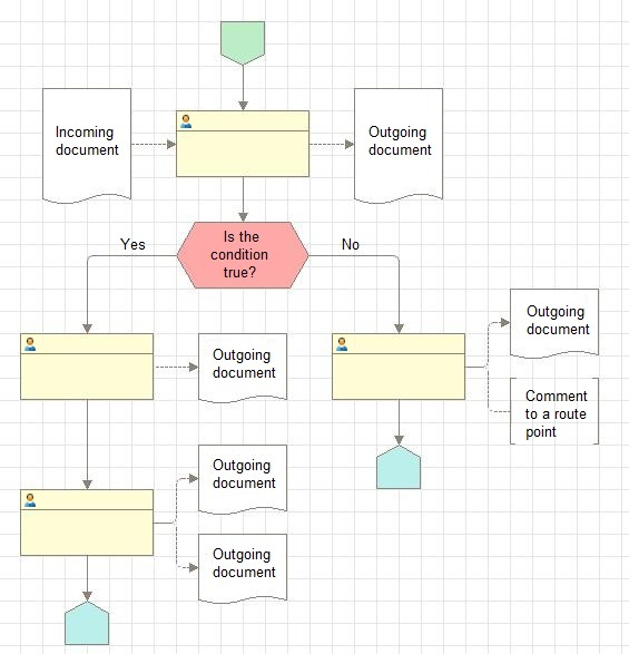
Business process layout example:
1. General recommendations
1.1 The recommended business process direction is top-to-bottom. Other directions are allowed if they provide a better description of the business process.
1.2 Use the standard grid, which consists of lines with a 20-pixel step.
1.3 Do not use bold or colored fonts.
1.4 Minimize the number of connector line bends. Use no more than a single bend per line whenever possible (this might require adjusting the sizes and positions of the route points).
1.5 When placing decorations and route points, leave 1-square margins at the left and at the top.
1.6 Make the route point width equal to an even number of squares. This is required to reduce the number of connector line bends. The route point and decoration proportions must be close to matchbox proportions (for example, 3x6 squares). Avoid long and narrow route rectangles because they make route maps harder to read.
1.7 Use the "center" text alignment in route points and decorations, except for comments where the "left" alignment is preferable.
1.8 We recommend that in the print layout the page breaks do not cross decorations and route points (on the Graphical schema menu, click Page view mode).
2. Recommendations for specific graphical schema items
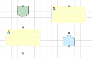
2.1 The Start and End points are 2x2 squares and have no names. The number of start and end points is not limited, it is defined by the business process logic. The recommended gap between a start or end point and another business process point is 2 squares:
2.2 The size of the Activity, Processing, and Subordinate business process points is defined by the text they contain. The text must be a short directive describing the activity, such as "Issue invoice" (not "Issuing invoice"). To the left of such points, place decorations that describe source (incoming) data required to perform the activity. To the right of such points, place decorations that describe resulting (outgoing) data that is generated by the activity.
2.3 Place shapes of incoming documents that are required by route point activities to the left of route points with a 2-square gap and connect them with dotted lines with arrows. Place shapes of outgoing documents that describe the route point activity results to the right of route points with a 2-square gap and connect them with dotted lines with arrows. Use the Document shape for documents.
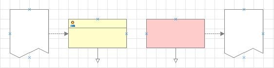
The proportions of the document decoration should be close to A4 proportions whenever possible (for example, 4x5 squares or 3x4 squares).
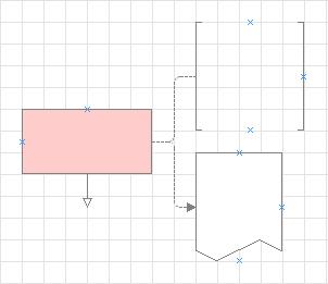
2.4 Place comments related to incoming documents to the left of route points with a 2-square gap. Place comments related to outgoing documents to the right of route points with a 2-square gap. Use the Vertical brackets or Horizontal brackets shape and connect it with the left or right border of the route point with a dotted line that does not have an arrow:
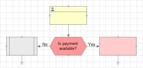
2.5 Condition points include a short question ending with a question mark. The wording should presume only Yes and No answers (for example, Is invoice available?, Is shipping allowed?, OK?). Make condition points as compact as possible but ensure that the scheme remains clear. This recommendation is based on the fact that condition points are transition points, they are less important than activity points. Condition connector lines, both incoming and outgoing, must be at least 2 squares long to ensure that the Yes and No words fit: